design considerations for borehole thermal energy storage
TRANSCRIPT

Review ArticleDesign Considerations for Borehole Thermal Energy Storage(BTES): A Review with Emphasis on Convective Heat Transfer
Helge Skarphagen,1 David Banks ,2,3 Bjørn S. Frengstad ,4 and Harald Gether1
1Gether AS, Bakkeveien 12, N-3292 Stavern, Norway2School of Engineering, James Watt Building (South), Glasgow University, Glasgow G12 8QQ, UK3Holymoor Consultancy Ltd., Chesterfield, Derbyshire S40 4BW, UK4Department of Geoscience and Petroleum, Norwegian University of Science and Technology (NTNU), N-7491 Trondheim, Norway
Correspondence should be addressed to David Banks; [email protected]
Received 27 September 2018; Accepted 13 January 2019; Published 22 April 2019
Guest Editor: Antonio Galgaro
Copyright © 2019 Helge Skarphagen et al. This is an open access article distributed under the Creative Commons AttributionLicense, which permits unrestricted use, distribution, and reproduction in any medium, provided the original work isproperly cited.
Borehole thermal energy storage (BTES) exploits the high volumetric heat capacity of rock-forming minerals and pore water tostore large quantities of heat (or cold) on a seasonal basis in the geological environment. The BTES is a volume of rock orsediment accessed via an array of borehole heat exchangers (BHE). Even well-designed BTES arrays will lose a significantquantity of heat to the adjacent and subjacent rocks/sediments and to the surface; both theoretical calculations and empiricalobservations suggest that seasonal thermal recovery factors in excess of 50% are difficult to obtain. Storage efficiency may bedramatically reduced in cases where (i) natural groundwater advection through the BTES removes stored heat, (ii) extensive freeconvection cells (thermosiphons) are allowed to form, and (iii) poor BTES design results in a high surface area/volume ratio ofthe array shape, allowing high conductive heat losses. The most efficient array shape will typically be a cylinder with similardimensions of diameter and depth, preferably with an insulated top surface. Despite the potential for moderate thermalrecovery, the sheer volume of thermal storage that the natural geological environment offers can still make BTES a veryattractive strategy for seasonal thermal energy storage within a “smart” district heat network, especially when coupled with moreefficient surficial engineered dynamic thermal energy stores (DTES).
1. Introduction and Terminology
The term “thermogeology” [1, 2] has been applied to the sci-ence of the occurrence, movement, and exploitation of heatin the earth’s subsurface. The ground can be used as a sinkor source of heat to provide heating, cooling, or dehumidifi-cation to residential and commercial spaces or to industrialor horticultural processes—a technological practice knownas ground source heating and cooling (GSHC). This is often,but not always, achieved by the use of ground source heatpumps (GSHP).
Most rocks and saturated sediments have rather highvolumetric heat capacities—typically around 2MJm-3 K-1.That of water is even higher—c. 4.19MJm-3 K-1. Because ofthese high values, the ground, and the groundwater it con-tains, can be used as thermal store or “accumulator.” Because
the ground beneath a development site has a huge volumeand thermal capacity, and because accessing it requirescapital-intensive drilling and geoengineering, undergroundthermal energy storage (UTES) is typically used for thelarge-scale seasonal storage of heat that is difficult to achieveusing conventional surface technologies. UTES can be subdi-vided into two categories:
(1) Borehole thermal energy storage (BTES), where afield of borehole heat exchangers (BHE) exchangesheat with the surrounding rock or sediment mass,predominantly by processes of conduction. In typicalcases, the surplus heat stored during the summermonths is extracted for space heating usage in winter(and/or vice versa in the case of “coolth”). One of theearliest BTES pilot projects was the Luleåvärme
HindawiGeofluidsVolume 2019, Article ID 4961781, 26 pageshttps://doi.org/10.1155/2019/4961781

Project, in Luleå, Sweden, which operated from 1983to 1989. Here, surplus industrial heat from a steelplant, supplied at temperatures of 70-80°C, wasseasonally stored in a BTES array of 120 number65m deep boreholes (10 × 12 array) in graniticgneisses, spaced at c. 4m and with an array volumeof c. 115 000m3 [3–7]. The annual recharge of heatwas some 2.3GWh, with around 1GWh recoveredannually. The temperature within the BTES rockmass was in excess of 50°C, reaching as high as 65°C
(2) Aquifer thermal energy storage (ATES), whichtypically involves paired doublets of extraction andreinjection wells, and where warm or cold water isintroduced (via the reinjection wells) under excesshead [8–10]. Heat is thus largely manipulated withinthe aquifer volume by means of “forced (head driven)convection” or “advection.” Early trials of high-temperature storage of hot (80-90°C) water tookplace in an interbedded sand/clay aquifer sequenceat Mobile, Alabama, USA [11, 12]. A well-publicised,recent, lower-temperature example of ATES is atArlanda Airport, Sweden [13, 14].
This paper will focus predominantly on seasonal storageof heat via BTES. Such heat storage is especially attractivein strongly seasonal climates, and the paper will particularlyfocus on BTES in the fractured crystalline rock terrain prev-alent in Fennoscandia and Canada, although the generalprinciples also apply to porous medium aquifers and moretemperate climates. Comprehensive analyses and reports onthe theory and practice of UTES and BTES were producedin the 1980s and 1990s, which are still regarded as key litera-ture on the topic today, notably
(i) Gerardus van Meurs’ thesis on seasonal heat storagein conventional porous sediments [15]
(ii) Claesson et al.’s report on analytical solutions toground source heat problems, including seasonalstorage in BTES [16]
(iii) Göran Hellström’s analysis of the thermophysics ofborehole heat exchangers and their application tosubsurface heat storage [17]
(iv) Bo Nordell’s thesis on the design and optimisation ofBTES systems [3]
Documented examples of established BTES include
(i) the summer harvesting of solar heat (by solar ther-mal rooftop collectors) at a housing development inDrake Landing, Canada [18–20]. The BTES arraycomprises a cylindrical array of 144 boreholes to35m depth (volume 34,000m3).
(ii) A similar district heating system, relying on sum-mer harvesting of solar heat and storage in aBTES array comprising 100 boreholes to 65mdepth, spaced at 3m, (volume 65,000m3) in
crystalline bedrock at Anneberg, near Stockholm,Sweden [21]
(iii) Another district heating system at Neckarsulm,Germany, storing summer solar thermal energyat temperatures of up to 80°C in a rock mass,via a BTES system of volume 63,360m3 compris-ing (as of 2006) 528 borehole heat exchangers todepth 30m [22]. The borehole spacing is as littleas 2m [23]
(iv) Richard Stockton College, New Jersey, USA, wherea 1.2 million m3 BTES system services loads of upto 5MW and reportedly comprised an array of400 boreholes of 135m depth [24]
(v) The Kemicentrum, Lund, Sweden [25], which uti-lises an array of 153 boreholes to 230m deep tosupport a heating load of 6790MWh (peak load c.5MW) and a cooling load of 5400MWh (peak loadc. 3MW).
(vi) Avantor, Nydalen Industry Park, Oslo, Norway[26, 27], utilises a BTES system of 180 boreholesto 200m depth in crystalline bedrock, spaced at7m, to deliver c. 6MW heating effect and 9.5MWcooling effect
(vii) An archive building in Shanghai, which operates aGSHC system of up to 1MW capacity, with astrong element of BTES, utilising 280 boreholes of80m depth [28].
(viii) The high-temperature BTES at Emmaboda, Sweden[7, 29, 30], which has, since its initiation in 2010,stored around 10GWh of industrial waste heat(with source temperatures ranging from 58 to90°C, but supplied to the BTES at up to 55°C)in a 10 × 14 array of 140 boreholes, spaced at c.4m, drilled to 150m deep in bedrock predomi-nantly comprising granodiorite. The BTES stor-age volume was some 323,000m3, while theground temperature within the BTES array hadreached 40-45°C by 2015. The BTES is dividedinto 7 quasi-concentric sections that can be indi-vidually operated
Further reviews of the state of the art of BTES have beenextensively published by [31–43].
A borehole heat exchanger (BHE) is typically based on aborehole drilled at between 100 and 150mm diameter.Depths can be anything up to 350m: 35 to 150m is typicalfor continental Europe, but depths in excess of 200m arerather common in the crystalline rock terrain of Fennoscan-dia and the Faroes. The borehole accommodates some formof heat exchange pipe. This often takes the form of a U-shaped tube (i.e., upflow and downflow shanks). Alterna-tively, coaxial pipes or double-U pipes can be installed. Aheat transfer fluid is circulated (by pumping) around theborehole heat exchanger. The heat transfer fluid is oftenbased on a solution of antifreeze (ethanol is common in
2 Geofluids

Fennoscandia; ethylene or propylene glycol are commoner inthe UK), together with additives, such as biocides and corro-sion inhibitors. In high-temperature BTES, where the tem-perature of the fluid never approaches 0°C, then simplewater (possibly with additives) can be utilised. If the heattransfer fluid is warmer than the surrounding rocks, heat isrejected to the geological environment; if the heat transferfluid is cooler, then heat will be extracted. The heat transferfluid circulates to a heat exchanger or heat pump at the sur-face, by means of which space cooling, space heating, orindustrial/agricultural cooling are performed.
A BHE U-tube is commonly constructed of high-density polyethylene (HDPE) or cross-linked polyethylene(PEX) and is of 40mm (or sometimes 32mm) outsidediameter (OD). For higher-temperature BTES applications,the choice of material can be important as some polyeth-ylene types lose strength as temperature increases. Inhigh-temperature BTES systems, PEX, PE-RT (polyethyl-ene of raised temperature resistance) materials may bepreferred [38] and steel pipes may also become attractive.In high-temperature BTES systems, the thermal expansionof the ground in the BTES may become significant andground heave will need to be considered in any opera-tional risk assessment [2].
In Fennoscandian “hard” crystalline rocks (e.g.,gneisses, granites, schists), the BHE borehole is typicallyunlined (although a limited length of surface casing is typ-ically installed for stability). In such low-permeabilityrocks, in a wet climate, the water table is often close tothe surface and the boreholes are naturally groundwater-filled. It is this groundwater that provides the thermal con-tact between the heat exchange pipe and the rocks in theborehole walls.
In low-permeability crystalline Fennoscandian rock ter-rains, an “open coaxial” arrangement is sometimes used,employing a single pipe down the centre of the borehole,and using the surrounding borehole space as the outer coax-ial conduit: in this case, the heat exchange fluid is in directcontact with the borehole wall, leading to very efficient heatexchange [29].
In other geological environments (e.g., where the rocksare not fully lithified and self-supporting) or where thewater table is low, then the borehole can be backfilled witha low-permeability thermally enhanced grout, which pro-vides a thermally conductive contact between the heatexchange pipe and the geological environment. The boreholestructure itself thus possesses a “thermal resistance” (Rb) toheat flow.
2. Defining Thermal Efficiency: Ambient andHigh-Temperature BTES
“Heat” is a mathematical concept (unlike water, whose mol-ecules can be isotopically labelled, or which can be markedwith a chemical tracer), and the recovery of “particles” of heatcannot be empirically measured. We must thus be very care-ful when defining exactly what we mean by thermal storageor recovery efficiency.
Where a high-temperature source of waste heat exists,which is producing heat even at times of low demand(waste incinerator, combined heat and power (CHP) plant,and metallurgical industry), it is possible to store this wasteheat underground via a BTES array. During the initial yearsof operation, the BTES store (and the rock it encloses) is“charged up” with heat to the operating temperature(Figure 1), a process which often involves recharging signif-icantly more heat to the ground than is extracted. Duringthis phase, the temperature field around the BTES evolves;the ground surrounding the BTES warms up, and the tem-perature contrast between the BTES and the surroundingground decreases. At some stage, typically after 3-6 years,some kind of quasi-steady state will be achieved, wherethe operating temperature is reached and the annual heatloss to the surface and surrounding rocks becomes stable;this marks the start of the operational (steady-state phase).In fact, however, it will typically take many decades for atrue steady state to be achieved in the far temperature field.During an annual cycle (assuming it is a seasonal heatstore), a quantity of heat is recharged to the BTES, and aquantity of heat is extracted (normally, during winter). Ifthe system has entered a quasi-steady state and the long-term average temperature of the BTES is stable (it will, ofcourse, vary over an annual cycle), then the differencebetween the annual recharge and annual extraction can betaken to be the heat loss to the surrounding ground orthe surface. This heat loss will intuitively be
(i) proportional to the temperature difference betweenthe edge of the BTES array and the ambient groundtemperature
(ii) roughly proportional to the thermal conductivity ofthe ground
(iii) related to the geometry of the BTES array (e.g., thesurface area to volume ratio) and to any insulationapplied to the BTES
In such a case, the thermal recovery factor ηE is relativelyeasy to define: it is the ratio of the heat recovered to the heatrecharged over an annual cycle (or longer period).
However, there is another type of BTES, operating at lessextreme—approximately ambient—temperatures. Such ascheme is usually used at a business or building that has pre-dominantly cooling (heat rejection needs) in summer, bal-anced with a similar heating demand in winter; e.g., manyoffice buildings, hospitals, and greenhouse complexes. Insuch schemes, a heat pump will draw heat from the buildingin summer via a chiller circuit and reinject it, via the heatpump condenser, to the ground, at maybe 25°C. In winter,the BTES will be coupled to the heat pump’s evaporatorand a chilled heat transfer fluid (maybe a few degrees above0°C) will extract heat from the ground. Thus, the averagetemperature of the heat store will be around the ambientground temperature, extreme temperatures are avoided,and the heat pump operates very efficiently. The ground isthus prechilled for the summer cooling season and preheated(by rejected summer waste heat) for the winter heating
3Geofluids

season. In this case, the simple thermal recovery factor ηE isdifficult to apply as heat is not, in a sense, “lost.” In thesecases, it is perhaps more meaningful to compare the ambientBTES with the performance of a similar scheme where noseasonal storage is practiced, but where heat is solelyextracted from the ground in winter, but not replenished insummer. This paper thus defines
(i) the thermal recovery advantage as the additionalamount of heat extracted from a BTES, relative tothe amount that can be extracted in a base case where“recharge” of heat is not practised
Finally, in this paper we will also consider the rise in tem-perature of a BTES if heat is simply charged into the BTESyear on year, with no extraction.
Thermal accumulation J = Temperature increase K× BTES volume m3 × cv,
1
where cv is the volumetric heat capacity of the rockJm−3K−1 .
The thermal accumulation is the amount of heat that hasbeen retained within the BTES during the period in question.As the temperature of the BTES increases, the heat loss to thesurrounding environment will also increase; the rate of heataccumulation will decrease and the rate of temperature risewill decline. We will discuss a rather crude parameter:
(i) The thermal accumulation efficiency, defined as theestimated year on year accumulation of heat in aBTES array, calculated from the slope of the tempera-ture evolution under heat injection only conditions,divided by the total amount recharged
We will begin our consideration of BTES by examiningborehole heat exchangers and ambient BTES.
3. Heat Extraction and Storage via BoreholeHeat Exchangers (BHE)
The temperature field around a borehole heat exchanger canbe simulated as a line source (or sink) of heat [44, 45]. In theshort-medium term, this is adequately represented by the“line source” heat equation (equation (2)), apparently firstdeduced by Whitehead in 1927 [46] and later utilised in thecontext of groundwater abstraction by Clarence Lubin andCharles Theis [47]:
θ = θ0 +q
4πλEi u , 2
where
(i) θ is the average temperature at a given radial dis-tance (r) from the borehole axis at any time (t) fol-lowing commencement of heat rejection orextraction (°C or K)
(ii) θ0 is the average temperature of the rock mass alongthe length of the borehole, prior to commencementof heat rejection or extraction (°C or K)
(iii) q is the rate of heat rejection (positive) or extraction(negative) in watts per metre of borehole (Wm-1)
(iv) λ is the thermal conductivity of the rock (Wm-1 K-1)
(v) Ei is the exponential integral function
(vi) u = r2cv/4λt = r2/4αt (dimensionless)
(vii) α is the thermal diffusivity of the rock = λ/cv (m2 s-1)
The average temperature of the heat transfer fluid(i.e., the average of the flow and return temperaturesto/from the BHE = θb) is given by simply calculating thetemperature at the borehole wall (radius rb) and adding
Operating temperatureLong-term steady state
Annual cycle
Tem
pera
ture
Ambient BTES
High-temp. BTESR E
Year 1
10°C
45°C
55°C
Midwinter
Year 2 Year 3 Year 4 Year 5 Year 6 Year 7 Year 8
Ambient rock temperatureInitial transient “charging” phase
Figure 1: Schematic diagram of temperature evolution in a high-temperature BTES system, operating at around 45-55°C, and in an ambientBTES system serving balanced heating and cooling demands. Ambient rock temperature = 10°C. Temperatures are only indicative and willdepend on exactly where within the BTES they are measured. R = recharge of heat during summer and autumn; E = extraction of heat inwinter and spring.
4 Geofluids

a constant term to account for the borehole thermalresistance (Rb):
θb = θ0 + qRb +q
4πλEi ub , 3
where
(i) θb is the average temperature of the heat transferfluid at any time (t) following commencement ofheat rejection or extraction (°C or K)
(ii) Rb is the borehole thermal resistance (kmW-1)
(iii) ub = r2bcv/4λt = r2b/4αt (dimensionless)
(iv) rb is the radius of the borehole into which the BHE isinstalled (m)
Let us imagine a single borehole heat exchanger, installedin a borehole 100m deep and 120mm diameter, with a bore-hole thermal resistance of 0.08 kmW-1 (quite typical figuresfor a well-constructed, thermally efficient BHE). Let us fur-ther assume that the rock has a thermal conductivity of2.48Wm-1 K-1 and a volumetric heat capacity of 2.4MJm-3
K-1 and that the average initial rock temperature along theborehole length is 11°C (reasonably typical for an acidic igne-ous rock or sandstone in temperate Europe). Let us furtherassume a thermal load scenario (Scenario 1) as follows:
(i) For four months in summer (May-August),9000 kWh (32400MJ) of surplus heat is rejected tothe BHE. This works out at an average rate of3.08 kW, or q = 30 8Wm−1. Days 0 to 122
(ii) For the next two months (Sept.-Oct.), the boreholedoes not extract or reject heat. Days 122 to 183
(iii) For four months of winter (November-February),9000 kWh (32400MJ) of heat is extracted from theborehole (presumably by means of a heat pump,given the low temperatures involved). This worksout at an average rate of -3.08 kW, or q = −30 8Wm−1. Days 183 to 304
(iv) Thereafter, the borehole remains inoperative
This will be compared in the following discussion with asecond scenario (scenario 2—no heat recharge), where thereis no initial heat rejection phase, but merely
(i) 9000 kWh (32400 MJ) of heat extraction at a constantrate fromNovember to February. This works out at anaverage rate of -3.08 kW, or q = −30 8Wm−1. Days183 to 304
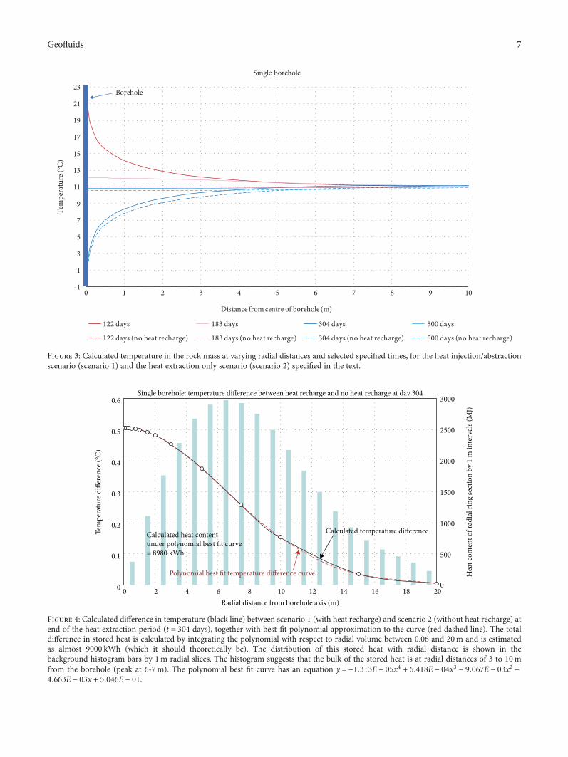
Application of equations (2) and (3) in a spreadsheetenvironment allows us to calculate the temperature of theheat transfer fluid and the temperature at the borehole walland at various radial distances into the rock mass from theborehole axis (Figure 2). Figure 3 plots this data against radialdistance for various times, and it can be seen that
temperature decays approximately with the logarithm ofradial distance from the borehole.
It will also be noted that the difference in average heattransfer fluid temperature between scenario 1 (with the initialinjection of 9000 kWh of heat in months 1-4) and scenario 2(no heat recharge; only heat extraction in months 6-10) istypically only a little over 0.5°C. In other words, the benefitof recharging 9000 kWh of heat to a single borehole duringsummer months is typically a slightly elevated heat transferfluid temperature during the subsequent heat extractionphase, to the tune of some 0.5 to 1°C. This would result in aslightly improved heat pump performance, and one can thusargue that the recharged heat has been recovered, but not inan especially noticeable or economically advantageous man-ner. In Figure 4, the temperature difference between the sce-narios with and without heat recharge is shown as a functionof distance at the end of the heat extraction season (day 304).It can be seen that the temperature difference becomes verysmall (<0.1°C) beyond 12m, and in the immediate vicinityof the borehole, it is around 0.5°C. One can calculate the“stored” heat that this temperature difference (Δθ) representsby multiplying the volume of successive radial sections by thevolumetric heat capacity and the temperature difference(2πrH × δr × cV × Δθ). This calculation verifies that almostall the 9000 kWh recharged heat is stored in the rock aroundthe borehole within the zone r = 0 06 to 20m. The bulk of theheat is, however, stored in the zone 3-10m, with the maxi-mum quantity of stored heat at around r = 6-7m (Figure 4).
4. Thermal RecoveryAdvantage—Single Borehole
To attempt to quantify the utility of the heat recharge in sce-nario 1, one can compare the operational heat transfer fluidtemperature during scenario 2 without heat injection(-0.18°C at day 304) and then increase the heat extractionrate in scenario 1 (with heat recharge) until a similar heattransfer fluid temperature is achieved—i.e., our previouslydefined thermal recovery advantage (see above). It is foundthat a heat injection (months 1-4) of 9000 kWh, followedby a heat extraction (months 6-10) of 9500 kWh, gives a sim-ilar heat transfer fluid temperature profile to that achieved bythe extraction of 9000 kWh heat (no heat recharge). Thus,one can say that the effect of recharging 9000 kWh of heatto a single BHE in summer is to allow the equivalent of anadditional extraction of 500 kWh of heat during winter: athermal recovery advantage of only 5.6%.
One could reasonably argue that this is unduly pessimis-tic. In the scenario where balanced heat recharge and extrac-tion are practised year on year, there is no long-termdownwards “drift” in temperatures. In the scenario with win-ter heat extraction only, temperatures will progressively(though slowly) decline year upon year. In fact, one can cal-culate that at the end of the 15th heat extraction season, theaverage heat transfer fluid temperature would be -1.44°C. Inthe scenario with heat recharge of 9000 kWh during summer,one could extract 10650 kWh during winter to yield a similar
5Geofluids

fluid temperature—a thermal recovery advantage of1650 kWh (18.3%).
5. Larger BHE Arrays for Thermal Storage
However, due to the relatively modest improvements inoperating temperature, it is not normally considered efficientto use single BHEs or small arrays of BHE to store heat(although it may arguably still be worthwhile if the surplusinjected heat has little or no alternative value and can berecharged to the ground for little additional cost). This con-clusion concurs with that of Kjellsson et al. [48], who alsofound that summer solar heat recharged to a single borehole“leaks” away rapidly—small thermal advantages mightaccrue, but these might easily be counterbalanced by theadditional costs of circulation pumps, etc., involved in thesummer recharge operation. To store heat efficiently, it iscommon to use large arrays of boreholes drilled in square,hexagonal, or cylindrical array shapes (Figure 5), at distancesof a few metres (3–7m are typical) such that, as demon-strated above, the heat storage fields of each borehole overlapand are intercepted efficiently by adjacent boreholes. It is,
moreover, important that the overall array volume is as“closed” as possible, meaning that the array’s surface-area-to-volume ratio is minimised. Thus, a long line of 36 bore-holes will not be efficient at storing heat, as each borehole willbe exposed on two sides to unexploited rock, through whichheat can conduct away. A square array of 6 × 6 boreholes(dimension 30m × 30m, if boreholes spaced at 6m) will befar more efficient at storing heat. The perimeter of the squarearray, through which heat can be lost to unexploited rock, isonly 120m, compared with 420m for the linear array (spacedat 6m).
Figure 6 compares the performance of a 6 × 6 array of36 × 100m deep boreholes, spaced at 6m, with heat extrac-tion and rejection loads comparable to those in Figures 1–3above (i.e., 36 × 9000 kWh = 324MWh), evenly distributedover a 4-month heat rejection season (“summer”) and a 4-month heat extraction season (“winter”) separated by a 2-month nonoperational period. The borehole constructionsare also identical to those described for Figures 2 and 3(above), and the scenario is simulated in the software EarthEnergy Designer (EED) version 3 [49].
Figure 6(a) plots four scenarios:
–1
1
3
5
7
9
11
13
15
17
19
21
23
0 100 200 300 400 500 600 700
Tem
pera
ture
(°C)
Days
Single borehole
Heat transfer fluid Borehole wall (r = 60 mm)Heat transfer fluid (no heat recharge) Borehole wall (no heat recharge)1 m 3 m1 m (no heat recharge) 3 m (no heat recharge)Initial average rock temperature
Initial temperature = 11°C
Heat transfer fluid
Heat transfer fluid
Borehole wall
Borehole wall
r = 1 m
r = 1 m
r = 3 m
r = 3 m
Figure 2: Calculated average heat transfer fluid temperature and temperature at the borehole wall (r = 0 06m) and in the rock mass at radialdistances of 1m and 3m from the borehole axis, for heat injection/abstraction scenario (scenario 1) specified in text.
6 Geofluids
-1
1
3
5
7
9
11
13
15
17
19
21
23
0 1 2 3 4 5 6 7 8 9 10
Tem
pera
ture
(°C)
Distance from centre of borehole (m)
Single borehole
122 days 183 days 304 days 500 days
122 days (no heat recharge) 183 days (no heat recharge) 304 days (no heat recharge) 500 days (no heat recharge)
Borehole
Figure 3: Calculated temperature in the rock mass at varying radial distances and selected specified times, for the heat injection/abstractionscenario (scenario 1) and the heat extraction only scenario (scenario 2) specified in the text.
Figure 4: Calculated difference in temperature (black line) between scenario 1 (with heat recharge) and scenario 2 (without heat recharge) atend of the heat extraction period (t = 304 days), together with best-fit polynomial approximation to the curve (red dashed line). The totaldifference in stored heat is calculated by integrating the polynomial with respect to radial volume between 0.06 and 20m and is estimatedas almost 9000 kWh (which it should theoretically be). The distribution of this stored heat with radial distance is shown in thebackground histogram bars by 1m radial slices. The histogram suggests that the bulk of the stored heat is at radial distances of 3 to 10mfrom the borehole (peak at 6-7m). The polynomial best fit curve has an equation y = −1 313E − 05x4 + 6 418E − 04x3 − 9 067E − 03x2 +4 663E − 03x + 5 046E − 01.
7Geofluids

(i) A balanced heat rejection/extraction scenario for the36 boreholes, with heat loads of 324MWh perannum. The maximum summer and minimumwinter average heat transfer fluid temperatures areplotted, and these are typically around +22°C andjust below 0°C, respectively (and hence fully compat-ible with Figure 2)
(ii) A “heat rejection only” scenario for the 36 boreholes,with a heat rejection of 324MWh per annum, spreadover 4 months. The temperatures climb rapidly yearon year, with a maximum summer heat transfer fluidtemperature of around +36°C in year 15 and+ 38.6°C in year 25
(iii) A “heat extraction only” scenario for the 36 bore-holes, with a heat out-take of 324MWh per annum,spread over 4 months. The temperatures droprapidly year on year, with a minimum winter heattransfer fluid temperature of around -14°C in year15 and -16.6°C in year 25. It should here be notedthat these temperatures are far lower than wouldbe experienced in real GSHC schemes—at such
temperatures, the ground and heat transfer fluidwould freeze, latent heat of freezing would bereleased, and geotechnical (frost heave, or U-tubecompression) issues might be experienced. As EEDdoes not consider latent heat of freezing, these sce-narios can only be considered “hypothetical” andrepresentative of sensible heat balance
(iv) The plot also shows the summer maximum and win-ter minimum temperatures for a single borehole in“rejection only” and “extraction only” modes
Although the single borehole curves do show a year-on-year trend (as noted above), the trend is very shallow com-pared with the 36-borehole array “rejection only” and“extraction only” curves, immediately demonstrating thatthe 36-borehole array is far more efficient at “accumulating”or storing heat and “coolth” than the single borehole. Indeed,while in the 36-borehole “extraction only” scenario, the fluidtemperature reaches just below -2°C in the first winter; in theheat “storage” scenario, one could extract 400 kWh (follow-ing the rejection of 324 kWh) to bring the temperature downto -2°C. This additional 76MWh represents a first-year
20 m
(a)
10 m
(b)
(c)
(d) (e)
Figure 5: Different array shapes for BTES thermal energy storage. (a) Two BHE spaced >20m apart will typically not thermally interfere witheach other; (b) if the spacing is <10m, however, thermal interference can become significant (depending on thermal energy loadings). (c) Alinear array of closely spaced BHE will not be especially efficient at storing heat, due to the large perimeter through which heat can be lost. (d)A more “closed” array shape, such as a square grid of BHE, will be more efficient at storing heat, although (e) larger hexagonal or cylindricalarrays will be even more efficient, due to the declining ratio of surface area to volume as array size increases.
8 Geofluids

0
20
40
60
80
100
120
–20
–15
–10
–5
0
5
10
15
20
25
30
35
40
Hea
t add
ed to
stor
age p
er y
ear (
heat
reje
ctio
n on
ly -
MW
h)
Aver
age h
eat t
rans
fer fl
uid
tem
pera
ture
(°C)
Comparison of heat storage: single borehole versus 36-borehole array
Summer (maximum)
Summer (maximum)
Winter (minimum)
Winter (minimum)
36 boreholes, heat extraction only
36 boreholes, heat rejection only
0 5 10 15 20 25
Year of operation
Range of operation of BTES storage (36 bores)with balanced heat extraction and rejection
Summer (heat rejection)
Winter (heat extraction)
36-borehole array - heat storage (max and min)Single borehole - heat rejection only (max)
Single borehole - heat extraction only (min)MWh heat added to storage (rejection only)
(a)
Aver
age h
eat t
rans
fer fl
uid
tem
pera
ture
(°C)
Summer (maximum)
Winter (minimum)
81 boreholes, heat extraction only
Summer (maximum)
Winter (minimum)81 boreholes, heat rejection only
0
20
40
60
80
100
120
–20
–15
–10
–5
0
5
10
15
20
25
30
35
40
0 5 10 15 20 25
Hea
t add
ed to
stor
age p
er y
ear (
heat
reje
ctio
n on
ly -
MW
h)
Year of operation
Comparison of heat storage: 81-borehole cubic array
81-borehole array - heat storage (max and min)MWh heat added to storage (rejection only)
Range of operation of BTES storage (81 bores)with balanced heat extraction and rejection
Summer (heat rejection)
Winter (heat extraction)
(b)
Figure 6: Average heat transfer fluid temperatures in a BHE array. The grey envelope in the middle of the diagram shows the range of heattransfer fluid temperature for a BTES where heat extraction and rejection are seasonally balanced (324MWh/season, each across a 4-monthextraction and rejection season). The envelope between the red dotted lines indicates the typical heat transfer fluid temperature range for aBTES where heat is being rejected year on year (324MWh/season; maximum temperature in summer, minimum in winter); the envelopebetween the blue dotted lines indicates the range of heat transfer fluid temperature for a BTES where heat is being extracted year on year(324MWh/season). In both diagrams, the green dotted line shows the estimated annual marginal heat accumulation in the BHE storage inthe case of heat rejection only (calculated from the gradient of the heat rejection temperature curve, a rock volumetric heat capacity of2.4MJ/m3/K, and a BTES volume of 90,000m3). (a) An array of 36 number, 100m deep boreholes on a 6 × 6 square grid at 6m spacing;(b) an array of 81 number, 44.4m deep boreholes on a 9 × 9 square grid at 5.6m spacing. (a) also shows the temperature curve for acomparable single 100m deep borehole extracting or rejecting 9MWh heat per 4-month season (i.e., 324MWh/36). Initial ambientaverage ground temperature = 11°C.
9Geofluids

thermal recovery advantage of 23% (compare with 5.6% forthe single borehole).
6. Effect of Array Geometry
One could argue that the 6 × 6 array of 36 boreholes is still aninefficient shape in terms of heat storage, as the depth(100m) is still far greater than the lateral dimension (30m).The volume of the array is thus 90,000m3, and the surfacearea 13,800 m2, giving a surface area-to-volume ratio of0.153m-1. By designing the array as a more evenly dimen-sioned shape (lateral dimension approximately equal todepth), the surface area/volume ratio could be reduced to0.124m-1 for a cylinder of radius 24m and depth 49m or to0.134m-1 for a cubic configuration of depth and width c.45m (all have volume 90,000m2). Figure 7 plots the surfacearea-to-volume ratio, versus volume for a variety of bulkBTES shapes. A spherical shape is effectively impossible toachieve in the context of a BTES array comprising linearboreholes. The next most efficient common array shape is acylindrical array, where the depth is equal to the diameter.In this context, it can be noted that the Canadian DrakeLanding scheme comprises a cylindrical array of 144 bore-holes, spaced at 2.25m and drilled to 37m deep. The arrayhas a diameter of around 35m, approximately equal to depth,thus minimising surface area-to-volume ratio [20].
To test the effect of array geometry, the Earth EnergyDesigner simulation (Figure 6(a)) has been rerun for thesame heat loads, but applied to an array comprising a cubicarray of 81 boreholes, 44.4m deep on a 9 × 9 grid, spaced at5.6m (44.8m array width), giving a total drilled length of3596m, an array volume of 89,100m3 (almost identical tothe array simulated in Figure 6(a)), and an array surface areaof 11,970m2. This gives a significantly reduced surface area-to-volume ratio of 0.134m-1. The results of the simulation areplotted in Figure 6(b) and are superficially rather similar toFigure 6(a). The main difference is
(i) that, in the early years, the temperature gradient ofthe “heat rejection only” curve is steeper thanFigure 6(a), representing heat accumulation rates of80-100MWh/a (thermal accumulation efficiency of25-30%).
(ii) In later years, however, the rate of temperature andheat accumulation flattens out (thermal accumula-tion efficiency of <10%) to a greater degree thanFigure 6(a)
The first observation is as one would expect: the lowersurface area-to-volume ratio of the cubic array leads to moreefficient accumulation of heat. The second observation sug-gests that not all forms of array surface area are equal andthat the ground-surface interface (which is much larger inFigure 5(b): 2007m2 for the 9 × 9 array, as opposed to900m2 for the 6 × 6 array) is particularly effective at losingheat. Indeed, in Earth Energy Designer [49], while the rockmass is simulated as an infinite conductive medium, theground surface is effectively simulated as a constant
temperature (Dirichlet) boundary condition. Thus, depend-ing on the time perspective of thermal energy storage, model-ling suggests that particular attention should be paid to theground surface above the BTES array and that, in some cases,it may be desirable to minimise the area of the surface foot-print through which heat can be lost, or to insulate the sur-face footprint. Some authors [33] explicitly recommendinsulating the ground surface above the BTES array and, inthis case, identify a cylindrical array, where the depth is equalto the radius, as the most thermally efficient solution (interms of surface area-to-volume ratio, provided that theupper thermal insulation is “ideal”). This solution is alsoshown in Figure 7 as “Cylinder (depth = radius) top surfaceinsulated.” Indeed, the BTES system at Neckarsulm in SWGermany [22, 33] closely approaches an idealised geometryand the top surface of the BTES is insulated with a 20 cmlayer of extruded polystyrene and then backfilled to a depthof 3-4m [23]. The top surface of the BTES at Emmaboda,Sweden, is insulated by 0.4m of foam glass [30].
7. Effect of Borehole Spacing
As a final experiment in the Earth Energy Designer [49]modelling environment, another BTES of 90,000m3 has beensimulated, but this time with 289 boreholes (17 × 17 grid) to44.4m spaced at 2.8m. The BTES thus has the same overalldimension as Figure 5(b), but the borehole spacing has beenhalved and the number of boreholes (and total drilledmetres) has been increased by a factor of 3.56. Applyingexactly the same heat extraction and rejection loads asFigures 6(a) and 6(b) (324MWh per 4-month heat extractionor rejection season) results in the temperature evolutioncurves shown in Figure 8. The average heat transfer per metreof borehole has thus dropped from 30.8Wm-1 to 8.6Wm-1.
It will be noted, in the case of heat rejection only, that thetemperature of the BTES increases (Figure 8) at almost thesame rate as in Figure 6(b): i.e., the dotted green line has analmost identical trajectory, with around 100MWh of heatbeing added per year in the early years and < 10MWh peryear being added after year 20. The main difference is that,because the heat loads are being distributed across largernumbers of boreholes, the heat transfer fluid temperaturesin each borehole are far less extreme than in Figure 6(b). Inthe case with balanced rejection and abstraction, the operat-ing temperatures are just over +5°C in the winter and around+16°C in the summer (compare with -0.5°C and +23°C,respectively, in the case of Figure 5(b)). This will result in avery significant difference in the efficiency of operation ofany heat pump and may even permit the use of free cooling(as opposed to compressor-powered cooling) in the summer.The importance of achieving a thermal balance between heatrejection and extraction is well recognised: actually achievingthis balance in real large buildings, whose needs are oftendominated by cooling, is considerably more difficult. Variousways have been considered [50] of utilising excess rejectedheat directed towards Haukeland Hospital’s GSHC system(165 boreholes on a 5 × 33 grid spaced at 6m) in Bergen. Inother words, decreasing the borehole spacing from, say, 6mto 3m, does not make any great difference to the total storage
10 Geofluids

0
0.05
Surfa
ce ar
ea to
vol
ume r
atio
(m–1
)
0.1
0.15
0.2
0.25
0.3
0.35
0 50000 100000 150000 200000 250000
Volume (m3)
Surface area to volume ratio of various geometric shapes
Sphere CubePerfect cylinder (depth = diameter) Cuboid (depth = 3 × width)Cylinder (depth = radius) top surface insulated
Figure 7: Surface area-to-volume ratio of various geometric shapes as a function of volume.
Figure 8: The maximum (summer) andminimum (winter) average heat transfer fluid temperatures in a BHE array, in cases where a balancedheat extraction and heat rejection (324MWh/season, each across a 4-month extraction and rejection season) is applied, compared with thesame system where heat rejection only (324MWh/season) and where heat extraction only (324MWh/season) are practised. The BTES is anarray of 289 number, 44.4m deep boreholes on a 17 × 17 square grid at 2.8m spacing (i.e., the same BTES volume as Figure 5(b), but with halfthe borehole spacing). The green dotted line shows the estimated annual marginal heat accumulation in the BHE storage in the case of heatrejection only (calculated from the gradient of the heat rejection temperature curve, a rock volumetric heat capacity of 2.4MJ/m3/K, and aBTES volume of 90,000m3). Initial ambient average ground temperature = 11°C.
11Geofluids

efficiency of the BTES (all other things, including overallBTES dimension) being equal, but it has a significant impacton how efficiently that thermal storage can be accessed.
Amongst the forest of BTES theory, it is important toremember practical considerations. One major factor, whendrilling closely spaced boreholes, is to remember that bore-holes are not always vertical. Indeed, the quick and cheapdrilling method (down the hole hammer drilling) favouredby many BHE practitioners can result in very substantialdeviations. At Emmaboda, Sweden [30], the deviation of 21(randomly selected) boreholes of the total of 140 boreholesin the granodiorite rock was measured. At 150m depth, thehorizontal “drift” of borehole trajectory varied from 4m to26m, with an average of 16m (i.e., over 1m horizontal driftfor every 10m drilled). Thus, if one drills on a tidy rectangu-lar grid at 4m spacing, one must realise that the true situationat depth may be very different, and there is always the risk ofdrilling through an adjacent borehole.
8. High-Temperature Heat Storage by BTES
As we have already noted, in many larger BTES schemes, heatis not stored around the ambient ground temperature, butrather at high temperatures characteristic of waste heat fromindustrial, combustion, or incineration processes. The gen-eral principles of borehole spacing and array geometry dis-cussed above apply to high-temperature BTES arrays.However, determining the efficiency of heat storage issomewhat simpler.
In such schemes, the first few years of BTES operation aretypically dedicated to “charging up” the BTES with surplusheat, with little or no extraction. As the temperature withinthe BTES increases, the rate of heat loss to the surroundingrocks also increases and eventually a steady-state heat loss(Qss) is approached where the bulk temperature of the BTESceases to increase sharply (this can be observed in the “heatrejection only” curves of Figures 6(a) and 6(b)). It is com-monly claimed in the literature [51] that the recovery effi-ciency of a BTES increases over the first year of operation(the transient phase) as the rock volume in and around theBTES increases towards an operational temperature. As therock around the BTES begins to warm up, relative conductiveheat losses from the BTES decrease. However, an “honest”account of storage efficiency should ideally recognise thequantities of heat that have had to be “dispersed” into thesurrounding rock mass to achieve this effect. For example,it is claimed that the “BTES efficiency” of the Canadian DrakeLanding BTES scheme increased from 9% to 40% over thefirst four years of operation [19].
At steady state, cyclical seasonal storage and extractioncan commence. The amount of heat charged to the BTESstore will typically exceed the amount of heat discharged bya quantity Qss over an annual cycle, thus ensuring that theaverage temperature of the BTES is maintained. In this case,the thermal recovery factor (ηe) is defined [17] as
ηe =Heat extracted over an annual cycleHeat recharged over an annual cycle
4
To achieve a high thermal recovery factor, the steady-state heat loss (which is a function of temperature, BTESgeometry, rock thermal conductivity, and insulation) shouldbe as low as possible, while the seasonal transfer should be ashigh as possible. Hellström [17] argues that heat transfer in aBTES can be analysed in terms of three components:
(i) An initial transient thermal build-up of the temper-ature field around the BTES
(ii) A steady-state heat loss (Qss) from the BTES
(iii) A superimposed periodic variation on an annual(or other) cycle. In idealised analysis, this may beapproximated as a sinusoidal function
Hellström [17] provides an idealised case study where theheat recharged to a BTES at any given time Q t is equal tothe sum ofQss and a sinusoidal storage recharge and recoverycomponent of amplitude Q1.
Q t =Qss +Q1eiφe2πt/tp , 5
where φ is a phase lag and tp is the period of the recharge-discharge cycle (typically annual, but potentially diurnal). Itis possible to demonstrate [17] that, to achieve a recovery fac-tor ηe > 30%, then Q1/Qss should exceed 3.7. To achievegreater >50% requires Q1/Qss to exceed 4.5. To put these fig-ures into perspective, analytical methods are also published[16, 17] for estimating Qss for a range of cylindrical and rect-angular BTES geometries (Table 1). Using these methods, wecan estimate that, for a 50°C heat store in a cylindrical top-insulated BTES of radius 60m and depth 60m, in a graniteof thermal conductivity 2.2Wm-1 K-1, one might expect asteady-state heat loss Qss of over 130 kW. This in turnimplies, that to get a thermal recovery factor of over 30%,we require a peak discharge rate of over 0.5MW of heat.
It is noteworthy that, even in the Neckarsulm BTES sys-tem, which is regarded [33] as approaching an ideal geome-try, thermal losses were relatively high, with only 20% ofthe charged solar heat (187 of 979MWh) being usefullyrecovered [22]. It may seem that commonly cited seasonalthermal storage efficiencies of 20-40% would not be espe-cially attractive. The new Swedish Emmaboda BTES, operat-ing at temperatures over 40°C, is believed to be on target toachieve a thermal recovery factor of over 60% [30], however.The attractiveness of such an approach depends, however, onthe value that is placed on surplus summer heat. In reality,this is often very low, to the extent that, in most major citiesin temperate and southern Europe, surplus heat is regardedas a waste product and considerable sums are spent on dis-posing of it.
Nordell [3] has also analysed the optimisation of BTESdesign, in terms of geometry, borehole spacing, shape, etc.,taking into account thermal physical factors, constructionfactors, and economic considerations. Amongst his findingsare the following:
12 Geofluids

(i) The greater the borehole thermal resistance, thegreater the optimum number of boreholes and thecloser their spacing
(ii) The greater the rock thermal conductivity, thegreater the borehole spacing and the fewer boreholesrequired
(iii) The bigger the store, the relatively smaller the heatloss. For an optimised BTES in a given set of Swedishconditions, the thermal recovery factor (theoreti-cally) exceeds 50% for a heat extraction capacity of1GWh/year
9. Free Convection within the BHEWater Column
It has already been noted that the BHE itself often comprisesone (or sometimes two) U-tubes of pipe installed down thelength of the borehole. The borehole itself is typicallybetween 100 and 150mm diameter. In incompletely lithifiedrocks or sediments, or where the water table is relatively deep,the borehole is commonly backfilled with a thermallyenhanced grout, often based either on a mixture of bentonite(to give low hydraulic conductivity) and fine silica sand (togive high thermal conductivity) or a thermally efficientcement mix. In situations where the rock is hard and lithifiedand where the water table is high (due to the rock’s low per-meability and/or to high rainfall), the borehole is left openand allowed to fill with natural groundwater. In this case,the groundwater provides the thermal contact between theBHE U-tube(s) and the walls of the borehole (Figure 9).
It has been shown that convection cells can start to occurin a fluid-filled vertical tube (borehole) when the temperaturegradient along the length of the borehole exceeds a certainthreshold [52–56]:
Critical gradient °Cm−1 =gβθcp
+Racritανgβr4
, 6
where g is the acceleration due to gravity (9.81m s-2), β is thefluid’s isobaric thermal expansion coefficient (K-1), θ is theabsolute temperature (K), cp is the fluid heat capacity at con-stant pressure (J kg-1 K-1), Racrit is the critical Rayleigh num-ber (which may be between 69 and 216, depending on thethermal conductivity of the borehole wall), α is the fluid’sthermal diffusivity (m2 s-1), ν is the kinematic viscosity(m2 s-1), and r is the bore radius (m). The Rayleigh numberis a dimensionless number for a fluid, indicating a tendencytowards buoyancy-driven or convective flow.
The implication of this equation is that only small tem-perature gradients are needed to initiate convection influid-filled boreholes, e.g., in boreholes as narrow as 50mmwith axial temperature gradients as low as 0.03°Cm-1 [52,57]—i.e., natural geothermal gradients.
Thus, the application of a heating or cooling load to apolyethylene U-tube within a water-filled borehole can beassumed to be sufficient to initiate free convection in thegroundwater column. This, in turn, enhances the heat trans-fer between the U-tube and the borehole wall. Water has arather low thermal conductivity of 0.6Wm-1 K-1. Thus, aborehole filled with static water would be expected to exhibita very high borehole thermal resistance (Rb—see equation
Table 1: Calculated steady-state heat losses from a cylindrical BTES array, with a temperature at the edge of the store of 50°C, an ambientundisturbed average rock temperature of 12°C, a rock thermal conductivity of 2.2Wm-1 K-1, and a rock volumetric heat capacity of2.2MJm-3 K-1 with expanded polystyrene insulation (thermal conductivity 0.04Wm-1 K-1) of thickness 0.5m extending over the top ofthe BTES and to a depth Di down the sides, using the mathematical technique of [17].
Radius Depth DiHeat losses Qss BTES heat capacity Heat capacity/QssInsulated top Insulated sides Uninsulated portion Total
m m m kW kW kW kW MWhK-1 MWhK-1 kW-1
20 60 6 3.8 1.1 38.8 43.8 46.1 1.1
30 60 6 8.6 1.7 53.2 63.5 103.7 1.6
45 60 6 19.3 2.6 74.3 96.2 233.3 2.4
60 60 6 34.4 3.4 95.5 133.3 414.7 3.1
80 60 6 61.1 4.6 123.7 189.4 737.2 3.9
20 60 12 3.8 2.3 34.1 40.2 46.1 1.1
30 60 12 8.6 3.4 46.2 58.2 103.7 1.8
45 60 12 19.3 5.2 63.8 88.3 233.3 2.6
60 60 12 34.4 6.9 81.5 122.8 414.7 3.4
80 60 12 61.1 9.2 105.1 175.4 737.2 4.2
20 100 6 3.8 1.1 48.9 53.9 76.8 1.4
30 100 6 8.6 1.7 65.0 75.3 172.8 2.3
45 100 6 19.3 2.6 89.1 111.0 388.8 3.5
60 100 6 34.4 3.4 112.9 150.8 691.2 4.6
80 100 6 61.1 4.6 144.6 210.3 1228.7 5.8
13Geofluids

(3)). In practice, this is not the case, and we can infer thatthermally driven convection is occurring within the watercolumn. To illustrate the importance of convection as amechanism for heat transfer within a BHE, SWECO carriedout thermal response tests (TRT) in several individualgroundwater-filled BHEs installed in the basalt rocks of theFaroe Islands [58]. The results are summarised in Table 2.
Very low borehole thermal resistances (Rb) of 0.066 to0.08 kmW-1 were obtained. The program Earth EnergyDesigner [49] can be used to simulate the theoretical Rb, fora 140mm borehole, installed with a 40mm single U-tube ata shank spacing of 70mm. A 25% ethanol heat transfer fluidhas been assumed, with a flow rate designed to give atransient-turbulent Reynolds number of c. 2500. If the bore-hole was assumed to be filled with static water (thermal con-ductivity 0.6WmK-1), resistances Rb of around 0.2 kmW-1
are calculated, over twice that actually observed. If the bore-hole is assumed to be filled with a thermally enhanced grout
with a conductivity of 1.7Wm-1 K-1, resistances Rb of around0.11 kmW-1 are calculated. Thus, free convection in agroundwater-filled borehole is demonstrated to be morethermally efficient than a borehole filled with a thermallyconductive grout of thermal conductivity 1.7WmK-1.
Moreover, the greater the temperature contrast betweenthe heat transfer fluid and the borehole walls, the greaterthe convective heat transfer effect. This is evidenced by adecrease in the Rb with increasing heat injection rates, fromthermal response tests in an 80m groundwater-filled BHEin crystalline, poorly fractured igneous bedrock at Göteborg,Sweden (110mm bore, single 40mm OD polyethylene U-tube [59]). With a heat injection rate of 28Wm-1, the bore-hole thermal resistance was estimated as 0.089 kmW-1. Atheat injection rates of 55, 70, and 142Wm-1, Rb fell to0.069, 0.068, and 0.051 kmW-1, respectively [60]. As the rockin this test borehole was poorly fractured, the thermallydriven convective effects are believed to be restricted to the
Convective heat transfer in groundwater-filled borehole
Conductive heat transfer in grout-filled boreholeConductive heat
transfer in unfractured rock
Conductive heat transfer in unfractured rock
�ermally conductivegrout (e.g., fine quartz sand/bentonite mix)
Coaxialcontraflow within
boreholeNaturalgroundwater
U-tube U-tube
Single central
pipe
Water(groundwater)
(a) (b) (c)
BoreholeBoreholeBorehole
Figure 9: (a) A groundwater-filled BHE in unfractured rock, where heat transfer from the two warm shanks (upflow and downflow) of aU-shaped heat exchange pipe to the borehole wall is facilitated by thermally driven convection; (b) a BHE backfilled with grout and whereconduction is the main heat transfer mechanism; a coaxial open borehole heat exchange arrangement.
Table 2: Results of thermal response tests carried out in groundwater-filled boreholes in the basalt rock sequences of the Faroe Islands, after[58]. ∗Artesian flow from borehole plugged during test.
Casingdepth (m)
Casing OD(mm)
Boreholedepth (m)
Borehole diameter(mm)
Rb from TRT(KmW-1)
Projected Rb during heatextraction (KmW-1)
Petur Egholm, Torshavn∗ 6 168 150 140 0.066 0.065
Jarðfeingi, Torshavn 9 168 200 140 0.08 0.10
Petur Hammer, Tvøroyri 6 168 200 140 0.07 0.095
14 Geofluids

borehole itself, rather than to a “thermosiphon” (see below)effect in the surrounding rock.
In order to minimise borehole thermal resistance, sev-eral BTES systems have omitted the U-tube altogether(Figure 9(c)). At Emmaboda [29], a BHE design has beendeveloped using a single pipe coaxially mounted in awater-filled borehole. The pipe is insulated by a concentriclayer of stagnant water. In operation, the heat transfer fluidis circulated down the pipe and up the annulus between thepipe and the borehole walls. To avoid fluid loss, the wallsmust be either cased or comprise essentially impermeablefracture-free hard rock. Testing at Emmaboda suggestedRb values as low as 0.02 kmW-1-.
10. Forced Convection through a BHE Array
For BHEs whose objective is solely to extract heat from theground (e.g., for space heating) or to reject heat to the ground(e.g., for space cooling or industrial cooling), flow of ground-water past the BHE is generally regarded as a positive factor.This is because the flow of groundwater carries with it a“cargo” of environmental heat that can replenish heat thathas been extracted from the ground or remove heat fromthe BHE and surrounding ground in the case of heat rejec-tion. This stabilises ground temperatures, preventing themfrom reaching extreme values that would result in poor heatpump performance. In the case where groundwater flow isdriven by regional topographically determined head gradi-ents, the concomitant heat transport with the flowing wateris termed forced convection or advection. The presence ofregional groundwater advection implies that a “plume” ofheat (or “coolth,” if heat extraction is being practiced)extends downgradient away from the BHE and increasesthe opportunity for downgradient thermal interference. Sig-nificant flow of groundwater in a geological stratum (or aqui-fer) requires two preconditions:
(i) That the aquifer has sufficient hydraulic conductivity(K) to permit water to percolate. Hydraulic conduc-tivity is simply the permeability of the rock mass withrespect to water
(ii) That there is a sufficient groundwater head gra-dient (i) to drive groundwater flow (i is dimen-sionless). The ultimate source of groundwaterhead gradient is usually different in topographic ele-vation (although other mechanisms, such as over-pressurisation of sedimentary basins, can result inhead gradients)
The groundwater flux (which is commonly also termedthe Darcy velocity or Darcy flux (vD)) in m3 per m2 cross sec-tion per day (i.e., m d-1) is given by Darcy’s law (assumingflow is laminar):
vD = −K i, 7
where K=hydraulic conductivity in m d-1. In the case of aBHE operating in a permeable rock or sediment mass with
flowing groundwater, the temperature of the heat transferfluid within, and of the rock around, the BHE will initiallychange (increase in the case of heat rejection, decrease inthe case of heat extraction) in accordance with the line sourceheat (equation (2) or (3)). Over time, however, the tempera-ture will then tend to stabilise and will eventually reach asteady-state temperature (θs). At any point (x, y) in a Carte-sian coordinate system, where groundwater flows in the +xdirection, the following equation can be derived [61, 62],based on equations for a moving line source of heat [63, 64]:
θs x, y − θ0 =q
2πλexp
vthex2α
K0vther2α
, 8
where the thermal velocity (vthe) is related to the Darcy veloc-ity (flux) (vD) [62]:
vthe =vDcVwat
cV9
(i) cV is the bulk volumetric heat capacity of the satu-rated aquifer and cVwat is the volumetric heat capac-ity of water (c. 4.19MJm-3 K-1)
(ii) r = radial distance from heat source = x2 + y2 m
(iii) K0 is the zero-order modified Bessel function of thesecond kind
It is found [62] that, for typical aquifer scenarios, theimpact of groundwater flow on BHE performance becomessignificant at Darcy fluxes of around 0.01md-1(previousevaluations [65] approximately concur with this finding),while at Darcy fluxes of around 1md-1, the groundwaterflux was sufficient to effectively maintain the BHE at closeto ambient ground temperatures. Van Meurs [15] alsoconcluded that heat losses from an underground thermalstore became significant at a Darcy flux in excess of0.05md-1 (5 × 10⁻⁷ m s−1 cited in [3]). It is also possibleto demonstrate [62] that the greater the Darcy flux, themore rapidly the thermal effects of the flux are seen (i.e., adeviation of heat transfer fluid temperature towards a steadystate): for a Darcy flux > 0 1md−1, some form of steady stateshould become apparent within a time frame of less than3 days.
On the other hand, for a BTES scheme, where theobjective is to build up a seasonal reserve of heat or“coolth,” groundwater flow is generally regarded as a nega-tive factor, as it will tend to “wash away” the accumulatedheat down the hydraulic gradient. As a general rule ofthumb, it seems reasonable to suppose that, if the thermaltransport velocity is large compared with the dimension ofthe BTES array, the effect of groundwater flow would besignificant. For example, let us consider a BTES array ofwidth 40m, within an aquifer of bulk volumetric heatcapacity (cV) 2.4MJm-3 K-1. The calculations given inTable 3 apply: it will be seen that, if the Darcy flux exceedsc. 1 cmd-1 (equivalent to a hydraulic conductivity of 1 ×10⁻⁵ m s−1—a fine sand or similar—coupled with a
15Geofluids
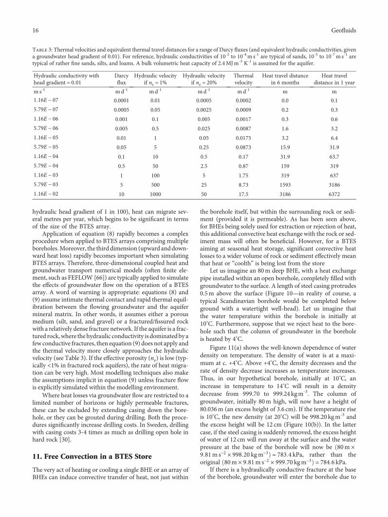
hydraulic head gradient of 1 in 100), heat can migrate sev-eral metres per year, which begins to be significant in termsof the size of the BTES array.
Application of equation (8) rapidly becomes a complexprocedure when applied to BTES arrays comprising multipleboreholes.Moreover, the thirddimension (upward anddown-ward heat loss) rapidly becomes important when simulatingBTES arrays. Therefore, three-dimensional coupled heat andgroundwater transport numerical models (often finite ele-ment, such as FEFLOW [66]) are typically applied to simulatethe effects of groundwater flow on the operation of a BTESarray. A word of warning is appropriate: equations (8) and(9) assume intimate thermal contact and rapid thermal equil-ibration between the flowing groundwater and the aquifermineral matrix. In other words, it assumes either a porousmedium (silt, sand, and gravel) or a fractured/fissured rockwith a relatively dense fracture network. If the aquifer is a frac-tured rock,where thehydraulic conductivity is dominated by afew conductive fractures, then equation (9) does not apply andthe thermal velocity more closely approaches the hydraulicvelocity (see Table 3). If the effective porosity (ne) is low (typ-ically <1% in fractured rock aquifers), the rate of heat migra-tion can be very high. Most modelling techniques also makethe assumptions implicit in equation (9) unless fracture flowis explicitly simulated within the modelling environment.
Where heat losses via groundwater flow are restricted to alimited number of horizons or highly permeable fractures,these can be excluded by extending casing down the bore-hole, or they can be grouted during drilling. Both the proce-dures significantly increase drilling costs. In Sweden, drillingwith casing costs 3-4 times as much as drilling open hole inhard rock [30].
11. Free Convection in a BTES Store
The very act of heating or cooling a single BHE or an array ofBHEs can induce convective transfer of heat, not just within
the borehole itself, but within the surrounding rock or sedi-ment (provided it is permeable). As has been seen above,for BHEs being solely used for extraction or rejection of heat,this additional convective heat exchange with the rock or sed-iment mass will often be beneficial. However, for a BTESaiming at seasonal heat storage, significant convective heatlosses to a wider volume of rock or sediment effectively meanthat heat or “coolth” is being lost from the store
Let us imagine an 80m deep BHE, with a heat exchangepipe installed within an open borehole, completely filled withgroundwater to the surface. A length of steel casing protrudes0.5m above the surface (Figure 10—in reality of course, atypical Scandinavian borehole would be completed belowground with a watertight well-head). Let us imagine thatthe water temperature within the borehole is initially at10°C. Furthermore, suppose that we reject heat to the bore-hole such that the column of groundwater in the boreholeis heated by 4°C.
Figure 11(a) shows the well-known dependence of waterdensity on temperature. The density of water is at a maxi-mum at c. +4°C. Above +4°C, the density decreases and therate of density decrease increases as temperature increases.Thus, in our hypothetical borehole, initially at 10°C, anincrease in temperature to 14°C will result in a densitydecrease from 999.70 to 999.24 kgm-3. The column ofgroundwater, initially 80m high, will now have a height of80.036m (an excess height of 3.6 cm). If the temperature riseis 10°C, the new density (at 20°C) will be 998.20 kgm-3 andthe excess height will be 12 cm (Figure 10(b)). In the lattercase, if the steel casing is suddenly removed, the excess heightof water of 12 cm will run away at the surface and the waterpressure at the base of the borehole will now be 80m ×9 81m s−2 × 998 20 kgm−3 = 783 4 kPa, rather than theoriginal 80m × 9 81m s−2 × 999 70 kgm−3 = 784 6 kPa.
If there is a hydraulically conductive fracture at the baseof the borehole, groundwater will enter the borehole due to
Table 3: Thermal velocities and equivalent thermal travel distances for a range of Darcy fluxes (and equivalent hydraulic conductivities, givena groundwater head gradient of 0.01). For reference, hydraulic conductivities of 10-2 to 10-4m s-1 are typical of sands, 10-5 to 10-7m s-1 aretypical of rather fine sands, silts, and loams. A bulk volumetric heat capacity of 2.4MJm-3 K-1 is assumed for the aquifer.
Hydraulic conductivity withhead gradient = 0 01
Darcyflux
Hydraulic velocityif ne = 1%
Hydraulic velocityif ne = 20%
Thermalvelocity
Heat travel distancein 6 months
Heat traveldistance in 1 year
m s-1 m d-1 md-1 md-1 md-1 m m
1 16E − 07 0.0001 0.01 0.0005 0.0002 0.0 0.1
5 79E − 07 0.0005 0.05 0.0025 0.0009 0.2 0.3
1 16E − 06 0.001 0.1 0.005 0.0017 0.3 0.6
5 79E − 06 0.005 0.5 0.025 0.0087 1.6 3.2
1 16E − 05 0.01 1 0.05 0.0175 3.2 6.4
5 79E − 05 0.05 5 0.25 0.0873 15.9 31.9
1 16E − 04 0.1 10 0.5 0.17 31.9 63.7
5 79E − 04 0.5 50 2.5 0.87 159 319
1 16E − 03 1 100 5 1.75 319 637
5 79E − 03 5 500 25 8.73 1593 3186
1 16E − 02 10 1000 50 17.5 3186 6372
16 Geofluids

the pressure difference of c. 1.12 kPa between the aquifer andthe borehole, and an equivalent amount of water will runaway at the surface. As the “new” water is heated by theBHE, a convection-driven thermal “pump” will develop, withgroundwater entering at the base of the borehole and runningaway at the surface (Figure 10(c)).
It should be possible to see that, if there is also a shallowhydraulically conductive fracture, 1m below ground level,there is no need for surface overflow to produce aconvection-driven system, whereas the initial pressure ofwater at the end of the fracture was equivalent to 1m ×9 81m s−2 × 999 70mgm−3 = 9807 kPa, the pressure afterheating by 20°C will be 1 12m × 9 81m s−2 × 998 20 kgm−3 = 10 967 kPa. The excess pressure (c. 1.2 kPa) will thusforce water into the fracture from the borehole, also remov-ing heat (as warm water) from the borehole environment.Because of the loss of water from the top of the borehole,new cool water will be drawn into the borehole by the oppo-site pressure differential at the base of the borehole and freeconvection will have been initiated. If the upper and lowerfractures are somehow hydraulically interconnected via abroader fracture network, then a convection cell will result(Figure 10(d)). If the fractures are not interconnected, thefree convection will reduce after some time as excess head
builds up in the upper fracture system, opposing the convec-tive energy.
By extrapolating this thought experiment still further, itshould be easy to see that in any given borehole, the com-ponents of a fracture network intersecting an open BHEabove the borehole’s (admittedly somewhat loosely defined)“hydraulic centre” will lose water upon heating, and thosebelow will gain fresh cool groundwater from the aquifer.By extending this further to an ever finer and denser net-work of fractures, it will be seen that such a BHE-drivenconvection cell could develop in an open borehole evenin an ideal porous medium aquifer. This effect is well-known and is termed the “thermosiphon effect” [69–73].
One would expect that the practice of grouting a BHEborehole, using a grout with high thermal conductivity (topromote efficient heat exchange) but low hydraulic conduc-tivity, would significantly reduce the likelihood of a thermo-siphon effect developing, because the open borehole formsthe main axis for thermally driven convective flow. Similarly,the practice of lining a BHE borehole with a casing extendingthroughout any permeable rock horizons (or to the base ofthe borehole) would also be effective at suppressing the ther-mosiphon effect. Theoretically, however, with a permeableenough rock matrix outside the borehole and with a high
Heat Heat Heat
Warm water runs away
Warm water exits the bore
Fracture
FractureFracture
Convection cell may be completed by hydraulic connectivity
some distance from the borehole
Cool water enters the bore
Cool water enters the bore
(a)
80 m
(b) (c) (d)
Figure 10: (a) A groundwater-filled, 80m deep BHE in unfractured rock, with a length of surface casing protruding above ground level;the groundwater level is at the surface. (b) If heat is rejected to the BHE, the groundwater heats up and expands, rising into the surfacecasing. (c) If the casing is removed, the excess water runs away at the surface; if a hydraulically conductive fracture exists at depth in theborehole, cool water will be drawn into the borehole due to the reduced heat and will subsequently expand, creating a thermally drivengroundwater flow up the borehole (a “thermosiphon” or thermal pump). (d) If a fracture exists at a higher level in the borehole, thewarm groundwater can flow away via that fracture, creating a convection cell within the surrounding rock or sediment mass, with theborehole as a central convecting axis.
17Geofluids

–0.8
–0.7
–0.6
–0.5
–0.4
–0.3
–0.2
–0.1
0
0.1
0.2
955
960
965
970
975
980
985
990
995
1000
1005
0 10 20 30 40 50 60 70
Den
sity
(kg/
m3 )
Slop
e (kg
/m3 /°C
)
Water temperature (°C)
Density of water
Density of water Rate of change of density with temperature
(a)
–0.600
–0.400
–0.200
0.000
0.200
0.400
0.600
0.800
0 5 10 15 20 25 30 35 40 45
Exce
ss w
ater
colu
mn
(m)
Original temperature (°C)
Excess water column generated by heating/cooling a column of groundwater
Heating mode Cooling mode
+20 °C
+10 °C
+4 °C
–20 °C
–10 °C
–4 °C
(b)
Figure 11: (a) The density of water and its dependence on temperature—based on data from [67, 68]; (b) from this data, it is possible tocalculate the excess height of water column caused by heating an 80m column of water by +4, +10, and +20°C, respectively. The blue linesshow the height decline caused by cooling the water column.
18 Geofluids

enough heat input, it might be possible to induce somedegree of convective circulation in the aquifer outside theBHE borehole. Finally, if the water table is deep, the thermo-siphon effect can be avoided by keeping the thermally activesection of the BHE entirely within the unsaturated zoneabove the water table.
It will be seen from Figure 11 that the rate of densitychange increases with increasing temperature, above 4°C.Thus, in the case of heat rejection:
(i) The greater the temperature difference between theheat transfer fluid and the ambient rock temperature,the greater the likelihood of thermally driven convec-tion or “thermosiphon” developing
(ii) The higher the initial temperature of the rock, thegreater the likelihood of thermally driven convectionor “thermosiphon” developing
Theoretically, of course, a thermosiphon effect could alsodevelop in cooling mode. However, in practice, because thedensity of water reaches a maximum at around +4°C, thedensity differences achievable by cooling the groundwaterin a borehole from an original temperature of 10°C (say)are rather low (see Figure 11(b)). It is only when the originalground temperature exceeds around 15°C that significantthermosiphon effects seem likely in heat extraction mode.For this reason, the storage of “coolth” in BHE arrays in per-meable fractured rocks is likely to suffer less from thermallydriven convective heat losses, than the storage of heat in sim-ilar arrays.
Testing of BHEs is typically undertaken by carrying out athermal response test (TRT) by constant injection of heat andobservation of temperature rise (on the assumption that, ifheat transfer is predominantly by conduction, the boreholewill behave similarly in heat extraction mode). It is found,however, that the thermosiphon effect can lead to significantoverestimation of rock thermal conductivity during TRTtests in groundwater-filled BHE in permeable fractured bed-rock. In fact, experiments have been carried out [60] on an80m deep, groundwater-filled borehole in fractured rock inGöteborg, Sweden. It was found that at a heat injection rateof 55Wm-1, the TRT yielded an estimate of apparent thermalconductivity of 3.19Wm-1 K-1 (believed to be reasonablyrepresentative of the “true” conductivity). Increasing the rateto 141Wm-1 resulted in a higher apparent thermal conduc-tivity of 3.57Wm-1 K-1, suggesting that 12% additional heatloss was due to thermally driven convective heat losses tothe surrounding aquifer.
While enhanced convective heat transfer between theBHE heat exchange pipe and the borehole wall will poten-tially occur in any water-filled borehole (see Free Convectionwithin the BHE Water Column), this will result in more effi-cient heat transfer in the borehole structure itself (i.e., lowerRb) and will not lead to greater heat losses from a BTESarray. Similarly, a “local” thermosiphon effect, which is notlaterally extensive, may have a positive impact in enhancingheat transfer between the borehole and the rocks immedi-ately surrounding it. However, a laterally extensive thermo-siphon effect will potentially lead to heat losses from a
BTES, but a prerequisite is that the surrounding rock con-tains hydraulically connected permeable horizons or frac-tures [73]. Extensive permeable fractures near the top (orthe base) of the water-filled section of the borehole will beparticularly disadvantageous as their presence implies thatthe thermosiphon will affect the entire length of the bore-hole. In large BTES systems, multiple water-filled boreholeswill themselves form vertical conduits interconnecting per-meable fractures, and the chances of forming a well-connected fracture system are enhanced.
Observation clearly suggests that, in many crystallinerock terrains, fracture permeability is typically highest inthe uppermost few tens of metres of a hard rock aquifer. Thisis partly due to the fact that fracture permeability tends todecrease with depth due to increasing loadings (increasingin situ stresses tending to close fracture apertures [74, 75]).More specifically, and especially in the case of northernEurope and Fennoscandia [76, 77], stress-relief fracturesand exfoliation joints often develop in the upper few tens ofmetres of a lithified rock mass, typically approximately paral-lel to the topography. These are usually ascribed to theremoval of an overburden, either by erosion or by meltingof a Pleistocene ice sheet and postglacial isostatic uplift.Moreover, it has been demonstrated [78] that the stressesbeneath a large ice sheet are sufficient to cause shallow shearfailure of crystalline rock. It has also been noted [76] thatgroundwater flow pathways may often develop as “hydro-fractures,” where natural fluid pressures exceed the normalcompressive stresses on a fracture plane (plus the tensilestrength of the rock if a new fracture is initiated). The waterpressures developed below and in front of a major glacialice sheet are sufficient to cause hydraulic fracturing of sedi-ments and the hydraulic opening of shallow fractures withincrystalline rock [78, 79]. Several authors report field evidenceof periglacial hydraulic opening of shallow fractures in Fen-noscandian crystalline rock [80–83]. For all these reasons,one might suppose that BTES systems in recently glaciatedhard-rock terrain might be particularly susceptible to heatloss by thermosiphon effects from open fractures and jointsin the shallow portion of a BHE.
12. Additional Strategies for Efficient ThermalEnergy Storage
Several additional strategies can be incorporated into a BTESsystem to improve efficiency and to increase flexibility ofoperation. The simulations of the BTES systems in the previ-ous sections have assumed that all the boreholes of the BTESare connected in parallel and “see” the same heat transferfluid temperatures and building loads. The system does not,of course, have to be designed in this way. In fact, it hasbecome accepted practice to design cylindrical BTES arrayswith two circular header pipes, one around the external cir-cumference of the array and one within the interior of thearray. BHEs are then connected in series along radials con-necting the two headers. It has been demonstrated above thatthe optimal design of circular BTES arrays can involve rela-tively short boreholes, with a depth similar to the lateralextent of the array. This, in turn, implies that connection of
19Geofluids

several boreholes in series can still result in relatively shorthydraulic path lengths without unduly high hydraulic headlosses. This arrangement means that the BTES array can bedivided into two (or more) concentric thermal zones(Figure 12). Reversing valves can be installed allowing theBTES heat transfer fluid to be directed from the outercircumferential header to the inner one, or vice versa. Forexample, in a BTES designed to store heat, when surplus heatis available (e.g., during hot summer days), the hot heattransfer fluid is directed towards the core of the BTES, whichis warmed to the highest temperature, and then radially out-wards, progressively warming the outer zones. When there isa heat demand, the cool heat transfer fluid is circulated fromthe outer circumferential header first and progressivelyinwards towards the inner header. Thus, the fluid is initially“prewarmed” by heat acquired from the BHEs in the outerzone of rock and finally is heated by the core of the BTESarray to its full temperature. In this way, the core of the arrayis always “charged” with heat first and discharged last; thecore is also always surrounded by the warm rock/sedimentof the outer zones and tends to retain its heat most efficiently.
In a BTES in a warm region, where the predominant needis to store “coolth” rather than heat, a similar strategy isapplied. On cold winter days, dry coolers may discharge heatto the cold air (this is effectively equivalent to harvesting“coolth” from the atmosphere); the resulting cold heat trans-fer fluid will be passed first to the inner header, to cool down(“charge”) the inner core of the array and then pass radiallyoutward to the perimeter. When there is a demand forcooling, the warm heat transfer fluid will circulate first tothe outside circumferential header (where heat can most effi-ciently be dispersed into the surrounding rock through theperimeter surface of the BTES) and flow towards the coldcore, such that cold heat transfer fluid can be returned tothe building [43].
The adequate simulation of such “zoned” BTES systemsis beyond the capabilities of conventional BHE simulators[43] (such as Earth Energy Designer) and requires more
sophisticated modelling tools such as TRNSYS [84, 85] oreven finite element models such as FEFLOW [66].
13. Supplementary Strategies to BTES
BTES are particularly suited to long-term thermal energystorage, because they can access a volume and thermal capac-ity of rock or sediment that dramatically exceeds that avail-able to most surface-engineered thermal stores. BTES canalso be used for short-term storage of heat. However, theexpense of drilling boreholes, and the fact that it is rather dif-ficult to achieve more than 50% heat recovery from a BTES, itis often more cost-effective to use a surface-engineered struc-ture for storage of short-term (e.g., diurnal) surpluses of heatand “coolth.” Such a store can feasibly be constructed toaccommodate smaller quantities of heat and can be thermallyinsulated to minimise heat losses and improve recoverability.In situations where the supply of waste heat is variable intemperature or very “peaky,” a surface thermal store can beused as a “buffer” from which a more regulated supply of heatat a constant temperature can be injected to the ground forlong-term storage. With BTES where there is danger of con-vective loss of heat via a “thermosiphon” effect, the possibilityto avoid very high injection temperatures, via the use of athermal buffer, may also reduce the intensity of convectiveheat loss.
The most fundamental thermal energy storage is simplya surface tank or buried pit of warm or cold water (tank orpit thermal energy storage—TTES or PTES). This can bereadily insulated; water has a huge volumetric heat capacity(4.19MJm-3 K-1), while its fluid nature means that heatcan readily be distributed to, from, and within the store.The fact that water has a low viscosity means, however, thatfree convection within a tank can readily occur, meaningthat thermal stratification within a single tank may be diffi-cult to maintain.
Alternative surface (or buried in the shallow subsurface)thermal energy stores can include [51]
Outer zone
Inner & outercircularheaders
Mainheaders
Inner zone(core)
Intermediatezone
Figure 12: Cylindrical BTES being zonally charged with heat via boreholes connected in series along radial subheaders.
20 Geofluids

(i) phase change media (PCMs, including ice) wheresurplus thermal energy is stored in the form of latentheat, for example, by melting or freezing the materialin question [86–90]
(ii) Thermochemical heat storage (THS—[91, 92]),whereby heat is stored or released during the chem-ical interaction between two materials (often twoliquids or a solid and a vapour); the nature of thisinteraction may be physical sorption, chemical sorp-tion, or true chemical reaction
(iii) Dynamic thermal energy storages (DTES—[93, 94]),which is aimed not only at storing heat and coolthbut also at storing heat at varying temperaturessimultaneously, for example, by maintaining a ther-mal stratification within the store. One example of aDTES is a tank of water filled with a porous mediumand then saturated with water. The porous mediumhinders the formation of free convection cells andallows thermal stratification in the tank
Indeed, a BTES can be considered as only one componentof an integrated thermal energy network, providing long-term (seasonal) thermal storage, while a surface-engineeredstore provides short-term (diurnal) thermal energy storage[94] and a network of pipes of heat transfer fluid, heatexchangers, and heat pumps connect various sources or sinksof heat, e.g.,
(i) deliberate harvesting of solar or atmospheric heatand “coolth”—via dry coolers or thermal solar cells
(ii) lakes, rivers, or the sea
(iii) buildings, which may be producers (via air condi-tioning) or consumers of heat
(iv) industrial processes
(v) power stations or combined heat and power (CHP)plants
(vi) waste incinerators (which may also generate elec-trical power)
Several of the above are heat sources that would other-wise discharge their surplus heat to waste, resulting in 100%thermal losses. Thus, large-scale BTES offers a remarkablepotential to store this waste heat until a time of demand; evenif the BTES is only 40% efficient, this still represents a verysignificant thermal gain.
Horticultural greenhouse complexes provide particularlyattractive opportunities to implement integrated thermalenergy networks, incorporating storage elements [95, 96].Modern “closed” greenhouse concepts are typically keptsealed from the external atmosphere to minimise exposureto pests; as such, they may require space cooling on hot sum-mer days, dehumidification (essentially, a cooling processremoving latent heat of condensation), and space heating inthe winter. They may even incorporate combined heat andpower (CHP) plants to produce electricity for winter lighting,
surplus heat for winter heating, and excess CO2 (from fuelcombustion) to enrich the greenhouse atmosphere. In suchsituations, one can readily imagine that there will be seasonalheat surpluses (summer cooling and dehumidification) andwinter heat deficits (winter heating) that can be satisfied bylong-term seasonal heat storage in a BTES. There will alsobe short-term heat surpluses and deficits (e.g., spring andwinter diurnal surpluses, where cold nights, requiring heat-ing, alternate with hot days, requiring cooling); these can besatisfied by shunting heat to and from a short-term surficialdynamic thermal energy store. If heat or coolth surpluses ordeficits become so large that they cannot be meaningfullystored, they can be discharged to the atmosphere (or surfacewaters) via heat exchangers, such as dry coolers. An exampleof such a greenhouse complex, employing smart controls,several sources and sinks of heat and thermal energy storagecan be found at Mære, Trøndelag, Norway [73, 96–99].
14. Conclusions
Borehole thermal energy storage (BTES) is a technologicalconcept which is proven to allow seasonal storage of largequantities of heat in large volumes of rock or sediment bythe use of borehole heat exchangers (BHE). Two broad con-ceptual types of BTES are used:
(i) High-temperature (typically >40°C) BTES, wherewaste heat from an industrial process (e.g., metallur-gical industry), waste incineration, combined heat,and power or solar thermal harvesting is deliberatelystored from seasons of low demand to seasons of highdemand (winter). In such schemes, the initial years ofoperation are typically used to «charge up» or condi-tion the BTES to its operating temperature. When along-term quasi-steady state has been achieved, heatis recharged and recovered on an annual cycle andlong-term temperatures remain relatively constant
(ii) Ambient temperature BTES, where waste heat, typi-cally from space cooling, is rejected to the groundduring summer, warming it up to 10-20°C higherthan ambient temperature. During winter, this heatis extracted, typically via the use of heat pumps, forspace heating, thus prechilling the ground (storing“coolth”) ready for the summer cooling season. Ifthe recharge and extraction of heat are balanced,the BTES temperatures remain stable year on yearand temperature extremes are avoided, allowing forvery efficient heat pump operation
Particular attention should be paid to the design of BTESarrays; the fundamental mathematics, design principles, andoptimisation of BTES arrays have already been clearly devel-oped and documented by Swedish researchers several decadesago [3, 16, 17]. Several key design considerations should beremembered:
(i) The geometric shape of the BTES should beoptimised to maximise internal volume and
21Geofluids

minimise external surface areas: thus, equidimen-sional cylindrical and cubic arrays of BHE are espe-cially efficient. The surface area/volume ratio (andhence heat losses) decrease as size increases. Thisis especially important for high-temperature BTES
(ii) The top surface of the BTES is especially susceptibleto losing heat; thus, consideration should be givento insulating it, especially for high-temperatureBTES
(iii) The more boreholes in the BTES, the more efficientthe transfer of heat to and from the BTES andthe more closely the average BTES temperatureapproaches the source/sink temperature
(iv) The greater the rock thermal conductivity and thelower the borehole thermal resistance, the fewerBHE are required to achieve optimal heat transferefficiency (and the greater the acceptable spacingbetween them)
(v) Zonation and managed charging and discharging oflarge BTES can optimise efficiency [43]
(vi) Some drilling methods (e.g., down-the-hole ham-mer) can result in very significant borehole devia-tions (e.g., 1m horizontal in 10m vertical), whichcan lead to unpredictable borehole spacings orintersections at depth in a BTES
(vii) Simple analytical methods and optimisation rou-tines [3, 17] are adequate for the outline designof many BTES. For detailed simulation of simplesystems, analytical programs such as Earth EnergyDesigner [49] will be valuable, but as complexityincreases, more complex programs such asTRNSYS [85] or finite element codes [66] maybe required
Additionally, specifically for high-temperature BTES:
(viii) Thermal storage efficiency increases as the size ofthe BTES increases. In Sweden, thermal recoveryfactors exceeding 50% are only predicted a heatextraction capacity of 1GWh/year [3]
(ix) For a high thermal recovery factor, the annualrecharge and extraction must be significantly largerthan the steady-state heat loss (for a thermal recov-ery factor > 30%, the ratio of peak discharge rate tosteady state heat loss should exceed 3.7 [17])
This paper has focussed also on an understanding ofconvective and advective processes:
(i) Where hydrogeology and geotechnical consider-ations allow, groundwaterfilled open-holeBHEallowfree convection cells todevelop, resulting in enhancedheat transfer within a BTES and lower borehole ther-mal resistance, compared with a grout-backfilledborehole. The use of single pipe coaxial borehole
heat exchange can result in extremely low boreholethermal resistance
(ii) The presence of natural groundwater flow through aBTES array is generally regarded as negative for theefficient recovery of heat. Darcy fluxes in excess ofa few cm day-1 may lead to significant heat losses.High groundwater fluxes are typically associatedwith high topographic gradients, nearby groundwa-ter pumping and high hydraulic conductivities. Cas-ing can be extended downhole to exclude permeablehorizons or fractures, or conductive fractures can begrouted during drilling, to reduce groundwaterthroughflow, but both of these are achieved at signif-icant costs
(iii) Heating of natural groundwater in and around aBHE can result in a convection cell forming—a so-called thermosiphon. If laterally extensive, such athermosiphon effect can lead to loss of stored heat.If local to the BHE, it may simply result in more effi-cient heat transfer in the BTES array. The likelihoodof thermosiphon effects increases as the ground tem-perature increases and as the differential betweenBHE and ambient ground temperature increases.The likelihood of thermosiphons developing is lesslikely where “coolth” is being stored (i.e., heat isbeing extracted)
Both experience and theoretical considerations suggestthat thermal recovery advantages or efficiencies exceeding40% are rather difficult to achieve with BTES technology.This does not mean that BTES is a compromised concept,however. A thermal advantage or recovery of even 30-40%is valuable, when the alternative is to simply throw heat awayas a valueless waste product.
In many European cities, disposal of waste heat fromspace cooling and air conditioning can be difficult andcostly. Thus, if this “waste” heat can be recharged to theground and stored with even a modest thermal storageefficiency and/or coupled to a balanced winter thermaldemand, it can secure a dynamic thermal equilibriumwithin a BTES, allowing summer ground sourced spacecooling and winter ground sourced space heating to beperformed without extreme temperatures being reached.The BTES maintains a relatively high ground temperaturein winter, thus ensuring that the evaporator temperaturein a heat pump used for winter space heating remains sev-eral °C higher than it would have been without BTES. Thiscan have a significant impact on the coefficient of perfor-mance of the heat pump and can dramatically improveoverall energy efficiency.
Although BTES can be used for short-term energy stor-age, it is especially suited to seasonal storage of heat, due theground’s enormous thermal capacity. Short-term heat stor-age is arguably better accomplished via tank, phase-change,or thermochemical or dynamic thermal energy storage(DTES). Such short-term storage strategies can also comple-ment longer-term seasonal BTES storage by acting as ther-mal “capacitors,” evening out peaks in supply and demand.
22 Geofluids
Most importantly, a BTES should not be regarded in iso-lation, but merely one component (a high-capacity seasonalaccumulator) within a district heating and cooling network,where networks of heat transfer pipes connect sources of heat(industries, CHP plants, waste incinerators, space cooling,and solar thermal harvesting) and “coolth” (winter drycoolers, cold lakes, and marine environments), loci ofdemand for heating and cooling, and short- and long-termseasonal storage.
Conflicts of Interest
The authors declare that they have no conflicts of interest.
References
[1] D. Banks, “An introduction to ‘thermogeology’ and the exploi-tation of ground source heat,”Quarterly Journal of EngineeringGeology and Hydrogeology, vol. 42, no. 3, pp. 283–293, 2009.
[2] D. Banks, An Introduction to Thermogeology: Ground SourceHeating and Cooling, John Wiley & Sons, Chichester, UK,2nd edition, 2012.
[3] B. Nordell, Borehole Heat Store Design Optimization, [Ph.D.Thesis], Luleå University of Technology, Luleå, Sweden, 1994.
[4] B. Sanner and K. Knoblich, “New IEA-Activity ECES Annex12: high temperature underground thermal energy storage,”in Proceedings of The Second Stockton International Geother-mal Conference, Richard Stockton College, NJ, USA, 1998.
[5] G. Hellström, “Ground source heat pumps in Scandinavia - asuccess story,” in Lecture held at the Ground Source Heat PumpSeminar, UK National Energy Foundation, 2005.
[6] G. Hellström, “Borehole heat exchangers,” in Geotrainet Man-ual for Designers of Shallow Geothermal Systems, pp. 31–52,ALTENER - Intelligent Energy Europe Project:IEE/07/581/SI2.499061, Brussels, Belgium, 2011.
[7] M. Malmberg, Transient Modeling of a High TemperatureBorehole Thermal Energy Storage Coupled with a CombinedHeat and Power Plant, [M.S. Thesis], Kungliga Tekniska Högs-kolan, Stockholm, Sweden, 2017.
[8] G. Bakema and A. Snijders, “ATES and ground-source heatpumps in the Netherlands,” IEA Heat Pump Centre Newslet-ter, vol. 16, no. 2, pp. 15–17, 1998.
[9] O. Andersson, “ATES for district cooling in Stockholm,” inThermal Energy Storage for Sustainable Energy Consumption,H. Ö. Paksoy, Ed., vol. 234 of NATO Science Series (Mathe-matics, Physics and Chemistry), pp. 239–243, Springer, Dor-drecht, Netherlands, 2007.
[10] M. Godschalk and G. Bakema, “20,000 ATES systems in theNetherlands in 2020 - major step towards a sustainable energysupply,” in Proceedings Effstock 2009 - The 11th InternationalConference on Thermal Energy Storage for Efficiency and Sus-tainability, Stockholm, Sweden, 2009.
[11] F. J. Molz, J. C. Warman, and T. E. Jones, “Aquifer storageof heated water: part I - a field experiment,” Ground Water,vol. 16, no. 4, pp. 234–241, 1978.
[12] F. J. Molz, J. G. Melville, A. D. Parr, D. A. King, and M. T.Hopf, “Aquifer thermal energy storage : a well doublet experi-ment at increased temperatures,” Water Resources Research,vol. 19, no. 1, pp. 149–160, 1983.
[13] O. Andersson, “The ATES project at Stockholm Arlanda Air-port - technical design and environmental assessment,” in
Proceedings Effstock 2009 - The 11th International Conferenceon Thermal Energy Storage for Efficiency and Sustainability,Stockholm, Sweden, 2009.
[14] L. Wigstrand, “The ATES project–a sustainable solution forStockholm-Arlanda airport,” in Proceedings Effstock 2009 -The 11th International Conference on Thermal Energy Stor-age for Efficiency and Sustainability, Stockholm, Sweden,2009.
[15] G. Van Meurs, Seasonal Heat Storage in the Soil, [Ph.D. The-sis], University of Technology Delft, Delft, Netherlands, 1985.
[16] J. Claesson, B. Eftring, P. Eskilson, and G. Hellström, Mark-värme: en handbok om termiska analyser: Del 1-3 [Groundsource heat: a handbook of thermal analyses: Part 1-3 – inSwedish]. BFR T-skrift vol. T16-18:1985, Byggforskningsrådet(BFR), Stockholm, Sweden, 1985.
[17] G. Hellström, Ground Heat Storage: Thermal Analyses of DuctStorage Systems. 1: Theory, University of Lund, Lund, Sweden,1991.
[18] B. Sibbitt, T. Onno, D. McClenahan et al., “The Drake Landingsolar community project—early results,” in Proceedings of the32nd Annual Conference of the Solar Energy Society of Canada,pp. 10–14, Calgary, Alberta, Canada, 2007.
[19] B. Sibbitt, D. McClenahan, R. Djebbar et al., “The performanceof a high solar fraction seasonal storage district heating system– five years of operation,” Energy Procedia, vol. 30, pp. 856–865, 2012.
[20] DLSC, “Drake Landing solar community website,” 2018,http://www.dlsc.ca/index.htm.
[21] M. Lundh and J. O. Dalenbäck, “Swedish solar heated residen-tial area with seasonal storage in rock: initial evaluation,”Renewable Energy, vol. 33, no. 4, pp. 703–711, 2008.
[22] J. Nussbicker, W. Heidemann, and H. Mueller-Steinhagen,“Monitoring results and operational experiences for a centralsolar district heating system with borehole thermal energystore in Neckarsulm (Germany),” in Proceedings of the 10thInternational Conference on Thermal Energy Storage, ECO-STOCK 2006, Richard Stockton College, NJ, USA, 2006.
[23] H. Seiwald, E. Hahne, and M. Reuss, “Underground seasonalheat storage for a solar heating system in Neckarsulm, Ger-many,” Bulletin d'Hydrogéologie, vol. I7, pp. 349–357, 1999.
[24] L. Stiles, “Underground thermal energy storage in the U.S,” IEAHeat Pump Center Newsletter, vol. 16, no. 2, pp. 22-23, 1998.
[25] E. Thuresson, Systematisk sammanställning av större geoe-nergianläggningar i Sverige [Systematic comparison of largergeoenergy installations in Sweden], [M.S. thesis], LundUniversity, Lund, Sweden, 2014.
[26] A. Christianssen, “En sommer går under jorda [A summeris stored underground],” 2011, https://forskning.no/fysikk-miljoteknologi/2011/12/en-sommer-gar-under-jorda.
[27] U. Prestegaard, “Analyse av det grunnvarmebasertevarme-pumpesystemetmed termisk lager på Ljan skole [Analysisof the ground source heat pump systemwith thermal storageat Ljan school],” [Accessed 22 3 2019], 2013, https://www.sintef.no/globalassets/project/interact/prosjektoppg_una_prestegaard_2013-analyse-av-det-grunnvarmebaserte-varmepumpesystemet-med-termisk-lager-pa-ljan-skole.pdf.
[28] X. Q. Zhai and Y. Yang, “Experience on the application of aground source heat pump system in an archives building,”Energy and Buildings, vol. 43, no. 11, pp. 3263–3270, 2011.
[29] B. Nordell, O. Andersson, L. Rydell, and A. Liuzzo-Scorpo,“Long-term performance of the HT-BTES in Emmaboda,
23Geofluids

Sweden,” in Proceedings of the 13th International Conferenceon Underground Thermal Energy Storage – “GreenStock2015”, Beijing, China, 2015.
[30] B. Nordell, A. Liuzzo Scorpo, O. Andersson, L. Rydell, andB. Carlsson, The HT BTES Plant in Emmaboda – Operationand Experiences 2010-2015, Luleå University of Technology,Luleå, Sweden, 2016.
[31] H. Ohga and K. Mikoda, “Energy performance of boreholethermal energy storage systems,” in Proceedings of the 7thInternational IBPSA Conference “Building Simulation”,pp. 1009–1016, Rio de Janeiro, Brazil, 2001.
[32] K. S. Lee, “Performance of open borehole thermal energy stor-age system under cyclic flow regime,” Geosciences Journal,vol. 12, no. 2, pp. 169–175, 2008.
[33] S. Lanini, F. Delaleux, X. Py, R. Olivès, and D. Nguyen,“Improvement of borehole thermal energy storage designbased on experimental and modelling results,” Energy andBuildings, vol. 77, pp. 393–400, 2014.
[34] Q. Zheng, Design of a High Temperature Subsurface ThermalEnergy Storage System, [M.S. Thesis], Clemson University,Clemson, SC, USA, 2014.
[35] L. Gao, J. Zhao, and Z. Tang, “A review on borehole seasonalsolar thermal energy storage,” Energy Procedia, vol. 70,pp. 209–218, 2015.
[36] A. Hesaraki, S. Holmberg, and F. Haghighat, “Seasonalthermal energy storage with heat pumps and low temperaturesin building projects—a comparative review,” Renewable andSustainable Energy Reviews, vol. 43, pp. 1199–1213, 2015.
[37] O. Kizilkan and I. Dincer, “Borehole thermal energy storagesystem for heating applications: thermodynamic performanceassessment,” Energy Conversion and Management, vol. 90,pp. 53–61, 2015.
[38] M. Reuss, “The use of borehole thermal energy storage(BTES) systems,” in Advances in Thermal Energy StorageSystems - Methods and Applications, L. Cabeza, Ed., pp. 117–147, Woodhead Publishing, Cambridge, UK, 2015.
[39] N. Giordano, C. Comina, G. Mandrone, and A. Cagni, “Bore-hole thermal energy storage (BTES). First results from theinjection phase of a living lab in Torino (NW Italy),” Renew-able Energy, vol. 86, pp. 993–1008, 2016.
[40] N. Rapantova, P. Pospisil, J. Koziorek, P. Vojcinak, D. Grycz,and Z. Rozehnal, “Optimisation of experimental operation ofborehole thermal energy storage,” Applied Energy, vol. 181,pp. 464–476, 2016.
[41] K. W. Tordrup, S. E. Poulsen, and H. Bjørn, “An improvedmethod for upscaling borehole thermal energy storage usinginverse finite element modelling,” Renewable Energy,vol. 105, pp. 13–21, 2017.
[42] B. Welsch, L. Göllner-Völker, D. O. Schulte, K. Bär, I. Sass, andL. Schebek, “Environmental and economic assessment of bore-hole thermal energy storage in district heating systems,”Applied Energy, vol. 216, pp. 73–90, 2018.
[43] C. Hammock, “Borehole thermal energy storage: it’s time tomove geothermal heat pump systems forward,” 2018,https://www.phcppros.com/articles/6989-borehole-thermal-energy-storage.
[44] P. Eskilson, Thermal Analysis of Heat Extraction Boreholes,[Ph.D. Thesis], University of Lund, Lund, Sweden, 1987.
[45] D. Banks, “Horatio Scott Carslaw and the origins of the wellfunction and line source heat function,” Scottish Journal ofGeology, vol. 51, no. 1, pp. 100–104, 2015.
[46] S. Whitehead, “Determining temperature distribution: acontribution to the evaluation of the flow of heat in isotro-pic media,” The Electrician, pp. 225-226, 1927.
[47] C. V. Theis, “The relation between the lowering of the piezo-metric surface and the rate and duration of discharge of a wellusing ground-water storage,” Transactions, American Geo-physical Union, vol. 16, no. 2, p. 519, 1935.
[48] E. Kjellsson, G. Hellström, and B. Perers, “Optimization of sys-tems with the combination of ground-source heat pump andsolar collectors in dwellings,” Energy, vol. 35, no. 6,pp. 2667–2673, 2010.
[49] T. Blomberg, J. Claesson, P. Eskilson, G. Hellström, andB. Sanner, Earth Energy Designer (EED) Version 3.22, BloconSoftware, Lund, Sweden, 2016.
[50] H. Midttveit, Numerisk modellering av varmeoverskudd igrunnvarmeanlegg – Konsekvenser og forebyggende tiltak[Numerical modelling of excess heat in ground source heatpump systems – consequences and preventive measures], [M.S.thesis], University of Bergen/Høgskulen på Vestlandet, Bergen,Norway, 2018.
[51] Delta Energy and Environment, “Evidence gathering: thermalenergy storage (TES) technologies,” Report for the UKDepart-ment for Business, Energy and Industrial Strategy, 2016.
[52] L. Krige, “Borehole temperatures in the Transvaal and OrangeFree State,” Proceedings of the Royal Society of London. SeriesA. Mathematical and Physical Sciences, vol. 173, no. 955,pp. 450–474, 1939.
[53] P. E. Gretener, “On the thermal instability of large diameterwells—an observational report,” Geophysics, vol. 32, no. 4,pp. 727–738, 1967.
[54] E. L. Cussler, Diffusion: Mass Transfer in Fluid Systems,Cambridge University Press, Cambridge, UK, 2009.
[55] S. Berthold, “Synthetic convection log — characterization ofvertical transport processes in fluid-filled boreholes,” Journalof Applied Geophysics, vol. 72, no. 1, pp. 20–27, 2010.
[56] B. Misstear, D. Banks, and L. Clark, Water Wells and Bore-holes, Wiley, Chichester, UK, 2nd edition, 2017.
[57] D. Vroblesky, C. Casey, and M. Lowery, Influence of in-wellconvection on well sampling, U.S. Geological Survey ScientificInvestigations Report 2006–5247, Reston, VA, USA, 2006.
[58] C. Regander, Termiska responstester och dimensionering berg-värmeanläggningar; Resultat av förundersökningar. SWECOreport from Uppdrag 1240480, for Jarðfeingi (Faroese Earthand Energy Directorate), SWECO Environment AB, Malmö,Sweden, 2008.
[59] S. Javed and P. Fahlén, “Thermal response testing of a multipleborehole ground heat exchanger,” International Journal ofLow-Carbon Technologies, vol. 6, no. 2, pp. 141–148, 2011.
[60] S. Javed, J. Spitler, and P. Fahlén, “An experimental investiga-tion of the accuracy of thermal response tests used to measureground thermal properties,” ASHRAE Transactions, vol. 117,no. 1, pp. 13–21, 2011.
[61] N. Molina-Giraldo, P. Blum, K. Zhu, P. Bayer, and Z. Fang, “Amoving finite line source model to simulate borehole heatexchangers with groundwater advection,” International Jour-nal of Thermal Sciences, vol. 50, no. 12, pp. 2506–2513, 2011.
[62] D. Banks, “A review of the importance of regional groundwa-ter advection for ground heat exchange,” Environmental EarthSciences, vol. 73, no. 6, pp. 2555–2565, 2015.
[63] I. Martinez, “Heat conduction,” 2013, http://webserver.dmt.upm.es/~isidoro/.
24 Geofluids

[64] H. Carslaw and J. Jaeger, Conduction of Heat in Solids,Clarendon Press, Oxford, UK, 2nd edition, 1959.
[65] L. Ingersoll, O. Zobel, and A. Ingersoll, Heat Conduction, withEngineering, Geological and Other Applications, University ofWisconsin Press, Madison, WI, USA, 1954.
[66] H. Diersch, FEFLOW – Finite Element Modeling of Flow, Massand Heat Transport in Porous and Fractured Media, Springer,Berlin-Heidelberg, 2014.
[67] F. E. Jones and G. L. Harris, “ITS-90 density of water formula-tion for volumetric standards calibration,” Journal of Researchof the National Institute of Standards and Technology, vol. 97,no. 3, pp. 335–340, 1992.
[68] Engineering Toolbox, “Water - density, specific weight andthermal expansion coefficient,” 2018, https://www.engineeringtoolbox.com/water-density-specific-weight-d_595.html.
[69] S. E. A. Gehlin, G. Hellström, and B. Nordell, “The influence ofthe thermosiphon effect on the thermal response test,” Renew-able Energy, vol. 28, no. 14, pp. 2239–2254, 2003.
[70] A. Gustafsson, Thermal Response Test – Numerical Simula-tions and Analyses, [Ph.D. Thesis], Luleå University of Tech-nology, Luleå, Sweden, 2006.
[71] Z. Wang, M. McClure, and R. Horne, “A single well EGSconfiguration using a thermosiphon. Paper SGP-TR-187,” inProceedings of the 34th Workshop on Geothermal ReservoirEngineering, Stanford, CA, USA, 2009.
[72] A.-M. Gustafsson, L. Westerlund, and G. Hellström, “CFD-modelling of natural convection in a groundwater-filled bore-hole heat exchanger,” Applied Thermal Engineering, vol. 30,no. 6-7, pp. 683–691, 2010.
[73] H. Liebel, Influence of Groundwater on Measurements ofThermal Properties in Fractured Aquifers, [Ph.D. Thesis],Norwegian University of Science and Technology,Trondheim, Norway, 2012.
[74] A. Carlsson and T. Olsson, “Hydraulic properties of Swedishcrystalline rocks. Hydraulic conductivity and its relation todepth,” Bulletin of the Geological Institutions of the Universityof Uppsala, N.S., vol. 7, pp. 71–84, University of Uppsala, 1977.
[75] D. Holmes, Hydraulic Testing of Deep Boreholes at Altnabreac:Development of the Testing System and Initial Results, Instituteof Geological Sciences, 1981.
[76] A. Gudmundsson, I. Fjeldskaar, and O. Gjesdal, “Fracture-generated permeability and groundwater yield in Norway,”Norges Geologiske Undersøkelse Bulletin, vol. 439, pp. 61–69,2002.
[77] D. Banks and N. Robins, An Introduction to Groundwater inCrystalline Bedrock, Norges geologiske undersøkelse, Trond-heim, Norway, 2002.
[78] G. S. Boulton and P. Caban, “Groundwater flow beneath icesheets: part II — its impact on glacier tectonic structures andmoraine formation,” Quaternary Science Reviews, vol. 14,no. 6, pp. 563–587, 1995.
[79] E. Ravier and J. Buoncristiani, “Chapter 12 - glaciohydrogeol-ogy,” in Past Glacial Environments, pp. 431–466, Elsevier,Amsterdam, Netherlands, 2nd edition, 2018.
[80] R. Pusch, L. Börgesson, and S. Knutsson, “Origin of silty frac-ture fillings in crystalline bedrock,” Geologiska Föreningen iStockholm Förhandlingar, vol. 112, no. 3, pp. 209–213, 1990.
[81] E. Larsen and J. Mangerud, “Subglacially formed clastic dikes,”Sveriges Geologiska Undersökning, Ser, Ca, vol. 81, pp. 163–170, 1992.
[82] B. Leijon, Forsmark Site Investigation Investigations ofSuperficial Fracturing and Block Displacements at Drill Site5. SKB Report P-05-199, Svensk Kärnbränslehantering AB,Stockholm, Sweden, 2005.
[83] A. Carlsson and R. Christiansson, Construction Experiencesfrom Underground Works at Forsmark Compilation Report,Stockholm, Svensk Kärnbränslehantering AB, Stockholm, Swe-den, 2007.
[84] C. Pascual, A. Martinez, M. Epelde, R. Marx, and D. Bauer,“Dynamic modeling of seasonal thermal energy storage sys-tems in existing buildings,” in Proceedings of the 55th Confer-ence on Simulation and Modelling (SIMS 55), pp. 250–258,Aalborg, Denmark, 2014.
[85] S. Klein, W. Beckman, J. Mitchell et al., TRNSYS 18: a Tran-sient System Simulation Program, University of Wisconsin,Madison, WI, USA, 2017.
[86] B. Zalba, J. M. Marın, L. F. Cabeza, and H. Mehling, “Reviewon thermal energy storage with phase change: materials, heattransfer analysis and applications,” Applied Thermal Engineer-ing, vol. 23, no. 3, pp. 251–283, 2003.
[87] A. Sharma, V. V. Tyagi, C. R. Chen, and D. Buddhi, “Reviewon thermal energy storage with phase change materials andapplications,” Renewable and Sustainable Energy Reviews,vol. 13, no. 2, pp. 318–345, 2009.
[88] F. Agyenim, N. Hewitt, P. Eames, and M. Smyth, “A review ofmaterials, heat transfer and phase change problem formula-tion for latent heat thermal energy storage systems(LHTESS),” Renewable and Sustainable Energy Reviews,vol. 14, no. 2, pp. 615–628, 2010.
[89] D. Zhou, C. Y. Zhao, and Y. Tian, “Review on thermal energystorage with phase change materials (PCMs) in building appli-cations,” Applied Energy, vol. 92, pp. 593–605, 2012.
[90] K. Pielichowska and K. Pielichowski, “Phase change materialsfor thermal energy storage,” Progress in Materials Science,vol. 65, pp. 67–123, 2014.
[91] A. H. Abedin and M. A. Rosen, “A critical review of thermo-chemical energy storage systems,” The Open Renewable EnergyJournal, vol. 4, no. 1, pp. 42–46, 2011.
[92] A.-J. de Jong, F. Trausel, C. Finck, L. van Vliet, and R. Cuypers,“Thermochemical heat storage – system design issues,” EnergyProcedia, vol. 48, pp. 309–319, 2014.
[93] H. Gether, J. Gether, K. Nielsen, and S. Rognlien, “Dynamicthermal storage – physical design and systems integration,”in Proceedings of the SET2006 - 5th International Conferenceon Sustainable Energy Technologies, Vicenza, Italy, 2006.
[94] K. Gether, H. Gether, H. Skarphagen, and J. Gether, “Princi-ples of saving energy with dynamic thermal storage,” in Pro-ceedings of the ECEEE 2009 Summer Study “Act! Innovate!Deliver! Reducing Energy Demand Sustainably”, pp. 1541–1546, Stockholm, Sweden, 2009.
[95] A. Vadiee and V. Martin, “Thermal energy storage strategiesfor effective closed greenhouse design,” Applied Energy,vol. 109, pp. 337–343, 2013.
[96] H. Paksoy and B. Beyhan, “22 - thermal energy storage (TES)systems for greenhouse technology,” in Advances in ThermalEnergy Storage Systems - Methods and Applications, pp. 533–548, Woodhead Publishing, 2015.
[97] M. Stølen, Heat from the Ground and Sun: An Energy-Optimizing Project at Mære Landbruksskole, [M.S. Thesis],Norwegian University of Science and Technology, Trondheim,Norway, 2010.
25Geofluids

[98] H. Hopen, Prosjektering og konstruksjon av testmodell og styr-esystem til et fornybart energisystem [Design and constructionof test model and control system for a renewable energy system– in Norwegian], [M.S. thesis], Norwegian University of Sci-ence and Technology, Trondheim, Norway, 2013.
[99] Mære Landbruksskole, “Varmelageret på Mære landbrukss-kole [The heat store at Mære Agricultural College – in Norwe-gian]. Video documentary,” April 2018, 2017, https://youtu.be/e92uuXjak88.
26 Geofluids

Hindawiwww.hindawi.com Volume 2018
Journal of
ChemistryArchaeaHindawiwww.hindawi.com Volume 2018
Marine BiologyJournal of
Hindawiwww.hindawi.com Volume 2018
BiodiversityInternational Journal of
Hindawiwww.hindawi.com Volume 2018
EcologyInternational Journal of
Hindawiwww.hindawi.com Volume 2018
Hindawiwww.hindawi.com
Applied &EnvironmentalSoil Science
Volume 2018
Forestry ResearchInternational Journal of
Hindawiwww.hindawi.com Volume 2018
Hindawiwww.hindawi.com Volume 2018
International Journal of
Geophysics
Environmental and Public Health
Journal of
Hindawiwww.hindawi.com Volume 2018
Hindawiwww.hindawi.com Volume 2018
International Journal of
Microbiology
Hindawiwww.hindawi.com Volume 2018
Public Health Advances in
AgricultureAdvances in
Hindawiwww.hindawi.com Volume 2018
Agronomy
Hindawiwww.hindawi.com Volume 2018
International Journal of
Hindawiwww.hindawi.com Volume 2018
MeteorologyAdvances in
Hindawi Publishing Corporation http://www.hindawi.com Volume 2013Hindawiwww.hindawi.com
The Scientific World Journal
Volume 2018Hindawiwww.hindawi.com Volume 2018
ChemistryAdvances in
Scienti�caHindawiwww.hindawi.com Volume 2018
Hindawiwww.hindawi.com Volume 2018
Geological ResearchJournal of
Analytical ChemistryInternational Journal of
Hindawiwww.hindawi.com Volume 2018
Submit your manuscripts atwww.hindawi.com