evidence gathering: thermal energy storage (tes) … gathering: thermal energy storage (tes)...
TRANSCRIPT

Evidence Gathering:
Thermal Energy Storage (TES) Technologies


Evidence Gathering:
Thermal Energy Storage (TES) Technologies
Acknowledgements
Prepared for BEIS by Delta Energy & Environment Ltd.
Thermal Energy Storage (TES) Technologies
© Crown copyright 2016
You may re-use this information (not including logos) free of charge in any format or medium, under the terms of
the Open Government Licence.
To view this licence, visit www.nationalarchives.gov.uk/doc/open-government-licence/
or write to the Information Policy Team, The National Archives, Kew, London TW9 4DU,
or email: [email protected].
Any enquiries regarding this publication should be sent to us at [email protected].

Contents
Key messages ........................................................................................................................... 6
Executive summary .................................................................................................................... 8
1 Opportunities, applications and value of Thermal Energy Storage (TES) ......................... 15
1.1 Uses and potential of TES ............................................................................................ 15
1.2 TES and other (renewable) energy technologies .......................................................... 16
1.3 Current and future cost potential of TES ....................................................................... 19
2 Characterising TES technologies ...................................................................................... 22
2.1 Introduction to TES ....................................................................................................... 22
Varied applications for TES ................................................................................................ 22
(i) Sensible heat storage ................................................................................................ 22
(ii) Latent heat storage .................................................................................................... 25
(iii) Thermochemical heat storage (THS) ......................................................................... 26
2.2 Current market status of TES in the UK ........................................................................ 29
3 Methodology ..................................................................................................................... 30
3.1 Research and analysis .................................................................................................. 30
Literature Review ................................................................................................................ 31
Product and project reviews ................................................................................................ 31
Industry interviews .............................................................................................................. 32
4 Technological analysis of TES .......................................................................................... 33
4.1 Introduction to the analysis ........................................................................................... 33
4.2 Tank Thermal Energy Storage (TTES) ......................................................................... 33
Review of current technological potential ............................................................................ 35
Current market and product review ..................................................................................... 36
Current and future system and technology costs ................................................................ 37
Future technological potential and development ................................................................. 39
Key barriers to deployment ................................................................................................. 40
4.3 Pit Thermal Energy Storage (PTES) ............................................................................. 41
Review of current technological potential ............................................................................ 42
Current market and product review ..................................................................................... 42
Current and future system and technology costs ................................................................ 43
Future technological potential and development ................................................................. 43
Key barriers to deployment ................................................................................................. 44
Evidence Gathering: Thermal Energy Storage (TES) Technologies
4
4.4 Borehole Thermal Energy Storage (BTES) ................................................................... 45
Review of current technological potential ............................................................................ 47
Current market and product review ..................................................................................... 47
Current and future system and technology costs ................................................................ 48
Future technological potential and development ................................................................. 49
Key barriers to deployment ................................................................................................. 50
4.5 Aquifer Thermal Energy Storage (ATES) ...................................................................... 51
Review of current technological potential ............................................................................ 52
Current market and product review ..................................................................................... 53
Current and future system and technology costs ................................................................ 54
Future technological potential and development ................................................................. 55
Key barriers to deployment ................................................................................................. 55
4.6 Phase Change Material (PCM) ..................................................................................... 56
Review of current technological potential ............................................................................ 57
Current market and product review ..................................................................................... 58
Current and future system and technology costs ................................................................ 58
Future technological potential and development ................................................................. 59
Key barriers to deployment ................................................................................................. 61
4.7 Thermochemical Heat Storage (THS) ........................................................................... 62
Review of current technological potential ............................................................................ 63
Current market and product review ..................................................................................... 63
Current and future system and technology costs ................................................................ 63
Future technological potential and development ................................................................. 64
Key barriers to deployment ................................................................................................. 64
5 Market review and future development ............................................................................. 65
5.1 Current UK market overview ......................................................................................... 65
5.2 Factors affecting future adoption of TES ....................................................................... 66
5.3 Future Scenarios for TES market development ............................................................ 67
Scenario 1 – Business as usual .......................................................................................... 67
Scenario 2 – Strong drive to decarbonise heat (focus on electrification of heat and new market frameworks for flexibility)......................................................................................... 68
5.4 Key barriers .................................................................................................................. 70
Upfront cost of TES............................................................................................................. 70
Electricity price signals ........................................................................................................ 70
Uptake of renewable heating technologies ......................................................................... 71
System integration .............................................................................................................. 71

Evidence Gathering: Thermal Energy Storage (TES) Technologies
5
Knowledge and awareness ................................................................................................. 72
Research gaps and project demonstration ......................................................................... 72
6 Discussion of key gaps ..................................................................................................... 73
6.1 Introducing key gaps ..................................................................................................... 73
6.2 Commercialisation challenges ...................................................................................... 73
6.3 Uncertainty around future cost reduction ...................................................................... 75
6.4 Uncertainty around performance of TES technologies .................................................. 76
6.5 Lack of interseasonal heat storage knowledge in the UK ............................................. 77
6.6 Uncertainty around carbon savings............................................................................... 77
Sources .................................................................................................................................... 80
List of research conversations ................................................................................................. 83
Glossary ................................................................................................................................... 84

Evidence Gathering: Thermal Energy Storage (TES) Technologies
6
Key messages
1. Thermal Energy Storage (TES) is an established concept for balancing the mismatch in demand and supply for heating or cooling, offsetting differences in time and magnitude of heat / cooling production. TES can help improve system performance by smoothing supply and demand and system temperature fluctuations, as well as improving the reliability of the heating and / or cooling source.
2. Thermal energy storage technologies can be divided into three categories: sensible, latent and thermochemical heat storage. Sensible heat storage includes
tank (TTES), pit (PTES), borehole (BTES) and aquifer (ATES) thermal energy storage, and also electric storage heaters. Latent heat storage uses different types of phase change materials (PCM), while thermochemical heat storage (THS) refers to the use of reversible chemical reactions to store large quantities of heat in a compact volume.
3. There are two primary applications for TES – intra-day and interseasonal storage of heat.
For intra-day applications two technologies have had major uptake in the UK: approximately 1.8 million homes with electric storage heaters and approximately 11 million homes with (hot water) tank based systems. Larger TTES units (>500 litres) are sold in low thousands of units each year. There are tens of systems in the district heating (hereafter referred to as DH) segment, where tanks are usually of a size between low hundreds to thousands of m³.
Interseasonal thermal storage projects have only been realised for niche applications and a lack of drivers as well as presence of barriers will restrict the future uptake of these technologies. It is estimated that there are a low number of interseasonal TES projects in the UK, with a total of tens of projects identified (PTES, BTES, ATES).
4. Estimates for capital costs of TES can range from as low as 0.3 £/kWh for very large interseasonal applications to above 400 £/kWh for very small PCM based intra-day storage. Generally upfront costs progressively reduce as the size of the thermal store increases – meaning that the bigger the store the lower the cost (in terms of £/kWh or £/m³). Cost estimations have significant ranges and / or uncertainty for some TES technologies evaluated.
5. The cost reduction potential for more established sensible heat storage
technologies is limited, but both PCM and thermochemical heat stores are expected to see significant cost reductions as R&D and commercialisation advancements are made.
6. Under a business as usual scenario, TES technologies, will see little increase in uptake. Relatively stable annual sales of domestic and small commercial TTES in the UK and slight growth in the uptake of large hot water tanks for new district heating schemes can be assumed. Under this scenario little uptake of different interseasonal TES technologies is assumed, while research and development efforts for PCM and

Evidence Gathering: Thermal Energy Storage (TES) Technologies
7
thermochemical storage are ongoing. Some early PCM products are emerging in niche segments and could become further commercialised within two to five years, particularly for applications such as storing PV generated electricity as heat, hybrid tank plus PCM systems and the integration of PCM in building materials.
7. Time-of-use tariffs and price signals for time shifting electricity (intra-day) are likely required to significantly drive the uptake of thermal energy storage. Stronger and dynamic time-of-use prices for end-customers are required to reward different types of customers for shifting demand away from peak electricity demand periods – relevant for electricity based heating such as heat pumps or electric storage heaters and combined heat and power (CHP).
8. TES supports the wider take-up of renewable heating – in particular interseasonal storage of solar heat and the electrification of heat using heat pumps coupled with thermal storage technologies.
9. To understand the full impact of TES for reducing carbon emissions, additional
research and analysis must be conducted. Potential carbon savings can be achieved directly through TES enabling low carbon heating, although TES brings some efficiency losses in the charge and discharge cycling. It also enables greater penetration of variable electricity production through providing:
Time-shifting and peak shaving.
Electricity system balancing and provision of ancillary services.
Supporting network investment deferral and avoiding renewable curtailment.
10. All data relating to performance, cost and market size of TES has been compiled following in-depth interviews with TES project developers, manufacturers and researchers, as well as a thorough review of literature and other secondary research. The study identified areas where additional research could be undertaken to enhance understanding and support the integration of TES into the wider strategy for meeting the UK’s decarbonisation targets and ensuring security of energy supply:
Carrying out real world field trials for interseasonal TES, PCM and thermochemical heat storage to fully understand and evaluate technological performance.
Further advancing R&D in latent and thermochemical heat storage to support their development and future commercialisation.
Fully evaluating how different TES technologies, besides hot water tanks, can be integrated into the existing UK heating infrastructure.
Further analysing the use of thermal storage to optimise the sizing and efficiencies of boilers and other heating systems.
Better understanding how electric heating and CHP can be used with TES to provide benefits to the wider electricity system.
Evidence Gathering: Thermal Energy Storage (TES) Technologies
8
Executive summary
Thermal energy storage (TES), specifically heat storage in the UK, may have a key role to play in supporting the achievement of the UK’s future decarbonisation targets for heat and electricity. Specifically it can help mitigate the following three challenges:
Help balance additional strains on the UK electricity grid from demand patterns of heat pumps and other electricity based heating technologies, as well as intermittent production of renewable energy.
Time constrained heat production, e.g. from solar based technologies that only generate during daytime, or only in summer.
Smooth supply and demand patterns, which constrain or reduce efficiency for low carbon heating.
TES refers to the concept of storing energy in the form of heat or coolth, enabling its use at a later time for heating, cooling or power generation. TES applications are able to store heat on an intra-day basis, from one day to another, on a weekly basis, as well as providing interseasonal storage.
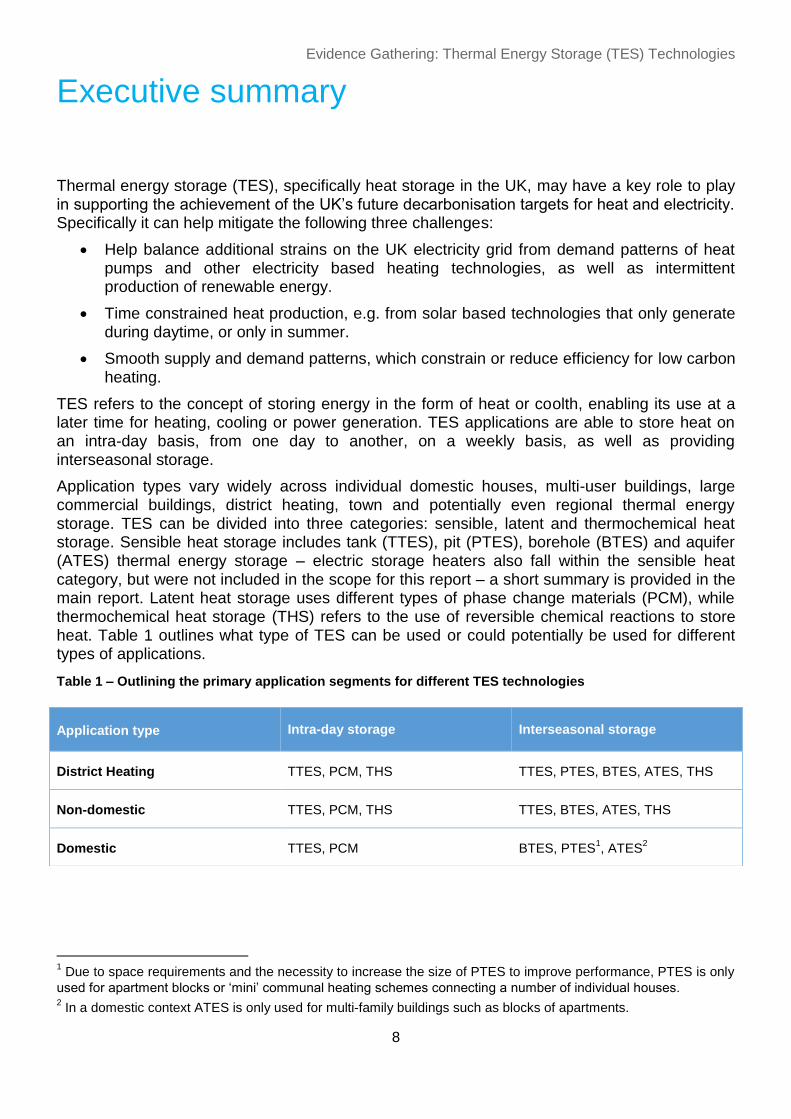
Application types vary widely across individual domestic houses, multi-user buildings, large commercial buildings, district heating, town and potentially even regional thermal energy storage. TES can be divided into three categories: sensible, latent and thermochemical heat storage. Sensible heat storage includes tank (TTES), pit (PTES), borehole (BTES) and aquifer (ATES) thermal energy storage – electric storage heaters also fall within the sensible heat category, but were not included in the scope for this report – a short summary is provided in the main report. Latent heat storage uses different types of phase change materials (PCM), while thermochemical heat storage (THS) refers to the use of reversible chemical reactions to store heat. Table 1 outlines what type of TES can be used or could potentially be used for different types of applications.
Table 1 – Outlining the primary application segments for different TES technologies
1 Due to space requirements and the necessity to increase the size of PTES to improve performance, PTES is only
used for apartment blocks or ‘mini’ communal heating schemes connecting a number of individual houses. 2 In a domestic context ATES is only used for multi-family buildings such as blocks of apartments.
Application type Intra-day storage Interseasonal storage
District Heating TTES, PCM, THS TTES, PTES, BTES, ATES, THS
Non-domestic TTES, PCM, THS TTES, BTES, ATES, THS
Domestic TTES, PCM BTES, PTES1, ATES
2

Evidence Gathering: Thermal Energy Storage (TES) Technologies
9
We have carried out in-depth research looking at the range of different thermal energy storage technologies in the UK, as well as gaining an understanding into experiences and learning from other European countries. The aim is to inform a wide audience about heat energy storage products building up a picture of what we currently know and where the gaps are in the research. The specific questions addressed include:
Provide an understanding of the difference between various TES technologies and evaluate their technological potential.
A review of the current UK market and outline of the availability of products and the types of projects realised.
The costs of different TES and what the future cost trajectory may look like.
The primary market barriers which influence the current market and future potential of TES.
Review of the current evidence available and identification of where gaps exist.
Understanding the different TES technologies
TES includes a wide range of technologies and applications. Throughout the report the different technologies are explained and the technological differences and application cases will be compared. Different TES technologies have specific application cases and storage timeframes. For example, some technologies, such as PTES are most suitable to be used at large scale (e.g. district heating) and can be used for interseasonal storage; while others like PCM are more suitable for domestic and commercial buildings for intra-day storage.
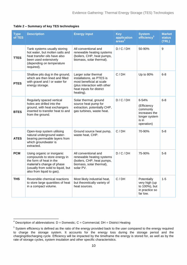
To provide a high level understanding, Table 2 provides a summary of the key TES technologies, their various potential energy inputs (interacting technologies), system efficiency and current market status (using Technology Readiness Level as outlined by the European Commission)3.
3 The European Commission (2013; Horizon 2020 work programme) has defined 9 Technology Readiness Levels
(TRL). For the purpose of providing a basis for the comparison of market status we have adopted the
Commission’s definitions, as found in the Horizon 2020 Work Programme 2014-2015 - General Annex G: TRL 1 – basic principles observed TRL 2 – technology concept formulated TRL 3 – experimental proof of concept TRL 4 – technology validated in lab TRL 5 – technology validated in relevant environment (industrially relevant environment in the case of key enabling technologies) TRL 6 – technology demonstrated in relevant environment (industrially relevant environment in the case of key enabling technologies) TRL 7 – system prototype demonstration in operational environment TRL 8 – system complete and qualified TRL 9 – actual system proven in operational environment (competitive manufacturing in the case of key enabling technologies; or in space)
Evidence Gathering: Thermal Energy Storage (TES) Technologies
10
Table 2 – Summary of key TES technologies
Type of TES
Description Energy input Key application areas
4
System efficiency
5
Market status (TRL)
TTES
Tank systems usually storing hot water, but molten salts and heat transfer oils have also been used extensively (depending on temperature required).
All conventional and renewable heating systems (boilers, CHP, heat pumps, biomass, solar thermal).
D / C / DH 50-90% 9
PTES
Shallow pits dug in the ground, which are then lined and filled with gravel and / or water for energy storage.
Larger solar thermal installations, as PTES is most beneficial at scale (plus interaction with other heat inputs for district heating).
C / DH Up to 80% 6-8
BTES
Regularly spaced vertical holes are drilled into the ground, with heat exchangers inserted to transfer heat to and from the ground.
Solar thermal, ground source heat pump for extraction, potentially CHP, gas turbines, waste heat.
D / C / DH 6-54%
(Efficiency commonly increases the longer system is in operation)
6-8
ATES
Open-loop system utilising natural underground water-bearing permeable layers from which groundwater is extracted.
Ground source heat pump, waste heat, CHP.
C / DH 70-90% 5-8
PCM Using organic or inorganic compounds to store energy in the form of heat in the material’s change of phase (usually from solid to liquid, but also from liquid to gas).
All conventional and renewable heating systems (boilers, CHP, heat pumps, biomass, solar thermal), solar PV.
D / C / DH 75-90% 5-8
THS Reversible chemical reactions to store large quantities of heat in a compact volume.
Most likely industrial heat, but theoretically variety of heat sources.
C / DH Potentially very high (up to 100%), but in practice so far low.
1-5
4 Description of abbreviations: D = Domestic; C = Commercial; DH = District Heating
5 System efficiency is defined as the ratio of the energy provided back to the user compared to the energy required
to charge the storage system. It accounts for the energy loss during the storage period and the charging/discharging cycle. Efficiency will be impacted by the timeframe the energy is stored for, as well as by the rate of storage cycles, system insulation and other specific characteristics.

Evidence Gathering: Thermal Energy Storage (TES) Technologies
11
The market today
Overall, there are two primary TES technologies that have experienced widespread uptake in the UK. In the residential sector electric storage heaters and tank based systems are established. Approximately 1.8 million electric storage heaters are installed in UK homes, while almost 400,000 hot water tanks (above 50 litres volume) are sold annually. Overall there are approximately eleven million hot water tanks installed. Larger TTES systems (>500 litres) are selling low thousands of units each year for large residential or commercial applications. There are tens of systems in the district heating segment, where tanks are usually of a size between low hundreds to thousands of m³. Other systems have seen a much more modest uptake. For underground TES technologies (PTES, BTES, ATES) the number of projects ranges from a few single projects to low tens of installations in the UK.
With regards to emerging TES technologies – PCM and THS – the commercially motivated uptake of systems remains very low for heating applications. The primary development of PCM has been as part of funded research projects, such as BEIS’s Advanced Heat Storage Competition6 (BEIS, 2013). For THS there is currently no market as such, because the technology is primarily tested and evaluated within the academic research community. Table 3 summarises the current UK market status for different TES applications.
Table 3 – Summary of market status for different TES applications in the UK
Type of TES Application UK market today
Sensible heat
storage
Intra-day Approximately 400,000 hot water tanks are sold p.a. in the UK and
the installed base is approximately eleven million.
The installed base of electric storage heaters in residential
buildings is around 1.8 million.
Interseasonal Only used for niche applications – estimated that in total there are
10s of projects (PTES, BTES, ATES).
Latent heat storage
(PCM)
Intra-day A number of players in the UK are investing in R&D of heat
storage applications – likely around 1000s of systems installed
mainly in trial projects.
Interseasonal N/A
Thermochemical
heat storage (THS)
Intra-day Only investigated in a R&D and academic context – no
demonstrator projects were identified in the UK.
Interseasonal
6 Examples from the DECC Advanced Heat Storage Competition include amongst others Sunamp Ltd., University
of Warwick, Phase Change Material Products, Community Energy Solutions, IECHP Ltd. (DECC, 2013).

Evidence Gathering: Thermal Energy Storage (TES) Technologies
12
Cost analysis and future cost development
Capital cost estimates for TES can range from below 0.30 £/kWh for very large interseasonal applications to above 400 £/kWh for very small PCM stores for intra-day storage (as listed in Table 4; throughout the report costs refer to capital expenditure, unless outlined differently). Generally upfront costs progressively reduce as the size of the thermal store increases – meaning that the bigger the store the lower the cost (in terms of £/kWh or £/m³). Cost estimation can prove very difficult and uncertain depending on the TES technology evaluated, for each technology different methods can be adopted for calculating costs. Therefore, where possible this report includes a wide range of capital cost estimates. The high level results are presented in the summary Table 4.
Table 4 – Cost overview for TES technologies analysed in this study
For operation and maintenance costs, there is limited data available. A study from Germany (Solites, 2012) evaluated a number of different TES projects for interseasonal heat storage and found that whilst there is very little monitored data, operating costs could be estimated to be around 0.25% of total investment cost and maintenance cost approximately 1%. Aside from the operation and maintenance of the actual thermal store, further costs for the overall integrated heating system need to be considered. Operation and maintenance of components such as
7 It should be noted that in several reported cases the methodology used for estimating the heat capacity of a
BTES store and for measuring heat retention using sensors in the store, is subject to a high degree of uncertainty,
as well as hydrogeological conditions being different than expected prior to installation thus changing the
performance of the thermal store once operational. 8 Please note ATES costs are provided in £/kW, as the aquifer provides a natural storage medium the boundaries
of the store are difficult to define. The purpose of ATES is to increase the efficiency of heating and cooling, thus the
more meaningful metric used for cost comparison is kW rather than kWh, as this expresses the maximum rate at
which energy can be extracted. When comparing costs in terms of m³ water equivalent ATES is very much
competitive with other underground thermal storage technologies.
Type of TES
(heat storage) District Heating Non-domestic Domestic
TTES <1-150 £/kWh (highly dependent on size, e.g. some
commercial systems may be similar size to domestic) 25 -180 £/kWh
PTES 0.30-0.80 £/kWh N/A N/A
BTES Potentially as low as 0.30 £/kWh (highly dependent on size, and method used for measuring
heat retained in ground)7
ATES
600-1000 £/kW (note ATES size commonly expressed as
maximum heating rate for heat being extracted from well not
the energy stored in aquifer)8
N/A
PCM Unlikely to be used 250-400 £/kWh (potentially as low as 50 £/kWh for large
applications)
THS Potentially very cost effective, but at current state of research very cost intensive and not
ready or economical for commercialisation.

Evidence Gathering: Thermal Energy Storage (TES) Technologies
13
heat pumps and auxiliary heat sources, may be relatively high and thus affect the cost performance of the overall solution.
The cost reduction potential for more established sensible heat storage technologies is limited, but both PCM and THS are expected to see significant cost reductions as R&D advancements are made. Given the relatively early development stage of several types of TES, in order to increase the level of confidence in future cost scenarios, it would be necessary to carry out additional research focused specifically on the cost development trajectory of TES.
Several technologies are either in early stages of commercialisation or not yet ready for market in the UK (e.g. PCM, THS). Therefore accurate cost trajectories are very difficult to provide as unforeseen step change developments may occur that significantly reduce costs.
Technologies such as TTES, PTES and BTES are unlikely to see significant cost reductions, because much of the supplementary technology / installations techniques are well proven (e.g. drilling of boreholes, excavating, lining and insulation for PTES,
manufacturing and installing water tanks).
Future market development of TES in the UK
With regards to the future potential TES deployment in the UK two scenarios are outlined:
‘Business as usual’ development where TES in the UK would continue on its existing path.
An alternative scenario for the decarbonisation of heat and use of TES for electricity time shifting.
The two different scenarios largely depend on a number of key variables. From an isolated technology perspective there should be very little constraint for bringing the majority of the technologies shown in this report to market. However, to drive the UK TES market further, two factors need to be present: a stronger understanding of and confidence in the various technologies beyond hot water tanks and storage heaters; and price signals that enable TES to deliver value to customers. In summary the two scenarios outline the following deployment to 2025:
Table 5 – Summary of future TES market development
Business as usual scenario Growth scenario
District
Heating (DH)
Uptake of TTES in most new DH and
some retrofit efforts, primarily used for
intra-day / daily balancing.
All new installations and majority of existing DH
retrofitting using TTES. Trials of interseasonal
TES for DH applications with solar thermal.
Non-domestic
Stable market for TTES and potential
emergence of PCM trials. Slowly
increasing, but low number of projects
using interseasonal TES.
Growing market for TTES. Development of more
novel TTES applications using other materials
than water. Growing uptake of interseasonal
storage using ATES and BTES. Emergence of
early demonstration trials for THS applications.
Domestic
Annual TTES product sales remain
relatively stable / slow decline; limited
uptake of PCM stores replacing or being
integrated in hot water cylinders. Limited
applications of solar / ground source
heat pumps coupled BTES installations.
Growing market for TTES based on growing
electric heating (and possibly CHP) take-up and
electricity price signals for flexibility. Wider uptake
of PCM based products to overcome space
constraints. Different types of BTES becoming
more established in newbuild.

Evidence Gathering: Thermal Energy Storage (TES) Technologies
14
Key research gaps
Throughout the course of this project, a number of gaps in the available knowledge and level of research were identified. Five key themes were identified and these can broadly be summarised as follows:
Commercialisation challenges
Uncertainty around future cost reduction
Uncertainty around performance of TES technologies
Lack of interseasonal heat storage knowledge in the UK
Uncertainty around carbon savings and benefits
o Evaluating whether TES increases carbon emissions, because all storage systems have losses
o Better understanding the degree to which TES can support electricity sector decarbonisation
The following areas where additional research could be undertaken to enhance understanding and support the integration of TES into the wider strategy for meeting the UK’s decarbonisation targets and ensuring security of energy supply were identified:
Carrying out real world field trials for interseasonal TES, PCM and thermochemical heat storage to fully understand and evaluate technological performance.
Further advancing R&D in latent and thermochemical heat storage to support their development and future commercialisation.
Fully evaluating how different TES technologies, besides hot water tanks, can be integrated into the existing UK heating infrastructure.
Further analysing the use of thermal storage to optimise the sizing and efficiencies of boilers and other heating systems.
Better understanding how electric heating and CHP can be used with TES to provide benefits to the wider electricity system.

Evidence Gathering: Thermal Energy Storage (TES) Technologies
15
1 Opportunities, applications and value of Thermal Energy Storage (TES)
1.1 Uses and potential of TES
Meeting the UK’s 2050 climate change target will require a near complete decarbonisation of heat (Committee on Climate Change, 2015).
The Committee on Climate Change identifies electrically driven heat pumps as a promising option to help meet this target, together with district heating (otherwise known as heat networks) served by low-carbon sources of heat. While it expects energy efficiency to play a key role in decarbonising heat, renewable and low-carbon forms of heat will be required to reduce the carbon intensity of the UK’s heat supply.
Challenges for the decarbonisation of heat
Currently the penetration of renewable and low carbon heat sources in the UK is limited. The balance between different future heat sources is unknown, but could comprise significant growth in technologies such as electric heating (including heat pumps), solar thermal, and combined heat and power. Technologies such as this would bring a number of challenges including:
Additional strains on the UK electricity grid from demand patterns of heat pumps and other electricity based heating technologies, as well as intermittent production of renewable energy.
Time constrained heat production, e.g. from solar based technologies that only generate during daytime and produce most energy in the summer.
Mismatches between CHP operation and the needs of the electricity sector.
All the above challenges could be mitigated through the storage of energy. Therefore, TES, specifically heat storage in the UK, potentially has a key role to play in supporting the achievement of the UK’s future decarbonisation targets for heat and electricity.
Six key applications for TES
We define six key applications for TES based on the deployment type being distinguished by
two key variables as outlined below:
Type of location / application, i.e. district heating / industrial, non-domestic and domestic.
Duration and discharge cycles. For the purpose of this analysis these are defined as intra-day storage and interseasonal storage.

Evidence Gathering: Thermal Energy Storage (TES) Technologies
16
Thermal Energy Storage
District Heating
Heat Pumps
CHP
Biomass
Solar PV (e.g. with diverter)
Solar Thermal Power
These two variables will not capture every single potential use of TES technologies (e.g. potential ability to use for multi-day or weekly cycles), but they provide an illustration of the two primary application purposes.
Table 6 – Characterisation of key TES applications
Notably interseasonal heat storage in the UK is currently most applicable for commercial
buildings or large apartment blocks with reversible ground source heat pumps, as well as district heating applications. While there are developments of interseasonal heat storage for domestic and multi-family buildings in the UK as outlined within this report, the current market developments justify the focus on four key application areas, highlighted in Table 6. For the purpose of this study the domestic sector is defined as residential houses with individual installations, whereas non-domestic includes commercial buildings, office buildings and large apartment blocks and heat networks connecting individual buildings (residential and commercial) are captured under the district heating category.
1.2 TES and other (renewable) energy technologies
TES closely interacts with a range of heating technologies and can improve the efficiency of operation and help increase the energy production of renewable and other (low carbon) generation technologies.
Application type Intra-day storage Interseasonal storage
District Heating Addressed in report Addressed in report
Non-Domestic Addressed in report Limited applicability
Domestic Addressed in report Limited applicability
Figure 1 – Heating technologies interacting with TES

Evidence Gathering: Thermal Energy Storage (TES) Technologies
17
There are three primary purposes for coupling TES with different renewable and other (low carbon) generation technologies which can play a role in supporting long-term emission reduction goals:
Time shifting of heat demand and production
Time shifting of electricity demand
Increasing the performance of specific heating technologies
Time shifting of heat demand and production
TES supports the shift of heat demand and production. This refers to the time when heat is produced by both conventional and renewable heating systems, such as boilers or heat pumps. This will closely be linked to increasing system performance or comfort – i.e. delivering hot water or heating from a store when the demand may not be met through the operation of the system. Therefore what is required under this scenario is an intra-day or daily balancing using a heat store.
Common applications include the combination of conventional (gas or oil boilers) and renewable heating systems (e.g. heat pumps, solar thermal and biomass boilers) in the domestic space, as well as the coupling with CHP or industrial heat pump systems in the commercial or district heating segment.
Secondly, very large stores can provide interseasonal storage of heat9, with the most common application for this being the integration of solar thermal into community or district heating schemes, storing heat from the summer months for use during winter.
Time shifting of electricity demands
For time shifting electricity demand, power would be converted into heat in order to be stored and used at a later time to provide e.g. space heating. Another application would be for combined heat and power, which could operate when the electricity grid requires power, rather than being driven by end-user heat demand. Most logical is the use on an intra-day or daily basis. A range of existing and emerging TES technologies could enable this: storage heaters, various tank based systems, phase change materials.
Some time-of-use price signals are already available to customers (such as Economy 7). However these only capture part of the value of electricity system flexibility, and are static. There is already some further activity around flexible heating that uses or produces electricity in the UK. This includes Distribution Network Operator led projects such as the Customer Led Network Revolution; flexibility using electric storage heaters in the UK (as developed by VCharge); some larger CHP plants are already using thermal stores to operate more flexibly for the electricity grid; and companies such as PassivSystems are exploring flexible heat pump
9 To provide context, interseasonal heat storage refers to the concept of absorbing heat continuously during the
summer and releasing it during the winter – it is not common in the UK but is becoming increasingly common
elsewhere in northern Europe (specific examples are listed throughout this report). Large thermal stores,
particularly for district heating, enable a proportion of winter heating to come from active solar thermal arrays and
also allow other ‘waste’ energy sources including low-grade heat from CHP or industrial sites to contribute to winter
heating demands.
Large tanks, boreholes, pits and aquifers have also all been demonstrated for interseasonal storage of passive
solar gain (heat removed from buildings by air conditioning systems) as described in the relevant sections of
chapter 3. The use of interseasonal storage for individual commercial buildings using solar heat or ground source
heat pumps (for heating and cooling) may grow significantly, if future non-domestic building regulations require
close to zero-carbon buildings.

Evidence Gathering: Thermal Energy Storage (TES) Technologies
18
operation. In years to come more dynamic, sophisticated price signals may emerge. End-customers could then receive value from providing services to the electricity system.
Using TES to absorb electricity and output heat may become a significant driver of thermal energy storage. Time shifting of electricity typically requires just hours of storage. Domestic thermal stores could be used, for example, to turn electric heat pumps on or off by storing hours worth of heat demand. Domestic stores, including existing hot water tanks, could also be used to ‘dump’ excess electricity produced by wind or solar generators with zero marginal running costs when electricity demand is low, or to provide short-term ancillary services to the National Grid via aggregators.
Increasing the performance of other energy technologies
Lastly, thermal stores have a significant role in improving the efficiency of heating and cooling technologies. For example, dumping heat (in summer) and coolth (in winter) into aquifers or boreholes can be used to improve the performance of ground source heat pumps that provide heating and cooling for buildings. In this case thermal energy is technically stored, but the
primary effect or purpose of the storage is not the shifting of demand, but the improved efficiency. This provides to specific advantages:
(i) Separating the production of heat from demand so it can be met by intermittent sources of heat.
(ii) Smoothing the demand for heat so that low carbon heating technologies can be operated more efficiently and sized cost effectively.
Understanding the interaction between thermal energy storage and other (renewable) heating systems is important for evaluating the overall benefit of the wider adoption and intelligent use of different TES technologies - specifically understanding how TES can improve efficiencies of other energy technologies such as heat pumps. While this is an area where further research could be conducted, it falls outside of the scope for this study.
The importance of controls
Enabling all three of the outlined purposes – time shifting of heat demand and production, time shifting of electricity demand and increasing the performance of other heating and generation technologies – is the use and integration of intelligent control systems.
With regards to the time shifting of electricity, intelligent interfaces are a specific requirement for enabling real time monitoring and fast response of the thermal stores. Furthermore, with regards to increasing the efficiency of CHP or heat pump technologies, intelligent control systems improve the overall system optimisation potential. Without the development of smart controls TES may play a much less significant role in decarbonising the heating sector and providing network support for renewable integration. The area of controls has not been a focus of this research but we note the necessity of intelligent control systems, and in general observe this is an area with some activity today from companies such as PassivSystems, VCharge and IE-CHP, but with much of this activity at a relatively early stage.
There remain barriers with regards to cost and integration of intelligent controls particularly for retrofit solutions. However, based on current technological developments, uptake of smart controls both in the residential and commercial / industrial sectors and increasing sophistication of systems this is unlikely to be major barrier to effective use of TES in the future.

Evidence Gathering: Thermal Energy Storage (TES) Technologies
19
1.3 Current and future cost potential of TES
Cost analysis of TES
Throughout the research it was clearly observable that capital costs show a progressive reduction (on £ per kWh or m³ basis) as system size increases. This is true for all TES technologies. For tank based systems, the cost of tank material and insulation decreases per m3
of water stored, and for underground sensible heat stores high fixed costs (of boreholes or wells) can be spread across for large installations (see Figure 2). It is still true, but less pronounced, for PCM and THS, where economies of scale will reduce the cost of PCM and thermochemical materials as well as reducing the balance of plant cost per kWh of storage.
Cost variation of the storage medium
Across all technologies the operating costs are low compared to the upfront cost.10 While typically the storage medium itself shows very low costs for sensible heat storage (i.e. water, earth, rock), it is the surrounding component and installation expenditure that can drive costs of
all types of TES. For TTES and PTES this includes the store’s container or insulating materials respectively, while for BTES and ATES significant costs can be associated to the drilling of boreholes and wells. On the contrary PCM and THS materials can be more expensive, driving the overall capital cost points for these stores.
System components can add significant cost, as can installation
Additionally, across the different TES technologies there is often high cost related to additional components such as heat exchangers, control systems and required pumps. Installation costs remain a factor, even for small systems that may require qualified heating system installers. For very large and interseasonal TES, where a large proportion of the upfront expenditure is related to the actual installation of the system, the upfront costs prove to be an even greater barrier to the implementation of projects.
Operation and maintenance cost for the thermal store itself are relatively low
There is limited data available, but a study from Germany (Solites, 2012) evaluated a number of different TES projects for interseasonal heat storage and found that operating costs could be estimated to be around 0.25% of total investment cost and maintenance cost approximately 1%. Additionally, maintenance costs of the overall integrated heating system, including components such as heat pumps and auxiliary heat sources as well as the thermal store, may be relatively high.
Specific storage costs typically reduce as storage capacity increases
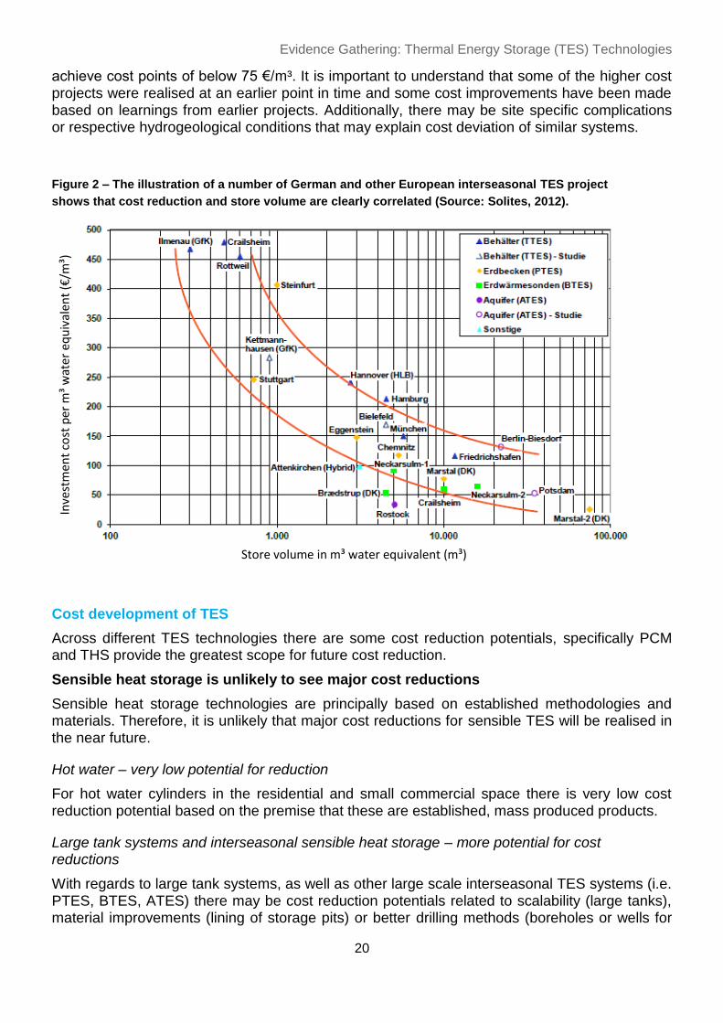
Progressive cost reduction based on the increase in size is particularly relevant to large scale, interseasonal TES technologies and this subject has been widely commented on across the evaluation of specific projects (see for example Solites, 2012; Jensen, From & Sørensen, 2015; Miedaner & Sørensen, 2015). The graph below plots a number of different TES projects from across Germany and selected other continental European projects. The results presented in
Figure 2 show the most comprehensive illustration of the correlation between project cost and volume of the store. Based on the graph the projects above 10,000 m³ show costs of below 150 € / m³. With all types of interseasonal storage shown, size / volume of the storage systems is important in the cost analysis. ATES, BTES and PTES installations of above 15,000 m³ can
10
Please note for the purpose of this analysis, we do not include standing losses of the heat store as an operating
cost. However, it is noteworthy that even when losses are included the capital expenditure still remains
proportionally more significant than the operational costs.
Evidence Gathering: Thermal Energy Storage (TES) Technologies
20
Figure 2 – The illustration of a number of German and other European interseasonal TES project
shows that cost reduction and store volume are clearly correlated (Source: Solites, 2012).
Inve
stm
ent
cost
per
m³
wat
er e
qu
ival
ent
(€/m
³)
Store volume in m³ water equivalent (m³)
achieve cost points of below 75 €/m³. It is important to understand that some of the higher cost projects were realised at an earlier point in time and some cost improvements have been made based on learnings from earlier projects. Additionally, there may be site specific complications or respective hydrogeological conditions that may explain cost deviation of similar systems.
Cost development of TES
Across different TES technologies there are some cost reduction potentials, specifically PCM and THS provide the greatest scope for future cost reduction.
Sensible heat storage is unlikely to see major cost reductions
Sensible heat storage technologies are principally based on established methodologies and materials. Therefore, it is unlikely that major cost reductions for sensible TES will be realised in the near future.
Hot water – very low potential for reduction
For hot water cylinders in the residential and small commercial space there is very low cost reduction potential based on the premise that these are established, mass produced products.
Large tank systems and interseasonal sensible heat storage – more potential for cost reductions
With regards to large tank systems, as well as other large scale interseasonal TES systems (i.e. PTES, BTES, ATES) there may be cost reduction potentials related to scalability (large tanks), material improvements (lining of storage pits) or better drilling methods (boreholes or wells for

Evidence Gathering: Thermal Energy Storage (TES) Technologies
21
ATES), as well as more general learning by doing. Specific cost reduction potentials have been observed for newer generation systems, where learnings were based on earlier trials of similar technologies. For example a study carried out in Germany (Solites, 2012) found that comparing interseasonal storage with the same performance parameters showed that newer installations (e.g. PTES in Eggenstein) were up to 30% cheaper than their predecessors. Therefore, as the applications for interseasonal stores become more widespread, it allows for the assumption that costs will fall. However, for different TES technologies, the primary cost reduction driver remains the volume of the store.
PCM – significant cost reduction potential
For other technologies, such as PCM, which are currently emerging for some niche applications, there is significant cost reduction potential as R&D efforts and increasing manufacturing volumes continue to reduce prices for materials and related components such as heat exchangers.
Importantly there are a number of manufacturers and technology developers exploring how high
performing PCM based products can be realised at a cost-effective price. We expect to see more cost-effective PCM based products experience wider uptake within the next two to five years, although improvements will be needed to ease of installation for and flexibility of PCM products before a mass-market deployment is feasible.
THS – cost reductions are uncertain as technology is immature
R&D efforts will continue to explore and improve the potential of this technology. However, based on the current level of advancement, the timeframe and scale of these reductions is not clear.

Evidence Gathering: Thermal Energy Storage (TES) Technologies
22
2 Characterising TES technologies
2.1 Introduction to TES
TES refers to the concept of storing energy in the form of heat or coolth enabling its use at a later time for heating, cooling or power generation.
This section introduces the three types of TES, describes each type, and then presents a comparison in tabular format.
Varied applications for TES
TES is an established concept for balancing the mismatch in demand for and supply of heating or cooling, offsetting differences in time and magnitude of heat / cooling production. TES can help improve system performance by smoothing supply and demand, system temperature fluctuations and improving the reliability of the heat / cooling source. TES applications are able to store heat on an intra-day basis, from one day to another, on a weekly basis, as well as providing interseasonal storage. Application types vary widely across individual domestic houses, multi-user buildings, large commercial buildings, district heating, town and potentially even regional thermal energy storage.
Temperature is a key property of thermal energy storage
The key property of heat storage is the temperature, which can be distinguished into low-temperature heat or high-temperature heat. Low-temperature heat storage usually refers to temperatures below 100ºC and is primarily used for storing energy as hot water in domestic and commercial buildings. High-temperature heat storage is most commonly used for a wide range of commercial processes, chemical engineering and in district heating schemes (temperature 100-150ºC), especially when linked to industrial plants. Additionally, heat of above 300ºC may be used in industrial and power processes.
Three main categories of thermal energy storage
When characterising TES, one differentiates between three main categories
(i) Sensible heat storage
(ii) Latent heat storage
(iii) Thermochemical heat storage
(i) Sensible heat storage
Sensible heat storage is by far the most established and commercially used type of TES. Tank thermal storage (TTES) storing hot water and electric storage heaters are

Evidence Gathering: Thermal Energy Storage (TES) Technologies
23
particularly advanced and well established in the UK. The majority of installed and working TES installations are based on the principle of sensible heat storage.
Describing sensible heat storage
The concept is based on the principle of energy being stored (or extracted / exchanged) in a solid or liquid, which changes temperature, but not its phase and no chemical reaction takes place either. Typical materials used for sensible heat storage are liquids such as water, heat transfer oils and types of molten salts. Further material types include solids such as concrete, pebbles, granite, rocks, earth etc. For charging, heat from a higher temperature source is added to the store and in order to discharge, the heat is extracted to a lower temperature sink, subsequently decreasing the temperature in the store again.
Sensible heat storage is widely available in the form of hot water tanks
Sensible heat storage is by far the most commercially advanced type of thermal
energy storage, with the primary type being tank based systems storing hot water. These are used for both small scale residential, as well as larger commercial, industrial and district heating applications. In these contexts tank based systems usually provide intra-day / daily heat storage, however, tank based systems have also been developed for interseasonal thermal energy storage.
Other forms of sensible heat storage include pits, boreholes and aquifers
Three other sensible heat storage technologies, which are primarily used to provide interseasonal heat storage are considered in this report. These are Pit TES (PTES), Borehole TES (BTES) and Aquifer TES (ATES). These technologies (together with large underground water tanks) are commonly summarised as underground thermal energy storage. The four different types of sensible heat storage suitable for interseasonal heat storage are illustrated in Figure 3.
Figure 3 – Illustration of different TES technologies currently used for interseasonal
heat storage (Source: Miedaner & Sørensen, 2015)
Evidence Gathering: Thermal Energy Storage (TES) Technologies
24
Electric storage heaters – common in the domestic sector
Another very common form of sensible heat storage is through electric storage heaters. These are a common heating technology used in the UK domestic sector. An estimated 1.8 million homes in Great Britain use storage heaters11, commonly running on Economy 7 electricity tariffs. Most homes with storage heaters will also have some direct electric panel heaters or bathroom heaters, along with a direct electric hot water tank. Electric storage heaters typically consist of ceramic blocks, which are heated to temperatures of up to 600˚C.
Storage heaters typically run at night, storing heat in a material with a high specific heat capacity. Storage heaters used to be ‘static’ – the heat would gradually be discharged from the storage medium through the day with no or little control. Additional direct electric input from a boost heater is then sometimes necessary in the evening period before the night time charging period.
Newer storage heaters aim to get towards the high response rates of direct electric heating. They achieve this response rate by using very high levels of insulation to avoid heat leaking out, a fan to drive heat from the storage medium into the room, and controls to manage the level and timing of heat discharge into the building. While not explicitly considered in this study, the case study on Dimplex storage heaters provides evidence on performance and technological potential for electric storage heaters in the UK.
Case Study – Dimplex Storage Heaters
Dimplex are a manufacturer of storage and heating solutions selling approximately
150,000 electric storage heaters per year. Their latest storage heater product (branded
Quantum) claims a responsiveness close to the level of direct electric heaters. This
responsiveness is achieved by using microporous insulation material, a high density iron
ore for the storage material, a reduction in the storage temperature to 550ºC, and efficient
fans. Dimplex claims that this enables them to source around 90% of heat from off-peak
periods for typical applications.
Storage capacity ranges from under 10 kWh to over 20 kWh, with a 20 kWh Quantum
storage heater costing around £800 installed (the manufacturer selling price is
approximately half this amount) according to the company. This gives an effective storage
cost of £40/kWh for the whole product. Direct electric panel heaters can cost around half
this amount, giving an effective marginal cost of storage for direct electric heat in the
region of £20/kWh.
Electric storage heaters are not explicitly considered in this study, but they could become providers of valuable electricity balancing services to network operators.
11
There is a lack of robust annual sales data specifically analysing electric storage heaters and
electric heating in general. The data provided (approx. 1.8 million) is based on figures provided
through industry interviews and Delta-ee analysis of various housing stock surveys such as English
and Scottish Housing Surveys, DECC Housing Energy Fact File and Department for Communities
and Local Government.

Evidence Gathering: Thermal Energy Storage (TES) Technologies
25
The scope of the project outlines the goal to understand how different TES technologies can interact with conventional and renewable heating systems and what the potential for the deployment of TES is in the UK. Electric storage heaters are in a sense both a conventional heating source and heat storage medium. Additionally, they have gradually become less common and as such were excluded from the study’s scope. However, with a large installed base the use of electric storage heaters for electricity balancing could be explored further, outside of this report.
Thermal mass of buildings
Another form of sensible heat storage, which is present in all enclosed structures, is thermal mass of buildings. The internal structure of buildings, and to a small extent the contents, warm up and cool down with a lag following input (or loss of) heat to the internal air. In all buildings this lag helps to balance minute-by-minute and hour-by-hour temperature fluctuations, and in buildings with high thermal mass (such as old stone-built houses) day-night temperature fluctuations can be significantly reduced.
Use of thermal mass to store heat and coolth is an important component of architectural design, particularly in hot countries. Modern buildings should be designed to make optimal use of their thermal mass, but the interactions between insulation and thermal mass are not simple and some modern buildings have very low thermal mass, which can necessitate higher capacity heating or cooling systems to meet more ‘spikey’ demands. Some modern buildings, particularly schools and office buildings employing natural ventilation techniques, are designed with high thermal-mass materials in optimal locations to store daytime solar gain or night-time coolth.
There is generally an interest across different building segments to actively manage the temperature of building materials to reduce day-night fluctuations, for example by running night-time air conditioning through exposed concrete beams that will then remain cool during the day.
Thermal mass of buildings is not considered in the rest of this report. Generally this can be attributed to the limited retrofit potential of heat storage through thermal mass in the UK housing stock. Furthermore, despite research to use concrete for storing solar thermal heat – e.g. the Masdar Institute research pilot testing 2x500 kWh thermal stores using solid-state concrete (Bergan & Greiner, 2014), it does not provide a storage solution which can be actively managed to provide flexibility from buildings in the UK. Attempts to use PCM within building materials (e.g. plaster boards) are analysed separately in Chapter 3.6.
(ii) Latent heat storage
A latent heat store refers to the concept of storing energy in the form of heat in the material’s change of phase most commonly from solid to liquid, but the change of phase from liquid to gas is also usable.
Phase change materials – an introduction
The most explored latent heat concept uses phase change material (PCM), which melts at a specific temperature and pressure. Typically the heat is stored within a

Evidence Gathering: Thermal Energy Storage (TES) Technologies
26
Figure 4 – Schematic illustration of
thermochemical energy storage
(Source: ECN, 2013)
very narrow temperature range. This can give the technology an advantage for applications that use heat with small temperature differences, for example providing heat pumps with heat at a constant temperature (e.g. ice water storage). In this circumstance PCM can be advantageous over sensible heat stores in terms of potential energy storage density, required store volume and significantly lower storage losses. The very narrow temperature range of PCM stores is also a major shortfall compared to sensible heat storage, which is likely more economical for applications that allow for larger temperature differences.
Material choices for phase change
A wide range of materials can potentially be used and they are largely explored in a research / academic context with few commercial products emerging (for more information see for example Eames et al., 2014; IEA SHC Task 42; IEA SHC Subtask C: PCM). Some further advanced solutions use aqueous salt solutions and other examples include the use of ice-slurries for cooling purposes in commercial or industrial buildings. One of the key drawbacks of latent heat stores using PCM is the low thermal conductivity of many of the materials used. Therefore an effective heat transfer must be achieved, often increasing material costs for components such as heat exchangers.
(iii) Thermochemical heat storage (THS)
Thermochemical heat storage (THS) is the commercially least advanced thermal storage technology. THS refers to the use of reversible chemical reactions to store large quantities of heat in a compact volume. Using different chemical reactants (usually two liquids or a solid and a vapour), the material breaks down as heat is applied and the separated parts are then stored. As the components are then recombined heat is released (see Figure 4). The energy storage density and capacity is dependent on the temperature, chemical and physical properties of the materials used.
Opportunities for THS
THS offers some significant advantages: THS generally has a much higher energy density than other thermal storage technologies, as well as being able to store the separated reactants for a long period of time without causing high or any degradation of the energy stored. Thus THS is able to provide efficient interseasonal storage without any significant heat losses. However, there are a number of limiting factors in the residential space, depending on the material and technology used. Examples include uncertainty with regards to reliability, potential toxicity, safety concerns, system lifetime, relatively high cost and issues around recyclability. Therefore the most likely future applications of THS are within larger commercial or industrial solutions.

Evidence Gathering: Thermal Energy Storage (TES) Technologies
27
Current status – primarily at R&D stage
So far THS has been primarily evaluated in a theoretical environment and it is not clear if in-situ it is capable of delivering expected results. Significant gaps in the research remain, for example, system and materials design, as well as performance in real-life applications and widespread testing of different thermochemical technologies. In summary THS remains far from commercial realisation in the UK and elsewhere – exemplified by the fact that there are no demonstrator plants in the UK. Additionally the current test projects in other countries have been run by technology research institutes aiming to prove the capability and performance of THS, rather than aiming for commercialisation of systems. A significant amount of time and research will be required to further develop demonstration plants and projects. It is thus unlikely that THS will experience any significant market uptake within the next 10 years.

Evidence Gathering: Thermal Energy Storage (TES) Technologies
28
Table 7 – High level overview, description and comparison of different thermal energy storage
technologies (detail is provided in technology analysis that follows)
Category Type of TES
Description Key advantages Disadvantages
Sensible heat storage
TTES
Tank systems usually storing hot water, but molten salts and heat transfer oils can also be used.
Established and proven
Scalable
Usable for wide range of applications
Cost effective
Space requirements
Smaller stores have higher heat loss rates and are not designed to store heat over long periods of time
PTES
Shallow pits dug in the ground, which are then lined and filled with gravel and / or water for energy storage.
Potential very large storage capacity
Interseasonal potential (e.g. solar heat storage)
Low energy density
Not suitable for built-up areas
Potential land cost constraints
BTES
Regularly spaced vertical holes drilled into the ground, with heat exchangers inserted to transfer heat to and from the ground (closed loop system).
Interseasonal potential (e.g. solar heat storage)
Relatively small excavation requirements
Relatively low efficiency
Limited charging and discharging capacity
ATES
Open-loop system utilising natural underground water-bearing permeable layers from which groundwater is extracted.
Efficient provision of heating and cooling
Easily integrated into building design, thus small land footprint
Hydrogeological restrictions
Balancing of heat input and extraction
Limited to places where extraction is possible
Latent heat storage
PCM Using organic or inorganic compounds to store energy in the form of heat in the material’s change of phase (usually from solid to liquid, but also from liquid to gas).
High energy density
Low volume of store
Constant temperature during charging and discharging.
Relatively immature technology in the domestic segment
Limited availability of suitable PCM materials with desired melting points
Thermo-chemical heat storage
THS Reversible chemical reaction to store large quantities of heat in a compact volume.
Very high energy density
Long term storage without degradation
Very far away from market commercialisation
Lack of real world proof of potential performance

Evidence Gathering: Thermal Energy Storage (TES) Technologies
29
2.2 Current market status of TES in the UK
Table 8 – Current status of TES technologies in the UK by application
Type of TES /
common
timeframe in UK
Current market status in the UK
Domestic Non-domestic District Heating
Tank thermal
energy storage
(TTES)
Intra-day
Widespread use in the
domestic sector for hot
water storage (installed
base of ~11 million
homes)12
Widespread use for
commercial and
industrial applications
Widespread use for
district heating
applications
Pit thermal
energy storage
(PTES)
Interseasonal
No use in domestic
sector
One project identified in
the UK
No projects identified in
the UK (projects in
Denmark)
Borehole thermal
energy storage
(BTES)
Interseasonal
Very few installations in
the UK (low 10s)
Low number of
installations carried out
(approximately low 10s)
by a number of UK
based businesses
No projects carried out in
the UK (examples from
Denmark and Germany).
Aquifer thermal
energy storage
(ATES)
Interseasonal
No use in domestic
sector (for single family
buildings)
Low number of projects
(<10) in the UK for
commercial buildings /
apartment blocks
No projects in UK (some
applications e.g. in the
Netherlands)
Phase change
materials (PCM)
Intra-day
Some industry R&D for
domestic PCM products.
Primarily trial projects,
with one product in the
UK close to market
Limited R&D activity for
specific applications,
with different concepts
explored across Europe.
Limited R&D activity for
specific applications
Thermochemical
heat storage
(THS)
Intra-day /
Interseasonal
Early stage research
(primarily in academia) –
unlikely to be used in
domestic sector
Early stage research
(primarily in academia)
Early stage research
(primarily in academia)
12
Combi boilers account for the majority of domestic boiler replacements in the UK, even though
anecdotal evidence suggests they only account for around half the installed base. This implies the
installed base of hot water tanks is declining. Annual sales of hot water tanks are reported by the Hot
Water Association to be stable.

Evidence Gathering: Thermal Energy Storage (TES) Technologies
30
3 Methodology
3.1 Research and analysis
The project methodology was centred on four key activities in order to provide a robust analysis of the evidence base on thermal energy storage technologies, which was synthesised to produce the final report. Prior to conducting external research the extensive existing expertise from within the project team was utilised. This formed a crucial aspect of identifying and prioritising both primary and secondary sources of evidence for the further research stages. Figure 5 outlines the process of the research conducted for this study.
Extensive secondary research analysing existing literature was then conducted – e.g. academic literature, commercially focussed publications, product data sheets and project case studies, as well as conference presentations and publications.
Following the review of literature and identification of key gaps, primary research was carried out consisting of detailed telephone conversations with thermal energy storage manufacturers, technology developers, technology installers, relevant industry associations, key industry individuals, research institutions etc.
As part of the above process the evidence gathered was reviewed and challenged to assess its robustness wherever possible, and identified gaps, conflicts and potential conflicts in the evidence base.
All aspects of the research were crucial for supporting the evidence gathering on thermal energy storage. The main areas outlined by BEIS to form the core body of the research are outlined below:
Technology information and state of technological development
Market status
Product and project review
Current and future costs
Future market potential
Barriers to deployment
Analysis and discussion of key gaps
Consolidate internal
expertise
Desk based research
Product & project review
Industry interviews
Figure 5 – Outline of the research process

Evidence Gathering: Thermal Energy Storage (TES) Technologies
31
Table 9 highlights the key activities for each research step.
Table 9 – Outline of activities for different research steps and the focus of research
Desk based research Product & project
reviews
Industry interviews
Activities
Analyse publically
available information
Review of synthesis
reports
Review of academic
research
Access to manufacturer
/ project developer
websites
Product catalogues and
brochures
Project presentations
and reviews
Telephone interviews
with key stakeholders
Focus on manufacturers
and project developers
Research
focus
Performance
Cost analysis
Research gaps
Technology barriers
Performance
Cost data
Technology status
Technology
development
Market potential
Barriers
Performance
Research / technology
gaps
Literature Review
A large number publications from academic and lab-based research was reviewed, as well as commercial and conference presentations. In total over 50 such publications were reviewed, as well as a large number of key web resources, such as industry associations, research institutes, IEA annexes and working groups. Publications reviewed included wider synthesis studies, as well as specific academic journals. In addition to research of UK and English language documents, German language documents were also reviewed enabling the inclusion of evidence from widespread research activity and knowledge on TES in Germany. The key focus for this step was to gather evidence on technology performance and current status, cost analysis and scenarios, technology barriers and key gaps in the knowledge.
Product and project reviews
Using the wider literature review, information on product and different TES projects was collated from manufacturers, project developers and industry associations. The key sources for this were product brochures, technical and installation brochures, website information, project presentations, project reviews and direct contact with stakeholders along the value chain. Direct contact and conversations with different stakeholders proved to be a key resource for gaining some of the most meaningful information. For specific products or technologies not explicitly considered in the main body of this research – i.e. electric storage heaters and thermal mass of buildings – evidence is provided in separate ‘case study’ text boxes highlighting a specific product or use identified throughout the research.

Evidence Gathering: Thermal Energy Storage (TES) Technologies
32
Industry interviews
Overall 23 key stakeholders (see List of Research Conversation, page 83) were interviewed for this study. Interviewing thermal energy storage manufacturers, technology developers, technology installers, relevant industry associations, key industry individuals, research institutions, provided valuable additional evidence to the literature review. Additionally, the interviews critiqued initial findings and the respective market and product / project information. A second round of interviews was used to test, explore and challenge evidence gathered and initial hypotheses. A core focus of the primary research was to speak to commercial organisations, who are close to the market.
The structure of the interviews loosely followed the outline below. Where applicable (subject to the organisation / person spoken to) this structure was adapted appropriately.
1. Background
Information about the organisation
Understanding of product / projects
2. Technology & product
Characteristics of technology, product and / or specific projects
Key applications
Performance data
Deployment and installation specifics
3. Costs and cost trajectory
Current cost
Analysis of capital, operation and maintenance costs
Future cost trajectory
4. Market analysis and barriers
Key market segment for your product / technology
Current market status and overall deployment potential
Expectation of step-changes in market development and technology improvement
Technical barriers (i.e. technical feasibility)
Market barriers (commercial feasibility)
Consumer barriers (e.g. consumer awareness, confidence, trust and uncertainties)
Supply chain challenges
5. Research Gaps
Major gaps in the current level of research
Key gaps for supporting the commercialisation of specific technologies
How to best address gaps

Evidence Gathering: Thermal Energy Storage (TES) Technologies
33
4 Technological analysis of TES
4.1 Introduction to the analysis
This section provides a detailed analysis of performance, technological potential, the current market, technology cost and cost reduction potentials, as well as main barriers to technology uptake.
Each section follows the same principle providing key parameters of the respective technologies in a table format and a subsequent analysis.
4.2 Tank Thermal Energy Storage (TTES)
A range of technologies can be captured under the TTES heading including but not limited to:
Water based domestic thermal stores and buffer tanks
Tank based systems utilising materials such as heat transfer oils and molten salts.
Very large water tanks utilised for balancing intra-day CHP / DH applications and interseasonal heat storage with solar thermal plants.
For smaller hot water tanks one distinguishes between direct and indirect systems. In a direct system the stored fluid and the heat transfer fluid are the same, while in an indirect system they are separate and the heat is used indirectly by means of a heat exchanger. For the analysis of domestic systems this becomes relevant as one compares between (i) thermal stores and (ii) hot water cylinders.
(i) In a thermal store (indirect system) water is heated by passing through a heat exchanger that transfers heat from the thermal store water to the mains or tap water.
(ii) In a hot water cylinder (direct system) the water stored is simply passed through the domestic hot water supply when required.
At present, approximately 11 million homes in the UK have a hot water cylinder or thermal store13. These are used as a buffer to meet peak hot water demand from relatively small boilers or renewable heating technologies. The thermal storage capacity in domestic tanks could also be used to store heat that is transformed from electricity through heat pumps and other electric heating appliances.
13
There is a lack of robust data with regards to the number of residential dwellings with hot water
cylinders. The data provided throughout the report is based on research interviews with industry
stakeholders, as well as data on energy efficiency and combination boilers provided in the English
Housing Surveys. These data points provide the basis for estimating the number of homes with hot
water cylinders.

Evidence Gathering: Thermal Energy Storage (TES) Technologies
34
Table 10 – Summary results for TTES application
Metric Summary of results
Timeframe Small stores used for intra-day / daily cycling
Large TTES provide intra-day / daily cycling and interseasonal storage
Application types Domestic; Commercial; District heating
Market Status / TRL 9
Cost Range from 26 £/kWh to 183 £/kWh14
for domestic systems (large
variation between small thermal stores)
Large scale TTES: cost potentially below 1 £/kWh15,
Cost per m³:
Small domestic: 925 to 2,700 £/m³ 14
Medium TTES (e.g. 300 m³): 360 £/m³ 16
Larger / interseasonal TTES: 91 to 114 £/m³ 17
UK companies /
projects
Large number of manufacturers and developers active in the UK
Technical barriers to
deployment
Space constraints; relatively low energy density; weight (when full), de-
stratification (relevant for larger tanks in particular); system integration
for large tanks; retrofitting of tank based system (both small, but
especially applicable to large systems) if original building design did not
consider installation.
Market barriers Small water tanks: Growing penetration of combination boilers, low
renewable heating uptake to date.
Large TTES: Upfront cost, relatively low number of district heating
schemes in the UK.
Technology interaction Small water tanks: all conventional and renewable heating systems
Large TTES: CHP, biomass, district heating, commercial heat pumps,
large solar thermal, commercial boilers etc.
System efficiency 50 – 90%
14
UK market analysis: 25.58 £/kWh and 925 £/m³ represent low cost 400 litre direct hot water
cylinder, 183.09 £/kWh and 2,700 £/m³ for 300 litre fully integrated thermal store (excl. heating
controls). The cost of domestic units vary widely depending on size, quality and the capabilities of the
hot water cylinder. 15
Please note for ease of use of the tables, all Euro (€) values have been converted into pound
sterling using the current exchange rate of €1 to £0.76. This does not necessarily reflect the exact
cost point achievable in the UK. 16
470 €/kWh (Eames, et al., 2014) 17
120 to 150 €/m³ Based on example store sizes of 12,000 m³ (low cost end) to 5,700 m³ (higher cost
end). Sources: Solites, 2012; Eames, et al., 2014

Evidence Gathering: Thermal Energy Storage (TES) Technologies
35
Tank thermal energy storage using hot water is also established for larger applications. The primary applications for large water tanks are to provide intra-day balancing of CHP and district heating applications, as well as interseasonal storage in combination with solar thermal installations. As such larger hot water tanks are an established technology both in the UK and across Europe. However, unlike smaller water tanks which are manufactured standardised and at volume very large tank based systems will usually be bespoke, meeting specific design requirements and features required for the application. There are more notable R&D efforts and technological advancements in this particular area with new, very large scale solutions being developed – particularly underground tank systems potentially providing electricity system balancing.
Review of current technological potential
TTES is an established, mass market technology in the residential / small
commercial space and there are many applications for large / district heating applications. As previously highlighted the overall market potential of hot water cylinders in the residential sector is approximately 11 million households.
For large commercial and district heating, the overall potential for tank based storage is somewhat more difficult to derive. Based on BEIS’s database on district heating schemes (BEIS, 2013), there were 1,765 individual district heating networks in the UK in 2013. Approximately 75% of these are small residential heat networks with an average of 35 dwellings connected (BEIS, 2013). Additionally, district heating networks for commercial customers, hospitals and universities are also included. While smaller heat networks may not require thermal storage at a centralised location, larger district heating schemes (especially those with CHP) are increasingly looking to integrate thermal storage in order to produce heat and electricity when electricity prices are high or to provide grid balancing, supply heat from the thermal store when CHP is switched off or compensate for load variations ensuring more efficient operation of CHP. In theory tank based thermal storage systems could be installed with a wide range of district heating schemes, subject to economic viability. Overall it is expected that especially large district heating schemes will increasingly include a thermal store.
However, there are some constraints around cost of thermal stores, especially very large custom-made hot water tanks. For retrofit installations there could be physical constraints to fit large tanks into existing energy centres, plant rooms or even in a city centre location for housing a very large tank – for example the 2,500 m³ thermal store at Pimlico District Heating is housed in a small tower building in the centre of Churchill Gardens (Martin-Du Pan, 2015). A way to overcome space constraints for TES in district heating, may be the use of smaller thermal stores on a heat network (e.g. located at an end-user site). This may help to reduce return water temperature
by charging and discharging of the thermal stores. No specific evidence for such installations in the UK was found throughout the project, which does not imply their non-existence. An example for distributed thermal stores was found in a German heat network installed by the municipal utility Stadtwerke Schleswig (identified during research and highlighted in Ullrich, 2015). Furthermore the integration of control systems can be a technical barrier. Many older district heating schemes have basic systems that would require an upgrade for optimisation of the thermal store.

Evidence Gathering: Thermal Energy Storage (TES) Technologies
36
Current market and product review
The most common application used for TTES is hot water storage, which is particularly common in residential dwellings and small commercial applications. Both hot water cylinders and thermal stores are very common in the UK. In fact based on data published by the UK Hot Water Association, a total of 398,273 hot water tank systems above 50 litre volume were sold and installed in 2015.
The most common systems sold are systems between 50 litre and 500 litre storage volume, including both unvented indirect cylinders and thermal stores. There are hundreds of small tank based products on offer in the UK, with a wide range of specialised manufacturers, as well as heating system manufacturers.
Unvented cylinders are becoming more popular than vented cylinders
In the small scale hot water cylinder segment sales of open vented cylinders18 continue to decline and are now normally only used for distress replacements. At the same time unvented cylinder19 sales continue to increase as they have become the norm for dwellings without combination boilers.
On the other hand, the main market for hot water only thermal stores20 is in blocks of flats where it is difficult to run pressure and temperature discharge pipework. Sales of open vented cylinders are in decline because of popularity of unvented cylinders
18
Open vented cylinders are fed by cold water from a separate cold water storage cistern and use
gravity to distribute the hot water around the home. 19
Unvented cylinders do not include a cold-water cistern – instead the sealed hot water cylinder is fed
directly by the cold water mains and as it operates at mains pressure can offer better flow rates. 20
In a thermal store (indirect system) water is heated by passing through a heat exchanger that
transfers heat from the thermal store water to the mains or tap water.
In a hot water cylinder (direct system) the water stored is simply passed through the domestic hot
water supply when required.
0
100,000
200,000
300,000
400,000
500,000
2012 2013 2014 2015
Total sales hot water cylinders and thermal stores (excluding small direct unvented cylinders under 50 litres)
Figure 6 – Total sales of hot water cylinder systems in the UK show that the market has proven
relatively stable over the past four years (Source: UK Hot Water Association, 2016)

Evidence Gathering: Thermal Energy Storage (TES) Technologies
37
in domestic dwellings where small heat storage for space heating has little performance value. Integrated thermal stores are now mainly used with renewable heat sources or where different heat sources are integrated in a heating system.
Examples of large scale tank thermal energy storage
The use of TTES for large commercial and district heating applications is also common in the UK. Well known examples include the 2,500 m³ store for the Pimlico district heating scheme, as well as the Olympic Park Energy Centre which includes a 500 m³ hot water store or the Coventry district heating scheme with a 650 m³ hot water tank21. According to a report published by the Tyndall Centre in 2013, there were 15 district heating schemes that are either operational or in the process of being refurbished / under construction, which have a thermal store integrated (Martin & Thornley, 2013). In these cases tanks will be individually manufactured to meet specified project requirements. A number of interviewed market players are currently evaluating the retrofitting of hot water TTES for existing CHP fired plants.
Current and future system and technology costs
As TTES is a fully commercialised technology with a wide range of products available in the UK, the cost points for the technology vary widely. The difference in cost points is particularly obvious when comparing large tank systems used for district heating or interseasonal storage with small domestic systems. However, even within the different application types costs are highly variable. There are several key factors influencing cost points, such as storage system complexity and quality, manufacturer, size, level of insulation and functionality required (e.g. how many heat sources, type of heat sources, vented or unvented, control equipment included in the package).
Generally speaking the cost reduction potential for TTES is also limited, because the majority of systems are manufactured at scale already. Small domestic and commercial hot water cylinders already benefit from economies of scale and manufacturing costs are unlikely to significantly decrease. For larger systems, especially very large district heating / industrial systems, which are often manufactured on an individual project basis, the cost reduction potential is higher. The main factors for reducing cost will be based on manufacturing improvements and processes becoming increasingly high-tech. Additionally, TTES cost will be influenced by the degree of product standardisation and volume.
Price of residential and small commercial TTES
As mentioned above the cost of small hot water cylinders show a wide variation, largely explained by the variety of products available. Subsequently there are differences in quality and system sophistication. Nonetheless, the strongest correlation is related to the size of the store as clearly indicated by the data presented in Figure 7. Here a total of 41 products available in the UK are analysed by volume and price of the store.
Based on Delta-ee’s analysis of 29 ‘Direct Domestic Hot Water Tanks’ and ‘Integrated (Tank) TES for space & hot water heating’, the large majority of tank
21
Named district heating schemes and data regarding their size were identified through industry
interviews.

Evidence Gathering: Thermal Energy Storage (TES) Technologies
38
0.0
0.5
1.0
1.5
2.0
2.5
£0 £500 £1,000 £1,500 £2,000 £2,500 £3,000 £3,500
Vo
lum
e (m
³)
Price (£ excl. VAT)
Comparison of cost and volume of selected small hot water tank systems
Direct Domestic Hot Water Only Integrated TES for space & hot water heating
Figure 7 – The comparison of volume and cost of 41 small hot water tank systems (<2 m³ /
2000 litres) shows a clear correlation between the two. The majority of products sold in the UK
are below 500 litre in volume (also reflected in graph) and based on the cost evaluation the
majority of systems cost below £1,50022
based systems below 300 litres (0.3 m³) cost below £1,50022. The majority of hot water cylinders sold in the UK are below 300 litres and this has been reflected in the products plotted for this comparison in Figure 7. In Figure 7 overall 41 systems were plotted showing that prices range from £2,500 to £3,000 for integrated (hot water and space heating) tank systems above 1 m³ / 1,000 litres to below £500 for direct domestic hot water tanks below 0.5 m³ / 500 litres. Based on the analysis of these 41 systems an average price of £3,400 / m³ for direct domestic hot water tanks and 3,950 / m³ for integrated (hot water and space heating) tank systems was found. This makes hot water tanks the cheapest TES solution (upfront cost) in the residential and small commercial sector at the current point in time.
With regards to cost reduction potential, it is unlikely that significant cost improvements will be made, simply because these systems are an established, straightforward technology manufactured at scale. Sales have been relatively stable over the past 10 to 15 years and this is widely expected to continue.
22
Price refers to hot water tank systems without controls and excluding VAT. Price data was gathered
using publically available retailer, distributor and manufacturer information. Average prices for direct
domestic hot water tanks were around half compared to integrated systems for both hot water and
space heating.

Evidence Gathering: Thermal Energy Storage (TES) Technologies
39
Large commercial and district heating scale TTES
Based on data identified throughout the literature, costs range between 360 £/m³ for a (300 m³ hot water tank), 114 £/m³ (4,300 m³ hot water tank) down to 91 £/m³ (12,000 m³ hot water tank)23. There is some cost reduction potential for larger tank based systems, especially as the production of these becomes more standardised and manufacturing scales increase.
Future technological potential and development
Due to the maturity of TTES there are limited advances expected for this technology. The main area where significant developments are likely is for larger stores – primarily for district heating and interseasonal storage applications. Examples of this include the development of innovative underground tank solutions24 or high temperature solutions using different storage materials other than water25.
For smaller systems there is some further development being pursued with regards to system efficiency, especially as labelling under the European Energy related Products (ErP) Directive may increase the pressure on manufacturers to improve system efficiency. Further research is being carried out around the development of improved heat exchangers to acknowledge changing requirements from heating systems, due to better building insulation and renewable heating technologies. Additional R&D efforts are being pursued with regards to the intelligent connection and easy integration of renewable heating technologies, such as heat pumps. One current area of development is the creation of improved system integration for better ease of installation. Based on intelligent controls, manufacturers are also interested to explore the potential of time shifting electricity consumption from heat pumps to off-peak times using stores. This is being explored with the goal to potentially provide electricity network balancing and ancillary services.
23
Data ranges based primarily on data from European projects and literature, as these provide a
more comprehensive overview of different project sizes. The respective Euro values are as follows
470 €/m³, for a 300 m³ hot water tank, 150 €/ m³, for a 4,300 m³ hot water tank and 120 €/m³, for a
12,000 m³ hot water tank. 24
For example Dutch firm Ecovat is developing a novel underground tank storage technology. The
system is based on a container-in-container principle consisting of a heat buffer, modular integration
of various wall sections and a heat exchanger. The shell is pre-fabricated and inserted into the
ground, which is then excavated and filled with water / fills itself (if groundwater level is high enough).
Afterwards the top is closed and covered with soil, significantly reducing the land use. The system can
be used for heat storage e.g. from district heating (CHP) or industrial waste heat or using a large heat
pump to also take advantage of electricity price tariffs and charging the underground store e.g. when
power is cheap. Ecovat is currently working on a demonstrator project to confirm performance data in
a real-world application. 25
Isentropic is a UK based developer, who have created a thermal store using packed bed storage,
which is simply a pressure vessel (tank) filled with crushed rocks. Heat is stored by direct heat
exchange between high pressure gas and particles of crushed rock or gravel. Importantly the store is
‘layered’ providing active control over different sections of the tank, which is designed to store heat at
a temperature of up to 550ºC. The primary application for this is to provide storage for power plants
with gas turbines. At the same time Isentropic is developing and testing a ‘Pumped Heat Store’, which
aims to store energy in the form of heat providing electricity grid balancing.

Evidence Gathering: Thermal Energy Storage (TES) Technologies
40
Key barriers to deployment
There are a number of key barriers to deployment that are relevant to both smaller and large commercial / district heating TTES. The most common issues that can restrict the installation of a TTES are particular space constraints and weight of system (especially in domestic dwellings). This can apply both in the residential space, but becomes an even greater issue for very large tanks that have to fit within specific building designs or city planning. When TTES is to be retrofitted to an existing building or system that did not initially consider the installation of a storage system such space / land constraints can become a barrier. Further technical issues are the weight of a tank (when full) and de-stratification of heat (especially in larger tanks).
Specifically for small water cylinders in the residential space and for small commercial buildings, the growing penetration of combination boilers could prove a barrier for thermal storage as noted in Table 10. For such systems no storage is required and many new buildings in the UK are thus designed without the space allowing for this. However, sales of hot water cylinders have been relatively stable and as uptake of renewable heating technologies requiring storage increases the market is generally expected to remain stable. Nonetheless, the fact that many new residential houses are built with combi boilers means that space for thermal storage is no longer incorporated into the design of the buildings. Therefore, this may potentially reduce the future potential for these houses to be retrofitted with renewable heating technologies requiring heat storage.
For large TTES the upfront cost remains a major barrier, which helps explain the relatively low uptake of retrofitting TTES for existing district heating schemes. A 2013 survey by the CHPA identified 15 UK district heating schemes that were operational, in the process of being refurbished or under construction and had been or were being fitted with thermal stores (Martin & Thornley, 2013). While this indicates a potentially low uptake, the overall proportion of district heating / heat network schemes with thermal stores cannot be conclusively identified.
While cost estimates show a wide variation, there always must be a clear economic case for the district heating operator – i.e. reduction in running cost or increased sales enabled through the store. Another key element is the lack of adequate control systems that will optimise the running of a large scale integrated TTES into existing large commercial / district heating systems. Thus the integration especially with existing heating systems (using relatively basic controls) would require significant design work and investment. There is also an element of business as usual inertia and no additional incentives to install TTES for district heating (Martin & Thornley, 2013)26.
26
Further information highlighting the specific issues of TTES for district heating schemes are outlined
in a report published by the Tyndall Centre in 2013 (Martin & Thornley, 2013).

Evidence Gathering: Thermal Energy Storage (TES) Technologies
41
4.3 Pit Thermal Energy Storage (PTES)
The concept of Pit Thermal Energy Storage (PTES) follows a relatively simple principle consisting of a ground excavation which is covered by a watertight liner; the sides of the pit may or may not be insulated. The pit is filled with water and covered by a floating insulated cover – using water a pit store will have a similar energy density to tank based systems. Alternatively the pit may also be filled with a mix of water and gravel or sand, which will have a lower energy density. PTES costs are lower than tank costs, but it has seen limited applications, due to the relatively low uptake of large solar thermal projects in the UK and therefore limited demand for interseasonal heat storage.
Table 11 – Summary results for PTES application
There have been several projects carried out throughout continental Europe; one installation at Renewable Energy System’s headquarters was identified, but
throughout the analysis for this report no UK based projects discussed in publications were identified. In Denmark interseasonal heat storage using PTES has been investigated thoroughly and several have been developed. In recent years two
27
0.4-1 €/kWh based on the assumption that PTES can store 60-80 kWh of heat per m³
(Pauschinger, 2012; Solites, 2012) 28
30 to 148 €/m³ (Sunstore 4, 2010; Solites, 2012; Jensen, 2014; Jensen & From, 2013)
Metric Summary of results
Timeframe Interseasonal
Application types District heating (primary application), Commercial, [Domestic – only
larger multi-family buildings]
Market Status / TRL 6-8
Cost 0.3-0.76 £/kWh 27
or 24 £/ m³ to 112 £/m³ 28
.
UK companies /
projects
RES Beaufort Court project
Technical barriers to
deployment
Underground space constraints, system integration, low energy density,
local groundwater and geotechnical conditions, most liners will only
allow for low temperature heat sources
Market barriers High capital costs, low penetration of DH and large solar thermal plants
in the UK, regulatory barriers (e.g. planning)
Technology interaction Large solar thermal plants (interacts with district heating, heat pumps,
commercial boiler systems to produce additional heat)
System efficiency Up to 80%

Evidence Gathering: Thermal Energy Storage (TES) Technologies
42
major projects were carried out in Marstal and Dronninglund. The Marstal and Dronninglund projects both aim to help local district heating schemes reach a higher proportion of solar input by providing interseasonal storage of solar heat, but also enable the potential storage of electricity from other intermittent renewables (i.e. wind power in Denmark) as heat (‘power to heat’) in district heating systems. Additionally, there have been a number of research projects carried out in Germany. The data presented, primarily draw on experiences and learnings from the projects carried out in Denmark.
Review of current technological potential
From a technical perspective there is no reason by PTES could not be developed in the UK. Space requirements are the key technical constraint.
Current market and product review
The only UK based project identified is the 1,400 m³ water filled PTES at UK renewable energy company RES (Renewable Energy Systems) Beaufort Court project. While there may be further ongoing projects, these have not been discussed in the public domain. PTES could become a potential solution in a market such as the UK. However, based on the given barriers and restrictions – especially the lack of solar thermal and low district heating uptake (see ‘key barriers to deployment’) – make it unlikely that a significant number of commercialised projects will be realised within the next 5-10 years.
Table 12 – Selected examples of PTES projects in Europe
Name / location Country Year Size
Vojens Denmark 2015 200,000 m³
Marstal Denmark 2012 75,000 m³
Dronninglund Denmark 2014 60,000 m³
Beaufort Court UK 2003 1,400 m³
Eggenstein Germany 2008 4,500 m³
Stuttgart Germany 1985 1,050 m³
Steinfurt Germany 1999 1,500 m³

Evidence Gathering: Thermal Energy Storage (TES) Technologies
43
Current and future system and technology costs
Based on cost assessments from the Danish projects, the range for PTES projects can lie between 24 and 49 £/m³, with a heat storage potential of 30-80 kWh/m³ reported in the literature (Miedaner & Sørensen, 2015). This would allow for the assumption that PTES systems can provide heat storage at a price as low as 0.30 £/kWh29. Drawing on the experience from the Marstal and Dronninglund, a total heat production price of 0.04 - 0.06 €/kWh is reported (based on evaluation of economics of solar collector + PTES) (Jensen & From, 2013). Annual operation and maintenance costs have also been quantified to be £16,000 (€21,000) for the Dronninglund project. A detailed cost breakdown for these projects has been provided in the literature (Jensen, From, & Sørensen, 2015).
Cost effectiveness increases with scale and can be attractive compared to other TES options
The key aspect with regards to the cost of PTES is that while upfront costs are comparatively high, the actual cost of heat storage compares favourably with tank based storage, and also other solutions such as BTES or ATES. However, the crucial assumption for these types of systems is that larger scale installations deliver lower costs per m³ or kWh of heat. The economies of scale are especially notable, as many factors such as the geological assessment of the size, the purchase of the land, the excavation, lining and insulation of the excavation, etc. have high initial fixed costs that proportionally decrease as size is increase.
Given that the associated technologies and skills required are established, the cost reduction potential of PTES is primarily related to scalability. Additional cost reduction factors identified are primarily connected to the material of the lining and quality of insulation, which would reduce losses and offers some potential for reducing development / manufacturing cost. Interviews with industry indicated that should larger scale projects be realised and PTES become more established, costs could decrease below 25 £/m³ 30.
Future technological potential and development
The potential of PTES has been proven in several projects across Europe and with many of the associated technological requirements based on established methods there is limited scope for major technological advance. One of the key areas that require further research and development is the material and performance of the linings and cover. With current projects using HDPE / Polymer liners there remains an issue with degradation over the installation’s lifetime related to the condensation of vapours. Current research efforts are looking to decrease degradation and increase insulation quality of the materials used. For example during industry interviews it was mentioned that a new liner durable for 20 years at 90ºC is under development and would enable the storage of excess heat from waste incineration, industrial production and CHP. Generally, water may be stored at any temperature as required, with the liner material having been the primary barrier to water temperatures above 80ºC. Notably the testing of existing materials and quality
29
Original figures reported in Euros – 32 €/m³ to 64 €/m³. 30
Cost reduction potential based on projects in other European countries (i.e. Denmark and
Germany), original number quoted was €30 / m³ or below and has been converted to British pounds.

Evidence Gathering: Thermal Energy Storage (TES) Technologies
44
improvement can take several years, therefore step-change improvements are likely in the future.
Key barriers to deployment
One of the key barriers for PTES (and to an extent other underground heat storage solutions such as BTES) is the lack of interest in ground source heat pump solar replenishment and the resulting relatively low uptake of large solar thermal collectors in the UK. Solar thermal collectors are the primary heat source for PTES applications carried out to-date in Europe, thus given their low deployment, projects are unlikely to be pursued in the UK at the current point in time. A key barrier in the development of solar thermal plus PTES applications is the upfront investment required to realise projects.
In general, for PTES and other large scale interseasonal storage solutions the cost / benefit of a specific application is based on a twofold evaluation of a project’s
financial proposition and CO2 reduction potential. Thus the sense of installing solar thermal plus PTES projects will likely be based not only on the financial proposition, but could be supported by carbon reduction ambitions. However, to analyse whether a project ‘makes sense’ on both a financial and carbon reduction basis, robust evaluation tools are required. There is a lack of established tools for design and evaluation for PTES (Solites, 2012), which adds further barriers to deployment. Despite the engineering capability potentially being available, it is unlikely that PTES will be pursued on a commercial basis in the UK.
Aside from the lack of solar thermal district heating in the UK, there are some specific technology challenges for PTES such as the performance of materials used for liners. Lastly there are also substantial space requirements for PTES applications, which means that land costs and space constraints can become a barrier to deployment.

Evidence Gathering: Thermal Energy Storage (TES) Technologies
45
4.4 Borehole Thermal Energy Storage (BTES)
Borehole energy storage (BTES) is an underground thermal storage technology. Regularly spaced vertical holes are drilled into the ground and heat is charged or discharged by vertical borehole heat exchangers, which can be different types of pipes mostly made from synthetic materials. Commonly BTES is used in combination with solar thermal installations or heat pumps. BTES is especially beneficial where in the summer the storage supports the cooling of the building and a matching heating load is required in winter. BTES (and ATES) systems extract (and inject) heat (and coolth) from the ground, as well as just storing it. Defining efficiencies and cost per m³ or kWh is difficult as there is no exactly separated storage volume.
BTES has a relatively low energy density, up to half that of tank based systems (Eames, et al., 2014). While BTES can be a relatively cost effective option, especially for large applications, there is a limited number of installations in the UK with around 10 projects carried out a year for commercial and/or apartment buildings. The low uptake in the UK is closely related to the high upfront investment required, limited technological awareness, as well as complexities for accurately modelling system design, which creates uncertainty for developers and investors. This becomes important, as the BTES design can significantly affect the performance of the entire system (Sibbitt & McClenahan, 2015). A crucial
consideration is how the BTES fits with the other components of the overall system. Using the example of a solar based district heating scheme, the above figure shows the integration with solar, heat pump and CHP components.
BTES is most commonly coupled with solar thermal, but has potential to work with other heat sources
Most commonly the input thermal energy for interseasonal BTES storage is solar, with the store used to counter the time-difference between maximum solar irradiation
Figure 8 – Illustration of the principle of BTES for a solar district heating application
(Source: Jensen, From, & Sørensen, 2015)
Solar collectors
District heating to the town

Evidence Gathering: Thermal Energy Storage (TES) Technologies
46
in the summer and domestic / commercial demand for heat in the winter. Solar can be collected either actively, by solar thermal panels (potentially including PV-T modules) with fluid-based heat recovery, or passively by extracting heat from buildings via an air-conditioning circuit. ‘Waste’ heat from industrial processes or CHP could also be used to re-charge an interseasonal store.
Table 13 – Summary results for BTES applications
Metric Summary of results
Timeframe Interseasonal
Application types (Domestic - limited), Commercial, District Heating
Market Status / TRL 6-8
Cost Estimate of approximately 0.30-3.00 £/kWh or 10-46 £/m³ (water
equivalent)31;
32
Small commercial £4,000 - £6,000 per borehole
UK companies /
projects
Several providers of different BTES applications in the UK, including
ICAX and IF Tech
Technical barriers to
deployment
Limited charging and discharging capacity, geological constraints
(drilling and heat retention), requires the avoidance of flowing ground
water, number of suitable buildings is limited, technical uncertainty,
usually requires a buffer tank, low temperature heat storage
Market barriers High upfront cost, regulatory barriers (e.g. planning), unproven
domestically
District heating: limited penetration of DH schemes and large solar
plants in the UK
Technology interaction Solar thermal, heat pump (for extraction GSHP), potentially CHP / gas
turbines / waste heat
System efficiency 6-54% (54% in fourth year of operation)33
Approximately 38% (first year of operation)34
31
0.4 €/kWh or 14-60 €/m³ (assumption m³ = 15-30 kWh). Based on findings from Braedstrup BTES
installation (excl. buffer tank and transmission line; Sources: Jensen, From, & Sørensen, 2015 and
synthesised results from German applications (Schnürer, Sasse, & Fisch, 2006; Solites, 2012).
Price per kWh cannot be provided with the required degree of certainty for BTES, because the
research showed that estimating the thermal capacity of BTES is complicated and highly uncertain
(the Braedstrup project estimated to be equivalent in size to a 9,300 m³ of a hot water tank). Initial
figures from the Braedstrup BTES show that 445 MWh of heat is delivered to the storage and during
the discharging period 195 MWh of heat were extracted. 32
Water equivalent refers to the amount of water that would absorb the equivalent amount of heat as
the body / substance in question, thus enabling a comparison of the thermal capacity. 33
Based on data from Drake Landing BTES project (Sibbitt, et al., 2012). 34
Based on results from first year operation of Braedstrup installation (Jensen & From, 2013)
Evidence Gathering: Thermal Energy Storage (TES) Technologies
47
Review of current technological potential
BTES is an established technology and there are a dozens of examples proving the technical concept and showing the extent to which BTES in combination with solar thermal and heat pumps can improve building efficiency, as well as reducing energy cost and carbon emissions. There are a number of limiting factors to the performance of BTES (as described in market barriers), with geological characteristics being one. BTES shows vertical and horizontal temperature stratification from the centre to the boundaries. This is because the heat transfer is driven by heat conduction and not by convection. Thus applications are limited by surrounding ground characteristics and for example need to avoid flowing water. However, BTES is more universally applicable than ATES, which relies on specific hydrogeological conditions.
The International Energy Agency Solar Heating and Cooling Programme (IEA-SHC) (Sibbitt & McClenahan, 2015) has outlined guidelines on specific conditions affecting the suitability of BTES. Groundwater movement can strongly affect the performance of BTES, as significant movement of water at a depth near or above the bottom level of the boreholes can lead to extensive heat loss. Should this be the case the boreholes may need to be adjusted or the conditions do not allow for a viable installation of BTES. This will also affect the depth of the boreholes reflected in a wide range of borehole depths identified in the research – from deeper than 100 metres to for example 45 metres at the Braedstrup installation. The depth at the Braedstrup installation was determined by groundwater at a depth of 50 metres, so that 45 metres depth meant a safe distance to the expected ground water level was kept (Jensen, From, & Sørensen, 2015).
There is a lack of data available for providing a comprehensive overview of potentially suitable or unsuitable areas for effective borehole thermal storage in the UK. However, based on existing literature and conversations with developers it is believed that the geological conditions across the UK are not inherently restrictive to the deployment of BTES.
Current market and product review
The most common application of BTES in the UK is for large commercial buildings with heating loads in the winter and cooling requirements in the summer. Based on the research carried out for this report, we estimate that there are less than 10 installations in the UK.
Across continental Europe and the world there are a number of BTES systems installed, with examples from Denmark (Braedstrup), Germany (Crailsheim) and Canada (Drake Landing) – as shown in Table 14. There are several companies offering BTES in the UK with examples identified including IF Tech and ICAX.

Evidence Gathering: Thermal Energy Storage (TES) Technologies
48
0
5
10
15
20
25
0 100,000 200,000 300,000 400,000 500,000Co
st p
er u
nit
gro
un
d s
tora
ge v
olu
me
(£/m
3)
Ground storage volume (m3)
Comparison of costs vs. volume for BTES
Drake Landing & Larger Variants (3)
Neckarsulm (2), Crailsheim & Braedstrup
Sunstore 4 BTES Concept
Table 14 – Example BTES projects
Name / location Country Year Size35
Braedstrup Denmark 2012 19,000 m³
Crailsheim Germany 2007 37,500 m³
Drake Landing Canada 2007 33,657 m³
Anneberg Sweden 2002 60,000 m³
Neckarsulm Germany 1997/2001 63,300 m³
Attenkirchen Germany 2002 9,350 m³
Current and future system and technology costs
Cost data from existing projects is very limited and difficult to obtain, but Figure 936 provides a cost comparison as compiled by the International Energy Agency Solar Heating & Cooling programme. Based on this data and further research a cost range of approximately 8-50 £/m³ was identified37.
35
Estimates of storage volumes, based on ‘active zones’ in ground used for heat storage. 36
Figure adapted from estimates provided by Sibbitt & McClenahan (2015). Data originally reported in
US Dollar values. All US Dollar have been converted into pound sterling at a rate of $1 = £0.70. Large
number of values as outlined in original graph provided in referenced source. 37
Original cost range reported in various currencies, converted into pound sterling.
Figure 9 – Comparison of installed cost for different BTES installations and concepts (Source:
Sibbitt & McClenahan, 2015)

Evidence Gathering: Thermal Energy Storage (TES) Technologies
49
When evaluating cost / kWh for BTES installations there remains a strong degree of uncertainty. Estimating the thermal capacity is complicated and methodologies are not unequivocally proven. One method for evaluating cost of BTES is presented for the Braedstrup BTES project (Jensen & From, 2013). Based on the performance data from the project a price point of 0.3 £/kWh (0.4 €/kWh) was calculated38 – excluding transmission pipe and buffer tank (Jensen, From, & Sørensen, 2015). The reported data from the Braedstrup project was based on performance showing an unexpectedly high heat capacity. Notably, the method used for estimating the heat capacity is subject to a high degree of uncertainty.
As with other TES technologies, the cost for BTES installations significantly decrease as size increases, primarily because the costs such as drilling remain fixed.
Cost drivers for BTES
The main cost driver for BTES is the drilling of the boreholes and installation of geothermal probes. In the example of the Crailsheim project this accounted for approximately 42% of the stores total investment costs. Based on industry interviews specifically looking at UK based applications, a cost per borehole (at >100m depth) is estimated at £4,000 - £6,000. Thus for a commercial building, which might have up to 16 boreholes, this can accumulate to total borehole costs of up to £100,000. Notably the investment costs discussed exclude other system components such as buffer tanks or GSHP.
In terms of cost reduction potential, the primary area of research is the drilling of boreholes. A number of companies both in the UK and Europe are looking to reduce this primary cost driver. Furthermore, the literature emphasises the requirement to optimise storage size and shape on an individual system performance basis (Sibbitt & McClenahan, 2015; Gao, Zhao & Tang, 2015). As BTES systems become more established performance simulation and system design will become more sophisticated, increasing efficiency and improving the financial proposition. Lastly, the scale of the storage functions as a major cost driver (e.g. approximately 70 £/m³ water equivalent at a system size of 5 000 m³ and about 30 £/m³ water equivalent with the size of 10 000 m³) and there is the potential that very large BTES systems could reduce cost to less than 8 £/m³ (Sibbitt & McClenahan, 2015; Sunstore 4, 2010)39.
Future technological potential and development
The primary technological developments for BTES in the future will be linked to new methodologies for the drilling of boreholes, as well as developing larger scale installations (>100,000 m³).
One of the key factors for BTES is that system efficiency improves over time due to the ground surrounding the boreholes heating up over time as the ground around the
38
Assuming 1 m³ of BTES equals approx. 30 kWh. 39
Original values provided in Euros are: 90 €/m³ water equivalent at a system size of 5 000 m³ and
about 40 €/ m³ water equivalent with the size of 10 000 m³ and potential that very large BTES
systems could reduce cost to less than 10 €/m³.
Evidence Gathering: Thermal Energy Storage (TES) Technologies
50
installation increases in temperature and retains some leftover heat on each occasion heat is injected. Therefore, every season heat losses are reduced and a higher amount of the originally injected energy can be retrieved. For example, results of the Drake Landing installation show that the annual efficiency of the storage improved from 6% to 20%, 35% and 54% for the first four seasons of operation, because of the ground retaining heat from previous season (Sibbitt, et al., 2012). With newer installations such as Braedstrup, a higher efficiency (44%) was measured in the first year of operation. Therefore, it is reasonable to assume that system performance will further improve over time and with learnings from earlier trials being implemented.
Key barriers to deployment
Upfront costs and lack of drivers for interseasonal heat storage remain the crucial limiting factors for the deployment of BTES. However, very large projects can be
realised at cost points potentially lower than other underground thermal storage solutions. Nonetheless, the initial investment required remains high and when additional cost factors such as a buffer tanks and heat pumps are considered, the overall investment required for the system becomes a highly limiting factor.
Secondly, geological conditions remain a barrier for BTES projects. Despite close-loop BTES systems being less dependent on hydrogeological conditions than ATES, factors such as ground water flow and soil characteristics affect performance and feasibility of BTES (Hendriks, Snijders, & Boid, 2008; Gao, Zhao, & Tang, 2015).
A more crucial factor in limiting the current potential of BTES in the UK is that it is most commonly installed with new commercial / apartment block buildings where systems are integrated with renewable heating technologies. Given the relatively low uptake of these technologies and the complexities of integrated system planning required for efficient BTES applications, the current potential of the technology is limited.
Lastly another barrier for BTES is the lack of large solar thermal collector deployment in the UK. This being the primary heat source for large scale BTES applications carried out in other countries.

Evidence Gathering: Thermal Energy Storage (TES) Technologies
51
4.5 Aquifer Thermal Energy Storage (ATES)
Aquifer thermal energy storage (ATES) is a large open-loop system utilising natural underground water-bearing permeable layers from which groundwater can be extracted using a well. The primary application for ATES is the extraction of coolth from the aquifer for the cooling of buildings during the summer (IRENA, 2013). However, ATES can also be used for storing heat whereby hot water is injected into the aquifer and extracted at a later date. This is undertaken using two wells, commonly where one well is used to inject warm or cold water and a second one is used for extraction. Bi-directional wells that can be used for both injection and extraction have also been developed.
Figure 10 illustrates how the extraction of heat and coolth from aquifers can meet the respective demands of a building using a ground source heat pump. Warm water from the well is pumped up and applied as a low temperature heat source for the heat pump. Depending on the application, the heat pump will then supply all or part of the heat required by the building. For the purpose of this report, applications primarily using aquifers to store heat are considered. However, in parts (e.g. technological developments) aspects / methodologies of using aquifers simply for extraction of heat / coolth are potentially relevant.
Figure 10– Illustrating of the principle workings of ATES. Heat or coolth are extracted from the
aquifer through wells to meet the respective building demands during summer and winter
(Source: Hendriks, Snijders & Boid, 2008; IF Tech, 2012).
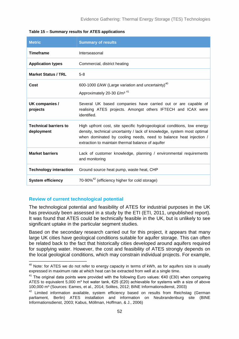
Evidence Gathering: Thermal Energy Storage (TES) Technologies
52
Table 15 – Summary results for ATES applications
Metric Summary of results
Timeframe Interseasonal
Application types Commercial, district heating
Market Status / TRL 5-8
Cost 600-1000 £/kW (Large variation and uncertainty)40
Approximately 20-30 £/m³ 41
UK companies /
projects
Several UK based companies have carried out or are capable of
realising ATES projects. Amongst others IFTECH and ICAX were
identified.
Technical barriers to
deployment
High upfront cost, site specific hydrogeological conditions, low energy
density, technical uncertainty / lack of knowledge, system most optimal
when dominated by cooling needs, need to balance heat injection /
extraction to maintain thermal balance of aquifer
Market barriers Lack of customer knowledge, planning / environmental requirements
and monitoring
Technology interaction Ground source heat pump, waste heat, CHP
System efficiency 70-90%42
(efficiency higher for cold storage)
Review of current technological potential
The technological potential and feasibility of ATES for industrial purposes in the UK has previously been assessed in a study by the ETI (ETI, 2011, unpublished report). It was found that ATES could be technically feasible in the UK, but is unlikely to see significant uptake in the particular segment studies.
Based on the secondary research carried out for this project, it appears that many large UK cities have geological conditions suitable for aquifer storage. This can often be related back to the fact that historically cities developed around aquifers required for supplying water. However, the cost and feasibility of ATES strongly depends on the local geological conditions, which may constrain individual projects. For example,
40
Note: for ATES we do not refer to energy capacity in terms of kWh, as for aquifers size is usually
expressed in maximum rate at which heat can be extracted from well at a single time. 41
The original data points were provided with the following Euro values: €40 (£30) when comparing
ATES to equivalent 5,000 m³ hot water tank, €25 (£20) achievable for systems with a size of above
100,000 m³ (Sources: Eames, et al., 2014; Solites, 2012; BINE Informationsdienst, 2003) 42
Limited information available, system efficiency based on results from Reichstag (German
parliament, Berlin) ATES installation and information on Neubrandenburg site (BINE
Informationsdienst, 2003; Kabus, Möllman, Hoffman, & J., 2006)

Evidence Gathering: Thermal Energy Storage (TES) Technologies
53
water quality and groundwater flows limit useful aquifers and ATES can only use aquifers that consist of deposits of sands and gravels and highly fractured rocks (ideally within 150m to surface) (Paksoy, Snijders, & Stiles, 2009).
The suitability of geological conditions for ATES in the UK varies, with London, the South East, Birmingham, Liverpool and East Anglia identified as areas where ATES is viable (Hendriks, Snijders, Boid, 2008). Therefore, ATES is broadly speaking a technologically feasible solution in the UK and larger uptake of ATES not strongly restricted by geological conditions. Nonetheless, the implementation and economic performance can only be assessed on individual project basis.
Additionally, ATES is most suitable where heating and cooling are required and demands are in excess of 250 kW (IF Tech, 2012). This means that ATES is a solution suitable only for large individual buildings such as apartment blocks or office buildings and community heating schemes.
Current market and product review
ATES is an established technology in other markets in continental Europe, especially in the Netherlands where it is commonly used for individual buildings (commercial and apartment blocks). By 2005 there had been 550 ATES installations in the Netherlands (Hendriks, Snijders, Boid, 2008) and this number has grown strongly since. Industry experts expressed the expectation that in the Netherlands there is the potential to reach 10,000 aquifer installations by 2020. Other countries such as Sweden, Belgium, Germany and Denmark have also had experiences with ATES applications. With the Netherlands being the most established ATES market, it provides insight into potential market development, as licensing and cooperation between aquifer users enable further growth of the technology. Until 2000, the large majority of ATES installation provided heating and cooling to individual buildings such as offices or hospitals. Since then the use for small and larger district / community heating schemes has increased and a number of utilities own and operate ATES for this purpose (Hendriks, Snijders, Boid, 2008). Generally when analysing the overall market for ATES, it is more common that buildings use aquifers to extract heat / coolth from groundwater, while systems that use wells to actively store heat / coolth are to an extent less common.
In the UK the technology remains relatively immature, with applications to-date including the National Maritime Museum, Greenwich, Westway Beacons and several projects primarily in London for commercial and apartment block buildings. As depicted in Table 15 a number of companies were identified as carrying out ATES projects. Based on the research for this report, it is estimated that there are less than 10 projects in the UK where the well system is specifically designed to store heat (and coolth) rather than just extract heat from groundwater. The number of schemes that only extract heat and coolth are likely to be slightly higher than this. Based on
these findings it can be concluded that ATES is not yet an established solution in the UK. However, the capability for the technology is increasing and there are a number of projects and market players.

Evidence Gathering: Thermal Energy Storage (TES) Technologies
54
Table 16 – Example ATES projects
Current and future system and technology costs
Currently ATES remains relatively expensive due to the upfront cost required for realising a complete integrated system. However, ATES can be relatively cost competitive for the storage size achieved (£/kWh of heat stored), especially where projects are realised at large scale. Based on the research, cost estimates are wide ranging and can be as high as £1,000 for a kW (peak) of heat extraction, when the entire system costs including components such as heat pumps are included. Unlike with other TES technologies storage capacity is usually not provided in terms of volume but the maximum rate at which heat can be extracted from the well (kW rather than kWh). To provide a comparison with other TES systems, costs of 25-40 €/m³ (water equivalent) have been reported in the literature (Eames, et al., 2014; Solites, 2012; BINE Informationsdienst, 2003). These estimates are in line or even compare favourably with other underground thermal storage technologies.
As such ATES installations can provide relatively cost effective heat storage at a similar cost point to PTES and BTES systems. However, the upfront investment required for an ATES project remains a key barrier to the widespread uptake (similar to PTES and BTES). The cost breakdown of a German pilot project in Rostock (Solites, 2012) shows that more than 80% of the total costs can be associated with the exploitation of the aquifer (i.e. drilling and building of wells) and the development of the charge and discharge systems (e.g. pipes and integrated heating system). Operation and maintenance costs are comparable to other underground based heat storage technologies and are relatively low.
Cost reduction potential – linked to the heating & cooling infrastructure
There is cost reduction potential for ATES, as there is for other interseasonal heat stores (PTES and BTES). However, these are strongly related to learnings from existing pilots and relevant system improvements. As the costs of ATES systems vary significantly depending on the individual application, a general cost reduction trajectory cannot be provided. Furthermore, a significant proportion of ATES costs are not linked to the storage itself but the heating / cooling infrastructure required.
Name / location Country Year Size
Riverlight UK 2015 3 MW cooling / 2 MW
heating
National Maritime Museum,
Greenwich
UK 2011 400 kW heating & cooling
Westway Beacons UK 2006 250 kW heating
Rostock Germany 2000 20,000 m³, 5,000 m³ (water
equivalent)
Klina Hospital Belgium 2000 Cooling capacity 1.2 MW

Evidence Gathering: Thermal Energy Storage (TES) Technologies
55
Therefore, cost reduction potentials of ATES are closely linked to those of for example ground source heat pumps and heat distribution infrastructure.
Future technological potential and development
There is significant technological potential for ATES applications in the UK, especially in larger cities such as London. Here the geological conditions are favourable for ATES and there is high demand for new office buildings and upmarket residential apartment blocks that can benefit from ATES providing both heating and cooling. It is also expected that interest from energy service providers may increase. Such providers could look to add ATES to existing and new heating and heat network solutions in order to reduce operating costs.
For district / community heating solutions, ATES could become a viable option. Throughout this research it was identified that developers of district heating are evaluating the potential for ATES. Crucially, a lack of knowledge and confidence in
the technology coupled with the geological uncertainty is proving a key barrier for an increased uptake in this sector.
Key barriers to deployment
High upfront cost requirements remain the most significant barrier to the uptake of ATES, particularly given the economic reality of developers aiming for the lowest cost option to realising building developments. Therefore, while ATES may compare favourably in terms of cost over lifetime and heat delivered, the upfront investment often creates a key hurdle. One approach to decrease the impact of this hurdle would be increasing building energy efficiency requirements for heating and cooling creating a driver for ATES solutions.
Secondly, the applicability and performance of ATES strongly depend on site-specific hydrogeological conditions. For ATES installations to be economical high well yields must be achieved. These can differ between sites and respective conditions, which creates uncertainty for developers. Such uncertainty over feasibility and financial returns, coupled with a lack of knowledge and visibility, means that uptake in the UK has been low to date.
Lastly, the specific use of groundwater creates additional planning and monitoring
requirements for project developers. In the UK this is regulated by the Environment
Agency, who require permitting procedures and monitoring to ensure thermal
balancing of groundwater sources. While not hindering the deployment of ATES,
such procedures can inevitably act as a deterrent compared to, for example tank
based storage systems, which do not require the same procedures.

Evidence Gathering: Thermal Energy Storage (TES) Technologies
56
4.6 Phase Change Material (PCM)
Phase Change Material (PCM) stores energy in the form of heat in the material’s change of phase. The most common change of phase applied is the change from solid to liquid, but using the change of phase from liquid to gas can also be feasible. The choice of material used within a PCM heat store is dependent on the required temperature for the TES.
As it changes its phase from solid to liquid, in most cases the PCM is separate from the heat transfer fluid. Thus either the PCM is encapsulated within containers and the heat transfer fluid is flowing over the container or a heat exchanger is inserted into a store full of PCM material.
There is a wide range of potential PCMs that can be used and PCM applications range from freezing to high temperature storage. To an extent PCM could compete with hot water cylinders, but at the same time it has the potential to be a complementary resource. For example through hybrid tank / PCM systems, applications where tank systems cannot physically fit, effective integration with heat pumps for time shifting electricity use or for increasing self-consumption of self-generated PV electricity. PCM applications for cooling are more advanced than for heat storage.
Materials for PCM
Both organic and inorganic compounds can be used as a PCM.
Organic compounds offer wide a range of melting points, higher safety, high latent heat and negligible super-cooling, but are costly and have low energy density, thermal conductivity and suffer from flammability.
Inorganic compounds are mainly salt hydrates or molten salts. The main advantages are lower costs, high latent heat, high specific density and a melting point range from about 5ºC to 120ºC. The disadvantages are that for long term stability these must be sealed to prevent water loss, chemical decomposition and corrosion of casing materials.
PCM’s energy density advantages are driving product development activity
The primary advantage of PCM is the higher energy density and lower volume of PCM stores compared to sensible heat stores. Therefore interest for PCM products is relatively high with several heating system and hot water cylinder manufacturers having evaluated the potential for PCM. Additionally there are smaller technology developers active in the UK and PCM heat stores in the domestic environment have been part of trial projects such as BEIS’s Advanced Heat Storage Competition run in 2012. PCM heat stores have the potential to be used with both conventional and (high temperature) renewable heat sources.

Evidence Gathering: Thermal Energy Storage (TES) Technologies
57
Table 17 – Summary results for PCM applications
Metric Summary of results
Timeframe Intra-day
Application types Domestic, commercial
Market Status / TRL 5-8
Cost Wide range and large uncertainty – reported numbers vary from
potentially as low as 40 £/kWh43
to £250 – 350 £/kWh for fully integrated
PCM stores in the residential sector.
UK companies /
projects
Sunamp, Kingspan, PCM Products, IECHP, Glen Dimplex amongst
others
Technical barriers to
deployment
Heat exchanger expense, weight of material, melting point (design for
unique melting point), heat exchanger technology requires further
development
Market barriers Combi-boiler competition in domestic market, hot water cylinders are an
established technology, lack of fully commercial products, lack of strong
supply chain, low renewable heat penetration
Technology interaction Conventional and renewable heating systems (usually requires high
temperature heat source, thus solar thermal currently not used), solar
PV
System efficiency 75-90%
Review of current technological potential
To date PCM is very much a niche market application in the UK and elsewhere, with only few products in early commercialisation phases. From a technological perspective, there is large potential for the uptake of PCM based heat stores. However, PCM is likely to be used only where there are space constraints and sensible heat stores are not realisable. Research and development efforts are focusing on integrating PCM stores into heating systems, as well as for temperature control in buildings (see IEA SHC, 2015 for further details).
There remain a number of key barriers to the wider development and uptake of PCM
stores, namely relatively high costs (although PCM is not prohibitively expensive), as well as applications where a wider temperature range is required. This is a key factor as the benefits of PCM are realisable when the temperature range of the desired application is close to the temperature where the material changes phase. Where a wider temperature range of operation is permitted sensible heat storage approaches
43
Low data point 50 €/kWh (£40) reported by IRENA, 2013. Higher end of the range reported in
industry interviews and current UK costs are likely towards the higher end of the reported scale.

Evidence Gathering: Thermal Energy Storage (TES) Technologies
58
provide a stronger financial proposition. This also explains why PCM is generally not considered for applications such as district heating.
Current market and product review
The development of PCM for storing heat is not yet at a fully commercial level. That said the industry interest for PCM solutions continues to be significant and a number of players in the UK are investing into R&D efforts for heat storage applications. Currently there are few products at an early stage of commercialisation providing an alternative to small hot water tanks in the residential sector. For example, these provide an option for increasing self-consumption of solar PV generated electricity, as the power is converted to heat and stored in the PCM tank. The product found closest to commercialisation is developed by Sunamp who have installed several hundred units as part of a Scottish Government pilot project. However, further larger heating system / hot water cylinder manufacturers as mentioned in the table above
are actively exploring the potential of PCM based heat storage.
Different thermal storage solutions using PCM are already available. For example, PCM is used in the building material industry to provide high thermal mass at a reduced weight. An example for the use of PCM in building materials are PCM plasterboards offered by multinational company Knauf. Furthermore, there are a wide range of specialised applications. For example, PCM for storing coolth from an air-conditioning system as offered by PCM Products (further discussion of these is provided within section: ‘Future technological potential and development’).
Current and future system and technology costs
A number of technology developers, as well as established heating system and hot water storage manufacturers are evaluating the case for and developing PCM products. A range of companies (presented in Table 17) have already run trials or are testing PCM products. The key focus for developers is to reduce the cost point in manufacturing to achieve price parity with hot water cylinders. Currently in the UK manufacturers are targeting a price range of approximately 250 to 350 £/kWh of heat storage. In the international literature price points as low as 50 €/kWh have been quoted for the material (IRENA, 2013).
It is likely that the cost of PCM will decrease in the future. This is anticipated to be a result of heightened R&D efforts aimed toward commercialising cost-effective products. Generally it has been found that costs are not expected to be prohibitive in the long term. Based on industry views PCM heat stores could become cost competitive (on the basis of material costs) with small hot water cylinders within the next 5 years, while for specific applications the economic case could justify investment even prior to this. However, short term cost reduction is restricted by the expense related to additional components such as heat exchangers used for PCM based thermal stores. Furthermore, quality and performance of PCM products must improve and be assured so that PCM stores can compete with small tank based systems.
Developers expect to see significant cost reductions in PCM, with prices potentially as low as 250 £/kWh of heat stored for residential applications, and becoming competitive with small and medium sized hot water cylinders over the next five years. This cost reduction will be driven by:

Evidence Gathering: Thermal Energy Storage (TES) Technologies
59
Further materials research driving down costs
Increased experience and improved manufacturing techniques driven by production volume driving down costs
Improved system design and component integration (e.g. heat exchangers)
Future technological potential and development
There are many areas of technology development and exploration of applications for PCM. The most important focus areas for technological and commercial development are highlighted below. Further information can for example be found within publications by the IEA (Annex 42/24).
Integration of PCM into small and larger hot water tanks for improved performance. Hybrid TES systems could look like a normal thermal store but include PCM element. Figure 11 shows how such hybrid store could potentially look. Throughout the industry interviews it was expressed that hot water / PCM hybrids have significant potential and are likely to emerge in the medium term future (around 2-5 years). Through hybrid solutions large thermal stores could achieve a significantly greater storage volume while at the same time reducing or maintaining the size of the storage vessel.
In future new PCMs will emerge that can provide storage for applications where water cannot be used as a storage medium. Examples include cooling applications with temperatures below 0ºC or industrial applications with temperature requirement above 100ºC.
Increasing the energy density and thermal conductivity of PCMs to make charging and discharging more efficient.
Performance and cost of heat exchangers integrated into thermal stores. One of the main challenges is the integration of the heat exchanger onto the store, while preventing corrosion from being in contact with the phase change material. To commercialise competitive PCM stores it will be key to improve heat exchanger integration and reduce component costs.
Integration into building materials – such as integration within walls and building materials improving the thermal mass of buildings and flattening heat consumption through this (enabling lower capacity heating appliances, and smoother and potentially more efficient operation of these appliances). See separate case study analysis.
Figure 11 – theoretical design
of hot water / PCM hybrid
(Source: (Castell, et al., 2009)

Evidence Gathering: Thermal Energy Storage (TES) Technologies
60
Furthermore applications include the use of PCMs for air-conditioning, passive cooling and coolth storage44.
Other potentials using latent heat include the use of ice stores for providing a constant temperature range for efficient heat pump operation (e.g. Viessmann in Germany – see case study below).
Case Study – Knauf PCM Plasterboard
An example of the integration of PCM into building materials is provided by Knauf who have developed a product called the ‘Comfortboard’. The product consists of two plasterboards which are filled with Micronal phase change material supplied by BASF.
The ‘Comfortboard’ is to have the same thermal capacity as a 100mm thick concrete wall. Using PCM to retain heat during the day and releasing it at night it reduces the energy consumption of conventional air conditioning and heating systems in a building resulting in both energy and cost savings. Based on a simple design comparable to a conventional plasterboard it can potentially be easily retrofitted as buildings are refurbished.
Case Study – Viessmann Ice Store
Viessmann, a German based manufacturer of heating and refrigeration systems, has developed an ice store system, which recovers energy from renewable sources to heat or cool a building and to heat domestic hot water. As freezing represents an exothermic process, whereby a liquid changes to solid, latent heat is released. This latent heat is retained in the ice store system.
The Viessmann ice store is used in conjunction with a heat pump. The heat pump extracts energy from water stored in the ice store. As this energy is used, the water temperature in the store will fall and in winter reach freezing point, additional energy is then obtained from the freezing of the water. Based on data provided by the company a standard 10 m³ ice store would produce a heat gain equivalent to about 100 litres of fuel oil and is capable of 10 kW of heating output when changing its phase i.e. freezing. Additionally the ice store will provide natural cooling in the summer.
The technology presented is already installed in Germany in several 100s of residential and commercial properties. In the UK, a demonstrator was installed at a ‘zero-carbon’ show home at Brooklands, Surrey.
44
There is a wide range of cooling applications for PCM such as temperature controlled distribution
(e.g. food), using PCM for increasing efficiency of air-conditioning and passive cooling, as for example
highlighted by the range of applications offered by UK based company PCM Products Ltd. For cooling
purposes PCM’s with a lower melting point are used. For example, ceiling tiles or other PCM
integrated building materials could freeze naturally overnight and release cool during the day as an
energy-free cooling source.

Evidence Gathering: Thermal Energy Storage (TES) Technologies
61
Key barriers to deployment
There are a number of crucial barriers to deployment.
Currently PCM heat storage products are available for field trials in limited domestic applications. Despite the interest in the technology, there is a lack of fully commercial products and associated learning from in-field applications.
Limited customer knowledge.
A lack of a supply chain for PCM products.
From manufacturing to installation capability, there is an overall skills shortage as PCM is primarily part of R&D efforts.
The availability of safe, reliable PCM materials with melting points suitable for most heating technologies.
PCM stores are also limited to applications where a small temperature range
between input and output is tolerable further narrowing the overall market potential.
With regards to the potential market, the relatively slow uptake of renewable heating technologies reduces opportunities for PCM products in the residential space. There would be high potential for PCM stores to provide short term storage (e.g. 3-4 hours) to allow electric heating / CHP to operate more flexibly in response to electricity system price signals. As long as the market lacks strong signals to motivate such behaviours the advantages of PCM over hot water tanks is limited, unless the customer faces space constraints in their property. Additionally, the uptake of combi boilers also proves a barrier for domestic PCM.

Evidence Gathering: Thermal Energy Storage (TES) Technologies
62
4.7 Thermochemical Heat Storage (THS)
THS has the potential to overcome some of the inherent challenges of other TES technologies, such as low energy density, high volume of stores and high temperature storage. However, THS is currently the furthest away from market commercialisation, with the bulk of the activity firmly embedded in academia and funded research.
The storage of heat is achieved through the separation of two different substances. Usually these substances are either two liquids or a solid and a vapour. They are bound by a number of physical principles or binding forces. The stronger the force binding the materials, the higher the temperature required to separate the two materials and therefore to store the heat. Generally, as the temperature increases, so does the energy density. As expressed in the IEA SHC 42/24 position paper this ranges from:
From physical sorption caused by surface forces with storage temperatures starting at 30 °C
through chemical sorption caused by covalent attraction with temperatures above 100 °C
Chemical reactions caused by ionic forces with temperatures above 200 °C.
Table 18 – Summary results for THS applications
Metric Summary of results
Timeframe Intra-day, interseasonal
Application types Commercial, industrial, district heating
Market Status / TRL 1-5
Cost Potentially very cost effective, but at current state of research very cost
intensive and not economical for commercialisation
UK companies /
projects
University research (e.g. Loughborough and Warwick University)
Technical barriers to
deployment
Unproven technology, chemical challenges, complexity, materials
design challenges
Market barriers Unproven in a market environment
Technology interaction Likely industrial heat
System efficiency Potentially very high efficiency, but in practice low efficiency due to
difficulties for extracting heat from materials.

Evidence Gathering: Thermal Energy Storage (TES) Technologies
63
Review of current technological potential
The development of THS can help support the decarbonisation of heat through a variety of potential applications, such as storage and transport of waste heat from industrial processes, interseasonal heat storage or potentially for short term heat and electricity balancing. As THS provides much higher storage capacities per mass or volume compared to sensible or latent heat storage, the role it could play is substantial.
Currently the primary knowledge around THS is based on research efforts in academia. Trials are carried out for example by the German National Aeronautics and Space Research Centre (DLR), who developed a multifunctional test environment for THS. Another demonstration project was carried out in Germany and lead by the research institute ZAE Bayern. The project explored the utilisation of waste heat from a waste incineration plant, where containers were charged up and transported to a customer using the heat. The project concluded in 2009.
Based on the current state in research it is unlikely that THS applications will be commercialised within the next 10 years. The development of real life demonstrators is an area that requires further efforts. This will be crucial for the further development of THS in order to demonstrate the technological potential and confirming the theoretical findings.
Current market and product review
As highlighted, no THS products are available in the UK. There are a number of UK and continental European universities and research institutes exploring the potential of THS. Examples of UK universities involved in THS research include amongst others, Loughborough University, Warwick University and Nottingham University.
There is significant future market potential, especially as THS is a potentially cost effective (per kWh), versatile and efficient thermal storage technology. There are a number of barriers and research gaps highlighted in the following sections that are restricting the further development.
Current and future system and technology costs
At the current level of research THS is very cost intensive and not economical for commercialisation. The high technology costs remain the primary barrier to the deployment of THS. However, as materials cost decrease and R&D efforts are able to confirm that a high system efficiency and large storage capacity are realisable, then THS could potentially be a very cost effective thermal storage solution.
The required cost reduction for THS systems is one of the key areas research is focusing on. The primary areas providing cost reduction potential are the use of new
materials and effective system integration through further trials and demonstrators. Given the very early stage development of THS, a future cost reduction potential cannot be provided with the necessary degree of certainty. Much will depend on step-changes in the state of research.

Evidence Gathering: Thermal Energy Storage (TES) Technologies
64
Future technological potential and development
THS still requires further development and there are a number of important potential application areas that are subject to the progress of current and future research. These include the:
Interseasonal heat storage from solar energy.
The storage and transport of industrial waste heat from one process / plant to a different location / industrial process or to a residential area.
Additionally, due to the high energy density of THS materials, they could play an important role for converting power to heat and therefore provide grid balancing services.
As THS is still at an early R&D stage, it can be expected that further improvements and step changes are possible. For example, work carried out under the IEA SHC
Annex 42/24 (Sibbitt & McClenahan, 2015) highlights that first laboratory tests of systems using already existing materials (e.g. zeolites, salt hydrates and composite materials) are being undertaken in 2015 and 2016. Field tests with such laboratory tested systems would then likely follow within the next five to ten years.
Key barriers to deployment
The most prohibitive barrier for the deployment of THS is the upfront cost and investment required for technology and product development. Costs remain very uncertain; more certainty on potential cost-effectiveness will require time and further research.
The technical barriers for the further development of THS can be summarised as:
Materials research
Component development and design
System design and integration
Basic research is still required to fully understand the physical and chemical characteristics of the different potential materials. Specific issues such as the development of novel sorption materials, how to choose different chemical materials and understand how they react, as well as the way components operate in the vacuum conditions of a thermochemical heat store are being addressed by research.
Importantly there remain significant challenges and gaps in knowledge around cycling behaviour, toxicity and safety, corrosiveness, energy storage density of various materials, reaction temperature and rate / speed of reaction. Due to the variety of potential THS technologies, a detailed analysis would be outside the scope of this study. Gaps in knowledge remain and would require the further exploration of THS.

Evidence Gathering: Thermal Energy Storage (TES) Technologies
65
5 Market review and future development
5.1 Current UK market overview
Overall, there are two primary TES technologies that have experience of widespread uptake in the UK:
Electric storage heaters (approximately 1.8 million homes in the UK use electric heating system, of which the large majority will be electric storage heaters).45
Tank based systems:
o Residential systems (around 11 million systems in homes; approximately 400,000 sold per year)
o Larger systems (>500 litres), selling low thousands of units each year for large residential or commercial applications. There are tens of systems in the district heating segment, where tanks are usually of a size between low hundreds to thousands of m³.
Other systems have seen much more modest uptake. Based on our research there were projects identified for each underground TES technology. The number here ranges from a few single projects to low tens of installations being carried out. There is a high degree of uncertainty with regards to PTES, BTES and ATES projects, because there has been very little discussion in the literature and the projects realised are very much niche applications. Across these three technologies, the key barrier explaining the small current market is the high upfront cost and related cost sensitivity shown by building / project developers. The low uptake of PTES and BTES can also be broadly linked to the low uptake of large solar thermal in the UK – especially PTES, commonly used for the interseasonal storage of solar heat.
With regards to emerging TES technologies – PCM and THS – the commercially motivated uptake of systems remains very low. The primary development of PCM has been as part of European funded research projects, as well as BEIS’s Advanced Heat Storage Competition. For the latter a number of UK based research organisations and commercial developers investigated different applications and the technological potential of PCMs. Additionally, Scotland based developer Sunamp has installed approximately 800 units of different specification as part of the Scottish Government’s ‘Low Carbon Infrastructure Transition Programme’.
45
There is a lack of robust annual sales data specifically analysing electric storage heaters and
electric heating in general. The data provided (approx. 1.8 million) is based on figures provided
through industry interviews and Delta-ee analysis of various housing stock surveys such as English
and Scottish Housing Surveys, DECC Housing Energy Fact File and Department for Communities
and Local Government.

Evidence Gathering: Thermal Energy Storage (TES) Technologies
66
For THS there is currently no market as such, as the development of the technology is firmly embedded within academic research at the current point in time. There are also very few demonstration projects proving the technology’s capabilities, thus justifying a TRL of 1-5.
Table 19 – Current market status of TES in the UK
Application type Intra-day storage Interseasonal storage
District Heating Increasing integration of TTES in new
DH installations and limited retrofit
efforts.
No interseasonal applications within
UK district heating schemes.
Non-domestic Stable and established market for
water based TTES (10,000s of units).
Limited applications with low 10s of
various underground TES for
interseasonal heat storage.
Domestic Stable and established market for
water based TTES (100,000s of units
p.a.).
Pilots and early commercial products
using PCM.
Very few (low 10s) applications of
small scale solar / GSHP coupled
borehole installations.
5.2 Factors affecting future adoption of TES
From an isolated technology perspective there should be very little constraint for bringing the majority of the technologies shown in this report to market. Aside from THS, which is primarily developed within the academic and research community, the concepts of the different TES types have been proven in trial projects and some commercialised applications across the UK or at least in other northern European countries.
However, to drive the UK TES market further two factors need to be present: a stronger understanding of and confidence in the various technologies beyond hot water tanks and storage heaters; and price signals that enable TES to deliver value to customers.
The crucial cap is economics and upfront costs of different TES technologies – there are few price signals to drive the market (e.g. dynamic electricity pricing). TES would benefit if these signals become more widespread and stronger. This may occur where more intermittent electricity generation is seen in the market.
There are price signals present today for larger-scale generation – for example large CHP feeding district heating networks has some time of use value to the electricity produced. However, they are largely absent at the residential scale – except for Economy 7 tariffs and some emerging business models around flexible demand.
Lastly it can be expected that the number of district heating schemes will grow further (if decarbonisation of heat through electrification scenarios are

Evidence Gathering: Thermal Energy Storage (TES) Technologies
67
assumed) and the majority of new schemes will most likely use water based TTES.
Large scale solar thermal plants drive the integration and deployment of interseasonal, underground TES, as seen in countries such as Denmark and Germany. Based on the limited uptake of solar heating in UK district heating schemes there may potentially be limited demand for interseasonal heat storage using PTES or BTES in the UK over the coming years.
5.3 Future Scenarios for TES market development
This section will outline the rationale for two possible TES deployment scenarios with one providing a potential ‘business as usual’ development where TES in the UK would continue on an existing path. Deviating from this, an alternative scenario for
the decarbonisation of heat and use of TES for electricity time shifting is presented.
Scenario 1 – Business as usual
In summary, the business as usual scenario assumes a more or less stable market for TTES in the UK for the residential and small commercial sector, while there may be slight growth in the uptake of large hot water tanks for new district heating schemes. However, there would be very little drive for the uptake of different interseasonal TES technologies for all types of applications specified. Research and development efforts for PCM and THS will continue and some early PCM products could become commercialised within two to five years in niche applications.
Electricity price signals
Under scenario 1 there would be some price signals for intra-day thermal storage. This would impact the value that could be extracted from district heating schemes with CHP (electricity production) or heat pumps (electricity consumption), as well as large commercial demands also using these technologies.
At residential level the only price signals are currently Economy 7 tariffs and under the business as usual scenario no introduction of significantly stronger and more dynamic electricity pricing would be introduced.
This would primarily be based on the lack of strong price signals from the system operator, network operators or energy suppliers. A small existing number of aggregators and demand response players would offer the potential for exploiting the small existing signals reducing complexity and ‘worry’ factor for end users.
Renewable heat drivers
Instead of a significant step change in the deployment of renewable heating
technologies, the business as usual scenario assumes a slowly growing market. In the residential sector, there may be modest increases with regards to heat pump sales, at best a stagnation of solar thermal deployment and relatively steady sales of biomass boilers.
In the commercial and district heating segment, natural gas fired CHP will continue to be the dominating technology. There would likely be an increasing interest and trials for other technologies that could improve energy efficiency of buildings for

Evidence Gathering: Thermal Energy Storage (TES) Technologies
68
heating and cooling, such as ground source heat pumps. For district heating hot water based tank storage is likely to be deployed with most new applications. Renewable heating, such as industrial heat pumps and large scale solar thermal are likely to see little or no drive under this scenario.
Deployment until 2025
Table 20 – Potential uptake of different TES applications under ‘business as usual’ scenario
Application
type
Intra-day storage Interseasonal storage
District
Heating
Uptake of TTES in most new installations and some
retrofit efforts.
Unlikely to see uptake of
any other TES for DH apart
from few possible trials.
Non-
domestic
Stable market for TTES.
Potential emergence of suitable PCM products likely as
part of trial projects.
Slowly increasing, but low
uptake for large individual
buildings (e.g. office blocks).
Domestic Stable market (annual sales) for hot water based TTES
Commercialisation and limited uptake of PCM products
replacing or being integrated in hot water cylinders.
Limited applications of small
scale solar / GSHP coupled
borehole installations.
Scenario 2 – Strong drive to decarbonise heat (focus on electrification of heat and new market frameworks for flexibility)
Scenario 2 assumes a more positive outlook for TES in the UK based on strong drivers from the decarbonisation of heat, primarily through its electrification and favourable frameworks for providing flexibility to the network. In the residential and small commercial sector sales of hot water cylinders would increase and new products such as PCM would emerge. Additionally interseasonal TES would receive a stronger push with trial projects looking to exploit the potentials for solar thermal integration as efforts to decarbonise heat further develop.
Electricity price signals
This growth scenario assumes the emergence of strong time-of-use prices for end-customers. Different types of customers would be rewarded for shifting demand away from peak electricity demand periods – or for generating during times of peak electricity demand. TES together with intelligent controls and effective system integration enable production of heat from electricity, or CHP, to exploit these price signals.
The underlying rationale for improved electricity price signals that can be exploited with TES would be high levels of renewable energy generation. Upstream price signals, such as balancing services or network operator incentives emerge and a growing number of aggregators and demand response players monetise flexibility from distributed assets.

Evidence Gathering: Thermal Energy Storage (TES) Technologies
69
Renewable heat drivers
Scenario 2 requires strong drivers to reduce fossil fuel consumption, and reduce dependence on oil and gas for meeting heat requirements. The widespread uptake of renewable heating technologies, and especially the electrification of heat using heat pumps would provide a very favourable outlook for the deployment of TES. The ability to decouple production from consumption of heat through thermal storage would make the integration of electric heating into existing electricity networks easier.
Stricter building regulations requiring more energy efficient technologies to be used in new builds and existing buildings would increase the uptake of renewable heating technologies. Furthermore, it would also encourage the installation of underground TES such as BTES or ATES for improving performance of heating and cooling in large buildings.
Lastly this potential scenario outlines the possibly increasing uptake of large hot water storage for community and district heating schemes, as such schemes increase in popularity and receive continuous support as part of decarbonisation strategies (assumption for growth scenario). This was also echoed amongst the industry expressing plans for increasing district heating installations in the UK. It will be likely that in order to improve system performance the majority of these new schemes will be paired with TTES. Additionally it will become the norm to retrofit hot water TTES to existing CHP fed district heating schemes. There may also be more interest around using solar input for district heating in the UK acting as a strong driver for interseasonal TES.
Deployment until 2025
Table 21 – Potential uptake of different TES applications under ‘growth’ scenario
Application
type Intra-day storage Interseasonal storage
District
Heating
Strong growth of DH using heat pumps
and/or CHP; TTES in all new installations
and majority of DH retrofitting TTES.
Potential for limited trials integrating PCM
with hot water stores (Hybrid tank / PCM).
Trials and early adoption of
underground TES technologies for
district heating applications with
solar thermal.
Non-
domestic
Growing market for TTES based on
renewable heating uptake and CHP.
Development of more novel TTES
applications using other materials than
water.
Potential emergence of suitable PCM
products likely as part of trial projects.
Growing uptake of ATES and
BTES for individual commercial
buildings as technologies such as
GSHP and solar achieve greater
uptake.
Emergence and improvement of
early pilots for THS applications in
the industrial sector.
Domestic Growing market for TTES based on electric
heating uptake (and possibly micro-CHP)
and electricity price signals for flexibility.
Uptake of PCM products for time shifting
renewable heating and mitigating space
constraints in properties.
Different types of BTES becoming
more established based on
coupling with renewable heating
technologies.

Evidence Gathering: Thermal Energy Storage (TES) Technologies
70
5.4 Key barriers
There are a number of barriers present today, which must be overcome if we are to see significant uptake of TES technologies in the UK beyond the established tank based hot water storage. Most obvious and echoed throughout the research is the issue around upfront cost of systems. However, there are further barriers such as the integration of TES installations into existing heating systems, relatively low uptake of renewable heating technologies, absence of strong drivers for time shifting of electricity consumption, awareness and knowledge, as well as the remaining gaps in research and project demonstration.
This section highlights some of the overarching barriers identified throughout the detailed technology analysis and discusses how these barriers may be reduced in
the future.
Upfront cost of TES
As discussed throughout the technology analysis, upfront cost remains a major barrier to the wider deployment (or to be strictly accurate high upfront cost without strong enough revenue opportunities). While not prohibitive in the residential sector for hot water cylinders (requirement for different heating system types), it is the primary barrier to the uptake of large scale storage for commercial, industrial and district heating users. Throughout the research it was expressed that especially building developers are reluctant to go for a higher upfront cost option, despite potential long term efficiency improvements. For underground TES technologies upfront investment is significant ranging from £100,000 to multi million pound investment required to realise a project.
For the commercialisation of PCM and thermochemical TES costs are also a crucial barrier. Most PCM products would be too expensive for replacing hot water tank based systems at the current point in time. In terms of PCM and hot water cylinders competing for overall TES market share, there may be the potential of PCM stores replacing some tank systems. Although it is more likely that PCM products would complement the TTES market, either through hybrid applications or by using PCM based stores for different applications (e.g. space constraints or short-duration smoothing of heat pump production). The cost required for research and development of new PCM and THS technologies could also prove prohibitive to the advancement of the technologies.
Electricity price signals
Storing a kWh of heat can be several times cheaper than storing a kWh of electricity
in batteries, so using TES to absorb electricity and output heat may become a significant driver of thermal energy storage. For an improved value proposition for different TES technologies, time-of-use tariffs and price signals for time shifting electricity (intra-day) would likely be a driver for the uptake of TES.
The use of thermal storage for electricity grid balancing is technically feasible today (using tank, PCM thermal storage and electric storage heaters). With the only price signals at residential level currently being Economy 7 tariffs, the signals given to

Evidence Gathering: Thermal Energy Storage (TES) Technologies
71
customers are neither strong nor dynamic enough to extract significant value from thermal storage. Additional value could be extracted from district heating schemes with CHP (electricity production) or heat pumps (electricity consumption), as well as large commercial demands also using these technologies.
Uptake of renewable heating technologies
The uptake of renewable heating technologies in the residential, commercial and district heating sector remains limited compared to the overall market of conventional heating systems such as gas boilers. TES can be an enabler for these technologies – and so the widespread deployment of TES is also dependent on their increasing uptake.
Intelligent control systems for renewable heating technologies may reduce the opportunity for TES as they help to match heat generation to heat demand, and provide some flexibility for timing of heat production. But overall intelligent controls
are driving TES applications, as intelligently controlled TES will likely help maximise flexibility and matching of heat generation and heat demand.
Large tanks, boreholes, pits and aquifers have all been piloted for interseasonal storage of solar thermal heat and passive solar. Thus, the uptake of solar thermal technologies is crucial to enable growth of interseasonal storage. The use of ‘ground source air conditioning’ and interseasonal storage of solar heat may also grow significantly if future building regulations were to require close to zero-carbon buildings.
System integration
The integration of TES into existing heating systems and for new installations can prove difficult on a number of levels – such as space constraints, installation challenges and control elements. System integration is an issue for both small residential systems and larger scale storage projects.
Heating system integration and installation
For retrofit installations of domestic, commercial and district heating applications there is an inherent difficulty to integrate TES with an existing system without any existing storage capability. Often this adds additional installation requirements that may add complexity and cost. Secondly, and often more significant is the integration of an intelligent control system for optimising the operation of the system with a thermal store.
Space constraints
Specifically for small water cylinders in the residential space and for small commercial buildings, the growing penetration of combination boilers could prove a
barrier for thermal storage. With many new residential houses using combi boilers, no space for thermal storage is incorporated into the design of the buildings. Therefore, this may potentially rule out the future potential for these houses to be retrofitted with renewable heating technologies requiring heat storage.
As space comes as a premium in most UK cities, the integration of thermal stores into energy centres of large buildings is often a key constraint for TES. For district heating applications that were built without significant thermal storage, finding an

Evidence Gathering: Thermal Energy Storage (TES) Technologies
72
adequate site for a large TES can prove to be a major barrier. There are examples of innovative underground tank solutions, that once installed would allow for normal use of the land above. Additionally, there may be scope for evaluating the potential of small decentralised thermal stores located at the site of end-users connected to the district heating scheme. Either solution could potentially help overcome space constraints.
Knowledge and awareness
Awareness about TES technologies, other than hot water cylinders and larger water based TTES, is very low among end-users and building developers. As such, there is little uptake outside the traditional ‘hot water storage’ market, which has been steady but not increasing in the past.
Lack of awareness and aversion to anything ‘new and different’ was repeatedly raised in interviews with industry, especially for interseasonal applications for
commercial buildings, such as BTES or ATES, which can help increase energy efficiency and decrease running costs. This applies to the building industry and the heating industry supply chain.
Research gaps and project demonstration
As the majority of TES products are yet some way off widespread commercialisation in the UK and elsewhere, current knowledge gaps and the lack of replicable demonstrators in the UK create a barrier to the further commercialisation of interseasonal storage, PCM and THS solutions. Advanced demonstrator projects would enable the testing of different application models and create knowledge and confidence with regards to technological performance for UK developers and end-customers. Specific gaps are highlighted in the gap analysis provided in chapter 6.

Evidence Gathering: Thermal Energy Storage (TES) Technologies
73
6 Discussion of key gaps
6.1 Introducing key gaps
Throughout the course of this project, a number of gaps in the available knowledge and level of research were identified. In fact due to the relative immaturity of several TES technologies and a lack of widespread UK based applications the number of gaps was especially high. Five key themes were identified and these can broadly be summarised as follows:
Commercialisation challenges
Uncertainty around future cost reduction
Uncertainty around performance of TES technologies
Lack of interseasonal heat storage knowledge in the UK
Uncertainty around direct carbon savings and wider electricity system benefits.
This section will introduce each of these themes and highlight specific market, technology and research challenges encountered. There is the potential and need to address many of these gaps through further research in order to help overcome them.
6.2 Commercialisation challenges
One of the central challenges expressed throughout the analysis for this report was that aside from TTES using hot water and electric storage heaters, no other thermal energy storage technologies are fully commercialised in the UK. In order to unlock the full potential of TES for supporting the decarbonisation of heat, providing electricity balancing services and improving the efficiency of other interacting technologies, a range of TES applications are needed to come to market.

Evidence Gathering: Thermal Energy Storage (TES) Technologies
74
Table 22 – Review of key commercialisation gaps
Key Gaps Discussion of gap
Electricity price signals Lack of dynamic electricity tariffs, and other sources of value for time-shifting demand affecting confidence of both end-users and developers.
Scaling production and size of projects
Uncertainty over the scalability of products and implementation of large projects remains. Many applications have been proven at a smaller scale / as a demonstrator, but actual performance and cost efficiency is likely to be proven only by carrying out larger volume / a larger number of projects.
Physical constraints Better understanding of physical space constraints for TES applications in the UK and how to overcome them.
PCM PCMs are increasingly close to being commercialised, with some products already launched. There remains a gap around the development of PCMs with the right temperature input for heat pumps.
Secondly the development and commercialisation of hybrid TTES / PCM products remains an area open for further research.
Development of clear standards for different types of TES
Throughout the research it was expressed that there is a need for clear standards of performance for different types of TES, especially as new products using PCM are developed. The review of standards was not in the scope of this report so commentary on this subject was excluded.
Similarly some concerns were raised that there is uncertainty around standards and guidelines for integrating thermal storage with different renewable heating technologies.

Evidence Gathering: Thermal Energy Storage (TES) Technologies
75
6.3 Uncertainty around future cost reduction
Throughout this project, the future cost reduction potential for different TES technologies has been considered and by seeking views of manufacturers and researchers in the area, an indicative cost trajectory was provided for each technology. Given the relative early stage development of several types of TES, in order to increase the level of confidence in future cost scenarios, it would be necessary to carry out additional research focused specifically on this topic.
Table 23 – Review of key cost reduction uncertainties
Key Gaps Discussion of gap
Future cost trajectories for immature technologies
Several technologies are between 5 to 10 years away from mass commercialisation in the UK (e.g. PTES, PCM, THS). Therefore accurate cost trajectories are very difficult to forecast, as unforeseen step change developments may occur, significantly reducing costs.
Proven methods and supplementary components
Technologies such as TTES, PTES, BTES are unlikely to see significant cost reductions, because much of the supplementary technology / installations techniques are well proven. Examples include:
Drilling of boreholes
Excavating, lining and insulating for PTES
Manufacturing and installing water tanks
Further research would be needed to accurately predict cost reductions in these areas, because improvements are not exclusively related to the development and uptake of TES

Evidence Gathering: Thermal Energy Storage (TES) Technologies
76
6.4 Uncertainty around performance of TES technologies
Performance of TES has been discussed for each specific technology and application. Small and medium size water based TTES aside, performance parameters are largely based on pilot projects. To confirm the performance reported for pilot projects carried out elsewhere in Europe, it is important to develop and monitor a greater number of demonstrator projects / installations in the UK. Many of the projects abroad have also not been in operation long enough to measure their long term performance parameters and impacts of individual TES systems. Some technology specific gaps are outlined below.
Table 24 – Review of key performance gaps
Key Gaps Discussion of gap
Understanding efficiency and heat losses
To enable robust performance and subsequently sound financial evaluations, the understanding of losses from interseasonal heat storage for individual buildings should be explored further.
Understanding thermodynamic performance
There remain gaps in knowledge around the real life thermodynamic performance (e.g. stratification of heat) especially for TES concepts that have so far only been proven in theory.
Sizing of TES The correct sizing of TES in accordance to the size and performance of the adjacent heat source (e.g. heat pump) over a wide range of operating conditions may require additional testing and would benefit from an independent certification process / guidelines.
PCM Several key areas for R&D in PCM can be identified. Amongst a range of issues, the development and testing of PCM with different melting points, as well as high temperature PCM stand out. Additionally proving the longevity of a number of phase change materials is required.
Hydrogeological conditions
There is uncertainty over the wider hydrogeological conditions across the UK. A mapping exercise outlining generally suitable areas for BTES and ATES would potentially be worth exploring for supporting the deployment of TES (e.g. industry interview highlighted that a mapping exercise was carried out in the Netherlands).
Materials research There remains uncertainty with regards to performance of different materials used for TES:
Uncertainty over long term quality and performance of lining & insulation for PTES. This can only be measured through long term measuring and monitoring (e.g. currently carried out by the Danish Technology Institute).
Understanding and highlighting the difference in various phase change materials available.
Understanding characteristics of different thermochemical materials for TES.
Evidence Gathering: Thermal Energy Storage (TES) Technologies
77
6.5 Lack of interseasonal heat storage knowledge in the UK
For interseasonal heat storage, developments in the UK are far behind those advancements made in other northern and central European countries.
This creates uncertainty and as such there are a number of specific issues that should be addressed in a domestic context. Providing additional research and clarity around these would provide better confidence in novel TES technologies and support the economic evaluation of potential projects.
Table 25 – Review of key interseasonal storage gaps
Key Gaps Discussion of gap
Utilisation of large scale and interseasonal TES
There is a lack of experience in utilising large scale, interseasonal PTES / BTES / ATES for commercial and district heating applications in the UK. Therefore there remains significant uncertainty with regards to system suitability and how they would perform in the UK, which could potentially be addressed through pilot schemes.
6.6 Uncertainty around carbon savings
Interest in TES is high because of the role it could play in transitions to a low- and zero-carbon energy system (see chapter 3). TES may have an important role as an enabler of low-carbon technologies, particularly renewable heat, electricity and CHP. However, at present, the existence of thermal storage capacity can increase carbon emissions. This is because all storage systems have losses, and these losses are effectively wasted fuel or wasted electricity (both still predominantly fossil-derived).46
Understanding the carbon impacts of TES is therefore not at all simple. At a whole-system level it would require complex system-modelling to justify any statements about a unit of TES (a kWh or kW) equating to a quantity of saved carbon47. The carbon content of the TES itself is in all cases relatively low, as the storage material (whether water, rock or advanced PCMs or thermochemical materials) does not require excessive energy to produce and the containers do not use rare materials or energy intensive production methods.
46
Note that this is equally true for any form of energy storage (i.e. also electricity storage in any form). 47
Examples of such complex system modelling are for example provided by Imperial College
(Imperial College, 2015). See: http://wwwf.imperial.ac.uk/business-
school/research/management/management-research/projects-and-centres/energy-storage-for-low-
carbon-grids/

Evidence Gathering: Thermal Energy Storage (TES) Technologies
78
Table 26 - Review of key gaps relating to carbon savings from TES
Key Gaps Discussion of gap
Quantifying savings
from specific TES
applications
Where TES enables solar thermal or other renewable heat to be used savings are relatively straightforward, except where borehole or aquifer storage is used (due to high degree of uncertainty around how much energy injected into the ground is later extracted).
Savings from electricity time-shifting (i.e. heat pump operating time changes, or immersion dumping during electricity oversupply) are very difficult to quantify, due to difficulties with baselines and the need to model what would be used to provide electricity grid flexibility if TES was not available in each situation (simple carbon factors are not valid for peak or trough electricity).
Savings from using TES to provide ancillary services are notoriously hard to quantify, because of difficulties with baseline comparisons.
Savings from steadier operation of CHP or industrial processes are easier to model, at least when they relate to higher fuel efficiency per kWh of heat or electrical output.
Valuing savings
from ‘renewable
cooling’
Using underground interseasonal stores to balance the need for cooling and heating in a building can provide a very low-carbon building comfort solution. But there is some conceptual uncertainty about how savings should be calculated.
In order to maintain a steady inter-annual borehole or aquifer temperature the heating (or, less commonly, cooling) circuits of underground TES systems may need to be operated more than is strictly required for inhabitant comfort.
TES losses As mentioned above, losses from borehole and aquifer storage are very uncertain. When the input energy is ‘free’ (i.e. summer office heat that needs to be extracted anyway) this may not matter to the business case, but it does make calculating carbon savings very problematic.
TES applications to
support electricity
system challenges
There is a lack of evidence around how TES applications can be used to provide value to the electricity system through time-shifting electric heating or combined heat and power.

Evidence Gathering: Thermal Energy Storage (TES) Technologies
79

Evidence Gathering: Thermal Energy Storage (TES) Technologies
80
Sources
Bergan, P. G., & Greiner, C. J. (2014). A New Type of Large Scale Thermal Energy Storage. Energy
Procedia, 58, 152–159.
BINE Informationsdienst. (2003). Aquiferspeicher fur das Reichstagsgebäude. Retrieved from
http://www.bine.info/fileadmin/content/Publikationen/Projekt-Infos/2003/Projekt-Info_13-
2003/projekt1303internetx.pdf
Castell, A., Solé, C., Medrano, M., & Nogués, M. (2009). Comparison of Stratification in a Water Tank
and a PCM-Water Tank. Journal of Solar Energy Engineering, 131(2).
Committee on Climate Change. (2015). Sectoral scenarios for the Fifth Carbon Budget - Technical
Report. London: Committee on Climate Change.
BEIS. (2013, July). Summary evidence on District Heating Networks in the UK. London.
BEIS. (2013, May 8). The winners of the Advanced Heat Storage scheme. Retrieved from Department
of Energy & Climate Change:
https://www.gov.uk/government/uploads/system/uploads/attachment_data/file/197168/T
he_winners_of_the_Advanced_Heat_Storage_scheme.pdf
Eames, P., Loveday, D., Haines, V., & Romanos, P. (2014). The Future Role of Thermal Energy Storage
in the UK Energy System: An assessment of the technical feasibility and factors influencing
adoption. London: UKERC.
Energy Research Centre of the Netherlands (ECN). (2013). Compact thermal energy storage report.
Science Applications International Corporation Canada.
Energy Technologies Institute. (2011). Energy Technologies Institute (ETI) Heat Capture and Storage
Study. London: ETI.
European Commission. (2013, December 10). Hoirzon 2020 Work Programme 2014-2015, 19.
General Annexes . Brussels.
Gao, L., Zhao, J., & Tang, Z. (2015). A Review on Borehole Seasonal Solar Thermal Energy Storage.
Energy Procedia, Volume 70, 209–218.
Hendriks, M., Snijders, A., & Boid, N. (2008). Underground Thermal Energy Storage for Efficient
Heating and Cooling of Buildings. Retrieved from IFTech:
http://www.iftech.co.uk/files/Article3_IFTech31March08-ADK91v.pdf
IEA SHC. (2015). Compact Thermal Energy Storage IEA SHC Position Paper. IEA SHC.
IF Tech. (2012). An Introduction to Aquifer Thermal Energy Storage (ATES). UTES Rehau Workshop.
IRENA. (2013). Thermal Energy Storage - Technology Brief. Masdar City: IRENA.

Evidence Gathering: Thermal Energy Storage (TES) Technologies
81
ITW Stuttgart. (2008). Seasonal Thermal Energy Storage: A Challenging Application for
Geosynthetics. Retrieved from ITW Stuttgart: http://www.itw.uni-
stuttgart.de/dokumente/Publikationen/publikationen_08-08.pdf
Jensen, M. V. (2014). Seasonal pit heat storages - Guidelines for materials & constuction (IEA-SHC
INFO SHEET 45.B.3.2). IEA SHC.
Jensen, M. V., & From, N. (2013). Two Approaches of Seasonal Heat Storing: Pit Heat Storage and
Borehole Thermal Energy Storage. Solar District Heating Conference. Malmo.
Jensen, M. V., From, N., & Sørensen, P. A. (2015). Larhe Scale Solar Thermal Plants with Long Term
Heat Storages. Examples from Marstal, Braedstrup and Dronninglund, DK. Solar District
Heating Conference. Toulouse.
Kabus, F., Möllman, G., Hoffman, F., & J., B. (2006). The 10th International Conference on thermal
energy storage . Retrieved from
https://intraweb.stockton.edu/eyos/energy_studies/content/docs/FINAL_PRESENTATIONS/
13A-1.pdf
Martin, M., & Thornley, P. (2013). The potential for thermal storage to reduce the overall carbon
emissions from district heating systems. Manchester: Tyndall Centre.
Martin-Du Pan, O. (2015). Operational Performance Assessment of Decentralised Energy and District
Heating Systems. Loughborough: Loughborough University.
Miedaner, O., & Sørensen, P. A. (2015, May 21). Borehole thermal energy storage systems and large
scale sensible hot water storages in Germany and Denmark. IEA ECES Greenstock 2015.
Beijing.
Paksoy, H., Snijders, A., & Stiles, L. (2009). Review of ATES Systems for Heating and Cooling Buildings.
Retrieved from Stockton University:
https://intraweb.stockton.edu/eyos/energy_studies/content/docs/effstock09/Session_6_3_
ATES_Applications/53.pdf
Pauschinger, T. (2012). Solar District Heating with Seasonal Thermal Energy Storage in Germany.
Retrieved from Euroheat:
http://www.euroheat.org/Admin/Public/DWSDownload.aspx?File=%2FFiles%2FFiler%2FPres
entations%2F20120618-22_EUSEW%2F120619_EUSEW_5+-
+Pauschinger+Solites_SDHGermany_120618.pdf
Schnürer, H., Sasse, C., & Fisch, M. N. (2006). Thermal Energy Storage in Office Buildings Foundations
. Retrieved from Stockton University:
https://intraweb.stockton.edu/eyos/energy_studies/content/docs/FINAL_PAPERS/11A-
4.pdf
Sibbitt, B., & McClenahan, D. (2015). Seasonal Borehole Thermal Energy Storage – Guidelines for
materials & construction (IEA-SHC TECH SHEET 45.B.3.1). IES SHC.
Sibbitt, B., McClenahan, D., Djebbar, R., Thornton, J., Wong, B., Carriere, J., & Kokko, J. (2012). The
Performance of a High Solar Fraction Seasonal Storage District Heating System. Energy
Procedia, 30, 856–865.

Evidence Gathering: Thermal Energy Storage (TES) Technologies
82
Solites. (2012). Technisch-wirtschaftliche Analyse und Weiterentwicklung der solaren Langzeit-
Wärmespeicherung. Stuttgart: Solites.
Sørensen, P. A. (2015). Large Scale Solar Thermal Plants with Long Term Storages: Examples from
Marstal, Braedstrup and Dronninglund, DK. SDH Conference Toulouse. Plan Energi.
Sunstore 4. (2010). Marstal Sunstore 4 - Project Evaluation Document. Marstal: Marstal Fjernvarme.
Ullrich, S. (2015). Versorger Trend: Nahwaermenetze. Erneuerbare Energien, 54-57.

Evidence Gathering: Thermal Energy Storage (TES) Technologies
83
List of research conversations
E.ON
Gledhill
Engie (Cofely)
Dimplex
Hot Water Association
Plan Energi
Kingspan Renewables
ICAX
VCharge
IFTech
Sunamp Ltd.
Ecovat
PCM Products
ETI
Caplin Homes / Earth Energy Bank
Isentropic
Northman Group / Jaspi UK
Community Energy Solutions
CTC Renewables / Enertec
Loughborough University
Warwick University
BEIS (Advanced Heat Storage Competition)

Evidence Gathering: Thermal Energy Storage (TES) Technologies
84
Glossary
ATES Aquifer Thermal Energy Storage
BTES Borehole Thermal Energy Storage
CHP Combined Heat Power
BEIS Department for Business, Energy and Industrial Strategy
DH District Heating
DLR German National Aeronautics and Space Research Centre
ErP Energy related Products
kW Kilowatt
kWh Kilowatt hour
IEA SHC International Energy Agency Solar Heating and Cooling Programme
IRENA International Renewable Energy Agency
PCM Phase Change Material
PTES Pit Thermal Energy Storage
PV Photovoltaics
R&D Research & Development
TES Thermal Energy Storage
THS Thermochemical Heat Storage
TRL Technology Readiness Level
TTES Tank Thermal Energy Storage
UK United Kingdom
UKERC UK Energy Research Centre

Evidence Gathering: Thermal Energy Storage (TES) Technologies
85
© Crown copyright 2016
Department for Business, Energy and Industrial Strategy
3 Whitehall Place
London SW1A 2AW
www.gov.uk/beis