design aspects of a 26500-rpm, 2-kw high- speed …ecai.ro/arhiva/ecai-2016...
TRANSCRIPT

ECAI 2016 - International Conference – 8th Edition Electronics, Computers and Artificial Intelligence
30 June -02 July, 2016, Ploiesti, ROMÂNIA
Design Aspects of a 26500-rpm, 2-kW High-Speed Permanent Magnet Synchronous Generator for Turbomachinery Systems
Sami Arslan Electrical & Electronics Eng. Dept.
Eng. Faculty-Gazi University Ankara Turkey
Ires Iskender Electrical & Electronics Eng. Dept.
Eng. Faculty-Gazi University Ankara Turkey
Abstract- Recent developments of power electronics technology, coupling technology, low-loss iron core materials and highly efficient permanent magnets have made it possible to realize a small size, high-speed and high performance electrical drive system. In this paper we focused on designing of highly efficient high-speed permanent magnet synchronous generator of in-runner, surface mounted, 4 poles, 2 kW and 26500 rpm for turbomachinery systems especially for turbocharger which will be used in our micro-CHP project. The criteria of selecting materials, suitable machine type, rotor structures and initial boundary conditions are explained. Electric and magnetic design of the High Speed Permanent Magnet Synchronous Generator (HSPMSG) is conducted analytically in Ansys RMxprt with parametric solutions and analyzed in Ansys Maxwell 2D&3D by finite element method (FEM) with magnetostatic and transient solutions to make the fine adjustment of the detailed machine shape and to seek the best design parameter set. The retaining sleeve is also used to provide mechanical integrity and continuity of the HSPMSG and to understand whether it is suitable for working conditions at related speeds or not. This work will also be partake of development of the related designed high speed generator.
Keywords- High speed generator; generator design; permanent magnet; turbine engines; turbomachinery systems
I. INTRODUCTION
Permanent magnet machines have become increasingly popular in the last two decades. Recently it also becomes possible to realize a small size, high-speed and high performance electrical drive system due to the following reasons, i-improvements and cost reduction in power electronics circuits, ii-high energy permanent magnets and low iron loss electrical steels, iii-reliability improvements in high rotational speed machines like turbomachinery systems as turbochargers, iv-improvements in bearings with reliable lubrication and wide spread use of magnetic bearings, v-computer analysis and simulation technologies in design processes, and vi-bearingless and sensorless operation [1].
High speed shaft means to get rid of the power transmission system parts like gear-boxes and belt-
pulleys so that the reduction of the dimensions of the electric machines.
Reduced size leads to light and portable electric machines and direct coupling of the machines leads to more efficient systems. Also the superiorities of the high speed electric machines against the low speed ones are; high efficiency, reduced size, low weight, compactness, easy maintenance and easy cooling [2].
This type drive is expected for various kinds of applications such as aerospace, co-generation systems, electrical vehicles, portable power generation systems, spindles, flywheel energy storage systems, industrial air blowers, waste heat recovery systems and turbomachinery systems due to several advantages as; high efficiency, high power density, small size, light weight, portability, simple mechanical design, easy maintenance, direct drive feature, easy cooling, low acoustic noise, ability to perform in hazardous environments and good reliability [3].
High-speed electric machines with variable speed drives have been shown to have an advantages over turbine motors when both environmental and economic factors are considered [4].
The definition of high-speed electrical machines depends on the required power level and the rated speed of the machine [5]. Figure 1. shows the dividing line between high-speed and ultra-high-speed electrical machines and the application areas for turbomachinery such as industrial and micro gas turbines and compressors.
Figure 1. Power and speed ratings of turbines and compressors.

Sami Arslan-Ires Iskender
2
The power and speed ratings of turbines and compressors and the trend line towards smaller power and higher speed are shown in Fig. 1. Systems referenced are plotted with circles, while future trends and the planned systems are shown as dashed circles. The ultra-high speed electrical drive system is highlighted [6].
For the industrial gas turbines with the power range of MW the grid-connected generator is coupled to the turbine through a gearbox and operates at a lower speed. The micro turbomachinery systems with power range of several tens of kW have direct connected high speed permanent magnet (PM) generators delivering 10 to 100 kW power are becoming more prevalent [7]. The Capstone micro gas turbine that is an example for this type application operates at 90000 rpm with output power of 30 kW. Several international research groups are investigating ultra-micro gas turbines with power outputs up to a 100 W for use in portable power applications [8].
These systems are also very important for the future cars and airplanes since more and more hydraulic, pneumatic, and mechanical systems will be replaced with electrically driven turbo machinery systems; the trend is to more electric aircraft and vehicles. Additionally, several car manufacturers have research projects or even prototypes on electric vehicles with fuel-cell propulsion systems or fuel-cell systems as a range extender. Moreover, in trucks and aircrafts, fuel cells are planned to be used as auxiliary power units. A manned aircraft with a fuel-cell/lithium-ion battery hybrid system to power an electric motor coupled to a conventional propeller completed successfully a flight in Spain [9]. At the Georgia Institute of Technology, unmanned fuel-cell-powered aerial vehicles have been designed and tested [10].
The sources with electrical power in range of kW are of interest and have a strong link to waste heat recovery systems. In these systems, turbochargers are a promising means of converting fuel energy into electricity with directly coupled high-speed generators. Still, there is a great interest in academia for developing reliable high-speed generators that would keep pace with newly developed turbines that are capable of rotating at high speeds. A good example of such an effort in academia is work on high-speed generators given in [11].
II. DESIGN CONSIDERATIONS
A. Type of Machine
The number of suitable machine types for high speed operations is severely restricted; the choice of alternator type would be limited to one that is ruggedly constructed and capable of high speed operation. For this purpose durability of the rotor at high speeds is first considered.
Machines requiring the transfer of electrical power to or from the rotor are inferior and in some applications immediately inapplicable, because brush wear is excessive at high speeds and other restrictions. The feasible options are as [12]:
1) Wound rotor brushless generator, WRG. 2) Permanent magnet generator, PMG. 3) Homopolar inductor alternator, HIA. 4) Induction generator, IG. 5) Reluctance synchronous generator, RG. 6) Switched reluctance generator, SRG.
The main challenges in the design of the electrical machine are the losses due to the high frequency in the stator core and windings, the rotor dynamics and the rotor design minimizing the mechanical stresses and eccentricity. A PM machine is chosen with the aim of a low system volume, low maintenance cost, high efficiency, low loss and low inertia moment.
B. Rotor Type
High-speed operation requires a simple and robust rotor geometry and construction. The excessive mechanical stresses can be limited with a small rotor diameter. Because of that reason in-runner rotor type is chosen.
In literature also there are different in-runner rotor types according to different permanent magnet positions as; surface-mounted, interior-mounted and special-mounted [13]. Surface mounted and interior mounted types are two very popular structures for PM machines. Special mounted permanent magnet types are not generally preferred in industry due to reasons as; high cost, difficulty of maintenance and difficulty of serial production lines.
The surface mounted magnet configuration has both relatively high output power, low back emf THD value, simple structure, low armature reaction, low stator inductance, simple design and manufacture, low production cost, low magnet leakage flux and low iron losses. Because of that reason in this study surface mounted permanent magnet type is preferred.
C. Stator Electric Steel
The choice of the lamination material depends on three main constraints which are the level of saturation, iron losses and the cost. Electric steel for high speed applications should be non-grain oriented and very special. When speed of the machine increases power loss per kg will increases. The magnetic properties of the silicon steel are relatively insensitive to the temperature change [14].
However, since the conductivity of silicon steel will increase with the decrease of temperature, the eddy current loss will increase when temperature decreases [14], [15]. To reduce eddy current loss, thin laminations are required to reduce hysteresis. Considering cost, lead time, transportation, thickness and the quality of the laminations M270-35A type non-grain oriented electric steel is selected.
D. Magnets
For the highest torque density, high-energy rare-earth magnets such as sintered NdFeB or SmCo are the only choices. Neodymium-iron-boron (Nd-Fe-B), which has the highest energy product compared to other types of permanent magnets, is widely used in electrical machines and other applications [16].

Design Aspects of a 26500-r/min, 2-kW High-Speed Permanent Magnet Synchronous Generator for Turbomachinery Systems
3
Samarium Cobalt (Sm-Co) also has higher energy product. It is very stable at low temperature and has very low temperature coefficients of coercivity and remanence. The Curie temperature and operating temperature of Sm-Co are also very high. So while rotor which rotates at high speeds with permanent magnet mounted over it can be heated to a very high temperature without affecting the performance of Sm-Co. Sm2Co17 based magnet is chosen because of its outstanding thermal characteristics with operating temperatures up to 350 C.
E. Selection of Rated Power and Rated Speed
The rated power and the speed of the generator is selected by considering; the gas turbine characteristics used in system, duty cycle of the generator and working area of the generator.
The HSPMSG is designed specifically for micro-cogeneration systems which is used in sites and will work 5 hours in a day. For this purpose maximum electric power of house in the site was researched and the maximum power consumption is seen averagely 10 kWh. Due to working hours of the gas turbine in a day is 5 hours the rated power of the HSPMG is found 2 kW. Rated speed of the generator is determined by taking into the rated speed of the gas turbine which is approximately 26500 rpm.
F. Stainless Steel Sleeve
The retaining sleeve around the rotor has an important impact on the overall machine design. The rotor diameter is limited by the mechanical stresses resulting from the high-speed operation.
Figure 2. Cutout of the rotor with magnets and retaining sleeve.
Because of the permanent magnet is sensitive to tensile stresses it is shrink-fitted into a retaining non-magnetic stainless steel sleeve as shown in Fig. 2.
Figure 3. Retaining sleeve finite element analyses.
It is very important to make the analyses by both analytically and FEA of the retaining sleeve to avoid mechanical stresses and extensions so that providing integrity, continuity and reliability of the system. Fig. 3. shows the FEA media for rotor of the HSPMSG.
TABLE I. ROTOR AND RETAINING SLEEVE FEA INFO
Rotor Info
Rotor outer radius 10.7 mm
Over-speed value 3330 rad/sec
Retaining Sleeve Info
Stainless steel grade AISI 304
Stainless steel thickness 1 mm
According to the FEA total extension of sleeve is maximum 0.0045 mm and total stress is maximum 159.78 MPa. According to both analytical calculations and finite element analyses, thickness of the retaining sleeve is determined 1mm. Both analytic results and FEA results are very close to each other. Rotor and retaining sleeve information is shown in TABLE I.
III. ANALYTICAL DESIGN WITH RMXPRT
In this section general specifications and design data are tabled. In that manner design specifications are presented in TABLE II. Also detailed design data like stator, rotor etc. are presented respectively.
TABLE II. DESIGNED GENERATOR SPECIFICATIONS
General Data
Rated power 2 kW
Rated power factor 0.8
Power factor type Inductive
Number of poles 4
Synchronous speed 26500 RPM
Frequency (Hz) 883.333
Rotor position Inner
Operating temperature (C) 75
Duty cycle S1
A. Stator Design
TABLE III. presents the info of the designed stator with its selected material. No need to give skew stator or rotor because of low cogging torque design.
TABLE III. STATOR SIZING
Stator Data
Number of stator slots 24
Outer diameter of stator (mm) 96
Skew width (no of slots) 0
Stacking factor of stator core 0.95
Type of steel M270-35A
Sami Arslan-Ires Iskender
4
B. Stator Winding Design
TABLE IV. presents the winding info of the designed stator. Stator slot fill factor is determined by taking consideration both experiences and stator type.
TABLE IV. STATOR WINDING SIZING
Stator Winding Data
Wire diameter (mm) 0.813
Wire wrap (mm) 0
Average coil pitch (Slot) 5
Stator slot fill factor (%) 48.6001
Number of strands 3
C. Rotor Design
TABLE V. presents the info of the designed rotor with its selected material. Air gap is determined 1.5 mm because of existence of retaining sleeve.
TABLE V. ROTOR SIZING
Rotor Data
Minimum air gap (mm) 1.5
Stack factor of iron core 1
Type of steel Steel_1010
Polar arc radius (mm) 16.2
Magnetic shaft No
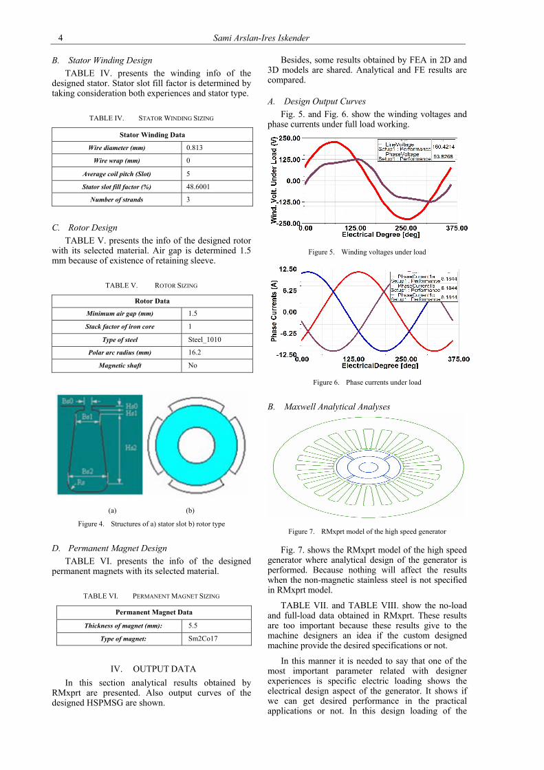
(a) (b)
Figure 4. Structures of a) stator slot b) rotor type
D. Permanent Magnet Design
TABLE VI. presents the info of the designed permanent magnets with its selected material.
TABLE VI. PERMANENT MAGNET SIZING
Permanent Magnet Data
Thickness of magnet (mm): 5.5
Type of magnet: Sm2Co17
IV. OUTPUT DATA
In this section analytical results obtained by RMxprt are presented. Also output curves of the designed HSPMSG are shown.
Besides, some results obtained by FEA in 2D and 3D models are shared. Analytical and FE results are compared.
A. Design Output Curves
Fig. 5. and Fig. 6. show the winding voltages and phase currents under full load working.
Figure 5. Winding voltages under load
Figure 6. Phase currents under load
B. Maxwell Analytical Analyses
Figure 7. RMxprt model of the high speed generator
Fig. 7. shows the RMxprt model of the high speed generator where analytical design of the generator is performed. Because nothing will affect the results when the non-magnetic stainless steel is not specified in RMxprt model.
TABLE VII. and TABLE VIII. show the no-load and full-load data obtained in RMxprt. These results are too important because these results give to the machine designers an idea if the custom designed machine provide the desired specifications or not.
In this manner it is needed to say that one of the most important parameter related with designer experiences is specific electric loading shows the electrical design aspect of the generator. It shows if we can get desired performance in the practical applications or not. In this design loading of the
Design Aspects of a 26500-r/min, 2-kW High-Speed Permanent Magnet Synchronous Generator for Turbomachinery Systems
5
generator is identified according to the cooling type, usage area and the duty cycle of the high speed generator wrt. obtained experiences.
TABLE VII. NO LOAD OPERATION
No-Load Magnetic Data
Stator teeth B (T) 1.061
Stator yoke B (T) 0.741
Rotor yoke B (T) 1.529
Airgap B (T) 0.613
Cogging torque (N.m) 0.04
TABLE VIII. FULL LOAD OPERATION
Full-Load Magnetic Data
Specific electric loading (A/mm) 30.17
Iron core loss (W) 44.92
Armature copper loss (W) 36.99
Efficiency (%) 96.14
Output power (kW) 2.026
Rated torque (N.m) 0.765
Current density (A/m2) 5.25E+006
C. Maxwell 2D&3D Finite Element Analyses (FEA)
In this section 2D and 3D analysis results of the analytically designed high speed generator are presented. The analyses are done one fourth of the whole generator body to make the analyses faster. Boundary conditions are assigned as master and slave and fields are restricted inside of the boundary conditions with zero vector potential.
The energy in the outside line of the model is assumed zero in FEA. If the boundary conditions are not determined correctly it is surely known that the results will be wrong. In this work the structure of the high speed generator is based on the boundaries which are equal and greater than the model boundaries.
(a) (b)
Figure 8. FEA model a) 2D and b) 3D
Fig. 8. shows the 2D and 3D finite element analysis model of the designed high speed generator. In the FEA retaining sleeve also took into the consideration to get more accurate results.
D. 2D FEA No-Load Operation Results
No-load operation analysis results consist of the fields only caused by permanent magnets. In this analyses, because of no need, windings are not considered. Note that the assigned meshes are too important for the accuracy and the time duration of the analyses. To get more accurate results, more intensive meshes are assigned to sensitive areas like stator slot teethes and magnets whereas surface meshes are assigned to less sensitive areas like yoke of the stator and the rotor so that time duration reduced as in Fig. 9.
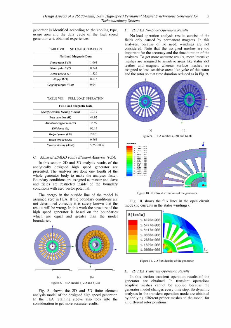
(a) (b)
Figure 9. FEA meshes a) 2D and b) 3D
Figure 10. 2D flux distributions of the generator
Fig. 10. shows the flux lines in the open circuit mode (no currents in the stator windings).
Figure 11. 2D flux density of the generator
E. 2D FEA Transient Operation Results
In this section transient operation results of the generator are obtained. In transient operations adaptive meshes cannot be applied because the generator model changes every time step. So dynamic analyses in the transient operation mode are obtained by applying different proper meshes to the model for all different rotor positions.
Sami Arslan-Ires Iskender
6
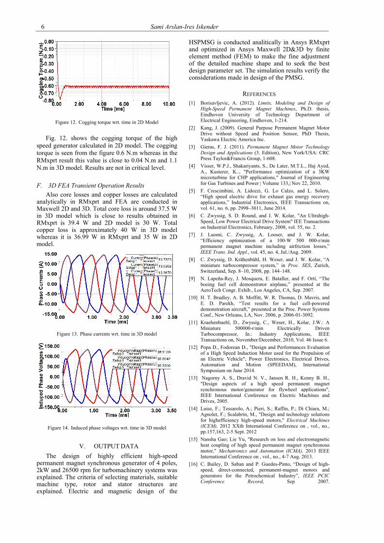
Figure 12. Cogging torque wrt. time in 2D Model
Fig. 12. shows the cogging torque of the high speed generator calculated in 2D model. The cogging torque is seen from the figure 0.6 N.m whereas in the RMxprt result this value is close to 0.04 N.m and 1.1 N.m in 3D model. Results are not in critical level.
F. 3D FEA Transient Operation Results
Also core losses and copper losses are calculated analytically in RMxprt and FEA are conducted in Maxwell 2D and 3D. Total core loss is around 37.5 W in 3D model which is close to results obtained in RMxprt is 39.4 W and 2D model is 30 W. Total copper loss is approximately 40 W in 3D model whereas it is 36.99 W in RMxprt and 35 W in 2D model.
Figure 13. Phase currents wrt. time in 3D model
Figure 14. Induced phase voltages wrt. time in 3D model
V. OUTPUT DATA
The design of highly efficient high-speed permanent magnet synchronous generator of 4 poles, 2kW and 26500 rpm for turbomachinery systems was explained. The criteria of selecting materials, suitable machine type, rotor and stator structures are explained. Electric and magnetic design of the
HSPMSG is conducted analitically in Ansys RMxprt and optimized in Ansys Maxwell 2D&3D by finite element method (FEM) to make the fine adjustment of the detailed machine shape and to seek the best design parameter set. The simulation results verify the considerations made in design of the PMSG.
REFERENCES [1] Borisavljevic, A. (2012). Limits, Modeling and Design of
High-Speed Permanent Magnet Machines, Ph.D. thesis, Eindhoven University of Technology Department of Electrical Engineering, Eindhoven, 1-214.
[2] Kang, J. (2009). General Purpose Permanent Magnet Motor Drive without Speed and Position Sensor, PhD Thesis, Yaskawa Electric America Inc.
[3] Gieras, F. J. (2011). Permanent Magnet Motor Technology Design and Applications (3. Edition), New York/USA: CRC Press Taylor&Francis Group, 1-608.
[4] Visser, W.P.J., Shakariyants, S., De Later, M.T.L., Haj Ayed, A., Kusterer, K.., "Performance optimization of a 3KW microturbine for CHP applications," Journal of Engineering for Gas Turbines and Power | Volume 133,| Nov 22, 2010.
[5] F. Crescimbini, A. Lidozzi, G. Lo Calzo, and L. Solero, “High speed electric drive for exhaust gas energy recovery applications,” Industrial Electronics, IEEE Transactions on, vol. 61, no. 6, pp. 2998–3011, June 2014.
[6] C. Zwyssig, S. D. Round, and J. W. Kolar, "An Ultrahigh-Speed, Low Power Electrical Drive System" IEE Transactions on Industrial Electronics, February, 2008, vol. 55, no. 2.
[7] J. Luomi, C. Zwyssig, A. Looser, and J. W. Kolar, “Efficiency optimization of a 100-W 500 000-r/min permanent magnet machine including airfriction losses,” IEEE Trans. Ind. Appl., vol. 45, no. 4, Jul./Aug. 2009.
[8] C. Zwyssig, D. Krähenbühl, H. Weser, and J. W. Kolar, “A miniature turbocompressor system,” in Proc. SES, Zurich, Switzerland, Sep. 8–10, 2008, pp. 144–148.
[9] N. Lapeña-Rey, J. Mosquera, E. Bataller, and F. Ortí, “The boeing fuel cell demonstrator airplane,” presented at the AeroTech Congr. Exhib., Los Angeles, CA, Sep. 2007.
[10] H. T. Bradley, A. B. Moffitt, W. R. Thomas, D. Mavris, and E. D. Parekh, “Test results for a fuel cell-powered demonstration aircraft,” presented at the Proc. Power Systems Conf., New Orleans, LA, Nov. 2006, p. 2006-01-3092.
[11] Kraehenbuehl, D., Zwyssig, C., Weser, H., Kolar, J.W.: A Miniature 500000-r/min Electrically Driven Turbocompressor, In.: Industry Applications, IEEE Transactions on, November/December, 2010, Vol. 46 Issue 6.
[12] Popa D., Fodorean D., "Design and Performances Evaluation of a High Speed Induction Motor used for the Propulsion of an Electric Vehicle", Power Electronics, Electrical Drives, Automation and Motion (SPEEDAM), International Symposium on June 2014.
[13] Nagorny A. S., Dravid N. V., Jansen R. H., Kenny B. H., "Design aspects of a high speed permanent magnet synchronous motor/generator for flywheel applications", IEEE International Conference on Electric Machines and Drives, 2005.
[14] Luise, F.; Tessarolo, A.; Pieri, S.; Raffin, P.; Di Chiara, M.; Agnolet, F.; Scalabrin, M., "Design and technology solutions for highefficiency high-speed motors," Electrical Machines (ICEM), 2012 XXth International Conference on , vol., no., pp.157,163, 2-5 Sept. 2012
[15] Nansha Gao; Lie Yu, "Research on loss and electromagnetic heat coupling of high speed permanent magnet synchronous motor," Mechatronics and Automation (ICMA), 2013 IEEE International Conference on , vol., no., 4-7 Aug. 2013.
[16] C. Bailey, D. Saban and P. Guedes-Pinto, “Design of high-speed, direct-connected, permanent-magnet motors and generators for the Petrochemical Industry”, IEEE PCIC Conference Record, Sep 2007.