design and verification tools for continuous fluid flow-based microfluidic devices
DESCRIPTION
Design and Verification Tools for Continuous Fluid Flow-based Microfluidic Devices. Jeffrey McDaniel, Auralila Baez, Brian Crites, Aditya Tammewar , Philip Brisk University of California, Riverside. Asia and South Pacific Design Automation Conference Yokohama, Japan, January 23, 2013. - PowerPoint PPT PresentationTRANSCRIPT

Design and Verification Tools for Continuous Fluid Flow-based Microfluidic Devices
Jeffrey McDaniel, Auralila Baez, Brian Crites, Aditya Tammewar,
Philip BriskUniversity of California, Riverside
Asia and South Pacific Design Automation Conference
Yokohama, Japan, January 23, 2013
2
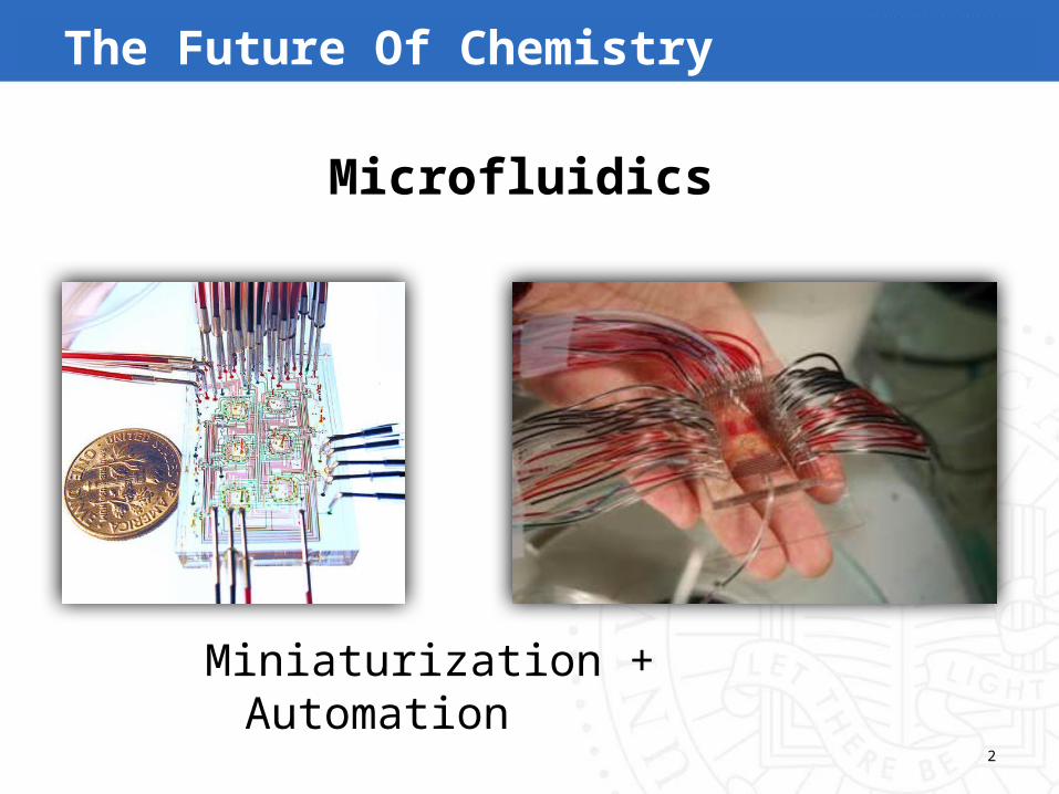
The Future Of Chemistry
Microfluidics
Miniaturization + Automation
3
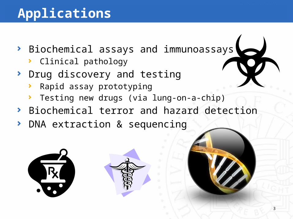
Applications
Biochemical assays and immunoassaysClinical pathology
Drug discovery and testingRapid assay prototypingTesting new drugs (via lung-on-a-chip)
Biochemical terror and hazard detectionDNA extraction & sequencing

4
Design of Continuous Fluid-flow LoCs
AutoCADDraw each layer of the chip manuallyAkin to transistor-level design of ICs with manual wire routing
Limited AutomationMulti-layer soft lithography
[Amin et al., ICCD 2009][Mihass et al. CASES 2011 & 2012]
Capillary dielectrophoresis[Pfeiffer et al. TCAD 2006][Hsieh and Ho, VLSI Design 2011]
This session at ASPDAC 2013
5
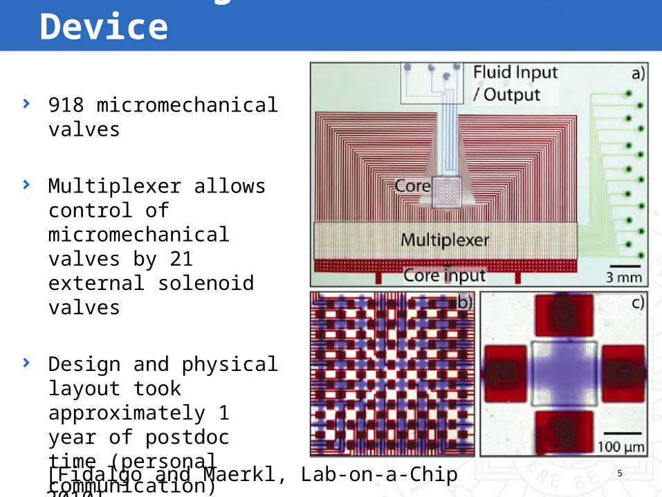
918 micromechanical valves
Multiplexer allows control of micromechanical valves by 21 external solenoid valves
Design and physical layout took approximately 1 year of postdoc time (personal communication)
EPFL Programmable Fluidic Device
[Fidalgo and Maerkl, Lab-on-a-Chip 2010]
6
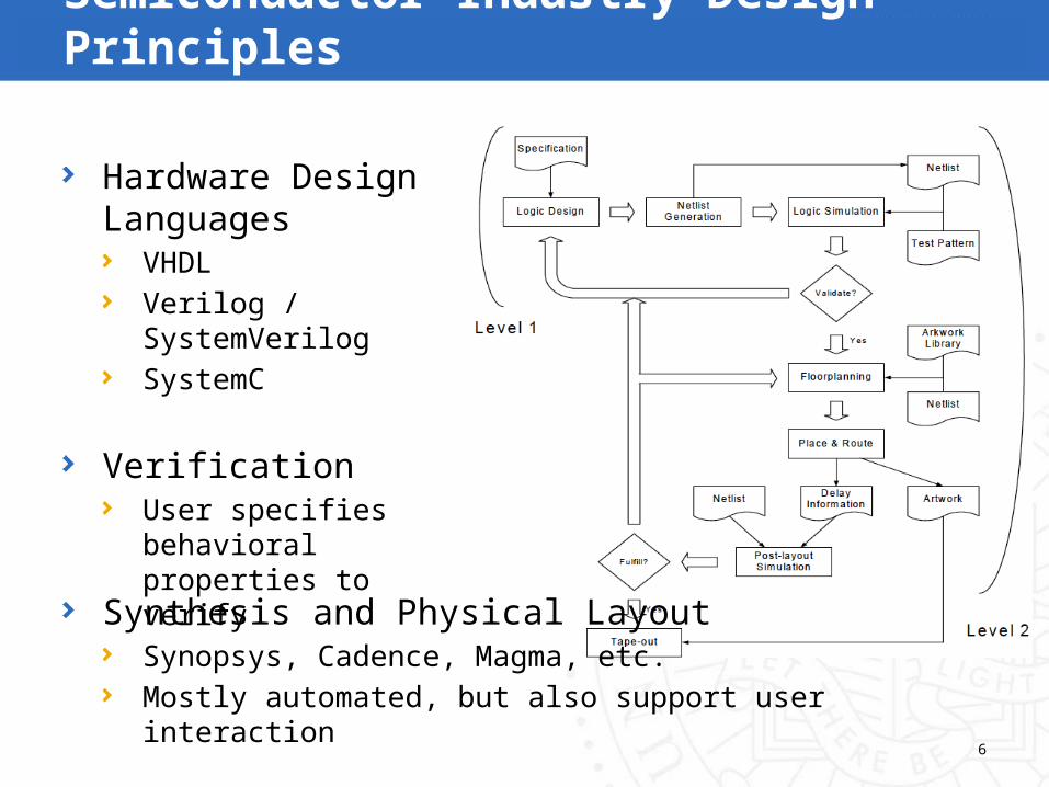
Semiconductor Industry Design Principles
Hardware Design Languages
VHDLVerilog / SystemVerilogSystemC
VerificationUser specifies behavioral properties to verify
Synthesis and Physical LayoutSynopsys, Cadence, Magma, etc.Mostly automated, but also support user interaction

7
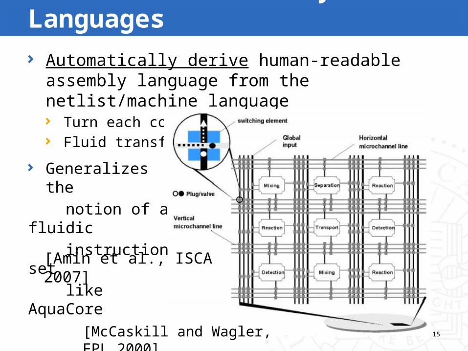
A typical LoC consists ofA collection of “components”Fluidic interconnect between components“Netlist”-like representation
Key Observation!
[Amin et al., ISCA 2007]

8
Microfluidic Hardware Design Language (MHDL)Functional Verification, Performance Simulation
Our Contributions

9
MHDL Syntax Diagram
One entity per component;entities may have optional external control
List the components in the LoC
Specify connections between components
10
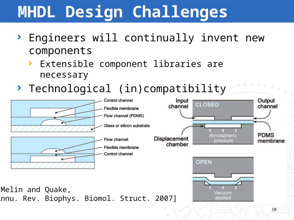
Engineers will continually invent new componentsExtensible component libraries are necessary
Technological (in)compatibility between componentsMust be part of component/library specification
MHDL Design Challenges
[Melin and Quake, Annu. Rev. Biophys. Biomol. Struct. 2007]
11
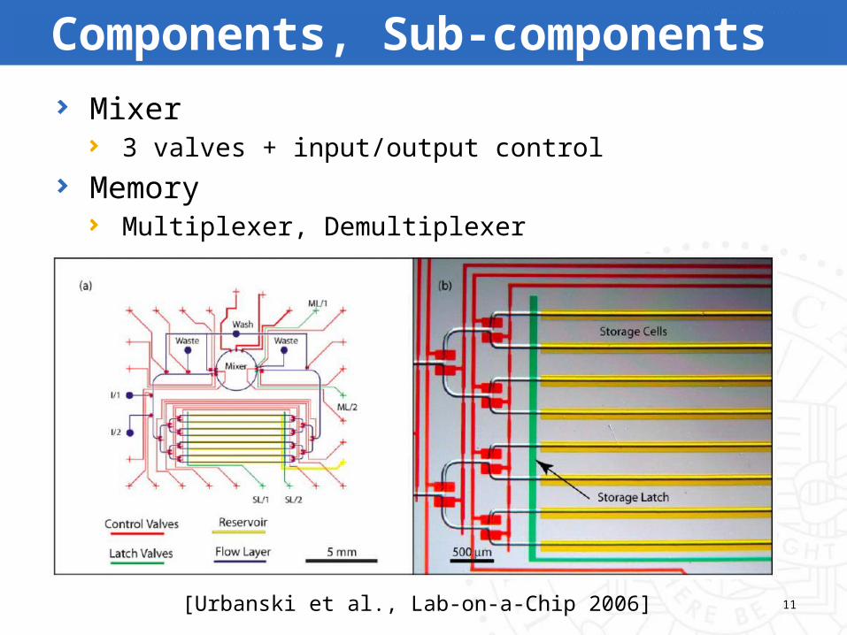
Mixer3 valves + input/output control
MemoryMultiplexer, Demultiplexer
Components, Sub-components
[Urbanski et al., Lab-on-a-Chip 2006]
12
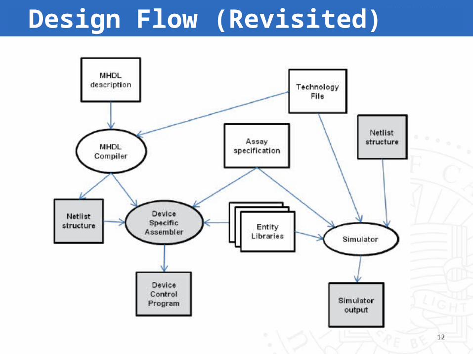
Design Flow (Revisited)
13
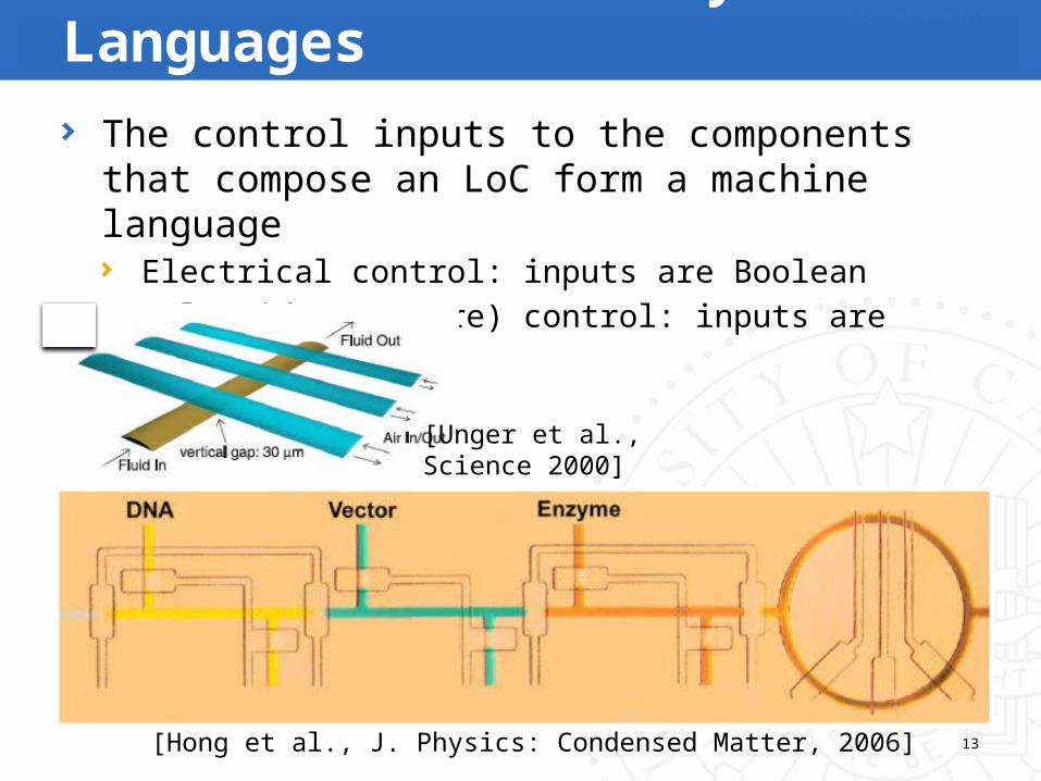
The control inputs to the components that compose an LoC form a machine language
Electrical control: inputs are BooleanSolenoid (pressure) control: inputs are real-valued
Machine and Assembly Languages
[Hong et al., J. Physics: Condensed Matter, 2006]
[Unger et al., Science 2000]

A vector of control values is like a machine language instruction
A sequence of vectors forms a machine language program
14
Machine and Assembly Languages
[Jensen et al., Lab-on-a-Chip 2010]
15
Automatically derive human-readable assembly language from the netlist/machine language
Turn each component on/off (etc.)Fluid transfers
Machine and Assembly Languages
[McCaskill and Wagler, FPL 2000]
Generalizes the notion of a fluidic instruction set like AquaCore [Amin et al., ISCA 2007]

16
Design Flow (Revisited)

17
Device-Specific AssemblerInputs
Netlist representation of an LoCAssembly language assay specification
Functional verificationCan the netlist execute the assay?
Is there a component to execute each operation?Are all required fluid transfers possible?
Output: Device Control ProgramSequence of control vectors to execute the assay

18
SimulationPerformance Evaluation (Latency)
Assay specification (e.g., MIX for 30s)Fluid transfer overhead
Hagen-Poisseuile Equation: T = V/QV: Volume of fluid to transferQ: Volumetric flow rate
Volumetric Flow Rate: Q = ΔPπd4 / 128μL
ΔP: Pressure dropμ: Fluid viscosityd: Channel diameter – not known until after physical layoutL: Channel length – not known until after physical layout
Absent layout information, the user can specify d and L
19
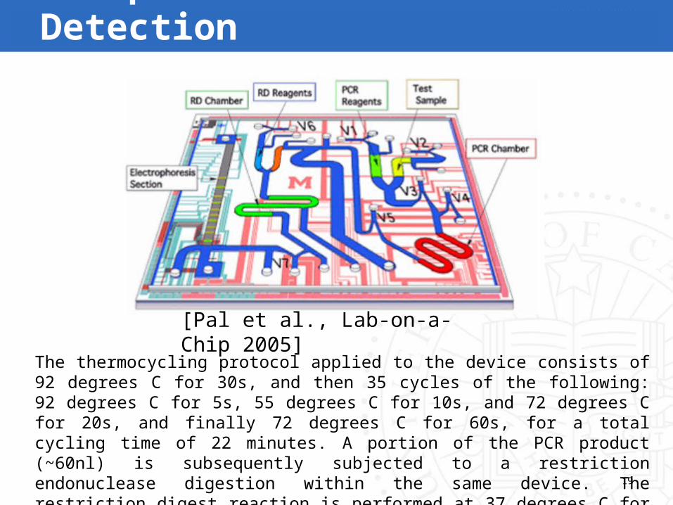
Example: Influenza Detection
The thermocycling protocol applied to the device consists of 92 degrees C for 30s, and then 35 cycles of the following: 92 degrees C for 5s, 55 degrees C for 10s, and 72 degrees C for 20s, and finally 72 degrees C for 60s, for a total cycling time of 22 minutes. A portion of the PCR product (~60nl) is subsequently subjected to a restriction endonuclease digestion within the same device. The restriction digest reaction is performed at 37 degrees C for 10 min.
[Pal et al., Lab-on-a-Chip 2005]
20
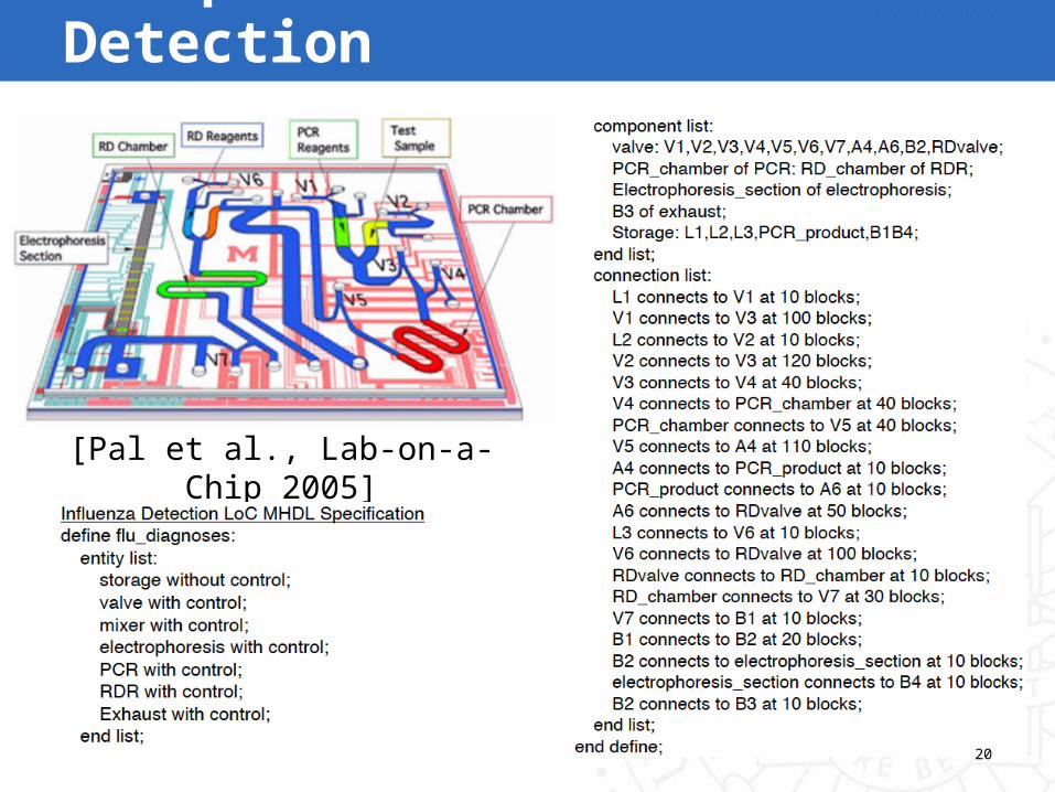
Example: Influenza Detection
[Pal et al., Lab-on-a-Chip 2005]
21
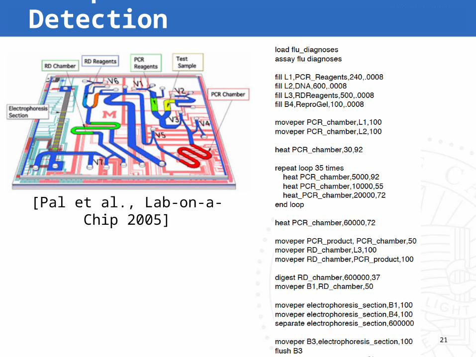
Example: Influenza Detection
[Pal et al., Lab-on-a-Chip 2005]
22
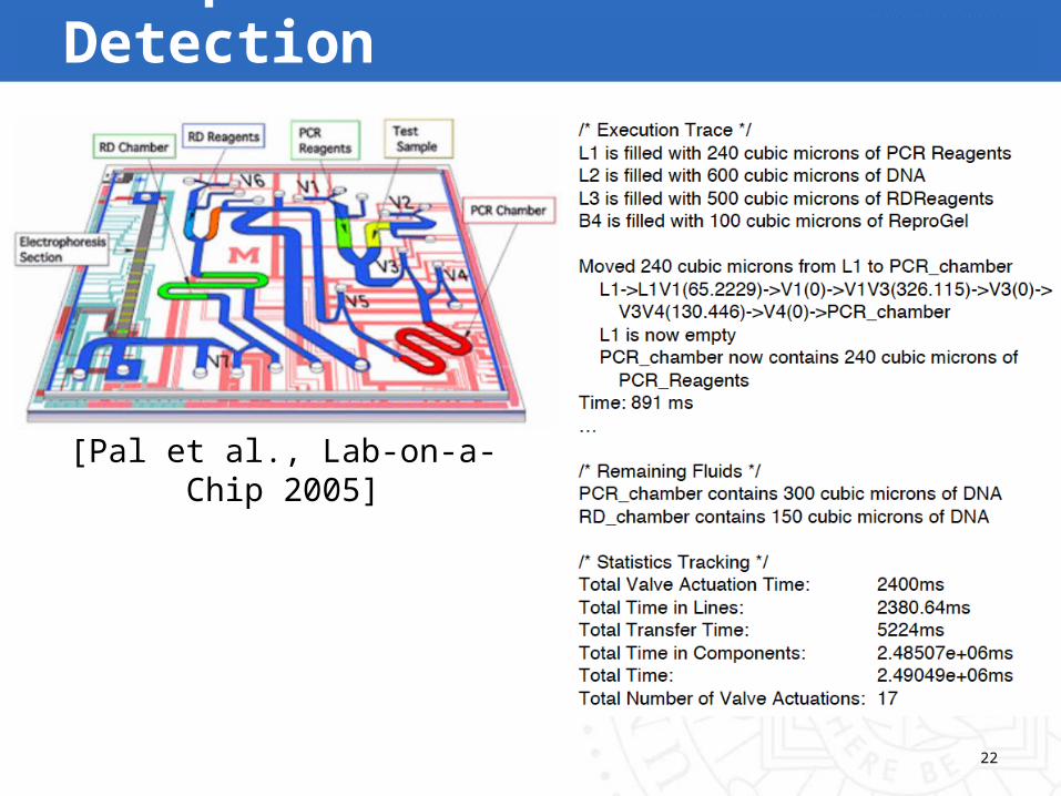
Example: Influenza Detection
[Pal et al., Lab-on-a-Chip 2005]

23
Conclusion and Future WorkContinuous Fluid Flow LoC Specification
Technology-independent MHDL languageVerification and simulation framework
Machine Language LoC InterfaceAutomatically derive human-readable assemblyHuman specifies assay in assembly
Future WorkCompile high-level language to assemblyPhysical design flow(s)