design and prototype of mobile robots for rescue ...kececi/rescuerobot.pdf · 732 design and...
TRANSCRIPT
Robotica (2009) volume 27, pp. 729–737. © 2008 Cambridge University Pressdoi:10.1017/S0263574708005109 Printed in the United Kingdom
Design and prototype of mobile robots for rescue operationsE. Faruk Kececi∗
Department of Mechanical Engineering, Izmir Institute of Technology, Urla, Izmir 35430, Turkey
(Received in Final Form: August 21, 2008. First published online: September 30, 2008)
SUMMARYThis study concerns the design and prototype of fourdifferent mobile robot platforms for rescue robot operationsafter an earthquake. At first, a test field is constructed torepresent a mildly damaged earthquake zone. The test fieldconsists of eight different sections: sand, gravel, ditch, water,bridge, incline, decline, and turn. The mechanical structure,electronics, software, communication, and possible sensorysystems are explained. After the robots are manufactured,they are physically tested for their performance in the testfield for 18 different parameters. The test results show theeffective body structure. Challenges of the rescue robotdesign are explained and future expectations are given.
KEYWORDS: All terrain; Prototype robot design; Rescuerobotics.
1. IntroductionRescue robotics focuses on designing robots to help peopleafter disasters. When time and equipments are limited, robotscan be used to save lives, and emergency responders do notneed to risk their own lives during the rescue operations.One of the most common disasters for which rescue robotsare being used is earthquake. The general requirements andexpectations for rescue robots are given in refs. [1–8].
In mobile robot applications, the mission time, wirelessoperating distance, rough terrain capability, and falldurability become important limitations of the design. Forrescue robots, since the robot needs to penetrate into therubble, additional limitations to mobile robot are required;the rescue robot should be small and light enough not todisturb unstable objects in the rubble.
The early efforts of rescue robotics started with theRoboCup Rescue competition to increase interest andresearch in the field.9,10 The main problem of rescue robotdesign is to have a mobile base which can go over on arough terrain. The concept of rough terrain is described inrefs. [9–11], where the damage to the building is describedwith different color of courses from yellow to orange to red,illustrating the terrain difficulty from light to moderate tocomplex.
When rescue robots are categorized, the locomotion ofthe robots is mostly either as tracked vehicles12,13 or snake-type robots.14,15 It is also suggested that if they can changetheir shapes, this will assist them to climb and maneuverin confined spaces.16 The reason a wheeled robot cannot be
* Corresponding author. E-mail: [email protected]
used easily in rescue operations is that, the robot will haveless ability to overcome the obstacles because of the fact thata wheel cannot go over an obstacle bigger than its radius.
However, in order to combine the advantages ofwheeled and legged drive systems, leg-wheel structures arecreated.17,18 In this type of design, a wheel is attached at theend of the leg structure. When the robot is on a flat surface,it can use the wheel to go faster. When the wheels cannot beused because of the obstacles or surface irregularities (suchas sand) the wheels are locked and the legs are used to passthe region. The difficulty of such a design is that the wheelat the end of the leg causes too much weight and requires theleg motors to be larger.
The mechanical design advantage of a snake-type robotis that it can be small in cross section, which enables therobot to penetrate into the rubble easily compared to atracked vehicle.14,15,19 However, the snake-type robots aremore difficult to control and their load to body weight ratiois smaller than a tracked-type robot. Most of the time, thistype of a robot is used for observation. Especially some of thesnake robot designs20,21 required to use small wheels underthe each segment of the robot. Unfortunately, this type of amechanical structure does not work inside rubble since thedirt fills into the gaps too easily.
Special designs, such as a ball structure,22 are also tried.This type of a robot could penetrate into rubble; however,since the robot cannot move actively they cannot cover allthe rubble and a system needs to be developed to trackthe position of the robot inside the ruble. A similar ideais achieved by a core-bored robot, but this types of robot canonly provide visual feedback to the areas it can reach.23
There are also more advanced designs where each side ofthe robot has a track and this design allows the robot to moveno matter which of its surfaces is in contact with the ground.24
Micro robotics has also been used in debris; however, thistype of a system requires many robots to be effective.25 Smallhumanoid robots can be used in victim exploration, but theservo motor technology needs to be improved for this typeof robot to be strong enough to maneuver on rough terrain.26
Adding one degree of freedom arm on the robot also helpsto balance the robot when it is working in the rubble.27
At the World Trade Center, existing mobile robots wereused for surveillance, but most of these robots weredesigned for military applications, not specifically for rescueoperations in an earthquake zone.12,28,29
In earlier studies, the problems encountered with mobilerobots in a rescue field are explained, but the design processof the robot is not mentioned. This paper explains themechanical design procedure and prototype stages of four
730 Design and prototype of mobile robots for rescue operations
different types of mobile robots which are designed for amildly damaged earthquake zone. Moreover, the robots areevaluated for their performance and the design challenges inthe procedure of robot design are summarized.
2. Problem DefinitionThe biggest problem in rescue robot design is that the rubbleafter an earthquake is not standard, and for any given rubbleit can be completely different. However, the damage isdescribed as light, mild, and heavy depending on the brokenthings and fallen appliances.11
Apart from the geometrical difficulties, the objects in anyhouse become obstacles for the robots. Even though some ofthese obstacles such as chairs, books, or even sofas can beguessed, places like kitchens or offices are harder to model.In any kitchen, the glassware and china breaks and forms oddshape obstacles. In the offices, little office supplies, such asa paper clip or papers create very difficult obstacles to pass.
In this study, the problem is described in two parts: thefield and the limitations on the robot. The described fieldrepresents a mildly damaged building after an earthquakewhere small things have fallen on the floor but not the bigappliances. The limitations on the robot force the robot tobe on a reasonable scale to the obstacles. If there are nophysical limitations on the robot, the natural intention willbe making the robot as big as possible to overcome anyobstacle. However, in general, robots for rescue operationsshould be small to penetrate the rubble better and shouldbe light in order not to apply too much pressure on trappedpeople, or unstable parts of the building.
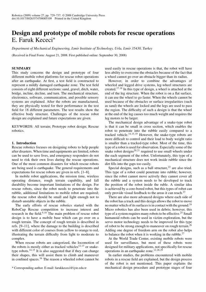
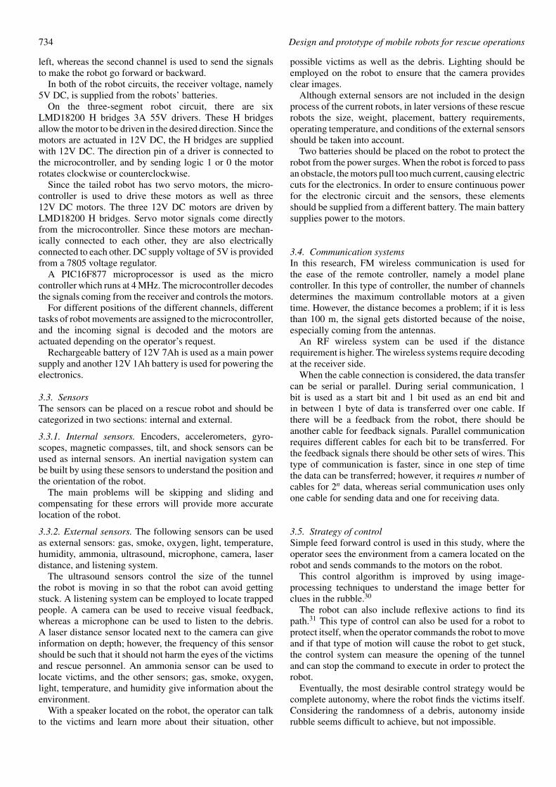
2.1. The test fieldThe test field to represent the earthquake zone is designed tohave different types of terrain properties. The field is shownin Fig. 1 and the details of the terrain are explained later.Wooden boxes of dimensions 50 cm to 100 cm are made andthese boxes are filled with sand, gravel, and water. Betweenthe gravel-filled box and water-filled box, a space is used asa ditch where the falling and climbing abilities of the robotsare tested.
Sections of the test field are as follows:
1. Sand terrain: Traction control of the designed robot on asoft terrain is the purpose of this section. The sand grainsize is smaller than 1 mm.
2. Gravel terrain: Gravel size is smaller than 30 mm, whichacts like broken objects after an earthquake.
3. Falling into the ditch: The robot needs to fall 20 cm andduring this fall it should not get damaged mechanicallyor electronically.
4. Climbing up the ditch: The robot needs to have the abilityto climb over a 20-cm straight wall.
5. Water pool: In order to test the water resistance ability ofthe robot, the robot needs to pass the water pool whichhas a 5-cm depth.
6. Passing under the bridge: In order to limit the totalheight, the robot should travel under the bridge witha height of 12 cm.
Fig. 1. The track and its different sections.
7. Inclined surface: The robot should climb a 15◦ ramp,which requires extra engine power.
8. Peak: The ground clearance of the robot becomesimportant at this stage for the robot not to get stuckat the peak point.
9. Declined surface: During the travel on the declinedsurface the robot should have breaking ability not tofall.
10. Turn: The steering ability of the robot is tested, wherethe robot needs to make a U turn with a radius of 1.5 m.
2.2. Robot limitationsThe limitations on the robot were:
1. Size: The robot must be smaller than A4 size paper(210 mm × 297 mm), but there is no initial heightlimitation.
2. Load: The robot needs to carry a load (120 mm ×50 mm × 20 mm, length × width × depth; and 120 g).
3. Trajectory: The robot should go through each field.4. Control: The robot needs to be remote controlled.
When the limitations on the robot are considered with thefield, there are some limitations which are not explicitlymentioned. Different terrain types on the test field requirethe robot to have a durable locomotion system. Falling downand climbing 20-cm height requires a suspension system anda climbing mechanism. In order to be able to turn, the roboteither should have a steering mechanism or it should skid
Design and prototype of mobile robots for rescue operations 731
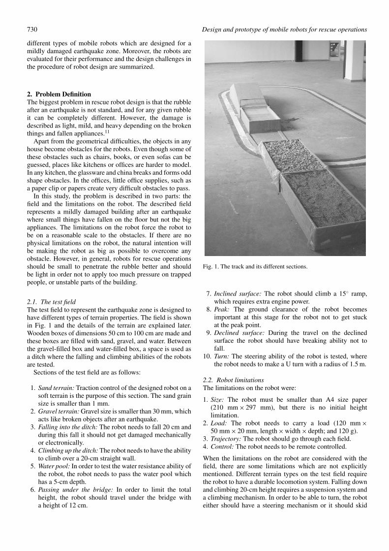
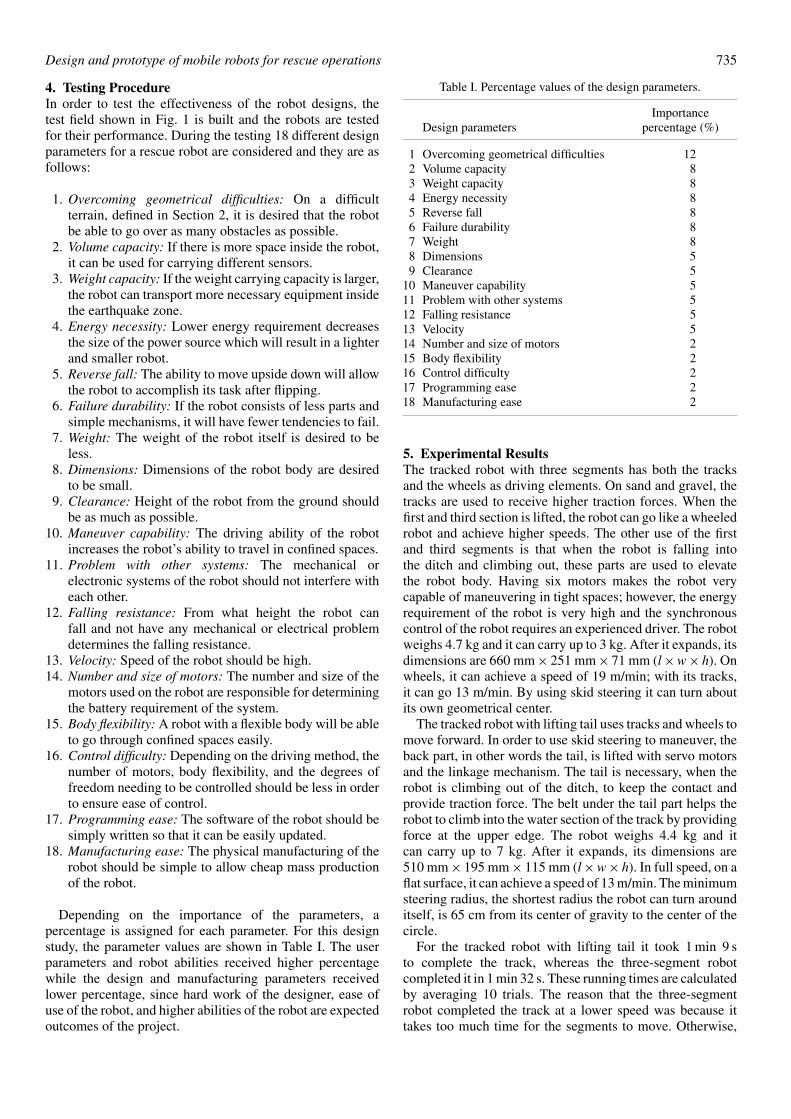
Fig. 2. Design of the tracked robot with three segments and prototype robot.
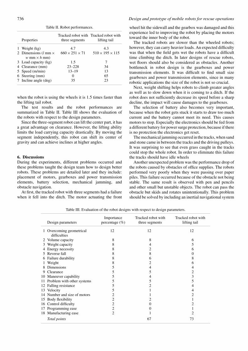
Fig. 3. Design of the tracked robot with lifting tail and prototype robot.
Fig. 4. Design of the rocker robot and prototype robot.
steer. The size of the robot compared to the distance it shouldclimb and the bridge height it should pass under limits useof big wheels or tracks. Carrying the load imposes the centerof the gravity to be calculated very carefully.
3. PrototypesWhen the prototypes are being designed and built, the robotlimitations are kept in mind and they are designed to pass thetest field. The following subsections explain the mechanical,hardware, software, sensory, and control systems of therobotic platforms.
3.1. Mechanical designIn the mechanical design stage, six different solutions arefound. One of these solutions included a hook to throw tothe bridge and pull the robot out of the ditch. Another designused a rocket engine to fly down to and out of the ditch.These ideas are rejected, because the control of the system isthought to be too difficult.
The other four solutions are preceding and the designpictures and actual robots are showed in Figs. 2–5.
The three-segment tracked vehicle shown in Fig. 2,designed to have driving motors for the left side tracks placedtoward the front side, and for the right side placed in theback. This design ensures that the weight of the motors is

732 Design and prototype of mobile robots for rescue operations
Fig. 5. Design of the wheeled robot with lifting horn and prototype robot.
distributed equally. Electronic equipment is placed in themiddle because the middle can be lifted while the robot ispassing through the water pool. Batteries are positioned atthe first and third segments because of the lack of space onthe middle segment but the connections of the batteries arekept close to the middle segment so that the batteries can bemerged into water up to their connection level.
The main body of the three-segment tracked robot couldnot be manufactured with milling operation, because themaximum depth of the cutting tool was not enough. Thisrestriction forced the main body part to be manufactured byfolding operations. After the aluminum plate was cut with alaser cutter, it was folded with a folding machine.
On the tracked vehicle with lifting tail design (Fig. 4), inorder to protect the electronics, the electronic circuits areplaced inside a protective layer, namely inside a balloon.In this design, two servo motors connected with a linkagemechanism are used to lift the tail, since using two motorsinstead of one distributes the weight and space of theactuators evenly on the tail part. Since it was not possibleto find a track with teeth at both sides for the design in Fig. 5,a timing belt was improved by gluing rubber pieces to haveteeth on the outer side of the belt.
The rocker robot has 6 × 6 drive ability and it can go upsidedown. However, the six motors and the battery on the robottake three-fourth of the space inside robot; therefore, thereis an insufficient amount of space for the robot to carry afunctional load.
The wheeled robot with lifting horn has six wheels, anAckerman steering system and a leverage system for liftingthe robot’s body. The body flexibility is considered to createconstant contact between the wheels of the robot and theground during the climbing of the ditch. However, it was thisflexibility which caused the robot skid and slide when it wasin motion.
Initially these four robots were tested to see if theycould pass the minimum requirements of an earthquakerescue robot. These requirements are: mobility and accuratepositioning and orientation. The testing was based oneach robot completing an elliptical path. This test provedthat wheeled robots were not able to meet the minimumrequirements. Both robots had problems with skidding and
sliding; therefore, their design is considered unremarkableand further testing was not performed.
3.2. Hardware and communication system softwareThe hardware of the tracked robots consists mainly offive parts: actuators, remote control, motor drivers, micro-computer, and battery.
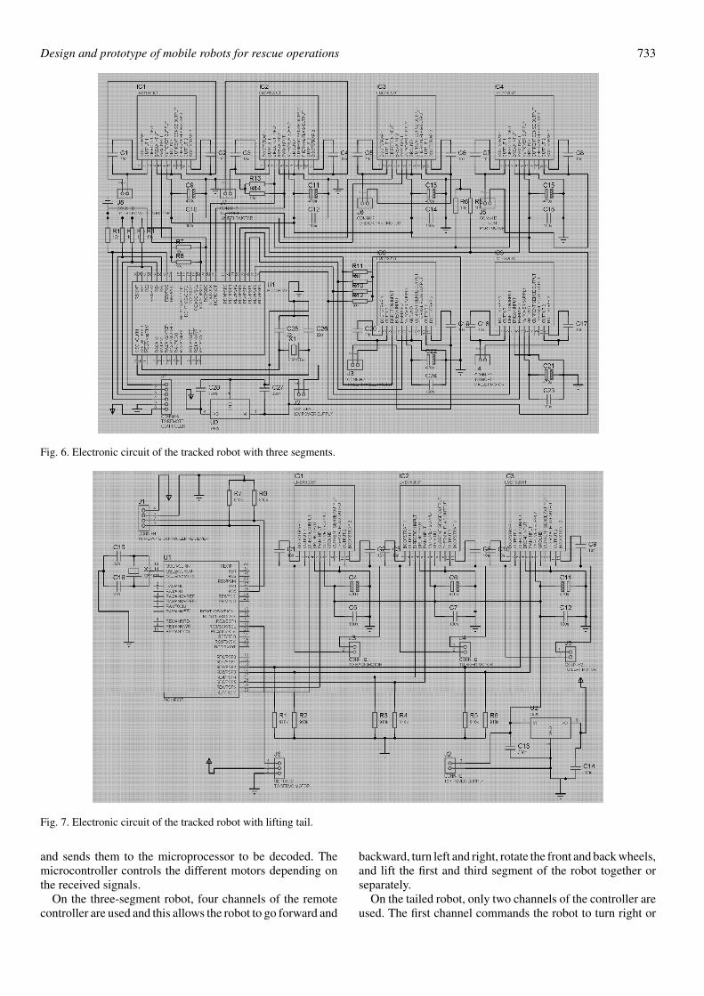
Figure 6 shows the electronic circuit for the tracked robotwith three segments. Where six 120 rpm 12V DC motorsare controlled. Two of these motors are used to lift theend segments whereas the other two motors are used forrotating the wheels at the end of these sections clockwiseand counterclockwise. The main body of the robot is drivenwith tracks by two motors. The microcontroller, PIC16F877,controls six motors through six LMD18200T 3 A, 55VH bridges. Seven thousand eight hundred and five voltageregulator (KA7805) provides the 5V DC to the circuit. Thecommands from the user are transferred to the robot with aremote controller, which is connected to the PORTB3–6 pinsof the microcontroller.
The tracked robot with lifting tail has two standard servomotors and three 120 rpm 12V DC motors. The DC motorsare used to drive the left and right tracks as well as theback wheels. The tracks are used both in driving backwardand forward as well as turning. The rear wheels only assistin backward and forward driving. The servo motors areconnected to each other and lift a small idle wheel at the backto lift the rear wheels during the turns, ensuring that the robotturns about its main body’s geometrical center. This turningpoint allows the robot to have less friction during the turns.
Figure 7 shows the circuit diagram for the tracked robotwith lifting tail. A PIC16F877 microcontroller drives threeLMD18200T H bridges and two servo motors. The twoservos are driven simultaneously, so they are connected tothe same pin of the microcontroller. Seven thousand eighthundred and five voltage regulator provides 5V DC to thecircuit.
In order to control the robots, a five-channel 33-MHz FMremote controller is used. This remote controller consistsof two parts: the transmitter and the receiver. The operatoruses the transmitter to send the desired commands to therobot and the receiver placed on the robot catches the signals
Design and prototype of mobile robots for rescue operations 733
Fig. 6. Electronic circuit of the tracked robot with three segments.
Fig. 7. Electronic circuit of the tracked robot with lifting tail.
and sends them to the microprocessor to be decoded. Themicrocontroller controls the different motors depending onthe received signals.
On the three-segment robot, four channels of the remotecontroller are used and this allows the robot to go forward and
backward, turn left and right, rotate the front and back wheels,and lift the first and third segment of the robot together orseparately.
On the tailed robot, only two channels of the controller areused. The first channel commands the robot to turn right or
734 Design and prototype of mobile robots for rescue operations
left, whereas the second channel is used to send the signalsto make the robot go forward or backward.
In both of the robot circuits, the receiver voltage, namely5V DC, is supplied from the robots’ batteries.
On the three-segment robot circuit, there are sixLMD18200 H bridges 3A 55V drivers. These H bridgesallow the motor to be driven in the desired direction. Since themotors are actuated in 12V DC, the H bridges are suppliedwith 12V DC. The direction pin of a driver is connected tothe microcontroller, and by sending logic 1 or 0 the motorrotates clockwise or counterclockwise.
Since the tailed robot has two servo motors, the micro-controller is used to drive these motors as well as three12V DC motors. The three 12V DC motors are driven byLMD18200 H bridges. Servo motor signals come directlyfrom the microcontroller. Since these motors are mechan-ically connected to each other, they are also electricallyconnected to each other. DC supply voltage of 5V is providedfrom a 7805 voltage regulator.
A PIC16F877 microprocessor is used as the microcontroller which runs at 4 MHz. The microcontroller decodesthe signals coming from the receiver and controls the motors.
For different positions of the different channels, differenttasks of robot movements are assigned to the microcontroller,and the incoming signal is decoded and the motors areactuated depending on the operator’s request.
Rechargeable battery of 12V 7Ah is used as a main powersupply and another 12V 1Ah battery is used for powering theelectronics.
3.3. SensorsThe sensors can be placed on a rescue robot and should becategorized in two sections: internal and external.
3.3.1. Internal sensors. Encoders, accelerometers, gyro-scopes, magnetic compasses, tilt, and shock sensors can beused as internal sensors. An inertial navigation system canbe built by using these sensors to understand the position andthe orientation of the robot.
The main problems will be skipping and sliding andcompensating for these errors will provide more accuratelocation of the robot.
3.3.2. External sensors. The following sensors can be usedas external sensors: gas, smoke, oxygen, light, temperature,humidity, ammonia, ultrasound, microphone, camera, laserdistance, and listening system.
The ultrasound sensors control the size of the tunnelthe robot is moving in so that the robot can avoid gettingstuck. A listening system can be employed to locate trappedpeople. A camera can be used to receive visual feedback,whereas a microphone can be used to listen to the debris.A laser distance sensor located next to the camera can giveinformation on depth; however, the frequency of this sensorshould be such that it should not harm the eyes of the victimsand rescue personnel. An ammonia sensor can be used tolocate victims, and the other sensors; gas, smoke, oxygen,light, temperature, and humidity give information about theenvironment.
With a speaker located on the robot, the operator can talkto the victims and learn more about their situation, other
possible victims as well as the debris. Lighting should beemployed on the robot to ensure that the camera providesclear images.
Although external sensors are not included in the designprocess of the current robots, in later versions of these rescuerobots the size, weight, placement, battery requirements,operating temperature, and conditions of the external sensorsshould be taken into account.
Two batteries should be placed on the robot to protect therobot from the power surges. When the robot is forced to passan obstacle, the motors pull too much current, causing electriccuts for the electronics. In order to ensure continuous powerfor the electronic circuit and the sensors, these elementsshould be supplied from a different battery. The main batterysupplies power to the motors.
3.4. Communication systemsIn this research, FM wireless communication is used forthe ease of the remote controller, namely a model planecontroller. In this type of controller, the number of channelsdetermines the maximum controllable motors at a giventime. However, the distance becomes a problem; if it is lessthan 100 m, the signal gets distorted because of the noise,especially coming from the antennas.
An RF wireless system can be used if the distancerequirement is higher. The wireless systems require decodingat the receiver side.
When the cable connection is considered, the data transfercan be serial or parallel. During serial communication, 1bit is used as a start bit and 1 bit used as an end bit andin between 1 byte of data is transferred over one cable. Ifthere will be a feedback from the robot, there should beanother cable for feedback signals. Parallel communicationrequires different cables for each bit to be transferred. Forthe feedback signals there should be other sets of wires. Thistype of communication is faster, since in one step of timethe data can be transferred; however, it requires n number ofcables for 2n data, whereas serial communication uses onlyone cable for sending data and one for receiving data.
3.5. Strategy of controlSimple feed forward control is used in this study, where theoperator sees the environment from a camera located on therobot and sends commands to the motors on the robot.
This control algorithm is improved by using image-processing techniques to understand the image better forclues in the rubble.30
The robot can also include reflexive actions to find itspath.31 This type of control can also be used for a robot toprotect itself, when the operator commands the robot to moveand if that type of motion will cause the robot to get stuck,the control system can measure the opening of the tunneland can stop the command to execute in order to protect therobot.
Eventually, the most desirable control strategy would becomplete autonomy, where the robot finds the victims itself.Considering the randomness of a debris, autonomy insiderubble seems difficult to achieve, but not impossible.
Design and prototype of mobile robots for rescue operations 735
4. Testing ProcedureIn order to test the effectiveness of the robot designs, thetest field shown in Fig. 1 is built and the robots are testedfor their performance. During the testing 18 different designparameters for a rescue robot are considered and they are asfollows:
1. Overcoming geometrical difficulties: On a difficultterrain, defined in Section 2, it is desired that the robotbe able to go over as many obstacles as possible.
2. Volume capacity: If there is more space inside the robot,it can be used for carrying different sensors.
3. Weight capacity: If the weight carrying capacity is larger,the robot can transport more necessary equipment insidethe earthquake zone.
4. Energy necessity: Lower energy requirement decreasesthe size of the power source which will result in a lighterand smaller robot.
5. Reverse fall: The ability to move upside down will allowthe robot to accomplish its task after flipping.
6. Failure durability: If the robot consists of less parts andsimple mechanisms, it will have fewer tendencies to fail.
7. Weight: The weight of the robot itself is desired to beless.
8. Dimensions: Dimensions of the robot body are desiredto be small.
9. Clearance: Height of the robot from the ground shouldbe as much as possible.
10. Maneuver capability: The driving ability of the robotincreases the robot’s ability to travel in confined spaces.
11. Problem with other systems: The mechanical orelectronic systems of the robot should not interfere witheach other.
12. Falling resistance: From what height the robot canfall and not have any mechanical or electrical problemdetermines the falling resistance.
13. Velocity: Speed of the robot should be high.14. Number and size of motors: The number and size of the
motors used on the robot are responsible for determiningthe battery requirement of the system.
15. Body flexibility: A robot with a flexible body will be ableto go through confined spaces easily.
16. Control difficulty: Depending on the driving method, thenumber of motors, body flexibility, and the degrees offreedom needing to be controlled should be less in orderto ensure ease of control.
17. Programming ease: The software of the robot should besimply written so that it can be easily updated.
18. Manufacturing ease: The physical manufacturing of therobot should be simple to allow cheap mass productionof the robot.
Depending on the importance of the parameters, apercentage is assigned for each parameter. For this designstudy, the parameter values are shown in Table I. The userparameters and robot abilities received higher percentagewhile the design and manufacturing parameters receivedlower percentage, since hard work of the designer, ease ofuse of the robot, and higher abilities of the robot are expectedoutcomes of the project.
Table I. Percentage values of the design parameters.
ImportanceDesign parameters percentage (%)
1 Overcoming geometrical difficulties 122 Volume capacity 83 Weight capacity 84 Energy necessity 85 Reverse fall 86 Failure durability 87 Weight 88 Dimensions 59 Clearance 5
10 Maneuver capability 511 Problem with other systems 512 Falling resistance 513 Velocity 514 Number and size of motors 215 Body flexibility 216 Control difficulty 217 Programming ease 218 Manufacturing ease 2
5. Experimental ResultsThe tracked robot with three segments has both the tracksand the wheels as driving elements. On sand and gravel, thetracks are used to receive higher traction forces. When thefirst and third section is lifted, the robot can go like a wheeledrobot and achieve higher speeds. The other use of the firstand third segments is that when the robot is falling intothe ditch and climbing out, these parts are used to elevatethe robot body. Having six motors makes the robot verycapable of maneuvering in tight spaces; however, the energyrequirement of the robot is very high and the synchronouscontrol of the robot requires an experienced driver. The robotweighs 4.7 kg and it can carry up to 3 kg. After it expands, itsdimensions are 660 mm × 251 mm × 71 mm (l × w × h). Onwheels, it can achieve a speed of 19 m/min; with its tracks,it can go 13 m/min. By using skid steering it can turn aboutits own geometrical center.
The tracked robot with lifting tail uses tracks and wheels tomove forward. In order to use skid steering to maneuver, theback part, in other words the tail, is lifted with servo motorsand the linkage mechanism. The tail is necessary, when therobot is climbing out of the ditch, to keep the contact andprovide traction force. The belt under the tail part helps therobot to climb into the water section of the track by providingforce at the upper edge. The robot weighs 4.4 kg and itcan carry up to 7 kg. After it expands, its dimensions are510 mm × 195 mm × 115 mm (l × w × h). In full speed, on aflat surface, it can achieve a speed of 13 m/min. The minimumsteering radius, the shortest radius the robot can turn arounditself, is 65 cm from its center of gravity to the center of thecircle.
For the tracked robot with lifting tail it took 1 min 9 sto complete the track, whereas the three-segment robotcompleted it in 1 min 32 s. These running times are calculatedby averaging 10 trials. The reason that the three-segmentrobot completed the track at a lower speed was because ittakes too much time for the segments to move. Otherwise,
736 Design and prototype of mobile robots for rescue operations
Table II. Robot performances.
Tracked robot with Tracked robot withProperties three segments lifting tail
1 Weight (kg) 4.7 4.32 Dimensions (l mm × 660 × 251 × 71 510 × 195 × 115
w mm × h mm)3 Load capacity (kg) 1.5 74 Clearance (mm) 23–228 345 Speed (m/min) 13–19 136 Steering (mm) 0 657 Incline angle (deg) 35 23
when the robot is using the wheels it is 1.5 times faster thanthe lifting tail robot.
The test results and the robot performances aresummarized in Table II. Table III shows the evaluation ofthe robots with respect to the design parameters.
Since the three-segment robot can lift the center part, it hasa great advantage on clearance. However, the lifting abilitylimits the load carrying capacity drastically. By moving thesegment independently, this robot can shift its center ofgravity and can achieve inclines at higher angles.
6. DiscussionsDuring the experiments, different problems occurred andthese problems taught the design team how to design betterrobots. These problems are detailed later and they include:placement of motors, gearboxes and power transmissionelements, battery selection, mechanical jamming, andobstacle navigation.
At first, the tracked robot with three segments had a failurewhen it fell into the ditch. The motor actuating the front
wheel hit the sidewall and the gearbox was damaged and thisexperience led to improving the robot by placing the motorstoward the inner body of the robot.
The tracked robots are slower than the wheeled robots;however, they can carry heavier loads. An expected difficultywas that when the field gets wet the robots have a difficulttime climbing the ditch. In later designs of rescue robots,wet floors should also be considered as obstacles. Anotherbottleneck in robot design is the gearboxes and powertransmission elements. It was difficult to find small sizegearboxes and power transmission elements, since in manyrobotic applications the size of the robot is not so crucial.
Next, weight shifting helps robots to climb greater anglesas well as to slow down when it is coming to a ditch. If therobot does not sufficiently decrease its speed before a sharpdecline, the impact will cause damages to the gearboxes.
The selection of battery also becomes very important,because when the robot gets stuck it starts to draw too muchcurrent and the battery cannot meet its need. This causesmotors to stop. Especially the electronics should be fed froma different battery for power surge protection, because if thereis no protection the electronics get reset.
The mechanical jamming occurred in the tracks, when sandand stone came in between the tracks and the driving pulleys.It was surprising to see that even grass caught in the trackscould stop the whole robot. In order to eliminate this failurethe tracks should have idle wheels
Another unexpected problem was the performance drop ofthe robots caused by obstacles of office supplies. The robotsperformed very poorly when they were passing over paperpiles. This failure occurred because of the obstacle not beingstable. The same result is observed with pen and pencilsand other small but unstable objects. The robot can pass theobstacle but skids and rotates unintentionally. This problemshould be solved by including an inertial navigational system
Table III. Evaluation of the robot designs with respect to design parameters.
Importance Tracked robot with Tracked robot withDesign parameters percentage (%) three segments lifting tail
1 Overcoming geometrical 12 12 12difficulties
2 Volume capacity 8 8 63 Weight capacity 8 4 54 Energy necessity 8 2 65 Reverse fall 8 8 06 Failure durability 8 6 81 Weight 8 2 68 Dimensions 5 4 49 Clearance 5 5 2
10 Maneuver capability 5 4 311 Problem with other systems 5 5 512 Falling resistance 5 2 413 Velocity 5 1 414 Number and size of motors 2 1 215 Body flexibility 2 2 116 Control difficulty 2 0 217 Programming ease 2 0 118 Manufacturing ease 2 1 2
Total points 67 73

Design and prototype of mobile robots for rescue operations 737
inside the robot and measuring the skidding and sliding ofthe robot.
By changing the dimensions or combining differentdriving systems, these mobile robot platforms can also beused for other mobile robotic applications such as planetaryexplorations or any other terrain application. For instance,making these rescue robots, which are designed for anearthquake operation, fire proof will make them capable ofworking in a fire-fighting operation.
AcknowledgmentsThe author would like to thank the class of 2005 from theDepartment of Mechanical Engineering of Izmir Institute ofTechnology for their help and hard work in making theseprototypes possible.
References1. C. Schlenoff and E. Messina, “A Robot Ontology for Urban
Search and Rescue,” Workshop on Research in Knowledge,Bremen, Germany (2005) pp. 27–34.
2. L. Matthies, Y. Xiong, R. Hogg, D. Zhu, A. Rankin,B. Kennedy, M. Hebert, R. Maclachlan, C. Won, T. Frost,G. Sukhatme, M. McHenry and S. Goldberg, “A portable,autonomous, urban reconnaissance robot,” Rob. Autonom. Syst.40, 163–172 (2002).
3. F. Matsuno and S. Tadokoro, “Rescue Robots and Systemsin Japan,” IEEE International Conference on Robotics andBiomimetics, Shenyang, Liaoning, China (2004) pp. 12–20.
4. M. W. Kadous, R. K. Sheh and C. Sammut, “CASTER: ARobot for Urban Search and Rescue,” Proceedings of the 2005Australasian Conference on Robotics and Automation, Sydney,Australia (2005) pp. 1–10.
5. S. Tadokoro, T. Takamori, K. Osuka and S. Tsurutani,“Investigation Report of the Rescue Problem at Hanshin-AwajiEarthquake in Kobe,” IEEE/RSJ International Conferenceon Intelligent Robots and Systems, Takamatsu, Japan (2000)pp. 1880–1885.
6. N. Ruangpayoongsak, H. Roth and J. Chudoba, “MobileRobots for Search and Rescue,” IEEE International Workshopon Safety, Security and Rescue Robotics, Kobe, Japan (2005)pp. 212–217.
7. S. Tadokoro, F. Matsuno, M. Onosato and H. Asama, “JapanNational Special Project for Earthquake Disaster Mitigationin Urban Areas,” Workshop on Synthetic Simulation andRobotics to Mitigate Earthquake Disaster, Padova, Italy (2003)pp. 22–27.
8. T. Takahashı and S. Tadokoro, “Working with Robots inDisasters,” IEEE Robotics and Automation Magazine (2002)pp. 34–39.
9. H. A. Yanco and T. R. Balch, “The AAAI-2002 mobile robotcompetition and exhibition,” AI Mag. 24(1), 45–50 (2003).
10. J. Casper and M. Micire, “The AAAI-2002 robot rescue,”AI Mag. 24(1), 51–60 (2003).
11. K. Osuka, R. Murphy and A. C. Schultz, “USAR competitionsfor physically situated robots,” IEEE Rob. Automat. Mag. 9(3),26–33 (2002).
12. J. Carlson and R. R. Murphy, “How UGVs physically fail inthe field,” IEEE Trans. Rob. 21(3), 423–437 (2005).
13. R. R. Murphy, “Human-robot interaction in rescue robotics,”IEEE Trans. Syst., Man Cybernet., Part C 34(2), 138–153(2004).
14. J. Weston, “A safer way to search disaster sites”, IEEE Rob.Automat. Mag. 7(3), 56–57 (2004).
15. I. Erkmen, A. M. Erkmen, F. Matsuno, R. Chatterjee and T.Kamegawa, “Snake robots to the rescue!,” IEEE Rob. Automat.Mag. 9(3), 17–25, 2002.
16. R. R. Murphy, “Marsupial and shape-shifting robots for urbansearch and rescue,” IEEE Intell. Syst. Their Appl. 15(2), 14–19(2000).
17. M. Lacagnina, G. Muscato and R. Sinatra, “Kinematics,dynamics and control of a hybrid robot wheeleg,” Rob.Autonom. Syst. 45, 161–180 (2003).
18. R. Siegwart, P. Lamon, T. Estier, M. Lauria and R. Piguet,“Innovative design for wheeled locomotion in rough terrain,”Rob. Autonom. Syst. 40, 151–162 (2002).
19. Z. Yang, K. Ito, K. Hirotsune, K. Saijo, A. Gofuku andF. Matsuno, “A Mechanical Intelligence in Assisting theNavigation by a Force Feedback Steering Wheel for a SnakeRescue Robot,” IEEE International Workshop on Robot andHuman Interactive Communication, Kurashiki, Okayama,Japan (2004) pp. 113–118.
20. Y. Zhixiao, I. Kazuyuki, H. Kazuyuki, S. Kazuhiko andG. Akio, “A Mechanical Intelligence in Assisting theNavigation by a Force Feedback Steering Wheel for a SnakeRescue Robot,” IEEE International Workshop on Robot andHuman Interactive Communication, Kurashiki, Okayama,Japan (2004) pp. 113–118.
21. A. Crespi, A. Badertscher, A. Guignard and A. J. Ijspeert,“AmphiBot I: An amphibious snake-like robot,” Rob. Autonom.Syst. 50, 163–175 (2005).
22. K. Kenji Inoue, M. Masato Yamamoto, Y. Yasushi Mae,T. Tomohito Takubo and T. Arai, “Design of Search Ballswith Wide Field of View for Searching Inside of Rubble,”IEEE International Workshop on Safety, Security and RescueRobotics, Kobe, Japan (2005) pp. 170–175.
23. R. M. Voyles, A. C. Larson, J. Bae and M. Lapoint, “Core-Bored Search-and-Rescue Applications for an Agile LimbedRobot,” IEEE/RSJ International Conference on IntelligentRobots and Systems, Sendai, Japan (2004) pp. 58–63.
24. K. Tabata, A. Inaba and H. Amano, “Development of aTransformational Mobile Robot to Search Victims UnderDebris and Rubble – 2nd Report: Improvement of Mechanismand Interface,” IEEE International Workshop on Safety,Security and Rescue Robotics, Kobe, Japan (2005) pp. 19–24.
25. A. Himoto, H. Aoyama and O. Fuchiwaki, “Development ofMicro Rescue Robot–Human Detection,” IEEE InternationalConference on Mechatronics, Taipei, Taiwan (2005) pp. 526–531.
26. T. Sugihara, K. Yamamoto and Y. Nakamura, “Hardwaredesign of high performance miniature anthropomorphicrobots,” Rob. Autonom. Syst. 56, 82–94 (2008).
27. Y. Chiu, N. Shiroma, H. Igarashi, N. Sato, M. Inami andF. Matsuno, “FUMA: Environment information GatheringWheeled Rescue Robot with One-DOF Arm,” IEEEInternational Workshop on Safety, Security and RescueRobotics, Kobe, Japan (2005) pp. 81–86.
28. A. Davids, “Urban search and rescue robots: from tragedy totechnology,” IEEE Intell. Syst. 17(2), 81–83 (2002).
29. R. R. Murphy, “Trial by Fire,” IEEE Robotics and AutomationMagazine (2004) pp. 50–61.
30. C. Castillo and C. Chang, “A Method to Detect Victims inSearch and Rescue Operations Using Template Matching,”IEEE International Workshop on Safety, Security and RescueRobotics, Kobe, Japan (2005) pp. 201–206.
31. R. Chatterjee and F. Matsuno, “Use of single side reflexfor autonomous navigation of mobile robots in unknownenvironments,” Rob. Autonom. Syst. 35, 77–96 (2001).