design and fabrication of thermoacoustic refrigerator id-34201543.pdf · international journal of...
TRANSCRIPT
International Journal of Research in Advent Technology, Vol.3, No.4, April 2015 E-ISSN: 2321-9637
104
Design and Fabrication of Thermoacoustic Refrigerator Ratish Sawant1, Sandesh Rasal2, Gaurav Yadav3, Arunkumar Yadav4, Darshan Kadam5,
Department of Mechanical Engineering1, 2, 3, 4, 5, University of Mumbai1, 2, 3, 4, 5
Email: [email protected],[email protected],[email protected], [email protected],[email protected]
Abstract - This paper deals with design and fabrication of Thermoacoustic refrigerator. Fabrications of different components used in refrigerator are discussed along with reasons for the same. The major components of Thermoacoustic refrigerators are Resonator Tube, Stack and Acoustic Driver. Experimentation showed that cooling with the help of Thermoacoustic is possible but it was difficult for us to achieve higher efficiency due to restriction of materials.
Index Terms - Thermoacoustic, Stack, Resonator.
1. INTRODUCTION
Refrigerators are used for many purposes from preserving foods to keep things that are supposed to be cold. So, it can be said that refrigerators have applications in almost every field. Conventional refrigerators uses Ozone Depleting Substances (ODS) like Chlorofluorocarbons (CFCs) and Hydrofluorocarbons (HFCs) as refrigerants, which depletes the ozone layer. To overcome this problem an alternative is needed for refrigeration purpose.One of the alternatives is Thermoacoustic refrigerator, which does not use any environmentally-unfriendly refrigerants like CFCs and HFCs. Instead, it depends upon the power of sound to generate oscillations required to compress the working gas. Thermoacoustic mainly consist of acoustic driver (loudspeaker) attached to a resonator tube which carries a working medium as air in our case. In the Resonator tube spiral stack are installed as shown in figure. The loudspeaker generates acoustic standing waves in the resonator tube at the fundamental frequency of the resonator. These standing waves displaces the working medium in resonator tube across the stack while compressing and expanding. This cyclic compression and expansion of working medium will provide a thermal interaction between the oscillating gas and the surface of the stack generates an acoustic heat pumping. The main disadvantage of Thermoacoustic refrigerator is its low efficiency as compared to a Vapor Compression Refrigeration System. 2. DESIGN CONSIDERATIONS A Thermoacoustic refrigerator basically consists of an acoustic power source, a resonator, a stack.
2.1. Working gas
To achieve high efficiency inert gases like Helium, Xenon, etc. are preferred. They possess low kinematic viscosity as compared to other gases which makes it possible for molecules to vibrate freely even in a small portion resulting in high utilization of gas molecules to participate in heat transfer. It has the characteristics like high velocity of sound and high mean pressure required to generate high acoustic power. Inert gases have certain issues like leakages; cost, refilling, etc. therefore air with high pressure can also be used as a working medium.
2.2. Acoustic driver
The sound waves required by the refrigerator are produced by an acoustic driver fitted at one end of resonator tube. Large amount of power from acoustic driver is consumed to pump heat across the stack and rest is dissipated to various parts of refrigerator. Basically it converts electrical power into acoustic power. High performance is essential for better results of system.
2.3. Acoustic resonator
A resonator tube is a long hollow pipe which is a cylindrical tube having an air column. Resonator should be compact, lightweight and strong enough to sustain the working pressure. Consideration of shape, length, weight and the losses are important parameters to focus on while designing the resonator. The length of total resonator tube is equal to quarter of the wavelength of the standing wave is: L= λ /4 and λ =a/f, where, “a” is the speed of sound, “λ” is the wavelength and “f” is the resonance frequency.
2.4. Stack
Stack is the main component of Thermoacoustic refrigerator across which temperature gradient is obtained. The amount acoustic power that can be used
International Journal of Research in Advent Technology, Vol.3, No.4, April 2015 E-ISSN: 2321-9637
105
pump heat depends on several aspects of stack like, stack positioning, its material and dimensions. It should have high heat capacity and low thermal conductivity as compared to working medium. Low thermal conductivity is essential to minimize the losses through conduction from hot side of stack to cold side of stack. Length and shape of stack determines how much the sound waves propagate through it.
3. FABRICATION
3.1. Acoustic driver
Snail type electric horn is selected for the role of acoustic driver. Frequency of this acoustic driver is 400Hz and it produces sound of 108dB approximately. It is having a diameter of 9.2cm.
3.2. Resonator tube
The material selected for resonator tube is Acrylic having an inside diameter of 9 cm and length of 49 cm. Thickness of resonator tube is kept 0.5cm to sustain working pressure.
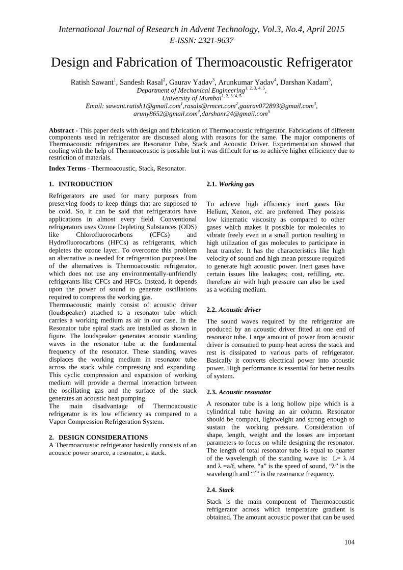
3.3. Stack
The material selected for stack is Mylar whose thermal conductivity is 0.16w/mk and heat capacity 1.25kJ/kgK. The spiral stack consists of a polyester Mylar sheet, wound around a PVC pipe having a diameter of 5 mm. The Mylar sheet has a thickness of 0.06 mm.
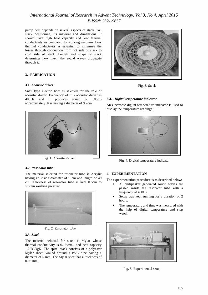
3.4. . Digital temperature indicator
An electronic digital temperature indicator is used to display the temperature readings.
4. EXPERIMENTATION
The experimentation procedure is as described below: • A loudspeaker generated sound waves are
passed inside the resonator tube with a frequency of 400Hz.
• Setup was kept running for a duration of 2 hours.
• The temperature and time was measured with the help of digital temperature and stop watch.
Fig. 1. Acoustic driver
Fig. 2. Resonator tube
Fig. 3. Stack
Fig. 4. Digital temperature indicator
Fig. 5. Experimental setup

International Journal of Research in Advent Technology, Vol.3, No.4, April 2015 E-ISSN: 2321-9637
106
5. APPLICATIONS
Low cost, high efficiency eco-friendly cooling devices such as Thermoacoustic have broad applications in households and commercial industries. Since most of the noise generating electronic components, e.g. semiconductor devices, operate faster and more effectively at lower temperatures. If Thermoacoustic could be employed in electronic industries then overall efficiency of electronic devices can be increased. Future applications of Thermoacoustic cooling devices would not be restricted to industrial uses only but also could provide inexpensive heating and cooling for homes.
6. CONCLUSION
In this paper design considerations for Thermoacoustic refrigerator are discussed. Appropriate parameters were selected and fabrication is done. Temperature variations across the stack were non determinant because of oscillations in the temperature of room and device. Our resonator was able to hold 1.5 atm without experiencing major leaks. Giving the Thermoacoustic refrigerator a higher pressure capacity would likely allow it to cool better. The efficiency of Thermoacoustic refrigerator can be improved by either and/or combining following ideas. • Changing the position of stack. • Using an inert gas as a medium. • Using an acoustic driver of a higher intensity. • One could use parallel plates instead of spiral
stack.
REFERENCES
[1] G.W. Swift,. Thermo acoustics: A unifying perspective for some engines and refrigerators., short course, March 1999 Berlin.
[2] G.W. Swift, .Thermoacoustic engines and refrigerators., Encyclopedia of Applied physics. 21, 245 (1997).
[3] T.J. Hofler, .Thermoacoustic refrigerator design and performance., Ph.D. dissertation, Physics Department, University of California at San Diego, (1986).
[4] Tijani M.E.H., Zeegers J.C.H., and De Waele A.T.A.M. “Construction and performance of a thermoacoustic refrigerator.” Cryogenics, 42(1):59-66, 2001.
[5] Garett, S. L. (2004). Resource letter: TA-1: Thermoacoustic engines and refrigerators.
[6] Viswa Mohan Pedagopu & Khannaji Pattapu, “A novel approach to design and fabrication of thermo-acoustic refrigerator using high amplitude sound waves”, IOSR Journal of Mechanical and Civil Engineering (IOSR-JMCE) e-ISSN: 2278-1684,p-ISSN: 2320-334X, Volume 8, Issue 6 (Sep. - Oct. 2013), PP 15-24.
[7] İbrahim GİRGİN , Mehmet TÜRKER, “Thermoacoustic Systems As An Alternative To Conventional Coolers” , Journal of Naval Science and Engineering 2012, Vol.8, No.1, pp.14-32.
[8] Scott Backhaus and Greg Swift, “New Varieties Of Thermoacoustic Engines”, LA-UR-02-2721, 9th International Congress on Sound and Vibration, July 2002.
[9] C. Herman, Z. Travnicek. Cool sound: the future of refrigeration? Thermodynamic and heat transfer issues in thermoacoustic refrigeration. Heat and Mass Transfer. April 2006.
[10] Daniel A. Russell and Pontus Weibull, "Tabletop thermoacoustic refrigerator for demonstrations," Am. J. Phys. 70 (12), December 2002.