design and evaluation of a hierarchical on-chip
TRANSCRIPT

Design and Evaluation of a Hierarchical On-Chip Interconnectfor Next-Generation CMPs
Reetuparna Das, Soumya Eachempati, Asit K. Mishra, Vijaykrishnan Narayanan, Chita R. Das
Department of Computer Science and Engineering,
The Pennsylvania State University, University Park, PA 16801
{rdas,eachempa,amishra,vijay,das}@cse.psu.edu
Abstract
Performance and power consumption of an on-chip interconnectthat forms the backbone of Chip Multiprocessors (CMPs), are di-rectly influenced by the underlying network topology. Both theseparameters can also be optimized by application induced commu-nication locality since applications mapped on a large CMP systemwill benefit from clustered communication, where data is placed incache banks closer to the cores accessing it. Thus, in this paper,we design a hierarchical network topology that takes advantageof such communication locality. The two-tier hierarchical topologyconsists of local networks that are connected via a global network.The local network is a simple, high-bandwidth, low-power sharedbus fabric, and the global network is a low-radix mesh. The key in-sight that enables the hybrid topology is that most communicationin CMP applications can be limited to the local network, and thus,using a fast, low-power bus to handle local communication will im-prove both packet latency and power-efficiency. The proposed hier-archical topology provides up to 63% reduction in energy-delay-product over mesh, 47% over flattened butterfly, and 33% with re-spect to concentrated mesh across network sizes with uniform andnon-uniform synthetic traffic. For real parallel workloads, the hy-brid topology provides up to 14% improvement in system perfor-mance (IPC) and in terms of energy-delay-product, improvementsof 70%, 22%, 30% over the mesh, flattened butterfly, and concen-trated mesh, respectively, for a 32-way CMP.
Although the hybrid topology scales in a power- and bandwidth-efficient manner with network size, while keeping the averagepacket latency low in comparison to high radix topologies, ithas lower throughput due to high concentration. To improve thethroughput of the hybrid topology, we propose a novel router micro-architecture, called XShare, which exploits data value locality andbimodal traffic characteristics of CMP applications to transfermultiple small flits over a single channel. This helps in enhancingthe network throughput by 35%, providing a latency reduction of14% with synthetic traffic, and improving IPC on an average 4%with application workloads.
1. Introduction
Performance of future many core/CMP systems with 10’s to 100’sof cores will heavily depend on the underlying on-chip intercon-nects, also known as Network-on-Chip (NoC) architectures, for fa-cilitating scalable communication between cores, caches and mem-ories. To minimize the communication cost, these systems shouldbe designed such that data accessed by threads will be allocated tocache banks or memories closer to the processing core a thread isrunning on. Researchers have proposed several hardware [1, 2, 3]and software mechanisms [4] to enforce such communication local-ity in CMPs. An oblivious design that does not optimize data place-ment to improve communication locality (and hence reduce com-
munication cost) will most likely have poor performance. Hence,an on-chip interconnect design that is cognizant of communicationlocality is likely to provide better and scalable performance than atraditional orthogonal design style.
In addition, power is no longer an after-thought, secondary met-ric in designing computer architectures. Along with high perfor-mance, low-power/energy-efficiency has become another criticalparameter in guiding architecture design and operation. It is pro-jected that an on-chip network power can become a substantial partof an entire chip power by consuming up to 40-60 watts [5] withtechnology scaling, if we do not design the interconnect carefully.Hence, a low power enabling solution is imperative for mediumto large scale on-chip interconnects. Thus, this paper presents anexercise of such a design trade-off study for NoCs, specifically fo-cusing on two key principles - communication locality and powerefficiency.
Network topology is a vital aspect of on-chip network de-sign since it determines several power-performance metrics. Itdetermines zero-load latency, bisection bandwidth, router micro-architecture, routing complexity, channel lengths, overall networkpower consumption, etc. Prior research has used a variety of in-terconnects such as shared bus [6], ring [7] and mesh/tori. The2D mesh topologies [8, 9, 10] have been popular for tiled CMPsbecause of their low complexity and planar 2D-layout properties.Recently, [11, 12] have proposed high radix topologies to minimizehop count, and thus, increase performance.
While mesh on one extreme, scales poorly in terms of perfor-mance and energy as a result of increased number of routers andaverage hop count, high radix topologies on the other hand, reducethe number of hops and routers at the cost of increased per routercomplexity and possibly energy consumption. The shared bus orring networks, on the contrary, are simple and power efficient, butdo not scale for larger configurations. While most of the prior NoCresearch have primarily focused on performance and/or energy ef-ficiency with little emphasis on workload characteristics, this paperattempts to optimize these parameters by leveraging the communi-cation locality. Thus, our design is centered around a two-tier hier-
archical1 topology to exploit the communication locality present inapplications.
The hierarchical network uses a high bandwidth shared busfor the first level local communication and a 2D mesh networkfor the global communication. The motivation for using these twowell known topologies is also driven by practicality in additionto performance and energy optimizations. Since bus-based designshave been well architected for small (4-8 node) CMPs, we believea bus-based local network is an ideal candidate to support the localcommunication. Similarly, we believe the planar, low complexitymesh topology seems a practical choice for the global network.
1 We use the terms hierarchical and hybrid interchangeably in this paper.
175978-1-4244-2932-5/08/$25.00 ©2008 IEEE

We further enhance this topology through a novel router micro-architecture, called XShare, which exploits bi-modal traffic anddata value locality of applications to transfer multiple smallerflits over a channel. We comprehensively evaluate four topologies(mesh, concentrated mesh, flattened butterfly and our hierarchi-cal design) across different network sizes (16 nodes to 256 nodesbased on technology scaling) using both synthetic and applicationworkloads. For the synthetic workload, we use both uniform andnonuniform traffic patterns to examine how the performance (aver-age network latency), power, and energy-delay product changes asa network experiences communication locality.
Overall, the major contributions of this paper are:
• We design a low complexity, power-efficient, hierarchicaltopology, which is a hybrid of two simple networks, and is op-timized for locality in communication. We quantitatively showthat such a hierarchical topology can provide on an average anenergy delay product gain of 63% over the mesh, 47% overthe flattened butterfly, and 33% over the concentrated meshfor uniform and non-uniform traffic patterns and all networksizes. With application workloads and a simple locality awaredata mapping policy for a 32-way CMP (64 nodes), the hybridtopology improves system performance (IPC) on an average by14% over the mesh.
• We propose an optimization, called XShare, to increase theconcurrency and throughput of the hybrid topology. XShareallows multiple small flits (control packets and value data flits)to be transferred over a single channel. XShare can furtherimprove the latency of hybrid topology by 14% for uniformrandom traffic and shifts the saturation throughput by 35%. TheIPC gain obtained using this technique is 4%.
The remainder of this paper is organized as follows: In Sec-tion 2, we summarize different topologies and their initial powercharacteristics. This is followed by detailed design of the proposedthe hybrid architecture in Section 3. Section 4 describes the simu-lation infrastructure, followed by results in Section 5, related workin Section 6, and conclusions in Section 8.
2. Preliminaries and Motivation
2.1 Network Topologies
In a medium to large CMP system, an on-chip network needsto minimize the communication overhead for performance andpower scalability. This calls for a clustered communication ap-proach wherein most of the communication can be limited to smallset of nodes. With this motivation, in this paper we analyze variousdesign options using state-of-art network topologies and proposea hybrid topology that embraces the hierarchical communicationparadigm, while minimizing power consumption.
We analyze three topologies namely mesh, concentrated meshand flattened butterfly, to understand their impact on power andcommunication locality. Mesh has been the most popular topologyfor on-chip network so far [8, 9, 10]. This simple and regulartopology has a compact 2D layout. Mesh, however, is crippledby rapidly increasing diameter that degrades its performance andpower, yielding it unsuitable for larger networks. Researchers haveproposed two topologies that address this limitation - flattenedbutterfly [11] and concentrated meshes [12].
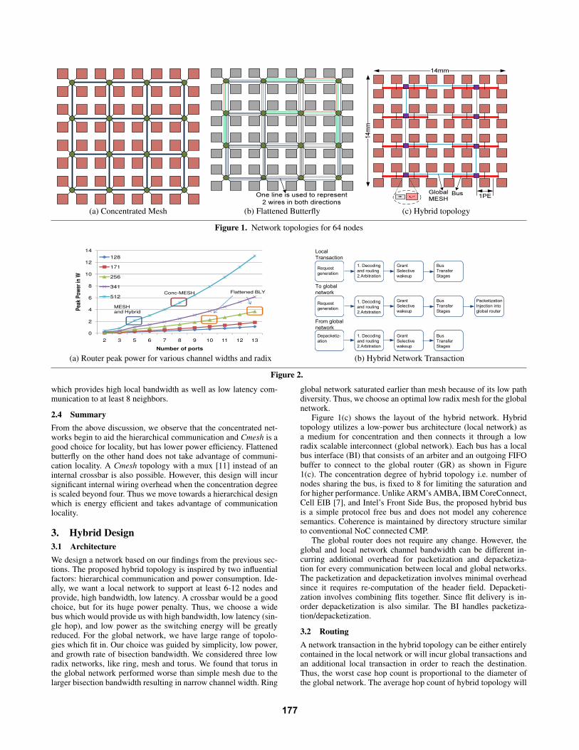
A concentrated mesh (Cmesh) preserves the advantages of amesh and works around the scalability problem by sharing therouter between multiple injecting nodes. The number of nodessharing a router is called the concentration degree of the network.Figure 1(a) shows the layout for Cmesh for 64 nodes. In [12], thisbasic design was enhanced by adding express channels betweenrouters on the perimeter or using two networks. Cmesh reduces the
number of routers resulting in reduced hop count and thus yieldingexcellent latency savings over mesh. Cmesh has a radix (numberof ports) of 8. It can also afford to have very wide channels (512+bits) due to a slowly growing bisection.
A flattened butterfly (fbfly) reduces the hop count by employ-ing both concentration as well as rich connectivity by using longerlinks to non-adjacent neighbors. The higher connectivity increasesthe bisection bandwidth and requires a larger number of ports inthe router. This increased bisection bandwidth results in narrowerchannels. Figure 1(b) shows a possible layout for a flattened but-terfly with 64 nodes. The rich connectivity trades off serializationlatency for reducing the hop count. Innovative solutions to adaptthe layout of flattened butterfly to a 2D-substrate were proposed in[11]. fbly has a radix between 7-13 depending on the network sizeand small channel widths (128+ bits).
2.2 Initial Power Analysis
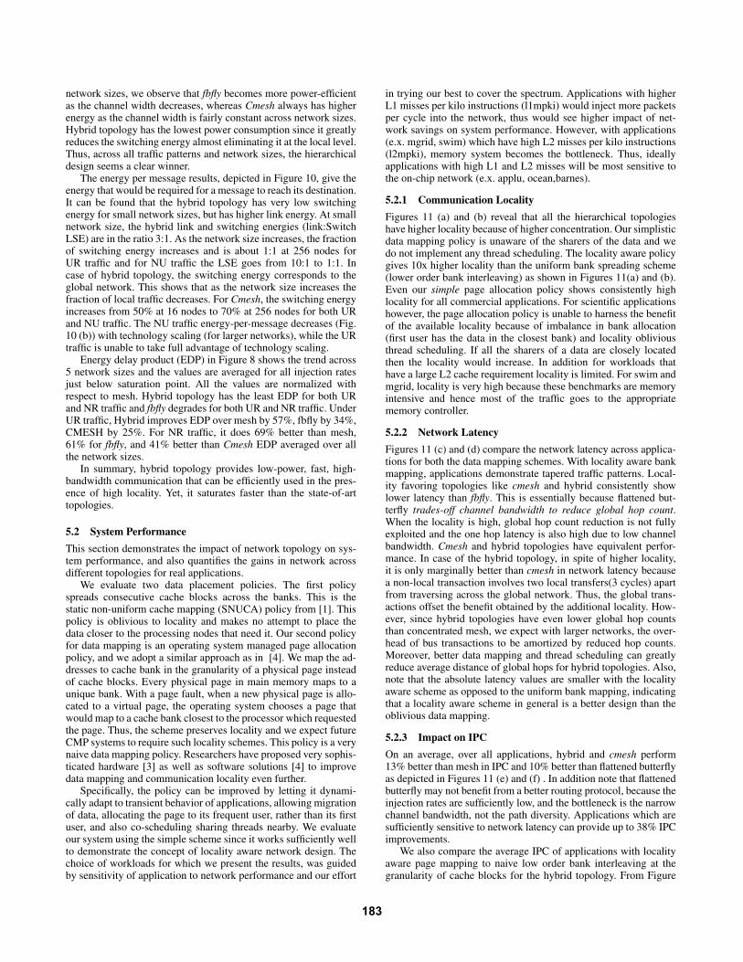
We conduct an initial power analysis of routers as a function ofradix and channel width. Figure 2(a) shows the design spectrum oftopologies with respect to per router power consumption at 2GHzand 35nm technology. Each point in this chart is a possible routerconfiguration dependant on its radix and channel width. Note that,the total network power also depends on the number of routers inthe network.
The router power grows with radix and channel width. Further,analyzing the breakup of the router power, we find that for a chan-nel width of 512 bits and for 5-ports, the fraction of crossbar poweris 83% of the total router power. We realize that crossbar is one themajor power hungry components in the router and the fraction ofcrossbar power increases as the radix increases.
Cmesh has both high radix as well as high channel width result-ing in high per router power. A Cmesh router, thus, consumes 2.5times more power than a mesh router. However, due to the lessernumber of routers, cmesh consumes lesser power than mesh. Yet,the high power consumption in Cmesh routers will limit how muchwe can increase the concentration and thus, how much we can re-duce the hop count via concentration. A flattened butterfly router isenergy-efficient. This is because the increase in radix of the routeris balanced by smaller channel width.
In summary, router power increases with both the channel widthand radix of the router. Switching power is a major portion of thetotal router power, thus we use a bus for local network. Both thehierarchical topologies and flattened butterfly, have better powerefficiency than a concentrated mesh and mesh.
2.3 Communication Locality
We define locality as the percentage of packets injected by a nodethat are satisfied by its immediate neighbors in the network. Ap-plications with high locality tend to have nearest neighbor commu-nication pattern with high local traffic. Hence, a network topologywhich can support high local bandwidth,and low latency local com-munication is cognizant of communication locality.
A mesh has narrow channels and hence low local bandwidth.Also, it has to pay at least one hop latency cost to reach out to4 neighbors. A concentrated mesh design is better for locality be-cause it has wide channels and hence high local bandwidth. Due toconcentration, Cmesh can provide low latency local communica-tion with c neighbors, with at least half the latency cost of a mesh,where c is the degree of concentration.
In contrast, flattened butterfly is not conducive for communi-cation locality. It has low local bandwidth due to narrow channels.Thus fbfly trades-off local bandwidth for reducing global hop count.A hierarchical design, however, takes complete advantage of com-munication locality. The local network is a wide, low latency bus
176
One line is used to represent 2 wires in both directions
14mm
14mm
1PE�� �� BusGlobalMESH
(a) Concentrated Mesh (b) Flattened Butterfly (c) Hybrid topology
Figure 1. Network topologies for 64 nodes
0
2
4
6
8
10
12
14
2 3 5 6 7 8 9 10 11 12 13
Pea
k P
ow
er in
W
Number of ports
128
171
256
341
512
MESH and Hybrid
Flattened BLYConc-MESH
(a) Router peak power for various channel widths and radix
Request
generation
1. Decoding
and routing
2.Arbitration
Grant
Selective
wakeup
Request
generation
Grant
Selective
wakeup
Bus
Transfer
Stages
Bus
Transfer
Stages
Packetization
Injection into
global router
Depacketiz-
ation
Grant
Selective
wakeup
Bus
Transfer
Stages
1. Decoding
and routing
2.Arbitration
1. Decoding
and routing
2.Arbitration
Local
Transaction
To global
network
From global
network
(b) Hybrid Network Transaction
Figure 2.
which provides high local bandwidth as well as low latency com-munication to at least 8 neighbors.
2.4 Summary
From the above discussion, we observe that the concentrated net-works begin to aid the hierarchical communication and Cmesh is agood choice for locality, but has lower power efficiency. Flattenedbutterfly on the other hand does not take advantage of communi-cation locality. A Cmesh topology with a mux [11] instead of aninternal crossbar is also possible. However, this design will incursignificant internal wiring overhead when the concentration degreeis scaled beyond four. Thus we move towards a hierarchical designwhich is energy efficient and takes advantage of communicationlocality.
3. Hybrid Design
3.1 Architecture
We design a network based on our findings from the previous sec-tions. The proposed hybrid topology is inspired by two influentialfactors: hierarchical communication and power consumption. Ide-ally, we want a local network to support at least 6-12 nodes andprovide, high bandwidth, low latency. A crossbar would be a goodchoice, but for its huge power penalty. Thus, we choose a widebus which would provide us with high bandwidth, low latency (sin-gle hop), and low power as the switching energy will be greatlyreduced. For the global network, we have large range of topolo-gies which fit in. Our choice was guided by simplicity, low power,and growth rate of bisection bandwidth. We considered three lowradix networks, like ring, mesh and torus. We found that torus inthe global network performed worse than simple mesh due to thelarger bisection bandwidth resulting in narrow channel width. Ring
global network saturated earlier than mesh because of its low pathdiversity. Thus, we choose an optimal low radix mesh for the globalnetwork.
Figure 1(c) shows the layout of the hybrid network. Hybridtopology utilizes a low-power bus architecture (local network) asa medium for concentration and then connects it through a lowradix scalable interconnect (global network). Each bus has a localbus interface (BI) that consists of an arbiter and an outgoing FIFObuffer to connect to the global router (GR) as shown in Figure1(c). The concentration degree of hybrid topology i.e. number ofnodes sharing the bus, is fixed to 8 for limiting the saturation andfor higher performance. Unlike ARM’s AMBA, IBM CoreConnect,Cell EIB [7], and Intel’s Front Side Bus, the proposed hybrid busis a simple protocol free bus and does not model any coherencesemantics. Coherence is maintained by directory structure similarto conventional NoC connected CMP.
The global router does not require any change. However, theglobal and local network channel bandwidth can be different in-curring additional overhead for packetization and depacketiza-tion for every communication between local and global networks.The packetization and depacketization involves minimal overheadsince it requires re-computation of the header field. Depacketi-zation involves combining flits together. Since flit delivery is in-order depacketization is also similar. The BI handles packetiza-tion/depacketization.
3.2 Routing
A network transaction in the hybrid topology can be either entirelycontained in the local network or will incur global transactions andan additional local transaction in order to reach the destination.Thus, the worst case hop count is proportional to the diameter ofthe global network. The average hop count of hybrid topology will
177

be half that of a concentrated mesh, because of higher concentrationdegree (8 for hybrid and 4 for cmesh).
Figure 2(b) shows how transactions are handled in the hybridnetwork. As shown, a bus transaction has two stages in addition tothe actual bus transfer latency and each stage takes one clock cycle.For the global network, we use dimension order routing.
3.3 XShare Channel Sharing
The on chip network is used to transfer various classes of traffic, in-cluding data packets and control packets. Data packets are typicallylarge in size (512-1024 bits) and require a large channel width forlow network transfer latency. On the other hand, control packets areusually 36-64 bits and do not need such a large channel width. Re-cent research [13, 14] has demonstrated that even many of the dataflits (up to 60% of CMP Cache Data from real workloads) have fre-quent patterns such as all zeros or all ones. Thus, these data flits canalso be encoded in small number of bits (16-32 bits). We define anyflit which after encoding or originally uses at most half the chan-nel width as a short flit. Existing NoCs implement channels withrelatively large width (128-256 bits) to reduce the serialization la-tency for larger packets. This results in internal fragmentation andreduced link utilization when a short flit is transferred since a largeportion of the channel width is not used.
To reduce internal fragmentation in channels and to improvelink utilization, we propose the XShare mechanism. XShare allowsmultiple short flits to be transferred over a single, wider channel.Figure 3(a) shows a generic crossbar for a mesh topology, wherethe input ports from the four cardinal directions and from the localPE (North:Nin, South:Sin, East:Ein, West:Win, Injection:PEin)are mapped to the output ports (North:Nout, South:Sout, East:Eout,West:Wout, Ejection:PEout). However, one output port may bemapped to only one of the input ports at any time (Ein mappedto Sout in Figure 3 (a)). This allows a single flit to traverse thecrossbar out to a particular output port(Sout), blocking all otherinput ports. Figure 3 (b) shows the XShare crossbar, where thecrossbar is broken into two logical data sets, thus two input ports(Nin and Ein in Figure 3 (b)) can be mapped to a single output port.Therefore, if two short flits want to go to the same output port theycan both simultaneously traverse the crossbar and subsequently thelink to reach the next router. A low overhead zero-one detector canbe used to identify short flits at injection.
Ein Sout (1:1 full mapping)
Nin
Ein
Sin
Win
PEoutNoutEoutSoutWout
PEin
Nin
Ein
Sin
Win
PEoutNoutEoutSoutWout
Nin (half) +Ein (half) Sout2:1 partial mapping
PEin
(a) Full (b) Partial
Figure 3. Baseline and XShare Crossbar Mapping
3.4 XShare Input Buffer Logic
To support the combination of shorter flits, few modules of therouter needs to be re-engineered. Figure 4 shows the input bufferlogic modifications (W is the width of the channel). Essentially,the data path of the input DEMUX and the switch MUX is splitinto two separable halves. The incoming combined flit has twovirtual channel ids (VCIDs) in its header and it is demuxed basedon the VCIDs into two separate virtual channels. Similarly a switchallocation (SA) control logic now sends two demux signals that
WW
:
:
:
:
:
:
:
:
DSET2DSET1
W/2
W
W/2
W
W/2
VCID1
VCID2
(a) Baseline (b) XShare
Figure 4. Baseline and XShare input buffers
determine which half of the crossbar a flit needs to be routed(Upper Half is Data Set1 (DSET1) and Lower Half is Data Set2(DSET2)). The buffer can still be maintained as a FIFO bufferwith no changes. They are treated as two separate logical halves(DSET’s) by the MUX/DEMUX logic. The main overhead comesfrom including the second layer of smaller muxes (color codedpurple in the figure). The buffer read / buffer write stages are theshortest stages in a generic router pipeline, and have sufficient slackfor 2:1 muxes.
3.5 XShare Switch Arbitration Logic
Figure 5 (a) shows the switch arbitration (SA) stage of a typical on-chip router. The SA stage can be broken into two stages. In the firststage, (SA stage 1) a v:1 arbiter for each input port chooses whichof its virtual channels (vi) can bid for the output port. In the secondstage, (SA stage 2) a p:1 arbiter for each output port (po) choosesone of the input ports(pi). Thus, at the end of the SA stage, a (pi,vi) pair is chosen for each output port po and a crossbar is mappingis enabled between pi and po.
Short flits can be combined by XShare in two cases.
• If any two input virtual channels(VCs) within a single input portrequest the same output port,and each has a short flit, then theycan be combined. A combined request for both these VCs canbe sent to SA stage 1. If the combined request wins SA stage 2,both the short flits can be sent together.
• If there are two input VCs, each with a short flit, but fromdifferent input ports requesting for the same output port, theycan be combined in SA stage 2.
The complexity of XShare can be attributed to selecting the secondflit in SA stage. This can be done in three ways as shown in Fig-ure 5. We chose the design shown in Figure 5(c) for evaluations.Inthis design there are two simultaneous p:1 arbiters. Only short flitrequests are sent to the second p:1 arbiter. In case the top arbiterpicks a short flit, the second arbiter will supply a matching shortflit. The probability that both arbiters will pick the same flit is verylow. The area overhead of XShare is primarily due to extra arbitersand is around 3% of router area obtained from Synopsys synthesisat 90nm.
Although XShare can be applied as a generic technique to anytopology, it is better suited for the hybrid topology because: (1)In hybrid topology, any two short flits requesting for the sharedbus can always be combined; (2) The complexity of the additionalXShare arbitration logic is O(p), where p is radix of the router.Thus, a low radix router like a hybrid global interconnect (p=5) ismore suitable than routers with high radix routers; (3) Also, lowerthe number of ports, higher is the probability of finding flits that canbe combined, because most flits would need to go to the same out-put port. (4) Finally, XShare is primarily a throughput improvementmechanism, and hence more suitable for hybrid topology whichsaturates earlier due to high concentration.
178

2nd stage arbiters
1st stage arbiters
Inp. Port 1
Inp. Port P
Out. Port 1
Out. Port P
One v:1
Arbiter per
Input Port
(Total of P v:1
Arbiters)
Two P/2:1
Arbiter per
Output Port
(Total of 2P P/
2:1 Arbiters)
2nd stage arbiters
1st stage arbiters
Inp. Port 1
Inp. Port P
Out. Port 1
Out. Port P
One v:1 Arbiter
per Input Port
(Total of P v:1
Arbiters)
Two P:1 Arbiter in
Parallel per Output Port
(Total of 2P P:1
Arbiters)
2nd stage arbiters
1st stage arbiters
Inp. Port 1
Inp. Port P
Out. Port 1
Out. Port P
One v:1 Arbiter
per Input Port
(Total of P v:1
Arbiters)
Two P:1 Arbiter in
Series per Output
Port
(Total of 2P P:1
Arbiters)
Inverted Signals2 x 1 MUX
1st stage arbiters 2
nd stage arbiters
One v:1
Arbiter per
Input Port
(Total of P v:1
Arbiters)
One P:1 Arbiter
per Output Port
(Total of P P:1
Arbiters)
Inp. Port 1
Inp. Port P
Out. Port 1
Out. Port P
(a) (b) (c) (d)
Figure 5. Design options for XShare SA Stage (a) Baseline arbiters (b) Each p:1 arbiter broken into smaller p/2:1 arbiters (c) Twosimultaneous p:1 arbiters (d) Two back to back p:1 arbiters
4. Experimental Platform
4.1 Technology Assumptions
We explore the design space over a period of the 10 years startingfrom 70nm (2007) technology (corresponds to 16-node NoC) downto 18nm (2018) technology node (corresponds to 256-node NoC).We assume a 14mmx14mm die size, which remains constant acrosstechnologies and network node size of 3.5mm (CPU or cache)at 70nm that scales down by a factor of 0.7 for each technologygeneration. The wire parameters for global layers are obtained fromPTM [15] and we assume 1 metal layer to be dedicated for thenetwork. (Wire width at 70nm is 450nm). Assuming cores occupyhalf the chip area [5] and the cores use all the available metal layers,we use a conservative estimate of 4096 horizontal tracks per die at70nm. The number of wires increases by 30% due to wire-widthscaling with each technology generation. For a given topology,channel width is calculated from the bisection bandwidth and totalnumber of wires that is fixed across all four topologies. These arepresented in Figure 6 (a) for different technologies/networks.
The delay and power model of CACTI 6.0 [16] is used forestimating the values for link and the bus. Table 3 gives our as-sumptions of lengths and the values of dynamic energy and leak-age power for bus and the links. The delay and power model ofbus include the higher loading due to senders and receivers. Theadditional overhead of dedicated point-to-point links required forrequest and grant lines for the bus have also been modeled. Boththe network and cores run at a frequency of 2GHz. We used Orionpower model for estimating the router power[17].
4.2 Simulation Setup
The detailed configuration of our baseline simulation set-up isgiven in Table 1. Each terminal node in the network consists ofeither a core or a L2 cache bank. We implemented a detailedfull-system cycle-accurate hybrid NoC/ cache simulator for CMParchitectures with Simics as a front end. The memory hierarchyimplemented is governed by a two-level directory cache coherenceprotocol. Each core has a private write-back L1 cache. The L2cache is shared among all cores and split into banks. Our coherencemodel includes a MESI-based protocol with distributed directories,with each L2 bank maintaining its own local directory. The networkconnects the cores to L2 cache banks and to the on-chip memorycontrollers(MC) (Figure 6 (b)).
For the interconnects, we implemented a state of art low-latencypacket-based NoC router architecture. The NoC router adopts thedeterministic X-Y routing algorithm, finite input buffering, andwormhole switching and virtual channel flow control. We also
SPLASH 2: Is a suite of parallel scientific workloads. Eachbenchmark executed one threads per processor.
SPEComp: We use SPEomp2001 as another representativeworkload. The results of applu, mgrid and swim are presented.
Commercial Applications. (1) TPC-C, a database benchmarkfor online transaction processing (OLTP), (2) SAP, a sales anddistribution benchmark, and (3) SJBB and (4) SJAS, two Java-based server benchmarks. The traces were collected from mul-tiprocessor server configurations at Intel Corporation.
Table 2. Application workloads
model the detail artifacts of specific topologies that can lead toincreased pipeline stages in link traversal. The parameter we useacross different topologies are given in Figure 6 (a).
For the performance analysis, we use synthetic and a diverse setof application workloads comprising of scientific and commercialapplications. We run each application for at least one billion in-structions. The commercial applications are run for at least 10000transactions. The workload details are summarized in Table 2.
Parameters Bus
70nm 50nm 35nm 25nm 18nm
Length (mm) 7 4.9 3.43 2.4 1.68
Delay (ps) 498.9 442.9 353.9 247.7 173.4
Energy (pJ) 1.4 0.67 0.28 0.20 0.14
Leakage (nW) 23.5 13.3 3.5 2.4 1.7
Link
70nm 50nm 35nm 25nm 18nm
Length (mm) 3.5 2.45 1.7 1.2 0.84
Delay (ps) 233 208.8 167.5 117.3 82.1
Energy (pJ) 0.6 0.29 0.12 0.08 0.06
Leakage (nW) 10.2 5.49 1.4 0.98 0.69
Table 3. Energy and delay of bus and inter-router links
5. Performance Evaluation
We measure average network latency, power, and energy-delayproduct for comparing the four networks (mesh, concentratedmesh, flattened butterfly, and our hierarchical topology) by varyingthe network size and workload. For the application workloads, wecompare the IPC for a 32-way CMP (Network size is 64).
5.1 Synthetic Traffic
In this section, we present the results for two synthetic traffic pat-terns, namely uniform random (UR) and non-uniform/localized
179

Processor Pipeline SPARC 2 GHz processor, two-way out of order, 64-entry instruction window
L1 Caches 64 KB per-core(private), 4-way set associative, 128B block size, 2-cycle latency, split I/D caches
L2 Caches 1MB banks,shared, 16-way set associative, 128B block size, 6-cycles latency, 32 MSHRs
Main Memory 4GB DRAM,up to 16 outstanding requests for each processor, 400 cycle access
Network Router 2-stage wormhole switched, virtual channel flow control, 1024 maximum packet size
Table 1. Baseline Processor, Cache, Memory and Router Configuration
Topology No. of Channel Conc. Radix VCs Buffer No. of Totalnodes Width Degree Depth Routers Wires
Mesh16 512 1 5 4 4 16 409664 512 1 4 4 4 64 8192256 512 1 4 4 4 256 16384
CMesh16 512 4 8 4 2 4 409664 512 4 8 4 2 16 8192256 512 4 8 4 2 64 16384
Fbfly16 512 4 7 2 8 4 409664 256 4 10 2 8 16 8192256 128 4 13 2 16 64 16384
Hyb16 512 8 3 4 8 2 204864 512 8 5 4 4 8 8192256 512 8 5 4 4 32 16384
C
P���� C C
PP
C C
PP
C C
P
C
P���� P PP P
��������P ����������������
C C C C C C C C
C C C C C C C C
C C C C C C C C
P P PP PP
P P PP PP
(a) Network parameters (b) Physical Layout
Figure 6. Network assumptions
traffic (NU), in Figure 7 . We expect applications to lie in be-tween these two synthetic traffic patterns. Although we have ex-perimented with several non-uniform traffic distributions, here weonly discuss results for traffic that consists of 75% local traffic,where the destination is one hop away from the source, and the rest25% traffic is uniformly distributed to the non-local nodes. Figure 7(a-f) shows the latency throughput curves versus per node injectionrate, for the two traffic patterns and various network sizes. Fromthe figure, it is clear that mesh provides the best throughput butthe highest end-to-end latency. As the network sizes increases, allthe topologies saturate earlier because of higher number of inject-ing nodes, leading to higher injection rate. Mesh always providesvery high throughput due to higher path diversity. All hierarchicaltopologies saturate earlier than Mesh because of higher pressure onthe smaller network.
Latency Analysis of Uniform Random:For the 16 node configuration, Cmesh and flattened butterfly
have the same channel bandwidth. As a result, flattened butterflyhas better latency than Cmesh, because of its rich connectivity anddestinations being only one hop away. Hybrid topology has thebest latency but the lowest throughput.The low latency of hybridtopology at 16 node is due to the high percentage of traffic beingconfined to a single bus (up to 50%) , which makes it highly latencyefficient.
At larger network sizes, flattened butterfly fbfly latency is domi-nated by the serialization cost and consequently has higher latency.The reason being that the bisection bandwidth of the flattened but-terfly grows rapidly due to the rich connectivity resulting in nar-rower channels. Hybrid topology and Cmesh perform in a similarfashion and better than the others for UR traffic.
Latency Analysis of Non-Uniform (75% local traffic): As de-picted in Figures 7(b), 7(d) and 7(f), the hierarchical topology bene-fits maximum from the NU traffic by exploiting the communicationlocality. Cmesh is a close competitor for NU traffic. As the networksize increases, fbfly performs worse than simple mesh in throughput
and latency. The reason being that the one hop latency of mesh issmaller than fbfly. The hierarchical element in fbfly offers no bene-fit because of the low channel bandwidth leading to higher one-hoplatency.
The saturation point for all topologies with NU traffic shiftstowards the higher-end compared to UR traffic by as much as50% for large network sizes. This reveals two interesting points.First, this shows that with high local traffic, hierarchical topologieslike cmesh and hybrid can offer higher throughput. Second, foruniform traffic, the the saturation bottleneck is the global network,not the bus/concentration since the local network could support aninjection load rate of up to 10% with NU traffic. Theoretically, thebus can take load up to 12.5% (1 packet every cycle for 8 injectingnodes). The main observations from these results are:
• The Hybrid topology provides a high-bandwidth, low-latencymedium which can be better exploited by local traffic. Althoughit saturates earlier than other topologies, it still can handle mostreal world workloads that typically have more locality than URand have less than 10% injection rate.
• Fbfly scalability is constrained by its narrow channel width.
• In the hierarchical topologies, the achieved throughput is pri-marily limited by the global network.
• Mesh provides the highest throughput, but at increased latency.However, it performs well with local traffic.
5.1.1 Power Analysis
Figure 9(a-f) provide the power plots for all network sizes andtraffic patterns. Mesh is obviously very power-inefficient at allnetwork sizes. The power consumption of mesh at 64 and 256nodes reaches as high as 100W, implying that it may not be aviable option for designing low-power, scalable NoCs. Both Cmeshand fbfly have higher power consumption than hybrid due to thehigh switching energy (high radix networks) at 16 nodes. At larger
180

0
5
10
15
20
25
30
35
40
0 0.05 0.1 0.15 0.2 0.25 0.3
Late
ncy
(cyc
les)
Injection Rate(packets/node/cycle)
mesh cmesh fbfly hyb
0
5
10
15
20
25
30
35
40
0 0.05 0.1 0.15 0.2 0.25 0.3
Late
ncy (
cycle
s)
Injection Rate(packets/node/cycle)
mesh cmesh fbfly hyb
(a) Latency for 16 nodes with Uniform Random Traffic (b) Latency for 16 nodes with Non Uniform (75% local) Traffic
0
10
20
30
40
50
60
0 0.03 0.06 0.09 0.12 0.15 0.18
Late
ncy
(cyc
les)
Injection Rate(packets/node/cycle)
mesh cmesh fbfly hyb
0
10
20
30
40
50
60
0 0.05 0.1 0.15 0.2 0.25 0.3
Late
ncy (
cycle
s)
Injection Rate(packets/node/cycle)
mesh cmesh fbfly hyb
(c) Latency for 64 nodes with Uniform Random Traffic (d) Latency for 64 nodes with Non Uniform (75% local) Traffic
0
10
20
30
40
50
60
70
80
90
0 0.02 0.04 0.06 0.08 0.1
Late
ncy
(cyc
les)
Injection Rate (packets /node/cycle)
mesh cmesh fbfly hyb
0
10
20
30
40
50
60
70
80
90
0 0.05 0.1 0.15 0.2 0.25 0.3
Late
ncy (
cycle
s)
Injection Rate (packets /node/cycle)
mesh cmesh fbfly hyb
(e) Latency for 256 nodes with Uniform Random Traffic (f) Latency for 256 nodes with Non Uniform (75% local) Traffic
Figure 7. Load-Latency curves for Synthetic Traffic
0
0.2
0.4
0.6
0.8
1
1.2
16(0.08) 32(0.06) 64(0.04) 128(0.04) 256(0.02)
Norm
aliz
ed E
nerg
y D
ela
y P
roduct
Network Size(Avg till Injection Rate)
mesh cmesh fbfly hyb
0
0.5
1
1.5
2
2.5
16(0.09) 32(0.09) 64(0.09) 128(0.06) 256(0.05)
Norm
aliz
ed E
nerg
y D
ela
y P
roduct
Network Size(Avg till Injection Rate)
mesh cmesh fbfly hyb
(a) Uniform Random Traffic (b) Non Uniform (75% local) Traffic
Figure 8. Energy delay product normalized to mesh topology for synthetic traffic
181

0
5
10
15
20
25
30
35
40
0 0.05 0.1 0.15 0.2 0.25 0.3
Pow
er
(watts)
Injection Rate(packets/node/cycle)
mesh cmesh fbfly hyb
0
5
10
15
20
25
0 0.05 0.1 0.15 0.2 0.25 0.3
Pow
er
(watt
s)
Injection Rate(packets/node/cycle)
mesh cmesh fbfly hyb
(a) Power for 16 nodes with Uniform Random Traffic (b) Power for 16 nodes with Non Uniform (75% local) Traffic
0
10
20
30
40
50
60
70
80
0 0.03 0.06 0.09 0.12 0.15 0.18
Pow
er
(watts)
Injection Rate(packets/node/cycle)
mesh cmesh fbfly hyb
0
10
20
30
40
50
60
70
80
0 0.05 0.1 0.15 0.2 0.25 0.3
Pow
er
(watt
s)
Injection Rate(packets/node/cycle)
mesh cmesh fbfly hyb
(c) Power for 64 nodes with Uniform Random Traffic (d) Power for 64 nodes Non Uniform (75% local) Traffic
0
15
30
45
60
75
90
105
120
0 0.02 0.04 0.06 0.08 0.1 0.12 0.14
Pow
er
(watts)
Injection Rate (packets /node/cycle)
mesh cmesh fbfly hyb
0
15
30
45
60
75
90
105
120
0 0.05 0.1 0.15 0.2 0.25 0.3
Pow
er
(watt
s)
Injection Rate (packets /node/cycle)
mesh cmesh fbfly hyb
(e) Power for 256 nodes with Uniform Random Traffic (f) Power for 256 nodes with Nearest Neighbor Traffic
Figure 9. Load-Power curves for Synthetic Traffic
0
1
2
3
4
5
mes
h
cmes
h
fbfly hyb
mes
h
cmes
h
fbfly hyb
mes
h
cmes
h
fbfly hyb
16 64 256
Ene
rgy
(nJ)
buffer+arbiter switch link
0
0.5
1
1.5
2
2.5
mes
h
cmes
h
fbfly
hyb
mes
h
cmes
h
fbfly
hyb
mes
h
cmes
h
fbfly
hyb
16 64 256
Ene
rgy
(nJ)
buffer+arbiter switch link
(a) Uniform Random Traffic (b) Non Uniform (75% local) Traffic
Figure 10. Energy per message for Synthetic Traffic182
network sizes, we observe that fbfly becomes more power-efficientas the channel width decreases, whereas Cmesh always has higherenergy as the channel width is fairly constant across network sizes.Hybrid topology has the lowest power consumption since it greatlyreduces the switching energy almost eliminating it at the local level.Thus, across all traffic patterns and network sizes, the hierarchicaldesign seems a clear winner.
The energy per message results, depicted in Figure 10, give theenergy that would be required for a message to reach its destination.It can be found that the hybrid topology has very low switchingenergy for small network sizes, but has higher link energy. At smallnetwork size, the hybrid link and switching energies (link:SwitchLSE) are in the ratio 3:1. As the network size increases, the fractionof switching energy increases and is about 1:1 at 256 nodes forUR traffic and for NU traffic the LSE goes from 10:1 to 1:1. Incase of hybrid topology, the switching energy corresponds to theglobal network. This shows that as the network size increases thefraction of local traffic decreases. For Cmesh, the switching energyincreases from 50% at 16 nodes to 70% at 256 nodes for both URand NU traffic. The NU traffic energy-per-message decreases (Fig.10 (b)) with technology scaling (for larger networks), while the URtraffic is unable to take full advantage of technology scaling.
Energy delay product (EDP) in Figure 8 shows the trend across5 network sizes and the values are averaged for all injection ratesjust below saturation point. All the values are normalized withrespect to mesh. Hybrid topology has the least EDP for both URand NR traffic and fbfly degrades for both UR and NR traffic. UnderUR traffic, Hybrid improves EDP over mesh by 57%, fbfly by 34%,CMESH by 25%. For NR traffic, it does 69% better than mesh,61% for fbfly, and 41% better than Cmesh EDP averaged over allthe network sizes.
In summary, hybrid topology provides low-power, fast, high-bandwidth communication that can be efficiently used in the pres-ence of high locality. Yet, it saturates faster than the state-of-arttopologies.
5.2 System Performance
This section demonstrates the impact of network topology on sys-tem performance, and also quantifies the gains in network acrossdifferent topologies for real applications.
We evaluate two data placement policies. The first policyspreads consecutive cache blocks across the banks. This is thestatic non-uniform cache mapping (SNUCA) policy from [1]. Thispolicy is oblivious to locality and makes no attempt to place thedata closer to the processing nodes that need it. Our second policyfor data mapping is an operating system managed page allocationpolicy, and we adopt a similar approach as in [4]. We map the ad-dresses to cache bank in the granularity of a physical page insteadof cache blocks. Every physical page in main memory maps to aunique bank. With a page fault, when a new physical page is allo-cated to a virtual page, the operating system chooses a page thatwould map to a cache bank closest to the processor which requestedthe page. Thus, the scheme preserves locality and we expect futureCMP systems to require such locality schemes. This policy is a verynaive data mapping policy. Researchers have proposed very sophis-ticated hardware [3] as well as software solutions [4] to improvedata mapping and communication locality even further.
Specifically, the policy can be improved by letting it dynami-cally adapt to transient behavior of applications, allowing migrationof data, allocating the page to its frequent user, rather than its firstuser, and also co-scheduling sharing threads nearby. We evaluateour system using the simple scheme since it works sufficiently wellto demonstrate the concept of locality aware network design. Thechoice of workloads for which we present the results, was guidedby sensitivity of application to network performance and our effort
in trying our best to cover the spectrum. Applications with higherL1 misses per kilo instructions (l1mpki) would inject more packetsper cycle into the network, thus would see higher impact of net-work savings on system performance. However, with applications(e.x. mgrid, swim) which have high L2 misses per kilo instructions(l2mpki), memory system becomes the bottleneck. Thus, ideallyapplications with high L1 and L2 misses will be most sensitive tothe on-chip network (e.x. applu, ocean,barnes).
5.2.1 Communication Locality
Figures 11 (a) and (b) reveal that all the hierarchical topologieshave higher locality because of higher concentration. Our simplisticdata mapping policy is unaware of the sharers of the data and wedo not implement any thread scheduling. The locality aware policygives 10x higher locality than the uniform bank spreading scheme(lower order bank interleaving) as shown in Figures 11(a) and (b).Even our simple page allocation policy shows consistently highlocality for all commercial applications. For scientific applicationshowever, the page allocation policy is unable to harness the benefitof the available locality because of imbalance in bank allocation(first user has the data in the closest bank) and locality obliviousthread scheduling. If all the sharers of a data are closely locatedthen the locality would increase. In addition for workloads thathave a large L2 cache requirement locality is limited. For swim andmgrid, locality is very high because these benchmarks are memoryintensive and hence most of the traffic goes to the appropriatememory controller.
5.2.2 Network Latency
Figures 11 (c) and (d) compare the network latency across applica-tions for both the data mapping schemes. With locality aware bankmapping, applications demonstrate tapered traffic patterns. Local-ity favoring topologies like cmesh and hybrid consistently showlower latency than fbfly. This is essentially because flattened but-terfly trades-off channel bandwidth to reduce global hop count.When the locality is high, global hop count reduction is not fullyexploited and the one hop latency is also high due to low channelbandwidth. Cmesh and hybrid topologies have equivalent perfor-mance. In case of the hybrid topology, in spite of higher locality,it is only marginally better than cmesh in network latency becausea non-local transaction involves two local transfers(3 cycles) apartfrom traversing across the global network. Thus, the global trans-actions offset the benefit obtained by the additional locality. How-ever, since hybrid topologies have even lower global hop countsthan concentrated mesh, we expect with larger networks, the over-head of bus transactions to be amortized by reduced hop counts.Moreover, better data mapping and thread scheduling can greatlyreduce average distance of global hops for hybrid topologies. Also,note that the absolute latency values are smaller with the localityaware scheme as opposed to the uniform bank mapping, indicatingthat a locality aware scheme in general is a better design than theoblivious data mapping.
5.2.3 Impact on IPC
On an average, over all applications, hybrid and cmesh perform13% better than mesh in IPC and 10% better than flattened butterflyas depicted in Figures 11 (e) and (f) . In addition note that flattenedbutterfly may not benefit from a better routing protocol, because theinjection rates are sufficiently low, and the bottleneck is the narrowchannel bandwidth, not the path diversity. Applications which aresufficiently sensitive to network latency can provide up to 38% IPCimprovements.
We also compare the average IPC of applications with localityaware page mapping to naive low order bank interleaving at thegranularity of cache blocks for the hybrid topology. From Figure
183

0%
20%
40%
60%
80%
100%
120%
% p
acke
ts w
ith
in o
ne
ho
p
mesh cmesh fbfly hyb
0%
2%
4%
6%
8%
10%
12%
14%
% p
acke
ts w
ith
in o
ne
ho
p
mesh cmesh fbfly hyb
(a) Communication locality with locality aware mapping (b) Communication locality with uniform bank spreading
0
5
10
15
20
25
30
Late
ncy(c
ycle
s)
mesh cmesh fbfly hyb
0
5
10
15
20
25
30
Late
ncy(c
ycle
s)
mesh cmesh fbfly hyb
(c) Network latency with locality aware mapping (d) Network latency with uniform bank spreading
0.8
0.9
1
1.1
1.2
1.3
1.4
1.5
No
rma
lize
d IP
C
mesh cmesh fbfly hyb
0.8
0.9
1
1.1
1.2
1.3
1.4
1.5
No
rma
lize
d IP
C
mesh cmesh fbfly hyb
(e) System IPC with locality aware mapping (f) System IPC with uniform bank spreading
0
10
20
30
40
50
60
70
80
90
Energ
y D
ela
y P
roduct (n
J*c
ycle
s) mesh cmesh fbfly hyb
0
10
20
30
40
50
60
70
80
90
Energ
y D
ela
y P
roduct (n
J*c
ycle
s) mesh cmesh fbfly hyb
(g) Network edp with locality aware mapping (h) Network edp with uniform bank spreading
Figure 11. Application Results for 64 node CMP
184

0.8
0.9
1
1.1
1.2
1.3
1.4
1.5
No
rma
lize
d IP
C
uniform locality aware
Figure 12. IPC comparison of locality aware mapping with uni-form bank spreading mapping
12, it is clear that even a naive locality aware policy gives at least19% improvement over the lower order interleaving. This demon-strates that data mapping is an important factor and hardware-software co-designs can offer lucrative benefits.
5.2.4 Network energy delay product
Hybrid topologies consistently show lower energy-delay-product(edp) over all the other topologies for the locality aware mappingas shown in 11 (g). Overall, hybrid topology performs 30% betterin edp over cmesh and 22% better over fbfly. Flattened butterfly ismore energy efficient than cmesh because of narrower crossbars asseen earlier, and thus, has lower edp than cmesh inspite of havinghigher latency. Swim and mgrid have low edp than the othersbecause they are memory intensive and only those set of networkresources to reach the memory controllers are being used. In caseof ammp benchmark, the naive scheme results in imbalanced load(a few banks getting all the data and lot of sharers) and thus,negatively impacts its performance. Thus, a data-mapping schemeshould not only try to preserve locality, but also, should balanceload for enhanced performance. Also, note that the energy-delay-product is at least 2x smaller with the locality aware scheme thanthe uniform lower-order bank interleaving mapping, indicating thata locality aware scheme in general is a better design than obliviousdata mapping.
5.3 XShare Performance
In this section, we illustrate the benefits of using XShare archi-tecture. XShare can benefit from three traffic characteristics: (a)High percentile of short flits in CMP traffic; (b) Traffic patternswhich share common paths between source and destinations; Theresults are depicted in Figure 13 for a 64 node network Figure13 (a)
0
10
20
30
40
50
60
0 0.03 0.06 0.09 0.12 0.15
Late
ncy
(cyc
les)
Injection Rate(packets/node/cycle)
hyb hyb-xshare-50%
0.96
0.98
1
1.02
1.04
1.06
1.08
Norm
alized IP
C
hyb hyb-xshare
Figure 13. XShare (a) latency curve for UR traffic (b) IPC forapplications
shows the gain due to XShare with hybrid topology for uniformrandom traffic pattern with 50% short flits in the traffic. Initially,at low load, we see a marginal penalty due to XShare becauseof increased blocking. However, XShare shifts the saturation andimproves throughput by an order of magnitude. This is becauseXShare technique is able to multiplex the links simultaneouslywhen ever short flits occur in the traffic stream and hence, delivermore packets per cycle. Figure13 (b) shows that we gain on an aver-age 4.4% in IPC across applications with XShare over the baselinehybrid topology.
6. Related Work
This section summarizes the prior work on on-chip interconnecttopologies. For several decades, bus has been used as the mediumfor on-chip communication between shared memory and the pro-cessors. The main advantages a bus are easy of design, low powerconsumption and simpler coherence maintenance, since it aidssnooping. Kumar et al. [6] presented a comprehensive analysis ofinterconnection mechanisms for small scale CMPs. They evaluatea shared bus fabric, a cross bar interconnection, and point to pointlinks. Pinkston et al. [7] examined the cell broadband engine’sinterconnection network which utilizes two rings and one bus toconnect 12 core elements. These simple topologies are suitable forsmall scale systems and are not scalable for larger systems.
Recently, there has been a lot of research for building packet-switched networks using regular topology such as Mesh. Tile [18],a CMP built by Tilera company, uses five Meshes for connecting64 nodes. The Intel 80-core prototype also used a Mesh and foundthat the interconnection power can be as high as 50% of the chippower [9]. TRIPS [10] is another example that used Mesh for itsinterconnection network. Wang et al. [19] did a technology ori-ented, and energy aware topology exploration. They explored meshand torus interconnects with different degrees of connectivity forgeneralized on-chip Networks. It has been shown that mesh is notscalable for large systems, because of its rapid growing diameterresulting in large latency and high power consumption [12]. Bal-four and Dally [12] proposed using concentrated mesh topologiesand express channels (balanced meshes) for medium sized on chipnetworks. Kim et al. [11] propose a high radix flattened butterflytopology for on-chip networks to overcome the scalability limita-tions of a mesh.
Borkar [5] motivated the use of wide buses in conjunction withcircuit switched networks for power efficiency. Muralimanohar etal. [20], customized the interconnect for improving the NUCAcache access time using different metal layers for latency andbandwidth optimizations. A combination of bus and mesh wasused in the NUCA cache and evaluated for an 8-core CMP and anetwork size of up to 32 nodes. In [21], the authors have proposed ahybrid topology, where they have broken a larger mesh into smallersub-meshes and used a hierarchical ring as the global network.Their motivation was to decrease the global hop count and reducecongestion at the center of a large mesh.
Our work differs from all these prior works in that, we designa hybrid topology to suit the communication needs of applicationsrunning on CMP systems and evaluate its scalability, performanceand power behaviors across the forthcoming technology genera-tions for designing larger systems. We consider access patterns intypical CMPs to design the network and thereby provide latencyand power benefits.
7. Conclusions
The ubiquity of CMPs has marked a paradigm shift towardscommunication-centric design optimizations for performance andpower. In this context, NoCs are expected to play a major role in
185

optimizing the communication overheads, thereby improving per-formance and power savings of CMPs. One approach to minimizecommunication overhead is to exploit the communication localityof applications in designing the underlying interconnects. In thiswork, we attempt to exploit the communication locality by de-signing a two-tier hierarchical topology for facilitating local andglobal communication between cores. The hierarchical topologyconsists of a bus-based local network and a mesh-connected globalnetwork. We evaluate and compare the hybrid topology againstthree other state-of-art NoC topologies for various network sizesand workloads. Our simulation results indicate that the proposedhierarchical design can outperform the other networks in terms oflatency, power consumption and energy-delay product specificallywith localized communication.
On an average, the hybrid topology can give up to 63% im-provement over mesh, 33% over concentrated mesh and 47% overflattened butterfly, in energy delay product for synthetic traffic. Us-ing a locality aware data mapping policy for application workloads,we find that the hybrid topology can take more advantage of the lo-cality than other topologies. The proposed interconnect gives on anaverage 14% benefit in IPC and 70% reduction in energy-delay-product over a mesh for a 32-way (64-node) CMP. A limitation ofthe hierarchical NoC is that it saturates faster than the other designs,and in order to enhance the throughput, we propose a novel chan-nel sharing technique, called XShare, that can increase concurrency,and can provide up to 14% latency improvement and 35% higherthroughput for synthetic traffic. Also, traffic patterns with high lo-cality will push the saturation further. Even with its early saturation,the proposed hybrid topology can handle most of the applicationworkloads because of their low injection rates and communicationlocalities.
In conclusion, this paper makes a case for designing communi-cation locality aware hierarchical networks that can provide betterperformance and power consumption compared to other state-of-the-art high radix NoCs. We expect that by utilizing more intel-ligent schemes for preserving locality in large CMP systems, theperformance and power envelopes of a hybrid topology can be en-hanced further.
8. Acknowledgments
This work is supported in part by National Science Foundationgrants CCF-0702617 and CNS-0202007, funds from Intel Corpo-ration. The views expressed herein are not necessarily those of theNSF, Intel. We thank Ravi Iyer for commercial workload traces andSatish Narayanasamy for the initial suggestion of looking at appli-cation locality aware topologies. We also wish to thank Onur Mutlufor helpful comments and discussions.
References
[1] B. M. Beckmann and D. A. Wood, “Managing wire delay in largechip-multiprocessor caches,” in MICRO 37: Proceedings of the 37th
annual IEEE/ACM International Symposium on Microarchitecture,2004, pp. 319–330.
[2] Z. Chishti, M. D. Powell, and T. N. Vijaykumar, “Optimizingreplication, communication, and capacity allocation in cmps,”SIGARCH Comput. Archit. News, vol. 33, no. 2, pp. 357–368, 2005.
[3] J. Huh, C. Kim, H. Shafi, L. Zhang, D. Burger, and S. W. Keckler, “Anuca substrate for flexible cmp cache sharing,” in ICS ’05: Proceed-
ings of the 19th Annual International Conference on Supercomputing,2005, pp. 31–40.
[4] S. Cho and L. Jin, “Managing distributed, shared l2 caches throughos-level page allocation,” in MICRO 39: Proceedings of the 39th
Annual IEEE/ACM International Symposium on Microarchitecture.Washington, DC, USA: IEEE Computer Society, 2006, pp. 455–468.
[5] S. Borkar, “Networks for multi-core chips: A contrarian view,” inSpecial Session at ISLPED 2007.
[6] R. Kumar, V. Zyuban, and D. M. Tullsen, “Interconnections inmulti-core architectures: Understanding mechanisms, overheads andscaling,” SIGARCH Comput. Archit. News, vol. 33, no. 2, pp. 408–419,2005.
[7] T. W. Ainsworth and T. M. Pinkston, “Characterizing the cell eibon-chip network,” IEEE Micro, vol. 27, no. 5, pp. 6–14, 2007.
[8] M. B. Taylor, W. Lee, J. Miller et al., “Evaluation of the rawmicroprocessor: An exposed-wire-delay architecture for ilp andstreams,” in ISCA ’04: Proceedings of the 31st annual international
symposium on Computer architecture. Washington, DC, USA: IEEEComputer Society, 2004, p. 2.
[9] S. Vangal, J. Howard, G. Ruhl et al., “An 80-tile 1.28tflops network-on-chip in 65nm cmos,” in Solid-State Circuits Conference, 2007.
ISSCC 2007. Digest of Technical Papers. IEEE International, 11-15Feb. 2007, pp. 98–589.
[10] K. Sankaralingam, R. Nagarajan, R. McDonald et al., “Distributedmicroarchitectural protocols in the trips prototype processor,” inMICRO 39: Proceedings of the 39th Annual IEEE/ACM International
Symposium on Microarchitecture. Washington, DC, USA: IEEEComputer Society, 2006, pp. 480–491.
[11] J. Kim, J. Balfour, and W. Dally, “Flattened butterfly topology for on-chip networks,” Microarchitecture, 2007. MICRO 2007. 40th Annual
IEEE/ACM International Symposium on, pp. 172–182, Dec. 2007.
[12] J. Balfour and W. J. Dally, “Design tradeoffs for tiled cmp on-chipnetworks,” in ICS ’06: Proceedings of the 20th annual international
conference on Supercomputing. New York, NY, USA: ACM, 2006,pp. 187–198.
[13] R. Das, A. K. Mishra, C. Nicopoulos, D. Park, V. Narayanan, R. Iyer,and C. R. Das, “Performance and Power Optimization throughData Compression in Network-on-Chip Architectures,” in HPCA
’08: Proceedings of the 14th International Symposium on High
Performance Computer Architecture, 2008.
[14] D. Park, S. Eachempati, R. Das, A. K. Mishra, V. Narayanan,Y. Xie, and C. R. Das, “MIRA : A Multilayered InterconnectRouter Architecture,” in 35th International Symposium on Computer
Architecture (ISCA), 2008.
[15] W. Zhao and Y. Cao, “New generation of predictive technologymodel for sub-45nm design exploration,” in ISQED ’06: Proceedings
of the 7th International Symposium on Quality Electronic Design.Washington, DC, USA: IEEE Computer Society, 2006, pp. 585–590.
[16] N. Muralimanohar, R. Balasubramonian, and N. Jouppi, “Optimizingnuca organizations and wiring alternatives for large caches with cacti6.0,” Microarchitecture, 2007. MICRO 2007. 40th Annual IEEE/ACM
International Symposium on, pp. 3–14, 1-5 Dec. 2007.
[17] H. Wang, X. Zhu, L.-S. Peh, and S. Malik, “Orion: A Power-Performance Simulator for Interconnection Networks,” in ACM/IEEE
MICRO, Nov 2002.
[18] D. Wentzlaff, P. Griffin, H. Hoffmann et al., “On-chip interconnectionarchitecture of the tile processor,” IEEE Micro, 2007.
[19] H. Wang, L.-S. Peh, and S. Malik, “A technology-aware and energy-oriented topology exploration for on-chip networks,” in DATE ’05:
Proceedings of the conference on Design, Automation and Test in
Europe. Washington, DC, USA: IEEE Computer Society, 2005, pp.1238–1243.
[20] N. Muralimanohar and R. Balasubramonian, “Interconnect designconsiderations for large nuca caches,” ISCA ’07: Proceedings of the
34th Annual International Symposium on Computer Architecture, pp.369–380, 2007.
[21] S. Bourduas and Z. Zilic, “A hybrid ring/mesh interconnect fornetwork-on-chip using hierarchical rings for global routing,” in NOCS,2007, pp. 195–204.
186