design and development of low cost automatic parking ... · indian context no entry level cars like...
TRANSCRIPT

International Journal of Computer Applications (0975 – 8887)
International Conference on Information and Communication Technologies (ICICT-2014)
17
Design and Development of Low Cost Automatic Parking
Assistance System
Viswanath K. Reddy
ECE, Faculty of Engineering & Technology M.S. Ramaiah University of Applied Sciences
Bangalore-560058
Swaroop Laxmeshwar Student-FT10,
MS Ramaiah School of Advanced Studies Bangalore-560058
ABSTRACT
Parking cars is quite a challenge in congested parking bays
and for inexperienced drivers. Automatic parking assistance
systems (APAS) are limited to high-end cars in India. This
paper discusses the design of APAS for Hyundai Santro and
development of an automatic parking assistant system for a
scaled down prototype model using a stepper motor mounted
ultrasonic sensor to scan the obstacles. 3-point unequal
rotating radius algorithm is used to identify parking path
shifting points and parking trajectory. Path shifting control
algorithm based on timing and distance traversed is developed
using MPLAB IDE.
A prototype is developed on a scaled down model of a vehicle
and performance of the APAS system is verified. Accuracy of
the system is ±10% which is acceptable for low cost solution
developed. Repeatability of APAS is tested, which is ±15%.
This can be improved with closed loop control in parking
process. Cost of the developed system is reduced by more
than 50% of the commercially available APAS systems. From
the results, APAS system can be used in any small segment
cars with little changes in logic. Path traversed can be used as
feedback to further improve the accuracy of APAS system.
Keywords
Parking Assistance, Automatic, Intelligent, ECU, Three-point
Unequal Rotating Radius
1. INTRODUCTION In present day situation exploring the empty parking slot and
getting best maneuver while parking has become tedious
because of congested parking lots. Expert driver’s parking
skill is transferred to an intelligent system which can alleviate
the driving burden and enhance safety in the next generation
passenger vehicles [1]. Automatic Parking Assistance System
(APAS) comes to the rescue of inexperienced drivers to avoid
collision while reverse parking. An APAS is an emerging
standard safety feature in modern vehicles. The significance
of this system is to assist the driver to take ‘parking slot
fitment decision’ and also in ‘parking the vehicle’ once the
slot is confirmed. This system has the advantage of safety,
while parking in reverse direction by taking care of the blind
spots.
In APAS the parking slot availability is explored by the
system and then the parking is done on its own, thus
minimizing driver involvement. APAS operates in two phases
namely exploration and parking. In exploration phase, the
system evaluates the length and width of parking slot for
parking and confirms. In the parking phase the system guides
the vehicle to along a suitable trajectory and park in the
identified slot without collision. Various sensors like infrared
sensors, camera, ultrasonic sensors, RADAR etc are used to
observe the obstacles during parking.
In automatic parking systems radar, sonar, vision and
ultrasonic sensor are used in combination for obstacle
avoidance in parking trajectory. APAS systems are available
in various models from Toyota (Advanced Guided Parking
System), Lexus (Intuitive Parking Assist), and Volkswagen
(Park Assist) among others [2, 3]. The parking assist modules
in these cars cost in the range of 500$ to five thousand dollars
as per the data available in the open source websites. This
clearly indicates the expensive nature of the sensors and
algorithms built into the system and hence make it
unaffordable by the small segment Indian car owners. In the
Indian context no entry level cars like Maruti 800, Tata Nano,
and Hyundai Santro have APAS. Among various sensors used
for parking assistance, ultrasonic sensors are used as low cost
alternative for parking assistance [4]. Multiple ultrasound
sensors at fixed locations on the car are used for obstacle
detection purpose[5-6]. In this paper it is proposed to use a
stepper motor mounted single ultrasonic sensor for scanning
the obstacles for automatic parking assistant system and
develop a prototype of a scaled down model.
2. DESIGN OF APAS Figure 1 shows the parallel parking slot in which each vehicle
parks behind another vehicle which is assumed for the design.
Assumptions based on the minimum turning angle and
steering capabilities are made to choose the parking slot size.
Minimum margin while parking the vehicle from parking slot
corner points are made. These values are for actual vehicle
chosen (Hyundai Santro). For designing the parking path
knowledge of parking trajectory, final and corner points is
required. Pf (xf, yf) is the final point where the parking
process finishes, P1(x1, y1) is the starting point of parking
process and P0 (x0, y0) is corner point of the parking slot.
Parking slot dimensions are assumed to (6000, 3000), which
is average and sufficient parking space for most of the Indian
cars [2].
Fig. 1. Parking Slot Assumptions
APAS has sub-functions like gathering the driver inputs from
switches, reading the sensor data, checking the necessary
conditions, actuating the motors etc. The functional block
diagram of the system is developed and is shown in Figure 2.
Margin
P0(x0,y0)=(5000,5000)
6000mm
yd=3500mm
Pf(xf,yf)=(0,0)

International Journal of Computer Applications (0975 – 8887)
International Conference on Information and Communication Technologies (ICICT-2014)
18
Fig. 2. Functional Block Diagram of APAS
Driver warning block gives instructions and commands to the
driver, to take necessary actions, to make parking process
safer. LEDs, buzzers are to indicate the process status to the
driver. Sensor blocks are the major functional areas, which
helps the system to detect or sense the change in electrical or
physical parameters of that system. Sensor blocks collect the
sensor data and produce them in the readable format for
microcontroller. This makes the system to work as closed loop
and to add correction factors if there is an error inside the
system. Actuators like motors, electrical coils etc. are present
in this block. In micro controller block, the compatibility of
the controller the code required to run the application is
developed [3].
Parking paths are specific to vehicles and are designed based
on the vehicle dimensions, handling parameters and parking
limitations. In this work 3-point unequal rotating radius
method is used for generating the parking path for row
parking. Once the parking path is designed for that specific
vehicle, parking path shifting points are identified. This helps
the controller to take decision while parking the vehicle.
2.1 Propelling Motor Power Calculation Sum of all the individual powers required to overcome the
dynamic specifications like rolling resistance, acceleration
and aerodynamic resistances gives the total power required to
run the vehicle. Rolling resistance and aerodynamic
resistances are less or negligible compared with power
required to accelerate. Power required to propel the vehicle is
proportional to the maximum acceleration designed for that
vehicle. Different resistances offered to propel the vehicle are
shown in motor power calculation equation [7, 8].
𝑃𝑡 = 𝛿𝑀
2𝑡𝑎 𝑉𝑓
2 + 𝑉𝑏2 +
2
3 𝑀𝑔𝑓𝑟𝑉𝑓 +
1
5(𝜌𝑎𝐶𝐷𝐴)
2.1.1 Known Parameters: Mass of the vehicle, 𝑀 = 900𝑘𝑔
Air density, 𝜌𝑎 = 1.15 𝑘𝑔/𝑚3
Gravity, 𝑔 = 9.81 𝑚/𝑠2
2.1.2 Required Parameters: Acceleration time, 𝑡𝑎 = 2 𝑠 [Assumption] Final Velocity, 𝑉𝑓 = 2.7 𝑚/𝑠
Motor basic Velocity, 𝑉𝑏 = 1.85 𝑚 𝑠
2.1.3 Calculated Parameters: Aerodynamic Drag,𝐶𝐷 = 0.32 [Assumed from frontal area shape] Mass factor, 𝛿 = 1.05 Calculated for unknown δ Rolling Resistance, 𝑓𝑟 = 0.011 Frontal area, 𝐴𝑓 = 2.424 𝑚2
𝑃𝑡 = 2.691 𝑘𝑊
2.2 Calculation of Turning Radii (R1 &
R2) Based on the algorithm chosen, for ‘Hyundai Santro’
specifications parking path is generated. The specifications
are listed below and based on these values Final Turing
Radius (R1) while parking and First turning radius (R2) while
parking are calculated based on the algorithmic equations[9]
as shown in Figure 3.
Fig 3: Turning Radius R1 and R2
2.2.1 Parameters Required, Wheel Base 𝐿1 = 2380𝑚𝑚
Overall Width 𝑙 = 1525𝑚𝑚
Overall Length 𝐿 = 3565𝑚𝑚
Maximum Steering Angle, ∅𝑚𝑎𝑥 = 44.91°
Minimum Rotating Radius,
𝑅1 = 𝐿1 𝑡𝑎𝑛∅𝑚𝑎𝑥
𝑅1 = 2387𝑚𝑚 (𝐹𝑜𝑟 𝑐𝑖𝑟𝑐𝑙𝑒 𝑂1)
Parking Corner Safety Radius, 𝑅2 = 𝑙 2 + 𝑑
𝑅2 = 1262.5𝑚𝑚 (𝑆𝑎𝑓𝑒𝑡𝑦 𝑚𝑎𝑟𝑔𝑖𝑛, 500𝑚𝑚)
Based on the R1 and R2 values draw two circles on the graph
sheet to understand the ‘Parking Path’. ‘R1’ can be taken as
minimum turning radius of that vehicle, which gives the
shortest parking path. Minimum turning radius for Hyundai
Santro is 4.7m.
2.3 Specifications of Hyundai Santro To design path for the chosen vehicle the specifications are
collected from the manufacturer of that vehicle. Dimensions
of the vehicle, steering data for that vehicle and tire type,
specifications are collected and analyzed before starting the
design process. Those specifications are listed below.
2.3.1 Dimensions: Wheel Base 𝐿1 = 2380𝑚𝑚
Overall Width 𝑙 = 1525𝑚𝑚
Overall Length 𝐿 = 3565𝑚𝑚
Overall Height = 1590𝑚𝑚
Front Track = 1315𝑚𝑚
Rear Track = 1300𝑚𝑚
2.3.2 Steering Data: Minimum Turning Radius = 4.7m
Steering Wheel Rotation (Lock to Lock) = 4.3 rotations
2.3.3 Tire Type and Specifications: Tyre Type is P 155/70 R13”
Tyre Width = 163𝑚𝑚
Outer Diameter = 556𝑚𝑚
Rolling Circumference P = 1617𝑚𝑚
Rear Track = 1300𝑚𝑚
Effective Rolling Radius, 𝑅𝑑 = 266𝑚𝑚
International Journal of Computer Applications (0975 – 8887)
International Conference on Information and Communication Technologies (ICICT-2014)
19
Using ‘Pythagoras Theorem’, the shorter distance between
two points on the same circles are found. ‘AC’ is the shortest
distance and the angle is found out using the relation of sine
function.
𝑅 = 𝐴𝐵 = 𝐵𝐶 = 4.7𝑚
𝐴𝐶2 = 𝐴𝐵2 + 𝐵𝐶2
𝐴𝐶 = 6.66𝑚𝑚
Using definition,𝑠𝑖𝑛 𝜃 = 𝑂𝑝𝑝𝑜𝑠𝑖𝑡𝑒 𝑆𝑖𝑑𝑒 𝐻𝑦𝑝𝑜𝑡𝑒𝑛𝑖𝑢𝑠 ,
𝜃 = 𝑠𝑖𝑛−1(0.706)𝜃 = 44.91° (Max. turning angle at min. turning radius,∅𝑚𝑎𝑥 )
2.4 Calculation of Steering Angle at Initial
Position Calculations for steering angle at point P1 is shown here,
𝜃𝑡1 = 𝑐𝑜𝑠−1 0.8101 𝜃𝑡1 = 35.855°
Turning Angle of the vehicle at corner Point 𝑃0: (𝑥0 , 𝑦01)
is found here. Using this value ‘Parking path shifting points’
are calculated (like Point1, Point 2 etc.). To find path points,
the geometric values of a, b and 𝛼 values have to be
calculated first. For calculation purpose 𝑃0 (Corner point)
values are assumed. That is, 𝑃0 = (1500, 5000)
𝜃𝑡1 = 𝑐𝑜𝑠−1{1
𝑅1 − 𝑦0 2 + 𝑥0
2 [ 𝑅1 + 𝑅2 𝑅1 − 𝑦0
+ 𝑅1 + 𝑅2 2 𝑅1 − 𝑦0
2 − 𝛼]}
𝛼, 𝑎 𝑎𝑛𝑑 𝑏, are the design constants required to find
out the shifting points, the calculation as follows,
𝛼 = 𝑅1 − 𝑦0 2 + 𝑥0
2 { 𝑅1 + 𝑅2 2 − 𝑥0
2}
𝛼 = 2387 − 1500 2 + 50002 { 2387 + 1262.5 2
− 50002}
𝛼 = −30121910257657.75
Using the constant value, ‘a’ and ‘b’ values are calculated.
𝑎 = (𝑡𝑎𝑛 𝜃1)𝛼 = 0.723 ,
𝑏 = 𝑦0 + 𝑅2
𝑐𝑜𝑠 𝜃0= −557
2.5 Finding the Parking Path Points Initial point is the one from where the reverse parking process
is started. ‘P1’ describes the parking space required for that
system or vehicle.
𝑃1: (𝑥1 , 𝑦1)
𝑃1 = (𝑅1 (𝑎2 + 1) + 𝑦3 − 𝑏
𝑎 , 𝑦𝑑)
𝑃1: (6900 , 3500)
Here, 𝑃2 𝑜𝑟 𝑃3: (𝑥2 , 𝑦2)
𝑃2 = (𝑅1 𝑠𝑖𝑛 𝜃𝑡1 , 𝑅1(1 − 𝑐𝑜𝑠 𝜃𝑡1))
𝑃2 𝑜𝑟 𝑃3: (1399.13, 454)
These calculated values can be compared with the values after
the parking path graph is developed. If both calculated and the
graph values are within the design tolerance then these values
can be used as final points in parking process.
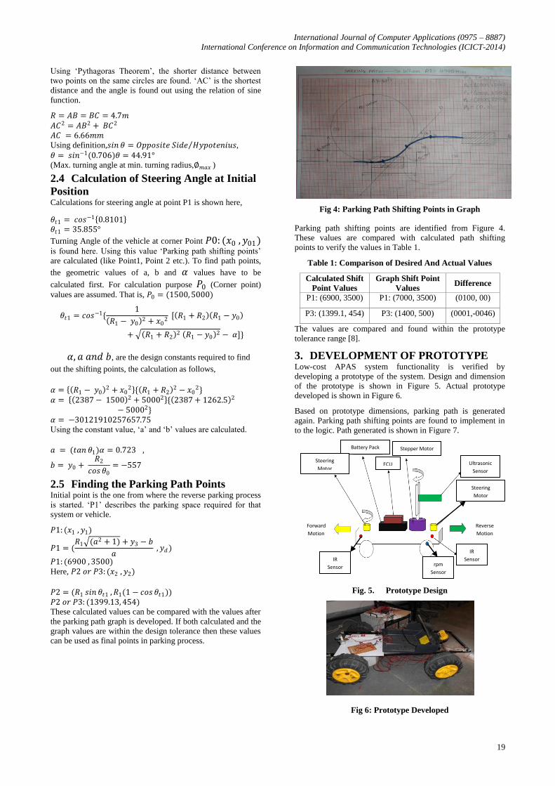
Fig 4: Parking Path Shifting Points in Graph
Parking path shifting points are identified from Figure 4.
These values are compared with calculated path shifting
points to verify the values in Table 1.
Table 1: Comparison of Desired And Actual Values
Calculated Shift
Point Values
Graph Shift Point
Values Difference
P1: (6900, 3500) P1: (7000, 3500) (0100, 00)
P3: (1399.1, 454) P3: (1400, 500) (0001,-0046)
The values are compared and found within the prototype
tolerance range [8].
3. DEVELOPMENT OF PROTOTYPE Low-cost APAS system functionality is verified by
developing a prototype of the system. Design and dimension
of the prototype is shown in Figure 5. Actual prototype
developed is shown in Figure 6.
Based on prototype dimensions, parking path is generated
again. Parking path shifting points are found to implement in
to the logic. Path generated is shown in Figure 7.
Fig. 5. Prototype Design
Fig 6: Prototype Developed
ECU
Stepper Motor Battery Pack
Ultrasonic
Sensor
rpm
Sensor
IR
Sensor IR
Sensor
Steering
Motor
Forward
Motion
Reverse
Motion
Steering
Motor

International Journal of Computer Applications (0975 – 8887)
International Conference on Information and Communication Technologies (ICICT-2014)
20
Table 2: Specifications of Prototype
Specifications Dimensions
Over all weight ~10kg
Overall Length 900mm
Overall width 570mm
Minimum Turning Radius 3.0m (Approx.)
Maximum steering angle ~25 degree (Approx.)
Assumed P0(x0, x0) (3000,1000) Parking slot
Margin (d) 200mm
Wheel radius (Rd) 105mm
Overall travelled distance (space searching function) is,
Distance = 4750mm, Rotations = 6.5, Time taken =12 to 14
sec, detailed breakup is shown in Table 3.
Table 3: Details of Distance Travelled
From – To
Shift Point Distance Rotations Time
P1 to P2 1750mm 2.5 5 sec
P2 to P3 1750mm 2.5 5 sec
P3 to Pf 1250mm 1.5 3 sec
Control logic is developed based on the parking pattern and
algorithm chosen. Parking path shifting points found from the
graph are coded to control the Parking process. Flow chart of
the control logic is shown in Figure 7.
Fig 7: Flow Diagram of APAS
Hardware is developed for APAS, Figure 8 shows hardware
schematic diagram. Figure 9 shows the prototype developed
for Low Cost APAS, with all the components assembled.
Ultrasonic sensor mounted on stepper motor to replace the
RADAR and IR sensor to confirm the parking space is shown
in Figure 9 and Figure 10.
Fig 8: PIC18F Interfacing with Peripherals
Fig 9: Low Cost APAS Prototype
4. RESULTS AND DISCUSSIONS Low-cost APAS system functionality is verified, with
different tests. Time taken to travel from one point to another
and distance traversed from one point to another are listed in
Table 4. Rotating radius of the prototype is deviating from the
desired values and making the system unstable. To achieve
better performance and high accuracy closed loop system can
be adopted in the same system. Table 3 shows the comparison
of desired values and actual values of APAS shift points.
Fig 10: Ultrasonic Sensor on Stepper Motor
The developed low-cost APAS is run on the floor to compare
the design specifications and actual parking path
specifications. Based on the demo vehicle specifications, the
code is developed and the specifications like parking path
shifting time, distances etc. are collected to compare with
given value. While implementing the ECU on vehicle the
parameters like approximate steering angle, distance to be
travelled while searching the parking slot are given. Before
testing the vehicle, fine tuning to match the actual path is
made. Correction values are noted and then the testing is
carried out. Figure 11 shows a test case for parking [10].
Ultrasonic
Sensor
Driver i/p
Switches IR Sensor
PIC 18F452
H-Bridge
Drive Motor
Stepper Motor
Steering Motor
IR Sensor

International Journal of Computer Applications (0975 – 8887)
International Conference on Information and Communication Technologies (ICICT-2014)
21
Table 4: Comparison of Desired and Actual Value
Parameters Desired value Actual
value
Time to reach
P1
10 to 12 sec 13 sec
Time P1 to P2 5.5 sec 6.0 sec
Time P2 to Pf 6.5 sec 7.0 sec
Min. Rotating
Radius
3000mm 4000mm
Steering Angle 25` Approx. < 25`
Approx
Distance P1 4250mm 4500mm
Distance P1 to
P2
2000mm 2250mm
Distance P1 to
Pf
2250mm 2250mm
Repeatability +/- 5% +/- 15%
4.1 Test Case when P0 (3000, 500) as
Corner Point Overall travelled distance (space searching function)
is, Distance = 4750mm, Rotations = 6.5, Time taken
=12 to 14 sec
P1 to P2: Distance = 1950mm, Time taken = 5 s
P2 to P3: Distance = 2550 mm, Time taken = 5 s
Based on these values the correction is made in
timings and the tests are repeated again. The test
results are shown in Table 5.
Table 4: Demo Vehicle Accuracy Test
Parameters Desired Value Actual
Value
Point P1 Values (4750, 1500 ) (4700, 1500)
Point P2 Values (2800, 950) (2900, 1000)
Point Pf values (0, 0) (150, 40)
Time 1st Phase 10 to 12 s 10 to 11 s
Time 2nd Phase 10 to 12 s 12 to 14 s
4.2 Accuracy Test for APAS Accuracy test is conducted for the developed demo vehicle for
APAS. This based on the actual vehicle distance travelled and
the time taken for the vehicle to travel is compared with
designed values. The position of the vehicle after the test is
shown in Fig. 11.
Fig 11: Test Case
4.3 Repeatability Test Repeatability test is conducted to compare both accuracy and
reproducible capability of the system and ECU. In Tables 6-7
distance travelled values are listed. Around three cycles are
tested while running. Finally the average of the value is taken
to find the compatibility of the system.
Based on these two tests, the vehicle accuracy and
repeatability are tested. The test result is the accuracy of the
vehicle is well within 50-130mm of the designated parking
place after travelling a distance of 4750-5000mm. But there is
difference in repeatability, which is basically due to demo
vehicle doesn’t have accurate steering capability. Finally with
these results it is clear that the developed system is suitable
for small segment cars.
4.4 Cost Analysis In this work, ultrasonic sensor, microcontroller and other
discrete components are used for prototype development. The
cost of these components is very nominal compared to the
motor. Assuming similar motor is used in commercial APAS
which range in the order of $500-$5000, the cost of the APAS
can be reduced substantially to suit small segment Indian cars.
Table 6: Phase -1 Distance Travelled Values –
Repeatability Test
Desired / given
Value mm
Actual Value mm Difference mm
4750 4720 -30
4750 4700 -50
4750 4730 -20
Table 7: Phase -2 Distance Travelled Values –
Repeatability Test
Desired / given
Value mm
Actual Value mm Difference mm
5000 4890 -110
5000 4920 -80
5000 4870 -130
5. CONCLUSIONS A low-cost APAS is designed and a prototype of scaled down
model of Santro is developed. Instead of using sensors in
fixed locations, a stepper motor mounted single ultrasonic
sensor is used to scan the surroundings thus reducing the cost.
The prototype vehicle parks itself within 50mm of the
designated parking place which is good enough for the vehicle
with poor steering capability and after a travel of 4750mm.
The accuracy of the system is limited due to use of DC motors
instead of dedicated brake systems and vehicle dynamics
calibration. The cost of the designed APAS is reduced by
around 50% when compared to the existing commercially
available systems. So it is advantageous for small segment
cars. As single ultrasonic sensor is used to scan the region,
relatively more parking time would be required. For demo
purpose fixed-time based path shifting logic is developed,
which needs to be updated to more accurate algorithm
depending on the speed of the vehicle and the distance
travelled and tested on an actual car.
Steering Angle

International Journal of Computer Applications (0975 – 8887)
International Conference on Information and Communication Technologies (ICICT-2014)
22
6. REFERENCES [1] Lin, I., Fong, J., Liu, T., Latzke, T., Zhang, B., Li, W.,
Seshia, S. S-PAVe: Self-Parking Autonomous Vehicle,
EECS 149 Embedded Systems, University of California
Berkeley.
[2] Wang, D., Liang, H., Mei, T. and Zhu, H. 2011. Research
on self-parking path planning algorithms. In Proceedings
of the IEEE International Conference on Vehicular
Electronics and Safety (ICVES), Beijing. 258 – 262.
[3] Pohl, J., Sethsson, M., Degerman, P. and Larsson, J.
2006. A semi-automated parallel parking system for
passenger cars. In Proceedings of the IMechE. Part D: J.
Automobile Engineering, vol. 220, 53-65.
[4] Faheem, Mahmud, S. A., Khan, G. M., Rahman, M. and
Zafar, H. 2013. A survey of intelligent car parking
system. J Appl Res Technol, 714-726.
[5] Hsu, C. W., Lin, C. F., Yao, C. Y., Ko, M. K. and Chang,
K. J. 2010. Development of Full-Ultrasonic Positioning
and Multi-Turn Control for Advanced Parking Guidance
System in Parallel Parking. Thesis. China
[6] Agarwal, V., Murali, N. V. and Chandramouli, C. 2009.
A cost-effective ultrasonic sensor-based driver-assistance
system for congested traffic conditions. Trans. Intell.
Transport. Syst. vol.10, no.3, 486-498.
[7] Gottlieb, I. M. 1997. Practical Electric Motor Handbook.
Newnes, 1 edn.
[8] Airaksinen, T., Aminoff H., Byström, E., Eimar, G.,
Mata, I. and Schmidt, D. 2004. Automatic parallel
parking assistance system user interface design – easier
said than done?
[9] Mohammad, T. 2009. Using ultrasonic and infrared
sensors for distance measurement. World Academy of
Science, Engineering and Technology, vol. 27, 293-298.
[10] Liu, K., Dao, M. Q. and Inoue, T. 2004. Theory and
experiments on automatic parking system. In
Proceedings of the 8th Control, Automation, Robotics
and Vision Conference, vol. 2, 861-866.