design and development of a hybrid human powered …ethesis.nitrkl.ac.in/5892/1/110id0275-11.pdf ·...
TRANSCRIPT
Design and Development of a Hybrid Human Powered
Vehicle
A THESIS SUBMITTED IN PARTIAL FULFILLMENT OF REQUIREMENTS
FOR THE AWARD OF THE DEGREE OF
Bachelor of Technology
In Industrial Design
Submitted By
Swarnim Shrishti (110ID0275)
Anand Amrit (110ID0598)
DEPARTMENT OF INDUSTRIAL DESIGN
NATIONAL INSTITUTE OF TECHNOLOGY
ROURKELA-769008
INDIA
2014
i
NATIONAL INSTITUTE OF TECHNOLOGY ROURKELA
CERTIFICATE
This is to certify that the thesis entitled “ Design and Development of a Hybrid Human
Powered Vehicle” submitted by Swarnim Shrishti (110ID0275) and Anand Amrit
(110ID0598)in partial fulfillment of the requirements for the award of the degree
BACHELOR OF TECHNOLOGY in INDUSTRIAL DESIGN at National Institute of
Technology, Rourkela is an original work carried out by them under my supervision and
guidance.
The matter embodied in the thesis has not been submitted to any other university/institute
for award of any other degree.
Date:07/05/2014 Dr.B.B.Biswal
Dept. of Industrial Design
National Institute of Technology Rourkela-769008

ii
ACKNOWLEDGEMENTS
We take this opportunity to express our profound gratitude and deep regards to our guide Professor
Dr. B.B.Biswal for his exemplary guidance, monitoring and constant encouragement throughout the
course of this project. The blessing, help and guidance given by him time to time shall carry me a
long way in the journey of life on which we are about to embark.
We would like thank to our other professors and all laboratory maintenance staff for providing us
assistance in various hardware and software problem encountered during course of our project.
We are obliged to faculty members of the Industrial Design Department of National Institute of
Technology, Rourkela, for the valuable information provided by them in their respective fields. We
are grateful for their cooperation during the period of our assignment.
Date:07/05/2014 Anand Amrit(110ID0598)
Swarnim Shrishti(110ID0275)
Dept. of Industrial Design
National Institute of Technology, Rourkela

iii
CONTENTS
CERTIFICATE ................................................................................................................................................................................... i
ACKNOWLEDGEMENTS ............................................................................................................................................................... ii
CONTENTS……………………………………………………………………………………………………………………………..iii
List of Figures.................................................................................................................................................................................... iv
List of Tables ...................................................................................................................................................................................... v
NOMENCLATURE .......................................................................................................................................................................... vi
Abstract ............................................................................................................................................................................................ vii
Chapter 1: Introduction ..................................................................................................................................................................... 2
1.1 Problem Statement ...................................................................................................................................................................................... 3
1.2 Objectives ................................................................................................................................................................................................... 3
1.3 Innovation ................................................................................................................................................................................................... 3
1.4 Event Planner.............................................................................................................................................................................................. 3
Chapter 2: Literature Review ............................................................................................................................................................ 5
2.1 Ergonomics ................................................................................................................................................................................................ 5
2.2 Anthropometry ........................................................................................................................................................................................... 5
2.2.1 Statistical treatment of anthropometric data .......................................................................................................................................... 5
2.2.2 Percentiles ............................................................................................................................................................................................ 5
2.3 Previous Research ...................................................................................................................................................................................... 5
Chapter 3: Methodology .................................................................................................................................................................... 8
3.1 Material Selection ...................................................................................................................................................................................... 8
3.2 FEM Analysis of Aluminium 6061 tubes and stainless steel ....................................................................................................................... 8
Chapter 4: Design............................................................................................................................................................................. 11
4.1 Frame Design ...........................................................................................................................................................................................11
4.1.1 Concept 1 ...........................................................................................................................................................................................11
4.1.2 Concept 2 ...........................................................................................................................................................................................11
4.1.3 Structural Analysis of Concept 2 ......................................................................................................................................................11
4.1.4 Human Ergonomics on Concept 2 ........................................................................................................................................................12
4.1.5 Concept 3 (Final Concept)....................................................................................................................................................................12
4.1.6 Human Ergonomics on Concept 3 ........................................................................................................................................................12
4.1.7 Rollover Protection System................................................................................................................................................. 13
4.2 Fairing Design ............................................................................................................................................................................................14
4.3 Computational Fluid Dynamics Analysis ....................................................................................................................................................14
4.4 Spring analysis ...........................................................................................................................................................................................16
Chapter 5: Drive train analysis and Innovision .............................................................................................................................. 18
5.1 Drive Train ................................................................................................................................................................................................18
5.2 Determining the Velocity of HPV ...............................................................................................................................................................18
5.3 Innovations ................................................................................................................................................................................................20
5.3.1 Collision protection system ..................................................................................................................................................................20
5.3.2 Energy saving system ...........................................................................................................................................................................20
Chapter 6: Results and Discussion .................................................................................................................................................. 22
6.1 Results of Concept Design .........................................................................................................................................................................22
6.2 Final Result and Design ..............................................................................................................................................................................23
6.3 Discussion .................................................................................................................................................................................................24
Chapter 7: Conclusions .................................................................................................................................................................... 26
7.1 Product ......................................................................................................................................................................................................26
7.2 Further scope .............................................................................................................................................................................................26
References……………………………………………………………………………………………………………………………………………………………………………………………………………28
iv
List of Figures
Figure 1.1 Concept Design ....................................................................................................................................... 2
Figure 1.2 Event Planner .......................................................................................................................................... 3
Figure 3.1 Aluminium 6061 tubes ............................................................................................................................ 9
Figure 3.2 Stainless Steel ......................................................................................................................................... 9
Figure 4.1 Concept 1 ...............................................................................................................................................11
Figure 4.2 Concept 2 ...............................................................................................................................................11
Figure 4.3 Concept 3 ...............................................................................................................................................12
Figure 4.4 Human ergonomics on concept 3 ...........................................................................................................13
Figure 4.5 Fairing ...................................................................................................................................................14
Figure 4.6 CFD Analysis on Design 1 .....................................................................................................................15
Figure 4.7 CFD Analysis on Design 2 .....................................................................................................................15
Figure 4.8 CFD Analysis on Design 3 .....................................................................................................................15
Figure 4.9 Spring Analysis ......................................................................................................................................16
Figure 5.1 Collision Protection System ...................................................................................................................20
Figure 6.1 300 lb side impact(FOS Analysis) ..........................................................................................................22
Figure 6.2 600 lb top impact (FOS Analysis) ..........................................................................................................23
Figure 6.3 Final Design ...........................................................................................................................................24
Figure 7.1 Manufactured Vehicle ............................................................................................................................26
v
List of Tables
Table 3.1 Material Selection .................................................................................................................................... 8
Table 4.1 CFD Analysis ..........................................................................................................................................16
Table 5.1 Calculation of speed for different values of cadence with respect to 50T chain ring ................................19
Table 5.2 Calculation of speed for different values of cadence with respect to 39T chain ring ................................19
Table 5.3 Calculation of speed for different values of cadence with respect to 30T chain ring ................................19
vi
NOMENCLATURE
V = Speed of HPV (in km/hr).
R = Outer Radius of rear wheel (in m).
N = Cadence (in rpm).
Ω = Angular velocity ( in rpm).
K = Ride rate ( in N/mm).
Ksp = Spring Constant (in lbs/inch).
α = Angle between spring and chases (in degrees).
Cd = Drag Coefficient.
vii
Abstract
In a world that is running out of fossil fuels, harvesting human kinetic energy will provide an immediate solution to
various mechanical challenges and fuel limitations. Also harvesting renewable source of energy can also be a tool
behind solving the problem. This project deals with developing a Human Powered Hybrid Vehicle that uses both
human and solar energy to drive the vehicle.
The main objectives behind this project is to build a suitable mode of transportation which would utilize human
energy in an efficient way to be used for driving the vehicle such as it runs faster than the present day human
powered vehicles. For this purpose the human strength and weakness, the aerodynamic effect of the fairing, the
effectiveness of the drive train etc. are taken into consideration. Structural and weight analysis were performed to
select the right material for the frame so as to build a vehicle which would be very light weight but strong enough
to sustain high loads exerted by the driver during a ride. Utmost priority has been given on the driver safety. With
modern technology, steps were taken such that the vehicle doesn‟t move unless and until the seatbelt and the
helmet is worn, thus increasing driver safety. About 450W are produced by elite cyclists in one hour journey and a
healthy amateur can generate 200W in same time while pedaling. This energy is harvested to generate electricity
on demand and to use it when needed to ensure minimum wastage. Measures have been taken to capture the solar
energy and to make use of it for driving the vehicle. The main aim here is to fabricate a cost effective, easy to use
and easy maintenance cum repairable vehicle with green personal mobility solution. Blue Streak is a technically
enhanced improvisation of a bicycle that also provides better comfort and greater speeds as well as more cargo
carrying facility. There are many designs of human powered vehicle but they have some problems related to human
comfort, durability, more drag force etc., this calls for the development of design, solving some of the problems in
existing designs. This project is based on making a hybrid human powered vehicle. Two prototypes of two
different designs have been manufactured for this purpose.
Keywords: Human powered vehicle, Aerodynamic efficiency, Ergonomics, Computational fluid
dynamics, Collision protection system.
1
Chapter 1
Introduction

2
Chapter 1: Introduction
The salient features of a human powered vehicle which is to be developed are:
The dimension of the vehicle will be around 2000mmX500mmX1000mm.
It will be a modified version of a bicycle which has three wheels, two in front and one in rear and has its centre of
gravity lower near to ground and roll centre at the centre line of the vehicle to prevent rolling of the vehicle during
turning.
The chassis of the vehicle will be completely made up of stainless steel tubes with primary parts of 42 mm outer
diameter and 0.7mm thickness and secondary parts of 25mm diameter and 1.5 mm thickness. Less number of tubes
is used to reduce the overall weight of the vehicle.
A hub motor will be fitted at the rear wheel which runs on 12V battery. Whenever the rider is exhausted pedaling
of a vehicle, the hub motor can be turned on which can work till the battery is exhausted. The battery is charged
when the rider pedals the vehicle.
A re-adjustable seating arrangement is used to accommodate rider at any height.
A CFD analysis on ANSYS will be done so that fluent fairing is given over the chassis to reduce air drag and thus
increase the vehicle speed. Fairing material used will be thick transparent plastic with bamboo sticks as it is a
skeleton which is overall a new innovation in the field of vehicle body cover and also has less manufacturing with
easy availability.
A roll over protection system made up of stainless steel tubes will be used in a cockpit area to prevent human
injury in case of rolling of the vehicle as shown in Fig.1.1
Sufficient area is provided in the vehicle for material transportation required.
Figure 1.1 Concept Design
3
Introduction
1.1 Problem Statement
To design a hybrid human powered vehicle which gives the rider optimum amount of comfort for riding over long
distances also keeping in mind the durability of the vehicle.
1.2 Objectives
The major objectives and pertinent work plan to fulfill these can be broadly summarized as:
To reduce the weight of the vehicle.
To improve the aesthetics of the vehicle.
To improve the durability of the vehicle.
To develop an efficient energy storage system.
To improve the aerodynamic efficiency.
To develop a roll over protection system.
1.3 Innovation
Innovations are done to make the vehicle more efficient and user friendly than the conventional human powered
vehicles. The major innovations are as follows:
The leaning position of the vehicle makes it more comfortable.
Storage of mechanical energy in the form of electrical energy.
Unassisted start and stop.
Aerodynamically efficient fairing.
Ergonomically suitable vehicle due to less strain on human legs while pedaling in comparison to general
bicycles.
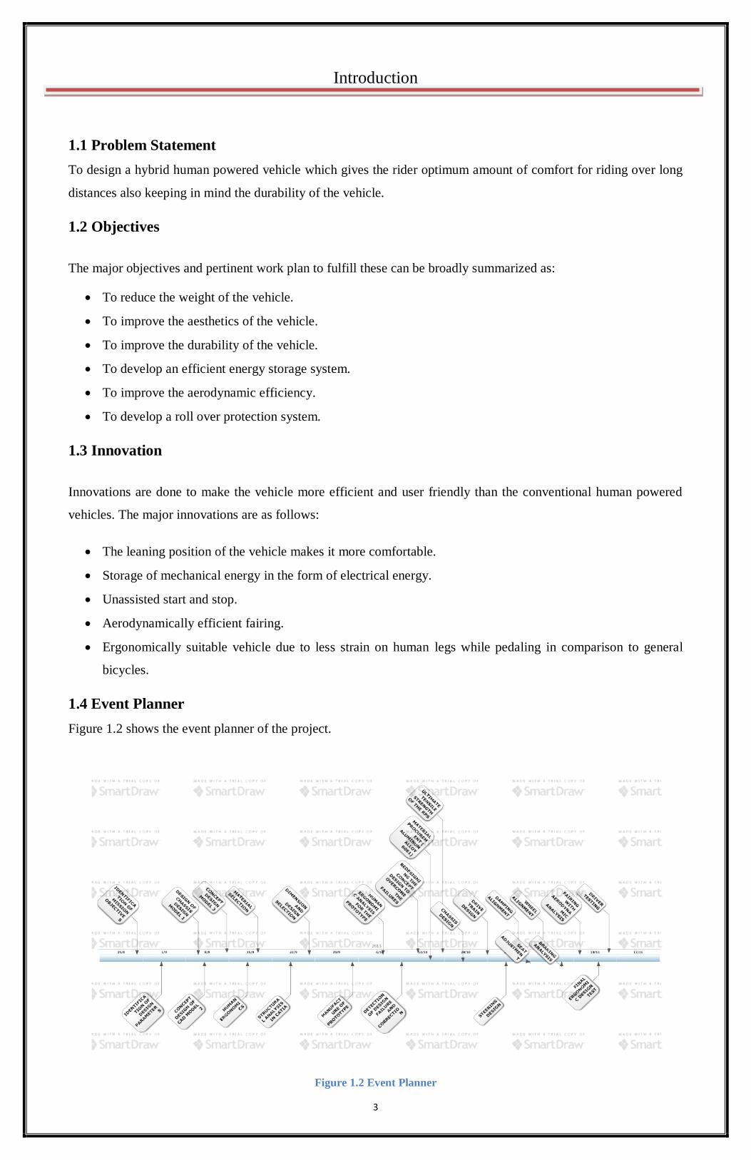
1.4 Event Planner
Figure 1.2 shows the event planner of the project.
Figure 1.2 Event Planner

4
Chapter 2
Literature Review
5
Chapter 2: Literature Review
2.1 Ergonomics
Improving ergonomics means designing the user-interface to make it more compatible with the task and the user.
This makes it easier to use and more resistant to errors that people are known to make. Changing the work
environment to make it safer and more appropriate for the task. Changing the task to make it more compatible with
user characteristics. [1]
2.2 Anthropometry
For design purposes, the criteria for deciding what constitutes a „population‟ are functional and are related directly
to the problem at hand. The word „anthropometry‟ means measurement of the human body. It is derived from the
Greek words „anthropos‟ (man) and „metron‟ (measure). The first step in designing is to specify the user population
and then to design to accommodate as wide a range of users as possible –normally 90% of them. Well designed
products acknowledge and allow for the inherent variability of the user population. [2]
2.2.1 Statistical treatment of anthropometric data
Designing for a person demands dimensional variations to be well fitted. When designing for mass use & for
unknown individuals, one of the most relevant statistical interpretations & considerations is the percentile value of
the collected data taken from a specific population group. [3]
2.2.2 Percentiles
Percentiles are the statistical values of a allotment of variables transferred into a hundred scale. These values of
anthropometric data can be calculated from cumulative frequency graphs and arithmetically. [3]
Professor Debkumar Chakrabarti in his book “Indian Anthropometric Dimensions” has listed all anthropometric
variables and some related Indian data.[4]
2.3 Previous Research
Lucerne[5]
(2009), printed a paper which considers the progress and the extend of human powered vehicle
(HPV) equipment in order to clarify the intertwine of air force and also to indicate the possibilities that are
natural in more competent bicycles. It urbanized and widespread previous work in this area by Kyle and by
Beaujon, , amongst others, together with the studies and findings a mass of enthusiasts, riders and historians.
It focused not only on the confinements imposed in cycle sports but also the ways in which broader social
changes also link with the processes of novelty.
Danny Too[6]
(2003), considered a large number of human body factors that affect cycling conditions. These
factors can often be categorized into three categories: (1) environmental factors, (2) intrinsic human body
factors, and (3) extrinsic motorized factors. The interaction of different factors within a category can be
complex, but need to be examined and understood if efficient human-powered vehicles are to be developed.
The purpose of his paper is two-fold: (1) to observe the factors in each

6
Literature Review
group, their relations, and how they affect presentation in human-powered vehicles, and (2) to provide a
human machine performance replica for these factors.
Too and Landwer[7]
(2008), considered the boundaries of performance in human powered vehicles (HPV)
which in order to be reached, developers of HPVs need to understand how the body interacts with the
vehicle to increase propulsive forces, and how the vehicle interacts with the environment to decrease
resistive forces. Their paper studied, contrasted and summarized the various research literature on both erect
and recumbent cycling positions regarding how orderly changes in peripheral motorized variables (seat-tube-
angle, seat-to-pedal distance, crank arm length) interact with interior human body factors (hip, knee, and
ankle angles) to affect power creation and cycling performance.
Julian Edgar[8]
(2007), studied several spring material by contrasting their cut off, density and pressure
forces. He found the lightest possible spring to be used. Steel coil springs last long and are compacted.
Airbag spring is long way compact and is light weight.
Benjamin Thomas Stein[9]
considered an internal cycle ergo indicator that allows for viable and entertaining
mountain bike cyclists to replicate uphill conditions with controlled and managed pedaling. While dealing
with an uphill condition, with or without a climbing mechanism, the cyclist body may not be in the same
position as while pedaling outdoors. This possible dissimilarity in body position may have training
requirements. The purpose of this study was to know if the dissimilarity was due to human body factors or
due to motorized factors.
7
Chapter 3
Methodology

8
Chapter 3: Methodology
3.1 Material Selection
After brainstorming frame geometries, the frame material was determined to balance the various properties of
strength, weight, fabrication time, material cost and aerodynamic effects. The material considered were Stainless
Steel AISI 304, Chromoly, Aluminium 6061-T6. The choice was determined using a decision matrix as
documented in Table 3.1 and it was found that stainless steel was the best frame material to use.
Table 3.1 Material Selection
PROPERTIES
STAINLESS
STEEL
AISI 304
(Annealed)
CHROMOLY
ALUMINIU
M
6061-O
Density (x1000 kg/m3) 7.9 7.8 2.7
Elastic Modulus (GPa) 200 205 69
Poisson’s Ratio 0.26 0.28 0.33
Yield Strength (MPa) 207-552 380-1215 241-275
%Elongation 12-40 28.2
Melting Point(0C) 1400 1432 582
Brinell Hardness 201 HBW 197-375
HBW
95 HBW
Bulk Modulus (GPa) 130 - 67
UTS (MPa) 620 560-1310 310
Elongation at Break (%) 35 12-26 14
Strength to Weight Ratio (kNm/kg) 78 71-160 110
Shear Modulus (GPa) 100 - 34
Fatigue Strength Coefficient (MPa) 876 2294 383
Fatigue Ductility Coefficient 0.063 1.443 0.207
Fatigue Ductility Exponent, c -0.3069 -.7255 -0.628
Fatigue Strength exponent, b -0.1057 -0.1013 -0.053
Cyclic Strain Hardening Exponent,
n’
0.3419 0.1375 0.089
3.2 FEM Analysis of Aluminium 6061 tubes and Stainless steel
Analysis was done on 2 Tubes of aluminum alloy 6061 and Stainless Steel to compare the load bearing capacity of
the chosen aluminum 6061, each of 40mm diameter and 2mm thickness. Loads of 3000N was applied on both the
tubes and deformation of 0.2mm was found on aluminum 6061 and 0.08mm was found on stainless steel tube as in
Fig 3.1 and Fig 3.2. This shows stainless steel with the least deformation is the best frame material to be used.

9
Methodology
Figure 3.1 Aluminium 6061 tubes
Figure 3.2 Stainless Steel

10
Design
Chapter 4

11
Chapter 4: Design
4.1 Frame Design
The frame was designed to place the rider in a position that would minimize frontal area as well as provide a shape
to fit a body of upheaval for a laminar flow fairing. Three concept designs were created, varying the general
position of the driver and thus a final frame setup was considered.
4.1.1 Concept 1
In this concept, as shown in Fig 4.1 effort in pedaling is large due to excess height of pedal axle.
As the rollover protection system is perpendicular to the chassis seating position, so that enough drag is
produced which reduces driver efficiency.
Ergonomically not suitable, as strain on human legs is more due to increased height of pedal axle.
Figure 4.1 Concept 1
4.1.2 Concept 2
Less effort in pedaling as compared to concept 1 due to decrease in pedal axle height.
Air drag is more as compared to concept 1 due to increased surface area of body cover as shown in Fig 4.2.
Figure 4.2 Concept 2
4.1.3 Structural Analysis of Concept 2
Load analysis on concept design 2 was done to determine design parameters.
Thickness of tube was taken as 7mm and material taken was aluminium alloy 6061.
Load analysis was done by applying load varying from 1000N to 5000N.
Static load applied on chassis by an average human being =1000N (approximately)

12
Design
Dynamic load applied on a vehicle by an average human being and by external forces from the road= 5000N
(approximately).
At 1000N, deformation produced is 0.5mm (max.)
At 2000N, deformation produced is 0.9mm (max.).
At 3500 N, deformation produced is 1.01mm (max)
At 4500N, deformation produced is 2.3 mm(max).
At 5000N, deformation produced is 2.55 mm(max).
Factor of safety at 5000N: 2(min).
However the load as much as 5000N is too large to be considered for a vehicle moving at 30-40 km/hr. and at such
So the concept is over engineered and dimensional parameters should be changed.
4.1.4 Human Ergonomics on Concept 2
Human ergonomics analysis was done to determine workspace of human limbs for average height of 5‟7”.
Analysis resulted in collision.
Analysis resulted in determination of dimensions of rollover protection system.
Length and position of steering handle was determined by the workspace of hand limbs.
Position of pedal axle and crank length was determined based on workspace of leg limb.
4.1.5 Concept 3 (Final Concept)
Lesser effort in pedaling as compared to concept 2 due to decreased height of pedal axle.
Reduction in air drag due to inclination given to RPS system with respect to chassis.
Ergonomically suitable due to less strain on human legs during pedaling as in Fig 4.3.
Figure 4.3 Concept 3
4.1.6 Human Ergonomics on Concept 3
A top-down design methodology was used to first locate the important components as shown in Fig 4.4(a),(b),(c).
To aid in fitting a human rider, a manikin was used in Catia V5. By designing to largest rider, the smallest riders
are guaranteed to fit inside the fairing.

13
Design
Fig. 4.4(a)
Fig.4.4(b)
Fig.4.4(c)
Figure 4.4 Human ergonomics on concept 3
4.1.7 Rollover Protection System
It was crucial that we perform analysis in addition to testing in order to validate our concept. We used the
composite analysis feature of ANSYS 14.0 to analyze our Rollover Protect under a top and side load, per
specification of the 2014 ASME HPVC rules.
For the purposes of simulation, it was assumed that the cross-section of the roll bar is constant and the bar was
treated as if it were perfectly connected to the roll bar. Material properties of stainless steel that we used are:
Young‟s Modulus of 69 GPa in the axial direction, a Poisson‟s ratio of 0.33, and an Ultimate Tensile Strength in
the axial direction of 310 MPa.

14
Design
4.2 Fairing Design
The lowest drag shape around an object would ideally have no flow separation, and maintain flow for as long as
possible before going turbulent. In order to maintain laminar flow for as long as possible, a favorable pressure
gradient is created by constantly sloping the slides outward. Three concept designs of the fairing were generated
for the frame as shown in Fig 4.5(a), 4.5(b) and 4.5(c).
Fig. 4.5(a)
Fig.4.5(b)
Fig.4.5(c)
Figure 4.5 Fairing
4.3 Computational Fluid Dynamics Analysis
We used a computational fluid dynamics (CFD) model to simulate the air flow around the fairing in order to
minimize aerodynamic drag. ANSYS FLUENT was used to test both headwind and crosswind conditions. Tests
15
Design
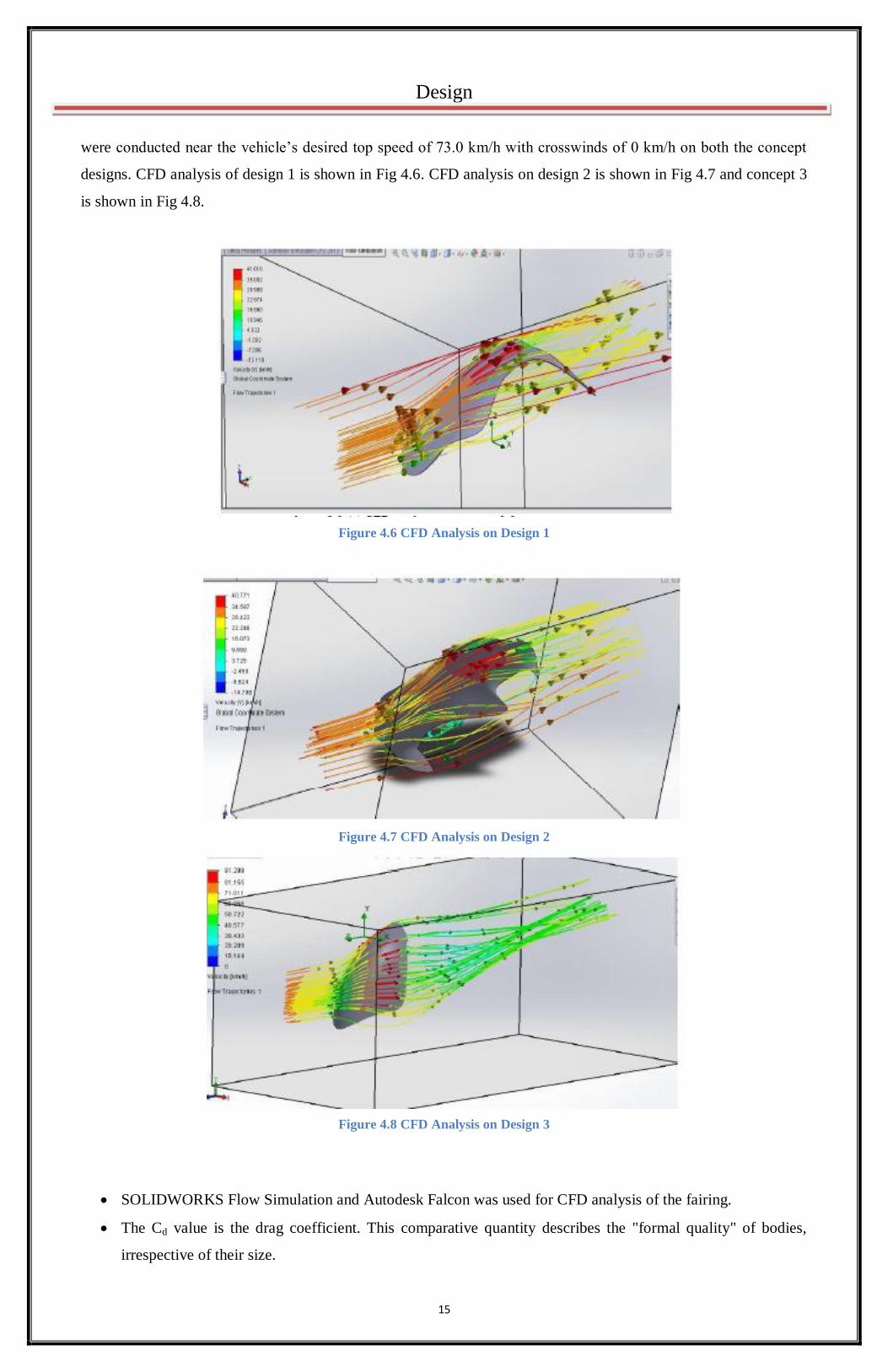
were conducted near the vehicle‟s desired top speed of 73.0 km/h with crosswinds of 0 km/h on both the concept
designs. CFD analysis of design 1 is shown in Fig 4.6. CFD analysis on design 2 is shown in Fig 4.7 and concept 3
is shown in Fig 4.8.
Figure 4.6 CFD Analysis on Design 1
Figure 4.7 CFD Analysis on Design 2
Figure 4.8 CFD Analysis on Design 3
SOLIDWORKS Flow Simulation and Autodesk Falcon was used for CFD analysis of the fairing.
The Cd value is the drag coefficient. This comparative quantity describes the "formal quality" of bodies,
irrespective of their size.
16
Design
A number of factors influence the Cd value, including the vehicle shape. The lower this value, the more
aerodynamically efficient the vehicle‟s design. So concept 3 was found to be best as can be seen from Table
4.1.
A precise statement regarding the vehicle‟s aerodynamics can only be made once both the Cd value and the
vehicle‟s frontal area (the projection of the vehicle‟s front outline onto a plane surface) are known.
Table 4.1 CFD Analysis
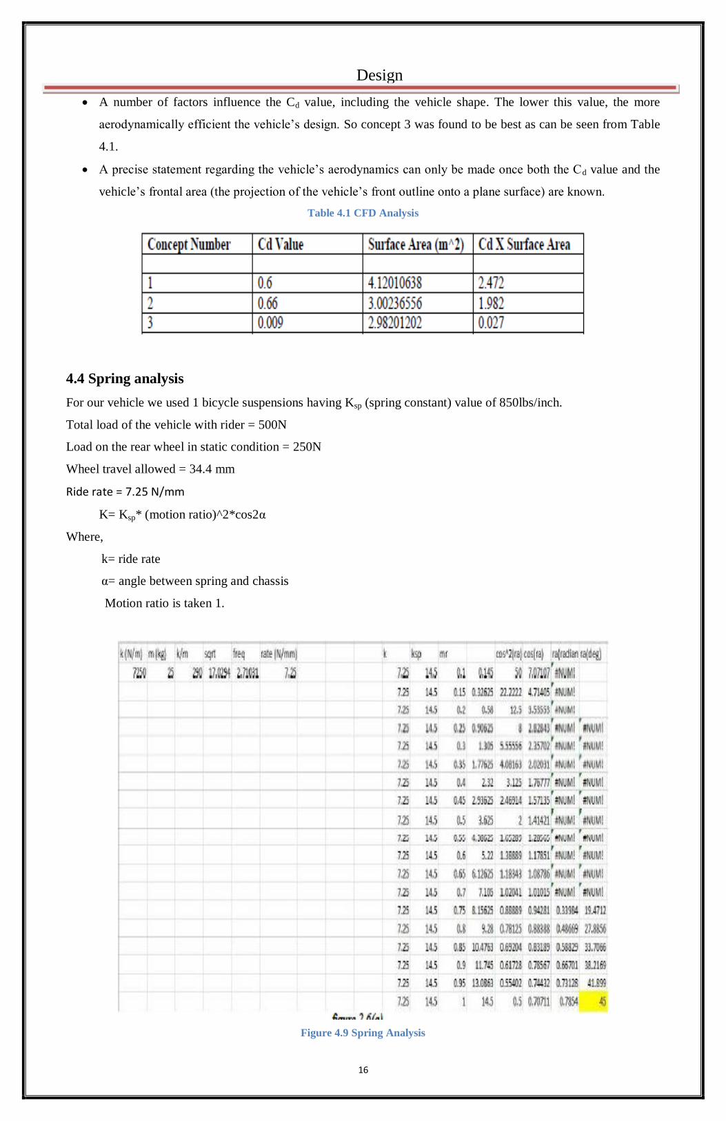
4.4 Spring analysis
For our vehicle we used 1 bicycle suspensions having Ksp (spring constant) value of 850lbs/inch.
Total load of the vehicle with rider = 500N
Load on the rear wheel in static condition = 250N
Wheel travel allowed = 34.4 mm
Ride rate = 7.25 N/mm
K= Ksp* (motion ratio)^2*cos2α
Where,
k= ride rate
α= angle between spring and chassis
Motion ratio is taken 1.
Figure 4.9 Spring Analysis

17
Chapter 5
Drive Train Analysis
and Innovision
18
Chapter 5: Drive train analysis and Innovision
5.1 Drive Train
The drive train is one of the most important aspects of reliability for a Human Powered Vehicle. A well designed
drive train will make the HPV more efficient and user friendly as well as decrease excessive mechanical losses
improvise speed and increase the reliability of the HPV.
In our HPV we have introduced rear wheel drive system over front wheel and internal gear hub. The advantages of
rear wheel drive are that it does not allow torque steer with the pedal stroke and it leaves plenty of space for the
gearing system assembly. The cassette and derailleur can be placed at the rear wheel well out of the way of rider‟s
feet. Additionally it is light weight and is much less expensive. On the contrary they have longer drive chain and
require more chain tensioners which we have overcome in our design by optimizing the dimensional accuracy. As
per our design which includes two wheels at the front, the front wheel drive systems have their share of drawbacks.
In the above case, to improvise the steady state condition while taking a sharp turn we need to use a differential
which will increase the weight of the vehicle as well as hamper our economic viability. Lastly, though the internal
gear hubs are more effective while shifting of the gear but are less efficient than a cassette- derailleur system due to
multiple planetary gear connection which causes more friction and high energy losses. Hence looking forward
towards the advantages of a rear cassette derailleur system over front wheel and internal gear hubs we opt for the
rear wheel drive train. Further analysis was done to determine the best combination of crank chain ring and cassette
that will be the best for our top speed goal and also for rider comfort.
5.2 Determining the Velocity of HPV
For a given cadence, gear ratio and the outer radius of the rear wheel we determine the value of the speed of the
HPV as:
V (km/hr.) = R (m) * GEAR RATIO * CADANCE (rpm) * 2π/60 * 18/5
Let the front sprocket is rotated by the driver at a cadence (N rpm). So the rear sprocket rotates at a cadence of (N*
GEAR RATIO).
The velocity of rear wheel of radius R for this rpm is given by
V= ω*R = N*GEAR RATIO*2π/60*R*3600/1000 (km/hr.).
According to ISO 5775 designation for wheels our team has selected the size of rear wheel as 28 inch * 11/8 inch *
9/8 inch. We have used 30 speed shimano gears in our drive train which involves 50T, 39T and 30T at the front
sprocket and the combination of 25,23,21,19,17,15,14,13,12,11 at the rear sprocket.
The velocity calculation for different gear combination and cadence are shown in Table 5.1, 5.2, 5.3.
Drive train analysis and Innovision

19
Table 5.1 Calculation of speed for different values of cadence with respect to 50T chain ring
Table 5.2 Calculation of speed for different values of cadence with respect to 39T chain ring
Table 5.3 Calculation of speed for different values of cadence with respect to 30T chain ring
20
Drive train analysis and Innovation
Thus we have finally achieved a theoretical top speed of 73.08km/hr. with the combination of 50T-11T for a
cadence of 120 rpm with the wheel size of 0.7112m as diameter.
5.3 Innovations
5.3.1 Collision protection system
Objective: To prevent the vehicle from colliding with any passerby or other vehicle.
Need: Sometimes the vehicle may go out of control and hit any nearby person or vehicle leading to casualties. Such
a system would prevent it from happening.
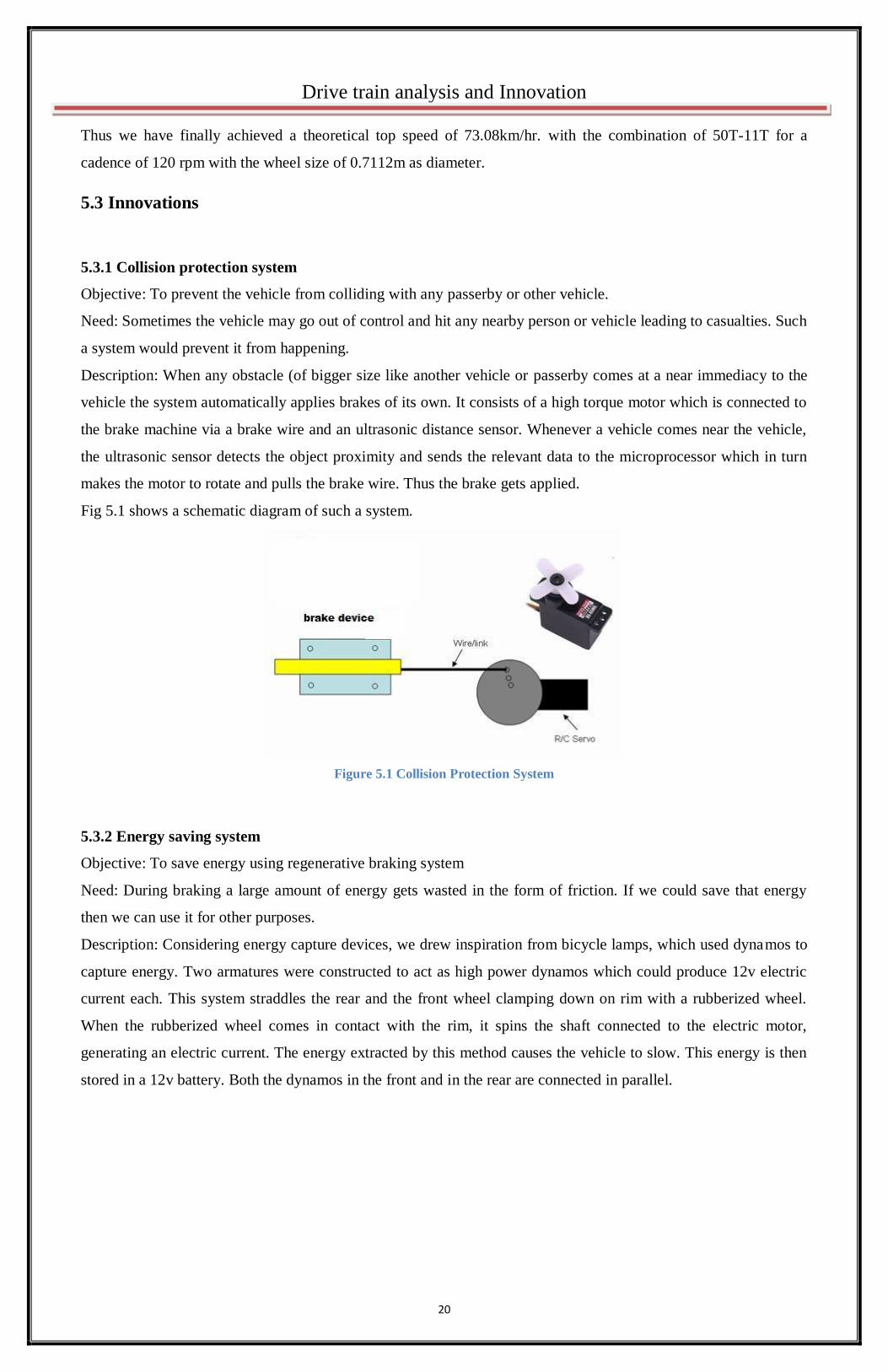
Description: When any obstacle (of bigger size like another vehicle or passerby comes at a near immediacy to the
vehicle the system automatically applies brakes of its own. It consists of a high torque motor which is connected to
the brake machine via a brake wire and an ultrasonic distance sensor. Whenever a vehicle comes near the vehicle,
the ultrasonic sensor detects the object proximity and sends the relevant data to the microprocessor which in turn
makes the motor to rotate and pulls the brake wire. Thus the brake gets applied.
Fig 5.1 shows a schematic diagram of such a system.
Figure 5.1 Collision Protection System
5.3.2 Energy saving system
Objective: To save energy using regenerative braking system
Need: During braking a large amount of energy gets wasted in the form of friction. If we could save that energy
then we can use it for other purposes.
Description: Considering energy capture devices, we drew inspiration from bicycle lamps, which used dynamos to
capture energy. Two armatures were constructed to act as high power dynamos which could produce 12v electric
current each. This system straddles the rear and the front wheel clamping down on rim with a rubberized wheel.
When the rubberized wheel comes in contact with the rim, it spins the shaft connected to the electric motor,
generating an electric current. The energy extracted by this method causes the vehicle to slow. This energy is then
stored in a 12v battery. Both the dynamos in the front and in the rear are connected in parallel.

21
Chapter 6
Results and Discussion
22
Chapter 6: Results and Discussion
6.1 Results of Concept Design
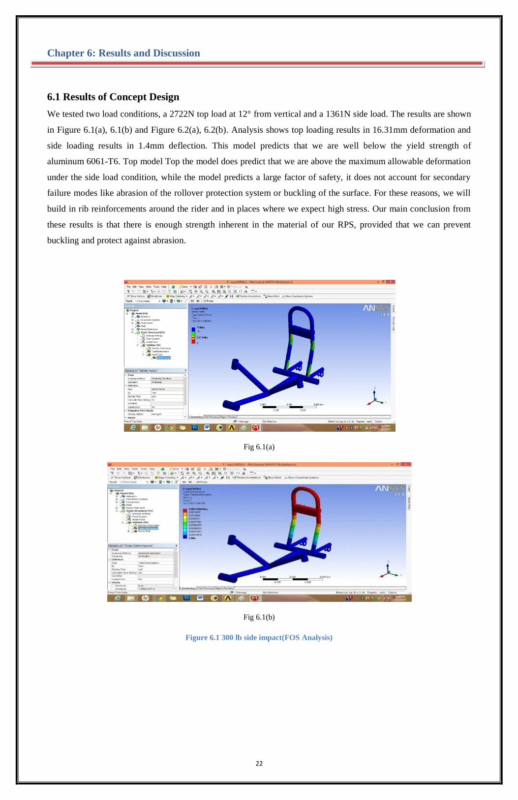
We tested two load conditions, a 2722N top load at 12° from vertical and a 1361N side load. The results are shown
in Figure 6.1(a), 6.1(b) and Figure 6.2(a), 6.2(b). Analysis shows top loading results in 16.31mm deformation and
side loading results in 1.4mm deflection. This model predicts that we are well below the yield strength of
aluminum 6061-T6. Top model Top the model does predict that we are above the maximum allowable deformation
under the side load condition, while the model predicts a large factor of safety, it does not account for secondary
failure modes like abrasion of the rollover protection system or buckling of the surface. For these reasons, we will
build in rib reinforcements around the rider and in places where we expect high stress. Our main conclusion from
these results is that there is enough strength inherent in the material of our RPS, provided that we can prevent
buckling and protect against abrasion.
Fig 6.1(a)
Fig 6.1(b)
Figure 6.1 300 lb side impact(FOS Analysis)

23
Results and Discussion
Fig 6.2(a)
Fig 6.2(b)
Figure 6.2 600 lb top impact (FOS Analysis)
6.2 Final Result and Design
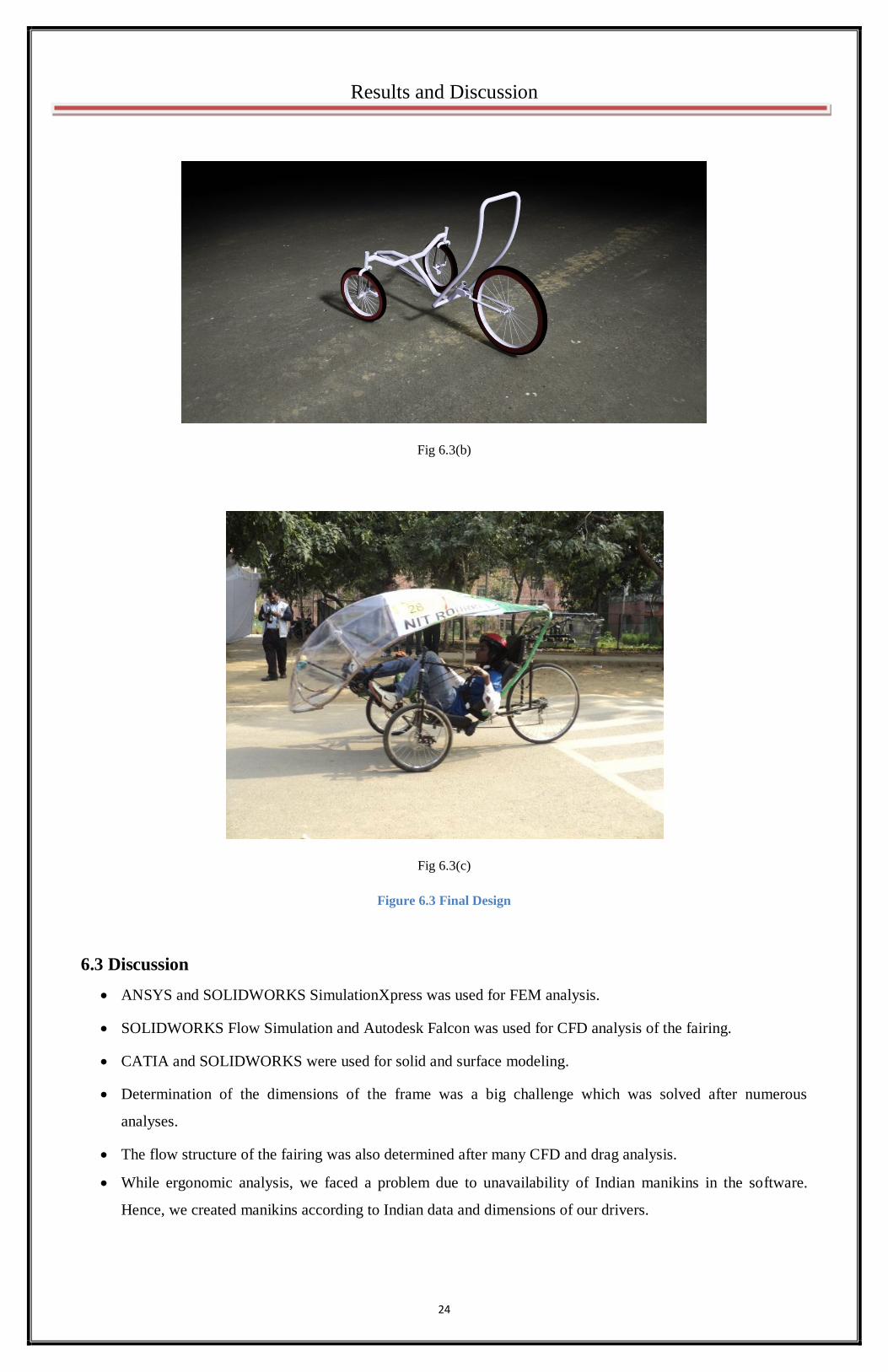
Top force as less as 0.014N and downward force as high as 1.1N was found. So Design 3 was finalized to be used
in our vehicle. The above analysis shows concept design 3 to be a better design with drag. Based on above analysis
we reached on a final design as shown in the figure 6.3(a), 6.3(b), 6.3(c).
Fig 6.3(a)
24
Results and Discussion
Fig 6.3(b)
Fig 6.3(c)
Figure 6.3 Final Design
6.3 Discussion
ANSYS and SOLIDWORKS SimulationXpress was used for FEM analysis.
SOLIDWORKS Flow Simulation and Autodesk Falcon was used for CFD analysis of the fairing.
CATIA and SOLIDWORKS were used for solid and surface modeling.
Determination of the dimensions of the frame was a big challenge which was solved after numerous
analyses.
The flow structure of the fairing was also determined after many CFD and drag analysis.
While ergonomic analysis, we faced a problem due to unavailability of Indian manikins in the software.
Hence, we created manikins according to Indian data and dimensions of our drivers.

25
Chapter 7
Conclusions
26
Chapter 7: Conclusions
7.1 Product
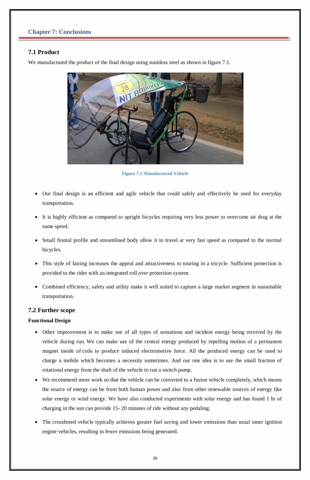
We manufactured the product of the final design using stainless steel as shown in figure 7.1.
Figure 7.1 Manufactured Vehicle
Our final design is an efficient and agile vehicle that could safely and effectively be used for everyday
transportation.
It is highly efficient as compared to upright bicycles requiring very less power to overcome air drag at the
same speed.
Small frontal profile and streamlined body allow it to travel at very fast speed as compared to the normal
bicycles.
This style of fairing increases the appeal and attractiveness to touring in a tricycle. Sufficient protection is
provided to the rider with an integrated roll over protection system.
Combined efficiency, safety and utility make it well suited to capture a large market segment in sustainable
transportation.
7.2 Further scope
Functional Design
Other improvement is to make use of all types of sensations and incident energy being received by the
vehicle during run. We can make use of the central energy produced by repelling motion of a permanent
magnet inside of coils to produce induced electromotive force. All the produced energy can be used to
charge a mobile which becomes a necessity sometimes. And our one idea is to use the small fraction of
rotational energy from the shaft of the vehicle to run a switch pump.
We recommend more work so that the vehicle can be converted to a fusion vehicle completely, which means
the source of energy can be from both human power and also from other renewable sources of energy like
solar energy or wind energy. We have also conducted experiments with solar energy and has found 1 hr of
charging in the sun can provide 15- 20 minutes of ride without any pedaling.
The crossbreed vehicle typically achieves greater fuel saving and lower emissions than usual inner ignition
engine vehicles, resulting in fewer emissions being generated.
27
Aesthetics and Ergonomics
The vehicle has been designed in such a way that it could attract attention. Though the frame could consist of
straight and curve lines in a fashioned way to make it more appealing.
The carrier can be given a slight curve structure so as to add to the aesthetics of the vehicle. The carrier also
serves as the support for the rollover protection system.
The fairing was designed to give a half bullet shape making it an addition on to the aesthetics of the vehicle.
The further improvement in the design of fairing can be made to make it look aesthetically sound while
minimizing the air drag.
A further improvement in the ergonomics of the vehicle can be done by adjusting the position of the pedals
so that the rider can ride for a long time without any strain in legs.
28
References
Bridger, RS, 1995, Introduction to Ergonomics, 3rd edition, McGraw-Hill, Inc.
Chakrabarti, DK, 1993, Indian Anthropometric Dimensions, National Institute of Design, McGraw-Hill, Inc.
http://www.academia.edu/267207/Energy_and_the_Bicycle__Human_Powered_Vehicles_in_Perspective
http://digitalcommons.brockport.edu/pes_facpub/99/
http://www.recumbents.com/forums/topic.asp?TOPIC_ID=4419
http://www.academia.edu/267207/Energy_and_the_Bicycle_-_Human_Powered_Vehicles_in_Perspective
http://digitalcommons.brockport.edu/pes_facpub/99/
http://www.recumbents.com/forums/topic.asp?TOPIC_ID=4419
http://network.bepress.com/explore/life-
sciences/kinesiology/?facet=publication_facet%3A%22Kinesiology%2C+Sport+Studies+and+Physical+Educat
ion+Faculty+Publications%22&facet=subject_facet%3A%22Human+powered+vehicles%22