design and application of composite right/left-handed transmission line based on complementary...
TRANSCRIPT

Design and Application of CompositeRight/Left-Handed Transmission Line Based onComplementary Meander Archimedean SpiralResonator
Ke Lu, Guang-ming Wang, Ya-wei Wang, Hui-yong Zeng
Missile Institute, Air Force Engineering University, Sanyuan 713800, China
Received 28 April 2011; accepted 4 August 2011
ABSTRACT: A novel composite right/left-handed transmission line based on the comple-
mentary meander Archimedean spiral resonator (CMASR) is proposed and investigated in
detail. The composite property of the proposed structure is demonstrated and the right-
handed frequency band is initially pointed out for the structure derived from the comple-
mentary Archimedean spiral resonator (CASR). One modified method of extracting the
lumped elements based on the analytical analysis is proposed to investigate the equivalent
circuit model. The results indicate that this method can accelerate the extracting process
effectively and the circuit model using the extracted elements can predict the property of
the given structure excellently. Then, the influence of primary geometrical parameters is
investigated through the parametric analysis, which provides the directive guideline. When
compared with CASR, CMASR can lower the operating frequency further with keeping the
effective area roughly constant. To explore and validate the composite property, one broad-
band bandpass filter is designed through tuning the left- and right-handed frequency bands
into the quasi-balance condition. The measured results indicate that the fractional band-
width is about 88.3%. VC 2012 Wiley Periodicals, Inc. Int J RF and Microwave CAE 00:000–000,
2012.
Keywords: complementary meander Archimedean spiral resonator; composite right/left-handed
transmission line; broadband bandpass filter
I. INTRODUCTION
The composite right/left-handed transmission line is a type
of one-dimensional metamaterial, which is the special for-
mation of the bulk left-handed media. This concept is pri-
marily utilized to design the microwave components with
the modified performance, such as phase shifter, branch
coupler, and leaky-wave antenna [1–3]. In the variety of
realized the composite right/left-handed transmission line,
the microstrip prototype composed of series gap on the con-
ducting strip and the complementary split rings resonators
have been investigated thoroughly, whereas the correspond-
ing equivalent circuit model and analytical theory have
been proposed to explain the operation principle [4–6].
Because of the composite property, there are two passbands
for this composite right/left-handed transmission line, one
at the lower frequency band with the backward wave prop-
erty, namely the left-handed behavior and the other at the
higher frequency band with forward wave (right-handed)
behavior, which is derived from the parasitic elements of
the host line. Then, the given left-handed, right-handed
passbands and the passband of the second resonance were
integrated together to get ultra wide passband through intro-
ducing additional grounded stubs [6, 7]. Moreover, the
given structures have been applied to miniaturize the power
dividers [8]. The complementary split rings improved with
fractal geometries have been proposed to get the miniaturi-
zation of the metamaterial cells [9]. In Refs. [10, 11], one
novel compact metamaterial cell, the complementary Archi-
medean spiral resonator (CASR) was proposed. This cell
was utilized to replace the complementary split rings reso-
nator to synthesis the left-handed transmission line, which
opens a new door to design the composite right/left-handed
transmission line. The total attention in Ref. [10] was
Correspondence to: K. Lu; e-mail: [email protected]
VC 2012 Wiley Periodicals, Inc.
DOI 10.1002/mmce.20571Published online in Wiley Online Library
(wileyonlinelibrary.com).
1
focused on the left-handed passband while the influence of
the geometrical parameters and the right-handed frequency
band were not included. Recently, one novel transmission
line with two composite right/left-handed passbands has
been proposed in Ref. [12].
In this article, one improved version of CASR, the
complementary meander Archimedean spiral resonator
(CMASR) is proposed and investigated. CMASR is real-
ized through meandering CASR with the sine. The mean-
der Archimedean spiral has been applied to design the
miniaturized antennas due to its special geometrical pat-
tern [13, 14]. Moreover, it is demonstrated that the proto-
type based on CMASR satisfies the long-wavelength limit
so that the given prototype has very compact dimension.
Through extracting the phased constant, the composite
property of the given structure composed of series gap
and CMASR is demonstrated. It is demonstrated that
CMASR may be the only effective method to lower the
operating frequency of CASR. Then, the parametric analy-
sis of the primary geometrical parameters of CMASR is
implemented, and the tuning rules to accelerate the design
process are achieved. To verify the above analysis, one
broadband bandpass filter is designed through adjusting
the left and right-handed frequency bands into the quasi-
balance condition. After optimization, one prototype is
fabricated and measured. The measured result indicates
that the lower and higher cutoff frequencies of the pass-
band are 1.48 and 3.75 GHz, respectively. Thus, the frac-
tional bandwidth of 88.3% has been achieved.
II. PROPERTY OF THE PROPOSED STRUCTURE ANDEQUIVALENT CIRCUIT MODEL
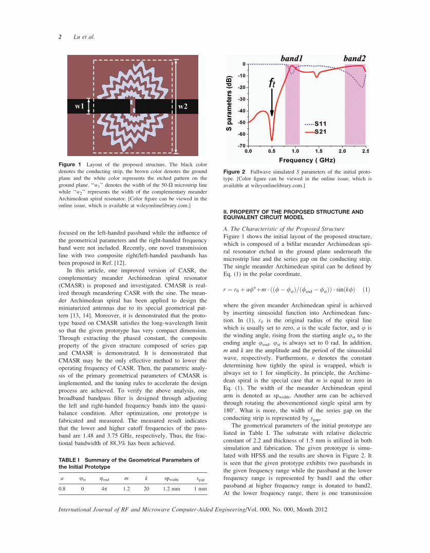
A. The Characteristic of the Proposed StructureFigure 1 shows the initial layout of the proposed structure,
which is composed of a bifilar meander Archimedean spi-
ral resonator etched in the ground plane underneath the
microstrip line and the series gap on the conducting strip.
The single meander Archimedean spiral can be defined by
Eq. (1) in the polar coordinate.
r ¼ r0 þ a/nþm � ðð/� /stÞ=ð/end � /stÞÞ � sinðk/Þ ð1Þ
where the given meander Archimedean spiral is achieved
by inserting sinusoidal function into Archimedean func-
tion. In (1), r0 is the original radius of the spiral line
which is usually set to zero, a is the scale factor, and u is
the winding angle, rising from the starting angle ust to the
ending angle uend. ust is always set to 0 rad. In addition,
m and k are the amplitude and the period of the sinusoidal
wave, respectively. Furthermore, n denotes the constant
determining how tightly the spiral is wrapped, which is
always set to 1 for simplicity. In principle, the Archime-
dean spiral is the special case that m is equal to zero in
Eq. (1). The width of the meander Archimedean spiral
arm is denoted as spwidth. Another arm can be achieved
through rotating the abovementioned single spiral arm by
180�. What is more, the width of the series gap on the
conducting strip is represented by sgap.The geometrical parameters of the initial prototype are
listed in Table I. The substrate with relative dielectric
constant of 2.2 and thickness of 1.5 mm is utilized in both
simulation and fabrication. The given prototype is simu-
lated with HFSS and the results are shown in Figure 2. It
is seen that the given prototype exhibits two passbands in
the given frequency range while the passband at the lower
frequency range is represented by band1 and the other
passband at higher frequency range is donated to band2.
At the lower frequency range, there is one transmission
Figure 1 Layout of the proposed structure. The black color
denotes the conducting strip, the brown color denotes the ground
plane and the white color represents the etched pattern on the
ground plane. ‘‘w1’’ denotes the width of the 50-X microstrip line
while ‘‘w2’’ represents the width of the complementary meander
Archimedean spiral resonator. [Color figure can be viewed in the
online issue, which is available at wileyonlinelibrary.com.]
TABLE I Summary of the Geometrical Parameters ofthe Initial Prototype
a ust uend m k spwidth sgap
0.8 0 4p 1.2 20 1.2 mm 1 mm
Figure 2 Fullwave simulated S parameters of the initial proto-
type. [Color figure can be viewed in the online issue, which is
available at wileyonlinelibrary.com.]
2 Lu et al.
International Journal of RF and Microwave Computer-Aided Engineering/Vol. 000, No. 000, Month 2012
zero (ft) at the frequency of 0.5 GHz and w2 of the initial
prototype is 22.5 mm.
First, it is necessary to determine whether the proposed
prototype satisfies the long-wavelength limit, which is
necessary for the investigation of metamaterial [15]. The
effective dielectric permittivity of the proposed is calcu-
lated using Eq. (2) given in Ref. [16].
ee ¼ er þ 1
2þ er � 1
2ð1þ 12
h
w1Þ�1
2w1
h�1 (2)
where h is the thickness of the substrate. The calculated
effective dielectric permittivity is equal to 1.87 and the
wavelength at the center frequency of the passband, 0.9
GHz is 243.7 mm. It is seen that w2 ¼ 22.5 mm is smaller
than one-tenth of 243.7 mm. To understand the propaga-
tion characteristics of the given unit, the phase constant bis extracted using Eq. (3). This equation is obtained from
the relation of the phase constant and the ABCD matrix
of the unit cell given in Ref. [17], integrating with the
associations of the ABCD and S matrices.
bd ¼ cos�1ð1� S11S22 þ S21S122S21
Þ (3)
where d is the length of the unit cell, which is constant in
this case.
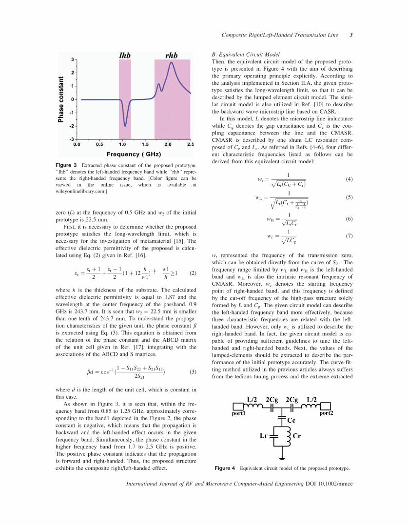
As shown in Figure 3, it is seen that, within the fre-
quency band from 0.85 to 1.25 GHz, approximately corre-
sponding to the band1 depicted in the Figure 2, the phase
constant is negative, which means that the propagation is
backward and the left-handed effect occurs in the given
frequency band. Simultaneously, the phase constant in the
higher frequency band from 1.7 to 2.5 GHz is positive.
The positive phase constant indicates that the propagation
is forward and right-handed. Thus, the proposed structure
exhibits the composite right/left-handed effect.
B. Equivalent Circuit ModelThen, the equivalent circuit model of the proposed proto-
type is presented in Figure 4 with the aim of describing
the primary operating principle explicitly. According to
the analysis implemented in Section II.A, the given proto-
type satisfies the long-wavelength limit, so that it can be
described by the lumped element circuit model. The simi-
lar circuit model is also utilized in Ref. [10] to describe
the backward wave microstrip line based on CASR.
In this model, L denotes the microstrip line inductance
while Cg denotes the gap capacitance and Cc is the cou-
pling capacitance between the line and the CMASR.
CMASR is described by one shunt LC resonator com-
posed of Cc and Lc. As referred in Refs. [4–6], four differ-
ent characteristic frequencies listed as follows can be
derived from this equivalent circuit model:
wt ¼ 1ffiffiffiffiffiffiffiffiffiffiffiffiffiffiffiffiffiffiffiffiffiffiffiffiLrðCC þ CrÞ
p (4)
wL ¼ 1ffiffiffiffiffiffiffiffiffiffiffiffiffiffiffiffiffiffiffiffiffiffiffiffiffiffiffiLrðCr þ 4
1Cgþ 4
Cc
Þq (5)
wH ¼ 1ffiffiffiffiffiffiffiffiffiLrCr
p (6)
wc ¼ 1ffiffiffiffiffiffiffiffiLCg
p (7)
wt represented the frequency of the transmission zero,
which can be obtained directly from the curve of S21. Thefrequency range limited by wL and wH is the left-handed
band and wH is also the intrinsic resonant frequency of
CMASR. Moreover, wc denotes the starting frequency
point of right-handed band, and this frequency is defined
by the cut-off frequency of the high-pass structure solely
formed by L and Cg. The given circuit model can describe
the left-handed frequency band more effectively, because
three characteristic frequencies are related with the left-
handed band. However, only wc is utilized to describe the
right-handed band. In fact, the given circuit model is ca-
pable of providing sufficient guidelines to tune the left-
handed and right-handed bands. Next, the values of the
lumped-elements should be extracted to describe the per-
formance of the initial prototype accurately. The curve-fit-
ting method utilized in the previous articles always suffers
from the tedious tuning process and the extreme extracted
Figure 4 Equivalent circuit model of the proposed prototype.
Figure 3 Extracted phase constant of the proposed prototype.
‘‘lhb’’ denotes the left-handed frequency band while ‘‘rhb’’ repre-
sents the right-handed frequency band. [Color figure can be
viewed in the online issue, which is available at
wileyonlinelibrary.com.]
Composite Right/Left-Handed Transmission Line 3
International Journal of RF and Microwave Computer-Aided Engineering DOI 10.1002/mmce

values of the lumped elements, because this method is
pure mathematical approach with the practical limitations
ignored. In this article, one modified method is proposed
to accelerate the extraction process and help to get the
appropriate values satisfying the practical limitation.
In view of the proposed circuit model, the series and
shunt impedances of this circuit model can be expressed
in the Eqs. (8) and (9), respectively.
ZS ¼ 1
jw2Cg
þ jwL
2(8)
ZP ¼ 1
jwCC
þjwLrjwCr
jwLr þ 1jwCr
(9)
The series and shunt impedance can satisfy the condition
as shown in the Eq. (10) at the special frequency, wp/2.
Zpðjwp=2Þ ¼ �Zsðjwp=2Þ (10)
According to the T-network property, at this frequency,
the phase of the transmission coefficient is equal to 90�,namely, U(S21) ¼ p/2. wp/2 can be directly determined
from the phase shift performance. For the initial proto-
type, this frequency is about 1.25 GHz. Then, the Eqs. (4)
and (6) are rewritten as shown in Eqs. (11) and (12).
Lr ¼ðwH
wtÞ � 1
ðwHÞ21
CC
(11)
Cr ¼ CC
ðwH
wtÞ2 � 1
(12)
Then, the corresponding items in the Eqs. (9) and (10) are
substituted with the Eqs. (11) and (12), respectively. One
simplified expression can be achieved as shown in Eq.
(13).
1
jwp=2CC
þ 1
jwp=2CC
Q ¼ �ZSðwp=2Þ ðw2H�w2
t Þw2p=2
ðw2Hþw2
t Þw2t
¼ Q
(13)
Thus, Cc can be expressed as follows:
CC ¼ jð1þ QÞwp=2:ZSðwp=2Þ (14)
In addition, there is the analytical equation for Cg, but it
is only able to provide an approximate value which is
good starting point for optimization. The value of Lderived from the transmission line calculator is also in
approximation. Simultaneously, wH can be roughly limited
within one narrow frequency band according to the simu-
lated S21. Therefore, the minor adjustment of Cg, L, andwH is necessary. When Cg, L, and wH are determined, the
four characteristic frequencies and the other lumped ele-
ments can be calculated using the above equations. In
general, the adjustment process is quite effective and
Figure 5 Comparison of the full-wave simulated and the circuit
simulated results for the initial prototype proposed in Section A.
[Color figure can be viewed in the online issue, which is avail-
able at wileyonlinelibrary.com.]
Figure 6 Comparison of the full-wave simulated and the circuit
simulated results for the prototype in case 2. The parameters
which are different from the ones of the initial prototype are pre-
sented in the inset. [Color figure can be viewed in the online
issue, which is available at wileyonlinelibrary.com.]
Figure 7 Comparison of the full-wave simulated and the circuit
simulated results for the prototype in case 3. In this case, the se-
ries gap is replaced with the interdigital capacitance with 10 fin-
gers. [Color figure can be viewed in the online issue, which is
available at wileyonlinelibrary.com.]
4 Lu et al.
International Journal of RF and Microwave Computer-Aided Engineering/Vol. 000, No. 000, Month 2012

convenient. To demonstrate that the given modal is gen-
eral and valid with firm evidence, the extraction process
aimed at three different prototypes is implemented. The
full-wave simulated results and the circuit simulated
results are compared in Figures 5–7, respectively. In these
figures, ‘‘cms’’ denotes the circuit model simulation and
‘‘fws’’ denotes the fullwave simulation. The extracted
results and the four characteristic frequencies are listed in
Tables II and III, respectively.
It is seen that, within the given frequency range, the
fullwave simulated results agree well with the circuit
simulated ones in all the cases. Especially, the four char-
acteristic frequencies describe the fullwave simulated
results excellently. Thus, the validity of the circuit model
and the proposed modified method is verified. It should be
noted that the given circuit model fails in the frequency
band over wc. This is the intrinsic limitations of the given
circuit model, because long-wavelength limit is not satis-
fied within the frequency band over wc. Some directive
guidelines can be obtained by using the circuit model. For
example, as shown in Tables II and III, the interdigital ca-
pacitance can lead to the increase of Cg and the left-
handed frequency band is closer to the right-handed fre-
quency band. Hence, it is potentially possible to achieve
broadband passband using CRHLTL based on CMASR.
III. INFLUENCE OF THE GEOMETRICAL PARAMETERS
When compared with CSRR, CASR can lower the operat-
ing frequency of the backward microstrip line greatly,
thanks to its intrinsic convoluted geometry [10]. If lower
operating frequency is required, the method utilizing frac-
tal geometries proposed in Ref. [9] is not very suitable for
CASR. First, the fractal geometries are not easy to model
and adjust in the electromagnetic software, because the
fractal geometries cannot be expressed by the analytical
equations. Moreover, for CMAR, its inner area is occu-
pied and the space between adjacent rings is quite limited.
Thus, the fractal geometries are difficult and complicated
to apply for CASR. In contrast, the proposed CMASR can
be modeled using the analytical equation, which will
surely facilitate the further investigation. Simultaneously,
the meander geometry can also elongate the electrical
length of the given resonator and lower the resonant fre-
quency as the fractal geometries. Thus, it is concluded
that CMASR is possibly the only effective method to
lower the resonant frequency of CASR. To demonstrate
the above effect, two different CRHLTLs are compared
and these two prototypes are loaded with CASR and
CMASR, respectively. Except m and k, other geometrical
parameters of these two prototypes are identical. The
simulated results are depicted in Figure 8.
As shown in Figure 8, the operating frequency of com-
posite right/left-handed transmission line (CRLHTL)
loaded with CMASR is lower than the one of CRLHTL
loaded with CASR �900 MHz. It means that the meander
geometry can lower the operating frequency to great
extent. Thus, the component based on CMASR is more
applicable in the low frequency band. To investigate
CRHL based on CMASR further, the parametric analysis
TABLE II Summary of the Extracted Lumped Elements
Cc (pF) Cg (pF) Cr (pF) L (nH) Lr (nH)
Case1 17.81 1.49 3.85 2.82 4.67
Case2 21.52 1.86 3.62 4.19 6.29
Case3 12.70 2.06 8.24 4.24 1.20
TABLE III Summary of the Four CharacteristicFrequencies
ft (GHz) fL (GHz) fH (GHz) fC (GHz)
Case1 0.500 0.806 1.185 2.451
Case2 0.400 0.662 1.053 1.800
Case3 1.000 1.257 1.594 1.700
Figure 8 Comparison of the fullwave-simulated S21 of
CRHLTLs loaded with CMSAR and CASR, respectively. For
CMASR, the geometrical parameters are as follows: a ¼ 0.8,
uend ¼ 2pm ¼ 0.8, k ¼ 16, spwidth ¼ 1.2 mm, sgap ¼ 1mm.
[Color figure can be viewed in the online issue, which is avail-
able at wileyonlinelibrary.com.]
Figure 9 Variation of the fullwave-simulated S parameters ver-
sus m. The other geometrical parameters are as follows: a ¼ 1,
uend ¼ 3p, k ¼ 20, spwidth ¼ 1.2 mm, sgap ¼ 1 mm. [Color figure
can be viewed in the online issue, which is available at
wileyonlinelibrary.com.]
Composite Right/Left-Handed Transmission Line 5
International Journal of RF and Microwave Computer-Aided Engineering DOI 10.1002/mmce
of the geometrical parameters is implemented. It is found
that two geometrical parameters, the period of the sinusoi-
dal wave-k and the width of the meander Archimedean
spiral arm-spwidth influence the frequency response to
small extent. For simplicity, the given results are not
depicted in detail, whereas the amplitude of the sinusoidal
wave-m and the ending angle-uend have great effect on
the frequency response. The parametric analysis of these
two parameters is depicted in Figures 9 and 10,
respectively.
As depicted in Figure 9, the increase of m makes the
passband move downward while other properties approxi-
mately remain unchanged, because the increased m elon-
gates the physical length of CMASR and the resonant fre-
quency moves downwards. Moreover, it should be noted
that this parameter is limited by the special geometry of
CMASR and it cannot be very high in practice. Thus, it
should be used to tune the frequency response in rela-
tively narrow range. Moreover, as shown in Figure 10, the
increase of uend will lower the passband to great extent.
Simultaneously, the bandwidth of the left-handed pass-
band is widened with the decrease of uend. Through the
above parametric analysis, the effective design guideline
to design the prototype satisfying the special requirement
is achieved which will accelerate the design procedure.
IV. DESIGN OF THE BROADBAND BANDPASS FILTER
In order to explore the composite right/left-handed prop-
erty of the proposed prototype, one broadband bandpass
filter is designed. In general, the given broad passband is
obtained through making the left-handed and right-handed
passband get close enough, namely tuning these two bands
into the quasi-balance condition. The conclusion derived
from the equivalent circuit model analysis in section 2.2
indicates that the right-handed frequency band can be
tuned by Cg and the increased Cg can be realized by
replacing the series gap with the interdigital capacitance.
On the other hand, the left-handed frequency band can be
controlled by the amplitude of the sinusoidal wave-m or
the ending angle-uend according to the parametric analysis
in Section III. As pointed out in Ref. [18], the accurate
derivation of the structure physical parameters from the
circuit element is complicated or even impossible. Thus,
the above conclusions just provide some directive guide-
line to get the required property while further optimization
is necessary. Under the given directive guidelines, the tun-
ing process is quite effective and the applicable filter per-
formance is achieved successfully. In order to validate the
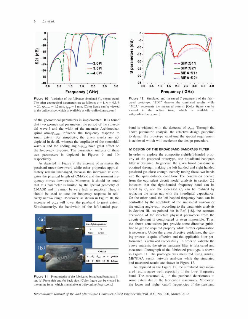
above analysis, the given bandpass filter is fabricated and
measured. Photograph of the fabricated prototype is shown
in Figure 11. The prototype was measured using Anritsu
ME7808A vector network analyzer while the simulated
and measured results are shown in Figure 12.
As depicted in the Figure 12, the simulated and meas-
ured results agree well, especially in the lower frequency
band. The measured S11 in the passband deteriorates to
some extent due to the fabrication inaccuracy. Moreover,
the lower and higher cutoff frequencies of the passband
Figure 10 Variation of the fullwave-simulated S21 versus uend.The other geometrical parameters are as follows: a ¼ 1, m ¼ 0.5, k¼ 20, spwidth ¼ 1.2 mm, sgap ¼ 1 mm. [Color figure can be viewed
in the online issue, which is available at wileyonlinelibrary.com.]
Figure 11 Photographs of the fabricated broadband bandpass fil-
ter. (a) Front side and (b) back side. [Color figure can be viewed in
the online issue, which is available at wileyonlinelibrary.com.]
Figure 12 Simulated and measured S parameters of the fabri-
cated prototype. ‘‘SIM’’ denotes the simulated results while
‘‘MEA’’ represents the measured results. [Color figure can be
viewed in the online issue, which is available at
wileyonlinelibrary.com.]
6 Lu et al.
International Journal of RF and Microwave Computer-Aided Engineering/Vol. 000, No. 000, Month 2012

are 1.48 and 3.75GHz, respectively. Thus, the fractional
bandwidth of 88.3% is achieved.
V. CONCLUSIONS
In this article, a novel composite right/left-handed transmis-
sion line based on the CMASR is proposed and investigated.
The composite property is demonstrated through extracting
the phase constant. One modified method of extracting the
lumped elements in the equivalent circuit model is proposed.
When compared with the CASR, CMASR can further lower
the operating frequency. Then, the parametric analysis of the
primary geometrical parameters is implemented to get the
design guideline. Through tuning the left-handed and right-
handed frequency bands into the quasi-balance condition, the
broadband bandpass characteristic has been achieved. One
broadband passband filter is fabricated and measured, and
good passband property is achieved. This structure will be
applied to design microwave components operating within
the low frequency band.
ACKNOWLEDGMENT
This work is supported by the National Natural Science
Foundation of China under Grant Nos. 60971118. The
authors thank the China North Electronic Engineering
Research Institute for the fabrication.
REFERENCES
1. J.P. Carrier and A.K. Skrivervik, Composite right/left-handed
transmission line metamaterial phase shifters (MPS) in
MMIC technology, IEEE Trans Microwave Theory Tech 54
(2006), 1582–1589
2. T. Ueda, N. Michishita, M. Akiyama, and T. Itoh, Dielectric-
resonator-based composite right/left-handed transmission lines
and their application to leaky wave antenna, IEEE Trans
Microwave Theory Tech 56 (2008), 2259–2269.
3. Z. Yu, H. Li, and H. Sai-ling, A tunable dual-broad-band
branch-line coupler utilizing composite right/left-handed
transmission lines, J Zhejiang Univ Sci A 6 (2005), 483–486.
4. M. Gil, J. Bonache, I. Gil, J. Garcı́a-Garcı́a, and F. Martı́n,
On the transmission properties of left-handed microstrip lines
implemented by complementary split rings resonators, Int J
Numer Model 19 (2006), 87–103.
5. J. Bonache, M. Gil, I. Gil, J. Garcı́a-Garcı́a, and F. Martı́n,
On the electrical characteristics of complementary metamate-
rial resonators, IEEE Trans Microwave Wireless Compon
Lett 16 (2006), 543–545.
6. M. Gil, J. Bonache, J. Selga, J. Garcı́a-Garcı́a, and F. Martı́n,
Broadband resonant-type metamaterial transmission lines,
IEEE Trans Microwave Wireless Compon Lett 17 (2007),
97–99.
7. M. Gil, J. Bonache, J. Garcı́a-Garcı́a, et al. Composite right/
left-handed metamaterial transmission lines based on comple-
mentary split-rings resonators and their applications to very
wideband and compact filter design, IEEE Trans Microwave
Theory Tech 55 (2007), 1296–1304.
8. M. Gil, J. Bonache, I. Gil, J. Garcı́a-Garcı́a, and F. Martı́n,
Miniaturisation of planar microwave circuits by using reso-
nant-type left-handed transmission lines, IET Microwave
Antennas Propag 1 (2007), 73–79.
9. V. Crnojevicı́-Bengin, V. Radonicı́, and B. Jokanovicı́, Fractal
geometries of complementary split-ring resonators, IEEE
Trans Microwave Theory Tech 56 (2008), 2312–2321.
10. O. Isik and K.P. Esselle, Backward wave microstrip lines
with complementary spiral resonators, IEEE Trans Antennas
Propag 56 (2008), 3173–3178.
11. O. Isik, K.P. Esselle, and Y. Ge, Compact microstrip and
CPW duplexers using complementary and conventional loga-
rithmic spiral resonators, Proc IEEE Int Symp Antennas
Propag (AP-S), Honolulu, HI, June 2007, pp. 4977–4980.
12. L.-L. Deng, Y.-N. Zhang, and D. Wu, A Compact transmission
line with two pairs of composite right/left-handed passbands,
Int. J. RF Microwave Comput Aided Eng 4 (2010), 441–445.
13. W. Ya-wei, W. Guang-ming, and Z. Hui-yong, Design of a
new meander Archimedean spiral antenna, Microwave Opt
Technol Lett 52 (2010), 2384–2387.
14. Z.H. Song, H.M. Li, H.Y. Yang, et al., Study on a miniatur-
ized meander Archimedean spiral antenna, Microwave J 25
(2009), 53–57.
15. T. Koschny, M. Kafesaki, E.N. Economou, and C.M. Soukou-
lis, Effective medium theory of left-handed materials, Phys
Rev Lett 93, 107402 (2004).
16. J.-S. Hong and M.J. Lancaster, Microstrip filters for RF/
microwave applications, Wiley, New York, 2001.
17. D. Pozar, Microwave Engineering, Wiley, New York, 1998.
18. I. Gil, J. Bonache, M. Gil, J. Garcı́a-Garcı́a, and F. Martı́n,
Accurate circuit analysis of resonant-type left handed trans-
mission lines with inter-resonator coupling, J Appl Phys 100
(2006), 074908.
BIOGRAPHIES
Ke Lu received the B.S. degree in
electrical engineering and M.S. degree
in the communication and information
systems in 2006 and 2009, respec-
tively, from the Air Force Engineering
University, where he is currently
working toward the Ph.D. degree. His
research interests include the design
and application of metamaterials.
Guang-Ming Wang received his BS
and MS degrees from the Missile
institute of Air Force Engineering
University, Xi’an, China, in 1982
and 1990, respectively, and his PhD
degree from the electronic science
and technology university, Chengdu,
China, in 1994. Then, He joined the
Air Force Engineering University as a professor in 2000
and is now the head of the Microwave Laboratory center
in it. His current interests include microwave circuits
based on metamaterials, antennas and propagation.
Composite Right/Left-Handed Transmission Line 7
International Journal of RF and Microwave Computer-Aided Engineering DOI 10.1002/mmce

Ya-Wei Wang received the B.S.
degree in electrical engineering and
M.S. degree in the microwave project
in 2008 and 2011, respectively, from
the Air Force Engineering University,
where he is currently working toward
the Ph.D. degree. His focuses on the
design of the ultra-wide band antenna.
Hui-yong Zeng received the B.S.
degree in electrical engineering and
M.S. degree in the microwave project in
2007 and 2010, respectively, from the
Air Force Engineering University, where
he is currently working toward the Ph.D.
degree. His research interests include the
design of the novel metamaterial.
8 Lu et al.
International Journal of RF and Microwave Computer-Aided Engineering/Vol. 000, No. 000, Month 2012