design and analysis of push rod rocker arm suspension ... · protect the passengers and goods....
TRANSCRIPT

DESIGN AND ANALYSIS OF PUSH ROD ROCKER
ARM SUSPENSION USING MONO SPRING
C.S.Vishnu1N.PraveenKumar2
K.SomeswarRao3G.VVSV.Prasad4
K.Koshore5M.jaswanrh Sai6
1 2 3 4 5 6 Department of Mechanical. K L University, guntur,
522502, INDIA [email protected]
Abstract
The main objective of this paper is to brief about mono spring rocker arm front suspension which is a semi independent suspension system. The main criterion of this project is to design a suspension system practically to a student formula hybrid vehicle. The dynamic loads are to be considered for the design of wheel assembly, frame, transmission, steering and braking systems, now loads are distributed to front and rear side. The stiffness of the spring is calculated by considering front loads. The design of the spring, damper, rocker arms and push rod was done by SOLID WORKS software. Later on the assembly of all parts and mono spring rocker arm front suspension system were designed. Analysis was done in LOTUS SHANK SUSPENSION ANALYSIS SOFTWARE, from the analysis the designs are said to be suitable for the end application.
AMS Subject Classification: 55P40, 97G80
Key Words: Mono spring, front suspension, stiffness, rocker arm, push rod. 1 Introduction
1.1. SUSPENSION
Main function of suspension is to reduce the vibrations and shocks that are occurring due to the irregularities on the road surface and to
International Journal of Pure and Applied MathematicsVolume 114 No. 9 2017, 465-475ISSN: 1311-8080 (printed version); ISSN: 1314-3395 (on-line version)url: http://www.ijpam.euSpecial Issue ijpam.eu
465
protect the passengers and goods. Suspension is used to maintain the steering stability of vehicle by increasing the friction between roads and tire surface and also to maintain good road handling by maximized contact between road and wheels of vehicle. One of the main function is to maintain all the steering parameters like camber, caster, toe in and out, kingpin inclination etc. and as we are going to design it for a formula hybrid car these parameters should be considered to maintain directional stability and rolling resistance.
1.2. TYPES OF SUSPENSION
Three type suspensions are independent, dependent and semi-independent. In This suspension consider it as semi-Independent.
2 Design of suspension system
2.1. Selection of material
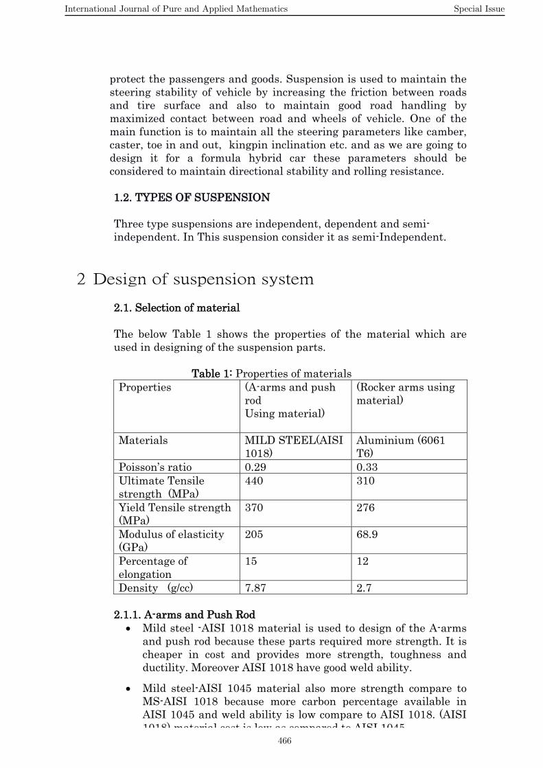
The below Table 1 shows the properties of the material which are used in designing of the suspension parts.
Table 1: Properties of materials
Properties (A-arms and push rod Using material)
(Rocker arms using material)
Materials MILD STEEL(AISI 1018)
Aluminium (6061 T6)
Poisson’s ratio 0.29 0.33 Ultimate Tensile strength (MPa)
440 310
Yield Tensile strength (MPa)
370 276
Modulus of elasticity (GPa)
205 68.9
Percentage of elongation
15 12
Density (g/cc) 7.87 2.7
2.1.1. A-arms and Push Rod • Mild steel -AISI 1018 material is used to design of the A-arms
and push rod because these parts required more strength. It is cheaper in cost and provides more strength, toughness and ductility. Moreover AISI 1018 have good weld ability.
• Mild steel-AISI 1045 material also more strength compare to MS-AISI 1018 because more carbon percentage available in AISI 1045 and weld ability is low compare to AISI 1018. (AISI 1018) material cost is low as compared to AISI 1045
International Journal of Pure and Applied Mathematics Special Issue
466

• Chromoly material is more strength but very high cost as compared to MS-AISI 1018 & MS-AISI 1045. Hence Mild steel -AISI 1018 is selected as the material for A-arms & push rod.
2.1.2. Rocker arm
• Aluminium-6061 T6 material is used to design the rocker arms because rocker arm required more strength, corrosion resistance and joining characteristics.
2.1.3. Spring • Chrome silicon material used to design of the spring because
spring required more stiffness, elastic, flexibility and absorbing the vibrations .chrome silicon have different properties. They are Density = 7.86 g/cc, Modulus of elasticity = 206.842 GPa, Minimum tensile strength = 235-300 psi * (103) or 206.842 MPa
2.2. Roll centre analysis Roll centre plays a important role in design of a suspension system. Roll centre is a point at the centre line of vehicle around which the vehicle rolls on its suspension, by combining both the roll centres at front and back roll axis is formed. These are determined by the instant centre of rotation it is a point where it forms a pivot point between two links. So, the roll centre is determined by projecting lines from instant centre to the centre of tire ground contact so this is done on each side of wheel from the front view and these both lines intersect at a point in the centre of the vehicle line that intersecting point is the roll centre of that specific front or back axle. To determine roll centres we have to fix wishbone lengths, track width, tie rod lengths. 2.3. Design of spring Before designing the spring have to assume some values basing on type of vehicle that is fabricated and through that have to find out the stiffness of the spring. Dynamic loads considered are: Weight at front side WF = 246.91lb Weight at rear side WR = 370.37lb Total weight WT = 617.29lb Dimensions of vehicle: Front track width tF = 4.66ft Rear track width tR = 4.66ft Wheel base l = 5.7ft CG(Centre of gravity) height from ground, h = 0.833ft Height from CG to Roll axis, H = 0.445ft Assuming the side to side symmetry ride rate
ω= ½𝜋�𝐾𝑅𝐹∗12∗32.2𝑊2
1.55 = ½𝜋�𝐾𝑅𝐹∗12∗32.2𝑊2
=) KR = 28.37lb/in
International Journal of Pure and Applied Mathematics Special Issue
467

Where ωis the natural frequencies the roll rates Kφ = 12∗𝐾𝑅𝐹∗𝑡2𝐹
2 = 3696.4lb-ft/rad
So that obtained all the required values for calculating the spring stiffness. Wheel rate KW = 𝐾𝑅𝐹∗𝐾𝑇
𝐾𝑇−𝐾𝑅𝐹 = 29.19lb/in
The stiffness of the spring KW = Ks(IR)2 KS = 116.76lb/in By using stiffness values calculate the required no. of coils, mean diameter of coil, coil diameter, and pitch of the spring 2.3.1Specifications of spring Coil diameter, d = 8.8mm Mean diameter, D = C*d = 79.2mm To calculate no. of coils the below formula is used K = 𝐺∗𝑑^4
8∗𝐷3∗𝑛
No. of active coils, na = 6 No. of inactive coils, nin = 2 Solid length, lsolid = 70.4mm Free length, lfree = 188.3mm pitch, = 31.3mm spring travel, = 117.9mm
International Journal of Pure and Applied Mathematics Special Issue
468

3 Design of Assembly
3.1Solid works modelling Solid works is modelling software which allows 3D- modelling and 2-D drafting of elements. In order to perform the analysis of spring in Ansys, it is necessary to model the spring in any of the modelling software's such as Pro-Engineers, Catia or Solid Works, etc. We have selected to use Solid works modelling software because of its availability.
3.2. Push Rod As the name in fig.2 push rod suggests which means it pushes the rocker arm when bump occurs. Using this we can also adjust the ride height of the vehicle.
Fig.2 Push Rod
3.3Rocker Arm Fig.3 rocker arm is which transmits motion from the tire to the spring with the help of push rod .where as using this can maintain the motion ratio required for the vehicle and also helps to reduce aerodynamic drag occurred due to the spring in formula cars.
Fig.3 Rocker Arm
3.4. Spring and Damper As of in Fig.4 spring and Damper is used to absorb heavy shocks and damp shock impulses. Where as only spring can absorb vibrations but it cannot be stiff while damping, so to control the damping damper is used in it. It helps in improved ride quality and handling while travelling on a rough road.
Fig.4 spring and Damper
International Journal of Pure and Applied Mathematics Special Issue
469
4 Analysis in ansys software
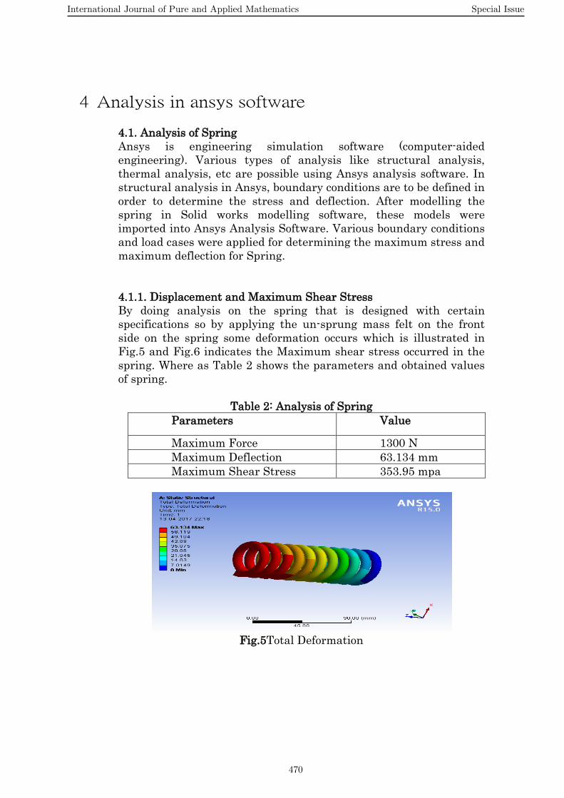
4.1. Analysis of Spring Ansys is engineering simulation software (computer-aided engineering). Various types of analysis like structural analysis, thermal analysis, etc are possible using Ansys analysis software. In structural analysis in Ansys, boundary conditions are to be defined in order to determine the stress and deflection. After modelling the spring in Solid works modelling software, these models were imported into Ansys Analysis Software. Various boundary conditions and load cases were applied for determining the maximum stress and maximum deflection for Spring. 4.1.1. Displacement and Maximum Shear Stress By doing analysis on the spring that is designed with certain specifications so by applying the un-sprung mass felt on the front side on the spring some deformation occurs which is illustrated in Fig.5 and Fig.6 indicates the Maximum shear stress occurred in the spring. Where as Table 2 shows the parameters and obtained values of spring.
Table 2: Analysis of Spring
Parameters Value
Maximum Force 1300 N Maximum Deflection 63.134 mm Maximum Shear Stress 353.95 mpa
Fig.5Total Deformation
International Journal of Pure and Applied Mathematics Special Issue
470
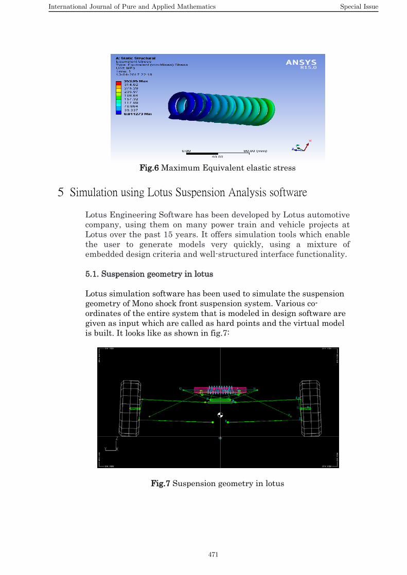
Fig.6 Maximum Equivalent elastic stress
5 Simulation using Lotus Suspension Analysis software
Lotus Engineering Software has been developed by Lotus automotive company, using them on many power train and vehicle projects at Lotus over the past 15 years. It offers simulation tools which enable the user to generate models very quickly, using a mixture of embedded design criteria and well-structured interface functionality. 5.1. Suspension geometry in lotus Lotus simulation software has been used to simulate the suspension geometry of Mono shock front suspension system. Various co-ordinates of the entire system that is modeled in design software are given as input which are called as hard points and the virtual model is built. It looks like as shown in fig.7:
Fig.7 Suspension geometry in lotus
International Journal of Pure and Applied Mathematics Special Issue
471

5.2 Plot of camber angle Fig.8 shows the change in camber angle for a rebound and bump for the particular design of the suspension model where the camber is between -2.5 to 2.5.
Fig.8 Graph plot between camber and bump
6 CONCLUSION Mono shock front suspension system for a formula car is practically designed and observed how it works. Analysis is done on every part of the system. It resulted that good handling, good suspension travel and it also reduces the un-sprung mass. The main disadvantage is as the spring is mounted between two rocker arms directly while cornering it is not able to retain the wheels straight as the load is transferring to one side while cornering. The future work can be done: Suspension system should be further modified by adding a buckling rod for the safety of the spring not to buckle and also have to change the position of the spring for better performance while cornering.
7 REFERENCE [1] K. Kishore Kumar, K. Someswara Rao, Simulation and analysis of suspension system of formula-1 vehicle under dynamic condition by using CAD Tools, IJST,Vol-9, ISSUE-48, Dec-2016.
[2] Thomas D. Gillespie, “Fundamentals of Vehicle Dynamics”, SAE Inc.
[3] William F. Milliken and Douglas L. Milliken, “Race Car Vehicle Dynamics” SAE Inc.
[4] N.Vivekanandan “DESIGN, ANALYSIS AND SIMULATION OF DOUBLE WISHBONE SUSPENSION SYSTEM” International Journal of Mechanical Engineering, Volume 2, Issue 6, June 2014.
[5] V.B. Bhandari, “Machine Design”, McGraw Hill, 2012.
[6] Cossalter: Motorcycle Dynamics, Race Dynamics, Greendale, 2002.
International Journal of Pure and Applied Mathematics Special Issue
472

International Journal of Pure and Applied Mathematics Special Issue
473

International Journal of Pure and Applied Mathematics Special Issue
474

475

476