descriptive geometry 1 - epab.bme.hu · pdf filedescriptive geometry is a branch of geometry....
TRANSCRIPT

Descriptive Geometry 1Descriptive Geometry 1
by Pál Ledneczki Ph.D.
Table of contents
1 Multi-view representation1. Multi-view representation
2. Shadow constructions
3. Intersection problems
4. Metrical problems
5. Axonometry
6. Representation of circle
7. Perspective

Introduction
About the purposes of studying Descriptive Geometry:
1. Methods and “means” for solving 3D geometrical construction problems. In this sense Descriptive Geometry is a branch of Geometry.
2. 2D representation of 3D technical object, i.e. basics of Technical Drawing, “instrument” in technical communication.
What is Descriptive Geometry? What is Descriptive Geometry?
„One simply takes two planes at right angles to each other, one vertical and the other horizontal then projects the figure to be represented orthogonally on these planes, the projections of all edges and vertices being clearly indicated. The projection on the vertical plane is known as the „elevation”, the other projection is called „the plan”. Finally, the vertical plane is folded t e „e e at o , t e ot e p oject o s ca ed „t e p a a y, t e e t ca p a e s o dedabout the line of intersection of the two planes until it also is horizontal. This puts on one flat sheet of paper what we ordinarily visualize in 3D”.
(A History of Mathematics by Carl B. Boyer, John Wiley & Sons, New York, 1991)
Gaspard Monge (1746 1818)1746 1818) was sworn not to divulge the above method and for 15 years it Gaspard Monge (1746 ― 1818)1746 ― 1818) was sworn not to divulge the above method and for 15 years, it was a jealously guarded military secret. Only in 1794, he was allowed to teach it in public at the Ecole Normale, Paris where Lagrange was among the auditors. „With his application of analysis to geometry, this devil of a man will make himself immortal”, exclaimed Lagrange.
R Parthasarathy h // iki di / iki/G d M
Descriptive Geometry 12
R.Parthasarathy http://en.wikipedia.org/wiki/Gaspard_Monge
Introduction

About Descriptive Geometry 1
Methodology
Multi-view representation, auxiliary projectionsMulti view representation, auxiliary projections
Axonomety
Perspectivep
Types of problems
Incidence and intersection problems shadow constructionsIncidence and intersection problems, shadow constructions
Metrical constructions
Representation of spatial elements, polyhedrons, circle, sphere, Representation of spatial elements, polyhedrons, circle, sphere,
cylinder and cone
Descriptive Geometry 13
Introduction

In Descriptive Geometry 1
We shall study
representation of spatial elements and analyze their mutual positions
determine their angles and distances
represent pyramids, prisms, regular polyhedrons,
construct the intersection of polyhedrons with line and plane, intersection of
two polyhedrons
construct shadowsconstruct shadows
cast shadow, self-shadow, projected shadow
the principles of representation and solution of 3D geometrical p p p g
problems in 2D
Descriptive Geometry 14
Introduction

Spatial elements, relations, notation
2 parallel
ï non parallel
z,ü perpendicular
Relations
pair of points: determine a distance
point and line: lying on
D
lying on, passingthrough, coincident
p y g
not lying on → plane, distance
pair of lines: coplanar
intersecting → angles
Cparallel → distance
non coplanar
skew → angle and distance
AB segment A,B
lAB
k
point and plane: lying on
not lying on → distance
line and plane: parallel → distance
|AB| = l line A,B
B = k 1 l intersection
α = [BCD] plane B,C,D
l
intersecting → angle
pair of planes: parallel → distance
intersecting → angle
Descriptive Geometry 15
A α not lying on
Introduction

Representation of point
π2P”P” P
π2 1st quadrant2nd quadrant
xd2
P
x
P’ π1
3rd quadrant
x1,2
d1
d1
π1P’
x1,2 3rd quadrant
4th quadrant
d2
In which quadrant or image plane is the point located, why is it special?
A”B”
B’
C’
N ”
N2
d1X’ X”
D”
F”
G”H”=J”
K”
L”
A’
B
C”N1
N1”
N2” d2
d1
d1= d2
X’=X”
D’ E’=E”
K’
H’L’
x1,2
Descriptive Geometry 16
1 1 2F’=G’ KJ’
Multi-view representation

Auxiliary projections
P” P’’’d2
x2,3
Side view, third image Chain of transformations
P” BV
d2
x1,2
PV
A”=B” C”=D”QV
AV
CV
P’
Fourth image, linked to the first image
x1,2
x4,5
Q”
B’C’
DV
x1,2
P”
PIV
d1
d1
P’Q’
A’ D’
CIV
QIV
DIV
P’ x1,4 x1,4
PIV
A D’
AIV
BIV
Descriptive Geometry 17
A
Multi-view representation

Representation of Straight Lines, Relative Positions
C”
A”
B”v”
P” Q”
A”B”=AB
h”
first principal line second principal line profile line first proj. line second proj. line
p1”p2”=M”=N”
L”
first coincidingpoints
second coincidingpoints
D”A
A’ B’v’
x1,2
P’
Q’
x1,2
P’Q’=PQ
h
h’D’ p1’=K’=L’
p2’
K”M’
A BQ’P Q =PQC’
p2
Intersecting parallel skew intersecting parallel
N’
a”
b”
c”
d”
’
e”g” k”l” m” =n”
a’
b’
c’
d’ e’
g’ k’=l’ m’
n’first coinciding second coinciding
Descriptive Geometry 18
d glines
glines
Multi-view representation

Point and Line
π2P”
R”l”
NN”
M”
p π2P”S
S”
l” K
NN”K”
p
P
x1,2
Q”Q
R
l
lM
L”
P
x1,2
Q”Q
l
l
K
L”
π1P’Q’R’ l’ L
N’
L’
M’ π1P’Q’S’ l’ L
N’
L’K’
N”K”N”P” R” P”
S”
M”
L”
N’
L”
N’
Q”l” Q”l” p”p”
S l K L’
M’N*
M*
L’
K’
P’
Q’R’
l’
P’
Q’S’
l’p’ p’
Descriptive Geometry 19
S l K pR l M p
Multi-view representation

Tracing Points of a Line
π2
l”
N
N1
x1,2l”
N2’
N2
N1”
Ql
lN2
N
l’
N2’
l’N1”
N1
Problems:
x1,2
π1 1) find the tracing points of principal /profile lines
2) determine lines by means of tracing points
Descriptive Geometry 110
Multi-view representation

Representation of Plane
Pair of intersecting lines
a” c”
d”m” =n”
Pair of parallel lines
b”
c’
k”l”
’
x1,2
a’
b’ d’
k’=l’m’
n’
A”Plane figures 2”
3”T i liA”
B”C“ 1”
2
4”n2
Tracing lines
x1 2
n2
A’
B’
C’ 1’
2’3’
4’n1
spanned plane
1,2
n1
Descriptive Geometry 111
A’ spanned planespanned plane slanted plane slanted plane
Multi-view representation

Line and Plane
2”3”
lying on (incident)l” 2”
3”
P”
intersecting
l [1234]
1”2’
3’
4”
l”=g”
P”g 1 [1234]=P
[ ]
a”
1’
4’
ll l
l’ 1”
2’
4”
g’a
b”
parallela”
1’
3’
P’a 2 [ab]
a’
b’
a’
1
4’
l’
Descriptive Geometry 112
b’
Multi-view representation

Intersection of Two Planes
A”2”
3”
P ”23
A”2”
3”
4”
P1”P2”
P1= |12| 1 [ABC]
2A
A
B”
B’C”1”
2’
4
P2= |AC| 1 [1234]
B”
P1
P2
C’
3’P1’
P2’
BC
4
B”
1”
A’
1’
4’
2
1
1’
2’3’
4’A’
B’ C’
Descriptive Geometry 113
41 A’
Multi-view representation

T l f P i Of Sk Li P i Th h Transversal of a Pair Of Skew Lines Passing Through a Given Point
Sketch and algorithm Solution in Monge’s Your solution
A a” P””
A”
a
b
t
B
a”
P”
B”
Pb”b”
a”
x1,2
P’B = [Pa] 1 b
t = |PB|
or
P’
a’
a’
b’B’
t = [Pa] 1 [Pb]
b’
b
2 [P ] [ ]
a’A’
Descriptive Geometry 114
a2a , [Pa] = [aa]
Multi-view representation

Transversal of a Pair Of Skew Lines Parallel to a Given Transversal of a Pair Of Skew Lines Parallel to a Given Direction
Sketch and algorithm Solution in Monge’s Your solution
At”
A”
X”a”
ab t
BXd
a”A
B”d”
d*”
d”
d*
b”
x1,2
b”
X ab’d’
d*’a’
d* X, d*2dB = b 1 [ad*]
t B t 2d* a’
t’A’
B’
X’ b’
d’
Descriptive Geometry 115
t B, t 2d
Multi-view representation

Auxiliary Projections on Special Purposes 1
True length of a segment Distance of a pair of skew lines
A” D”
x
B”A”
B”C” CV
x1,2
B’x1,2
B’C’
D’ DV
d
AV=BV
x1 4
BIVA’
BIV
A’
C
x4,5x1,4
AIV
x1,4
AIV DIV
CIV
Descriptive Geometry 116
Multi-view representation

Auxiliary Projections on Special Purposes 2
Application: find the distance d of the point Pand the plane [ABC].
Edge view of a plane: transformation of a plane in projecting plane
π4 ü h, π4 ü π1
”
π4
A”
B”
h”
P”
π4
π2h”
hA”
AIVx1,2 BIV
C”
π1A
x3,4
CIV PIV
B’
h’
d
π1
h’
A’
Ax1,2
x1,4
P’
A’C’
Descriptive Geometry 117
Multi-view representation

Auxiliary Projections on Special Purposes 3
B”
Construction of the true shape of a figure lying in a general plane
General plane 6 fourth projecting plane 6 fifth principal plane
π4
A”
C”
h”
π4
π2h”
hA”
AIVx4,5 x1,2
BIVX4,5
π1A
X1,4
AV
CIV
B’h’
AIV BV
π1
h’
A’
Ax1,2 π5
x1,4A’
C’AV
CV
Descriptive Geometry 118
Multi-view representation

Cast Shadow, Self-shadow, Projected Shadow
Descriptive Geometry 119
Shadow constructions

Shadow in Traditional Descriptive Geometry
Riess, C.: Grundzüge der darstellenden Geometrie
(Stuttgart : Verl. J. B. Metzleráschen Buchhandlung, 1871)
Application of Descriptive Geometry for Construction of Projected Shadow (plate X.)
Romsauer Lajos: Ábrázoló geometria (Budapest : Franklin-Társulat, 1929)
htt // 3 h / kti / d tb i /
Descriptive Geometry 120
http://www.c3.hu/perspektiva/adatbazis/
Shadow constructions

Shadow in Visualisation
Descriptive Geometry 121
Shadow constructions

Shadows - Basics
A B”
NA*
f
f’
f”
A
B
A’
B**
zB B**
N2Af f
f’f
A
A*
xA
B**
B*
fA’
yA*
f
f’
Descriptive Geometry 122
N1
Shadow constructions

Shadow Properties
1) Our constructions are restricted to parallel lighting.
2) We do not represent transition between dark and light shade.
3) We usually construct three types of shadow: cast shadow on the ground or on the image 3) We usually construct three types of shadow: cast shadow on the ground or on the image planes, self-shadow (shade) and projected shadow.
4) Shadow of a point: piercing point of the ray of light passing through the point, in the surface (on ground plane, picture plane etc.)
5) Shadow of a straight line: intersection of the plane passing through the line, parallel to the direction of lighting and the surface (screen).
6) Shadow of a curve: the intersection of cylinder (whose generatrix is the curve, the generators are rays of light) with the surface (screen)are rays of light) with the surface (screen).
7) Shadow-coinciding points: pair of distinct points, whose shadows coincide.
8) Alongside cast shadow the surface is in self-shadow.
9) In case of equal orientation of a triangle and its shadow, the face of triangle is illuminated.
10) The cast shadow outline is the shadow of the self-shadow outline.
Descriptive Geometry 123
Shadow constructions

Cast Shadow, Projected Shadow
3
23**
A A
shadow coinciding points
A
C
11*
44*
CC*
Descriptive Geometry 124
Shadow constructions

Intersection of Pyramid and Line
auxiliary intersection
parallel and similar to the base
Find the intersection of line and pyramid
h
auxiliary intersection
passing through the apex
lapex
n1
Descriptive Geometry 125
Intersection problems

Intersection of Polyhedron and Projecting Plane
d h f l d l h d1”
C”B”D”A”
Find the intersection of plane and polyhedron
3”
4’
M”
1’
3’
C’
D’
A’
2’
3’M’
Descriptive Geometry 126
B’
Intersection problems

Intersection of Polyhedron and Plane (auxiliary projection)
ΠB
Π2
1 4
5
h
A
2 31”
C”
h
C
M
Π1D1’
C’
Descriptive Geometry 127
Hint: introduce Π4 image plane perpendicular to Π1 and the plane of parallelogram (Π4 h6 x1,4 h’).
Intersection problems

Intersection of Pyramid and Plane (Collineation)
CC
P’n2
M”
P
a
A” D” B” C”P
C’
D’
A D B C
A’
C’M’The relation between the base polygon and the polygon of intersection is central-axial collineation.
The axis of collineation is the line of intersection of the base plane and the plane of intersection, the center is h f h id
B’
n1
Hint: start with
|MA| W [n1n2]
the apex of the pyramid.
A pair of corresponding points is the pedal point of a lateral edge and the piercing point of the edge in the plane of intersection.
Descriptive Geometry 128
The center is the vertex of the pyramid.
Intersection problems

Intersection of Prism and Line
Find the intersection of line and prismauxiliary intersection
parallel and congruent to the baseh
the base
l
auxiliary intersection
parallel to the generators
l
n1
Descriptive Geometry 129
Intersection problems

Intersection of Prism and Plane (affinity)
n2
A”
P’
P
P
a D’
A” D”B” C”
E’
F’
F” E”
a
A’
’
C’
D’
A’The relation between the base polygon and the polygon of intersection is axial affinity.
Hint: start with
|F F| W [n1n2]
B’
n1
The axis of affinity is the line of intersection of the base plane and the plane of intersection.
A pair of corresponding points is the pedal point of a lateral edge and the piercing point of the edge i th l f i t ti
Descriptive Geometry 130
in the plane of intersection.
Intersection problems

Intersection of a Pair of Solids
M”
3”
M”
I
V
VII VIII
IV
VII VIII
The intersection of two polyhedrons is a polygon (usually 3D polygon).
The vertices of the polygon of intersection are the piercing points of the d f l h d i h f f h
1”
2”
II
III
IV
V
VIII
III
IV
V
VI
edges of a polyhedron in the faces of the other polyhedron.
The edges of the polygon of intersection are segments of intersection of pairs of faces 1
A” D”B” C”
E
E”IX XIX X faces.
M23
1I
III
VVII VIII
IX X
X1,2
1’
A’D’
M’I
V VI
IX
X
VIIII
VVI
VII
IX
X
Sequence: I-VII-III-VIII-V-X-VI-IV-II-IX-I
At the visibility, one can think of solids or
A B C D E A
12
II IV VI
1
3’ B’ C’
I
IIIII
IV
VII VIIII
IIIII IV
VII VIIIAt the visibility, one can think of solids or surfaces.
The visibility depends on, what we want to represent as a result of set operation: union, intersection or a kind of
Descriptive Geometry 131
2’ difference.
Intersection problems

Intersection of a Pair of Solids (your solution)
Algorithm:
Introduce auxiliary image plane perpendicular to the horizontal edges of perpendicular to the horizontal edges of the prism
Construct the fourth image
Find the piercing points of the edges of pyramid in the faces of the prism
Find the piercing points of the edges of prism in the faces of the pyramid
Find the right sequence of the vertices Find the right sequence of the vertices of polygon of intersection
Draw the polygon of intersection in both images
Show the visibility Show the visibility
Descriptive Geometry 132
Intersection problems

Basic Metrical Constructions 1
A”
d1
The true length of a segment is the hypotenuse of right triangle. One of the legs is the length of an image of the segment, the other leg is the difference of distances from the image plane.
B”
x1,2
1
π2A”
B’
1,2
d1
d1 A
A’AB
Ql
l
x
B”
BReverse problem: the images of a line, a point of the line and a distance is given Find
d1
π1
x1,2
A’
B’
point of the line and a distance is given. Find the images of points of the line whose true distance from the given point is equal to the given distance. (Hint: by using an auxiliary point of the line find the ratio of the true l th d th l th f i )
Descriptive Geometry 133
π1A length and the length of image.)
Metrical problems

Basic Metrical Constructions 2
Any plan geometrical construction can be carried out by rotating the plane parallel to an image plane. The relation between the image of a plane and the image of the rotated plane is orthogonal axial affinity. The axis is a principal line of the plane One rotated point can be found
P”
h”principal line of the plane. One rotated point can be found by the true distance of the point and the axis.
π2
x1,2
P’
h
h’
P
P’
x
h(P)(P)
π1
x1,2
h’
P’(P)
Reverse problem: construct the images of a figure, whose rotated image is given. Hint: use inverse affinity and lying on condition.
Descriptive Geometry 134
π1
Metrical problems

Basic Metrical Constructions 3
The first image of a normal of plane, n’ is perpendicular to the first image of the first principal line h’ of the plane.
The second image of a normal of plane, n” is di l t th d i f th d
h”
v”n”
π2
perpendicular to the second image of the second principal line v” of the plane.
x1,2
vnv’
x
hP
h’n’
n’
P’
π1
x1,2
v’
h’
Reverse problem: construct a plane perpendicular to a given line.
Hint: the plane can be determined by means of principal lines.
Descriptive Geometry 135
π1
Metrical problems

Modeling of 3D Polyhedrons
Construct a cube. One of the faces is given by its center and line of an edge.
eOe” O”
Algorithm
x1,2
1) Construct the square lying in plane [O,e], with the centre O and an edge on e. (Rotation - counter-rotation of plane, affinity, inverse affinity, (2).)
2) Construct lines perpendicular to the plane [O,e], passing through the vertices of the square. (Perpendicularity of line and plane, (3).)
e’
O’3) Measure the length of an edge onto the perpendiculars, chose the proper direction from the two possibilities. (True length of a segment, (1).)
4) C l t th fi b h i th i ibilit
Descriptive Geometry 136
4) Complete the figure by showing the visibility.
Metrical problems

Step-by-step Construction
P”B”
n” v”
Construction of the square Normal of the plane Measure of distance Visibility
e”
O”A”
B
h” h”A”
X”Ax”d1
e”
O”
d1
x1,2
(P)
x1,2 x1,2 x1,2
(P)
(B)
(e)
h’
v’
h’n’X’
Ax’d1
d1
e’
O’ P’(A)
A’
B’
v
A’
x
e’
O’d1
true length of edge
Descriptive Geometry 137
Metrical problems

Axonometry
One of the methods of Descriptive Geometry, used to produce pictorial sketches for visualization.
Let three axes x y z through the origin
z
Q
z
Q
Let three axes x, y, z through the origin O be given in the image plane. Measure the coordinates from O onto the three axes such that each coordinate will be multiplied by the ratios of foreshortenings
PP
qx, qy, qz respectively. The point determined by the coordinates is considered as the axonometric image of the point P(x, y, z).
Uz
O
z1
Uz
O
z1
The axonometric system can be determined by the points {O, Ux, Uy, Uz}, the image of the origin and the units on the axes x, y and z.
1
yx
P’
RUx
Uy
O
1
x
1
yx
P’
RUx
Uy
O
1
x
According to the Fundamental Theoremof Axonometry the axonometric image of an object is a parallel projection or similar to the parallel In axonometry the left-handed Cartesian system is used.
P’P’
Descriptive Geometry 138
projection of the object. a o o y a d d a a y u d
Axonometry

Fundamental Theorem of Axonometry (Pohlke)
Ez
ExLet the sytem {O, Ex, Ey, Ez} be given in the image plane. The figure {O, Ex, Ey, Ez} can be considered
O
{ , x, y, z}as the parallel projection of a spatial triplet {O, Ex, Ey, Ez} of three unit segments perpendicular by pairs. The spatial triplet can be one of two types of orientation
Ex
Ez
O
Ey
one of two types of orientation apart from translation in the direction of projection.
EEy
http://mathworld.wolfram.com/PohlkesTheorem.html
Descriptive Geometry 139
http://www.math-inf.uni-greifswald.de/mathematik+kunst/kuenstler_pohlke.html
Axonometry

Orthogonal Axonomtry
zZ
z
Z
O’O
Y
yX O
xY X
x y
O’ is the orthogonal projection of the origin, X, Y and Z are the piercing points of the axes in the image plane.
O’ is the orthocenter of the triangle (tracing triangle) XYZ.
Descriptive Geometry 140
In the axonometric sketch the prime ( ’ ) is omitted.
Axonometry

Orthogonal Axonometry → Multi-view
z
xa,IV
The orthogonal axonometric image can be considered as one of an ordered pair of images in multi-view representation.
Z
IVz
IV
IVZ
PIV
P
OX
OIV
y x
Y
x =yIV IV
P’
X =YIV IV
Descriptive Geometry 141
Axonometry
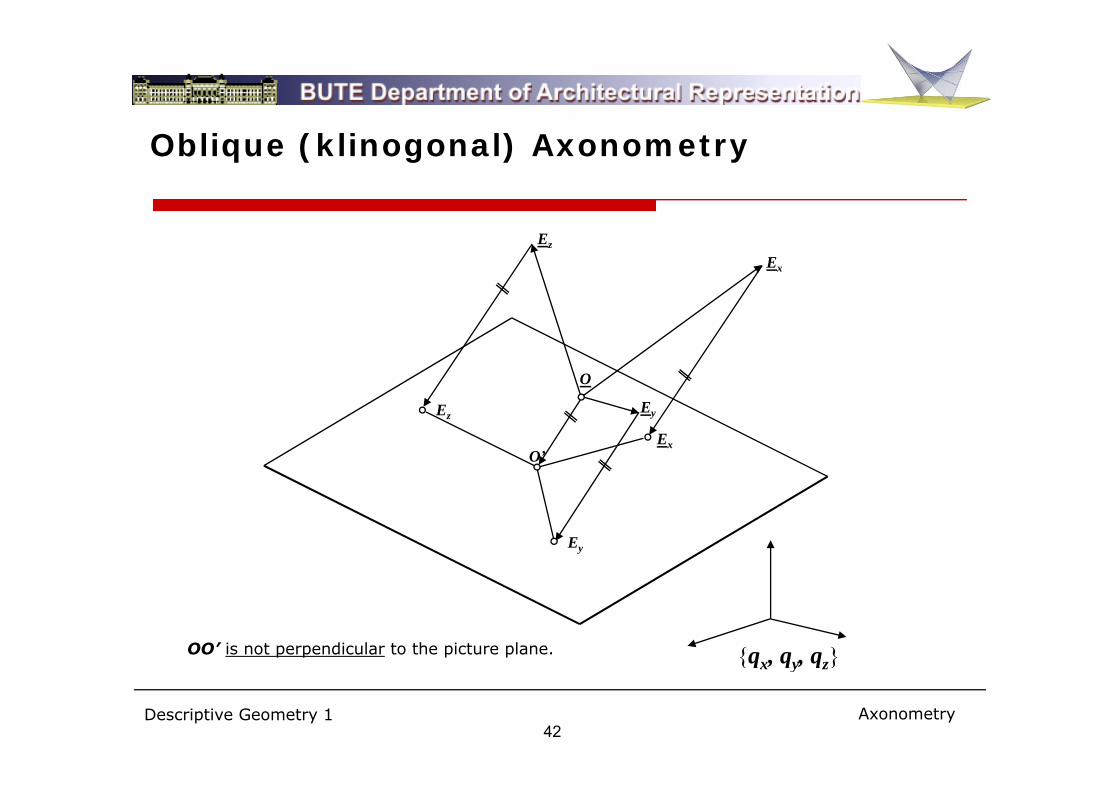
Oblique (klinogonal) Axonometry
Ez
Ex
O
Ex
Ez
O’
Ey
Ey
OO’ is not perpendicular to the picture plane. {qx, qy, qz}
Descriptive Geometry 142
{qx, qy, qz}
Axonometry

Izometry, Technical Axonometry
Izometry Technical axonometry
z z
x8 8
7
1120° 120°
120°
qx = qy = qz =1
xy
y qx = qz =1, qy = ½
Descriptive Geometry 143
Axonometry

Cavalier, Bird’s-eye View, Worm’s-eye View
Frontal Axonometry Bird’s eye view (top view)Military axonometry
z
Worm’s eye view (bottom view)
z
xz
y
x
yy
Image plane: [xz]
if q = 1 : cavalier axonometry
y
Image plane: [xy] qx = qy = 1
if q = 1: military axonometry
x
Image plane: [xy]qx = qy = 1
Descriptive Geometry 144
if qy = 1 : cavalier axonometry if qz = 1: military axonometry qx qy
Axonometry

Frontal Axonometry, Shadow
AA
Descriptive Geometry 145
(A)
Axonometry

Military Axonometry
d
Descriptive Geometry 146
www.xanadu.cz http://www.fotosearch.com/NGF001/57478808/
Axonometry

Cast Shadow in Orthogonal Axonometry
A*
f
A
K*
fDodecahedron, top view and heights
K
ftop view and heights
f’x12
K’(A) (O)
Descriptive Geometry 147
Axonometry

Projected Shadow
A*
X*J*
I*
AC*
J
IH*
K*
B
B* X
Y*
CJ
HK
BCD* D Y
D
Descriptive Geometry 148
Axonometry

Representation of Circle (Multi-view)
”” 6” v”
h” 1”
3” 6”
8”10” 1. The major axes lie on first and second principal lines
h’ and v” respectively.
2. The length of major axes 1’2’ and 5”6” is equal to O”
2”
5”
7”9”
the diameter of circle (true length).
3. The length of a minor axis is constructible from the major axis and a point, as plane geometric construction. (See construction of 8”)
x1,2
2’
4”5
7’
1”
6”
aa
b8”
v’
4’
5’6’
10’
4 Th l f d i h i 9 d 10 b
1”
5”
b
O’
1’
3’
6
8’
9’4. The left and right extreme points 9 and 10 can be
found as points of ellipse with vertical tangents, by means of orthogonal axial affinity.
5. The tangents at the points mentioned above are parallel to the proper diameters
O
Descriptive Geometry 149
h’8 parallel to the proper diameters.
Representation of circle

Representation of Circle (Orthogonal Axonometry)
z1. The major axes of ellipses are perpendicular to
the coordinate axes.
2. The minor axes are coinciding lines with the coordinate axescoordinate axes.
3. The fundamental method of constructions is the orthogonal axial affinity.
Ooz
x
O
(y)
zo
x
y
(y)
O (x)
yy x
(O)
Descriptive Geometry 150
Representation of circle

Representation of Circle (Oblique Axonometry)
z1. The fundamental method of
constructions is the oblique axial affinity.
2 The e n be on t ted b R t ’ 2. The axes can be constructed by Rytz’ method. The ellipse is determined by a pair of conjugated diameters; find the major and minor axes.
xyoQ*
LYo
y
Q
P-90°M
Yy
(y)
ON
(Y)
Descriptive Geometry 151
(y)
Representation of circle

Axonometry vs. Perspective
Descriptive Geometry 152
Perspective

Vanishing Point, Vanishing Line
Vt∞
Vt
ishin
g lin
e
ishin
g lin
e
Vl
Vr Vl Vrvanishing line horizon vanishing line horizon
van
van
Vl r
A set of parallel lines in the scene is projected onto a set of lines in the image that meet in a common point. This point of intersection is called the vanishing point. A vanishing point can be a finite (real) point or an infinite (ideal) point on the image plane. Vanishing points which lie on the same plane in the
Descriptive Geometry 153
p ( ) p g p g p pscene define a line in the image, the so-called the vanishing line.
Perspective

Basics of Perspective with Vertical Image Plane
i l
CF
hplane of horizon
FV
plane of horizon
Principal point
l
P
image planerotated ground plane
d l
(C)
rotated center
C
h
l
V
image plane
aground planeA=(A) P
aCa
VF
P
h(P)
ground plane
(C)
P
aA=(A)
Descriptive Geometry 154
( )
Perspective

Perspective Collineation, Perspective Mapping
A ti lli ti i d t i d A perspective collineation is determined
by the center C, axis a and the
vanishing line v.
To the square P’ Q’ R’ S’=S we can
V1 V2V3 v
P’l
l’Q’
To the square P , Q , R , S =S, we can
find the quadrilateral PQRS at the
mapping Π’ Y Π.a
P
lR’
S’=S
QR
When the ground plane is rotated into
the picture plane, the two systems of
points and lines are related by central-
CV1 V2V3 h
(l)(Q)(P) axial collineation. This perspective
collineation is determined by the
rotated center (C), axis a and the P
l
(l)(Q)
(R)Q
R
horizon h (vanishing line).
To the square (P), (Q), (R), (S)=S, we
can find the quadrilateral PQRS at the
(C)
aS’=S
Descriptive Geometry 155
mapping (Π) Y Π.(C)
Perspective

Heights in Perspective
ing lin
eTrue height can be measured in the image plane
vanis
hi
vanishing line h
atrue height
Descriptive Geometry 156
Perspective

Representation of Circle (Perspective)
h F
(B)
V(P)
In vertical planeIn the ground plane
(O)
O(K)B (b)b (M)
a
O(K)
K
Q=(Q)
d P
M
A=(A) [M] [P]
(C)
K: midpoint of AB center of the ellipsed
dist((Q),(P)) = dist((A),(B))M: midpoint of PQ
( ) i hi li f d l
K: midpoint of AB, center of the ellipse
O: image of center of circle
d = dist( (v), a) = dist( (C), h)
d
Descriptive Geometry 157
(v) vanishing line of ground plane
Perspective

Cylinder and Cone in Perspective
Axonometric sketch
Ch C
h
h C
aCa
a
r
r
Descriptive Geometry 158
Perspective

Shadow in Perspective
shadow vanishing pointhorizon If’
light vanishing pointIf
Descriptive Geometry 159
light vanishing pointhttp://www.math.ubc.ca/~cass/courses/m309-03a/m309-projects/endersby/Antisolarpoint.html
If
Perspective
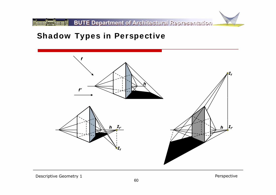
Shadow Types in Perspective
If
f
f
f’
h
If’ If’hh
If
Descriptive Geometry 160
Perspective

Perspective with Slanting Picture Plane
h
C F
H H
C
F[C]F
Vz
Vz
Descriptive Geometry 161
Perspective

Constructions with Slanting Picture Plane
Rotation of the ground plane Rotation of a vertical line
h
hH
Hl
(l)
(P) V[C]F
h
[C]F
H(P)
P
N
V
(p)a
a
(C)N
p
Vz
Descriptive Geometry 162
Perspective

Perspective with Slanting Picture Plane
Descriptive Geometry 163
Perspective