basic concepts of descriptive · pdf file2 basic concepts of descriptive geometry from this...
TRANSCRIPT
2 Basic Concepts of Descriptive Geometry
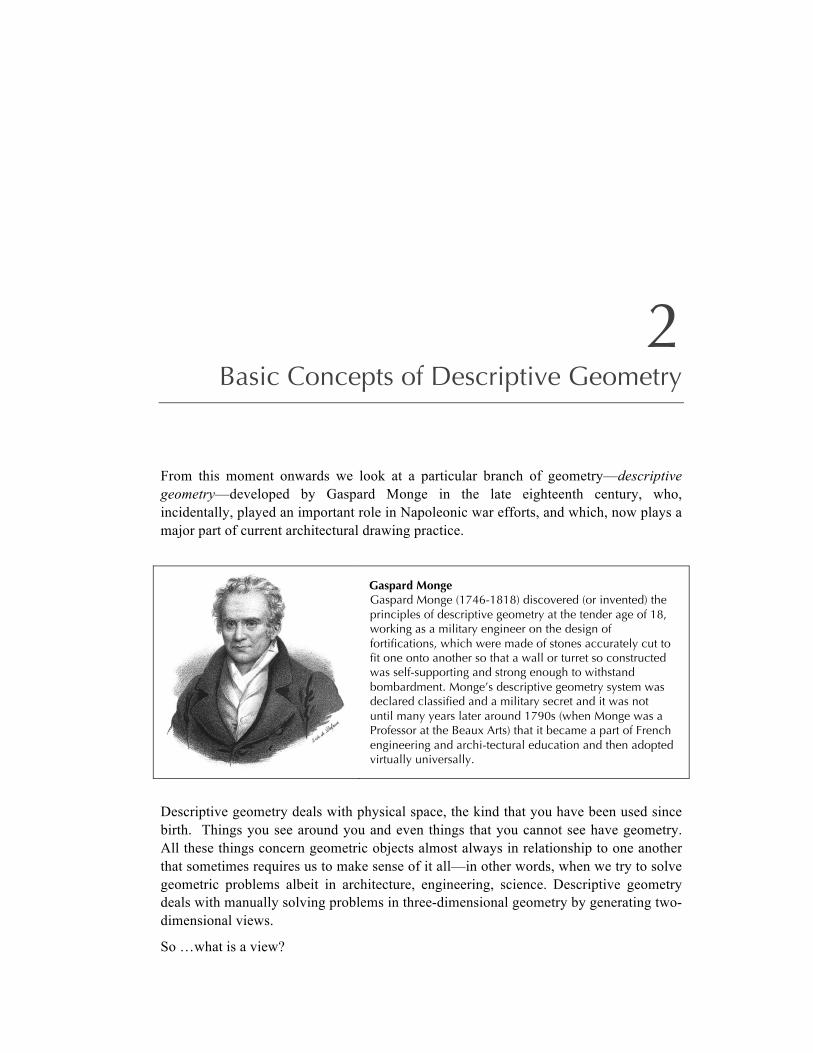
From this moment onwards we look at a particular branch of geometry—descriptive geometry—developed by Gaspard Monge in the late eighteenth century, who, incidentally, played an important role in Napoleonic war efforts, and which, now plays a major part of current architectural drawing practice.
Gaspard Monge Gaspard Monge (1746-1818) discovered (or invented) the principles of descriptive geometry at the tender age of 18, working as a military engineer on the design of fortifications, which were made of stones accurately cut to fit one onto another so that a wall or turret so constructed was self-supporting and strong enough to withstand bombardment. Monge’s descriptive geometry system was declared classified and a military secret and it was not until many years later around 1790s (when Monge was a Professor at the Beaux Arts) that it became a part of French engineering and archi-tectural education and then adopted virtually universally.
Descriptive geometry deals with physical space, the kind that you have been used since birth. Things you see around you and even things that you cannot see have geometry. All these things concern geometric objects almost always in relationship to one another that sometimes requires us to make sense of it all—in other words, when we try to solve geometric problems albeit in architecture, engineering, science. Descriptive geometry deals with manually solving problems in three-dimensional geometry by generating two-dimensional views.
So …what is a view?
52
2.1 VIEWS
A view is a two dimensional picture of geometric objects.
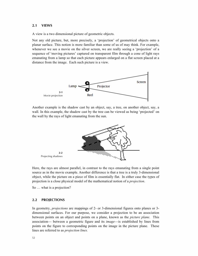
Not any old picture, but, more precisely, a ‘projection’ of geometrical objects onto a planar surface. This notion is more familiar than some of us of may think. For example, whenever we see a movie on the silver screen, we are really seeing a ‘projection’ of a sequence of ‘moving pictures’ captured on transparent film through a cone of light rays emanating from a lamp so that each picture appears enlarged on a flat screen placed at a distance from the image. Each such picture is a view.
2-1 Movie projection
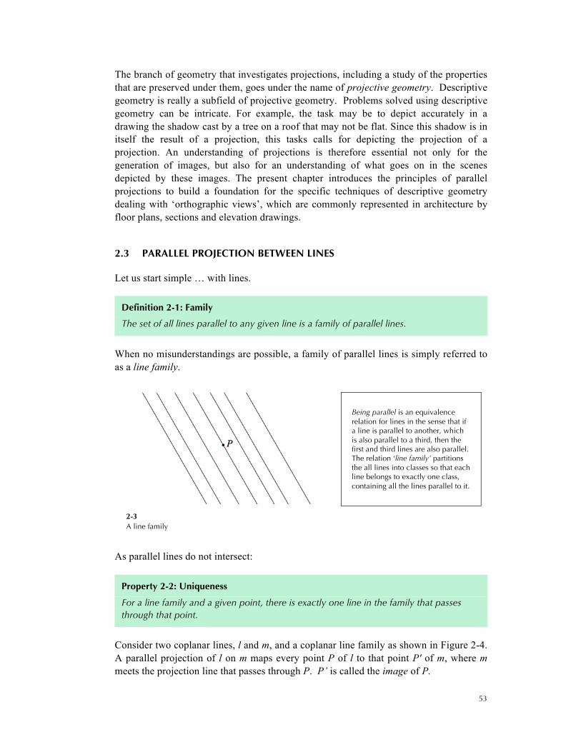
Another example is the shadow cast by an object, say, a tree, on another object, say, a wall. In this example, the shadow cast by the tree can be viewed as being ‘projected’ on the wall by the rays of light emanating from the sun.
2-2 Projecting shadows
Here, the rays are almost parallel, in contrast to the rays emanating from a single point source as in the movie example. Another difference is that a tree is a truly 3-dimensional object, while the picture on a piece of film is essentially flat. In either case the types of projection is a close physical model of the mathematical notion of a projection.
So … what is a projection?
2.2 PROJECTIONS
In geometry, projections are mappings of 2- or 3-dimensional figures onto planes or 3-dimensional surfaces. For our purpose, we consider a projection to be an association between points on an object and points on a plane, known as the picture plane. This association— between a geometric figure and its image—is established by lines from points on the figure to corresponding points on the image in the picture plane. These lines are referred to as projection lines.
53
The branch of geometry that investigates projections, including a study of the properties that are preserved under them, goes under the name of projective geometry. Descriptive geometry is really a subfield of projective geometry. Problems solved using descriptive geometry can be intricate. For example, the task may be to depict accurately in a drawing the shadow cast by a tree on a roof that may not be flat. Since this shadow is in itself the result of a projection, this tasks calls for depicting the projection of a projection. An understanding of projections is therefore essential not only for the generation of images, but also for an understanding of what goes on in the scenes depicted by these images. The present chapter introduces the principles of parallel projections to build a foundation for the specific techniques of descriptive geometry dealing with ‘orthographic views’, which are commonly represented in architecture by floor plans, sections and elevation drawings.
2.3 PARALLEL PROJECTION BETWEEN LINES
Let us start simple … with lines.
Definition 2-1: Family
The set of all lines parallel to any given line is a family of parallel lines.
When no misunderstandings are possible, a family of parallel lines is simply referred to as a line family.
Being parallel is an equivalence relation for lines in the sense that if a line is parallel to another, which is also parallel to a third, then the first and third lines are also parallel. The relation ‘line family’ partitions the all lines into classes so that each line belongs to exactly one class, containing all the lines parallel to it.
2-3 A line family
As parallel lines do not intersect:
Property 2-2: Uniqueness
For a line family and a given point, there is exactly one line in the family that passes through that point.
Consider two coplanar lines, l and m, and a coplanar line family as shown in Figure 2-4. A parallel projection of l on m maps every point P of l to that point P' of m, where m meets the projection line that passes through P. P’ is called the image of P.

54
2-4 Projection between lines
This projection establishes a one-to-one correspondence between the points on l and the points on m. We call this simply a projection between lines l and m.
From elementary geometry, whenever parallel lines are intersected by a traversal (a line not parallel to the line), opposite interior angles formed at the intersection points are identical in measure (congruent).
2-5 Opposite angles along a transversal are identical
Consider now a parallel projection of a line l on a line m and two distinct points, A and B, on l and their images on m, A’ and B’. There are two cases to consider:
• l and m are parallel, in which case polygon ABB'A' is a parallelogram and consequently, AA' = BB'; that is, the projection preserves distances.
• l and m intersect at a point, say P. In this case, P is fixed and triangle !PAA' is similar to !PBB'. Consequently, !"!
!" = !"!
!" = !"!
!" = k
That is, the projection multiplies distances by a constant factor k.
55
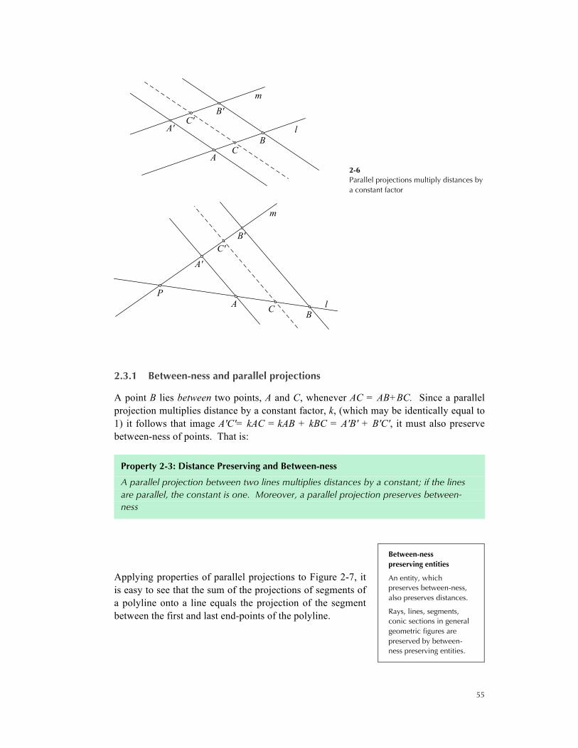
2-6 Parallel projections multiply distances by a constant factor
2.3.1 Between-ness and parallel projections
A point B lies between two points, A and C, whenever AC = AB+BC. Since a parallel projection multiplies distance by a constant factor, k, (which may be identically equal to 1) it follows that image A'C'= kAC = kAB + kBC = A'B' + B'C', it must also preserve between-ness of points. That is:
Property 2-3: Distance Preserving and Between-ness
A parallel projection between two lines multiplies distances by a constant; if the lines are parallel, the constant is one. Moreover, a parallel projection preserves between-ness
Applying properties of parallel projections to Figure 2-7, it is easy to see that the sum of the projections of segments of a polyline onto a line equals the projection of the segment between the first and last end-points of the polyline.
Between-ness preserving entities
An entity, which preserves between-ness, also preserves distances.
Rays, lines, segments, conic sections in general geometric figures are preserved by between-ness preserving entities.
m
l
CA
A'B
B'C'
m
lC
PA
A'
B
B'C'

56
2-7 Sum of the projections of segments of a polyline onto a line equals the projection of the segment between the first and last end-points of the polyline
Construction 2-1 Dividing a given segment of arbitrary length in a given ratio
We are going to revisit the constructible constructions albeit via a variation. Suppose 𝐴𝐵 is a given segment and suppose we are given a ratio, say m:n, where m and n are integers. From one of the end points, say A, draw a ray, r. Mark m units on a convenient unit of measure from A on the ray. Let the mark be M. From repeat this step with a measure of n units. Call this mark N. Draw a line –M– parallel to –NB– and let it meet 𝐴𝐵 at M', which divides the segment into the required ratio.
2-8 Dividing a segment into two segments in a given ratio
This construction clearly employs a parallel projection from r to 𝐴𝐵. Note that construction also works if 𝐴𝐵 is to be extended in the ratio m:n; in this case, we draw a line –N– parallel to –MB– and let it meet –AB– at N’. Then, AN' extends AB in the required ratio.
line
projections
polyline

57
EXAMPLE: Dividing and extending segments
The above construction also works for any number of divisions or extensions by integer ratios and for any combination of divisions and extensions. For example, if AB is to be divided into three segments with ratios 4:2:3 and extended by two segments in the ratio 2:4, we mark off points on r after 4, 6 (= 4+2), 9 (= 4+2+3), 11(= 9+2) and 15 (= 9+2+4) units and draw the line l through the point at mark 9; the desired points on AB or its extension are the projections of the marks on r by lines parallel to l. This is illustrated in Figure 2-9.
2-9 Dividing and extending a segment into an arbitrary number of given ratios
The reader may notice the relationship to constructions [1.16], which is interpreted in terms of similarity between lengths, whereas this construction is interpreted in terms of parallel projections.
2.1.1 Parallel projections between planes
We can now extend the notion of a parallel projection to planes in space.
Definition 2-4: Parallel Projection between Planes
Let p and p' be two distinct planes and ƒ a line family not parallel to either plane.
A parallel projection of p onto p’ maps every point P of p onto point P' of p' where p' meets the line in ƒ that passes through P.
Because there is exactly one line in f that passes through P, this type of mapping establishes a 1-1 correspondence between points of p and p’, and we often, simply, call this a projection between the points of the planes.
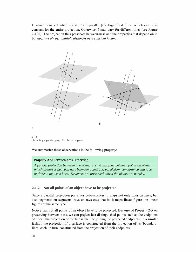
Consider a line l on p. The lines in ƒ that pass through l form a plane distinct from p’ that intersects p’ at a line l’ which is the image of l under the projection. It thus maps lines on lines. Furthermore, l’ is the image of l under a coplanar parallel projection. Because a parallel projection between two lines multiplies distances by a constant factor
58
k, which equals 1 when p and p’ are parallel (see Figure 2-10i), in which case it is constant for the entire projection. Otherwise, k may vary for different lines (see Figure 2-10ii). The projection thus preserves between-ness and the properties that depend on it, but does not always multiply distances by a constant factor.
i
ii
2-10 Illustrating a parallel projection between planes
We summarize these observations in the following property:
Property 2-5: Between-ness Preserving
A parallel projection between two planes is a 1-1 mapping between points on planes, which preserves between-ness between points and parallelism, concurrence and ratio of division between lines. Distances are preserved only if the planes are parallel.
2.1.2 Not all points of an object have to be projected
Since a parallel projection preserves between-ness, it maps not only lines on lines, but also segments on segments, rays on rays etc.; that is, it maps linear figures on linear figures of the same type.
Notice that not all points of an object have to be projected. Because of Property 2-5 on preserving between-ness, we can project just distinguished points such as the endpoints of lines. The projection of the line is the line joining the projected endpoints. In a similar fashion the projection of a surface is constructed from the projection of its ‘boundary’ lines, each, in turn, constructed from the projection of their endpoints.
f
p'
p
l'
l
f
ap'
p
l'
l

59
If we apply this to a piece of architecture, we see that a projection of a planar facade on a plane parallel to it shows all features of the facade in true size (see Figure 2-11). This fact explains why elevations are so important in building design; plans and sections are important for similar reasons. But note also in the figure that the roof, which is not projected on a plane parallel to it, appears in the projection not in true size. The next section will get back to the role of parallel projections in architecture in greater detail.
2-11 Orthographic projection of a facade
The method works even for curved objects. In fact, we can show (although we do not do so here) the following property, which will be important for subsequent chapters:
Property 2-6: Type Preserving
A parallel projection between two planes maps parabolas onto parabolas, hyperbolas onto hyperbolas, circles or ellipses onto circles or ellipses, and, more generally, curves of degree n onto curves of degree n.
The ‘boundary’ of the surface corresponds to points on the object at which the projection lines are tangential to the surface of the object.
2.1.3 Parallel projections of general figures
The notion of a parallel projection that underlies Definition 2-4 can be extended to projections of general 3-dimensional objects by means of a line family on a plane, even a non-planar surface in space. For example, to model geometrically the shadow cast by a cylindrical tower on a domed roof under parallel light rays like the ones generated by the sun, one would use a parallel projection of a cylinder on part of a sphere under a line family whose lines are parallel to the rays of the sun.
More straightforward is the projection of a spatial figure on a plane. The image created on that plane can be viewed as a 2-dimensional representation of the figure; descriptive
60
geometry deals with precisely the generation of such images. Since objects of interest in architecture and related fields are often composed of linear shapes, such images can often be pieced together by a series of parallel projections between planes as defined—Figure 2-11 illustrates this as well.
However, that scenes thus depicted may involve images of more complicated projections such as the shadows described above. The handling of ‘shades and shadows’ and similar projections constitutes indeed a special subfield of descriptive geometry, which we will consider later in the course.
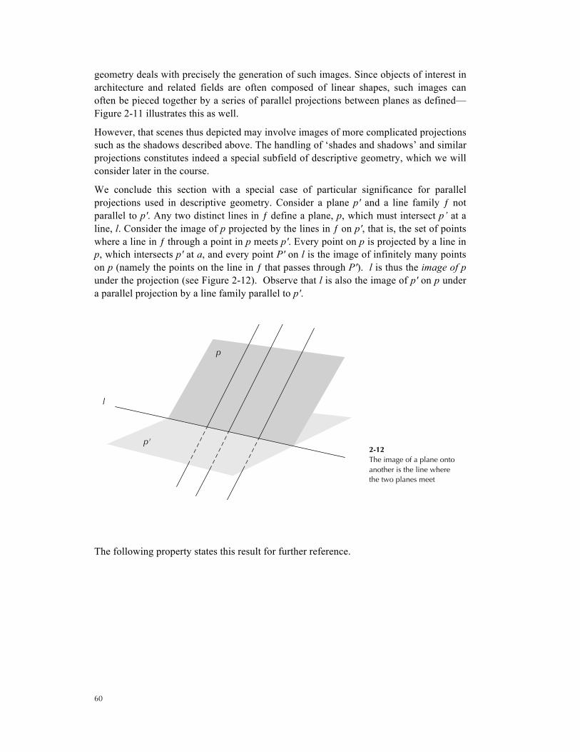
We conclude this section with a special case of particular significance for parallel projections used in descriptive geometry. Consider a plane p' and a line family ƒ not parallel to p'. Any two distinct lines in ƒ define a plane, p, which must intersect p’ at a line, l. Consider the image of p projected by the lines in ƒ on p', that is, the set of points where a line in ƒ through a point in p meets p'. Every point on p is projected by a line in p, which intersects p' at a, and every point P' on l is the image of infinitely many points on p (namely the points on the line in ƒ that passes through P'). l is thus the image of p under the projection (see Figure 2-12). Observe that l is also the image of p' on p under a parallel projection by a line family parallel to p'.
2-12 The image of a plane onto another is the line where the two planes meet
The following property states this result for further reference.
p
p'
l
61
Property 2-7: Image of plane onto another
If ƒ is a line family, p a plane parallel to ƒ and p' a plane not parallel to ƒ, the image of p projected on p' by ƒ is the line l where p and p' meet.
Conversely, the image of p’ projected on p by a line family is the line l where p and p' meet.
2.4 ORTHOGRAPHIC VIEWS
When you draw a floor plan, section or elevation of a building, you are (consciously or unconsciously) using a special form of parallel projection, which is introduced in the following definition:
Definition 2-8: Orthographic Projection and Views
Let ƒ be a family of lines and p a plane not parallel to ƒ. The parallel projection of a figure on p by ƒ is an orthographic projection if the lines in ƒ are normal (perpendicular) to p.
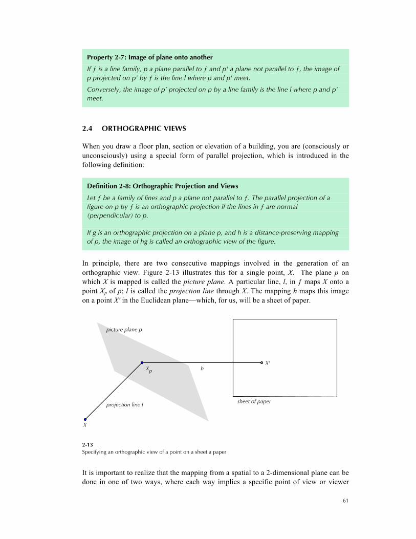
If g is an orthographic projection on a plane p, and h is a distance-preserving mapping of p, the image of hg is called an orthographic view of the figure.
In principle, there are two consecutive mappings involved in the generation of an orthographic view. Figure 2-13 illustrates this for a single point, X. The plane p on which X is mapped is called the picture plane. A particular line, l, in ƒ maps X onto a point Xp of p; l is called the projection line through X. The mapping h maps this image on a point X' in the Euclidean plane—which, for us, will be a sheet of paper.
2-13 Specifying an orthographic view of a point on a sheet a paper
It is important to realize that the mapping from a spatial to a 2-dimensional plane can be done in one of two ways, where each way implies a specific point of view or viewer
projection line l
h
picture plane p
sheet of paper
Xp
X
X'
62
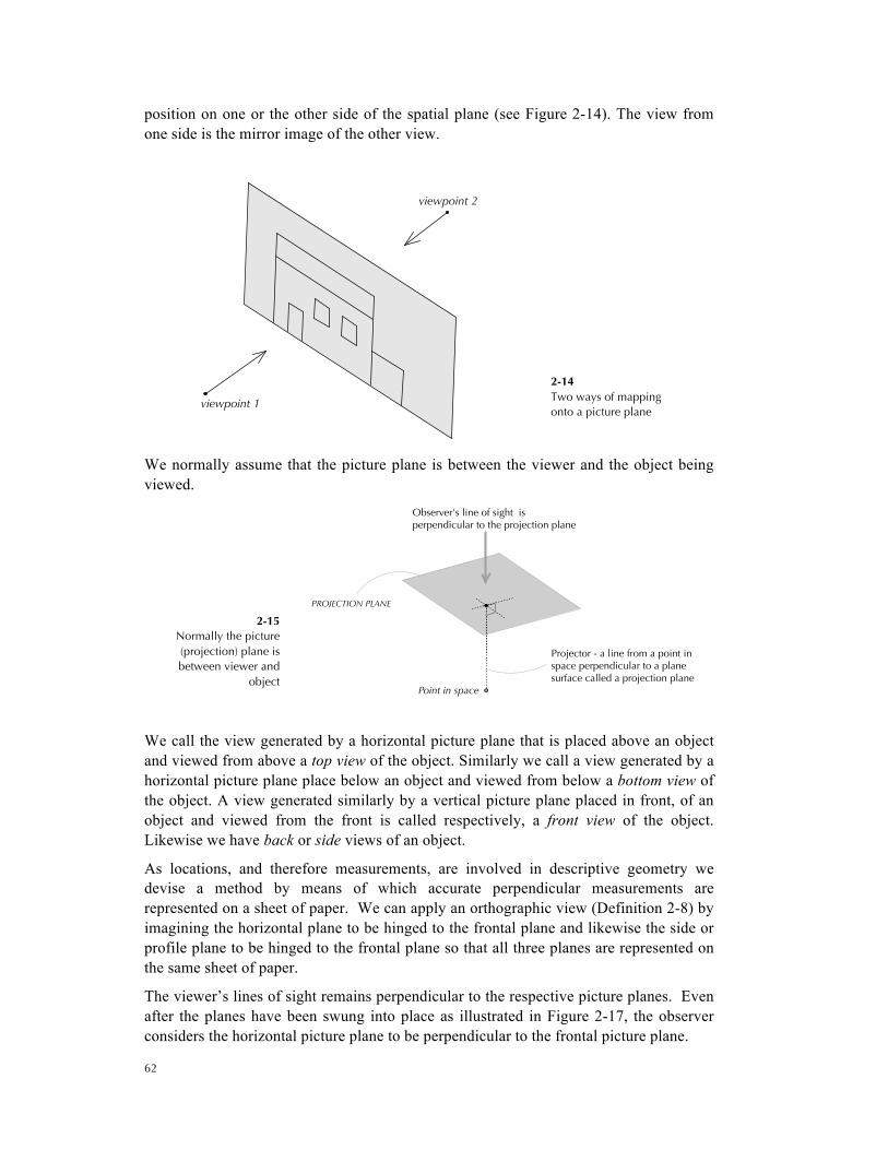
position on one or the other side of the spatial plane (see Figure 2-14). The view from one side is the mirror image of the other view.
2-14 Two ways of mapping onto a picture plane
We normally assume that the picture plane is between the viewer and the object being viewed.
2-15 Normally the picture (projection) plane is between viewer and
object
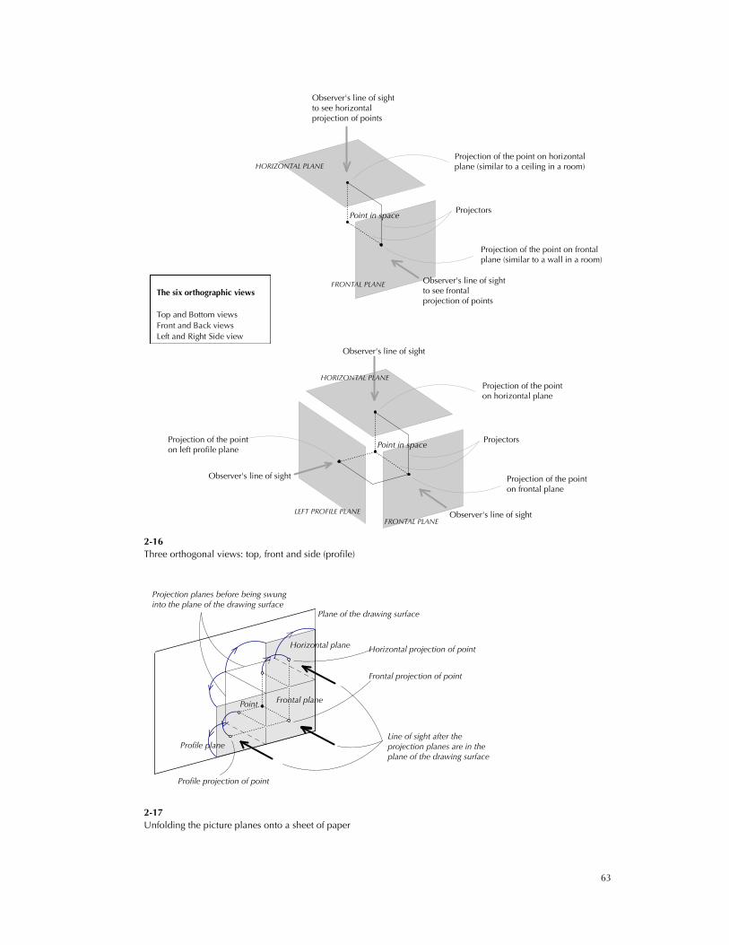
We call the view generated by a horizontal picture plane that is placed above an object and viewed from above a top view of the object. Similarly we call a view generated by a horizontal picture plane place below an object and viewed from below a bottom view of the object. A view generated similarly by a vertical picture plane placed in front, of an object and viewed from the front is called respectively, a front view of the object. Likewise we have back or side views of an object.
As locations, and therefore measurements, are involved in descriptive geometry we devise a method by means of which accurate perpendicular measurements are represented on a sheet of paper. We can apply an orthographic view (Definition 2-8) by imagining the horizontal plane to be hinged to the frontal plane and likewise the side or profile plane to be hinged to the frontal plane so that all three planes are represented on the same sheet of paper.
The viewer’s lines of sight remains perpendicular to the respective picture planes. Even after the planes have been swung into place as illustrated in Figure 2-17, the observer considers the horizontal picture plane to be perpendicular to the frontal picture plane.
viewpoint 1
viewpoint 2
PROJECTION PLANE
Projector - a line from a point inspace perpendicular to a planesurface called a projection plane
Observer's line of sight isperpendicular to the projection plane
Point in space
63
2-16 Three orthogonal views: top, front and side (profile)
2-17 Unfolding the picture planes onto a sheet of paper
Observer's line of sightto see frontalprojection of points
Projection of the point on frontalplane (similar to a wall in a room)
Projection of the point on horizontalplane (similar to a ceiling in a room)
Projectors
Observer's line of sight to see horizontalprojection of points
FRONTAL PLANE
HORIZONTAL PLANE
Point in space
Observer's line of sight
Observer's line of sight
Projection of the pointon frontal plane
Projection of the pointon horizontal plane
Projection of the pointon left profile plane
Projectors
Observer's line of sight
LEFT PROFILE PLANEFRONTAL PLANE
HORIZONTAL PLANE
Point in space
Horizontal plane
Frontal projection of point
Profile projection of point
Horizontal projection of point
Line of sight after theprojection planes are in theplane of the drawing surface
Projection planes before being swunginto the plane of the drawing surface
Profile plane
Frontal plane
Plane of the drawing surface
Point
The six orthographic views Top and Bottom views Front and Back views Left and Right Side view
64
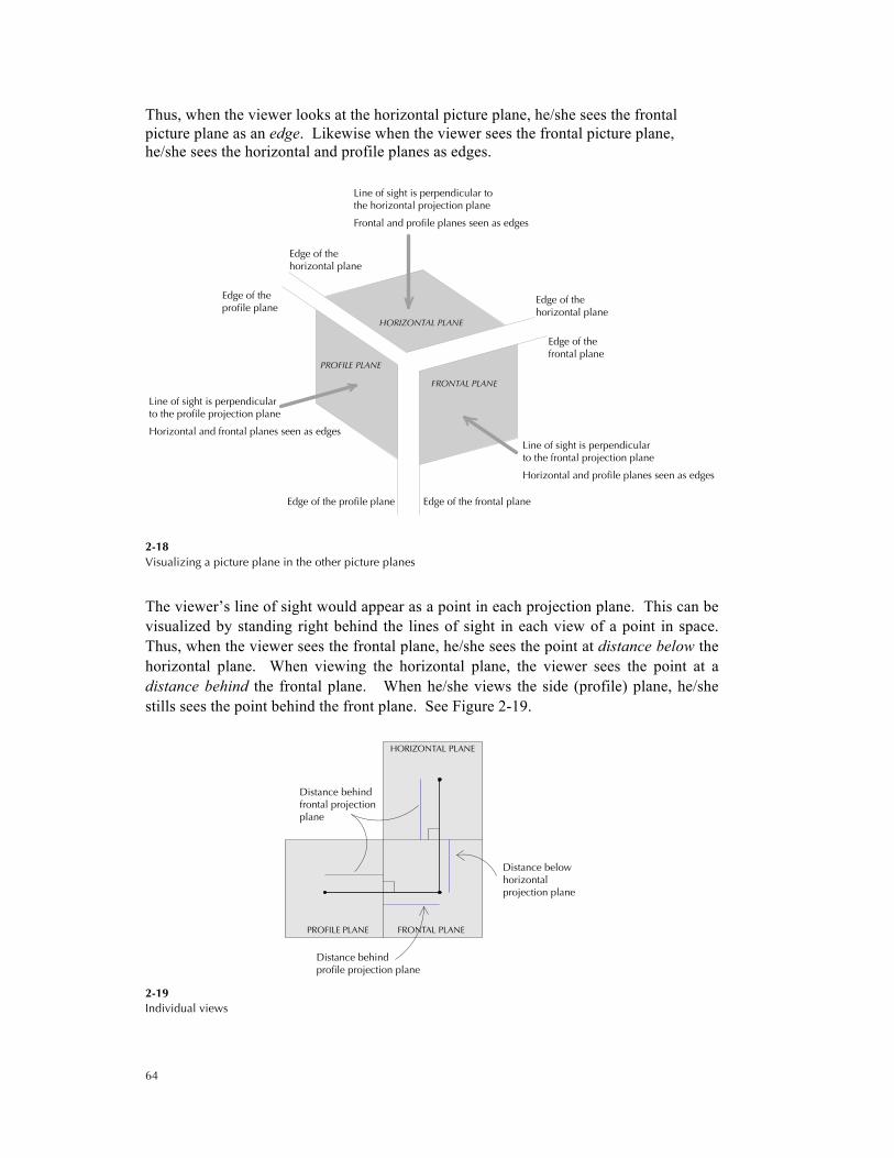
Thus, when the viewer looks at the horizontal picture plane, he/she sees the frontal picture plane as an edge. Likewise when the viewer sees the frontal picture plane, he/she sees the horizontal and profile planes as edges.
2-18 Visualizing a picture plane in the other picture planes
The viewer’s line of sight would appear as a point in each projection plane. This can be visualized by standing right behind the lines of sight in each view of a point in space. Thus, when the viewer sees the frontal plane, he/she sees the point at distance below the horizontal plane. When viewing the horizontal plane, the viewer sees the point at a distance behind the frontal plane. When he/she views the side (profile) plane, he/she stills sees the point behind the front plane. See Figure 2-19.
2-19 Individual views
Horizontal and frontal planes seen as edges
Horizontal and profile planes seen as edges
Frontal and profile planes seen as edges
Edge of theprofile plane
Edge of the profile plane Edge of the frontal plane
Line of sight is perpendicularto the profile projection plane
Line of sight is perpendicularto the frontal projection plane
Edge of thefrontal plane
Edge of thehorizontal plane
Edge of thehorizontal plane
Line of sight is perpendicular tothe horizontal projection plane
PROFILE PLANE
FRONTAL PLANE
HORIZONTAL PLANE
HORIZONTAL PLANE
PROFILE PLANE FRONTAL PLANE
Distance behindfrontal projectionplane
Distance belowhorizontalprojection plane
Distance behindprofile projection plane
65
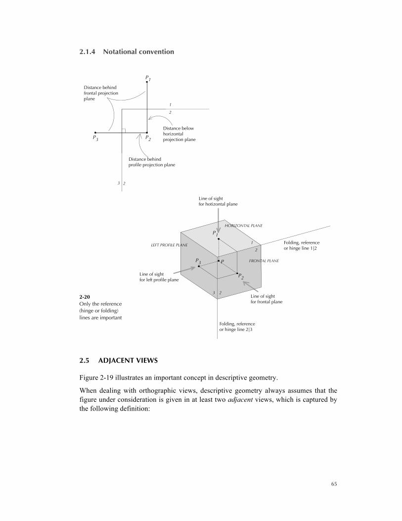
2.1.4 Notational convention
2-20 Only the reference (hinge or folding) lines are important
2.5 ADJACENT VIEWS
Figure 2-19 illustrates an important concept in descriptive geometry.
When dealing with orthographic views, descriptive geometry always assumes that the figure under consideration is given in at least two adjacent views, which is captured by the following definition:
3 2
2
1
Distance behindfrontal projectionplane
Distance belowhorizontalprojection plane
Distance behindprofile projection plane
P1
P2P3
3 2
2
1 Folding, referenceor hinge line 1|2
Line of sightfor hotizontal plane
Line of sightfor left profile plane
Line of sightfor frontal plane
Folding, referenceor hinge line 2|3
LEFT PROFILE PLANE
FRONTAL PLANE
HORIZONTAL PLANE
P3 P
P1
P2

66
Definition 2-9: Adjacent Views
Two intersecting planes are perpendicular if the line of intersection is the image of one plane in the other plane under an orthographic projection.
Two views obtained from two perpendicular picture planes are called adjacent.
Figure 2-21 illustrates perpendicular planes. In architecture you will find countless examples of adjacent views for instance, plan and elevation, an elevation and a second elevation in a picture plane perpendicular to the one used in the first elevation, an elevation and section with picture planes that have the same relationship with each other etc.
2-21 Perpendicular planes
The line where the picture planes of two adjacent views, t and f, meet is called the folding line between t and f and denoted by t | f. The folding line is the image of each view in the adjacent view. We denote the view of a point or object, X, in a view, t, by Xt. Sometimes views are numbered instead of a letter. The same naming conventions apply.
2-22 A point in two adjacent views
X
Xtop
Xfront
folding line
projectionline
top
front
Xtop
Xfront

67
The folding line is also known as the reference or hinge line
2.1.5 Literal versus normal renderings of orthographic views
A literal rendering of the orthographic view of an object would treat each point of the object equally; for a cylinder, this could result in a drawing like the one shown at the top of Figure 2-23, which depicts the cylinder as an unstructured mass without distinguishing between parts that are more important than others. This is hardly ever done. The normal way of rendering the orthographic view of an object is demonstrated at the bottom of Figure 2-23. The visible outline of the figure is always drawn in its entirety because it separates the figure from the background or from other figures. In addition, such a rendering tends to emphasize important other features; in the example shown, the upper rim of the cylinder is shown in its entirety, including the part that does not lie on the outline; this implies that the upper surface is visible from the particular direction from which the object is viewed, while the bottom is not visible and therefore not shown in its entirety.
2-23 Two renderings of an orthographic view of a cylinder
Orthographic views, in architecture or other fields, are generated for a purpose, and the selection of the features to be shown may vary with that purpose.
In general, one shows, aside from the outline, at least the boundary of each surface that can be seen from the direction of view; hidden boundaries are normally deleted if showing them would confuse the image; otherwise, they are shown with dashed lines (see Figure 2-24) or by similar means that distinguish them from the visible lines.
folding line
f
tXt
Xf

68
2-24 A tetrahedron with a hidden edge
Note also that different parts of an object may lie on the outline in different views. For example, the boundary of the cylinder is delineated in Figure 2-23 by two segments, which correspond to two specific segments on the cylinder’s boundary; two different segments would fall on the outline if we were to shift the direction of view (by choosing a different picture plane).
2.6 ORTHOGRAPHIC VIEWS IN ARCHITECTURE: FLOOR PLANS
Floor plans, sections and elevations are for the most part orthographic views of a building or of portions thereof. When we produce such a drawing, we are often not even aware of the underlying principles because the problems involved can be solved intuitively. But in cases when it is not immediately clear how to draw a certain part of a design, we have to go back to the underlying principles in order to resolve the issue at hand. Take, for example, a floor plan. It shows in the majority of cases the walls and partitions on a floor that separate spaces from each other and the outside and indicates the position and width of doors, windows and other openings, along with other important objects. When the walls and openings are vertical, this can be done without complications because the sides of these objects are on planes perpendicular to the picture plane and project on line segments. But how should we draw the floor plan of an attic under a pitched roof, where the main parts are not vertical? This problem can be resolved when we consider what a floor plan really is.
Definition 2-10: Floor Plan
A floor plan of a building is the top view of a portion of a building below a picture plane cutting horizontally through the building. It shows the parts of the building underneath this plane as seen when we view the picture plane from above.
The solid parts that intersect the picture plane (also called the cutting plane) are the most important features depicted and are shown, normally, in outline; openings appear as gaps in this outline. In order to make such a plan as informative as possible, the height of the picture plane must be chosen carefully; especially, it should cut through as many openings as possible (in practice, some ‘cheating’ may be tolerated here if it increases the clarity of the plan; but in case of doubt, it is advisable to stick to a literal interpretation of this process).

69
Objects such as steps, furniture, floor patterns etc. that are below the cutting plane can be projected into that plane and are then shown as in any other orthographic view. Important features above the cutting plane that are visible from it in reality can also be projected into the cutting plane, possibly with dashed lines to distinguish them from other objects. If the sole purpose of a plan is to show ceiling pattern in this way, the plan is usually called a reflected ceiling plan. Many of these devices are illustrated in the first floor plan shown in Figure 2-25.
2-25 Standard drawings of a house in the Tudor style (Top) Third floor plan; and (Bottom) First floor plan
It is important to understand that all of the projections that come into play in such a drawing use the same family of projection lines normal to the cutting plane (and this
70
family is unique). It is up to the designer to decide which of the many features projected by these lines are actually drawn.
The normal case illustrated by the first floor plan in Figure 2-25 depicts vertical walls, that is, walls perpendicular to the picture plane, whose sides consequently project into lines. This is the single most important feature that makes floor plans so easy to construct.
But consider the third floor plan shown in Figure 2-25. The rooms on this floor are enclosed by vertical walls only up to a certain height above which the underside of the roof becomes the boundary of the room towards the outside (see the section in the same figure). If one understands that a floor plan is an orthographic projection into a horizontal cutting plane, viewed from above, it becomes apparent how this situation can be drawn.
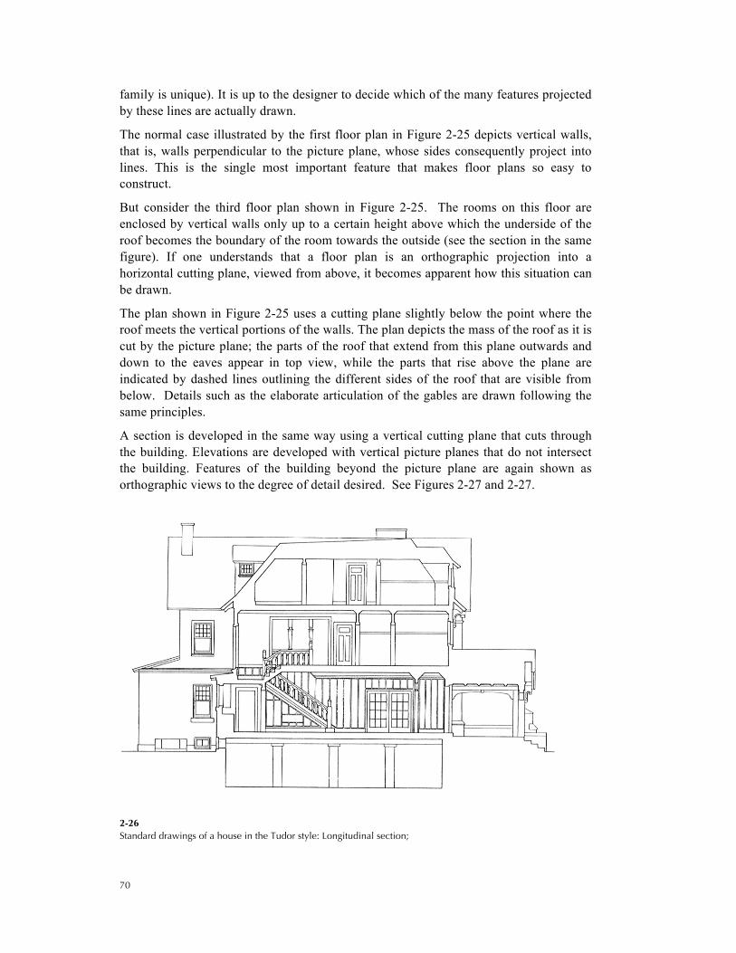
The plan shown in Figure 2-25 uses a cutting plane slightly below the point where the roof meets the vertical portions of the walls. The plan depicts the mass of the roof as it is cut by the picture plane; the parts of the roof that extend from this plane outwards and down to the eaves appear in top view, while the parts that rise above the plane are indicated by dashed lines outlining the different sides of the roof that are visible from below. Details such as the elaborate articulation of the gables are drawn following the same principles.
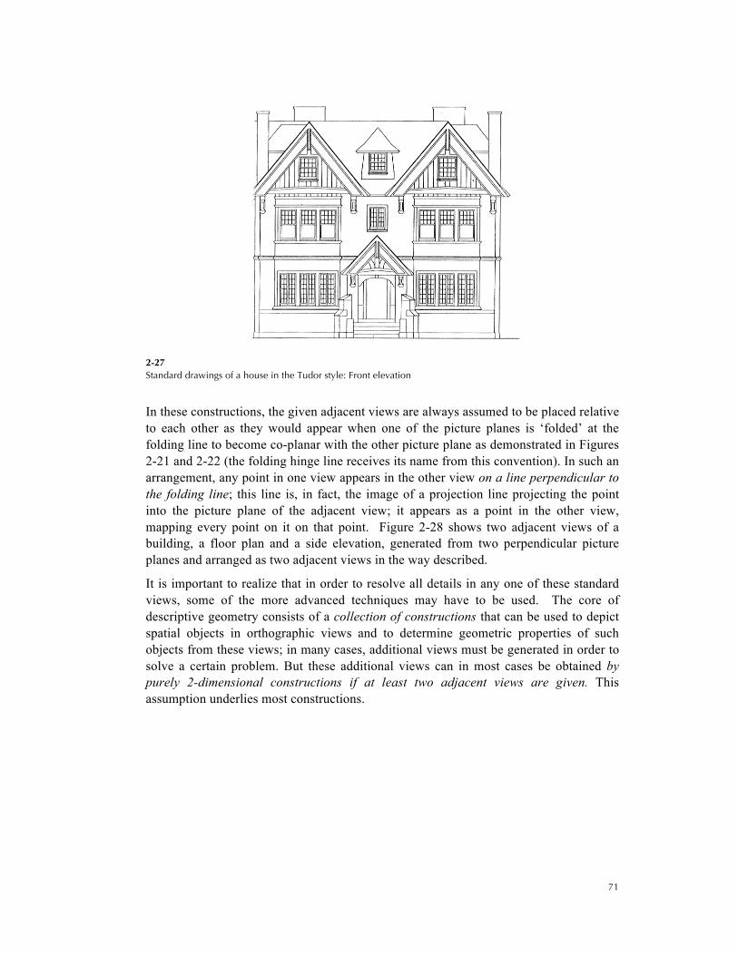
A section is developed in the same way using a vertical cutting plane that cuts through the building. Elevations are developed with vertical picture planes that do not intersect the building. Features of the building beyond the picture plane are again shown as orthographic views to the degree of detail desired. See Figures 2-27 and 2-27.
2-26 Standard drawings of a house in the Tudor style: Longitudinal section;
71
2-27 Standard drawings of a house in the Tudor style: Front elevation
In these constructions, the given adjacent views are always assumed to be placed relative to each other as they would appear when one of the picture planes is ‘folded’ at the folding line to become co-planar with the other picture plane as demonstrated in Figures 2-21 and 2-22 (the folding hinge line receives its name from this convention). In such an arrangement, any point in one view appears in the other view on a line perpendicular to the folding line; this line is, in fact, the image of a projection line projecting the point into the picture plane of the adjacent view; it appears as a point in the other view, mapping every point on it on that point. Figure 2-28 shows two adjacent views of a building, a floor plan and a side elevation, generated from two perpendicular picture planes and arranged as two adjacent views in the way described.
It is important to realize that in order to resolve all details in any one of these standard views, some of the more advanced techniques may have to be used. The core of descriptive geometry consists of a collection of constructions that can be used to depict spatial objects in orthographic views and to determine geometric properties of such objects from these views; in many cases, additional views must be generated in order to solve a certain problem. But these additional views can in most cases be obtained by purely 2-dimensional constructions if at least two adjacent views are given. This assumption underlies most constructions.

72
2-28 Two adjacent views of a building
2.7 VISIBILITY OF LINES
We stated already that a projected object is hardly ever shown in its entirety—that is, by showing every point that belongs to the object—because this would lead to a completely unstructured, incomprehensible image. Most prominent among the features shown are the edges that form the boundary of the object (or of its parts) in the view under consideration. The edges appear as line segments or as curves in the view and are often simply called lines. If all of these lines are displayed, the view is called a wire-frame image. For all but the simplest objects, however, this type of view is still too confusing to be informative. Wire-frame views are therefore usually edited in order to make them more comprehensible. Most commonly, they show which lines are visible or hidden in a particular view. Hidden lines are either dashed (this is usual in many engineering fields) or omitted altogether (this is usual in architectural design).

73
Construction 2-2 Visibility/Intersection Test
Given two lines in two adjacent views, neither line perpendicular to the folding line, that meet at a point, X, in at least one view, t, determine which line is in front of the other (relative to t) at the intersection point.
(Right) The problem 1 Determine which line is in front
(or above) of the other
There are two steps.
1. Draw the projection line a through Xt into view f.
There are two possibilities.
1.1 If the lines meet also at a point on a in view f, the lines truly intersect.
(Right) The lines truly intersect
1.2 Otherwise, the lines do not intersect.
Determine the spatial relation between the lines at Xt from the relative positions of their intersections with a in f: the line that intersects a at a point closer to the
t
f
X
at
f
X

74
folding line than the other line is closer to the picture plane of f at that point; consequently, it is in front of the other line at Xt in t. For example, in the figure below, line l satisfies this condition.
(Right) The lines do not intersect
Project from the (apparent) point of intersection
onto the other view
The same test is applied if the two lines also intersect in view f. See Figure 2-29.
(Left) Relative visibility of two lines
2-29
Intersection test – l is in front in view t and behind in view
The obstructed line is often shown interrupted at the intersection point (when it is visible everywhere except at that point) or dashed (when an entire portion is obstructed) as the example below illustrates.
f
t
X
a
l
l
t
f
X
75
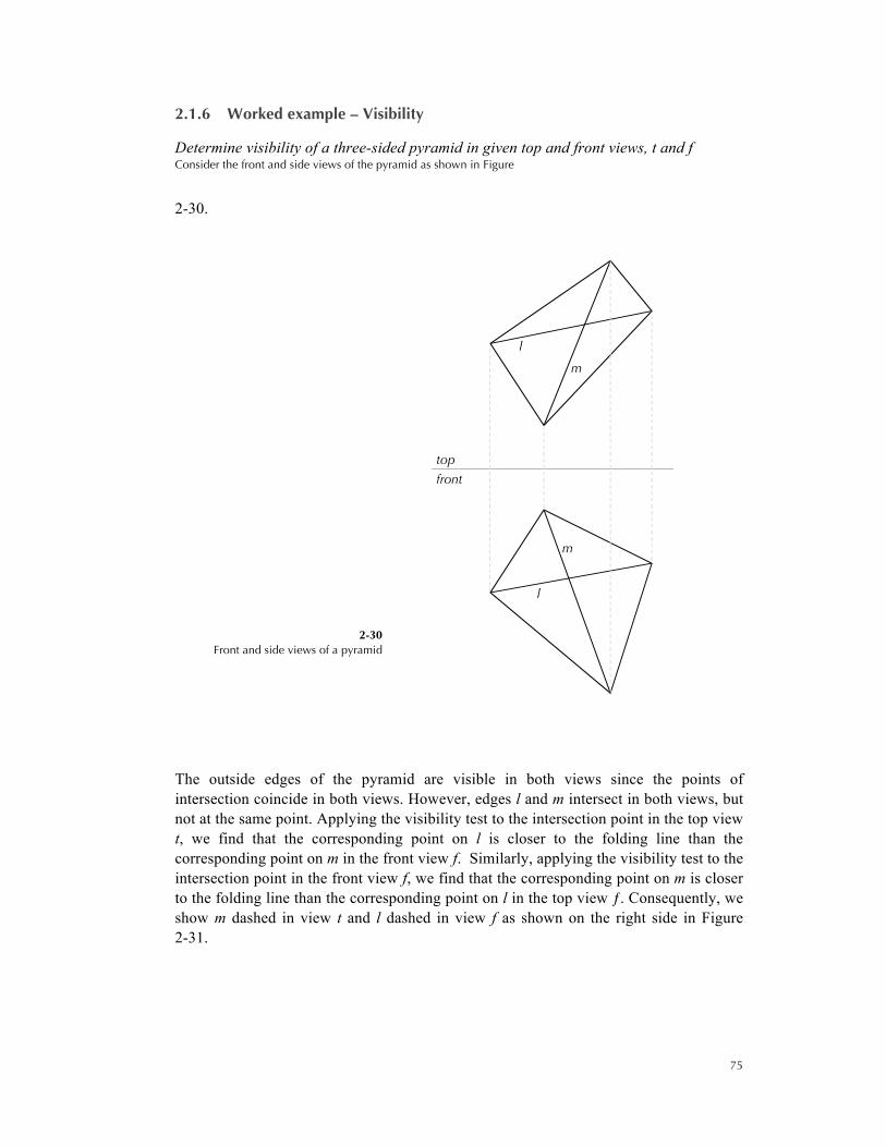
2.1.6 Worked example – Visibility
Determine visibility of a three-sided pyramid in given top and front views, t and f Consider the front and side views of the pyramid as shown in Figure
2-30.
2-30 Front and side views of a pyramid
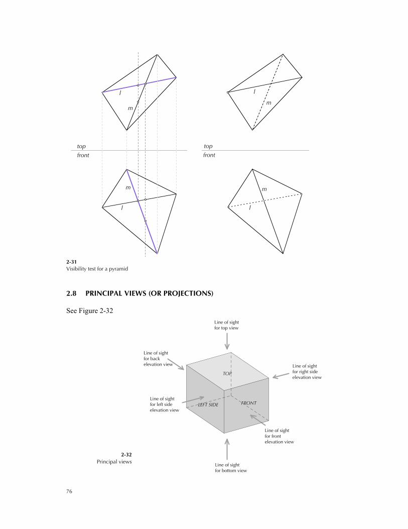
The outside edges of the pyramid are visible in both views since the points of intersection coincide in both views. However, edges l and m intersect in both views, but not at the same point. Applying the visibility test to the intersection point in the top view t, we find that the corresponding point on l is closer to the folding line than the corresponding point on m in the front view f. Similarly, applying the visibility test to the intersection point in the front view f, we find that the corresponding point on m is closer to the folding line than the corresponding point on l in the top view ƒ. Consequently, we show m dashed in view t and l dashed in view f as shown on the right side in Figure 2-31.
m
l
m
l
front
top
76
2-31 Visibility test for a pyramid
2.8 PRINCIPAL VIEWS (OR PROJECTIONS)
See Figure 2-32
2-32 Principal views
m
l
m
l
front
top
m
l
m
l
front
top
Line of sight for top view
Line of sight for bottom view
Line of sightfor left sideelevation view
LEFT SIDE FRONT
TOP
Line of sightfor backelevation view
Line of sightfor frontelevation view
Line of sightfor right sideelevation view
77
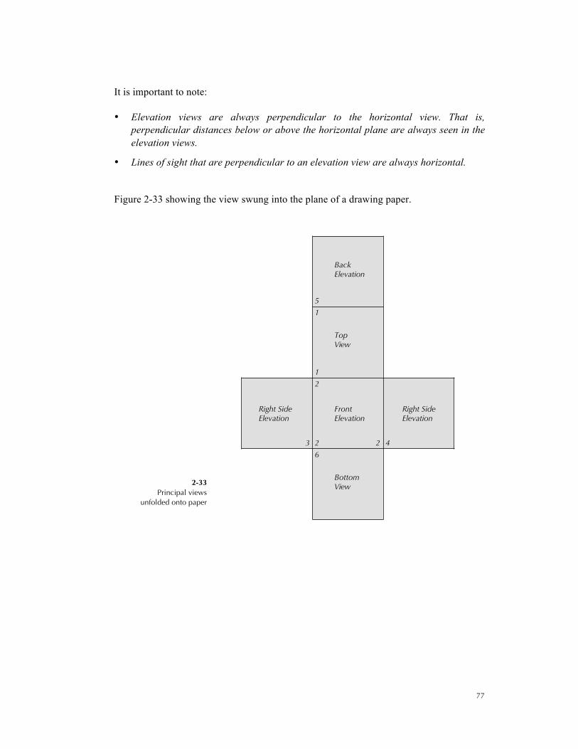
It is important to note:
• Elevation views are always perpendicular to the horizontal view. That is, perpendicular distances below or above the horizontal plane are always seen in the elevation views.
• Lines of sight that are perpendicular to an elevation view are always horizontal.
Figure 2-33 showing the view swung into the plane of a drawing paper.
2-33 Principal views
unfolded onto paper
5
1
6
423 2
2
1
BottomView
TopView
Right SideElevation
Right SideElevation
FrontElevation
BackElevation
78
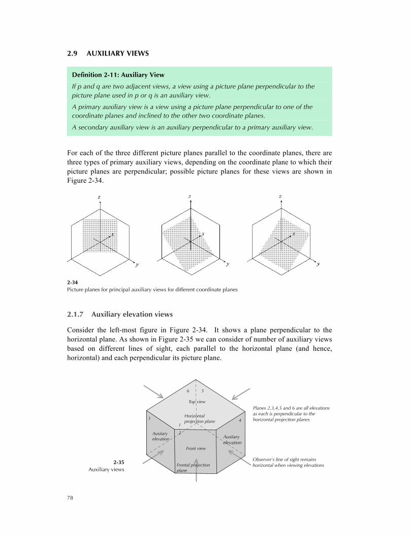
2.9 AUXILIARY VIEWS
Definition 2-11: Auxiliary View
If p and q are two adjacent views, a view using a picture plane perpendicular to the picture plane used in p or q is an auxiliary view.
A primary auxiliary view is a view using a picture plane perpendicular to one of the coordinate planes and inclined to the other two coordinate planes.
A secondary auxiliary view is an auxiliary perpendicular to a primary auxiliary view.
For each of the three different picture planes parallel to the coordinate planes, there are three types of primary auxiliary views, depending on the coordinate plane to which their picture planes are perpendicular; possible picture planes for these views are shown in Figure 2-34.
2-34 Picture planes for principal auxiliary views for different coordinate planes
2.1.7 Auxiliary elevation views
Consider the left-most figure in Figure 2-34. It shows a plane perpendicular to the horizontal plane. As shown in Figure 2-35 we can consider of number of auxiliary views based on different lines of sight, each parallel to the horizontal plane (and hence, horizontal) and each perpendicular its picture plane.
2-35 Auxiliary views
Planes 2,3,4,5 and 6 are all elevationsas each is perpendicular to thehorizontal projection planes
Observer's line of sight remainshorizontal when viewing elevations
6 5
43
1
2Auxiiaryelevation
Auxiiaryelevation
Frontal projectionplane
Front view
Horizontalprojection plane
Top view

79
2-35(continued) Unfolded auxiliary views
When solving descriptive geometry problems we eliminate the outlines of the projection planes and keep just the folding, hinge or reference lines as shown in Figure 2-36. Note that point X is located at a distance H below the horizontal picture plane as indicated by the projector from X1 to X2 in the top and front views. For the other auxiliary views 3, 4, 5 and 6, draw projectors from X1 perpendicular to the folding lines 1|k, k > 2, and transfer the distance H to points Xk.
2-36 Auxiliary elevation views
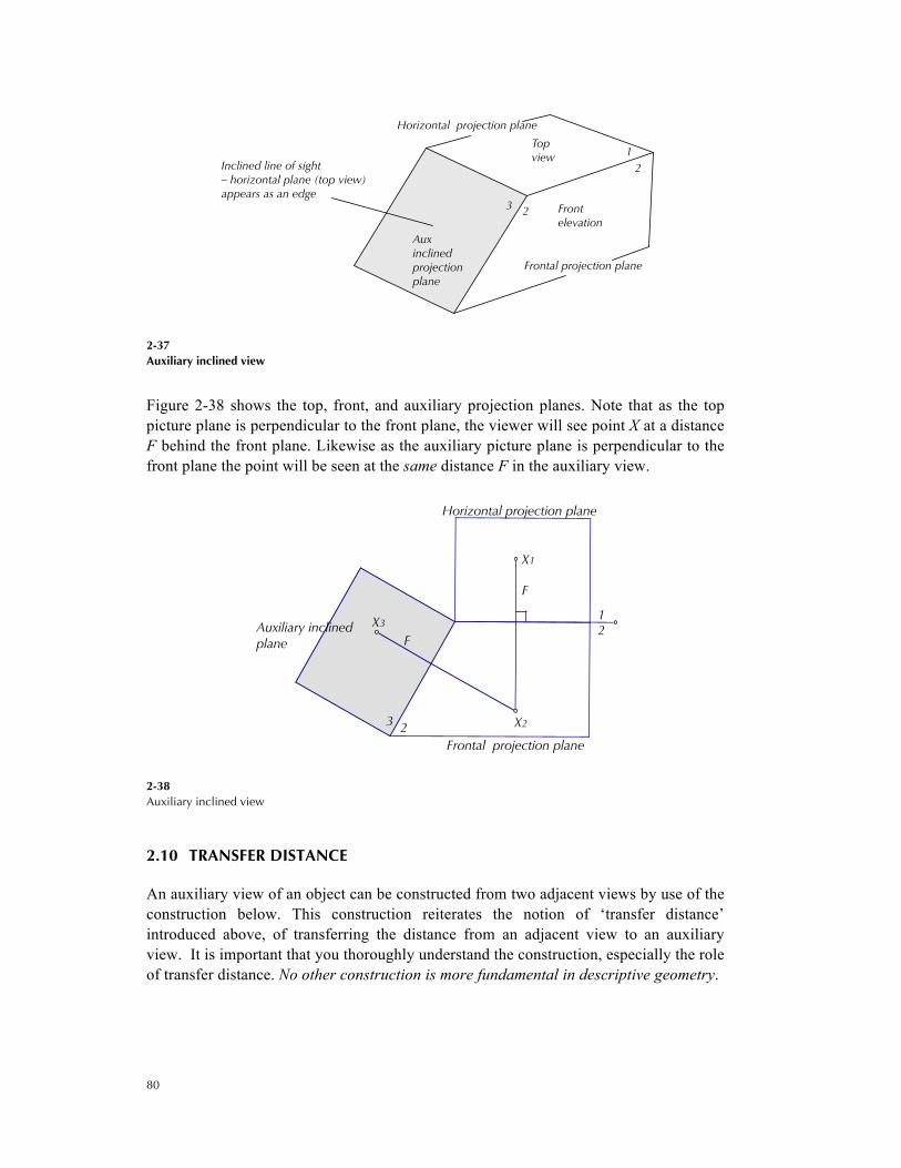
2.1.8 Auxiliary inclined views
The same idea applies when the line of sight is neither horizontal nor vertical. See Figure 2-37, where the viewer’s line of sight is inclined at some angle and the picture plane perpendicular to the line of sight is inclined with respect to the top and front views.
31
561
4
2
1
AuxElevationAux
Elevation
AuxElevation Aux
Elevation
FrontElevation
Top view
H = distance below horizontal plane
H
H
H
H
31
561
4
21
X3
X6
X4
X5
X1
X2
80
2-37 Auxiliary inclined view
Figure 2-38 shows the top, front, and auxiliary projection planes. Note that as the top picture plane is perpendicular to the front plane, the viewer will see point X at a distance F behind the front plane. Likewise as the auxiliary picture plane is perpendicular to the front plane the point will be seen at the same distance F in the auxiliary view.
2-38 Auxiliary inclined view
2.10 TRANSFER DISTANCE
An auxiliary view of an object can be constructed from two adjacent views by use of the construction below. This construction reiterates the notion of ‘transfer distance’ introduced above, of transferring the distance from an adjacent view to an auxiliary view. It is important that you thoroughly understand the construction, especially the role of transfer distance. No other construction is more fundamental in descriptive geometry.
Horizontal projection plane
Frontal projection plane
Inclined line of sight– horizontal plane (top view)appears as an edge
Auxinclinedprojectionplane
Top view
Frontelevation
3 2
21
F
F
Auxiliary inclinedplane
Frontal projection plane
Horizontal projection plane
3 2
21X3
X1
X2
81
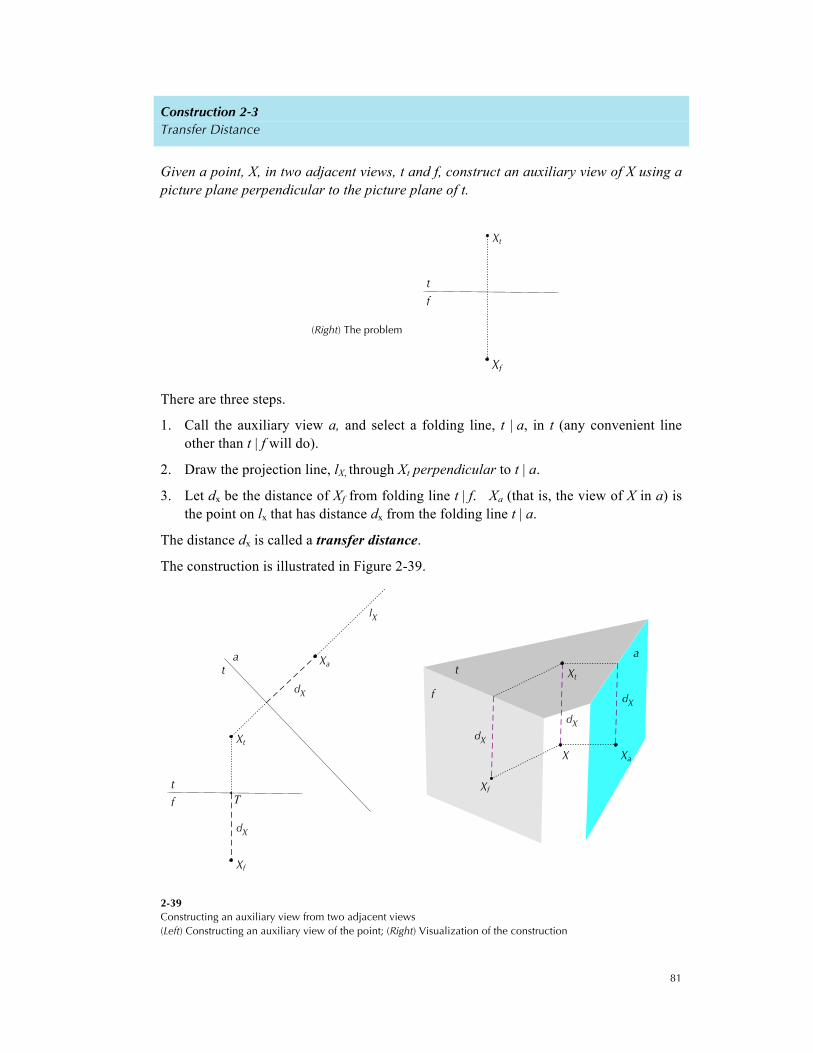
Construction 2-3 Transfer Distance
Given a point, X, in two adjacent views, t and f, construct an auxiliary view of X using a picture plane perpendicular to the picture plane of t.
(Right) The problem
There are three steps.
1. Call the auxiliary view a, and select a folding line, t | a, in t (any convenient line other than t | f will do).
2. Draw the projection line, lX, through Xt perpendicular to t | a.
3. Let dx be the distance of Xf from folding line t | f. Xa (that is, the view of X in a) is the point on lx that has distance dx from the folding line t | a.
The distance dx is called a transfer distance.
The construction is illustrated in Figure 2-39.
2-39 Constructing an auxiliary view from two adjacent views (Left) Constructing an auxiliary view of the point; (Right) Visualization of the construction
t
f
Xt
Xf
dX
dX
lX
ta
f
t
Xa
T
Xt
Xf
dX
dX
dX
a
f
t
Xf
Xt
X Xa

82
2.1.9 More on transfer distances
Figure 2-40 illustrates five consecutively adjacent projection planes in which two are always perpendicular to the third. Note that point P is located at a distance H below the horizontal view, F behind the front view and E behind the auxiliary elevation.
2-40 An example with five projection planes and its unfolding
#5 Auxiliary inclinedprojection plane
#4 Auxiliary inclinedprojection plane
#3 Auxiliary elevation plane
#2 Frontal projection plane
#1 Horizontal projection plane
Inclined line of sight #4 -auxiliary elevation planeappears as an edge
Inclined line of sight #5 -frontal plane appears asan edge
Level line of sight #3 -horizontal projectionplane #1 and auxiliaryinclined projection plane#4 appear as edges Level line of sight #2 -
horizontal projection planealways appears as an edge
Vertical line of sight #1 - frontal projection planeand all other elevation planes appear as edges
P5P2
P4
PP3
P1
1
2
5
34
P1
P2 P5
P3
P4

83
2-41 Unfolding 2-40 and the method of transfer distances
2.1.10 Examples of auxiliary view from given top and front elevation views
A typical problem situation is that the top and front views are given along with an auxiliary axis specified as shown on the right.
(Right) The problem
F = distance behind frontal plane
H = distance below horizontal plane
F
E = distance behind aux elevation #3
HE
view #4 - aux. inclinedprojection plane
view #3 - aux.elevation
view #1 - top view
view #2 - front elevation
view #5 - aux. inclinedprojection plane
52
12
13
34
P4
p3
P5
P1
P2
1f
f
t
60°
60°

84
When constructing an auxiliary especially if it is your first time at it, or a truly dense drawing it is often wise to number the points. See Figure 2-42(top left), where points 3 and 7, 4 and 6 overlap in top view and points 1 and 3 overlap in front view. We can now proceed as per Construction 2-3. See Figure 2-42(right). Hidden lines are shown dashed by Construction 2-2 (see page 73) for visibility of lines.
2-42 Constructing an auxiliary view (Top Left) The problem with points numbered (Right) Auxiliary view for the specified folding line with hidden lines shown dashed (Bottom Left) Rendered view
1f
ft
1,3
7
4
7,3
6,4 2
5,1
2
6
5
1f
ft
60°
60°
1
5
3
7
6
4
2
1,3
7
4
7,3
6,4 2
5,1
2
6
5
85
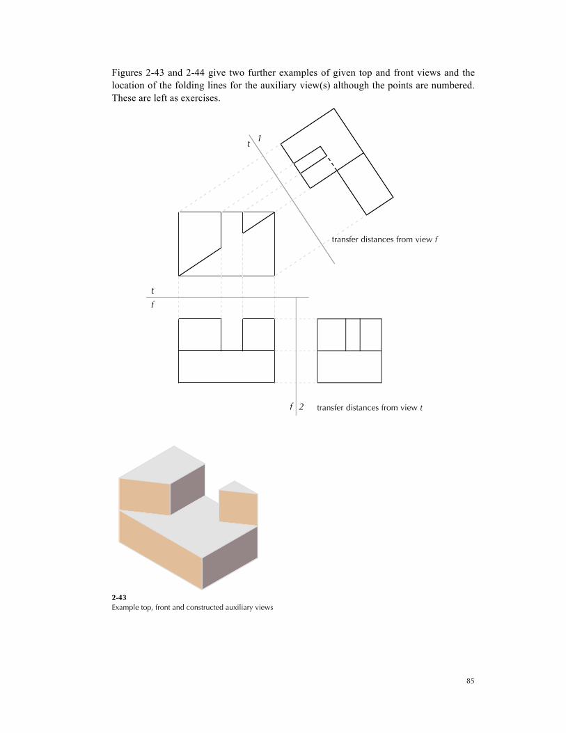
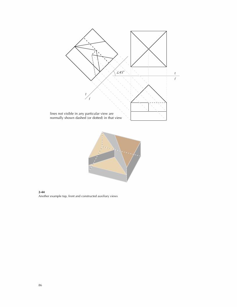
Figures 2-43 and 2-44 give two further examples of given top and front views and the location of the folding lines for the auxiliary view(s) although the points are numbered. These are left as exercises.
2-43 Example top, front and constructed auxiliary views
transfer distances from view t
transfer distances from view f
2f
1t
f
t
86
2-44 Another example top, front and constructed auxiliary views
∠45°
lines not visible in any particular view arenormally shown dashed (or dotted) in that view
1f
f
t