deposit probe measurements in danish grate and pulverized fuel...
TRANSCRIPT

General rights Copyright and moral rights for the publications made accessible in the public portal are retained by the authors and/or other copyright owners and it is a condition of accessing publications that users recognise and abide by the legal requirements associated with these rights.
Users may download and print one copy of any publication from the public portal for the purpose of private study or research.
You may not further distribute the material or use it for any profit-making activity or commercial gain
You may freely distribute the URL identifying the publication in the public portal If you believe that this document breaches copyright please contact us providing details, and we will remove access to the work immediately and investigate your claim.
Downloaded from orbit.dtu.dk on: Mar 16, 2019
Deposit Probe Measurements in Danish Grate and Pulverized Fuel Biomass PowerBoilers
Hansen, Stine Broholm; Jensen, Peter Arendt; Jappe Frandsen, Flemming; Wu, Hao; Sander, Bo;Wadernbäck, Johan; Glarborg, PeterPublished in:Proceedings. Impacts of Fuel Quality On Power Production and the Environment
Publication date:2012
Link back to DTU Orbit
Citation (APA):Hansen, S. B., Jensen, P. A., Jappe Frandsen, F., Wu, H., Sander, B., Wadernbäck, J., & Glarborg, P. (2012).Deposit Probe Measurements in Danish Grate and Pulverized Fuel Biomass Power Boilers. In Proceedings.Impacts of Fuel Quality On Power Production and the Environment

DEPOSIT PROBE MEASUREMENTS IN DANISH
GRATE AND PULVERIZED FUEL BIOMASS POWER
BOILERS.
Stine Broholm Hansen1*
, Peter Arendt Jensen1, Flemming Jappe Frandsen
1, Hao Wu
1,
Bo Sander2, Johan Wadenbäck
3, Peter Glarborg
1
1: Department of Chemical and Biochemical Engineering, Technical University of Denmark
Building 229, DK-2800, Lyngby, Denmark.
*: Corresponding Author: Stine Broholm Hansen, [email protected]
2: DONG Energy Thermal Power
Kraftværksvej 53, DK-7000 Fredericia, Denmark
3: Vattanfall A/S, Amagerværket
Kraftværksvej 37, DK-2300 Copenhagen S, Denmark
ABSTRACT Several measuring campaigns with focus on deposition behavior have been conducted
at full-scale power plants firing biomass in Denmark. These measuring campaigns
have been reviewed in this work. The focus of the review is the obtained experiences
on deposit formation, chemistry and shedding.
Corresponding samples of fuels, ash deposits and fly ash have provided information
on the transformation of inorganics in the boiler. Generally, grate fired boilers provide
a fly ash containing high contents of K, Cl and S compared to the fuel ash, while
suspension fired boilers fly ash has a composition nearly similar to the fuel ash. Inner
most biomass deposits are always salt-rich, while thicker deposit layers also contain
some Si and Ca.
Deposit probe formation rate measurements have been performed in different ways on
several boilers. Grate and suspension fired boilers seems to cause similar deposit
formation rates. Suspension fired boilers generate more fly ash, while grate boilers
form a fly ash with a higher fraction of melt formation (and thereby a higher sticking
probability) at similar temperatures. For suspension fired units it is observed that
wood with a lower ash content than straw gives rise to lower deposit formation rates.
The flue gas temperature is an important parameter in the deposit behavior of
biomass-fired boilers. Increases in the flue gas temperature of both grate and
suspension fired boilers leads to increased deposition rates and deposits with higher
contents of Si and Ca. This can be explained by increased deposition by inertial
impaction due to higher melt fractions of ash particles (containing Si and Ca) at
increased temperatures.
The shedding behavior is influenced by exposure time, probe surface temperature,
flue gas temperature and deposits chemistry. The influence of temperature on the
degree of sintering varies with the fuel type. Possibly, increased contents of Si and Ca
will lead to increases in the sintering temperature and thus to altered shedding
behavior. It is recognized that the exposure time of the deposits in the flue gas
influences the removability of the deposits.
Keywords: full-scale, grate, suspension, fly ash, deposits, shedding, chemistry,
buildup rate

1 INTRODUCTION As a consequence of Danish and international energy policy during the last 30-35
years, several full-scale measuring campaigns have been conducted in order to
investigate the thermal conversion and utilization of straw for heat and power
production - either in dedicated, grate-fired plants, in conjunction with coal in
suspension boilers and lately also in dedicated biomass (wood and/or straw) fired
suspension boilers.
Utilization of biomass for power production may increase the rate of formation of
deposits, which are difficult to remove especially in the boiler chamber and on
superheater coil surfaces compared to those formed during coal firing [1].
The difficulty arises from a high K-content of the biofuels, as potassium partly
vaporizes and form chlorides and sulfates, which may condense on heat transfer
surfaces. Potassium may also form low-melting Si-rich particles, which may stick to
the heat transfer surfaces upon impaction [1]. Deposits are formed in biomass-fired
boilers by at least four different mechanisms; Inertial impaction, thermophoresis,
condensation and heterogeneous reaction [2]. The four mechanisms apply to different
parts of the flue gas or fly ash. The large fly ash particles (>10 µm) are deposited by
inertial impaction, when the particles have sufficient inertia to traverse the gas stream
lines around a tube. Whether the particles then stick to the probe or are rebound,
depends on the stickiness of the particle and deposit surface, thus on the melt fractions
of these. Small aerosol particles (< 1 µm), often KCl or K2SO4, are deposited by
thermophoresis, where a temperature gradient is the driving force for the transport of
the particles through the gas phase toward the cold probe surface. KCl or K2SO4 are
also found as gaseous components in the flue gas. These may either condense or react
heterogeneously on the deposit surface. The gas components are thus transported
toward the surface by diffusion, with a concentration gradient being the driving force
[2].
Once formed, the deposits may be removed from heat transfer surfaces by shedding,
either naturally or induced by e.g. soot-blowing. Various mechanisms of deposit
shedding have been identified; erosion, gravity force (debonding/ melting) and
thermal or mechanical stresses. The occurrence of shedding events depend on various
physical parameters of the deposits; tensile and adhesive strengths, elastic properties,
viscosity, melting behavior, thermal expansion coefficient and thermal properties.
These physical properties leads back to the chemical composition and the temperature
of the deposit, but are often complicated to describe [3].
In order to handle ash related boiler problems, careful design of boiler chambers,
super heaters and soot-blowing equipment have been conducted. To support the
development of biomass combustion equipment, deposit probe measurements have
been performed in the last 20 years on many of the power plant boilers in Denmark.
The measuring campaigns have been conducted in collaboration between power plant
owners (now DONG Energy and Vattenfall) and Technical University of Denmark
(DTU).
The focus of the present study is a review of the full-scale measuring campaigns,
where biomass is fired without coal. The study includes a review of the applied
experimental probe techniques, and an overview of data gained on deposit build-up
rates, deposit removal, deposit chemistry and the influence of fuel type and boiler
operation conditions on the processes.

2 EXPERIMENTAL The experiments reviewed in this study have been conducted at several Danish CHP
plants, both grate and suspension fired. The data for the plants are seen in Table 1. It
should be noted that Avedøre unit 2 include two boilers; a straw fired grate boiler and
a wood/oil/gas fired suspension boiler, which both provides steam for the steam
turbine.
Table 1: Power plant data for the plants mentioned in this work
Firing
system
Fuel Thermal
input
Steam
Temp
Steam
Pressure
Commercial
operation
Ref.
MWth °C Bar
Haslev Cigar burner Straw 23 450 67 1989 [4,5]
Slagelse Grate Straw 31 450 67 1990 [4,5]
Rudkøbing Grate Straw 10.7 450 60 1990 [4,6]
Masnedø Grate Straw 33 522 92 1996 [4,7]
Ensted Grate Straw 100 470 200 1998 [8]
Avedøre Grate Straw 100 545 310 2001 [9,8]
Avedøre Suspension Wood/oil/gas 800 560 300 2001 [8]
Amager 1 Suspension Straw/wood 350 540 185 1971/2008 [10,11]
Amager 2 Suspension Straw/wood 250 480 90-110 1972/2003 [9,11]
Jordbro Suspension Wood 80 1968 [12]
In the investigated grate fired units, straw is the primary fuel. The straw is fed to the
boiler on a grate on which the combustion takes place. Primary combustion air passes
through the grate, and the temperature in the fuel-bed on the grate is typically in the
range 1000-1200 °C [13]. From the grate, the majority of the ash is dumped into the
ash pit at the end of the grate, while only a small fraction (typically less than 20 wt%)
is entrained with the flue gas [14]. One of the CHP-plants included in this study, is
‘cigar-fired’, which implies that whole straw bales are introduced to the furnace and
burn along the surface of the bale, where primary air is introduced by a jet, thereby
stabilizing the combustion on the surface [5]. Table 2 lists the ash and deposit related
measuring campaigns conducted in grate boilers and the type of examinations
performed.
Table 2: Overview of the full-scale grate experiments performed in Denmark.
Ref. Year Boiler Place Fuel
Method Examinations
Pro
be
mea
sure
men
ts
Mat
ure
dep
osi
t
sam
ple
s
Bu
ild
up
-rat
e
Ch
emis
try
of
dep
osi
ts
Co
rro
sio
n
Sh
edd
ing
[5] 1997 Haslev (cigar)
Slagelse
F, SH
F, SH
Straw
Straw
X
X
X
X
X
X
[6] 1998 Rudkøbing F Straw X X X
[7] 2000 Masnedø SH Straw X X X
[15] 2004 Ensted
Masnedø
SH
SH
Straw
Straw
X
X
X
[16] 2004 Avedøre 2 CP Straw X X X X
[17] 2006 Avedøre 2
Ensted
F/SH,CP
F
Straw
Straw
X
X
X X
[18] 2006 Avedøre 2 F/SH Straw X X X
Places: F = Furnace, SH = Near super heaters, CP = Convective Pass

For grate-fired boilers, the investigations include both analyses of deposits collected
on probes and of mature deposits collected from superheater tubes in the plant. The
data set includes quantification of the rate of deposit formation, chemical analyses of
fuels, ash and deposits, and in a few cases corrosion studies and shedding
observations.
In biomass suspension-fired units, both wood and straw pellets have been utilized as
fuels. The fuel is milled to obtain small particle sizes (< 2 mm) before entering the
furnace together with the preheated primary combustion air. The combustion then
takes place in suspension, at temperatures up to 1600 °C [13]. A small fraction of the
fuel ash particles may end up in the bottom ash, while most of the fly ash particles
formed will be transported through the furnace with the flue gas [13]. Table 3 lists the
ash related measuring campaigns conducted and the type of examinations performed
in biomass suspension fired boilers.
Table 3: Overview of the full-scale suspension fired experiments performed in Denmark
Ref Year Boiler Place Fuel Method Examinations
Pro
be
mea
sure
men
ts
Mat
ure
dep
osi
t
sam
ple
s
Bu
ild
up
-rat
e
Ch
emis
try
of
dep
osi
ts
Co
rro
sio
n
Sh
edd
ing
[12] 2004 Jordbro SH Wood X X X
[19] 2007 Amager SH, TB Straw + add X X
[20] 2008 Avedøre 2 F Wood /coal ash X X X
[9] 2011 Amager SH, TB Straw/wood X X X X
[21] 2011 Avedøre 2 F Wood/coal ash X X X (X)
[22] 2011 Avedøre 2 F, SH Wood/coal ash X X X (X)
Places: F = furnace, SH = near superheater, TB = Tube bank
In suspension fired units only probe deposits have been examined, until now. The
focus of these examinations has been on the rate of deposit formation, chemistry of
fuels, ash and deposits and shedding observations.
Two types of deposition probes have been applied in the conducted experiments. Both
simple air-cooled probes, as well as more advanced probes for in-situ deposit
measurements and soot-blowing have been applied. In the early experiments air-
cooled probes were employed. An air-cooled probe is a stainless steel probe with
thermocouples placed along the probe surface in order to control the probe
temperature to a given set-point by adjusting the air flow-rate. The deposits mass is
determined by extracting the probe after each experiment and subsequently remove
the deposits for weighing and analysis [5,7].
In later studies, an advanced in situ shedding probe has been utilized, see Figure 1.
The in situ deposit probe is constructed of a double annular tube which ensures a
uniform cooling of the probe by water and compressed air in counter-current flow.
The probe is equipped with a load cell, and online quantification of mass and heat
uptake is possible. The flue gas temperature can be measured, both by a thermocouple
and by a nearby suction pyrometer, and the deposit formation and shedding can be
observed by a video camera [9,10,16,21,22].
In a few experiments [16,23] a soot blower probe was used along with the in situ
deposition probe, in order to provide information of the removability of the formed
deposits. The soot blowing probe is a simple probe equipped with a nozzle for
ejecting high-pressure air at the end of the probe.

Figure 1: Advanced probe [9]
By adjusting the air pressure through the nozzle and the distance between the soot
blowing probe and the deposits, the force needed for removal of deposits can be
determined [16,23]. In Figure 2, three methods of applying the soot blowing probe
near the deposit probe are illustrated.
Figure 2: Application of the soot blowing probe [24]
3 RESULTS AND DISCUSSION The results obtained in the full-scale measuring campaigns will be reviewed and
compared in this section. The focus is the rate of deposit formation, the chemistry of
deposit and the observations on shedding. When examining the full-scale
experimental results, it should be kept in mind that full-scale boilers are not very well-
controlled with respect to operational parameters. Large variations in flows,
temperatures, fuel compositions etc. may occur within a relatively short time. Thus, at
best only major influences of operational parameter changes may be observed.
3.1 RATES OF DEPOSIT BUILD-UP
The rate at which the deposits are formed in a biomass-fired boiler is important, since
a decrease in the heat transfer from the flue gas to the steam cycle may be associated
with an increase in deposit mass [2].
When looking at the rate of deposit formation [g/m2/h], two definitions of the buildup-
rate of deposits have been employed, (i) the Integrated Deposit Formation rate (IDF-
rate) and (ii) the Derivative-based Deposit Formation rate (DDF-rate), as defined by
Bashir et al. [10].
The IDF-rate is determined by determining the deposit mass on the probe, at a given
time after the probe is introduced to the boiler. The deposit mass is then divided by
the probe surface area and the time of exposure, and the rate [g/m2/h] is determined.
By this method the build-up rate may be influenced by shedding events, by which
deposit is removed from the probe.

The DDF-rate can be obtained by monitoring the mass uptake signal from the
advanced probe. The DDF-rate is determined by calculating the time derivative of the
deposit mass uptake between two shedding events [g/h] as illustrated in Figure 3.
Figure 3: Original signal and determination of DDF-rate. Adapted from [10]
The rate [g/m2/h] is then obtained by dividing the time derivative by the probe surface
area. By this method only small shedding events which cannot be separated from the
measuring noise are included in the build-up rate. The DDF-rate has mainly been
employed in recent studies on suspension firing [10,21,22].
In Figure 4, the IDF rates measured are seen as function of local flue gas temperature
for grate (or cigar) fired and suspension fired units.
Figure 4: IDF rates as function of local flue gas temperature. A: Grate fired units, all straw fired. Probe
temperatures are 510 °C in Haslev and Slagelse, 650 °C in Ensted and 400-650 °C in the Avedøre grate
boiler [5,16,17]. B: Suspension fired units. Probe temperatures are within 470-590 °C in Amager
[9,10], 520 °C in Jordbro [12] and 550 °C in the Avedøre suspension boiler [20,22].
It is seen that for grate fired units there seem to be some influence of the flue gas
temperature on the deposit build-up rate. The probe temperatures vary within 400-650
°C in the experiments, with most probes set to around 500 °C. The influence of probe
temperature has been examined by Jensen et al. [16], with the conclusion that the
probe temperature has limited influence on the deposit formation rate.
For suspension fired units, it can be seen in Figure 4B that the data are rather
scattered. For these data, it should be noted that they are obtained in quite different
scenarios, both with respect to boiler configuration and fuel type.
It can be observed from Figure 4, that the IDF-rates for grate and suspension fired
units are comparable, as most IDF-rates are in the range 0-100 g/m2/h for both

technologies. This observation is surprising since during grate firing only up to 20
wt% ash is entrained while 80-90 wt% of the ash is expected to end up in the fly ash
during suspension firing [14]. For the cigar fired unit, the entrainment is considered to
be higher than in grate-fired units [5].
In order compare the deposit buildup for different fuel and combustion systems an ash
propensity has been calculated. The ash propensity is defined as:
[ ] [ ⁄ ]⁄
[ ⁄ ]⁄
The deposit flux is the IDF- or the DDF-rate, while the ash flux describes the local ash
flow near the probes. The ash flux is calculated by:
[ ⁄ ]⁄ [ ⁄ ]
[ ]
The ash content and the entrainment are given as fractions. Calculation of the ash flux
has to rely on some assumptions. The fuel flow in the boilers is assumed to be equal
to full load of the boiler, unless stated otherwise in the references. The ash content of
the fuel is in all references either provided by analysis of the actual fuel or assumed
based on earlier fuel analyses at the plant. The boiler dimensions at the probe
positions have been obtained by communications with the owners of the boilers
(DONG Energy or Vattenfall A/S). The cross-sectional area of the Haslev cigar boiler
is currently unknown for the authors. The fraction of ash entrained may vary in the
different boilers and can only be roughly estimated. It is assumed that in suspension
fired units, the entrainment is 80 % of the fuel ash, while in grate fired units the
entrainment is assumed to be 10 %, based on a mass balance provided in ref. [16]. The
calculated ash propensities based on IDF-rates are seen in Figure 5.
Figure 5: Ash deposition propensities based on IDF rates as function of local flue gas temperature. A:
Grate fired units, all straw fired [5,16,17]. B: Suspension fired units [9,10,12,19,20,22]. Probe surface
temperatures are described in Figure 4.
It is seen that the ash deposition propensities are much higher for grate fired units than
for the suspension fired units. For grate fired units up to 10 % of the ash entrained
may deposit on the probe, while for suspension fired units only up to 1 % is deposited.
Most of the data is below 0.5 % for suspension-firing. The difference in the ash
propensities of the two combustion systems may be explained by differences in the
chemical composition of the fly ash, which will be examined later.
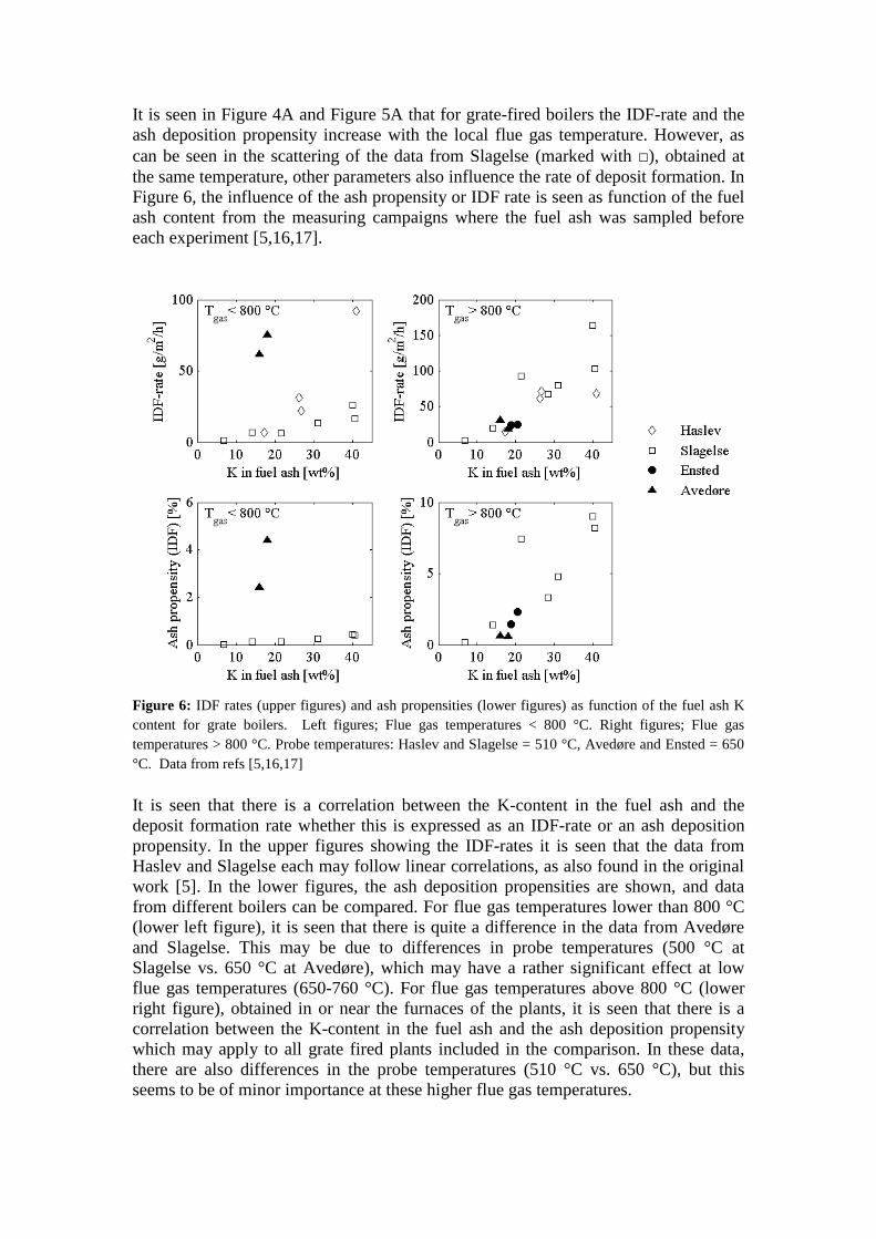
It is seen in Figure 4A and Figure 5A that for grate-fired boilers the IDF-rate and the
ash deposition propensity increase with the local flue gas temperature. However, as
can be seen in the scattering of the data from Slagelse (marked with □), obtained at
the same temperature, other parameters also influence the rate of deposit formation. In
Figure 6, the influence of the ash propensity or IDF rate is seen as function of the fuel
ash content from the measuring campaigns where the fuel ash was sampled before
each experiment [5,16,17].
Figure 6: IDF rates (upper figures) and ash propensities (lower figures) as function of the fuel ash K
content for grate boilers. Left figures; Flue gas temperatures < 800 °C. Right figures; Flue gas
temperatures > 800 °C. Probe temperatures: Haslev and Slagelse = 510 °C, Avedøre and Ensted = 650
°C. Data from refs [5,16,17]
It is seen that there is a correlation between the K-content in the fuel ash and the
deposit formation rate whether this is expressed as an IDF-rate or an ash deposition
propensity. In the upper figures showing the IDF-rates it is seen that the data from
Haslev and Slagelse each may follow linear correlations, as also found in the original
work [5]. In the lower figures, the ash deposition propensities are shown, and data
from different boilers can be compared. For flue gas temperatures lower than 800 °C
(lower left figure), it is seen that there is quite a difference in the data from Avedøre
and Slagelse. This may be due to differences in probe temperatures (500 °C at
Slagelse vs. 650 °C at Avedøre), which may have a rather significant effect at low
flue gas temperatures (650-760 °C). For flue gas temperatures above 800 °C (lower
right figure), obtained in or near the furnaces of the plants, it is seen that there is a
correlation between the K-content in the fuel ash and the ash deposition propensity
which may apply to all grate fired plants included in the comparison. In these data,
there are also differences in the probe temperatures (510 °C vs. 650 °C), but this
seems to be of minor importance at these higher flue gas temperatures.

For grate fired units it seems that an increased deposition rate can be expected when
the fuel ash K-content and the flue gas temperature are increased.
For suspension firing, a rather large scattering of data was observed whether the IDF-
rate (Figure 4B) or the ash propensity (based on IDF-rates, Figure 5B) was shown as
function of flue gas temperature. In the experiments performed on suspension firing,
chemical analysis of the fuel mixture is not conducted before each experiment, so the
IDF-rate cannot be correlated to the K-content of the fuel as was done for the grate
fired units. The influence of fuel composition is however examined by plotting the
IDF-rate as function of the straw share in wood, which is estimated from measured
ash fractions. See Figure 7. The experiments with wood with coal ash addition are
excluded from the comparison.
Figure 7: IDF rate (left figure) and ash propensity (right figure) in suspension fired units as function of
the straw share in wood. Data from Jordbro [12], Avedøre [20,22] and Amager [9,10,19].
It seems as if the fuel composition influences the rate of deposit formation. However,
any clear trend cannot be determined based on these rather scattered data.
In recent measuring campaigns, where the advanced probe was used, the DDF-rate
was calculated by only including the deposit mass change between major shedding
events. The DDF-rates are seen as function of flue gas temperature in Figure 8.
Figure 8: DDF-rate vs. flue gas temperature for suspension fired boilers. The probe surface
temperatures are within 470-590 °C. Data from refs [10,21,22]
It is seen that there are more data available for the DDF-rates, than for the IDF-rates.
This has two explanations; the DDF-rate is calculated several times during each
experiment, while only one IDF-rate is obtained, typically for the first 12 hours.

Secondly, in some experiments complete shedding of the deposits are observed. In
that case it does not make sense to calculate an IDF-rate. This behavior is observed
for wood and wood with coal ash combustion at high temperatures > 1100 °C.
It is seen in Figure 8 that for the straw/wood fuel mixture and the wood with coal ash
addition, there seem to be a correlation between the DDF-rate and the flue gas
temperature, as the rate of deposit formation increases when the flue gas temperature
increases. The temperature dependence is however not similar for the three fuel
mixtures. The data with the straw/wood fuel mixture are obtained with flue gas
temperatures in the range 750-950 °C. However, combustion of wood at much higher
temperatures, above 1200 °C, resulted in much lower deposit formation rates. It thus
seems that other parameters than the flue gas temperature has an effect on the deposit
formation rate.
The influence of fuel composition is examined by plotting the DDF-rate or ash
propensity (based on the DDF-rate) as function of the straw share in wood. The
experiments where wood with coal ash addition is used as fuel are excluded from the
comparison.
Figure 9: DDF rate (left figure) and ash propensity (right figure) as function of the straw share in wood
for suspension firing. Data with pure wood (0 % straw) from Avedøre [22], other data from Amager
[10]
It is seen that there may be higher DDF-rates and ash deposition propensities when
the straw share exceeds 50 % as compared to fuels with lower contents. It however
seem as if the deposition rates are more influenced by differences in the flue gas
temperatures and the influence of fuel composition on the deposit formation may be
limited compared to the influence of temperature.
The difference in the temperature dependence for the various fuels observed in Figure
8, may thus also be caused by other differences in the boilers, as these are quite
different in construction.
When examining the IDF- and DDF-rates obtained for suspension firing, the
temperature seems to influence the DDF-rate, while the fuel composition mainly seem
to influence the IDF-rate, though no clear correlation could be detected.
That the fuel composition seems to have a larger influence on the IDF-rate than on the
DDF-rate may be explained by the fact that major shedding events may be included in
the determination of the IDF-rate and will thus have a large impact on the IDF-rate
and not on the DDF-rate. The chemistry of ash and deposits may have more influence
on the strength of the deposit and thus on the shedding than on the deposit formation.
Contrary, the flue gas temperature may influence the build-up rate more than the
shedding rate, possibly through influences on the physical state of the ash particles.

3.2 CHEMISTRY OF ASH AND DEPOSITS
It was seen in the previous section, that the deposit formation rates (IDF) was on
similar levels for grate and suspension-fired units (Figure 4). This was explored
further by examining the ash propensity of the two systems (Figure 5) and it was
found that for grate-fired units up to 10 % of the incoming ash may deposit on the
probe, while for suspension-fired units only up to 1 % is deposited (based on IDF-
rates). The ash in grate-fired units is thus more prone to end up as deposits than the
ash in suspension-fired units. As the flue gas temperatures in the systems were similar
at the probe positions, the difference may be caused by chemical differences of the fly
ashes. Such differences will also lead to differences in the chemistry of the deposits
formed. In this section the chemistry of the fly ash and deposits will be reviewed
along with influences of operational parameters.
3.2.1 FLY ASH CHEMISTRY The firing technology will have great impact on the fly ash formation due to
differences in entrainment etc. In Figure 10, fuel and fly ash compositions are
compared for each of the two firing technologies, grate and suspension firing, to gain
an idea on how the ash transformations occur in or near the combustion zones. The
chemical examinations in this work mainly focus on the five major ash forming
elements in biomass combustion; Si, Ca, K, Cl and S.
Figure 10: Fly ash composition vs. fuel ash composition. Points on or near the diagonal line indicate
that the fuel and fly ash compositions are similar. A: Grate; fuels are straw from refs [5,17]. B:
Suspension. Fuels are various straw/wood mixtures from refs [9,10,12]
It is seen that for grate-firing, the fly ash composition is quite different from the fuel
ash composition, as almost no points are placed near the diagonal line. The fly ash is
rich in K, Cl and S and depleted of Si and Ca compared to the fuel ash. This is
contrary to suspension-firing, where the fly ash to a large extent resembles the fuel
ash, as seen by the distribution of points close to the diagonal line. Only a slight
enrichment of K, Cl and S is found in this combustion system. The difference in the
fly ash formation behavior can be explained by the difference in entrainment of ash in
the two combustion systems. As K, Cl and S are volatile elements in the fuel, these
are to some extent released to the gas phase in the combustion zone, while Ca and Si
are retained in the solid fuel (or ash) particles [1]. In grate-firing most of the solid ash
particles remain in the bottom of the furnace and Ca and Si are thus only found in the
fly ash to a limited extent. Contrary, in suspension-firing the ash particles are
entrained to a large extent, which leads to the similar composition of the fuel ash and
fly ash.

The differences of the chemical composition results in different melting behaviors and
thereby stickiness of the fly ash particles as well as of the formed deposits. Zhou [25]
has presented empirical correlations for predicting the melt fraction of ashes as
function of temperature based on the chemical analysis of the ash. The basis of the
correlation is a number of ash melting tests performed on straw ashes [26], and it can
thus not be expected to apply to wood ashes. The correlations have been used to
calculate melting curves of fly ashes of straw from grate and suspension firing. The
result is seen in Figure 11.
Figure 11: Predicted melting curves of fly ashes from grate and suspension firing of straw. Ash
compositions from ref [9].
It is seen that there is significant difference in the predicted melt fraction of straw fly
ashes in the temperature range 650-1300 °C, which can partly explain the difference
in the deposition behavior observed for grate- and suspension-fired units.
The differences in ash deposition propensity may furthermore be caused by the
physical form of the fly ashes, which may be quite different in the two combustion
systems. In grate fired units, K and Cl dominates the fly ash composition and is
expected to be found as KCl vapors or aerosols, which will easily stick to heat transfer
surfaces. In suspension fired units K and Si dominates and are mainly found as solid
K-silicates [1].
3.2.2 DEPOSITS CHEMISTRY The deposits are formed from the fly ash and the deposit chemistry is thus influenced
by both the formation of fly ash and the ability of the fly ash to deposit on heat
transfer surfaces. In the following it will be reviewed how the chemical
transformations occur in the two combustion systems based on the chemical analysis
of fuels, fly ash and deposits collected in the measuring campaigns.
In Figure 12, the chemical composition (with respect to the five major ash forming
elements) of deposits formed on probes near super heater tubes can be seen for three
firing cases; straw in grate-firing, straw in suspension-firing and wood in suspension-
firing. In Figure 12A the ash compositions of the fuels used in the three cases are
seen. It is seen that the two straws are similar, though the straw fired in the grate
boiler has a higher K content than the straw fired in suspension. The compositions of
the deposits formed in the two cases of straw combustion are seen in Figure 12B. It is
seen that the deposits from suspension firing contains more Ca and Si and less K than
the deposits from grate firing. This is as could be expected based on the fly ash
chemistry examined previously. Two cases of suspension firing are seen in Figure 12;
with straw and with wood as fuel, respectively. In Figure 12A it is seen that there are

Figure 12: Corresponding fuel and deposit compositions in three firing cases. The fuel ash
compositions are seen in the left figure, while compositions of the corresponding deposits are seen in
the right figure. Data for straw in grate-firing [5], pure straw in suspension firing [9] and for pure wood
in suspension firing [12]
differences in the fuel ash compositions of the two fuels. Wood contains more Ca and
less Si and Cl than straw. These differences are also found in the compositions of the
deposits as seen in Figure 12B.
In Figure 12, the deposits chemistry has been provided as a bulk chemical
composition. In reality, the deposits are composed of layers, with different structures
and possibly also chemical composition. Furthermore, there are differences in the
deposits on the upstream and downstream side of the probe. The upstream side means
the half circle of the probe facing the flue gas direction.
For grate fired units, both probe deposits and mature deposit samples from
superheater tubes have been examined with respect to chemistry and morphology.
In Figure 13 a SEM photograph of a mature upstream deposit cross-section from the
Ensted straw fired grate boiler is seen. The mature deposit is collected from a super
heater tube at a position in the boiler where the flue gas temperature is < 900 °C. The
super heater steam temperatures are within 389-470 °C at the sample position [15].
Figure 13: SEM photograph of the layered structure of a mature super heater deposit collected at the
Ensted straw fired grate boiler. From ref. [15]
The layered structure is clearly seen in Figure 13. The innermost layer is found on top
of an iron oxide scale of the super heater tube. The layer is composed of sub layers of
K2SO4 and KCl flakes. The intermediate layer of the mature deposit contain many Si-
and Ca-rich particles, which are glued completely together by KCl, and the layer is

thus quite dense. The outer layer also contains Si- and Ca-rich particles glued together
by KCl and also by K2SO4. The outer layer is however very porous [15].
Mature deposit samples have also been collected from the super heater tubes of the
Masnedø straw fired grate boiler. In this boiler the steam and flue gas temperatures at
the sample position is higher than in the Ensted boiler (387-521 °C and 960-1019 °C,
respectively). In this boiler the innermost layer is also composed of KCl and K2SO4,
but the distribution of these two compounds in the sub-layers varied, without any
systematic variation with steam temperatures at the sample location. The intermediate
layer contained almost no chlorine which is explained by the higher temperatures of
the Masnedø boiler. The outer layers of the deposits collected in Masnedø was quite
similar to the outer layers collected in Ensted, both with respect to morphology and
chemistry [15].
The K/(2S+Cl) molar ratio of the layers from the two boilers have been calculated
from the chemical analysis to determine whether the K is present in other forms than
KCl and K2SO4. It is found that the ratio is ≈1 for the innermost layer and K is thus
only expected to be found as KCl and K2SO4. In the intermediate and outer layer the
ratio is above 1 and K can be expected to be found in other forms [15].
The chemical composition of the mature deposit samples are found to be quite similar
to the chemical composition of the deposits collected on probes in straw fired grate
boilers [15]. The morphology is however quite different, especially for the inner
layers. The deposits on probes have a thinner and less dense inner KCl layer
compared to the mature deposits. The inner layer of probe deposits from straw fired
grate boilers is typically followed by a porous KCl-rich layer and then by an outer
layer of Si- and Ca-rich particles glued together by KCl [15].
In Figure 14 the chemical compositions of two probe deposits obtained in the Avedøre
straw fired grate boiler in 3 and 30 days, respectively, are seen [16].
Figure 14: Chemical composition of deposit layers collected at the Avedøre straw fired grate boiler
with a 500 °C probe where the flue gas is within 700-800 °C. From ref. [16].
It is seen that the deposit accumulated in 3 days is only composed of two layers.
These are described as a thin (0.5-1 mm) inner white and powdery layer and a 5 mm
outer grey layer, which is quite hard. It is seen in Figure 14A that the inner layer is
composed of mainly K and Cl, while the outer layer also contains some Si and Ca.
When the exposure time of the probe is increased to 30 days in the same conditions,
differences in the deposit structure can be observed as seen in Figure 14B. The deposit
then contains three layers. These are described as an inner layer similar to the short-
time probe deposit, although slightly grey. The intermediate layer is a 1-3 mm grey
and hard layer, while the outer layer is a 1-2 mm grey, porous and powdery layer. The
30 days deposit thus has a greater resemblance with the mature deposits.
Looking at the chemical compositions of the deposits from the two exposure times in
Figure 14, it is seen that there are only limited differences, mainly in the composition

of the inner layer, which contains more Si, Ca and S at the long exposure time. It thus
seem like time has an influence on the morphology of the deposits more than on the
chemical composition. The deposits on the downstream side of the probe are found be
composed of K and Cl and to be unaltered with the longer exposure time, both with
respect to chemistry and morphology [16].
For suspension firing, no analysis of mature deposits is available at this point. Bashir
et al. [10] has made a detailed analysis of the deposit layers formed on a probe during
suspension firing of a straw/wood mixture containing at least 46 wt% straw. The
chemical analysis with respect to the 5 elements of interest is seen in Figure 15.
Figure 15: Chemical composition of deposit layers collected at the Amager straw/wood fired
suspension boiler with a 500 °C probe where the average flue gas temperature is 876 °C [10].
It is seen in Figure 15 that the deposit from suspension firing has much higher
contents of Si and Ca in all parts of the deposit than what has been observed for straw
grate-firing. This difference may occur due to the presence of wood in the fuel
mixture and/or due to shift of firing technology. It is seen that only the inner upstream
layer and the downstream layers have significant amounts of K, Cl and S. The
K/(2S+Cl) molar ratio is in all layers > 1, indication that K is present in other forms
than as KCl and K2SO4. SEM-EDS analysis conducted on the upstream outer layer of
deposits formed during combustion of pure straw [9] indicate that molten particles
rich in K, Ca and Si are found within the deposit along with smaller particles rich in
K, S and Ca.
Analysis of the deposit layers has also been conducted for deposits obtained on a
probe during suspension firing of wood at two temperatures in the Avedøre
suspension boiler. The result is seen in Figure 16.
Figure 16: Chemical composition of deposit layers collected at two positions in the Avedøre wood
fired suspension boiler with a 550 °C probe temperature. From ref. [22].
The chemical analysis seen in Figure 16 is supported by SEM-EDS analysis of the
deposits [22]. For the deposits obtained in the super heater section where the flue gas
temperature is around 800 °C (Figure 16A), the morphology and the chemical

composition of the deposits on the upstream and the downstream side of the probe is
quite similar. Only one deposit layer is obtained due to limited deposition occurring at
these conditions. The deposits are composed of mainly K and Ca, but also Cl and S
appears. The deposits are found to be clusters of very small particles. For the
downstream deposit all the K is found to be water soluble, while the water soluble
part is 88 % of the upstream deposit. It is found that only part of the soluble K (40-60
%) is found as sulfates and chlorides. The rest is expected to be found as other water
soluble compounds such as KOH or K2CO3 [22].
These deposits obtained with wood and flue gas temperatures at 800 °C are thus quite
different from the deposits obtained with a straw/wood mixture at an average flue gas
temperature of 876 °C seen in Figure 15. In the super heater deposits obtained with
the straw/wood mixture, ash particles composted of K, Ca and Si was found in the
deposits. These were not found in the deposits obtained with wood, except for very
few ash particles in the downstream deposits.
In the Avedøre suspension fired boiler a deposit probe was also placed in the furnace,
below the screen, where the flue gas is 1300 °C. The compositions of the deposits
collected on the probe are seen in Figure 16B. It is seen that the layers of the upstream
deposits are quite different. The outer deposit is dominated by Si, Ca and K, while the
inner deposit also contains S. Common for the two layers is the presence of spherical
ash particles composed of Si, Ca and K, and partially melted particles rich in K and
Si. The K in the outer layer is insoluble and thus found as K-silicates, K-Al-silicates
or K-Ca-silicates. In the inner layer 40 % of the K is water soluble and found as
mainly K2SO4 [22]
The downstream deposits obtained at 1300 °C contain a lot of S-species, likely
K2SO4, which is partially melted or found as small particles. Besides this, also
spherical particles of K, Si and Ca are found along with molten particles of K and Si.
Most of the K is water soluble and some is expected to be found as KOH or K2CO3
[22].
It is seen in this section that time influences the structure of the deposits, with respect
to number of layers and to the thickness and morphology of the individual layers. The
layers become thicker and denser with increased exposure time. The exposure time on
the other hand do not seem to influence the chemistry of the deposits. These
influences of time are seen by comparison of mature deposits with probe deposits and
comparison of two probe deposits obtained with short and long exposure times,
respectively. The firing technology is seen to influence the chemical composition of
the deposit. Deposits obtained in suspension fired units contain more Si and Ca than
deposits obtained in grate fired units with a similar fuel. The differences apply to all
layers of the deposits and can be explained by differences in the fly ash formation.
The choice of fuel naturally also influences the chemistry of deposits. Deposits from
suspension firing of straw contain Si, Ca, K and Cl, whereas deposits from wood
firing are dominated by Ca and K. This is explained by the differences in fuel ash
chemistry. It is found that deposits from wood suspension firing almost don’t contain
fly ash particles, contrary to deposits from straw suspension firing obtained at similar
temperatures. It is possible that this may be explained by differences in the melting
behavior of the ashes or by lower ash contents of wood, leading to lower ash fluxes. It
is estimated that in the examined experiments the average ash flux in the straw/wood
fired suspension boilers is 18000 g/m2/h at the probe position. The average ash flux
for the wood fired experiments is only 8100 g/m2/h. Flue gas temperature is also
observed to influence the deposit morphology and chemical composition. The
influence of temperatures will be examined further in the following section.

3.2.3 INFLUENCE OF TEMPERATURE ON DEPOSITS CHEMISTRY It was seen in the previous section that the deposits are influenced by the local flue
gas temperatures as differences in the deposit composition was quite different in two
places of a wood fired suspension boiler. For grate fired boilers, the chemistry of
deposits at different boiler positions has also been examined.
In the measuring campaign conducted in Haslev and Slagelse [5], the fuel and fly ash
were sampled in each test along with deposits collected in two positions in the boiler.
In Figure 17, the fly ash composition (also seen Figure 10A) is compared to the bulk
compositions of the deposits formed in the furnace chamber at flue gas temperatures
of 835 °C or 873 °C, and to the deposits collected near the super heaters at flue gas
temperatures near 650 °C.
Figure 17: Deposit probe compositions vs. fly ash compositions in grate fired boilers.
A: In the furnaces (835/873 °C). B: Near the super heaters (650°C). Data from Haslev and Slagelse [5]
It is seen that in the furnaces (at high temperatures), the deposits contain more Ca and
Si and less K and Cl compared to the fly ash. At the probes near the super heaters,
where the flue gas temperature is 650 °C, the deposits chemical composition
resembles that of the fly ash. There is thus a shift in the deposition behavior with flue
gas temperature.
This has been explored further by calculation of an enrichment factor for each
element;
In the calculation of the enrichment factor, the fuel ash composition is used rather
than the fly ash composition, since the fuel ash composition has been examined in
more measuring campaigns and is often known to a larger extent than the fly ash
composition. It should be kept in mind when examining these data, that the
enrichment factor is based on two ash splits; one split occurring in the combustion
zone (especially for grate-firing) and one split occurring during deposit buildup,
where the elements behave differently.
The enrichment factors for the five main ash forming elements in grate-firing of
biomass are seen as function of flue gas temperature in Figure 18. It is seen that for Si
and Ca, the enrichment ratio is low at the low temperatures and approaches an
enrichment factor around 1 at higher temperatures, except for the downstream
deposits. For Cl, the enrichment factor is high at low temperatures and then decrease
with increasing flue gas temperatures. It seems that deposits formed at high flue gas
temperatures can be expected to be depleted of chlorine. A similar behavior is
observed for sulfur, though with a much larger scattering of data. The enrichment

Figure 18: Enrichment factors for the five main ash forming elements as function of flue gas
temperature for deposits collected in grate fired boilers; Haslev, Slagelse, Avedøre and Ensted
[5,16,17]. The point shape indicate at which position on the probe, the deposits are collected; upstream
means the half circle of the probe facing the flue gas direction.
factors for K are between 1 and 2 at the low flue gas temperatures. At higher
temperatures the K enrichment factor decrease and approach 1.
The enrichments factors have also been calculated for the deposits collected on probes
in suspension fired boilers. The results are seen in Figure 19. It is seen that the
influence of the flue gas temperature on the enrichment factors is the same as
observed for deposits from the grate fired units in Figure 18. The main differences
observed among the enrichment factors from the two combustion technologies are that
the enrichment factors of K, Cl and S are higher in suspension-fired units at the low
temperatures. Furthermore, the downstream deposits can be expected to contain some
Si and Ca, contrary to deposits from grate fired units. These differences can all be
related to the higher entrainment of ash in suspension firing.
The influence of temperature on the deposits chemistry can be explained by the
deposit mechanisms involved in deposit buildup.

Figure 19: Enrichment factors for the five main ash forming elements as function of flue gas
temperature for deposits collected in suspension fired boilers [12,20,22]. The point shape indicate at
which position on the probe, the deposits are collected; upstream means the half circle of the probe
facing the flue gas direction.
The decrease in K, Cl and S enrichment factors with increasing flue gas temperature
can be explained by limited condensation at high temperatures. The flue gas contains
KCl and K2SO4, which may condense on the cold probe. The rate of condensation is
determined by the difference in the flue gas concentration and the saturation
concentration of KCl or K2SO4 near the surface. The surface temperature of the
deposit on the probe is determined by the flue gas temperature after some initial build-
up has occurred. At high temperatures the saturation concentration is high and the
gaseous species will not be transported toward the surface. This may explain the
lower enrichment ratios of K, Cl and S observed at higher temperatures. The
saturation concentration of KCl increases drastically around 700 °C, while the
saturation concentration of K2SO4 is low up to temperatures around 1100 °C [27].
This explains the differences observed between Cl and S, as these two elements are
mainly transported to the deposits as KCl and K2SO4.

The increase in the enrichment factors of Ca and Si with increased flue gas
temperatures can be explained by a higher melt fraction of the fly ash particles
containing Si and Ca and of the deposit surface at high temperatures. When the melt
fractions increases, the particles are more prone for sticking on the probe surface
when the particles coincide with the surface by inertial impaction.
It has thus been found in this section that the flue gas temperature influences both the
rate of deposit formation and the deposits chemistry. Large particles deposit by
inertial impaction and the increase in deposit mass and change in bulk chemical
composition is thus most pronounced for this mechanism. When the rate of inertial
impaction increases with temperature, the rate of deposit formation is thus increased
and the bulk chemical composition is changed toward higher contents of Si and Ca.
The influence of varied probe temperature has been examined in the measuring
campaign at the Avedøre straw fired grate boiler [16]. The flue gas temperature was
within 700-800 °C, while the probe surface temperature was varied within 400-550
°C. It is found that neither the deposition rate nor the deposit chemical composition is
varied with these variations in probe temperature, except for the chlorine content of
the deposit, which seem to be lowered at higher probe temperature. A similar
conclusion is obtained by Michelsen et al. [6] at the Rudkøbing straw fired grate
boiler. Probes with temperatures of 460 °C and 550 ° were found to collect deposits
with similar chemical compositions. Deposits from an uncooled probe were however
depleted of chlorine [6].
It is however found in both experiments that the thickness of the deposit is increased
with increased probe temperature and that the morphology is altered. At high probe
temperatures the deposits seem to have been molten to a larger extent [6,16]. The
overall deposit patterns also changes with temperature; at 400 °C the deposit is
uniform along the probe. At 500 and 550 °C a ‘camel-back’ like deposit was formed
[16].
3.3 SHEDDING OF DEPOSITS
The deposits formed on the surfaces in a biomass fired boiler may be removed by
shedding events. Various types of removal mechanisms have been observed and these
mechanisms have been reviewed by Zbogar et al. [3]. In Table 4, an overview of
shedding mechanisms can be seen, where the place of shedding and the deposit type,
with respect to the physical state is indicated for each mechanism.
Table 4: Deposit removal mechanisms along with indication of type of deposit and place at which the
shedding occurs [3]. Place of shedding Deposit type
Tube-
deposit
interface
Within
deposit
Surface
removal Powdery
Lightly
sintered
Heavily
sintered
Running
slag
Erosion X X (X)
Gravimetric X X X (X)
Melting X X
Thermally induced tensions
- By combustion fluctuations
- By load changes
- By soot blowing
X X (X) X
Mechanically induced tensions
- By ‘natural’ mechanical
fluctuations
- By soot blowing
X X X X (X)

Erosion, gravimetric shedding, melting and to some extent also thermal tensions can
be termed natural shedding mechanisms, while artificial shedding is often the result of
induced thermal and mechanical stresses. As seen in Table 4, soot blowing may be a
method for inducing mechanical or thermal tensions on formed deposits. Soot blowers
operate by injecting jets of steam, water or high-pressure air into the boiler at
positions where deposits are formed. The injection occurs through a nozzle located at
the end of a long, rotating lance. The efficiency of the soot blower depends on the
force of the jet, often given by the peak impact pressure (PIP) at a given distance from
the nozzle and on the state of the deposit [16]. The thermally and mechanically
induced tensions may lead to brittle fracture within the deposit or debonding from the
tube surface, depending on the tensile strength of the deposit and the adhesion
strength of the tube-deposit interface. The occurrence of shedding events is thus
correlated to the strength development of the deposits. The strength can mainly be
gained by either solidification of molten or partially molten material or by sintering of
solid particles [3]. These processes depend on the temperature and the physical and
chemical structure of the deposits.
The strength development and shedding of deposits has been examined to some extent
for deposits formed during coal combustion and systematically for deposits in kraft
recovery boilers, where the deposits are composed of alkali salts. Unfortunately only
limited studies have been conducted in biomass fired boilers, and the experiences
from coal and kraft recovery boilers can only be adapted to this fuel to a limited
extent [3]. In the following the observations made in the Danish full-scale boilers
firing biomass will be reviewed.
Shedding of deposits has been examined in grate fired units in two measuring
campaigns, both conducted at the Avedøre straw fired grate boiler [16,18]. In one
measuring campaign, a probe was placed in the top of the furnace chamber at the inlet
to the superheater and the influence of flue gas temperatures in the range 800-1100 °C
were observed with a probe temperature kept at 500 °C [18]. It was observed that the
shedding of deposit took place by surface melting and droplet formation. It was found
that the flue gas temperature governs the state of the deposit; at 900 °C and below, the
deposits were solid. When the temperature increases to around 1000 °C, the deposits
contain both melt and solid particles. At 1100 °C or above, the deposit surface layer is
completely melted, and the deposits are rapidly removed as droplets [18].
In the other probe measuring campaign conducted in the Avedøre grate-fired plant the
probe was placed in convective section, where the flue gas temperature was within
700-800 °C.
During this measuring campaign at the Avedøre grate-fired boiler, the deposition
behavior on the superheater tubes (SH1) near the probe has also been observed by
camera. The temperature of the steam inside the tubes was around 400 °C and the tube
metal temperature at this point can thus be assumed to be within 400-450 °C. The
plant soot blower located near the tubes was approximately 1 m away, and the PIP of
the jet at the tube is estimated to be 60 kPa [16].
In the first day after tube cleaning and boiler start-up a thin white layer accumulates
on the SH tubes. In the second day a thick, snow-like deposit is formed. At seven days
after startup the deposits on the upstream side of the probe is elliptical and dark grey.
At the downstream side, the deposits are thin and slightly grey.
From this point forward no effect of the plant sootblowing can be detected and in the
following weeks the deposits grow and bridging deposits between tubes were formed.
The deposit behavior on the SH tubes is found to be in qualitative agreement with the
behavior of the probe deposit [16].

During the experiments with the probe, the probe surface temperature was varied in
the range 400-550 °C [16]. A soot-blower probe was used along with the deposit
probe, and thereby the needed peak impact pressure (PIP) for removal of the deposits
could be determined. A critical PIP was defined as the needed PIP for removal of
more than 75 % of the deposit on the probe. In Figure 20 the needed PIP measured
after 100 hour exposure times (4 days) and just before the probe is removed at the end
of the experiment (260-740 hours exposure time) are seen.
Figure 20: Critical PIP for removal of front deposit for different probe surface temperatures and
exposure times. At 550 °C less than 25 % deposits are removed at max PIP. From ref [16]
As seen in Figure 20, the probe temperature and the exposure time influence the
removability of the front deposit. Higher probe temperatures and long exposure times
lead to deposits which are difficult to remove.
This is considered to be due to sintering and thereby increased deposit strength and
increased deposit-tube adhesion strength. The mechanism of removal is in all cases
brittle fracture and debonding induced by the sootblower.
For the deposits at the downstream side of the probe it was found that these were
easily removed, except those at the high temperature, 550 °C [16].
The upstream and downstream deposits are found to have differences in the chemical
composition as the downstream side is mainly composed of K, Cl and S while the
upstream side also contains some Si and Ca. As the deposits on the two sides of the
probe can be expected to have similar temperatures within one experiment, it is
considered that the chemistry of deposits also influences the strength and removability
of deposits, since the shedding behavior is different at the two sides of the probe.
For suspension fired boilers, shedding has been examined for straw/wood mixtures
[23,24], for wood [22] and for wood with coal ash addition [21; 22].
In the measuring campaign with straw/wood mixture as fuel [23,24], the probe was
placed just above the screen tubes, where the flue gas temperatures are within 600-
1050 °C. The influence of several parameters on shedding was examined with the
advanced in situ deposition probe. Also in some cases a soot blower probe was used
to determine the needed PIP to remove the deposit.
In the straw/wood fired boiler, shedding was observed to take place by debonding as
natural shedding (when no soot blowing was applied) and as soot blower induced
shedding. Furthermore, shedding by erosion caused by impaction of non-sticky
particles was observed by visual inspection of the probe during operation. Shedding
by probe deposit surface melting was not observed, even though the flue gas
temperature was above 1000 °C during periods of the tests [24,23].
The mass uptake signal from the advanced probe used in the suspension fired boiler
has been examined along with temperature measurements and boiler operational data
to identify the parameters influencing the shedding. The shedding has been observed
by three measures; the shedding rate [g/m2/h], the mass shedded in an event [g/m
2]
and the shedding frequency [h-1
].
It is found that when the flue gas temperature or the deposit mass on the probe are
increased (>850 °C and >5000 g/m2, respectively) the shedding size is not
significantly changed. The mean sizes of shedding events are 716 g/m2 and 805 g/m
2
for natural and soot blower induced shedding events, respectively. The mean shedding
frequency is however increased from 1.0 to 1.9 times per hour for natural shedding as
the deposit mass load on the probe is increased from below to above 5000 g/m2 (flue
gas temperature > 850 °C). The increase in the shedding frequency leads to an overall
increased shedding rate with increased flue gas temperature and deposit mass load.
Although the shedding rate increases, the percentage of deposit removed in a shedding
event decrease, since the amount shedded is relatively stable. It is generally observed
that the shedding rate is lower than the DDF-rate, which implies that more and more
deposits are attached to the probe and less and less can be removed as buildup time
goes by [23]. It is considered that at high temperatures partial melting of the deposits
occur, the deposit sinter and thereby the adhesion strength is enhanced. It is
furthermore seen that at high temperatures the deposit layers are thicker and the
upstream and downstream layers are connected, making the debonding more difficult.
The influence of straw share in wood and of the probe surface temperature has also
been examined. It is found that straw share (above or below 20%) does not have a
significant impact on the shedding rate. The shedding rate is however in most cases
higher at 500 °C than at 600 °C probe temperature, both for natural and soot-blower
induced shedding. The influence of probe surface temperature and exposure time on
deposit shedding has been examined by applying the soot blower probe. The
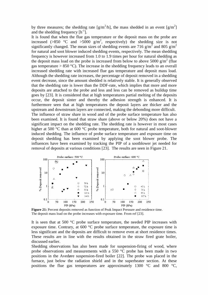
influences have been examined by tracking the PIP of a sootblower jet needed for
removal of deposits at various conditions [23]. The results are seen in Figure 21.
Figure 21: Percent deposits removed as function of Peak Impact Pressure and residence time.
The deposit mass load on the probe increases with exposure time. From ref [23].
It is seen that at 500 °C probe surface temperature, the needed PIP increases with
exposure time. Contrary, at 600 °C probe surface temperature, the exposure time is
less significant and the deposits are difficult to remove even at short residence times.
These results are in line with the results obtained in the straw fired grate boiler,
discussed earlier.
Shedding observations has also been made for suspension-firing of wood, where
probe observations and measurements with a 550 °C probe has been made in two
positions in the Avedøre suspension-fired boiler [22]. The probe was placed in the
furnace, just below the radiation shield and in the superheater section. At these
positions the flue gas temperatures are approximately 1300 °C and 800 °C,

respectively. In the superheater section, where the flue gas temperature is ≈800°C the
deposit mass uptake is slow. After some time, the deposit mass on the probe becomes
constant, indicating equilibrium between deposition and shedding rates. The type of
shedding at this position is not identified, but due to insignificant mass loss, it is
probably not by debonding [22]. A possible mechanism could be erosion, but this has
not been verified. At the location with flue gas temperatures around 1300 °C, the
deposit buildup was fast and many shedding events with almost complete removal of
the deposit by debonding took place [22].
It can thus be concluded that the shedding behavior is quite different from what is
observed with the straw/wood mixture as fuel and that a thick layer of deposit were
never established on the probe.
The effect of adding coal ash to the wood in a suspension fired boilers has also been
tested, with applied coal ash to wood ash ratios within 3.6 to 7.4 [21,22]. It was found
that the overall deposition and shedding patterns are similar at the two positions with
flue gas temperatures 800 and 1300 °C with the addition of coal ash. It is however
observed that at the 800 °C position, the constant amount of deposit obtained is lower
than observed for the pure wood firing. The deposits obtained with coal ash addition
were furthermore found to be easier to remove from the probe after the experiment. At
the position with flue gas temperatures around 1300 °C, it was found that the build-
up/complete shedding cycle is shorter than observed for wood firing. Without coal ash
addition the cycle is approximately 10 hours, whereas adding coal ash leads to a cycle
of approximately 2 hours [22]. The coal ash addition thus has a positive effect.
Shedding behavior has thus been studied in four cases of biomass combustion; (i)
straw fired grate boiler at high flue gas temperatures, (ii) straw fired grate boiler at
low flue gas temperatures and varied probe temperatures (iii) suspension firing of
straw/wood at a range of flue gas and probe temperatures and (iv) suspension firing of
wood at high and low flue gas temperatures.
It is observed that in straw fired grate boilers, the flue gas temperature largely
determines the type of shedding occurring as shedding by melting is observed at high
flue gas temperatures. At lower temperatures shedding only occurs by soot-blowing
and the removability of the deposits is influenced by the probe surface temperature.
For suspension fired units firing wood possibly mixed with straw, no shedding by
melting has been observed even at temperatures up to 1300 °C. Instead, shedding by
debonding seems to be the primary deposition mechanism at high temperatures, both
for straw/wood mixtures and pure wood as fuel. At lower flue gas temperatures at
around 800 °C, two different observations are made. In the case of straw/wood
mixtures as fuel, shedding by debonding is observed. When pure wood is fired in a
different boiler a steady deposit mass is obtained on the probe. Shedding by
debonding does not seem to occur in this case. Whether this difference in shedding
behavior at the low temperatures is caused by the chemical differences of the deposits
observed in Section 3.2.2 or by operational parameters of the two boilers is unknown
at this point. From these shedding studies, it seems that both fuel composition and
operational parameters, especially temperature, are important parameters in the
shedding behavior of deposits.
In order to gain knowledge on the sintering behavior and the strength increase of
deposits, lab-scale studies have been conducted. In these studies the compression
strength of fly ash pellets from straw firing in suspension and on grate has been
compared [16]. This is done by heat-treating fly ash pellets at different temperatures
for 4 hours before the compression strength of the pellets are measured. The results
are seen in Figure 22. It is seen that in both cases the compression strength first

Figure 22: Compression strength as function of sintering temperature for two fly ashes from straw
combustion [16].
increases, then decreases as temperature is increased. The increase of compression
strength is associated with sintering of the ash pellets, while the decrease in strength is
associated with the formation of pores, due to evaporation of some elements. This
behavior may not apply completely to real deposits, where long exposure times,
additional deposition and possibly collapse of deposits may alter the sintering
behavior.
However, it is seen that for the fly ash from suspension-firing the onset of strength
increase is high (650 °C) compared to that of fly ash from grate-firing of straw (450
°C). The examined fly ash from suspension firing has a high content of Si and Ca, and
a low content of K and Cl compared to the fly ash from grate-firing [16]. It is thus
seen that both the chemical composition and the local temperature influences the
deposit strength. In order to compare the above mentioned results with other lab-scale
studies, a sintering temperature (Tsint) has been defined as the temperature at which
the compression strength of deposits increase above 2 N/mm2 and further increases
[16]. In Table 5, sintering temperatures for various biomasses and coal are shown. It is
seen that straw and grass ashes generally have sintering temperatures within 610-710
°C while wood ashes with higher contents of Si and Ca have higher sintering
temperatures, above 780 °C [16].
Table 5: Chemical composition and sintering temperatures of various ashes. The sintering temperature
is determined by ref [16] based on graphical lab-scale results from the references noted.
Biomass or coal type
Chemical composition of ash [wt%] Tsint
[°C]
Ref.
lab-work SiO2 CaO Al2O3 MgO P2O5 K2O Na2O S Cl
Straw wheat 30.6 7.9 0.5 2.4 4.7 25.3 0.7 2.9 3.7 690 [28]
wheat 56.3 6.3 0.5 1.4 1.9 12.6 0.2 1.16 2.10 710 [29]
wheat 34.2 9.1 0.4 2.0 2.1 24.7 0.1 0.92 3.15 660 [29]
Grass Reed Canary 65.7 2.7 1.8 5.0 4.6 0.56 0.23 960 [29]
Lucerne 3.3 27.7 0.3 3.1 7.6 28.4 0.7 0.76 4.4 610 [28]
Reed Canary 72.5 5.6 1.3 1.2 2.5 3.4 0.9 0.8 0.0 690 [28]
Wood Forrest residue 24.6 25.3 4.3 2.8 3.0 6.9 0.3 1.3 0.1 a [28]
Bark 12.2 33.3 1.8 3.7 2.7 7.6 0.5 1.0 0.1 a [28]
Olive 44.1 6.7 5.1 3.6 2.1 16 0.3 2.1 - 930 [29]
Branches and tops 7.3 44.8 1.5 5.8 4.8 11.3 0.8 0.6 - b [29]
Willow 0.6 28.8 0.1 4.4 10.7 22.5 0.2 2.36 0.18 780 [29] a: Compression strength did not increase above 2 N/mm
2 up to a temperature of 1100 °C
b: Compression strength did not increase above 2 N/mm
2 up to a temperature of 900 °C
By this comparison it is seen that the occurrence of sintering is influenced by both
local temperature and chemical composition. The influence of time on sintering is
unknown, but expected to have significant influence.

4 CONCLUSION Within the last 15 years several measuring campaigns with focus on deposition
behavior have been conducted at full-scale power plants firing biomass in Denmark.
These measuring campaigns have been reviewed in this work. The focus of the review
is the obtained experiences on deposit formation, chemistry and shedding.
A general conclusion is that the flue gas temperature is an important parameter in the
deposit behavior of biomass-fired boilers. It is found that increases in the flue gas
temperature of both grate and suspension fired boilers leads to increased deposition
rates and altered chemical composition of the deposits formed. The increased rate of
formation of deposits with increased temperature is considered to be caused by
increased melt fractions of fly ash particles and of deposits surfaces. This leads to
increased stickiness of the surfaces and thus increased capture efficiency of impacted
particles. The impacted particles are mainly large (>10 µm) particles, containing Si
and Ca. The increased rate of inertial impaction thus leads to increased contents of
these elements in the deposits formed at high flue gas temperatures.
When comparing the two combustion technologies, grate- and suspension-firing, it is
found that the rates of deposit formation are comparable, while the chemical
composition of the fly ashes are quite different, even for the same type of fuel.
The differences in the entrainment of ash particles from the combustion zone to the
flue gas lead to the observed differences in the chemical composition of the fly ashes.
For grate fired units, the fly ash is dominated by K and Cl, probably in the form of
KCl. This compound has a low melting temperature and will stick to surfaces of
particles and deposits. A sticky surface of particles and deposits leads to a high
propensity for ash deposition. For suspension fired units, the fly ash is dominated by
Si, K and for woody fuels also Ca. The compounds formed from these elements have
higher melting temperatures and particles will be less prone to sticking to surfaces
upon impaction.
The chemistry of deposits is also varied with variation of firing technology and fuel
type. However, some general features of the deposits structure and chemistry are
found. The deposits generally have 1-3 layers on the upstream side of the deposition
probe; a thin inner layer containing KCl and/or K2SO4 and outer layer(s) where fly
ash particles (with Si and Ca) may be found, possibly in a molten state, and glued
together by KCl or K2SO4.
For straw fired grate units, the contents of Si and Ca in the deposits are limited, and
the two elements are predominantly found in the intermediate and outer layers of the
deposits. A shift in firing technology from grate firing to suspension firing leads to an
increased content of Si and Ca in all layers of the deposits. The deposits chemistry is
for suspension fired units found to resemble the fuel ash chemistry. This means that
deposits from a woody fuel will have lower Si and Cl contents and higher Ca content
as compared to deposits from straw combustion.
The shedding behavior is influenced by both probe surface temperature, flue gas
temperature and deposits chemistry. The temperatures of both the probe and the flue
gas influence the temperature gradients within the deposits, and thus the degree of
sintering. The influence of temperature on the degree of sintering varies with the fuel
type. It seems that increased contents of Si and Ca leads to increases in the sintering
temperature, and thus to altered shedding behavior. However, the research within this
area is limited and based on laboratory scale experiments, so no clear conclusion on
the effect of temperature or the chemistry in full-scale applications can be obtained.

Coal ash has been added to woody biomass in suspension firing at Avedøre to
possibly limit the deposition behavior of biomass. It is observed that the coal ash
addition leads to frequent occurrences of complete shedding events, and the deposit
buildup of the biomass ash is thereby minimized. However, as it is planned to
substitute all coal combustion with biomass, this solution is only temporarily
available.

5 BIBLIOGRAPHY [1] Bryers, R.W. Fireside slagging, fouling, and high-temperature corrosion of heat-
transfer surface due to impurities in steam-raising fuels. Prog. Energy Combust. Sci.
1996, Vol. 22, pp. 29-120.
[2] Baxter, L.L. Ash deposition during biomass and coal combustion: A mechanistic
approach. Biomass and Bioenergy. 1993, Vol. 4, 2, pp. 85-102.
[3] Zbogar, A.; Frandsen, F.; Jensen, P.A.; Glarborg, P.;. Shedding of ash deposits.
Progress in Energy and Combustion Science. 2009, Vol. 35, pp. 31-56.
[4] Centre for Biomass Technology, (CBT). Straw for Energy Production -
Technology - Environment - Economy. s.l. : Report, Ed: L. Nikolaisen, 1998.
[5] Jensen, P.A.; Stenholm, M.; Hald, P.;. Deposit Investigation in Straw-Fired
Boilers. Energy & Fuels. 1997, Vol. 11, pp. 1048-1055.
[6] Michelsen, H.P.; Frandsen, F.; Dam-Johansen, K.; Larsen, O.H.;. Deposition
and high temperature corrosion in a 10 MW straw fired boiler. Fuel Processing
Technology. 1998, Vol. 54, pp. 95-108.
[7] Hansen, L.A.; Nielsen, H.P.; Frandsen, F.J.; Dam-Johansen, K.; Hørlyck, S.;
Karlsson, A.;. Influence of deposit formation on corrosion at a straw-fired boiler.
Fuel Processing Technology. 2000, Vol. 64, pp. 189-209.
[8] [Online] http://www.dongenergy.com/da/forretningsaktiviteter/generation/
elproduktion/pages/elproduktion.aspx.
[9] Bashir, M.S.; Jensen, P.A.; Frandsen, F.; Wedel, S.; Dam-Johansen, K.;
Wadenback, J.; Pedersen, S.T. Ash transformation and deposit build-up during
biomass suspension and grate firing: Full-scale experimental studies. Fuel
Processing Technology. 2012, Vol. 97, pp. 93-106.
[10] Bashir, M.S.; Jensen, P.A.; Frandsen, F.; Wedel, S.; Dam-Johansen, K.;
Wadenbäck, J.; Pedersen, S.T.;. Suspension-Firing of Biomass. Part 1: Full-Scale
Measurements of Ash Deposit Build-up. Energy & Fuels, in press. 2012.
[11] [Online] http://www.vattenfall.dk/da/amagervarket.htm.
[12] Skrifvars, B.-J.; Laurén, T.; Hupa, M.; Korbee, R.; Ljung, P. Ash behavior in a
pulverized wood fired boiler - a case study. Fuel. 2004, Vol. 83, pp. 1371-1379.
[13] Van Loo, S; Koppejan, J.;. The Handbook of Biomass Combustion and Co-firing.
s.l. : Earthscan, 2008.
[14] Nielsen, H.P. Deposition and High-Temperature Corrosion in Biomass-Fired
Boilers. s.l. : Ph.D. Thesis, Department of Chemical Engineering, Technical
University of Denmark, 1998.
[15] Jensen, P.A.; Frandsen, F.J.; Hansen, J.; Dam-Johansen, K.; Henriksen, N.;
Hörlyck, S.;. SEM Investigations of Superheater Deposits from Biomass-Fired
Boilers. Energy & Fuels. 2004, Vol. 18, pp. 378-384.
[16] Jensen, P.A.; Zhou, H.; Zbogar, A.; Hansen, J.; Frandsen, F.J.; Glarborg, P.;
Madsen, B.; Stang, H.;. Final Report - Ash Deposit Formation and Removal in
Biomass-fired Boilers. Fundamental Data Provided with Deposit Probes. s.l. :
Energinet.dk PSO project 4106 (CHEC Report R0603), 2006.
[17] Hansen, J.; Jensen, P.A.; Glarborg, P.;. Deposit probe measurements in the
Avedøre and Ensted straw fired grate boilers. s.l. : CHEC Report R0705 (PSO
Project 4792), 2007.
[18] Zbogar, A.; Jensen, P.A.; Frandsen F.J.; Hansen, J.; Glarborg, P.;. Experimental Investigation of Ash Deposit Shedding in a Straw-Fired Boiler.
Energy & Fuels. 2006, Vol. 20, pp. 512-519.

[19] Tobiasen, L.; Skytte, R.; Pedersen, L.S.; Pedersen, S.T.; Lindberg, M.A. Deposit characteristic after injection of additives to a Danish straw-fired suspension
boiler. Fuel Processing Technology. 2007, Vol. 88, pp. 1108-1117.
[20] Jensen, P.A; Dall'Ora, M.; Lin, W.; Clausen, S.; Hansen, J.; Simonsen, P.;
Berg, M.; Jensen, A.D.;. Measurements on the 800 MWth Avedøre oil, gas and
wood co-fired suspension boiler - Analysis of emission, burnout, deposit and FTIR
measurements from April 2005. s.l. : Energinet.dk PSO project 6526 (Appendix E),
2008.
[21] Bashir, M.S.; Jensen, P.A.; Frandsen, F.; Wedel, S.; Dam-Johansen, K.;. Suspension-firing of wood with coal ash addition: Probe measurements of ash
deposit build-up at Avedøre Power Plant (AVV2). s.l. : CHEC Report, 2012.
[22] Wu, H.; Bashir, M.S.; Jensen, P.A.; Glarborg, P.; Frandsen, F.J.;. Full-scale
deposition measurements at Avedøre Power Plant unit 2 during suspension-firing of
wood with and without coal ash addition. s.l. : CHEC Report, 2012.
[23] Bashir, M.S.; Jensen, P.A.; Frandsen, F.; Wedel, S.; Dam-Johansen, K.;
Wadenbäck, J.; Pedersen, S.T.;. Suspension-firing of biomass. Part 2: Boiler
measurement of ash deposit shedding. Energy & Fuels, submitted. 2012.
[24] Bashir, M.S. Characterization and Quantification of Deposit Build-up and Removal
in Straw Suspension-Fired Boilers. s.l. : PhD Thesis, Department of Chemical and
Biochemical Engineering, Technical University of Denmark, 2012.
[25] Zhou, H.; Jensen, P.A.; Frandsen, F.J.;. Dynamic mechanistic model of
superheater deposit growth and shedding in a biomass fired grate boiler. Fuel. 2007,
Vol. 86, pp. 1519-1533.
[26] Hansen, L.A. Melting and Sintering of Ashes. s.l. : PhD Thesis, Department of
Chemical and Biochemical Engineering, Technical University of Denmark, 1998.
[27] Knacke, O., Kubaschewski, O. and Hesselmann, K. Thermochemical Properties
of Inorganic Substances. 2nd. s.l. : Springer-Verlag, 1991.
[28] Skrifvars, B.J.; Öhman, M.; Nordin, A.; Hupa, M.;. Predicting Bed
Agglomeration Tendencies for Biomass Fuels Fired in FBC Boilers: A Comparison
of Three Different Prediction Methods. Energy & Fuels. 1999, Vol. 13, pp. 359-363.
[29] Skrifvars, B.J.; Backman, R.; Hupa,M.;. Characterization of the sintering
tendency of ten biomass ashes in FBC conditions by a laboratory test and by phase
equilibrium calculations. Fuel Processing Technology. 1998, Vol. 56, pp. 55-67.