department of transportation state of georgia …
TRANSCRIPT

1 of 28
First Use Date 2001 Specification: May 1, 2005
DEPARTMENT OF TRANSPORTATION
STATE OF GEORGIA
SPECIAL PROVISION
Project Number:
P.I. Number:
County
Add the following:
Section 926—Wireless Communications Equipment
926.1 General Description
This section provides specifications for a variety of wireless communications equipment.
926.1.01 Related References
A. Georgia Specifications
Section 647—Traffic Signal Installation
Section 682—Electrical Wire, Cable and Conduit
Section 833—Joint Fillers and Sealers
Section 922—Electrical Wire and Cable
Section 923—Electrical Conduit
Section 925—Traffic Signal Equipment
Section 927 – Wireless Communications Installation
Section 935—Fiber Optic System
Section 938—Detection
Section 939—Communications and Electronic Equipment
B. Referenced Documents
NEMA TS-2
Traffic Signal Control Equipment Specifications, current edition and addenda, State of California Business,
Transportation & Housing Agency
CALTRANS Qualified Products List, QPL, Transportation Electrical Equipment Specifications (TEES).
926.2 Materials
A. Requirements
Ensure that the traffic signal equipment and materials meet the Plans and Specifications.
All equipment furnished shall be new and meet the requirements of the following:

Section 926—Wireless Communications Equipment
2 of 28
Underwriter’s Laboratory Incorporated (UL)
Electronic Industries Association (EIA)
National Electric Code (NEC)
American Society of Testing and Materials (ASTM)
American National Standards Institute (ANSI)
International Municipal Signal Association (IMSA)
National Electrical Manufacturers Association (NEMA)
Applicable Standards, Specifications, and Regulations of the:
Georgia Department of Transportation
Traffic Signal Electrical Facility & NaviGAtor Support (TSEF)
935 E. Confederate Avenue, Building 5
Atlanta, GA 30316
B. Fabrication
General Provisions 101 through 150.
C. Acceptance
General Provisions 101 through 150.
D. Materials Warranty
Provide all manufacturers’ warranties and guarantees for all signal equipment items listed in this document as well as
any signal equipment listed in the plans, except for state supplied equipment.
Ensure that warranties and guarantees are consistent with those provided as customary trade practices; or as otherwise
specified in the plans, Standard Specifications, Supplemental Specifications or Special Provisions.
Ensure that manufacturer’s and supplier’s warranties and guarantees are transferable to the agency or user that is
responsible for traffic signal maintenance, are continuous throughout their duration and state that they are subject to
such transfer.
Ensure equipment provided under this specification shall be warranted by the manufacturer to be free from defects in
materials and workmanship for a period of two years from date of receipt or one year from date of acceptance of
installation.
Ensure the manufacturer will repair any faulty equipment during this period at no charge to the Department for parts,
labor or shipping to and from the factory.
926.2.01 Shelf Mount Spread Spectrum Wireless Radio Transceiver Unit with FSK and RS 232 Connection
Provide wireless communications point to point or point to multipoint to support both: FSK communications using 4 wire full
duplex or 2 wire half duplex; or RS 232 serial communications. Both interfaces are provided on the unit but only one
interface is required to be active in each application. This unit is to be supplied with power supply, and configuration
software.
A. Requirements
Furnish a spread spectrum wireless radio unit with all necessary hardware (excluding antennae) to provide a data link
between field devices (i.e. Traffic Signal Controllers, Dynamic Message Signs, etc.). Radio unit will use a bi-directional,
full duplex communications channel between two ―line-of-sight‖ antennas using license free, frequency hopping spread
spectrum technology operating in the 902-928 MHz frequency band.
1. 900MHz Wireless Radio Unit
Furnish license free 902 – 928 MHz radio modems with configuration software. Design radio modems to work in
―point-to-point‖, ―point-to-multipoint‖ configurations. Ensure the spread spectrum wireless radio meets the
following minimum requirements:
License free (ISM) Spread Spectrum radio band (902 – 928 MHz)

Section 926—Wireless Communications Equipment
3 of 28
Frequency Hopping Spread Spectrum Technology (Direct Sequence Spread Spectrum Technology is not
acceptable)
Bi-Directional, Full Duplex
Programmable Radio Frequency (RF) output levels of 1mW, 10mW, 100mW, or 1 Watt
RS-232 interface capable of operating from 1200 bps to 115.2 Kbps, with 8 or 9 bit format or 1200 bps FSK ( 2
or 4-wire) Bell 202 standard systems configurations DB9-F connector for RS-232 port
RJ 22 connector for FSK port
16 bit Cyclic Redundancy Check (CRC) error checking with auto re-transmit
Built-in store-and-forward (single radio repeater – no back to back radios set-ups are allowed to accomplish this
function)
32 Bit encryption
Receiver Sensitivity of –110dBm @ 10^-6 BER
Antenna port: Reverse Polarity - Threaded Normalized Connector-Female (RP TNC-F) antenna connector
Front panel LED indicators
o Power
o Transmit Data
o Receive Data
o Data Port Indicator
o RSSI indicator
Operating temperature of –40 to +176 degrees F (-40 to +80 degrees C) at 0 to 95% Humidity
Power supply requirements
Wall Adaptor: 120 VAC UL/CSA wall cube plug in module with 12 VDC, 1 Amp, nominal output.
Typical current draw of no greater than 355 mA when powered with 12 VDC input, and transmitting 1 Watt of
RF output power.
Radio Sleep mode with a maximum current draw of 1 A
Shelf Mounted Design not to exceed 9‖ Long x 2‖ Wide x 5‖ High (228.6 mm Long x 50.8 mm Wide x 27 mm
High)
Ensure that the wireless radio unit is a fully functional field device (i.e. controller does not require any field device
modifications with regards to hardware or software).
2. Configuration Software
Furnish units with a Window Based software program that uses a GUI (Graphical User Interface) to provide
―remote programming, radio configuration, remote maintenance, diagnostics and spectrum analyzer‖ features.
Provide no cost configuration and diagnostic software that can be upgraded in the future at no additional charge.
Ensure the radio modem is configurable from a single location (i.e. master radio location) via supplied software (no
extra cost). Furnish software supplied with drivers to allow easy set-up with all industry standard traffic signal
controllers, including 2070 controllers containing custom software written specifically for the Georgia Department
of Transportation. Ensure the supplied software contains pre-written drivers for industry standard radar and video
detection packages and Dynamic Message Sign controllers.
B. Fabrication
General Provisions 101 through 150.
C. Acceptance
General Provisions 101 through 150.
D. Materials Warranty
Provide all manufacturers’ warranties and guarantees for all signal equipment items listed in this document as well as
any signal equipment listed in the plans, except for state supplied equipment.
Ensure that warranties and guarantees are consistent with those provided as customary trade practices; or as otherwise
specified in the plans, Standard Specifications, Supplemental Specifications or Special Provisions.

Section 926—Wireless Communications Equipment
4 of 28
Ensure that manufacturer’s and supplier’s warranties and guarantees are transferable to the agency or user that is
responsible for traffic signal maintenance, are continuous throughout their duration and state that they are subject to
such transfer.
Ensure equipment provided under this specification shall be warranted by the manufacturer to be free from defects in
materials and workmanship for a period of two years from date of receipt or one year from date of acceptance of
installation.
Ensure the manufacturer will repair any faulty equipment during this period at no charge to the Department for parts,
labor or shipping to and from the factory.
926.2.02 Shelf Mount Spread Spectrum Wireless Radio Transceiver Unit with RS 232 Connection
Provide wireless communications point to point or point to multipoint to support RS 232 serial communications. This unit is
to be supplied with power supply, and configuration software.
A. Requirements
Furnish a spread spectrum wireless radio unit with all necessary hardware (excluding antennae) to provide a data link
between field devices (i.e. Traffic Signal Controllers, Dynamic Message Signs, etc.). Radio unit will use a bi-directional,
full duplex communications channel between two ―line-of-sight‖ antennas using license free, frequency hopping spread
spectrum technology operating in the 902-928 MHz frequency band.
1. 900MHz Wireless Radio Unit
Furnish license free 902 – 928 MHz radio modems with configuration software. Design radio modems to work in
―point-to-point‖, and ―point-to-multipoint‖ configurations. Ensure the spread spectrum wireless radio meets the
following minimum requirements:
License free (ISM) Spread Spectrum radio band (902 – 928 MHz)
Frequency Hopping Spread Spectrum Technology (Direct Sequence Spread Spectrum Technology is not
acceptable)
Bi-Directional, Full Duplex
Programmable Radio Frequency (RF) output levels of 1mW, 10mW, 100mW, or 1 Watt
RS-232 interface capable of operating from 1200 bps to 115.2 Kbps, with 8 or 9 bit format
DB9-F connector for RS-232 port
16 bit Cyclic Redundancy Check (CRC) error checking with auto re-transmit
Built-in store-and-forward (single radio repeater – no back to back radios set-ups are allowed to accomplish this
function)
32 Bit encryption
Receiver Sensitivity of –110dBm @ 10^-6 BER
Antenna port: Reverse Polarity - Threaded Normalized Connector-Female (RP TNC-F) antenna connector
Front panel LED indicators
o Power
o Transmit Data
o Receive Data
o RSSI Indicator
Operating temperature of –40 to +176 degrees F (-40 to +80 degrees C) at 0 to 95% Humidity
Power supply requirements
Wall Adaptor: 120 VAC UL/CSA wall cube plug in module with 12 VDC, 1 Amp, nominal output.
Typical current draw of no greater than 355 mA when powered with 12 VDC input, and transmitting 1 Watt of
RF output power.
Radio Sleep mode with a maximum current draw of 1 A
Shelf Mounted Design not to exceed 4.5‖ Long x 3.65‖ Wide x 1.75‖ High
Ensure that the wireless radio unit is a fully functional field device (i.e. controller does not require any field device
modifications with regards to hardware or software).

Section 926—Wireless Communications Equipment
5 of 28
2. Configuration Software
Furnish units with a Window Based software program that uses a GUI (Graphical User Interface) to provide
―remote programming, radio configuration, remote maintenance, diagnostics and spectrum analyzer‖ features.
Provide no cost configuration and diagnostic software that can be upgraded in the future at no additional charge.
Ensure the radio modem is configurable from a single location (i.e. master radio location) via supplied software (no
extra cost). Furnish software supplied with drivers to allow easy set-up with all industry standard traffic signal
controllers, including 2070 controllers containing custom software written specifically for the Georgia Department
of Transportation. Ensure the supplied software contains pre-written drivers for industry standard radar and video
detection packages and Dynamic Message Sign controllers.
B. Fabrication
General Provisions 101 through 150.
C. Acceptance
General Provisions 101 through 150.
D. Materials Warranty
Provide all manufacturers’ warranties and guarantees for all signal equipment items listed in this document as well as any
signal equipment listed in the plans, except for state supplied equipment.
Ensure that warranties and guarantees are consistent with those provided as customary trade practices; or as otherwise
specified in the plans, Standard Specifications, Supplemental Specifications or Special Provisions.
Ensure that manufacturer’s and supplier’s warranties and guarantees are transferable to the agency or user that is
responsible for traffic signal maintenance, are continuous throughout their duration and state that they are subject to such
transfer.
Ensure equipment provided under this specification shall be warranted by the manufacturer to be free from defects in
materials and workmanship for a period of two years from date of receipt or one year from date of acceptance of
installation.
Ensure the manufacturer will repair any faulty equipment during this period at no charge to the Department for parts, labor
or shipping to and from the factory.
Provide a minimum two-year warranty with each radio assembly to ensure that the products are free of manufacturing
defects in material and workmanship. The warranty commences on the date that the radio unit is delivered and accepted.
926.2.03 Rack Mount Spread Spectrum Wireless Radio Transceiver Unit with FSK and RS 232 Connection
Provide wireless communications point to point or point to multipoint to support both: FSK communications using 4 wire full
duplex or 2 wire half duplex; or RS 232 serial communications. Both interfaces are provided on the unit but only one
interface is required to be active in each application. This unit is to be supplied such that it may be installed in standard 170
input file; or NEMA TS1/ TS 2 Standard Detector Rack. The rack will provide power for the unit. The rack mount unit shall
not use any other backplane signals on the rack. This unit is to be supplied with configuration software.
A. Requirements
Furnish a spread spectrum wireless radio unit with all necessary hardware (excluding antennae) to provide a data link
between field devices (i.e. Traffic Signal Controllers, Dynamic Message Signs, etc.). Radio unit will use a bi-directional,
full duplex communications channel between two ―line-of-sight‖ antennas using license free, frequency hopping spread
spectrum technology operating in the 902-928 MHz frequency band.
1. 900MHz Wireless Radio Unit
Furnish license free 902 – 928 MHz radio modems with configuration software. Design radio modems to work in
―point-to-point‖, and ―point-to-multipoint‖ configurations. Ensure the spread spectrum wireless radio meets the
following minimum requirements:

Section 926—Wireless Communications Equipment
6 of 28
License free (ISM) Spread Spectrum radio band (902 – 928 MHz)
Frequency Hopping Spread Spectrum Technology (Direct Sequence Spread Spectrum Technology is not
acceptable)
Bi-Directional, Full Duplex
Programmable Radio Frequency (RF) output levels of 1mW, 10mW, 100mW, or 1 Watt
RS-232 interface capable of operating from 1200 bps to 115.2 Kbps, with 8 or 9 bit format or 1200 bps FSK ( 2
or 4-wire) Bell 202 standard systems configurations
DB9-F connector for RS-232 port
RJ 22 connector for FSK port
16 bit Cyclic Redundancy Check (CRC) error checking with auto re-transmit
Built-in store-and-forward (single radio repeater – no back to back radios set-ups are allowed to accomplish this
function)
32 Bit encryption
Receiver Sensitivity of –110dBm @ 10^-6 BER
Antenna port: Reverse Polarity - SMA-Female (RP SMA-F) antenna connector
Front panel LED indicators
o Power
o Transmit Data
o Receive Data
o Data Port Indicator
o RSSI indicator
Operating temperature of –40 to +176 degrees F (-40 to +80 degrees C) at 0 to 95% Humidity
Power
Powered from rack through edge connector in standard 170 input file or NEMA TS 1/ 2 Detector Rack
Typical current draw of no greater than 355 mA when powered with 12 VDC input, and transmitting 1 Watt of
RF output power.
Radio Sleep mode with a maximum current draw of 1 A
Rack Mounted Design - 7‖ Long x 1.25‖ Wide x 4.5‖ High
Rack Connector 2 x 22 pin edge card with 0.156‖ center
Ensure that the wireless radio unit is a fully functional field device (i.e. controller does not require any field device
modifications with regards to hardware or software).
2. Configuration Software
Furnish units with a Window Based software program that uses a GUI (Graphical User Interface) to provide
―remote programming, radio configuration, remote maintenance, diagnostics and spectrum analyzer‖ features.
Provide no cost configuration and diagnostic software that can be upgraded in the future at no additional charge.
Ensure the radio modem is configurable from a single location (i.e. master radio location) via supplied software (no
extra cost). Furnish software supplied with drivers to allow easy set-up with all industry standard traffic signal
controllers, including 2070 controllers containing custom software written specifically for the Georgia Department
of Transportation. Ensure the supplied software contains pre-written drivers for industry standard radar and video
detection packages and Dynamic Message Sign controllers.
B. Fabrication
General Provisions 101 through 150.
C. Acceptance
General Provisions 101 through 150.
D. Materials Warranty
Provide all manufacturers’ warranties and guarantees for all signal equipment items listed in this document as well as
any signal equipment listed in the plans, except for state supplied equipment.
Ensure that warranties and guarantees are consistent with those provided as customary trade practices; or as otherwise
specified in the plans, Standard Specifications, Supplemental Specifications or Special Provisions.

Section 926—Wireless Communications Equipment
7 of 28
Ensure that manufacturer’s and supplier’s warranties and guarantees are transferable to the agency or user that is
responsible for traffic signal maintenance, are continuous throughout their duration and state that they are subject to
such transfer.
Ensure equipment provided under this specification shall be warranted by the manufacturer to be free from defects in
materials and workmanship for a period of two years from date of receipt or one year from date of acceptance of
installation.
Ensure the manufacturer will repair any faulty equipment during this period at no charge to the Department for parts,
labor or shipping to and from the factory.
926.2.04 2070 Mount Spread Spectrum Wireless Radio Transceiver Unit with FSK and RS 232 Connection
Provide wireless communications point to point or point to multipoint, between 2070 controllers. The radio modem is to be
plugged into the 2070 communications slot to provide wireless communications.
A. Requirements
Furnish a spread spectrum wireless radio unit with all necessary hardware (excluding antennae) to provide a data link
between 2070 controllers. Radio unit will use a bi-directional, full duplex communications channel between two ―line-
of-sight‖ antennas using license free, frequency hopping spread spectrum technology operating in the 902-928 MHz
frequency band. This unit will support all 2070 7A communications module functionality as well as providing radio
modem functions.
1. 900MHz Wireless Radio Unit
Furnish license free 902 – 928 MHz radio modems with configuration software. Design radio modems to work in
―point-to-point‖ and ―point-to-multipoint‖ configurations. Ensure the spread spectrum wireless radio meets the
following minimum requirements:
License free (ISM) Spread Spectrum radio band (902 – 928 MHz)
Frequency Hopping Spread Spectrum Technology (Direct Sequence Spread Spectrum Technology is not
acceptable)
Bi-Directional, Full Duplex
Programmable Radio Frequency (RF) output levels of 1mW, 10mW, 100mW, or 1 Watt
RJ 12 RS-232 interface for configuring the radio unit
16 bit Cyclic Redundancy Check (CRC) error checking with auto re-transmit
Built-in store-and-forward (single radio repeater – no back to back radios set-ups are allowed to accomplish this
function)
32 Bit encryption
Receiver Sensitivity of –110dBm @ 10^-6 BER
Antenna port: Reverse Polarity - Threaded Normalized Connector-Female (RP TNC-F) antenna connector
Front panel LED indicators
o Power
o Transmit Data
o Receive Data
o RSSI
Operating temperature of –40 to +176 degrees F (-40 to +80 degrees C) at 0 to 95% Humidity
Power supply requirements
o Power will be supplied through backplane printed circuit board of the 2070 controller
o Typical current draw of no greater than 355 mA when powered with 12 VDC input, and transmitting 1
Watt of RF output power.
o Radio Sleep mode with a maximum current draw of 1 A
Card Mount Design – 9.5‖ Long x 1.625‖ Wide x 7.0‖ High
96 Pin Connector - 3 x 32 pin DIN Style with 0.1‖ centers
2 DB 9 Serial Ports to support 2070 7A communications functionality

Section 926—Wireless Communications Equipment
8 of 28
Ensure that the wireless radio unit is a fully functional field device (i.e. controller does not require any field device
modifications with regards to hardware or software).
3. Configuration Software
Furnish units with a Window Based software program that uses a GUI (Graphical User Interface) to provide
―remote programming, radio configuration, remote maintenance, diagnostics and spectrum analyzer‖ features.
Provide no cost configuration and diagnostic software that can be upgraded in the future at no additional charge.
Ensure the radio modem is configurable from a single location (i.e. master radio location) via supplied software (no
extra cost). Furnish software supplied with drivers to allow easy set-up with all industry standard 2070 traffic signal
controllers, including 2070 controllers containing custom software written specifically for the Georgia Department
of Transportation.
B. Fabrication
General Provisions 101 through 150.
C. Acceptance
General Provisions 101 through 150.
D. Materials Warranty
Provide all manufacturers’ warranties and guarantees for all signal equipment items listed in this document as well as
any signal equipment listed in the plans, except for state supplied equipment.
Ensure that warranties and guarantees are consistent with those provided as customary trade practices; or as otherwise
specified in the plans, Standard Specifications, Supplemental Specifications or Special Provisions.
Ensure that manufacturer’s and supplier’s warranties and guarantees are transferable to the agency or user that is
responsible for traffic signal maintenance, are continuous throughout their duration and state that they are subject to
such transfer.
Ensure equipment provided under this specification shall be warranted by the manufacturer to be free from defects in
materials and workmanship for a period of two years from date of receipt or one year from date of acceptance of
installation.
Ensure the manufacturer will repair any faulty equipment during this period at no charge to the Department for parts,
labor or shipping to and from the factory.
926.2.05 Self Contained Spread Spectrum Wireless Radio Transceiver & Repeater Station
Provide wireless communications point to point or point to multipoint. Radio modem & Repeater Station to extend the range
of communications within the system. The unit is to be furnished in its own cabinet with all necessary hardware and includes
power supply, and configuration software.
A. Requirements
Furnish an operational 900MHz wireless repeater radio system complete with a NEMA-4X enclosure for mounting on a
pole. Furnish a spread spectrum wireless radio unit with all necessary hardware including antenna mounting hardware,
and cabinet to provide a data link between field devices (i.e. Traffic Signal Controllers, Dynamic Message Signs, etc.).
Radio unit will use a bi-directional, full duplex communications channel between two ―line-of-sight‖ antennas using
license free, spread spectrum technology operating in the 902-928 MHz frequency band. The repeater function will also
allow for a communications drop to a local controller at the repeater location.
1. 900MHz Wireless Radio Unit
Furnish license free 902 – 928 MHz radio modems with configuration software. Design radio modems to work in
―point-to-point‖, and ―point-to-multipoint‖ configurations. Ensure the spread spectrum wireless radio meets the
following minimum requirements:
License free (ISM) Spread Spectrum radio band (902 – 928 MHz)

Section 926—Wireless Communications Equipment
9 of 28
Frequency Hopping Spread Spectrum Technology (Direct Sequence Spread Spectrum Technology is not
acceptable)
Bi-Directional, Full Duplex
Programmable Radio Frequency (RF) output levels of 1mW, 10mW, 100mW, or 1 Watt
RS-232 interface for configuring the radio unit
16 bit Cyclic Redundancy Check (CRC) error checking with auto re-transmit
Built-in store-and-forward (single radio repeater – no back to back radios set-ups are allowed to accomplish this
function)
32 Bit encryption
Receiver Sensitivity of –110dBm @ 10^-6 BER
Antenna port: N Type Female
LED indicators
o Power
o Transmit Data
o Receive Data
o Configuration Indicators
o RSSI
Operating temperature of –40 to +176 degrees F (-40 to +80 degrees C) at 0 to 95% Humidity
Power supply requirements
o 120V AC.
o Typical current draw of no greater than 355 mA when powered with 12 VDC input, and transmitting 1
Watt of RF output power.
Radio Sleep mode with a maximum current draw of 1 A
Enclosure – Fiberglass NEMA 4X weatherproof enclosure
2. Cabinet:
Furnish the cabinet shell constructed from unpainted, fiberglass. Ensure that all non-aluminum hardware on the
cabinet is stainless steel or an approved non-corrosive alternate.
Ensure that all components are arranged for easy access during servicing.
Provide sufficient size so that the equipment installed will not occupy more than 60 percent of the total cabinet
volume.
Provide enclosure latching hardware which will allow for external locking capability.
3. Antenna
Furnish a 8.5 dB Yagi directional antenna (Cushcraft model # PC906N or approved equal) that is side mounted to
the cabinet. Furnish a Radio Frequency Signal Jumper constructed of an RG-174 Coaxial Cable with MCX Male on
one end for connection to a radio unit and a Standard N-Type Male Connector on the other end for connection to the
lightning arrestor.
Furnish a lightning arrestor installed in line between each antenna and the radio modem inside the cabinet. Furnish
a Polyphaser Model # IS-B50LN-C2 or an approved equivalent.
Provide the antenna and the lightning arrestor as shown in the antenna schematic shown herein.

Section 926—Wireless Communications Equipment
10 of 28
4. Configuration Software:
Furnish units with a Window Based software program that uses a GUI (Graphical User Interface) to provide
―remote programming, radio configuration, remote maintenance, diagnostics and spectrum analyzer‖ features.
Provide no cost configuration and diagnostic software that can be upgraded in the future at no additional charge.
Ensure the radio modem is configurable from a single location (i.e. master radio location) via supplied software (no
extra cost). Furnish software supplied with drivers to allow easy set-up with all industry standard traffic signal
controllers, including 2070 controllers containing custom software written specifically for the Georgia Department
of Transportation. Ensure the supplied software contains pre-written drivers for industry standard radar and video
detection packages and Dynamic Message Sign controllers.
B. Fabrication
General Provisions 101 through 150.
C. Acceptance
General Provisions 101 through 150.
D. Materials Warranty
Provide all manufacturers’ warranties and guarantees for all signal equipment items listed in this document as well as
any signal equipment listed in the plans, except for state supplied equipment.
Ensure that warranties and guarantees are consistent with those provided as customary trade practices; or as otherwise
specified in the plans, Standard Specifications, Supplemental Specifications or Special Provisions.
Ensure that manufacturer’s and supplier’s warranties and guarantees are transferable to the agency or user that is
responsible for traffic signal maintenance, are continuous throughout their duration and state that they are subject to
such transfer.
1 FOOT
RG 174 COAXIAL
CABLE 1 FOOT
STANDARD N-TYPE MALE CONNECTOR
MCX MALE CONNECTOR
MCX FEMALE CONNECTOR
DATA INTERFACE

Section 926—Wireless Communications Equipment
11 of 28
Ensure equipment provided under this specification shall be warranted by the manufacturer to be free from defects in
materials and workmanship for a period of two years from date of receipt or one year from date of acceptance of
installation.
Ensure the manufacturer will repair any faulty equipment during this period at no charge to the Department for parts,
labor or shipping to and from the factory.
926.2.06 Directional Radio Antenna (Yagi) and Connecting Cable
Provide wireless communications antenna with connecting cables including surge protection to the Radio unit.
A. Requirements
Furnish a directional antenna that will interface with a radio unit. Included with this item are the cables to connect with
the radio unit and surge protection.
1. Yagi Directional Antenna
Furnish Cushcraft Model # PC906N antenna or an approved equivalent antenna that meets the following minimum
specifications:
Frequency Range 896 – 940 MHz
Nominal Gain 8.5 dBd or 10.64dBi
Front to Back Ratio 18 dB
Horizontal Beamwidth (at half power points) 65 degree
Vertical Beamwidth (at half power points) 55 degree
Power Rating, UHF Frequency 200 Watts
Lightning Protection DC Ground
Termination Coaxial pigtail with a Standard N-Type Female Connector
Length 24” (612 mm)
Width @896 MHz 6.4” (163 mm)
Rated Wind Velocity 125 mph (200 kph)
Rated Wind Velocity (with .5 inch radial ice)
100 mph (161 kph)
Lateral thrust @ 100 mph Wind Velocity 38 lbs. (17 Grams)
Projected Wind Surface Area (flat plane equivalent)
0.26 ftsq. (0.024 msq)
Number Elements 6 for a nominal 9 dB gain, 9 for a nominal 13 dB gain
Allows for Vertical or Horizontal polarization
Wrap all connections with self sealing tape for weatherproofing and moisture seal
Minimum separation distance from persons installing and using an active device
9” (23 cm)
Minimum separation distance from other RF sources including radios and antennas
6.5’ (2 m)
Welded construction
Furnish mounting hardware to secure the antenna to the metal pole or wood pole, as recommended by the
manufacturer of the antenna and as approved by the Engineer.
Section 926—Wireless Communications Equipment
12 of 28
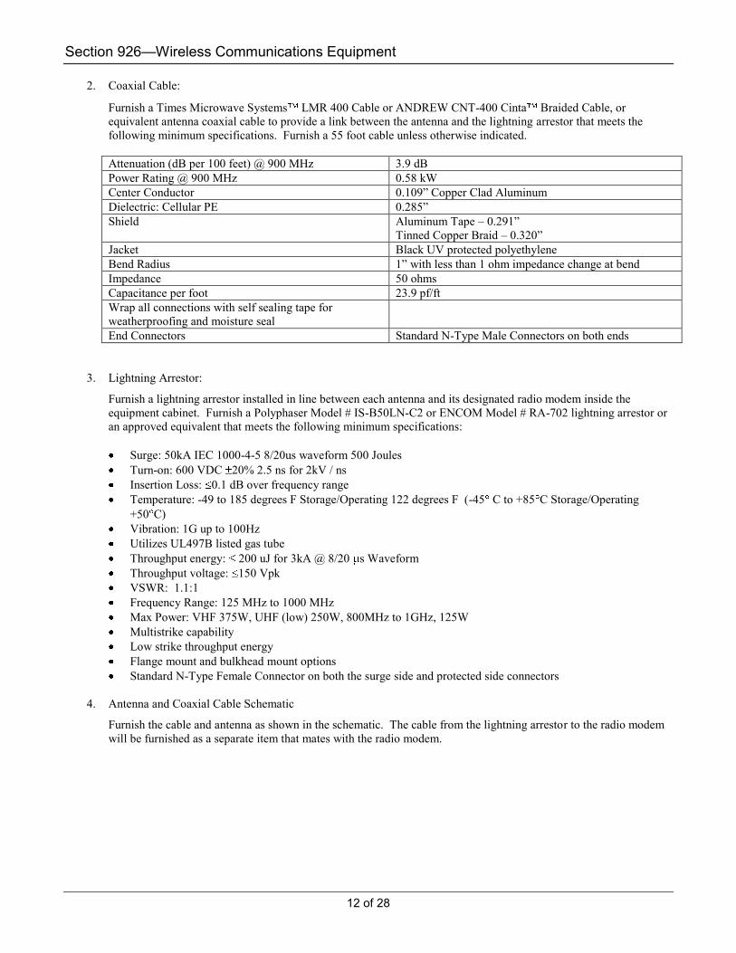
2. Coaxial Cable:
Furnish a Times Microwave Systems LMR 400 Cable or ANDREW CNT-400 Cinta Braided Cable, or
equivalent antenna coaxial cable to provide a link between the antenna and the lightning arrestor that meets the
following minimum specifications. Furnish a 55 foot cable unless otherwise indicated.
Attenuation (dB per 100 feet) @ 900 MHz 3.9 dB
Power Rating @ 900 MHz 0.58 kW
Center Conductor 0.109‖ Copper Clad Aluminum
Dielectric: Cellular PE 0.285‖
Shield Aluminum Tape – 0.291‖
Tinned Copper Braid – 0.320‖
Jacket Black UV protected polyethylene
Bend Radius 1‖ with less than 1 ohm impedance change at bend
Impedance 50 ohms
Capacitance per foot 23.9 pf/ft
Wrap all connections with self sealing tape for
weatherproofing and moisture seal
End Connectors Standard N-Type Male Connectors on both ends
3. Lightning Arrestor:
Furnish a lightning arrestor installed in line between each antenna and its designated radio modem inside the
equipment cabinet. Furnish a Polyphaser Model # IS-B50LN-C2 or ENCOM Model # RA-702 lightning arrestor or
an approved equivalent that meets the following minimum specifications:
Surge: 50kA IEC 1000-4-5 8/20us waveform 500 Joules
Turn-on: 600 VDC 20% 2.5 ns for 2kV / ns
Insertion Loss: 0.1 dB over frequency range
Temperature: -49 to 185 degrees F Storage/Operating 122 degrees F (-45 C to +85 C Storage/Operating
+50 C)
Vibration: 1G up to 100Hz
Utilizes UL497B listed gas tube
Throughput energy: 200 uJ for 3kA @ 8/20 s Waveform
Throughput voltage: 150 Vpk
VSWR: 1.1:1
Frequency Range: 125 MHz to 1000 MHz
Max Power: VHF 375W, UHF (low) 250W, 800MHz to 1GHz, 125W
Multistrike capability
Low strike throughput energy
Flange mount and bulkhead mount options
Standard N-Type Female Connector on both the surge side and protected side connectors
4. Antenna and Coaxial Cable Schematic
Furnish the cable and antenna as shown in the schematic. The cable from the lightning arrestor to the radio modem
will be furnished as a separate item that mates with the radio modem.

Section 926—Wireless Communications Equipment
13 of 28
B. Fabrication
General Provisions 101 through 150.
C. Acceptance
General Provisions 101 through 150.
D. Materials Warranty
Provide all manufacturers’ warranties and guarantees for all signal equipment items listed in this document as well as
any signal equipment listed in the plans, except for state supplied equipment.
Ensure that warranties and guarantees are consistent with those provided as customary trade practices; or as otherwise
specified in the plans, Standard Specifications, Supplemental Specifications or Special Provisions.
Ensure that manufacturer’s and supplier’s warranties and guarantees are transferable to the agency or user that is
responsible for traffic signal maintenance, are continuous throughout their duration and state that they are subject to
such transfer.
Ensure equipment provided under this specification shall be warranted by the manufacturer to be free from defects in
materials and workmanship for a period of two years from date of receipt or one year from date of acceptance of
installation.
Ensure the manufacturer will repair any faulty equipment during this period at no charge to the Department for parts,
labor or shipping to and from the factory.
926.2.07 Omni Directional Radio Antenna and Connecting Cable
Provide wireless communications antenna with connecting cables including surge protection to the Radio unit.
OR RP SMA FEMALE CONNECTOR
RP SMA MALE CONNECTOR OR
ANTENNA RF PATCH CABLE NOT
INCLUDED WITH ANTENNA

Section 926—Wireless Communications Equipment
14 of 28
A. Requirements
Furnish a Omni directional antenna that will interface with a radio unit. Included with this item are the cables to connect
with the radio unit and surge protection.
1. Omni Directional Antenna
Furnish an omni directional antenna that will allow the system to function as designed. Furnish 3dB Antenex Model
# FG9023 or 6dB Antenex Model # FG9026 antenna or approved equivalent antennas that meet the following
minimum specifications:
Frequency Range 902 – 928 MHz
Nominal Gain Typical gains of 3 or 6 dB (dependent upon gain needed for application)
Termination Standard N-Type Female Connector
Impedance 50 ohms
VSWR 1.5:1
Vertical Beam Width 3 dB – 33 degrees; 6 dB – 17 degrees
Lightening Protection DC Ground
Power Rating, UHF Frequency 100 Watts
Length 3dB – 25” (63 cm) 6dB – 65” (165 cm)
Rated Wind Velocity 125 mph (241 kph)
Shall be of solid, single piece construction
Wrap all connections with self sealing tape for weatherproofing and moisture seal
Minimum separation distance from persons installing and using an active device
9” (23 cm)
Minimum separation distance from other RF sources including radios and antennas
6.5’ (2 meters)
Mount in a vertical direction and limit to vertically polarized RF systems
Furnish mounting hardware to secure the antenna to the metal, concrete, or wood pole, as recommended by the
manufacturer of the antenna and as approved by the Engineer.
2. Coaxial Cable:
Furnish a Times Microwave Systems LMR 400 Cable or ANDREW CNT-400 Cinta Braided Cable, or
equivalent antenna coaxial cable to provide a link between the antenna and the lightning arrestor that meets the
following minimum specifications. Furnish a 55 foot cable unless otherwise indicated.
Attenuation (dB per 100 feet) @ 900 MHz 3.9 dB
Power Rating @ 900 MHz 0.58 kW
Center Conductor 0.109” Copper Clad Aluminum
Dielectric: Cellular PE 0.285”
Shield Aluminum Tape – 0.291” Tinned Copper Braid – 0.320”
Jacket Black UV protected polyethylene
Bend Radius 1” with less than 1 ohm impedance change at bend
Impedance 50 ohms
Capacitance per foot 23.9 pf/ft
Wrap all connections with self sealing tape for weatherproofing and moisture seal
End Connectors Standard N-Type Male Connectors on both ends

Section 926—Wireless Communications Equipment
15 of 28
3. Lightning Arrestor:
Furnish a lightning arrestor installed in line between each antenna and its designated radio modem inside the
equipment cabinet. Furnish a Polyphaser Model # IS-B50LN-C2 or ENCOM Model # RA-702 lightning arrestor or
an approved equivalent that meets the following minimum specifications:
Surge: 50kA IEC 1000-4-5 8/20us waveform 500 Joules
Turn-on: 600 VDC 20% 2.5 ns for 2kV / ns
Insertion Loss: 0.1 dB over frequency range
Temperature: -49 to 185 degrees F Storage/Operating 122 degrees F (-45 C to +85 C
Storage/Operating +50 C)
Vibration: 1G up to 100Hz
Utilizes UL497B listed gas tube
Throughput energy: 200 uJ for 3kA @ 8/20 s Waveform
Throughput voltage: 150 Vpk
VSWR: 1.1:1
Frequency Range: 125 MHz to 1000 MHz
Max Power: VHF 375W, UHF (low) 250W, 800MHz to 1GHz, 125W
Multistrike capability
Low strike throughput energy
Flange mount and bulkhead mount options
Standard N-Type Female Connector on both the surge side and protected side connectors
4. Antenna and Coaxial Cable Schematic:
Furnish the cable and antenna as shown in the schematic. The cable from the lightning arrestor to the radio modem
will be furnished as a separate item that mates with the radio modem.
OR RP SMA FEMALE CONNECTOR
RP SMA MALE CONNECTOR OR
ANTENNA RF PATCH CABLE NOT
INCLUDED WITH ANTENNA
Section 926—Wireless Communications Equipment
16 of 28
B. Fabrication
General Provisions 101 through 150.
C. Acceptance
General Provisions 101 through 150.
D. Materials Warranty
Provide all manufacturers’ warranties and guarantees for all signal equipment items listed in this document as well as
any signal equipment listed in the plans, except for state supplied equipment.
Ensure that warranties and guarantees are consistent with those provided as customary trade practices; or as otherwise
specified in the plans, Standard Specifications, Supplemental Specifications or Special Provisions.
Ensure that manufacturer’s and supplier’s warranties and guarantees are transferable to the agency or user that is
responsible for traffic signal maintenance, are continuous throughout their duration and state that they are subject to
such transfer.
Ensure equipment provided under this specification shall be warranted by the manufacturer to be free from defects in
materials and workmanship for a period of two years from date of receipt or one year from date of acceptance of
installation.
Ensure the manufacturer will repair any faulty equipment during this period at no charge to the Department for parts,
labor or shipping to and from the factory.
926.2.08 Antenna RF Patch Cable TNC Connector
Provide the connection from a shelf mount radio unit to the lightning arrestor unit for the antenna. This item is required for
configuration of radio units with TNC antenna connectors.
A. Requirements
Furnish a cable 6 feet long with the appropriate connections. The cable shall have a Reverse Polarity TNC Male
connector on one end for connecting to a shelf mount radio unit and a Standard N Type Male connector on the other end
for attaching to the antenna lightning arrestor. The cable shall be labeled as to its function.
1. Cable
The cable shall use RG 58 COAX.
B. Fabrication
General Provisions 101 through 150.
C. Acceptance
General Provisions 101 through 150.
D. Materials Warranty
Provide all manufacturers’ warranties and guarantees for all signal equipment items listed in this document as well as
any signal equipment listed in the plans, except for state supplied equipment.
Ensure that warranties and guarantees are consistent with those provided as customary trade practices; or as otherwise
specified in the plans, Standard Specifications, Supplemental Specifications or Special Provisions.
Ensure that manufacturer’s and supplier’s warranties and guarantees are transferable to the agency or user that is
responsible for traffic signal maintenance, are continuous throughout their duration and state that they are subject to
such transfer.
Ensure equipment provided under this specification shall be warranted by the manufacturer to be free from defects in
materials and workmanship for a period of two years from date of receipt or one year from date of acceptance of
installation.
Ensure the manufacturer will repair any faulty equipment during this period at no charge to the Department for parts,
labor or shipping to and from the factory.

Section 926—Wireless Communications Equipment
17 of 28
926.2.09 Antenna RF Patch Cable SMA Connector
Provide the connection from a rack mount radio unit to the lightning arrestor unit for the antenna. This item is required for
configuration of radio units with SMA antenna connectors.
A. Requirements
Furnish a cable 6 feet long with the appropriate connections. The cable shall have a Reverse Polarity SMA Male
connector on one end for connecting to a shelf mount radio unit and a Standard N Type Male connector on the other end
for attaching to the antenna lightning arrestor. The cable shall be labeled as to its function.
1. Cable
The cable shall use RG 58 COAX.
B. Fabrication
General Provisions 101 through 150.
C. Acceptance
General Provisions 101 through 150.
D. Materials Warranty
Provide all manufacturers’ warranties and guarantees for all signal equipment items listed in this document as well as
any signal equipment listed in the plans, except for state supplied equipment.
Ensure that warranties and guarantees are consistent with those provided as customary trade practices; or as otherwise
specified in the plans, Standard Specifications, Supplemental Specifications or Special Provisions.
Ensure that manufacturer’s and supplier’s warranties and guarantees are transferable to the agency or user that is
responsible for traffic signal maintenance, are continuous throughout their duration and state that they are subject to
such transfer.
Ensure equipment provided under this specification shall be warranted by the manufacturer to be free from defects in
materials and workmanship for a period of two years from date of receipt or one year from date of acceptance of
installation.
Ensure the manufacturer will repair any faulty equipment during this period at no charge to the Department for parts,
labor or shipping to and from the factory.
926.2.10 Antenna Power Divider
Provide item splitting the radio antenna connection for locations where two antennas are required with one radio unit. This
item is to include a ―T‖ Splitter and two cables.
A. Requirements
Furnish a ―T‖ Splitter for providing two separate antenna connections to one radio unit. The Splitter shall be
weatherproof and provide for low insertion loss. All connectors will be Type N Female. The splitter shall be furnished
with two 6 foot cables of Times Microwave Systems LMR 400 Cable or equal. The cables will provide Type N Male
connectors on either end. These cables will provide a link between the antennas and the splitter.
1. Power Divider
Furnish a two way weatherproof splitter (Telewave Model #ANTPD29 or approved equal) with the following
characteristics.
Power Division: 2-Way
Frequency = .900 – 1100 MHz
Dimensions: less than 5‖ x 2.5‖
Insertion Loss: < 0.22 dB

Section 926—Wireless Communications Equipment
18 of 28
Max Input Power: 500 Watts
Impedance: 50 Ohm
VSWR ref. to 50 Ohm (max): 1.3:1
Connectors: N Female
2. Cables
Furnish two Times Microwave Systems LMR 400 Cable or ANDREW CNT-400 Cinta Braided Cable, or
equivalent antenna coaxial cable to provide a link between the antenna and the lightning arrestor that meets the
following minimum specifications:
Attenuation (dB per 100 feet) @ 900 MHz 3.9 dB
Power Rating @ 900 MHz 0.58 kW
Center Conductor 0.109” Copper Clad Aluminum
Dielectric: Cellular PE 0.285”
Shield Aluminum Tape – 0.291” Tinned Copper Braid – 0.320”
Jacket Black UV protected polyethylene
Bend Radius 1” with less than 1 ohm impedance change at bend
Impedance 50 ohms
Capacitance per foot 23.9 pf/ft
Wrap all connections with self sealing tape for weatherproofing and moisture seal
End Connectors Standard N-Type Male Connectors on both ends
B. Fabrication
General Provisions 101 through 150.
“T” SPLITTER
SECOND ANTENNA
COAXIAL CABLE TIMES
MICROWAVE SYSTEMS
LMR 400
EXISTING
EXISTING
STANDARD N-TYPE
FEMALE CONNECTORS
COAXIAL CABLE TIMES
MICROWAVE SYSTEMS LMR
400

Section 926—Wireless Communications Equipment
19 of 28
C. Acceptance
General Provisions 101 through 150.
D. Materials Warranty
Provide all manufacturers’ warranties and guarantees for all signal equipment items listed in this document as well as
any signal equipment listed in the plans, except for state supplied equipment.
Ensure that warranties and guarantees are consistent with those provided as customary trade practices; or as otherwise
specified in the plans, Standard Specifications, Supplemental Specifications or Special Provisions.
Ensure that manufacturer’s and supplier’s warranties and guarantees are transferable to the agency or user that is
responsible for traffic signal maintenance, are continuous throughout their duration and state that they are subject to
such transfer.
Ensure equipment provided under this specification shall be warranted by the manufacturer to be free from defects in
materials and workmanship for a period of two years from date of receipt or one year from date of acceptance of
installation.
Ensure the manufacturer will repair any faulty equipment during this period at no charge to the Department for parts,
labor or shipping to and from the factory.
926.2.11 Configuration Cable Radio Unit to Computer DB9 Serial
Provide cable for serial connection from a radio unit to a computer that allows the computer to configure the radio unit. This
item is required to configure radio units with DB9 serial connections.
A. Requirements
Furnish a cable 6 feet long with the appropriate connections. The cable shall have a DB 9M connector on the end that
mates with the radio unit and a DB9F connector on the end that mates with the computer. The cable shall provide the
appropriate signal connections to allow the radio unit to be programmed by the computer using the supplied
configuration software. The cable shall be labeled as to its function and each end of the connector shall be labeled.
The cable shall use 22 AWG stranded cable that is color coded for connections.
B. Fabrication
General Provisions 101 through 150.
C. Acceptance
General Provisions 101 through 150.
D. Materials Warranty
Provide all manufacturers’ warranties and guarantees for all signal equipment items listed in this document as well as
any signal equipment listed in the plans, except for state supplied equipment.
Ensure that warranties and guarantees are consistent with those provided as customary trade practices; or as otherwise
specified in the plans, Standard Specifications, Supplemental Specifications or Special Provisions.
Ensure that manufacturer’s and supplier’s warranties and guarantees are transferable to the agency or user that is
responsible for traffic signal maintenance, are continuous throughout their duration and state that they are subject to
such transfer.
Ensure equipment provided under this specification shall be warranted by the manufacturer to be free from defects in
materials and workmanship for a period of two years from date of receipt or one year from date of acceptance of
installation.
Ensure the manufacturer will repair any faulty equipment during this period at no charge to the Department for parts,
labor or shipping to and from the factory.

Section 926—Wireless Communications Equipment
20 of 28
926.2.12 Configuration Cable Radio Unit (RJ 12) to Computer DB9 Serial
Provide the serial connection cable from a radio unit to a computer and allows the computer to configure the radio unit. This
item is required to configure radio units with RJ 12 programming connectors.
A. Requirements
Furnish a cable 6 feet long with the appropriate connections. The cable shall have a RJ 12 connector on the end that
mates with the radio unit and a DB9F connector on the end that mates with the computer. The cable shall provide the
appropriate signal connections to allow the radio unit to be programmed by the computer using the supplied
configuration software. The cable shall be labeled as to its function and each end of the connector shall be labeled.
The cable shall use 22 AWG stranded cable that is color coded for connections.
B. Fabrication
General Provisions 101 through 150.
C. Acceptance
General Provisions 101 through 150.
D. Materials Warranty
Provide all manufacturers’ warranties and guarantees for all signal equipment items listed in this document as well as
any signal equipment listed in the plans, except for state supplied equipment.
Ensure that warranties and guarantees are consistent with those provided as customary trade practices; or as otherwise
specified in the plans, Standard Specifications, Supplemental Specifications or Special Provisions.
Ensure that manufacturer’s and supplier’s warranties and guarantees are transferable to the agency or user that is
responsible for traffic signal maintenance, are continuous throughout their duration and state that they are subject to
such transfer.
Ensure equipment provided under this specification shall be warranted by the manufacturer to be free from defects in
materials and workmanship for a period of two years from date of receipt or one year from date of acceptance of
installation.
Ensure the manufacturer will repair any faulty equipment during this period at no charge to the Department for parts,
labor or shipping to and from the factory.
926.2.13 Connecting Cable (RS 232) from Radio Unit (DB9M) to 2070 7A Comm Module
Provide the serial connection cable from a radio unit to a 2070 Controller 7A module.
A. Requirements
Furnish a cable 6 feet long with the appropriate connections. The cable shall have a DB 9 Male Connectors on both
ends. The cable shall provide the appropriate signal connections to allow the radio unit to communicate with a 2070
controller using a 7A communications modules. The cable shall be labeled as to its function and each end of the
connector shall be labeled.
The cable shall use 22 AWG stranded cable that is color coded for connections.
B. Fabrication
General Provisions 101 through 150.
C. Acceptance
General Provisions 101 through 150.
D. Materials Warranty
Provide all manufacturers’ warranties and guarantees for all signal equipment items listed in this document as well as
any signal equipment listed in the plans, except for state supplied equipment.

Section 926—Wireless Communications Equipment
21 of 28
Ensure that warranties and guarantees are consistent with those provided as customary trade practices; or as otherwise
specified in the plans, Standard Specifications, Supplemental Specifications or Special Provisions.
Ensure that manufacturer’s and supplier’s warranties and guarantees are transferable to the agency or user that is
responsible for traffic signal maintenance, are continuous throughout their duration and state that they are subject to
such transfer.
Ensure equipment provided under this specification shall be warranted by the manufacturer to be free from defects in
materials and workmanship for a period of two years from date of receipt or one year from date of acceptance of
installation.
Ensure the manufacturer will repair any faulty equipment during this period at no charge to the Department for parts,
labor or shipping to and from the factory.
926.2.14 Connecting Cable (RS 232) from existing Fiber Modem Cable to Radio Unit to 2070 7A Comm Module
Provide the serial connection cable from an existing serial cable that connects a fiber modem to a 2070 Controller 7A
module. This cable connects the fiber modem with a radio unit and also to a 2070 7A module. The cable has 3 connectors.
A. Requirements
Furnish a cable 6 feet long between all connectors with the appropriate connections. The cable shall have two DB 9
Male Connectors and one DB 9 Female connector. The cable shall provide the appropriate signal connections to allow
the radio unit to communicate with a 2070 controller using a 7A communications module and support the serial
communications with an existing fiber modem. This cable is intended to be used at locations where fiber
communications end. The cable shall be labeled as to its function and each of the three connectors shall be labeled. The
cable is a ―Y‖ configuration.
The cable shall use 22 AWG stranded cable that is color coded for connections.
B. Fabrication
General Provisions 101 through 150.
C. Acceptance
General Provisions 101 through 150.
D. Materials Warranty
Provide all manufacturers’ warranties and guarantees for all signal equipment items listed in this document as well as
any signal equipment listed in the plans, except for state supplied equipment.
Ensure that warranties and guarantees are consistent with those provided as customary trade practices; or as otherwise
specified in the plans, Standard Specifications, Supplemental Specifications or Special Provisions.
Ensure that manufacturer’s and supplier’s warranties and guarantees are transferable to the agency or user that is
responsible for traffic signal maintenance, are continuous throughout their duration and state that they are subject to
such transfer.
Ensure equipment provided under this specification shall be warranted by the manufacturer to be free from defects in
materials and workmanship for a period of two years from date of receipt or one year from date of acceptance of
installation.
Ensure the manufacturer will repair any faulty equipment during this period at no charge to the Department for parts,
labor or shipping to and from the factory.
926.2.15 Connecting Cable from Radio Unit to existing FSK Field Wires
Provide an FSK connection cable to the field communication wires from the radio unit.

Section 926—Wireless Communications Equipment
22 of 28
A. Requirements
Furnish a cable 6 feet long with the appropriate connections. The cable shall have an RJ -22 connector on one end with 4
―pig tails‖ on the other end. The cable shall provide the appropriate signal connections to allow the radio unit to
communicate with a 4 wire or two wire FSK communications network. Each wire shall be color coded and labeled as to
its pin number. The wire ends shall be unterminated.
The cable shall use 22 AWG stranded cable that is color coded for connections.
B. Fabrication
General Provisions 101 through 150.
C. Acceptance
General Provisions 101 through 150.
D. Materials Warranty
Provide all manufacturers’ warranties and guarantees for all signal equipment items listed in this document as well as
any signal equipment listed in the plans, except for state supplied equipment.
Ensure that warranties and guarantees are consistent with those provided as customary trade practices; or as otherwise
specified in the plans, Standard Specifications, Supplemental Specifications or Special Provisions.
Ensure that manufacturer’s and supplier’s warranties and guarantees are transferable to the agency or user that is
responsible for traffic signal maintenance, are continuous throughout their duration and state that they are subject to
such transfer.
Ensure equipment provided under this specification shall be warranted by the manufacturer to be free from defects in
materials and workmanship for a period of two years from date of receipt or one year from date of acceptance of
installation.
Ensure the manufacturer will repair any faulty equipment during this period at no charge to the Department for parts,
labor or shipping to and from the factory.
926.2.16 Connecting Cable (RS 232) from Existing Fiber Modem Cable to 2070 Mount Radio Unit
Provide the serial connection cable from an existing fiber modem cable that was connected to a 2070 7A module; to a 2070
mount radio unit.
A. Requirements
Furnish a cable 6 feet long with the appropriate connections. The cable shall have a DB 9 Male Connector on one end to
mate with a 2070 Mount Radio Unit and a DB 9 Female Connector on the other end to mate with an existing fiber
modem cable. The cable shall provide the appropriate signal connections to allow the radio unit to communicate with a
2070 mounted radio unit. The cable shall be labeled as to its function and each end of the connector shall be labeled.
The cable shall use 22 AWG stranded cable that is color coded for connections.
B. Fabrication
General Provisions 101 through 150.
C. Acceptance
General Provisions 101 through 150.
D. Materials Warranty
Provide all manufacturers’ warranties and guarantees for all signal equipment items listed in this document as well as
any signal equipment listed in the plans, except for state supplied equipment.
Ensure that warranties and guarantees are consistent with those provided as customary trade practices; or as otherwise
specified in the plans, Standard Specifications, Supplemental Specifications or Special Provisions.
Ensure that manufacturer’s and supplier’s warranties and guarantees are transferable to the agency or user that is
responsible for traffic signal maintenance, are continuous throughout their duration and state that they are subject to
such transfer.

Section 926—Wireless Communications Equipment
23 of 28
Ensure equipment provided under this specification shall be warranted by the manufacturer to be free from defects in
materials and workmanship for a period of two years from date of receipt or one year from date of acceptance of
installation.
Ensure the manufacturer will repair any faulty equipment during this period at no charge to the Department for parts,
labor or shipping to and from the factory.
926.2.17 Shelf Mount Spread Spectrum Wireless Radio Transceiver with Ethernet Interface
Provide wireless communications point to point or point to multipoint to support Ethernet communications. This unit is to
be supplied with power supply and configuration software.
A. Requirements
Furnish a spread spectrum wireless radio unit with all necessary hardware (excluding antennae) to provide a data link
between field devices (i.e. Traffic Signal Controllers, Dynamic Message Signs, etc.). Radio unit will use IP/Ethernet or
Serial communications channel between two ―line-of-sight‖ antennas using license free, frequency hopping spread
spectrum technology operating in the 902-928 MHz frequency band.
1. 900MHz Wireless Radio Unit
Furnish license free 902 – 928 MHz radio modems with configuration and diagnostic software. Design radio
modems to work in ―point-to-point‖, and ―point-to-multipoint‖ configurations. Ensure the spread spectrum wireless
radio meets the following minimum requirements:
License free (ISM) Spread Spectrum radio band (902 – 928 MHz)
Frequency Hopping Spread Spectrum Technology (Direct Sequence Spread Spectrum Technology is not
acceptable)
Selectable Operating modes:
Access Point, Dual Gateway, Remote Serial, Remote Ethernet
Programmable Radio Frequency (RF) output levels of 1mW, 10mW, 100mW, or 1 Watt
128-bit data encryption
DB9-F connectors for RS-232 multiple Serial ports
1200 bps to 512 Kbps, with 8 or 9 bit format
Encapsulation over IP for serial devices (IE. Traffic controllers)
RJ-45 Ethernet Data Port, 10/100BaseT, IEEE 802.3 compliant
256/512kbps data throughput
Spanning Tree, IP(DHCP, ICMP, UDP, TCP, ARP)
Receiver Sensitivity
–110dBm @ 10^-6 BER, Serial
–100dBm @ 10^-6 BER, Ethernet
Management Software
Supports SNMP, MIBII
Telnet, HTTP, Local console (ControlPAK™)
Built-in store-and-forward (single radio repeater – no back to back radio set-ups are allowed to accomplish this
function)
Antenna port: Reverse Polarity - Threaded Normalized Connector-Female (RP TNC-F) antenna connector
Front panel LED indicators
Power
Transmit Data
Receive Data
Data Port Indicators
Operating temperature of –40 to +176 degrees F (-40 to +80 degrees C) at 0 to 95% Humidity
Power supply requirements
Wall Adaptor: 120 VAC UL/CSA wall cube plug in module with 12 VDC, 1 Amp, nominal output.
Shelf Mounted Design not to exceed 4.5‖ Long x 3.75‖ Wide x 1.75‖ High

Section 926—Wireless Communications Equipment
24 of 28
Ensure that the wireless radio unit is a fully functional field device (i.e. controller does not require any field device
modifications with regards to hardware or software).
2. Configuration Software
Furnish units with a Window Based software program that uses a GUI (Graphical User Interface) to provide ―remote
programming, radio configuration, remote maintenance, diagnostics and spectrum analyzer‖ features. Provide no cost
configuration and diagnostic software that can be upgraded in the future at no additional charge.
Ensure the radio modem is configurable from a single location (i.e. master radio location) via supplied software (no extra
cost). Furnish software supplied with drivers to allow easy set-up with all industry standard traffic signal controllers,
including 2070 controllers containing custom software written specifically for the Georgia Department of Transportation.
Ensure the supplied software contains pre-written drivers for industry standard radar and video detection packages and
Dynamic Message Sign controllers.
B. Fabrication
General Provisions 101 through 150.
C. Acceptance
General Provisions 101 through 150.
D. Materials Warranty
Provide all manufacturers’ warranties and guarantees for all signal equipment items listed in this document as well as
any signal equipment listed in the plans, except for state supplied equipment.
Ensure that warranties and guarantees are consistent with those provided as customary trade practices; or as otherwise
specified in the plans, Standard Specifications, Supplemental Specifications or Special Provisions.
Ensure that manufacturer’s and supplier’s warranties and guarantees are transferable to the agency or user that is
responsible for traffic signal maintenance, are continuous throughout their duration and state that they are subject to
such transfer.
Ensure equipment provided under this specification shall be warranted by the manufacturer to be free from defects in
materials and workmanship for a period of two years from date of receipt or one year from date of acceptance of
installation.
Ensure the manufacturer will repair any faulty equipment during this period at no charge to the Department for parts,
labor or shipping to and from the factory.
926.2.18 Spread Spectrum Wireless Radio Site Survey kit Provide all of the necessary equipment to test the ability to use frequency hopping spread spectrum wireless communications
at a site specific location. The Site Survey Kit is to come complete with a rugged carrying case for weatherproofing and
transportation purposes.
A. Requirements
Furnish a spread spectrum wireless radio site survey kit in a weather proof carrying case. Included in the kit are:
Mounting Hardware, AC Charger, DC Charging Cable, Configuration and Diagnostic Software, Host Radio, Remote
Radio, Antenna Masts, RF Coaxial Cable, 2 Yagi antennas, and 1 Omni Directional Antenna. The site survey kit is to
allow the obtainment of the following results for the site specific locations: Signal Strength (dBm), Fade margin (dB),
S/N Ratio, Data integrity (poll test), and a Complete Frequency Spectrum Scan.
1. 900MHz Wireless Radio Units (Host and Remote)
Furnish license free 902 – 928 MHz radio modems with configuration software. Design radio modems to work in
―point-to-point‖, ―point-to-multipoint‖ ―multipoint-to-point‖, and ―multipoint-to-multipoint‖ configurations. Ensure
the spread spectrum wireless radio meets the following minimum requirements:
License free (ISM) Spread Spectrum radio band (902 – 928 MHz)

Section 926—Wireless Communications Equipment
25 of 28
Frequency Hopping Spread Spectrum Technology (Direct Sequence Spread Spectrum Technology is not
acceptable)
Bi-Directional, Full Duplex
Programmable Radio Frequency (RF) output levels of 1mW, 10mW, 100mW, or 1 Watt
RS-232 interface capable of operating from 1200 bps to 115.2 Kbps, with 8 or 9 bit format
DB9-F connector for RS-232 port
16 bit Cyclic Redundancy Check (CRC) error checking with auto re-transmit
Built-in store-and-forward (single radio repeater – no back to back radios set-ups are allowed to accomplish
this function)
32 Bit encryption
Receiver Sensitivity of –110dBm @ 10^-6 BER
Antenna port: N-Female antenna connector
LED indicators
Power
Low Battery
RSSI
Operating temperature of –40 to +176 degrees F (-40 to +80 degrees C) at 0 to 95% Humidity
Power supply requirements
12 Volt Rechargeable Battery
Typical current draw of no greater than 355 mA when powered with 12 VDC input, and transmitting 1
Watt of RF output power.
Radio Sleep mode with a maximum current draw of 1 A
Mounted in a rugged carrying case Design not to exceed 10.5‖ Long x 11‖ Wide x 5‖ High
ON/OFF Switch and 12 VDC Charge Input
2. Site Survey Carrying Case
Furnish a carrying case for the site survey kit. The carrying case is to contain the radio modems,, antennas,
mounting hardware, coaxial cables, and assorted cables. Overall dimensions of the carrying case are not to exceed
21‖ x 33‖ x 11‖ ands weight not to exceed 60lbs.
3. Configuration Software
Furnish units with a Window Based software program that uses a GUI (Graphical User Interface) to provide
―remote programming, radio configuration, remote maintenance, diagnostics and spectrum analyzer‖ features.
Provide no cost configuration and diagnostic software that can be upgraded in the future at no additional charge.
Ensure the radio modem is configurable from a single location (i.e. master radio location) via supplied software (no
extra cost). Furnish software supplied with drivers to allow easy set-up with all industry standard traffic signal
controllers, including 2070 controllers containing custom software written specifically for the Georgia Department
of Transportation. Ensure the supplied software contains pre-written drivers for industry standard radar and video
detection packages and Dynamic Message Sign controllers.
4. RF Coaxial Cables
Furnish a Times Microwave Systems LMR 400 Cable or ANDREW CNT-400 Cinta Braided Cable, or
equivalent antenna coaxial cable to provide a link between the antenna and the portable radio units that meets the
following minimum specifications:
Attenuation (dB per 100 feet) @ 900 MHz 3.9 dB
Power Rating @ 900 MHz 0.58 kW
Center Conductor 0.109” Copper Clad Aluminum
Dielectric: Cellular PE 0.285”
Shield Aluminum Tape – 0.291” Tinned Copper Braid – 0.320”
Jacket Black UV protected polyethylene

Section 926—Wireless Communications Equipment
26 of 28
Bend Radius 1” with less than 1 ohm impedance change at bend
Impedance 50 ohms
Capacitance per foot 23.9 pf/ft
Wrap all connections with self sealing tape for weatherproofing and moisture seal
End Connectors Standard N-Type Male Connectors on both end
5. Yagi Antenna
Furnish 2 Cushcraft Model # PC906N antennas or an approved equivalent antennas that meets the following
minimum specifications:
Frequency Range 896 – 940 MHz
Nominal Gain 8.5 dBd or 10.64 dBi
Front to Back Ratio 18 dB
Horizontal Beamwidth (at half power points) 65 degree
Vertical Beamwidth (at half power points) 55 degree
Power Rating, UHF Frequency 200 Watts
Lightning Protection DC Ground
Termination Coaxial pigtail with a Standard N-Type Female Connector
Length 24” (612 mm)
Width @896 MHz 6.4” (163 mm)
Rated Wind Velocity 125 mph (200 kph)
Rated Wind Velocity (with .5 inch radial ice)
100 mph (161 kph)
Lateral thrust @ 100 mph Wind Velocity 38 lbs. (17 Grams)
Projected Wind Surface Area (flat plane equivalent)
0.26 ftsq. (0.024 msq)
Number Elements 6 for a nominal 9 dB gain, 9 for a nominal 13 dB gain
Allows for Vertical or Horizontal polarization
Wrap all connections with self sealing tape for weatherproofing and moisture seal
Minimum separation distance from persons installing and using an active device
9” (23 cm)
Minimum separation distance from other RF sources including radios and antennas
6.5’ (2 m)
Welded construction
Furnish mounting hardware to temporarily secure the antenna to the metal, wood or concrete pole (included with the
kit).
6. Omni Directional Antenna
Furnish an omni directional antenna that will allow the system to function as designed. Furnish 3dB Antenex Model
# FG9023 or 6dB Antenex Model # FG9026 antenna or approved equivalent antennas that meet the following
minimum specifications:
Frequency Range 902 – 928 MHz
Nominal Gain Typical gains of 3 or 6 dB (dependent upon gain needed for application)
Termination Standard N-Type Female Connector

Section 926—Wireless Communications Equipment
27 of 28
Impedance 50 ohms
VSWR 1.5:1
Vertical Beam Width 3 dB – 33 degrees; 6 dB – 17 degrees
Lightening Protection DC Ground
Power Rating, UHF Frequency 100 Watts
Length 3dB – 25” (63 cm) 6dB – 65” (165 cm)
Rated Wind Velocity 125 mph (241 kph)
Shall be of solid, single piece construction
Wrap all connections with self sealing tape for weatherproofing and moisture seal
Minimum separation distance from persons installing and using an active device
9” (23 cm)
Minimum separation distance from other RF sources including radios and antennas
6.5’ (2 meters)
Mount in a vertical direction and limit to vertically polarized RF systems
Furnish mounting hardware to temporarily secure the antenna to the metal, concrete, or wood pole, as recommended
by the manufacturer of the antenna and as approved by the Engineer.
B. Fabrication
General Provisions 101 through 150.
C. Acceptance
General Provisions 101 through 150.
D. Materials Warranty
Provide all manufacturers’ warranties and guarantees for all signal equipment items listed in this document as well as
any signal equipment listed in the plans, except for state supplied equipment.
Ensure that warranties and guarantees are consistent with those provided as customary trade practices; or as otherwise
specified in the plans, Standard Specifications, Supplemental Specifications or Special Provisions.
Ensure that manufacturer’s and supplier’s warranties and guarantees are transferable to the agency or user that is
responsible for traffic signal maintenance, are continuous throughout their duration and state that they are subject to
such transfer.
Ensure equipment provided under this specification shall be warranted by the manufacturer to be free from defects in
materials and workmanship for a period of two years from date of receipt or one year from date of acceptance of
installation.
Ensure the manufacturer will repair any faulty equipment during this period at no charge to the Department for parts,
labor or shipping to and from the factory.
926.2.19 Spread Spectrum Wireless Radio Training
Provide training as required herein. Include with training all supplies, equipment, materials, handouts, travel, and subsistence
necessary to conduct the training. Provide training agenda at least two months prior to requesting to conduct training.
A. Requirements
Provide installation, operations and maintenance training for up to 12 people. Include in this training both classroom
training and hands-on-training. Limit in-shop training and field training to group sizes to 4 people at a time. Conduct
training in half-day sessions. Two half-day sessions may be held on the same day. The total training shall consist of at
least 6 hours of training for each participant. Equipment provider is to determine the specific length of the training
course but it may not be less than 6 hours. Provide a course content which includes as a minimum, the following:
General theory of operation

Section 926—Wireless Communications Equipment
28 of 28
Operation of wireless communications equipment
Programming of unit
Conducting a Site Survey
Discussion of warranties
Hands-on use of equipment
Request to conduct training at least thirty days prior to first training session. With request to conduct training provide a
detailed course outline with training materials to be used. Arrange for and submit location of training for approval.
Office of Traffic Safety and Design