dell emc vmax all flash and vmax3 reliability availability ... · pdf filesoftware features of...
TRANSCRIPT
WHITE PAPER
DELL EMC® VMAX ALL FLASH™ AND VMAX3™ RELIABILITY, AVAILABILITY, AND SERVICEABILITY
Technical Note
ABSTRACT
This technical note explains the Reliability, Availability, and Serviceability hardware and
software features of Dell EMC VMAX All Flash and VMAX3 arrays.
May, 2017

2
© 2017 Dell Inc. or its subsidiaries. All Rights Reserved. Dell, EMC and other trademarks are trademarks of Dell Inc. or its subsidiaries.
Other trademarks may be trademarks of their respective owners. Reference Number: H13807.7
3
TABLE OF CONTENTS
ABSTRACT ................................................................................................................................1
EXECUTIVE SUMMARY ...........................................................................................................6
Audience ........................................................................................................................................... 7
INTRODUCTION ........................................................................................................................7
REMOTE SUPPORT ..................................................................................................................7
Supportability through the management module control station ........................................................ 8
Secure Service Credential (SSC), Secured by RSA .......................................................................... 8
ERROR DETECTION .................................................................................................................8
Block CRC error checks .................................................................................................................... 9
Data integrity checks ......................................................................................................................... 9
Drive monitoring and correction ......................................................................................................... 9
Physical memory error verification and error correction .................................................................... 9
RELIABLE COMPONENTS .......................................................................................................9
COMPONENT-LEVEL REDUNDANCY.................................................................................. 10
Redundant engine components....................................................................................................... 10
Redundant director boards ......................................................................................................................... 11
Management module control stations and management modules ............................................................. 12
Management module control station (MMCS) ............................................................................................ 12
Management module (MM) ......................................................................................................................... 13
Flash I/O module ......................................................................................................................................... 13
Front-end I/O module .................................................................................................................................. 13
Back-end I/O module .................................................................................................................................. 13
InfiniBand (IB) module ................................................................................................................................ 13
Shared physical memory ............................................................................................................................ 13
Global memory technology overview .......................................................................................................... 13
Physical port numbering ............................................................................................................................. 14
Logical port numbering ............................................................................................................................... 14
Channel front-end redundancy ........................................................................................................ 15
SAS back-end redundancy .............................................................................................................. 15
Redundant back-end director connectivity .................................................................................................. 15
Redundant cable paths ............................................................................................................................... 16
Redundant drive paths ................................................................................................................................ 16
4
Point-to-point back-end ............................................................................................................................... 16
Drive Array Enclosure (DAE) ........................................................................................................... 16
DAE components ........................................................................................................................................ 16
Fault zones for DAEs .................................................................................................................................. 17
Dual-initiator feature .................................................................................................................................... 18
DYNAMIC VIRTUAL MATRIX ................................................................................................ 19
Internal environmental Ethernet connectivity ................................................................................... 19
REDUNDANT POWER SUBSYSTEM .................................................................................... 20
Battery backup unit modules ........................................................................................................... 20
Vaulting ........................................................................................................................................... 20
Vault triggers ................................................................................................................................... 20
Internal availability triggers ......................................................................................................................... 20
External availability triggers ........................................................................................................................ 21
Power-down operation .................................................................................................................... 21
Power-up operation ......................................................................................................................... 21
DATA PROTECTION METHODS ........................................................................................... 21
RAID 1 (Mirroring) ........................................................................................................................... 22
RAID 5 ............................................................................................................................................. 22
RAID 6 ............................................................................................................................................. 22
Local RAID ...................................................................................................................................... 22
Thin provisioning ............................................................................................................................. 23
Drive sparing ................................................................................................................................... 23
Spare Drive Replenishment Process .......................................................................................................... 24
Local replication using TimeFinder .................................................................................................. 25
Remote replication using SRDF ...................................................................................................... 25
SRDF/Cascade and SRDF/Star support ..................................................................................................... 25
SRDF/Metro support ................................................................................................................................... 26
Data at Rest Encryption (D@RE) .................................................................................................... 27
COMPONENT-LEVEL SERVICEABILITY ............................................................................. 27
Flashing rack lights .......................................................................................................................... 28
NONDISRUPTIVE HYPERMAX OS UPGRADES .................................................................. 29
VMAX 250F ............................................................................................................................. 29
VMAX 250F V-Brick ........................................................................................................................ 29
VMAX 250F Back-end ..................................................................................................................... 30
5
VMAX 250F System Power ............................................................................................................. 30
VMAX 250F Serviceability ............................................................................................................... 30
VMAX 950F ............................................................................................................................. 30
VMAX 950F V-Brick ........................................................................................................................ 31
VMAX 950F Back-end ..................................................................................................................... 31
VMAX 950F System Power ............................................................................................................. 32
VMAX 950F Serviceability ............................................................................................................... 32
CONCLUSION ........................................................................................................................ 32
REFERENCES ........................................................................................................................ 32
APPENDIX A: RESILIENCY TESTING ................................................................................. 33
Dell EMC Internal QE Testing ......................................................................................................... 33
On-site Proof-of-Concept Demonstrations ...................................................................................... 33
6
EXECUTIVE SUMMARY
The IT industry has been growing and changing at a rapid pace, with a large area of focus on cloud computing and cloud-like
consumption models. IT organizations are finding that they must be able to cater to both internal and external customers’ storage
needs, while maintaining alignment with the budget that is provided to them.
VMAX All Flash and VMAX3 platforms accommodate all of these needs. They provide a simple, service level-based provisioning model
that changes the way users consume storage, taking the focus away from the back-end configuration steps and allowing them to
concentrate on other key roles.
While simplifying storage consumption is critical, other features also create a powerful platform. Redundant hardware components and
intelligent software architecture deliver extreme performance while also providing high availability levels approaching 6 nines of
availability. This combination provides exceptional reliability, while also leveraging components in new and innovative ways which
decreases the total cost of ownership of each system.
Important functionality such as local and remote replication of data used to deliver business continuity must cope with more data than
ever before, without impacting production activities. Furthermore, at the end of the day, all of these challenges must be met while
continually improving economics.
Highlights include:
Service level-based provisioning: The requirements of a storage consumer revolve around capacity and performance. It is important
for them to have the right amount of capacity to fulfill their needs as well as the proper performance levels. Through service level-based
provisioning HYPERMAX OS gives VMAX3 users the opportunity to select a predefined service level, provision storage to it, and get
the performance they need, without worrying about all of the back-end configurations. VMAX All Flash systems are architected with a
single tier and with the highest possible service level.
Performance: The processing power, memory, and bandwidth deliver high levels of predictable performance. This means providing
the performance to meet the IOPS and MB/s needs of the world’s most demanding applications. HYPERMAX OS also provides the
ability to absorb I/O bursts due to unpredictable workloads, such as end-of-quarter processing and performance intensive ad hoc
queries, while continuing to guarantee consistent application-response times.
Information-centric security, built-in: Integrated RSA technology provides industry-leading, information-centric security to secure
people, infrastructure, and data. Security features reduce risk and protect information. Organizations can authenticate, authorize, and
audit activities on systems and devices.
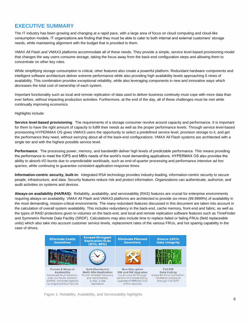
Always-on availability (HA/RAS): Reliability, availability, and serviceability (RAS) features are crucial for enterprise environments
requiring always-on availability. VMAX All Flash and VMAX3 platforms are architected to provide six-nines (99.9999%) of availability in
the most demanding, mission-critical environments. The many redundant features discussed in this document are taken into account in
the calculation of overall system availability. This includes redundancy in the back-end, cache memory, front-end and fabric, as well as
the types of RAID protections given to volumes on the back-end, and local and remote replication software features such as TimeFinder
and Symmetrix Remote Data Facility (SRDF). Calculations may also include time to replace failed or failing FRUs (field replaceable
units) which also take into account customer service levels, replacement rates of the various FRUs, and hot sparing capability in the
case of drives.
Figure 1: Reliability, Availability, and Serviceability highlights
7
VMAX All Flash and VMAX3 have raised customer expectations for high-end storage in terms of availability, performance, replication,
scalability, and management. High-end availability is more than just redundancy; it means nondisruptive operations and upgrades, and
being “always online.” Delivering high-end performance means handling all workloads, predictable or not, under all conditions. High-end
replication means any amount of data anytime and sending it any distance. High-end scalability means more than capacity; it means
having the flexibility to handle any service level or application, cost-effectively, no matter how your business changes. And high-end
storage management goes beyond monitoring storage arrays; it means managing the service levels the business expects, from
provisioning to business continuity. Once again, the standard in high-end storage has been redefined.
AUDIENCE
This technical notes document is for anyone who needs to understand how the components and technology in VMAX All Flash and
VMAX3 systems provide a highly reliable and available platforms. It is also intended for individuals who would like to know more about
the serviceability aspects, including Dell EMC customers, sales, and field technical staff.
INTRODUCTION
Binding service-level agreements (SLAs) commit IT organizations to deliver agreed-to and measurable support metrics for application
performance, end-user response time, and system availability. In the event of a component failure, such as a faulty disk drive or power
supply, these organizations are required to provide the highest levels of performance, availability, and serviceability – without
compromise.
IT executives around the globe have recognized that downtime is not only measured in minutes or hours, but is also calculated as
potential revenue loss, missed opportunities, or dissatisfied customers. Any operational impacts resulting from a component failure
must be completely transparent to the individual applications and users relying on information availability to drive the business.
Today’s mission-critical environments require a high-end storage solution that guarantees uncompromised levels of service, backed by
a vendor that will provide quality support and a smooth migration path to new technologies. This solution must include a robust
architectural design to withstand any and all potential failures without impacting data availability.
VMAX All Flash and VMAX3 are based on a revolutionary design and include key enhancements that improve the reliability, availability,
and serviceability of the new systems –ideal choices for critical applications and 24x7 environments demanding uninterrupted access to
information.
The objective of this technical note is to provide an overview of the reliability, availability, and serviceability (RAS) features within
HYPERMAX OS and the architecture of VMAX All Flash and VMAX3 arrays.
REMOTE SUPPORT
Remote support is an important and integral part of Dell EMC Customer Support. Every VMAX All Flash and VMAX3 system has two
integrated Management Module Control Stations (MMCS) that continuously monitor the VMAX environment. The MMCS’s can
communicate with the Customer Support Center through a network connection to the EMC Secure Remote Support (ESRS) Gateway.
Through the MMCS, the system actively monitors all I/O operations for errors and faults. By tracking these errors during normal
operation, HYPERMAX OS can recognize patterns of error activity and predict a potential hard failure before it occurs. This proactive
error tracking capability can often prevent component failures by fencing off, or removing from service, a suspect component before a
failure occurs. The call home capabilities allow the system to automatically notify Customer Support of potential issues before a failure
actually occurs. An Dell EMC Technical Support Engineer handles these calls and can dispatch a local Customer Service Engineer to
replace a component without disrupting access to data.
To provide remote support capabilities, the system is configured to call home and alert Customer Support of a potential failure. An
authorized Technical Support Engineer is able to run system diagnostics remotely for further troubleshooting and resolution.
Configuring Dell EMC products to allow inbound connectivity also enables Customer Support to proactively connect to the systems to
gather needed diagnostic data or to attend to identified issues. The current connect-in support program for the system uses the latest
digital key exchange technology for strong authentication, layered application security, and a centralized support infrastructure that
places calls through an encrypted tunnel between Customer Support and the MMCS located inside the system.
8
Before anyone from Customer Support can initiate a connection to a system at the customer site, that person must be individually
authenticated and determined to be an appropriate member of the Customer Support team. Field-based personnel who might be known
to the customer must still be properly associated with the specific customer’s account.
An essential part of the design of the connectivity support program is that the connection to the customer’s MMCS must originate from
one of several specifically designed Remote Support Networks at Dell EMC. Within each of those Support Centers, the necessary
networking and security infrastructure has been built to enable both the call-EMC and call-device functions.
SUPPORTABILITY THROUGH THE MANAGEMENT MODULE CONTROL STATION
The previous generation of VMAX had a single service processor in each system that was used for fault monitoring, as well as remote
connectivity and maintenance provided by Customer Support. In VMAX All Flash and VMAX3, this has been extended to two
management module control stations (MMCS) in the first engine of each system (one per director). Each MMCS is powered by the
redundant power supplies located in its respective director board.
The MMCS located in director 1 is known as the primary MMCS, and the MMCS located in director 2 is known as the secondary
MMCS. The primary MMCS provides all control station functionality when it is operating normally, while the secondary MMCS provides
a subset of this functionality. If the primary MMCS fails, the secondary MMCS is put in an elevated secondary state, which allows more
functionality for the duration of this state. Both MMCS are connected to the customer network, giving the system the redundant ability to
report any errors to Customer Support, as well as allowing Customer Support to connect to the system remotely.
The MMCS is part of the following support and maintenance tasks:
Troubleshooting by Customer Support
Component replacement scripts
Code loads and configuration & installation scripts
Internal scheduler tasks that monitor the health of the system
Error collection and logging
Error reporting and remote connectivity
For more information on MMCS and component-level redundancy, see the Management module control station (MMCS) section of this
document.
SECURE SERVICE CREDENTIAL (SSC), SECURED BY RSA
The Secure Service Credential technology applies exclusively to service processor activities and not host-initiated actions on array
devices. These service credentials describe who is logging in, the capabilities they have, a time frame that the credential is good for,
and the auditing of actions the service personnel performed which can be found in the symaudit logs. If these credentials are not
validated, the user cannot log in to the MMCS or other internal functions. SSC covers both on-site and remote login.
Some of the security features are transparent to the customer, such as service access authentication and authorization by Customer
Support and SC (user ID information) restricted access (MMCS and Customer Support internal functions). Access is definable at a user
level, not just at a host level. All user ID information is encrypted for secure storage within the array.
MMCS-based functions honor Solutions Enabler Access Control settings per authenticated user in order to limit view/control of non-
owned devices in shared environments such as SRDF-connected systems.
ERROR DETECTION
HYPERMAX OS provides a suite of error and integrity checks to ensure that data integrity is maintained in the event of a system failure
or power outage. The systems are designed with these data integrity features:
Block CRC error checks
Data integrity checks
9
Drive monitoring and correction
Physical memory error
BLOCK CRC ERROR CHECKS
HYPERMAX OS supports and provides:
Industry standard T10 Data Integrity Field (DIF) block cyclic redundancy code (CRC) for track formats.
For open systems, this enables host generated DIF CRC’s to be stored with user data and used for end-to-end data integrity
validation.
Additional protections for address/control fault modes for increased levels of protection against faults. These protections are
defined in user definable blocks supported by the T10 standard.
Address and write status information in the extra bytes in the application tag and reference tag portion of the block CRC.
DATA INTEGRITY CHECKS
HYPERMAX OS validates the integrity of data at every possible point during the lifetime of the data. From the point at which data enters
an array, the data is continuously protected by error detection metadata. This protection metadata is checked by hardware and software
mechanisms any time data is moved within the subsystem, allowing the array to provide true end-to-end integrity checking and
protection against hardware or software vaults.
The protection metadata is appended to the data stream, and contains information describing the expected data location as well as
CRC representation of the actual data contents. The expected values to be found in protection metadata are stored persistently in an
area separate from the data stream. The protection metadata is used to validate the logical correctness of data being moved within the
array any time the data transitions between protocol chips, internal buffers, internal data fabric endpoints, system cache, and system
disks.
DRIVE MONITORING AND CORRECTION
HYPERMAX OS monitors medium defects by both examining the result of each data transfer and proactively scanning the entire drive
during idle time. If a block is determined to be bad, the director:
Rebuilds the data in physical memory if necessary.
Remaps the defective block to another area on the drive set aside for this purpose.
Rewrites the data from physical memory back to the remapped block on the drive.
The director maps around any bad block(s) detected, thereby avoiding defects in the media. The director also keeps track of each bad
block detected. If the number of bad blocks exceeds a predefined threshold, the primary MMCS invokes a sparing operation to replace
the defective drive and then automatically alerts Customer Support to arrange for corrective action.
PHYSICAL MEMORY ERROR VERIFICATION AND ERROR CORRECTION
HYPERMAX OS can correct single-bit errors and report an error code once the single-bit errors reach a predefined threshold. When a
multi-bit error occurs HYPERMAX OS fences the physical memory segment (removes it from service) and retrieves the data from the
mirrored memory (if it was unwritten) or from the physical drive. In the unlikely event that physical memory replacement is required, the
array notifies Dell EMC support, and a replacement is ordered. The failed FRU is then sent back to Dell EMC for failure analysis.
RELIABLE COMPONENTS
VMAX All Flash and VMAX3 systems use components that have a mean time between failure (MTBF) of several hundred thousand to
millions of hours for a minimal component failure rate. A redundant design allows systems to remain online and operational during
component repair.
Periodically, the system tests all components. HYPERMAX OS reports errors and environmental conditions to the host system as well
as to the Customer Support Center.
10
COMPONENT-LEVEL REDUNDANCY
All critical components are fully redundant, including director boards, global memory, internal data paths, power supplies, battery
backup, and all SAS back-end components. The following is an overview of the redundancy of each of these components.
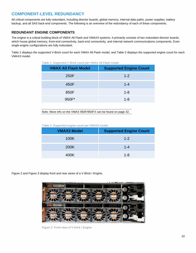
REDUNDANT ENGINE COMPONENTS
The engine is a critical building block of VMAX All Flash and VMAX3 systems. It primarily consists of two redundant director boards,
which house global memory, front-end connectivity, back-end connectivity, and internal network communications components. Even
single-engine configurations are fully redundant.
Table 1 displays the supported V-Brick count for each VMAX All Flash model, and Table 2 displays the supported engine count for each
VMAX3 model.
Table 1: Supported V-Brick count per VMAX All Flash model
VMAX All Flash Model Supported Engine Count
250F 1-2
450F 1-4
850F 1-8
950F* 1-8
Note: More info on the VMAX 950F/950FX can be found on page 32.
Table 2: Supported engine count per VMAX3 model
VMAX3 Model Supported Engine Count
100K 1-2
200K 1-4
400K 1-8
Figure 2 and Figure 3 display front and rear views of a V-Brick / Engine.
Figure 2: Front view of V-brick / Engine
11
Figure 3: Rear view of V-Brick / Engine
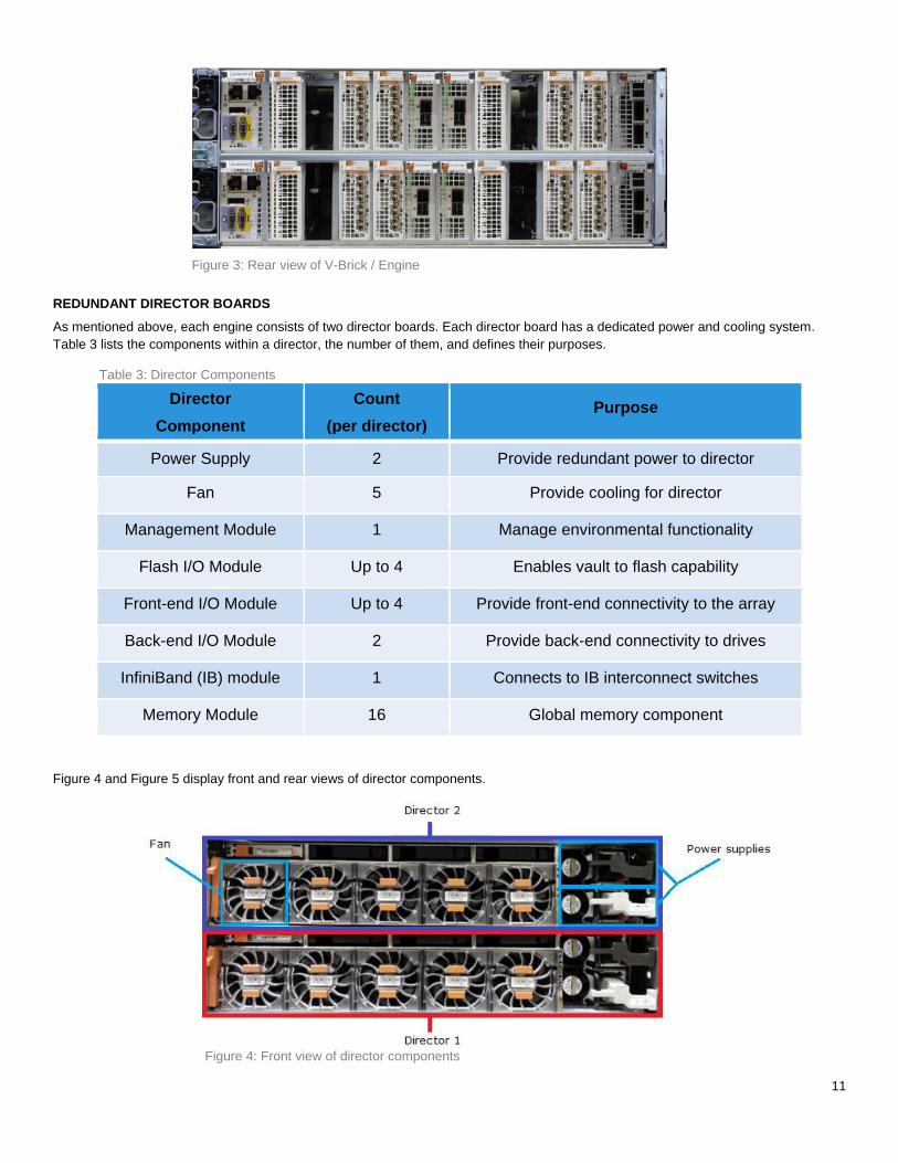
REDUNDANT DIRECTOR BOARDS As mentioned above, each engine consists of two director boards. Each director board has a dedicated power and cooling system.
Table 3 lists the components within a director, the number of them, and defines their purposes.
Table 3: Director Components
Director
Component
Count
(per director) Purpose
Power Supply 2 Provide redundant power to director
Fan 5 Provide cooling for director
Management Module 1 Manage environmental functionality
Flash I/O Module Up to 4 Enables vault to flash capability
Front-end I/O Module Up to 4 Provide front-end connectivity to the array
Back-end I/O Module 2 Provide back-end connectivity to drives
InfiniBand (IB) module 1 Connects to IB interconnect switches
Memory Module 16 Global memory component
Figure 4 and Figure 5 display front and rear views of director components.
Figure 4: Front view of director components
12
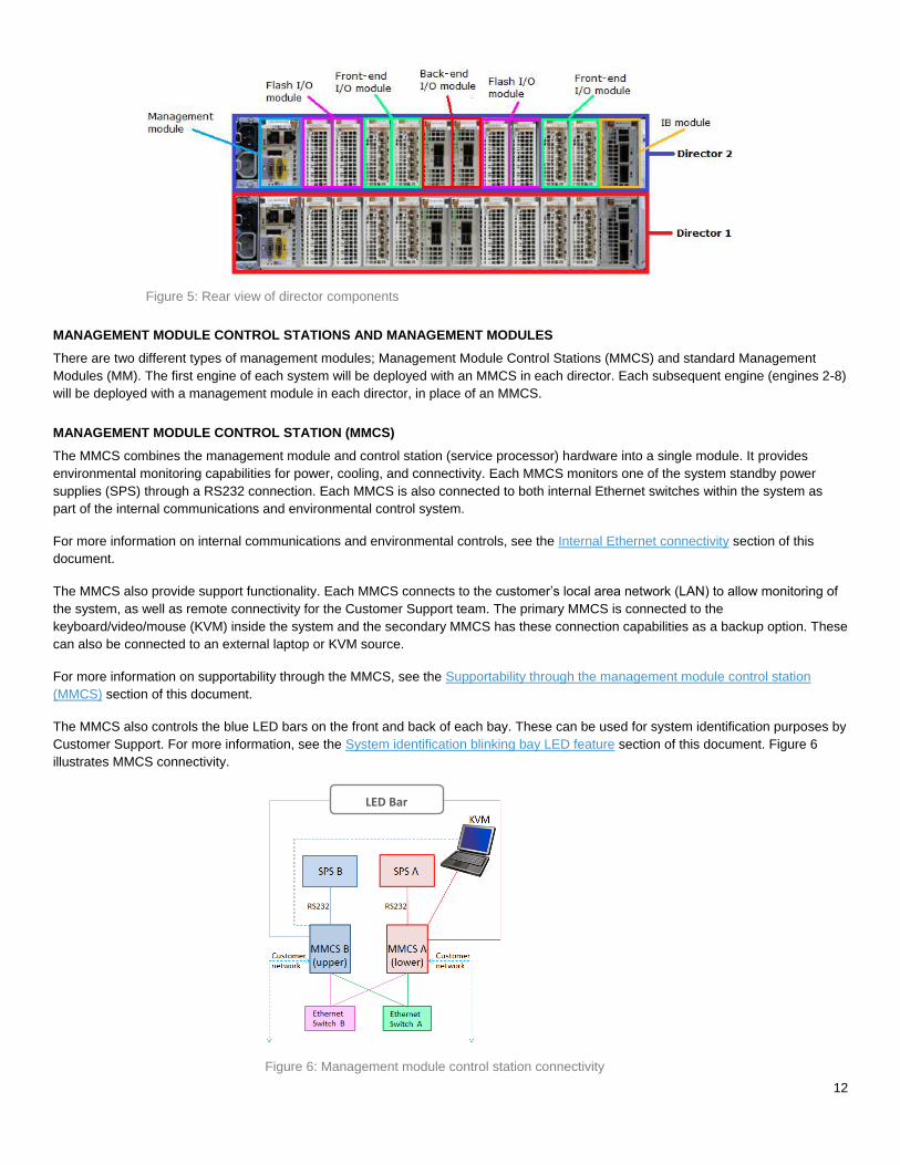
Figure 5: Rear view of director components
MANAGEMENT MODULE CONTROL STATIONS AND MANAGEMENT MODULES
There are two different types of management modules; Management Module Control Stations (MMCS) and standard Management
Modules (MM). The first engine of each system will be deployed with an MMCS in each director. Each subsequent engine (engines 2-8)
will be deployed with a management module in each director, in place of an MMCS.
MANAGEMENT MODULE CONTROL STATION (MMCS)
The MMCS combines the management module and control station (service processor) hardware into a single module. It provides
environmental monitoring capabilities for power, cooling, and connectivity. Each MMCS monitors one of the system standby power
supplies (SPS) through a RS232 connection. Each MMCS is also connected to both internal Ethernet switches within the system as
part of the internal communications and environmental control system.
For more information on internal communications and environmental controls, see the Internal Ethernet connectivity section of this
document.
The MMCS also provide support functionality. Each MMCS connects to the customer’s local area network (LAN) to allow monitoring of
the system, as well as remote connectivity for the Customer Support team. The primary MMCS is connected to the
keyboard/video/mouse (KVM) inside the system and the secondary MMCS has these connection capabilities as a backup option. These
can also be connected to an external laptop or KVM source.
For more information on supportability through the MMCS, see the Supportability through the management module control station
(MMCS) section of this document.
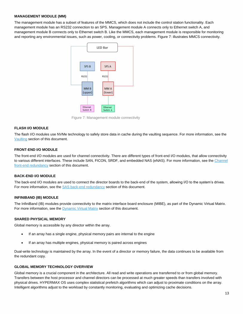
The MMCS also controls the blue LED bars on the front and back of each bay. These can be used for system identification purposes by
Customer Support. For more information, see the System identification blinking bay LED feature section of this document. Figure 6
illustrates MMCS connectivity.
Figure 6: Management module control station connectivity
LED Bar
13
MANAGEMENT MODULE (MM)
The management module has a subset of features of the MMCS, which does not include the control station functionality. Each
management module has an RS232 connection to an SPS. Management module A connects only to Ethernet switch A, and
management module B connects only to Ethernet switch B. Like the MMCS, each management module is responsible for monitoring
and reporting any environmental issues, such as power, cooling, or connectivity problems. Figure 7: illustrates MMCS connectivity.
Figure 7: Management module connectivity
FLASH I/O MODULE
The flash I/O modules use NVMe technology to safely store data in cache during the vaulting sequence. For more information, see the
Vaulting section of this document.
FRONT-END I/O MODULE
The front-end I/O modules are used for channel connectivity. There are different types of front-end I/O modules, that allow connectivity
to various different interfaces. These include SAN, FICON, SRDF, and embedded NAS (eNAS). For more information, see the Channel
front-end redundancy section of this document.
BACK-END I/O MODULE
The back-end I/O modules are used to connect the director boards to the back-end of the system, allowing I/O to the system’s drives.
For more information, see the SAS back-end redundancy section of this document.
INFINIBAND (IB) MODULE
The InfiniBand (IB) modules provide connectivity to the matrix interface board enclosure (MIBE), as part of the Dynamic Virtual Matrix.
For more information, see the Dynamic Virtual Matrix section of this document.
SHARED PHYSICAL MEMORY
Global memory is accessible by any director within the array.
If an array has a single engine, physical memory pairs are internal to the engine
If an array has multiple engines, physical memory is paired across engines
Dual-write technology is maintained by the array. In the event of a director or memory failure, the data continues to be available from
the redundant copy.
GLOBAL MEMORY TECHNOLOGY OVERVIEW
Global memory is a crucial component in the architecture. All read and write operations are transferred to or from global memory.
Transfers between the host processor and channel directors can be processed at much greater speeds than transfers involved with
physical drives. HYPERMAX OS uses complex statistical prefetch algorithms which can adjust to proximate conditions on the array.
Intelligent algorithms adjust to the workload by constantly monitoring, evaluating and optimizing cache decisions.
LED Bar
14
VMAX3 and VMAX All Flash arrays may be configured with up to 2TB of mirrored memory per engine and up to 16TB mirrored per
array.
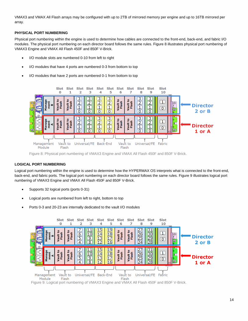
PHYSICAL PORT NUMBERING
Physical port numbering within the engine is used to determine how cables are connected to the front-end, back-end, and fabric I/O
modules. The physical port numbering on each director board follows the same rules. Figure 8 illustrates physical port numbering of
VMAX3 Engine and VMAX All Flash 450F and 850F V-Brick.
I/O module slots are numbered 0-10 from left to right
I/O modules that have 4 ports are numbered 0-3 from bottom to top
I/O modules that have 2 ports are numbered 0-1 from bottom to top
Figure 8: Physical port numbering of VMAX3 Engine and VMAX All Flash 450F and 850F V-Brick.
LOGICAL PORT NUMBERING
Logical port numbering within the engine is used to determine how the HYPERMAX OS interprets what is connected to the front-end,
back-end, and fabric ports. The logical port numbering on each director board follows the same rules. Figure 9 illustrates logical port
numbering of VMAX3 Engine and VMAX All Flash 450F and 850F V-Brick.
Supports 32 logical ports (ports 0-31)
Logical ports are numbered from left to right, bottom to top
Ports 0-3 and 20-23 are internally dedicated to the vault I/O modules
Figure 9: Logical port numbering of VMAX3 Engine and VMAX All Flash 450F and 850F V-Brick.
15
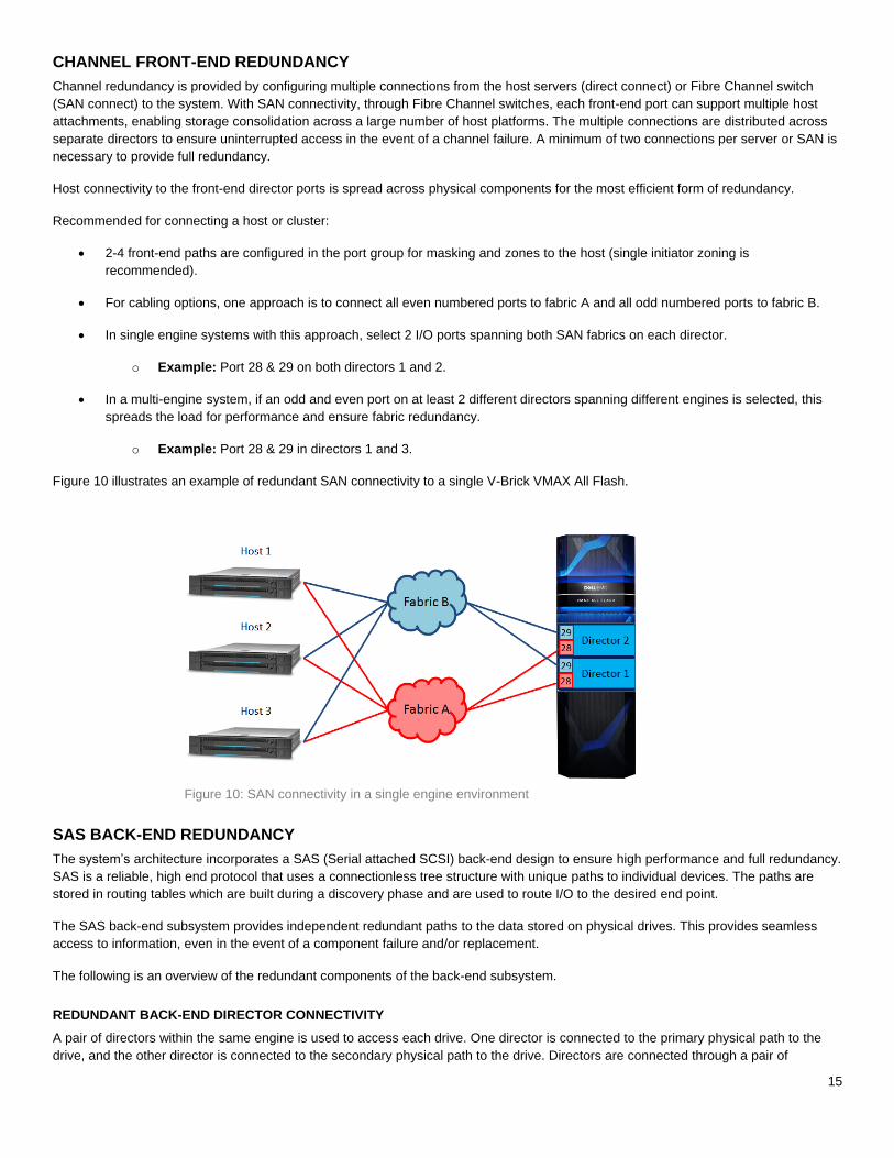
CHANNEL FRONT-END REDUNDANCY
Channel redundancy is provided by configuring multiple connections from the host servers (direct connect) or Fibre Channel switch
(SAN connect) to the system. With SAN connectivity, through Fibre Channel switches, each front-end port can support multiple host
attachments, enabling storage consolidation across a large number of host platforms. The multiple connections are distributed across
separate directors to ensure uninterrupted access in the event of a channel failure. A minimum of two connections per server or SAN is
necessary to provide full redundancy.
Host connectivity to the front-end director ports is spread across physical components for the most efficient form of redundancy.
Recommended for connecting a host or cluster:
2-4 front-end paths are configured in the port group for masking and zones to the host (single initiator zoning is
recommended).
For cabling options, one approach is to connect all even numbered ports to fabric A and all odd numbered ports to fabric B.
In single engine systems with this approach, select 2 I/O ports spanning both SAN fabrics on each director.
o Example: Port 28 & 29 on both directors 1 and 2.
In a multi-engine system, if an odd and even port on at least 2 different directors spanning different engines is selected, this
spreads the load for performance and ensure fabric redundancy.
o Example: Port 28 & 29 in directors 1 and 3.
Figure 10 illustrates an example of redundant SAN connectivity to a single V-Brick VMAX All Flash.
Figure 10: SAN connectivity in a single engine environment
SAS BACK-END REDUNDANCY
The system’s architecture incorporates a SAS (Serial attached SCSI) back-end design to ensure high performance and full redundancy.
SAS is a reliable, high end protocol that uses a connectionless tree structure with unique paths to individual devices. The paths are
stored in routing tables which are built during a discovery phase and are used to route I/O to the desired end point.
The SAS back-end subsystem provides independent redundant paths to the data stored on physical drives. This provides seamless
access to information, even in the event of a component failure and/or replacement.
The following is an overview of the redundant components of the back-end subsystem.
REDUNDANT BACK-END DIRECTOR CONNECTIVITY
A pair of directors within the same engine is used to access each drive. One director is connected to the primary physical path to the
drive, and the other director is connected to the secondary physical path to the drive. Directors are connected through a pair of
16
independent back-end I/O modules and cabling that allow data to be moved back and forth between global memory and the drives.
Each director is connected to global memory through primary and secondary paths, to eliminate possible single points of failure. For
more information on single points of failure, see the Dual-initiator feature section of this document.
REDUNDANT CABLE PATHS
Each back-end I/O module is connected to its associated link control card (LCC) and drive array enclosure (DAE) chain through a
completely independent cable assembly. Each connection carries four paths, providing an increase in reliability and throughput.
REDUNDANT DRIVE PATHS
Each SAS drive has two ports which are connected via a fully independent path. Each of these ports is connected through separate
directors, cables, and LCCs.
POINT-TO-POINT BACK-END
VMAX All Flash and VMAX3 systems use a SAS connectionless, point-to-point network that has an independent relationship with each
drive. This relationship between the back-end controller and each drive allows HYPERMAX OS to analyze drive health and improve
serviceability.
The SAS connectionless, point-to-point network consists of SAS controllers in the back-end I/O modules and SAS expanders in the
LCCs (VMAX DAE60 ICM/LCC and VMAX DAE120 LCC). These controlling points of the SAS network contain routing tables
necessary to move data from point-A to point-B within the network. The routing tables are built in the discovery phase as the SAS
network initializes or in an event of a topology change. For example, a topology change can consist of pull/plug of a drive, or
connect/disconnect of a cable, or pull/plug of an LCC.
DRIVE ARRAY ENCLOSURE (DAE)
Two different types of drive array enclosures (DAE) are available. The VMAX DAE60 accommodates 3.5” drives and 2.5” drives in a
3.5” carrier. The VMAX DAE120 accommodates 2.5” drives. Both types can be mixed together in a single system. The DAE houses the
physical drives as well as the LCCs.
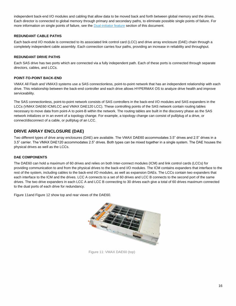
DAE COMPONENTS
The DAE60 can hold a maximum of 60 drives and relies on both Inter-connect modules (ICM) and link control cards (LCCs) for
providing communication to and from the physical drives to the back-end I/O modules. The ICM contains expanders that interface to the
rest of the system, including cables to the back-end I/O modules, as well as expansion DAEs. The LCCs contain two expanders that
each interface to the ICM and the drives. LCC A connects to a set of 60 drives and LCC B connects to the second port of the same
drives. The two drive expanders in each LCC A and LCC B connecting to 30 drives each give a total of 60 drives maximum connected
to the dual ports of each drive for redundancy.
Figure 11and Figure 12 show top and rear views of the DAE60.
Figure 11: VMAX DAE60 (top)
17
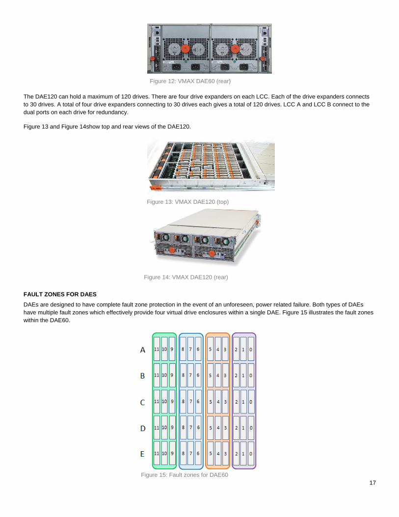
Figure 12: VMAX DAE60 (rear)
The DAE120 can hold a maximum of 120 drives. There are four drive expanders on each LCC. Each of the drive expanders connects
to 30 drives. A total of four drive expanders connecting to 30 drives each gives a total of 120 drives. LCC A and LCC B connect to the
dual ports on each drive for redundancy.
Figure 13 and Figure 14show top and rear views of the DAE120.
Figure 13: VMAX DAE120 (top)
Figure 14: VMAX DAE120 (rear)
FAULT ZONES FOR DAES
DAEs are designed to have complete fault zone protection in the event of an unforeseen, power related failure. Both types of DAEs
have multiple fault zones which effectively provide four virtual drive enclosures within a single DAE. Figure 15 illustrates the fault zones
within the DAE60.
Figure 15: Fault zones for DAE60
18
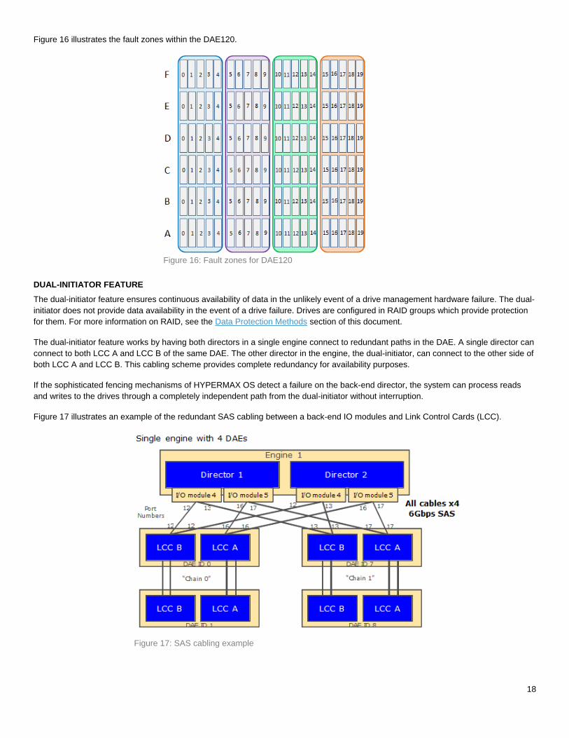
Figure 16 illustrates the fault zones within the DAE120.
Figure 16: Fault zones for DAE120
DUAL-INITIATOR FEATURE
The dual-initiator feature ensures continuous availability of data in the unlikely event of a drive management hardware failure. The dual-
initiator does not provide data availability in the event of a drive failure. Drives are configured in RAID groups which provide protection
for them. For more information on RAID, see the Data Protection Methods section of this document.
The dual-initiator feature works by having both directors in a single engine connect to redundant paths in the DAE. A single director can
connect to both LCC A and LCC B of the same DAE. The other director in the engine, the dual-initiator, can connect to the other side of
both LCC A and LCC B. This cabling scheme provides complete redundancy for availability purposes.
If the sophisticated fencing mechanisms of HYPERMAX OS detect a failure on the back-end director, the system can process reads
and writes to the drives through a completely independent path from the dual-initiator without interruption.
Figure 17 illustrates an example of the redundant SAS cabling between a back-end IO modules and Link Control Cards (LCC).
Figure 17: SAS cabling example
19
DYNAMIC VIRTUAL MATRIX
The dynamic virtual matrix uses Infiniband (56 Gbps) technology to carry control, metadata, and user data through the system. This
technology connects all of the engines in the system to provide a powerful form of redundancy and performance. This allows the
engines to share resources and act as a single entity while communicating. In any system that has two or more engines, there are two
redundant matrix interface board enclosures (MIBE) that connect to the fabric I/O modules of each director board. The purpose of the
dynamic virtual matrix is to create a communication interconnection between all of the engines, and therefore a single engine system
does not require a dynamic virtual matrix or MIBEs.
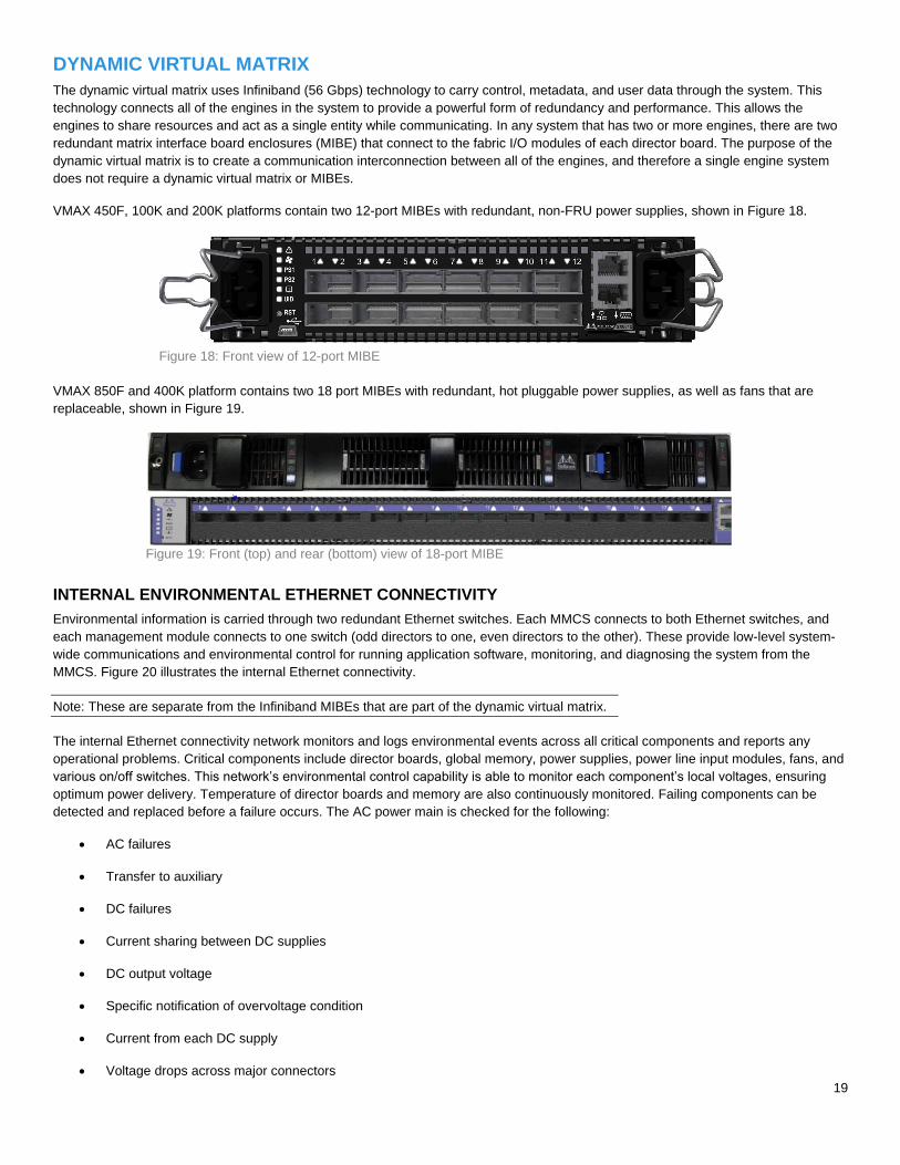
VMAX 450F, 100K and 200K platforms contain two 12-port MIBEs with redundant, non-FRU power supplies, shown in Figure 18.
Figure 18: Front view of 12-port MIBE
VMAX 850F and 400K platform contains two 18 port MIBEs with redundant, hot pluggable power supplies, as well as fans that are
replaceable, shown in Figure 19.
Figure 19: Front (top) and rear (bottom) view of 18-port MIBE
INTERNAL ENVIRONMENTAL ETHERNET CONNECTIVITY
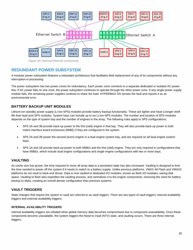
Environmental information is carried through two redundant Ethernet switches. Each MMCS connects to both Ethernet switches, and
each management module connects to one switch (odd directors to one, even directors to the other). These provide low-level system-
wide communications and environmental control for running application software, monitoring, and diagnosing the system from the
MMCS. Figure 20 illustrates the internal Ethernet connectivity.
Note: These are separate from the Infiniband MIBEs that are part of the dynamic virtual matrix.
The internal Ethernet connectivity network monitors and logs environmental events across all critical components and reports any
operational problems. Critical components include director boards, global memory, power supplies, power line input modules, fans, and
various on/off switches. This network’s environmental control capability is able to monitor each component’s local voltages, ensuring
optimum power delivery. Temperature of director boards and memory are also continuously monitored. Failing components can be
detected and replaced before a failure occurs. The AC power main is checked for the following:
AC failures
Transfer to auxiliary
DC failures
Current sharing between DC supplies
DC output voltage
Specific notification of overvoltage condition
Current from each DC supply
Voltage drops across major connectors
20
Figure 20: Internal Ethernet connectivity
REDUNDANT POWER SUBSYSTEM
A modular power subsystem features a redundant architecture that facilitates field replacement of any of its components without any
interruption in processing.
The power subsystem has two power zones for redundancy. Each power zone connects to a separate dedicated or isolated AC power
line. If AC power fails on one zone, the power subsystem continues to operate through the other power zone. If any single power supply
module fails, the remaining power supplies continue to share the load. HYPERMAX OS senses the fault and reports it as an
environmental error.
BATTERY BACKUP UNIT MODULES
Lithium-ion standby power supply (Li-Ion-SPS) modules provide battery backup functionality. These are lighter and have a longer shelf
life than lead acid SPS modules. System bays can include up to six Li-Ion-SPS modules. The number and location of SPS modules
depends on the type of system bay and the number of engines in the array. The following rules apply to SPS configurations:
SPS 3A and 3B provide back-up power to the first (odd) engine in that bay. They will also provide back-up power to both
matrix interface board enclosures (MIBE) if they are configured in the system.
SPS 2A and 2B power the second (even) engine in a dual engine system bay, and are required on all dual engine system
bays.
SPS 1A and 1B provide back-up power to both MIBEs and the first (odd) engine. They are only required in configurations that
have MIBEs, which include dual engine configurations and single engine configurations with two or more bays.
VAULTING
As cache size has grown, the time required to move all array data to a persistent state has also increased. Vaulting is designed to limit
the time needed to power off the system if it needs to switch to a battery supply. Unlike previous platforms, VMAX All Flash and VMAX3
platforms do not vault to back-end drives. Data is now vaulted to dedicated I/O modules, known as flash I/O modules, saving disk
space. Vaulting to flash also expedites the vaulting process, and centralizes it to the engine components, removing the need for battery
backup to disks, creating an overall denser configuration than previous systems.
VAULT TRIGGERS
State changes that require the system to vault are referred to as vault triggers. There are two types of vault triggers: internal availability
triggers and external availability triggers.
INTERNAL AVAILABILITY TRIGGERS
Internal availability triggers are initiated when global memory data becomes compromised due to component unavailability. Once these
components become unavailable, the system triggers the Need to Vault (NTV) state, and vaulting occurs. There are three internal
triggers:
21
1. Vault flash availability – The flash I/O modules are used for storage of meta data under normal conditions, as well as storing
any data that is being saved during the vaulting process. When the overall available flash space in the flash I/O modules
becomes the same size as N copy of global memory, the NTV process triggers. This is to ensure that all of the data is saved
before a potential further loss of vault flash space occurs.
2. Global memory (GM) availability – When any of the mirrored director pairs are both unhealthy either logically or
environmentally, NTV triggers because of GM unavailability.
3. Fabric availability – When both the fabric switches are environmentally unhealthy, NTV triggers because of fabric
unavailability.
EXTERNAL AVAILABILITY TRIGGERS
External availability triggers are initiated under circumstances when global memory data is not compromised, but it is determined that
the system preservation is improved by vaulting. Vaulting in this context is used as a mechanism to stop host activity, facilitate easy
recovery or act as an attempt to proactively take action to prevent potential data loss. There are two external triggers:
1. Engine trigger – When an entire engine fails, the system vaults.
2. DAE trigger – If the system has lost access to the whole DAE or DAEs, including dual-initiator failure, and loss of access
causes configured RAID members to become non-accessible, the system vaults.
POWER-DOWN OPERATION
When a system is powered down or transitioned to offline, or when environmental conditions trigger a vault situation, a vaulting
procedure occurs. During power-down or power loss, the part of global memory that is saved first reaches a consistent image (no more
writes). The directors then write the appropriate sections of global memory to the flash I/O modules, saving three copies of the logical
data. The battery backup unit (BBU) modules maintain power to the system during the power-down process for up to 5 minutes.
POWER-UP OPERATION
During power-up, the data is written back to global memory to restore the system. When the system is powered on the startup program
does the following:
Initializes the hardware and the environmental system
Restores the global memory from the saved data while checking the integrity of the data. This is accomplished by taking
sections from each copy of global memory that was saved during the power-down operation and combining them into a single
complete copy of global memory. If there are any data integrity issues in a section of the first copy that was saved, then that
section is extracted from the second copy during this process.
Performs a cleanup, data structure integrity, and reinitialization of needed global memory data structures
At the end of the startup program, the system resumes normal operation when the BBUs are recharged enough to support another
vault. If any condition is not safe, the system does not resume operation and calls Customer Support for diagnosis and repair. In this
state, Customer Support can communicate with the system and find out the reason for not resuming normal operation.
DATA PROTECTION METHODS Although the system has standard features that provide a higher level of data availability than conventional DASDs, the following data
protection options ensure an even greater level of data recoverability and availability:
RAID 1 (Mirroring)
RAID 5
RAID 6
Local RAID
Thin provisioning
22
Drive sparing
Local replication with TimeFinder
Remote replication with Symmetrix Remote Data Facility (SRDF)
Data At Rest Encryption (D@RE)
These data protection options (excluding disk sparing) are configurable on individual physical volumes, so that different levels of
protection can be applied to different datasets within the same system.
RAID 1 (MIRRORING)
RAID 1 configurations have higher performance in most applications because each drive has a copy of the data. Accordingly, it is
possible for the system to be satisfying two I/O requests simultaneously by sending or receiving one from either copy. Mirrored volumes
also have lower response times due to the Dynamic Mirror Service Policy (DMSP), which automatically determines the optimal disk to
read to achieve maximum performance. Mirrored volumes also have lower response times since the system can access the data on
either of the mirrored drives.
Mirrored configurations also provide higher performance if there is a disk failure since another complete copy of the data is immediately
available. Furthermore, since only two disks are used for the mirror, the chance of failure on multiple drives containing the same data is
reduced.
RAID 5
This is an implementation of the industry-standard RAID 5 data protection technique with rotating parity across all members of the RAID
5 set. In the event of a physical drive failure, the missing data is rebuilt by reading the remaining drives in the RAID group and
performing XOR calculations.
RAID 5 provides cost-effective data protection against drive failures. While the most demanding environments continue to opt for
mirrored storage for maximum performance, RAID 5 configurations offer an extremely attractive alternative for information storage
where price is more important than performance.
RAID 5 is available in two configurations:
RAID 5 (3+1) – Data and parity are striped across 4 drives (3 data, 1 parity)
RAID 5 (7+1) – Data and parity are striped across 8 drives (7 data, 1 parity)
RAID 6
Protection schemes such as RAID 1 and RAID 5 can protect a system from a single physical drive failure within a mirrored pair or RAID
group. RAID 6 supports the ability to rebuild data in the event that two drives fail within a RAID group.
Dell EMC’s implementation of RAID 6 calculates two types of parity. This is important during events when two drives within the same
RAID group fail, as it still allows the data in this scenario to be reconstructed. Horizontal parity is identical to RAID 5 parity, which is
calculated from the data across all of the disks in the RAID group. Diagonal parity is calculated on a diagonal subset of data members.
For applications without demanding performance needs, RAID 6 provides the highest data availability.
LOCAL RAID
Local RAID is a new concept that puts all members of a RAID group behind a single engine. This improves back-end performance and
drive rebuild time, while still supporting the dual-initiator failover/failback model. Local RAID is implemented in all VMAX All Flash and
VMAX3 environments.
The following member distribution rules apply to Local RAID configurations:
No two members of the same RAID group can be placed on the same disk
Disks reside in disk groups
23
Each disk group supports only one RAID type
One disk group per disk type is created by default
Each disk group is provisioned with its own spare disks
Aside from improved performance, there are other benefits associated with Local RAID, including the following:
Elimination of cross-bay cabling for direct/daisy chain DAE cabling
Dispersion at the engine/bay level
Configuration of new systems or upgrades with any combination of contiguous or dispersed engines/bays
Can position engine/bay on either side of system bay #1
Most flexible floor planning capability in the industry
THIN PROVISIONING
Thin Provisioning enables the ability to increase capacity utilization by enabling more storage to be presented to a host than is
physically consumed, and by allocating storage only as needed from a shared virtual pool. Thin Provisioning also simplifies storage
management by making data layout easier through automated wide striping, and by reducing the steps required to accommodate
growth.
Thin Provisioning uses a type of host-accessible device called a virtually provisioned device, also known as a thin device, which does
not need to have physical storage completely allocated at the time the devices are created and presented to a host. The physical
storage that is used to supply drive space for a virtually provisioned device comes from a shared storage pool, also known as a storage
resource pool (SRP). The SRP is comprised of one or more data pools containing internal devices called data devices. These data
devices are dedicated to the purpose of providing the actual physical storage used by virtually provisioned devices.
When a write is performed to a portion of the virtually provisioned device, the array allocates a minimum allotment of physical storage
from the pool and maps that storage to a region of the virtually provisioned device, including the area targeted by the write.
The storage allocation operations are performed in small units of storage called virtually provisioned device extents. Extents may also
be called chunks. The virtually provisioned device extent size is 1 track (128 KB).
When a read is performed on a virtually provisioned device, the data being read is retrieved from the appropriate data device in the
SRP to which the virtually provisioned device is bound. Reads directed to an area of a virtually provisioned device that has not been
mapped do not trigger allocation operations. Reading an unmapped block returns null data. When more storage is required to service
existing or future virtually provisioned devices, data devices can be added to existing virtually provisioned data pools within the SRP.
For more information on Thin Provisioning on VMAX3, refer to Dell EMC® VMAX3 Service Level Provisioning with Fully Automated
Storage Tiering™ (FAST) Technical Notes.
DRIVE SPARING
HYPERMAX OS supports Direct Sparing to automatically replace a failing drive with a spare drive. Direct Sparing is supported with all
protection types, including RAID 6 (14+2).
Two traditional sparing factors, vault drives and specific back-end director within the engine, do not apply to VMAX All Flash and
VMAX3 systems. These systems vault to flash I/O modules on the engine rather than vault drives, and HYPERMAX OS can
dynamically relocate spare drives across back-end directors within the same engine.
The major factor with Direct Sparing is the power zone within the disk enclosure where the spare drive, failing drive, and other RAID
members are located. RAID 1 and RAID 5 are only allowed to have one member per power zone, and RAID 6 is allowed to have up to
two members per power zone.
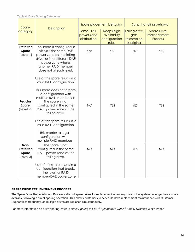
HYPERMAX OS uses the same categories for spare drives: Preferred, Regular, and Non-Preferred. The disk sparing script selects the
best available drive by using the rules in Table 4.
24
Table 4: Drive Sparing Categories
Spare
category
Description
Spare placement behavior
Script handling behavior
Same DAE
power zone
distribution
Keeps high
availability
configuration
rules
Failing drive
gets
restored to
its original
positions
Spare Drive
Replenishment
Process
Preferred
Spare
(Level 1)
The spare is configured in
e i ther the same DAE
power zone as the failing
drive, or in a different DAE
power zone where
another RAID member
does not already exist.
Use of this spare results in a
valid RAID configuration.
This spare does not create
a configuration with
multiple RAID members in
the same DAE power
zone.
Yes
YES
NO
YES
Regular
Spare
(Level 2)
The spare is not
configured in the same
D A E power zone as the
failing drive.
Use of this spare results in a
valid RAID configuration.
This creates a legal
configuration with
multiple RAID members
in the same DAE power
zone.
NO
YES
YES
YES
Non-
Preferred
Spare
(Level 3)
The spare is not
configured in the same
D A E power zone as the
failing drive.
Use of this spare results in a
configuration that breaks
the rules for RAID
member/DAE power zone
distribution.
NO
NO
YES
NO
SPARE DRIVE REPLENISHMENT PROCESS
The Spare Drive Replenishment Process calls out spare drives for replacement when any drive in the system no longer has a spare
available following a direct sparing operation. This allows customers to schedule drive replacement maintenance with Customer
Support less frequently, as multiple drives are replaced simultaneously.
For more information on drive sparing, refer to Drive Sparing in EMC® Symmetrix® VMAX® Family Systems White Paper.
25
LOCAL REPLICATION USING TIMEFINDER
TimeFinder® software delivers point-in-time copies of volumes that can be used for backups, decision support, data warehouse
refreshes, or any other process that requires parallel access to production data.
Previous VMAX families offer several different TimeFinder offerings, each with their own characteristics and ideal use cases. These
offerings also have several similarities, the main one being that they each require a target volume to retain snapshot or clone data.
TimeFinder in HYPERMAX OS 5977 introduces TimeFinder SnapVX which combines the best aspects of the previous TimeFinder
offerings, adds some new ease-of-use features, and increases scalability.
SnapVX provides very low impact snapshots and clones for data volumes. SnapVX supports up to 256 snapshots per source volume,
which are tracked as versions with less overhead and simple relationship tracking. Users can assign names to identify their snapshots,
and they have the option of setting automatic expiration dates on each snapshot.
SnapVX provides the ability to manage consistent point-in-time copies for storage groups with a single operation. Up to 1024 target
volumes can be linked per source volume, providing read/write access as pointers or full copies.
TimeFinder in HYPERMAX OS also provides compatibility modes for users who rely on their TimeFinder Mirror, Snap, Clone, or VP
Snap command scripts. This will allow users to use their existing scripts while learning how to take advantage of the new features of
SnapVX.
For more information on TimeFinder SnapVX, refer to Dell EMC®HYPERMAX OS TimeFinder Local Replication Technical Notes.
REMOTE REPLICATION USING SRDF
Symmetrix Remote Data Facility (SRDF) solutions provide industry-leading disaster recovery and data mobility solutions. SRDF
replicates data between 2, 3 or 4 arrays located in the same room, on the same campus, or thousands of kilometers apart.
SRDF synchronous (SRDF/S) maintains a real-time copy at arrays located within 200 kilometers. Writes from the production
host are acknowledged from the local array when they are written to cache at the remote array.
SRDF asynchronous (SRDF/A) maintains a dependent-write consistent copy at arrays located at unlimited distances. Writes
from the production host are acknowledge immediately by the local array, thus replication has no impact on host performance.
Data at the remote array is typically only seconds behind the primary site.
SRDF disaster recovery solutions use “active, remote” mirroring and dependent-write logic to create consistent copies of data.
Dependent-write consistency ensures transactional consistency when the applications are restarted at the remote location. You can
tailor SRDF to meet various Recovery Point Objectives/Recovery Time Objectives.
Using only SRDF, you can create complete solutions to:
Create real-time (SRDF/S) or dependent-write-consistent (SRDF/A) copies at 1, 2, or 3 remote arrays.
Move data quickly over extended distances.
Provide 3-site disaster recovery with zero data loss recovery, business continuity protection and disaster-restart.
You can integrate SRDF with other Dell EMC products to create complete solutions to:
Restart operations after a disaster with zero data loss and business continuity protection.
Restart operations in cluster environments. For example Microsoft Cluster Server with Microsoft Failover Clusters.
Monitor and automate restart operations on an alternate local or remote server.
Automate restart operations in VMware environments.
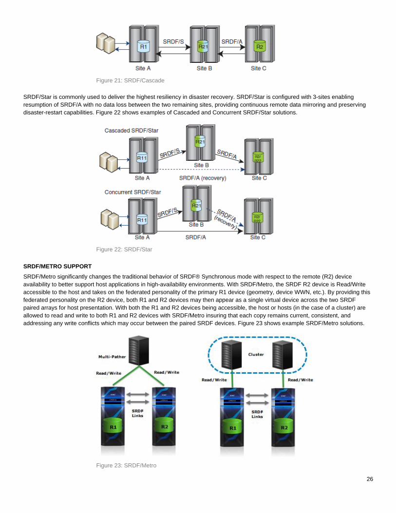
SRDF/CASCADE AND SRDF/STAR SUPPORT
SRDF/Cascade configurations use 3-site remote replication with SRDF/A mirroring between sites B and C, delivering additional disaster
restart flexibility. Figure 21 shows an example of an SRDF/Cascade solution.
26
Figure 21: SRDF/Cascade
SRDF/Star is commonly used to deliver the highest resiliency in disaster recovery. SRDF/Star is configured with 3-sites enabling
resumption of SRDF/A with no data loss between the two remaining sites, providing continuous remote data mirroring and preserving
disaster-restart capabilities. Figure 22 shows examples of Cascaded and Concurrent SRDF/Star solutions.
Figure 22: SRDF/Star
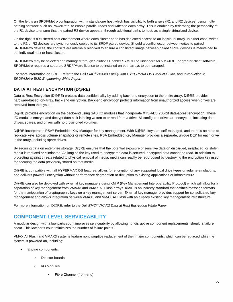
SRDF/METRO SUPPORT
SRDF/Metro significantly changes the traditional behavior of SRDF® Synchronous mode with respect to the remote (R2) device
availability to better support host applications in high-availability environments. With SRDF/Metro, the SRDF R2 device is Read/Write
accessible to the host and takes on the federated personality of the primary R1 device (geometry, device WWN, etc.). By providing this
federated personality on the R2 device, both R1 and R2 devices may then appear as a single virtual device across the two SRDF
paired arrays for host presentation. With both the R1 and R2 devices being accessible, the host or hosts (in the case of a cluster) are
allowed to read and write to both R1 and R2 devices with SRDF/Metro insuring that each copy remains current, consistent, and
addressing any write conflicts which may occur between the paired SRDF devices. Figure 23 shows example SRDF/Metro solutions.
Figure 23: SRDF/Metro
27
On the left is an SRDF/Metro configuration with a standalone host which has visibility to both arrays (R1 and R2 devices) using multi-
pathing software such as PowerPath, to enable parallel reads and writes to each array. This is enabled by federating the personality of
the R1 device to ensure that the paired R2 device appears, through additional paths to host, as a single virtualized device.
On the right is a clustered host environment where each cluster node has dedicated access to an individual array. In either case, writes
to the R1 or R2 devices are synchronously copied to its SRDF paired device. Should a conflict occur between writes to paired
SRDF/Metro devices, the conflicts are internally resolved to ensure a consistent image between paired SRDF devices is maintained to
the individual host or host cluster.
SRDF/Metro may be selected and managed through Solutions Enabler SYMCLI or Unisphere for VMAX 8.1 or greater client software.
SRDF/Metro requires a separate SRDF/Metro license to be installed on both arrays to be managed.
For more information on SRDF, refer to the Dell EMC®VMAX3 Family with HYPERMAX OS Product Guide, and Introduction to
SRDF/Metro EMC Engineering White Paper.
DATA AT REST ENCRYPTION (D@RE)
Data at Rest Encryption (D@RE) protects data confidentiality by adding back-end encryption to the entire array. D@RE provides
hardware-based, on-array, back-end encryption. Back-end encryption protects information from unauthorized access when drives are
removed from the system.
D@RE provides encryption on the back-end using SAS I/O modules that incorporate XTS-AES 256-bit data-at-rest encryption. These
I/O modules encrypt and decrypt data as it is being written to or read from a drive. All configured drives are encrypted, including data
drives, spares, and drives with no provisioned volumes.
D@RE incorporates RSA® Embedded Key Manager for key management. With D@RE, keys are self-managed, and there is no need to
replicate keys across volume snapshots or remote sites. RSA Embedded Key Manager provides a separate, unique DEK for each drive
in the array, including spare drives.
By securing data on enterprise storage, D@RE ensures that the potential exposure of sensitive data on discarded, misplaced, or stolen
media is reduced or eliminated. As long as the key used to encrypt the data is secured, encrypted data cannot be read. In addition to
protecting against threats related to physical removal of media, media can readily be repurposed by destroying the encryption key used
for securing the data previously stored on that media.
D@RE is compatible with all HYPERMAX OS features, allows for encryption of any supported local drive types or volume emulations,
and delivers powerful encryption without performance degradation or disruption to existing applications or infrastructure.
D@RE can also be deployed with external key managers using KMIP (Key Management Interoperability Protocol) which will allow for a
separation of key management from VMAX3 and VMAX All Flash arrays. KMIP is an industry standard that defines message formats
for the manipulation of cryptographic keys on a key management server. External key manager provides support for consolidated key
management and allows integration between VMAX3 and VMAX All Flash with an already existing key management infrastructure.
For more information on D@RE, refer to the Dell EMC® VMAX3 Data at Rest Encryption White Paper.
COMPONENT-LEVEL SERVICEABILITY
A modular design with a low parts count improves serviceability by allowing nondisruptive component replacements, should a failure
occur. This low parts count minimizes the number of failure points.
VMAX All Flash and VMAX3 systems feature nondisruptive replacement of their major components, which can be replaced while the
system is powered on, including:
Engine components:
o Director boards
o I/O Modules
Fibre Channel (front-end)
28
Embedded NAS (eNAS)
SAS (back-end)
Flash (Vault)
SRDF Compression
Inline Compression
o Management modules/management module control stations
o InfiniBand (IB) module
o Power supplies
o Fans
Disk Array Enclosure (DAE) components:
o Link Control Cards (LCC)
o Power supplies
o SAS & flash drives
o Fans
o System Status Card (SSC)
Cabinet Components
o Matrix interface board enclosures (MIBE)
o Fans
o Power supplies
o Ethernet switches
o Standby Power Supplies (SPS) - Lithium Ion batteries
o Power Distribution Units (PDU)
VMAX All Flash and VMAX3 systems provide full component-level redundancy to protect against a component failure and ensure
continuous and uninterrupted access to information. This nondisruptive replacement capability allows the Customer Support Engineer
to install a new component, initialize it if necessary, and bring it online without:
Disrupting access to unaffected volumes
Powering down the unit
Stopping the operating system
Taking unaffected channel paths offline
Taking devices offline (other than the affected device)
FLASHING RACK LIGHTS
Each VMAX All Flash and VMAX3 bay has an LED bar on the front and rear that perform a valuable function during service
activities. Procedures such as installation, component replacement, and cable connectivity verification send a signal to the appropriate
29
LED bar(s) initiating a blinking of the LED, helping to guide service personnel to the correct bay. Additional indicator LEDs inside the
bay, along with detailed instructions provided by the service procedure on the MMCS, further guide service personnel to the correct
component(s). This is a very valuable feature in today’s data centers, especially on dispersed bay systems.
The state of the LED bar on a bay can also be changed by way of the Solutions Enabler command symcfg set –led and through
Unisphere for VMAX under the System Hardware menu.
Each light bar is connected to both power zones for redundant power. The light bars themselves as well as their cabling can be
replaced nondisruptively.
Note: VMAX 250F bays do not have LED bars
NONDISRUPTIVE HYPERMAX OS UPGRADES
Interim updates of the HYPERMAX Operating System can be performed remotely by the Remote Change Management (RCM) group.
These updates provide enhancements to performance algorithms, error recovery and reporting techniques, diagnostics, and
HYPERMAX OS fixes. They also provide new features and functionality for HYPERMAX OS. During an online HYPERMAX OS code
load, a member of the RCM team downloads the new HYPERMAX OS code to the MMCS. The new HYPERMAX OS code loads into
the EEPROM areas within the directors, and remains idle until requested for a hot load in the control store as described in the next
paragraph.
The system does not require customer action during the performance of this function. All directors remain online to the host processor,
thus maintaining application access. The system loads executable HYPERMAX OS code within each director hardware resource until
all directors are loaded. Once the executable HYPERMAX OS code is loaded, internal processing is synchronized and the new code
becomes operational.
VMAX 250F
The Q3 2016 Service Release of HYPERMAX OS introduced support for the VMAX 250F. The F package includes base software titles.
VMAX 250FX ships with the FX package, adding additional software titles to the F bundle.
VMAX 250F scales from 1 to 2 V-Bricks, providing a system total of up to 100 drives, 1PBe capacity, 4TBr cache, and 64 front-end
ports, all within a single floor tile. A single, fully-configured VMAX 250F will only consume the bottom half of the cabinet. The top half of
the cabinet can be used for either a completely separate VMAX 250F or for non-Dell EMC hardware.
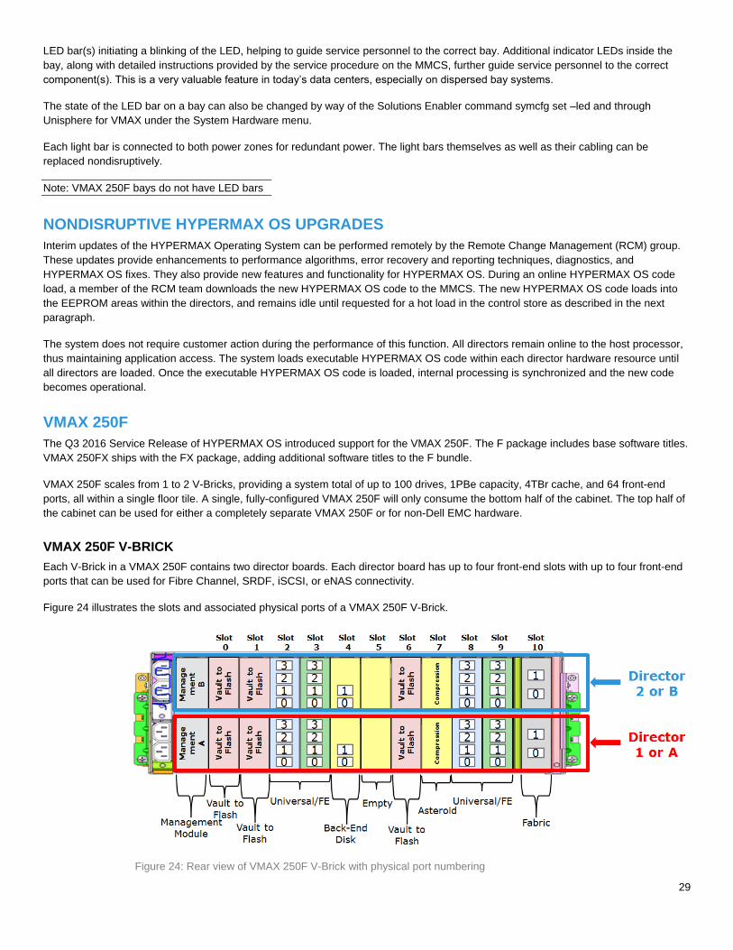
VMAX 250F V-BRICK
Each V-Brick in a VMAX 250F contains two director boards. Each director board has up to four front-end slots with up to four front-end
ports that can be used for Fibre Channel, SRDF, iSCSI, or eNAS connectivity.
Figure 24 illustrates the slots and associated physical ports of a VMAX 250F V-Brick.
Figure 24: Rear view of VMAX 250F V-Brick with physical port numbering
30
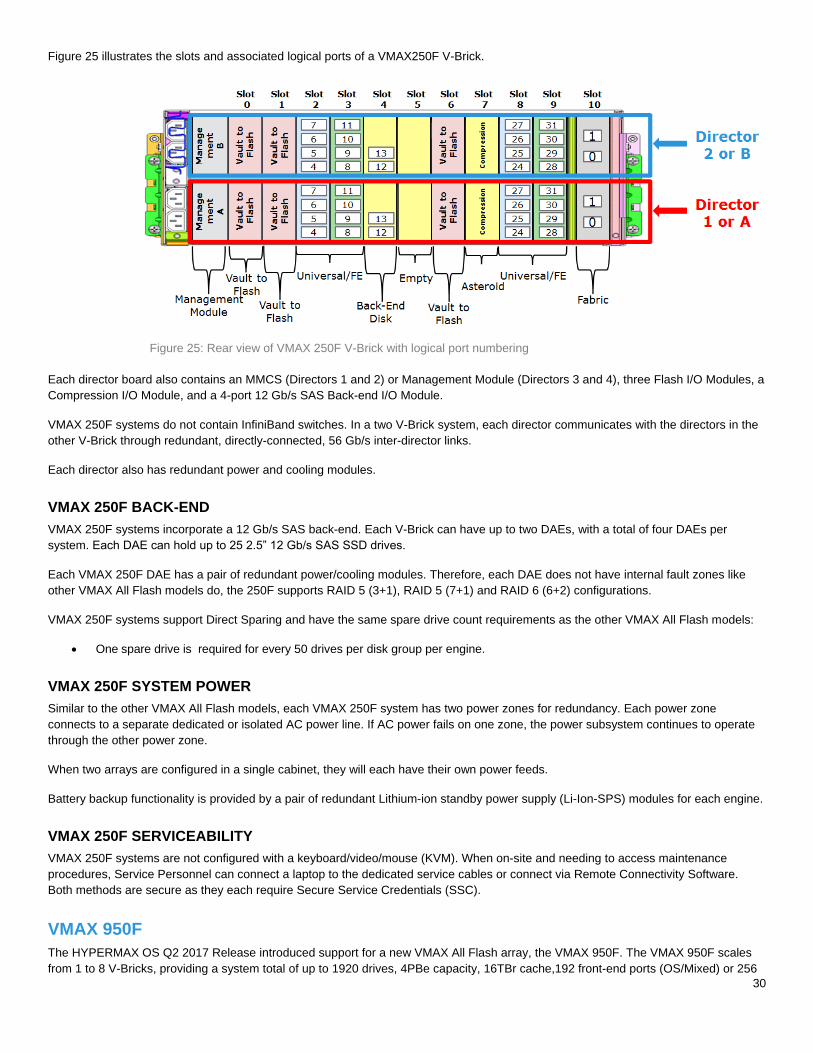
Figure 25 illustrates the slots and associated logical ports of a VMAX250F V-Brick.
Figure 25: Rear view of VMAX 250F V-Brick with logical port numbering
Each director board also contains an MMCS (Directors 1 and 2) or Management Module (Directors 3 and 4), three Flash I/O Modules, a
Compression I/O Module, and a 4-port 12 Gb/s SAS Back-end I/O Module.
VMAX 250F systems do not contain InfiniBand switches. In a two V-Brick system, each director communicates with the directors in the
other V-Brick through redundant, directly-connected, 56 Gb/s inter-director links.
Each director also has redundant power and cooling modules.
VMAX 250F BACK-END
VMAX 250F systems incorporate a 12 Gb/s SAS back-end. Each V-Brick can have up to two DAEs, with a total of four DAEs per
system. Each DAE can hold up to 25 2.5” 12 Gb/s SAS SSD drives.
Each VMAX 250F DAE has a pair of redundant power/cooling modules. Therefore, each DAE does not have internal fault zones like
other VMAX All Flash models do, the 250F supports RAID 5 (3+1), RAID 5 (7+1) and RAID 6 (6+2) configurations.
VMAX 250F systems support Direct Sparing and have the same spare drive count requirements as the other VMAX All Flash models:
One spare drive is required for every 50 drives per disk group per engine.
VMAX 250F SYSTEM POWER
Similar to the other VMAX All Flash models, each VMAX 250F system has two power zones for redundancy. Each power zone
connects to a separate dedicated or isolated AC power line. If AC power fails on one zone, the power subsystem continues to operate
through the other power zone.
When two arrays are configured in a single cabinet, they will each have their own power feeds.
Battery backup functionality is provided by a pair of redundant Lithium-ion standby power supply (Li-Ion-SPS) modules for each engine.
VMAX 250F SERVICEABILITY
VMAX 250F systems are not configured with a keyboard/video/mouse (KVM). When on-site and needing to access maintenance
procedures, Service Personnel can connect a laptop to the dedicated service cables or connect via Remote Connectivity Software.
Both methods are secure as they each require Secure Service Credentials (SSC).
VMAX 950F
The HYPERMAX OS Q2 2017 Release introduced support for a new VMAX All Flash array, the VMAX 950F. The VMAX 950F scales
from 1 to 8 V-Bricks, providing a system total of up to 1920 drives, 4PBe capacity, 16TBr cache,192 front-end ports (OS/Mixed) or 256
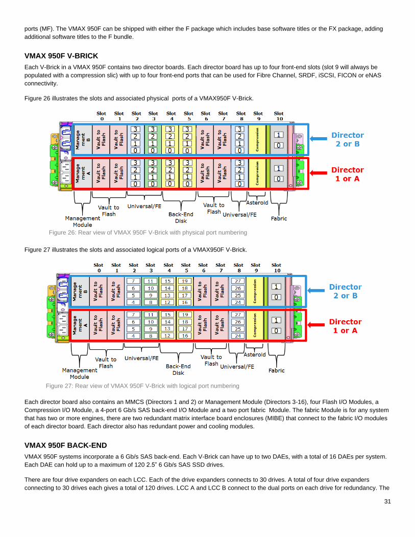
31
ports (MF). The VMAX 950F can be shipped with either the F package which includes base software titles or the FX package, adding
additional software titles to the F bundle.
VMAX 950F V-BRICK
Each V-Brick in a VMAX 950F contains two director boards. Each director board has up to four front-end slots (slot 9 will always be
populated with a compression slic) with up to four front-end ports that can be used for Fibre Channel, SRDF, iSCSI, FICON or eNAS
connectivity.
Figure 26 illustrates the slots and associated physical ports of a VMAX950F V-Brick.
Figure 26: Rear view of VMAX 950F V-Brick with physical port numbering
Figure 27 illustrates the slots and associated logical ports of a VMAX950F V-Brick.
Figure 27: Rear view of VMAX 950F V-Brick with logical port numbering
Each director board also contains an MMCS (Directors 1 and 2) or Management Module (Directors 3-16), four Flash I/O Modules, a
Compression I/O Module, a 4-port 6 Gb/s SAS back-end I/O Module and a two port fabric Module. The fabric Module is for any system
that has two or more engines, there are two redundant matrix interface board enclosures (MIBE) that connect to the fabric I/O modules
of each director board. Each director also has redundant power and cooling modules.
VMAX 950F BACK-END
VMAX 950F systems incorporate a 6 Gb/s SAS back-end. Each V-Brick can have up to two DAEs, with a total of 16 DAEs per system.
Each DAE can hold up to a maximum of 120 2.5” 6 Gb/s SAS SSD drives.
There are four drive expanders on each LCC. Each of the drive expanders connects to 30 drives. A total of four drive expanders
connecting to 30 drives each gives a total of 120 drives. LCC A and LCC B connect to the dual ports on each drive for redundancy. The
32
DAE is designed to have complete fault zone protection in the event of an unforeseen, power related failure. The DAE has multiple fault
zones which effectively provide four virtual drive enclosures within a single DAE.
VMAX 950F systems support Direct Sparing and have the same spare drive count requirements as the other VMAX All Flash models:
One spare drive is required for every 50 drives per disk group per engine.
VMAX 950F SYSTEM POWER
Similar to the other VMAX All Flash models, each VMAX 950F system has two power zones for redundancy. Each power zone
connects to a separate dedicated or isolated AC power line. If AC power fails on one zone, the power subsystem continues to operate
through the other power zone.
Battery backup functionality is provided by a pair of redundant Lithium-ion standby power supply (Li-Ion-SPS) modules for each engine.
VMAX 950F SERVICEABILITY
The 950F systems provide full component-level redundancy to protect against a component failure and ensure continuous and
uninterrupted access to information. This nondisruptive replacement capability allows Dell EMC support personnel to install a new
component, initialize it if necessary, and bring it online without:
Disrupting access to unaffected volumes
Powering down the unit
Stopping the operating system
Taking unaffected channel paths offline
Taking devices offline (other than the affected device)
CONCLUSION
VMAX All Flash and VMAX3 platforms improve upon every aspect of the already extraordinary VMAX product line. This is a system
with highly redundant hardware components, creating a remarkably reliable environment that has also been condensed into a
configuration that minimizes carbon footprint in the data center and increases total cost of ownership. The introduction of HYPERMAX
OS enhances the customer’s experience through new technologies such as service level-based provisioning, making storage
management easier while also increasing upon availability of data through improvements to concepts such as vaulting, disk sparing,
and RAID. HYPERMAX OS’s local and remote replication suites also bring the system to an elevated level of availability, through
TimeFinder SnapVX and SRDF, respectively. The serviceability aspects are just as distinguished, making the component replacement
process quick and easy.
The key enhancements that improve the reliability, availability, and serviceability of the systems make VMAX All Flash and VMAX3 the
ideal choice for critical applications and 24x7 environments demanding uninterrupted access to information.
REFERENCES
Reference information and product documentation can be found at EMC.com and support.EMC.com, including:
Dell EMC®VMAX All Flash Product Guide for VMAX 250F, 450F, 850F and 950F with HYPERMAX OS
Dell EMC®VMAX3 Family with HYPERMAX OS Product Guide
Dell EMC® VMAX3 Service Level Provisioning with Fully Automated Storage Tiering™ (FAST)
Dell EMC® HYPERMAX OS Local Replication Technical Note
Dell EMC® VMAX3 SRDF/Metro Overview and Best Practices Technical Note
33
APPENDIX A: RESILIENCY TESTING
DELL EMC INTERNAL QE TESTING
Dell EMC Internal QE Testing EMC’s Quality Engineering (QE) Teams perform thorough testing of all FRUs. Each FRU is tested
multiple times for each code level with very specific pass/fail criteria.
Standard tests perform verification of the GUI-based scripted replacement procedures that are used by EMC field personnel. The tests
are designed to verify the replaceability of each FRU without any adverse effects on the rest of the system, and to verify the
functionality and ease-of-use of the scripted procedures. These tests are straightforward replacement procedures performed on
operational components.
Non-standard tests are also performed on components that have failed either by error injection or hot removal of the component or its
power source. These tests also incorporate negative testing by intentionally causing different failure scenarios during the replacement
procedure. Please note that removing a drive hot will not cause sparing to invoke. This behavior is optimal as the system knows the
device has not gone bad. The correct course of action is to recover the drive rather than go through needless sparing and full rebuild
processes.
Negative tests are designed to make sure that the replacement procedure properly detects the error and that the rest of the system is
not affected.
Some examples of negative tests are:
Replacing the wrong component
Replacing component with an incompatible component
Replacing component with a faulty component
Replace component with a new component that has lower code that needs to be upgraded
Replace component with a new component that has higher code that needs to be downgraded
Replacing component with the same component and make sure script detects and alerts the user that the same component is
being used
Improperly replace a component (miscable, unseated, etc)
Initiate a system vault save (system power loss) operation during a replacement procedure
Both the standard and non-standard tests are performed on all system models and various configurations with customer-like workload
running on the array. Tests are also performed repeatedly to verify there are no residual issues left unresolved that could affect
subsequent replacements of same or different component(s). Components that are known to fail more frequently in the field, drives for
example, as well as complex component replacements are typically tested more frequently.
ON-SITE PROOF-OF-CONCEPT DEMONSTRATIONS
Proof-of-Concept (POC) engagements often include requests to demonstrate system resiliency. The requests are aimed at failing a
component while the user monitors the behavior of the system. Typically, the main goal is to demonstrate that the system will remain
online and available with a component in a failed state. Other goals of the demonstration may include performance monitoring, time to
recover the component/array, time to engage support, along with other aspects.
The official Dell EMC process for On-Site POC demonstrations is available to Dell EMC Account Team members via the following link:
https://inside.dell.com/docs/DOC-224096