dell emc data domain boost for partner integration · data domain boost for partner integration 3.4...
TRANSCRIPT

Dell EMC Data Domain Boost for PartnerIntegrationVersion 3.4
Administration Guide302-003-982
REV. 01

Copyright © 2017 Dell Inc. and its subsidiaries. All rights reserved.
Published May 2017
Dell believes the information in this publication is accurate as of its publication date. The information is subject to change without notice.
THE INFORMATION IN THIS PUBLICATION IS PROVIDED “AS-IS.“ DELL MAKES NO REPRESENTATIONS OR WARRANTIES OF ANY KIND
WITH RESPECT TO THE INFORMATION IN THIS PUBLICATION, AND SPECIFICALLY DISCLAIMS IMPLIED WARRANTIES OF
MERCHANTABILITY OR FITNESS FOR A PARTICULAR PURPOSE. USE, COPYING, AND DISTRIBUTION OF ANY DELL SOFTWARE DESCRIBED
IN THIS PUBLICATION REQUIRES AN APPLICABLE SOFTWARE LICENSE.
Dell, EMC, and other trademarks are trademarks of Dell Inc. or its subsidiaries. Other trademarks may be the property of their respective owners.
Published in the USA.
Dell EMCHopkinton, Massachusetts 01748-91031-508-435-1000 In North America 1-866-464-7381www.DellEMC.com
2 Data Domain Boost for Partner Integration 3.4 Administration Guide

Preface 5
Introducing Data Domain Boost 9Revision History.......................................................................................... 10Overview of DD Boost.................................................................................10Supported Configurations ...........................................................................11Upgrade Compatibility................................................................................. 11
DD Boost Features 13Overview of DD Boost Features.................................................................. 14Distributed Segment Processing ................................................................ 14In-flight Encryption..................................................................................... 15Global Authentication and Encryption......................................................... 16
Methods of Setting Authentication and Encryption........................16Authentication and Encryption Settings......................................... 16Authentication and Encryption Options.......................................... 17Backwards Compatibility Scenarios................................................19
Managed File Replication (MFR).................................................................21Low-Bandwidth Optimization......................................................... 21Encrypted Managed File Replication.............................................. 21
DD Boost and High Availability....................................................................22DD Boost, HA, and failover............................................................ 22Partial HA configurations .............................................................. 23
MTree Replication...................................................................................... 23IPv6 Support.............................................................................................. 23Dynamic Interface Groups: DD Boost IP Data Path Management............... 24
Interfaces...................................................................................... 25Clients........................................................................................... 27Using interface groups for Managed File Replication (MFR)......... 29
IP Failover Hostname................................................................................. 30DD Boost-over-Fibre Channel Transport.....................................................31DD Boost-over-Fibre Channel Path Management.......................................33
Initial Path Selection......................................................................35Dynamic Re-Balancing...................................................................35Client Path Failover....................................................................... 35Queue-Depth Constraints..............................................................36
Virtual Synthetic Backups.......................................................................... 36Client Access Validation..............................................................................37DD Boost Multiuser Data Path.................................................................... 37Storage Unit Management..........................................................................37
Multiuser Storage Units Access Control........................................ 37Storage Unit Capacity Quotas....................................................... 38Storage Units Stream Count Management.................................... 38
Preparing the Data Domain System for DD Boost 41Enabling DD Boost on a Data Domain System.............................................42Assigning Multiple Users to DD Boost.........................................................42Creating Storage Units .............................................................................. 43
Chapter 1
Chapter 2
Chapter 3
CONTENTS
Data Domain Boost for Partner Integration 3.4 Administration Guide 3

Configuring Logical Quotas for Storage Units (Optional) .......................... 44Configuring Storage Units with Stream Limits (Optional).......................... 45Configuring Distributed Segment Processing............................................. 46Configuring Dynamic Interface Groups ...................................................... 47
Modifying an Interface Group........................................................ 49Removing an Interface Group........................................................50
Using Dynamic Interface Groups for MFR.................................................. 50Replication over LANs.................................................................... 51Replication over WANs.................................................................. 53Other Supported Use Cases.......................................................... 54Replication Failover Hostname.......................................................57Network Address Translation (NAT) Support................................ 58Resolving Backup/Replication Conflicts........................................ 59
Configuring MFR........................................................................................ 60Enabling Low-Bandwidth Optimization ......................................... 60Enabling Encryption.......................................................................60Enabling IPv6 Support....................................................................61Changing the MFR TCP Port......................................................... 61
Configuring Client Access Validation...........................................................61Configuring DD Boost-over-FC Service......................................................62
Sizing DD Boost-over FC Device-Set............................................ 64Sizing Calculation.......................................................................... 65Installing the AIX DDdfc Device Driver (Optional for AIX Clients)....67Configuring the SCSI Generic Device Driver for Solaris Clients..... 68
Setting Global Authentication and Encryption............................................ 70Showing Global Authentication and Encryption Settings............... 70Resetting Global Authentication and Encryption Settings..............70
Backup Application Administration 71Configuring a Backup Server...................................................................... 72Backup Administration................................................................................72
Network Time-Outs....................................................................... 72
Basic Troubleshooting 73General Troubleshooting.............................................................................74Data Domain System Settings for File Replication...................................... 74Resolve time-out error................................................................................74Managed File Replication Job Fails............................................................. 74
Add license for Replication.............................................................74Verify Encrypted Managed File Replication Configuration............. 75
Virtual Synthetic Backup............................................................................ 75
Chapter 4
Chapter 5
CONTENTS
4 Data Domain Boost for Partner Integration 3.4 Administration Guide

Preface
As part of an effort to improve its product lines, EMC periodically releases revisions ofits software and hardware. Therefore, some functions described in this documentmight not be supported by all versions of the software or hardware currently in use.The product release notes provide the most up-to-date information on productfeatures.
Contact your EMC technical support professional if a product does not functionproperly or does not function as described in this document.
Note
This document was accurate at publication time. Go to EMC Online Support https://support.emc.com to ensure that you are using the latest version of this document.
PurposeThis guide explains how to configure and use EMC Data Domain Boost when used withpartner applications, including:
l Dell NetVault Backup
l Dell vRanger Pro
l EMC Avamar
l EMC Database application agent for DD Boost for Enterprise Applications andProtectPoint
l EMC Microsoft application agent for DD Boost for Enterprise Applications
l EMC NetWorker
l Hewlett-Packard HP Data Protector
l Pivotal Greenplum Data Computing Appliance
l Quest NetVault
l Quest vRanger Pro
l Veeam Backup and Replication
l VMware vSphere Data Protection Advanced (VDPA)
Note
A separate guide, the EMC Data Domain Boost for OpenStorage Administration Guide,has been published specifically for use with Symantec backup applications(NetBackup and Backup Exec). Consult that publication for guidance on using DDBoost with Symantec OpenStorage.
AudienceThis guide is for system administrators who are familiar with backup applications andgeneral backup administration.
Related EMC documentationThe following Data Domain system documents provide additional information:
l EMC Data Domain Operating System Release Notes
Preface 5

l EMC Data Domain Operating System Initial Configuration Guide
l EMC Data Domain Operating System Administration Guide
l EMC Data Domain Operating System Command Reference Guide
l EMC Data Domain Expansion Shelf Hardware Guide
l The Data Domain system installation and setup guide for each of the supportedplatforms (for example DD890, DD690g, and so forth).
Where to get help for EMC products
EMC product documentation
To view documentation, go to the EMC Online Support site at https://support.emc.com and click Support by Product below the Search box. Type aproduct name in the Find a Product box, wait for those words to appear in thelist of matches below the box, and click the words. Then click ». In the list ofcategories under the Search box, click Documentation.
l The Product choices let you filter results by system model name or number orby an associated software release.
l The Content Type choices let you filter results by category. Click More underContent Type to see all of the categories. The categories that contain end-user and compatibility documentation are these:
n Manuals and Guides, for the software and hardware manuals for yoursystem and for integration guides that explain how to use your systemswith backup software and other products.
n Release Notes, for specific versions of the EMC operating system in usewith your system.
n Compatibility Documents, for guides that show which EMC and third-party components are compatible.
EMC technical support
Go to EMC Online Support at https://support.emc.com and click ServiceCenter. You will see several options for contacting EMC Technical Support. Notethat to open a service request, you must have a valid support agreement. Contactyour EMC sales representative for details about obtaining a valid supportagreement or with questions about your account.
Where to get help for partner applicationsDocumentation for backup applications is available through the backup applicationvendor.
Special notice conventions used in this documentEMC uses the following conventions for special notices:
NOTICE
A notice identifies content that warns of a potential business or data loss.
Note
A note identifies information that is incidental, but not essential, to the topic. Notescan provide an explanation, a comment, reinforcement of a point in the text, or just arelated point.
Preface
6 Data Domain Boost for Partner Integration 3.4 Administration Guide

Typographical conventionsEMC uses the following type style conventions in this document:
Table 1 Typography
Bold Indicates interface element names, such as names of windows, dialogboxes, buttons, fields, tab names, key names, and menu paths (whatthe user specifically selects or clicks)
Italic Highlights publication titles listed in text
Monospace Indicates system information, such as:
l System code
l System output, such as an error message or script
l Pathnames, filenames, prompts, and syntax
l Commands and options
Monospace italic Highlights a variable name that must be replaced with a variablevalue
Monospace bold Indicates text for user input
[ ] Square brackets enclose optional values
| Vertical bar indicates alternate selections—the bar means “or”
{ } Braces enclose content that the user must specify, such as x or y orz
... Ellipses indicate nonessential information omitted from the example
Your commentsYour suggestions will help us continue to improve the accuracy, organization, andoverall quality of the user publications. Send your feedback about this document to: [email protected].
Preface
7

Preface
8 Data Domain Boost for Partner Integration 3.4 Administration Guide

CHAPTER 1
Introducing Data Domain Boost
This chapter contains the following topics:
l Revision History..................................................................................................10l Overview of DD Boost........................................................................................ 10l Supported Configurations .................................................................................. 11l Upgrade Compatibility.........................................................................................11
Introducing Data Domain Boost 9

Revision HistoryThe following table presents the revision history of this document.
Table 2 Revision History of DD Boost for Partner Integration Release 3.4
Revision Date Description
01 (3.4) May 2017 This revision includes information about these new featuresand tools:
l Global authentication and encryption options to betterprotect against man-in-the-middle (MITM) attacks.
l This revision includes the following new APIs:
n ddp_readlink
n ddp_symlink
n ddp_lstat
n ddp_lstat64
Overview of DD BoostEMC Data Domain Boost (DD Boost) enables backup servers to communicate withstorage systems without the need for Data Domain storage systems to emulate tape.The software has two components:
l DD Boost libraries that you install on each backup server to integrate with the DDBoost server that runs on the Data Domain system.
l The DD Boost server that runs on Data Domain systems.
Note
A Data Domain system can be a single Data Domain system, a gateway, or a DDExtended Retention system. With DD Boost 3.2.1 and DD OS 5.7, it can also be adual-node Data Domain HA system.
The backup application sets policies that control when backups and duplicationsoccur. Administrators manage backup, duplication, and restores from a single consoleand can use all of the features of DD Boost, including WAN-efficient replicatorsoftware. The application manages all files (collections of data) in the catalog, eventhose created by the Data Domain system.
The Data Domain system exposes pre-made disk volumes called storage units to a DDBoost-enabled backup server. Multiple backup servers, each with the DD Boostlibraries, can use the same storage unit on a Data Domain system as a storage server.Each backup server can run a different operating system, provided that the operatingsystem is supported by Data Domain and the backup application.
The figure shows an example configuration of Data Domain Boost.
Introducing Data Domain Boost
10 Data Domain Boost for Partner Integration 3.4 Administration Guide

Figure 1 DD Boost — Configuration
1. Clients2. Server3. Primary Storage4. Backup Server5. DD Boost Libraries6. Data Domain7. Data Domain Appliance8. DD Boost9. WAN10. Secondary Data Domain Appliance11. Archive to Tape as Required12. Backup13. Retention/Restore14. Replication15. Disaster Recovery
Supported ConfigurationsEMC Data Domain supports DD Boost on all Data Domain systems.
The DD Boost library versions must be compatible with the software version of yourData Domain system and with backup application configurations. Data Domain doesnot support combinations other than those detailed in the Data Domain BoostCompatibility Guide available at the EMC Online Support site https://support.emc.com.
Upgrade CompatibilityThe Data Domain policy of upgrade compatibility for replication is as follows:
Introducing Data Domain Boost
Supported Configurations 11

l All maintenance and patch versions within a family are backward compatible. Afamily is identified by the first two digits of the release number, such as 5.2. Forexample, 5.2.0.0, 5.2.0.2, 5.2.1.0, and 5.2.2.0 are all backward compatible.
l Replication is backward compatible across two consecutive release families, suchas 5.5 and 5.4, although only the current release within each family is fully tested.
l Both source and destination Data Domain systems must be licensed for replication.
Introducing Data Domain Boost
12 Data Domain Boost for Partner Integration 3.4 Administration Guide

CHAPTER 2
DD Boost Features
New and enhanced capabilities are available for Single Node and DD ExtendedRetention. DD High Availability (HA) is also supported.
This chapter describes the major features and functionality of the DD Boost softwarein the following topics:
l Overview of DD Boost Features..........................................................................14l Distributed Segment Processing ........................................................................14l In-flight Encryption.............................................................................................15l Global Authentication and Encryption.................................................................16l Managed File Replication (MFR)........................................................................ 21l DD Boost and High Availability........................................................................... 22l MTree Replication..............................................................................................23l IPv6 Support......................................................................................................23l Dynamic Interface Groups: DD Boost IP Data Path Management.......................24l IP Failover Hostname......................................................................................... 30l DD Boost-over-Fibre Channel Transport.............................................................31l DD Boost-over-Fibre Channel Path Management.............................................. 33l Virtual Synthetic Backups.................................................................................. 36l Client Access Validation..................................................................................... 37l DD Boost Multiuser Data Path............................................................................37l Storage Unit Management................................................................................. 37
DD Boost Features 13

Overview of DD Boost FeaturesBackup applications are a critical component of data recovery and disasterpreparedness strategies. Each strategy requires a strong, simple, and flexiblefoundation that enables users to respond quickly and manage operations effectively.
EMC Data Domain systems integrate easily with backup software and provideretention and recovery benefits of inline deduplication. Additionally, Data Domainsystems provide replication protection over the WAN for offsite disaster recovery.
DD Boost increases performance by distributing the deduplication process betweenthe client and the backup server.
Note
DD Boost performance can vary depending on the type of hardware on which the DDBoost client is running. Best performance is seen with clients running on Intel x86-based family processors. Due to architectural limitations, poorer performance may beseen on non-x86-based systems such as Itanium (HP-UX), Power (AIX), and Sparc(Solaris).
Distributed Segment ProcessingThe distributed segment processing functionality of the DD Boost software distributesthe deduplication process between client and server to avoid sending duplicate data tothe Data Domain system.
Distributed segment processing provides the following benefits:
l Potentially lower network traffic generation because the DD Boost Library sendsonly unique data to a Data Domain system. In general, the greater the redundancyin the data set, the greater the saved network bandwidth to the Data Domainsystem.
l With distributed segment processing, the DD Boost Library uses 24 MB of memoryfor every file backed up. DD Boost 5.7 with HA uses 128 MB of memory for everyfile backed up.
DD Boost Features
14 Data Domain Boost for Partner Integration 3.4 Administration Guide

Figure 2 Distributed Segment Processing Enabled
1. Database Server2. Data Domain System3. Data Domain Boost libraries4. Segment5. Fingerprint6. Compress7. Filter8. Write
Note
When using the Solaris 11/11.1 bundled OpenSSL 1.0.0.j and running on either Solaris 11(with SRU2 or later) or Solaris 11.1 or later, the plug-in offers improved distributedsegment processing (DSP) compared to other Solaris systems. DSP is now enabled bydefault for Solaris plug-ins running on a SPARC T4 or T5 processor and runningSolaris 11 (with SRU2 or later) or Solaris 11.1 or later.
In-flight EncryptionIn-flight encryption allows applications to encrypt in-flight backup or restore data overLAN from the Data Domain system. This feature was introduced to offer a moresecure data transport capability.
When configured, the client is able to use TLS to encrypt the session between theclient and the Data Domain system. The specific cipher suite used is either ADH-AES256-SHA, if the HIGH encryption option is selected, or ADH-AES128-SHA, if theMEDIUM encryption option is selected.
DD Boost Features
In-flight Encryption 15

Global Authentication and EncryptionDD Boost offers global authentication and encryption options to defend your systemagainst man-in-the-middle (MITM) attacks.
The global options ensure new clients are protected, but also allow you to configuredifferent values for each client. In addition, client settings can only strengthensecurity, not reduce it.
Setting the global authentication mode and encryption strength establishes minimumlevels of authentication and encryption. All connection attempts by all clients mustmeet or exceed these levels.
Note
These measures are not enabled by default; you must change the settings manually.
The default global options are backwards-compatible, meaning:
l You do not have to update the DD Boost library.All existing clients and applications will perform in the same manner with thedefault settings of the new options.
l There is no impact on performance because there is no added encryption.
l Clients and applications that use certificates with transport layer security (TLS)can continue to work with no changes.
Note
If the global settings are different than the default settings, existing clients mightneed to be updated.
Methods of Setting Authentication and EncryptionYou can specify authentication and encryption settings in three ways.
l Connection requestYou do this by using the ddp_connect_with_configAPI in the clientapplication.
l Per-client settingsYou do this by using CLI commands on the Data Domain system.
l Global settingsYou do this by using CLI commands on the Data Domain system.
If both per-client and global values are set, the stronger or higher setting is used.
Authentication and Encryption SettingsYou can consider several factors when deciding authentication and encryptionsettings. However, it is recommended that you always choose the maximum availablesetting for maximum security.
Maximum security will impact performance. If you have a controlled environmentwhere maximum security is not required, you might want to use other settings.
Global settingsThe global setting determines the minimum levels of authentication and encryption.Connection attempts that do not meet these criteria will fail.
DD Boost Features
16 Data Domain Boost for Partner Integration 3.4 Administration Guide

Per-client settingsIf the setting is defined on a per-client basis, the setting you choose must eithermatch or be greater than the maximum per-client authentication setting and themaximum global authentication setting.
For example:
l If a client is configured to require "two-way password" authentication and theglobal authentication setting is two-way TLS, then two-way TLS authenticationmust be used.
l If the client is configured with the authentication setting "two-way TLS" and theglobal setting is "two-way passwords", then "two-way TLS" must be used.
Caller-specified valuesIf the caller-specified values are lower than either the global or per-client settings, theconnection is not allowed. However, if the caller-specified values are higher than theglobal or per-client settings, the connection will be made using the caller-specifiedvalues.
For example, if the caller specifies "two-way-password" but either the global or per-client value is "two-way," the connection attempt fails. However, if the caller specified"two-way" and the global and per-client values are "two-way-password," "two-way"authentication is used.
Authentication and Encryption OptionsYou can select one of three allowed settings for both the global and authenticationand encryption settings.
For the per-client settings, five authentication settings are allowed and threeencryption settings (the same encryption settings as those for global).
Note
Authentication and encryption values must be set at the same time due todependencies.
Global authentication and encryption optionsYou have a range of choices with the options global-authentication-mode andglobal-encryption-strength.
Authentication settingsThe following list ranks authentication values from weakest to strongest:
1. noneNot secure; this is the default setting.
2. anonymousThis option is not secure against MITM attacks.
In-flight data is encrypted.
3. one-wayThis method requires the use of certificates.
This is not secure against MITM attacks.
In-fligh data is encrypted.
4. two-way passwordThis option is secure against MITM attacks.
In-fligh data is encrypted.
DD Boost Features
Authentication and Encryption Options 17

5. two-wayThis option requires the user of certificates.
This is the most secure option, and is secure against MITM attacks.
In-fligh data is encrypted.
Note that "anonymous" and "one-way" are only allowed for per-client settings, notglobal settings.
Encryption settingsThe following list ranks encryption values from weakest to strongest:
1. noneNot secure; this is the default setting.
Can only be specified if authentication is "none."
2. mediumEmploys AES 128 and SHA-1.
3. highEmploys AES 256 and SHA-1.
Global authenticationGlobal authentication and encryption values can only be set through command-lineinterface (CLI) commands on the DD Boost Server. The CLI commands you use to setthese values are described in the following sections.
For a complete list of DD Boost commands and options, see the Data Domain CommandReference Guide for Version 6.1
None
ddboost option set global-authentication-mode noneglobal-encryption-strength none
"None" is the least secure but most backwards-compatible option.
You can select "none" if your system has crucial performance requirements and youdo not need protection from MITM attacks. Your system can operate in the samemanner as before without suffering any performance degradation due to TLS.
When authentication is set to "none," encryption must be set to "none." If you selecta different setting for authentication than "none," the encryption setting cannot be"none."
Two-way password
ddboost option set global-authentication-mode two-way-passwordglobal-encryption-strength {medium | high}
The two-way password method performs two-way authentication using TLS withpre-shared key (PSK) authentication. Both the client and the Data Domain system areauthenticated using the previously established passwords. When this option isselected, all data and messages between the client and the Data Domain system areencrypted.
This option is the only secure option available with DD Boost for OpenStorage andprotects fully against man-in-the-middle (MITM) attacks.
Encryption strength must be either medium or high.
Two-way password authentication is unique because it is the only method that is bothsecure against MITM and can be done without the caller specifying it.
DD Boost Features
18 Data Domain Boost for Partner Integration 3.4 Administration Guide

Two-way
ddboost option set global-authentication-mode two-wayglobal-encryption-strength {medium | high}
This the most secure option.
The two-way option employs TLS with certificates. Two-way authentication isachieved using certificates provided by the application.
This setting is compatible with existing use of certificates. Setting the globalauthentication setting to "two-way" requires all applications that connect to the DataDomain system to support and supply certificates.
Any application that does not support certificates and does not specify two-wayauthentication and provide certificates through the ddp_connect_with_configAPI will fail.
Backwards Compatibility Scenarios
Older client and new Data Domain systemIn this case, an application using a Boost library is employed with DD OS 6.1 or later. Inthis scenario, the client cannot perform two-way-password authentication, which hasthe following ramifications:
l Any global authentication settings must be set to "none or "two-way" since theclient cannot perform "two-way-password" authentication.Per-client authentication settings can be any value except "two-way-password"for the same reason.
l Any global or per-client settings of two-way password will cause applications witholder client libraries to fail.
l The new Data Domain system will support existing connection protocols for oldclients.
New client and older Data Domain systemThe older Data Domain system cannot perform "two-way-password" authentication,which has the following ramifications:
l There are no global authentication or encryption settings.
l The per-client Data Domain system authentication setting cannot be "two-waypassword."
l The client will first attempt to use the new connection protocol or RPC; uponfailure, the client reverts to the old protocol.
l The client can connect with other authentication methods except "two-way-password."
Authentication and Encryption Setting ExamplesThe following tables show examples in which settings are specified using calls, per-client settings, and global settings, and whether those settings can succeed.
These examples assume you have a DD Boost client connection to a Data Domainsystem with DD OS 6.1 or later. These examples do not apply to either of thesituations described in Backwards Compatibility Scenarios.
Note
If the global or per-client setting requires two-way authentication, the caller mustspecify it and provide the necessary certificates.
DD Boost Features
Backwards Compatibility Scenarios 19

Table 3 One Setting
Call specifies Per-client settings Global settings Used values
None None None SUCCEEDSAuthentication: none
Encryption: none
Authentication: two-way-passwordEncryption: medium
None None SUCCEEDSAuthentication: two-way-password
Encryption: medium
None Authentication: two-way-passwordEncryption: medium
None SUCCEEDSAuthentication: two-way-password
Encryption: medium
None None Authentication: two-way-passwordEncryption: medium
SUCCEEDSAuthentication: two-way-password
Encryption: medium
None None Authentication: two-wayEncryption: high
FAILSTwo-way and highare required.
The client mustspecify two-way andprovide certificates.
Authentication: two-wayEncryption: high
None None SUCCEEDSAuthentication: two-way
Encryption: high
Table 4 Multiple Settings
Call specifies Per-client settings Global settings Used values
Authentication: two-wayEncryption: medium
None Authentication: two-wayEncryption: high
FAILSTwo-way and high arerequired.
None Authentication: two-wayEncryption: high
Authentication: two-way-passwordEncryption: medium
FAILSTwo-way and high arerequired.
The client mustspecify two-way andprovide certificates.
Authentication: two-wayEncryption: high
Authentication: two-wayEncryption: high
Authentication: two-wayEncryption: medium
SUCCEEDSAuthentication: two-way
Encryption: high
DD Boost Features
20 Data Domain Boost for Partner Integration 3.4 Administration Guide

Table 4 Multiple Settings (continued)
Call specifies Per-client settings Global settings Used values
None Authentication: two-way-passwordEncryption: medium
Authentication: two-wayEncryption: medium
FAILSTwo-way and mediumare required.
The client mustspecify two-way andprovide certificates.
Authentication: two-wayEncryption: high
Authentication: two-wayEncryption: medium
Authentication: two-way-passwordEncryption: medium
SUCCEEDSAuthentication: two-way
Encryption: high
Managed File Replication (MFR)The DD Boost software enables applications to control the Data Domain Replicatorsoftware so that copies of data on one Data Domain system can be created on asecond Data Domain system using the network-efficient Data Domain replicationtechnology.
Because backup applications control replication of data between multiple Data Domainsystems, they can provide backup administrators with a single point of managementfor tracking all backups and duplicate copies.
Dynamic interface groups provide the ability to control the interfaces used for DDBoost MFR, to direct the replication connection over a specific network, and to usemultiple network interfaces with high bandwidth and reliability for failover conditions.For more information, see Using Dynamic Interface Groups for MFR on page 50.
Low-Bandwidth OptimizationThe low-bandwidth Replicator option reduces the WAN bandwidth utilization. It isuseful if managed file replication is being performed over a low-bandwidth network(WAN) link. This feature provides additional compression during data transfer and isrecommended only for managed file replication jobs that occur over WAN links thathave fewer than 6Mb/s of available bandwidth.
Both the source and destination Data Domain systems must be configured with thissetting to enable low-bandwidth optimization, and the option applies to all replicationjobs.
For more information about this topic, refer to the EMC Data Domain Operating SystemAdministration Guide.
Encrypted Managed File ReplicationThis option allows applications to use SSL to encrypt the replication session betweentwo Data Domain systems. All data and metadata is sent encrypted over the network.
The source and destination systems negotiate automatically to perform encryptiontransparent to the requesting application. Encrypted file replication uses the ADH-AES256-SHA cipher suite.
DD Boost Features
Managed File Replication (MFR) 21

The option is enabled on each Data Domain system and applies to all managed filereplication jobs on that system. Both the source and the destination Data Domainsystems participating in managed file replication jobs must have this option enabled.
Encrypted managed file replication can be used with the encryption of data-at-restfeature available on the DD OS with the optional Encryption license. When encryptedmanaged file replication is used with the encryption of data-at-rest feature, theencrypted backup image data is encrypted again using SSL for sending over WAN.
Note
l For more information about this topic, see the EMC Data Domain Operating SystemAdministration Guide. Both the source and the destination Data Domain systemsmust be running DD OS 5.0 or later to use this feature. Enabling this feature doesnot require restarting the file system on a Data Domain system.
l The low-bandwidth optimization option and the encryption option can be usedtogether.
DD Boost and High AvailabilityBeginning with DD OS 5.7.1, Data Domain systems with DD Boost can accommodatehigh availability (HA) configurations.
During normal operations, DD Boost on the Active node sends to the Standby nodeany Boost data and state information necessary to continue Boost operations on theStandby node if a failure should occur.
Note
DD Boost currently supports only Active-Standby configurations.
DD Boost performs periodic operations to force user data to disk on the server. Booston the client buffers all user data between these periodic synchronize-to-diskoperations so that if a DD server fails, the data can be re-sent.
This method applies to virtual writes as well. You can mix standard write operationswith synthetic write operations.
DD Boost, HA, and failoverWhen a Data Domain system with HA enabled fails, recovery occurs in less than tenminutes. Once the failed system recovers, DD Boost recovery begins and applicationsusing Boost automatically recover without failing or receiving an error. DD Boostrecovery make take longer than ten minutes since Boost recovery cannot begin untilfailover of the DD system is complete.
No changes are necessary to allow applications to take advantage of DD Boost HAcapabilities. When using DD Boost 3.2.1 and DD OS 5.7.1 on HA configurations,applications automatically recover if a failover occurs. No action is required from theapplication.
DD Boost Features
22 Data Domain Boost for Partner Integration 3.4 Administration Guide

Partial HA configurationsManaged File Replication (MFR) is supported between any two Data Domain systemsrunning compatible versions of DD OS, regardless of whether one or both of the DDsystems is enabled for HA.
MFR between two HA systems will succeed in the event of failure of either systemsince both support HA. An MFR in progress will recover seamlessly if either the sourceHA system or the destination HA system fails.
In addition, MFR between an HA system and a non-HA system will succeed if the HAsystem fails; it will not succeed if the non-HA system fails.
MFR to HA-enabled systemsA single node DD system running DD OS 5.7 or later and performing MFR to an HAsystem recovers seamlessly if the HA system fails. The MFR will not recoverseamlessly if the single node DD source system fails.
MFR from HA-enabled systemsAn MFR from an HA system to a single-node Data Domain system running DD OS 5.7or later recovers seamlessly if the source HA system fails. However, the MFR will notrecover seamlessly if the single- node DD destination system fails.
Note that in all cases involving partial HA configurations, the non-HA system must berunning DD OS 5.7 to allow an MFR to continue seamlessly should a failure occur. Inpartial HA configurations where the non-HA system is running a version of DD OSolder than 5.7, the MFR will not recovery seamlessly from a failure of either system.
In all cases, the application must be using DD HA Boost 3.2.1 libraries for seamlessrecovery of MFR to occur.
MTree ReplicationBeginning with DD OS Release 5.5, MTree replication for storage units is supportedfor different user names on source and destination Data Domain systems. To enableMTree replication for storage units, you must convert the target storage unit fromMTree to storage unit by assigning a user to the MTree. To assign a user to theMTree, use the DD OS ddboost storage-unit modify command. (See the EMCData Domain Operating System Command Reference Guide for details.)
IPv6 SupportIPv6 replication support includes managed file replication, which you configure usingthe ddboost file-replication option set ipversion ipv6 command.
The client connects to the Data Domain system using the hostname. The hostnameparameter is of type string and can also accept an IPv4 address in the form a.b.c.d orany valid IPv6 address (1234:abcd::4567 or 12:34:56:78::0, for example). If both IPv4and IPv6 addressing exist in the network, the IP address family that is provided by theclient upon connection is used as the preferred IP address family to resolve thehostname. If a single IP address family exists in the network (only IPv4 or only IPv6),then the hostname resolves to that address, and that address is used for the client-to-Data Domain backup and restore connection. If no preferred IP address family isspecified by the client, then the client-to-Data Domain backup and restore connectionwill use whatever IP address that the DNS resolves. The default is IPv4. For backward
DD Boost Features
Partial HA configurations 23

compatibility, IPv4 is set as the preferred IP address. If the address resolution fails, itis up to the client to try to reconnect with a new hostname.
Dynamic Interface Groups: DD Boost IP Data PathManagement
Note
This feature applies to the DD Boost-over-IP transport only.
The Dynamic Interface Groups (DIG) feature lets you combine multiple Ethernet linksinto a group and register only one interface on the Data Domain system with thebackup application. The DD Boost Library negotiates with the Data Domain system onthe interface registered with the application to obtain the best interface to send datato the Data Domain system. Load balancing provides higher physical throughput to theData Domain system compared to configuring the interfaces into a virtual interfaceusing Ethernet-level aggregation (using LACP, for example).
The Data Domain system load balances the connections coming in from multiplebackup application hosts on all interfaces in the group. Load balancing is transparentto the backup application and is handled by the DD Boost software. Because DIGworks at the DD Boost software layer, it is seamless to the underlying networkconnectivity and supports physical and virtual interfaces. The data transfer is load-balanced based on the number of connections outstanding on the interfaces. Onlyconnections for backup and restore jobs are load-balanced.
DIG also works with other network layer functionality on Data Domain systems,including VLAN tagging and IP aliasing. This functionality allows additional flexibility insegregating traffic into multiple virtual networks, all of which run on the same physicallinks on the Data Domain system.
Note
See the EMC Data Domain Operating System Administration Guide for more informationabout how to configure VLAN tagging and IP aliasing on a Data Domain system.
DIG also provides the ability to control the interfaces used for DD Boost MFR, todirect the replication connection over a specific network, and to use multiple networkinterfaces with high bandwidth and reliability for failover conditions. For moreinformation, see Using Dynamic Interface Groups for MFR on page 50.
The DIG feature provides the following benefits:
l Eliminates the need to register the Data Domain system on multiple interfaces withthe application, which simplifies installation and configuration.
l Transparently fails over all in-process jobs from the failed interface to healthyoperational links. From the point of view of the backup application, the jobscontinue uninterrupted.
l Routes subsequent incoming backup jobs to the available interfaces if one of theinterfaces in the group goes down while the Data Domain system is stilloperational.
l Automatically load-balances backup and restore jobs on multiple interfaces in thegroup, resulting in higher utilization of the links.
l Works with 1-GbE interfaces and 10-GbE interfaces in the same interface group.Combining interfaces of different speeds in a single DIG is allowed and supported.
DD Boost Features
24 Data Domain Boost for Partner Integration 3.4 Administration Guide
l An administrator can define multiple interface groups where load balancing andfailover apply within a DIG <group-name>. This increases the capability to supporta backup server that can reach only some of the Data Domain system interfaces,such as clients on VLANs.
l Each interface group <group-name> includes a list of interfaces and clients thatbelong to the DIG. Within a DIG <group-name>, all interfaces are reachable by allthe clients for <group-name>.
l Public IP-to-private VLAN configuration using client host range:
n Clients can reach the Data Domain private network if they are on the samesubnet.
n Avoids static route on clients by adding IP alias/VLAN IP on the Data Domainsystem to match the client subnet.
n Clients on the same domain name need to reach different private networks—the alias/VLAN IP network.
n Redirects clients off the public network to the appropriate private network fordata isolation or to avoid configuration of static routes, keeping the client andData Domain IP addresses on the same subnet.
For more information, see Clients on page 27.
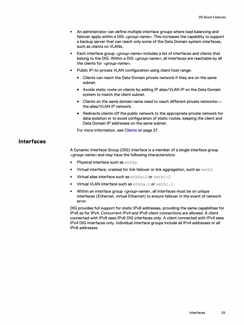
InterfacesA Dynamic Interface Group (DIG) interface is a member of a single interface group<group-name> and may have the following characteristics:
l Physical interface such as eth0al Virtual interface, created for link failover or link aggregation, such as veth1l Virtual alias interface such as eth0a:2 or veth1:2l Virtual VLAN interface such as eth0a.1 or veth1.1l Within an interface group <group-name>, all interfaces must be on unique
interfaces (Ethernet, virtual Ethernet) to ensure failover in the event of networkerror.
DIG provides full support for static IPv6 addresses, providing the same capabilities forIPv6 as for IPv4. Concurrent IPv4 and IPv6 client connections are allowed. A clientconnected with IPv6 sees IPv6 DIG interfaces only. A client connected with IPv4 seesIPv4 DIG interfaces only. Individual interface groups include all IPv4 addresses or allIPv6 addresses.
DD Boost Features
Interfaces 25

Figure 3 DIG Support for IPv4 and IPv6 Addressing
Interface EnforcementThe Dynamic Interface Group (DIG) feature gives you the ability to enforce privatenetwork connectivity, ensuring that a failed job does not reconnect on the publicnetwork after network errors. When interface enforcement is enabled, a failed job canonly retry on an alternative private network IP address. Interface enforcement is onlyavailable for clients that use DIG interfaces.
Interface enforcement is off (FALSE) by default. To enable interface enforcement,you must add the following setting to the system registry:
system.ENFORCE_IFGROUP_RW=TRUE
Note
In the previous example, ifgroup refers to the interface group.
After you've made this entry in the registry, you must do a filesys restart forthe setting to take effect.
The following illustration shows the decision flow for DIG connections. If interfaceenforcement is on (TRUE), the system always attempts to reconnect on a private IPaddress when a job fails. If a private IP address is not available, the job is canceled, anda Cancel job for non-ifgroup interface error message is generated. Ifinterface enforcement is off (FALSE), a failed job resumes using a public IP address.
DD Boost Features
26 Data Domain Boost for Partner Integration 3.4 Administration Guide

Figure 4 DIG Connection Decision
ClientsA Dynamic Interface Group (DIG) client is a member of a single interface group<group-name> and may consist of:
l A fully qualified domain name (FQDN) such as ddboost.datadomain.com
l Wild cards such as "*.datadomain.com" or “*”
l A short name for the client, such as ddboost
l Client public IP range, such as 128.5.20.0/24
Prior to write or read processing, the client requests a DIG IP address from the server.To select the client DIG association, the client information is evaluated according tothe following order of precedence (see Figure 5 on page 28):
1. IP address of the connected Data Domain system. If there is already an activeconnection between the client and the Data Domain system, and the connectionexists on the interface in the DIG, then the DIG interfaces are made available forthe client.
2. Connected client IP range. An IP mask check is done against the client source IP;if the client's source IP address matches the mask in the DIG clients list, then theDIG interfaces are made available for the client.
l For IPv4, xx.xx.xx.0/24 (128.5.20.0/24 in Figure 5 on page 28)provides a 24-bit mask against the connecting IP. The /24 represents which
DD Boost Features
Clients 27

bits are masked when the client's source IP address is evaluated for access tothe DIG. For IPv4, 16, 20, 24, 28, and 32 bit masks are supported.
l For IPv6, xxxx::0/112 provides a 112-bit mask against the connecting IP.The /112 represents what bits are masked when the client's source IP addressis evaluated for access to the DIG. For IPv6, 64, 112, and 128 bit masks aresupported.
l DD OS 6.1 supports any five masks ranging from /8 to /32.
l DD OS 6.1 supports prefix hostname matches (for example, abc_.emc.comfor hosts that have the prefix abc).
This host-range check is useful for separate VLANs with many clients where thereisn't a unique partial hostname (domain).
3. Client Name: abc-11.d1.com4. Client Domain Name: *.d1.com5. All Clients: *
Note
In a mixed network with IPv4 and IPv6 addressing, DIG client configuration should notallow IPv6 to match an IPv4 group, nor should it allow IPv4 to match an IPv6 group.Therefore, "*" should not be configured. Also, if the clients on IPv4 and IPv6 are onthe same domain name (*.domain.com, for example), only fully qualified domainnames or host-range (IP with mask) should be used.
If none of these checks find a match, DIG interfaces are not used for this client.
Figure 5 DIG Host Range for Client Selection
DD Boost Features
28 Data Domain Boost for Partner Integration 3.4 Administration Guide

Using interface groups for Managed File Replication (MFR)Interface groups can be used to control the interfaces used for DD Boost MFR, todirect the replication connection over a specific network, and to use multiple networkinterfaces with high bandwidth and reliability for failover conditions. All Data DomainIP types are supported—IPv4 or IPv6, Alias IP/VLAN IP, and LACP/failoveraggregation.
Note
Interface groups used for replication are different from the interface groups previouslyexplained and are supported for DD Boost Managed File Replication (MFR) only. Fordetailed information about using interface groups for MFR, see the EMC Data DomainBoost for Partner Integration Administration Guide or the EMC Data Domain Boost forOpenStorage Administration Guide.
Without the use of interface groups, configuration for replication requires severalsteps:
1. Adding an entry in the /etc/hosts file on the source Data Domain system for thetarget Data Domain system and hard coding one of the private LAN networkinterfaces as the destination IP address.
2. Adding a route on the source Data Domain system to the target Data Domainsystem specifying a physical or virtual port on the source Data Domain system tothe remote destination IP address.
3. Configuring LACP through the network on all switches between the Data Domainsystems for load balancing and failover.
4. Requiring different applications to use different names for the target Data Domainsystem to avoid naming conflicts in the /etc/hosts file.
Using interface groups for replication simplifies this configuration through the use ofthe DD OS System Manager or DD OS CLI commands. Using interface groups toconfigure the replication path lets you:
l Redirect a hostname-resolved IP address away from the public network, usinganother private Data Domain system IP address.
l Identify an interface group based on configured selection criteria, providing asingle interface group where all the interfaces are reachable from the target DataDomain system.
l Select a private network interface from a list of interfaces belonging to a group,ensuring that the interface is healthy.
l Provide load balancing across multiple Data Domain interfaces within the sameprivate network.
l Provide a failover interface for recovery for the interfaces of the interface group.
l Provide host failover if configured on the source Data Domain system.
l Use Network Address Translation (NAT)
The selection order for determining an interface group match for file replication is:
1. Local MTree (storage-unit) path and a specific remote Data Domain hostname
2. Local MTree (storage-unit) path with any remote Data Domain hostname
3. Any MTree (storage-unit) path with a specific Data Domain hostname
The same MTree can appear in multiple interface groups only if it has a different DataDomain hostname. The same Data Domain hostname can appear in multiple interface
DD Boost Features
Using interface groups for Managed File Replication (MFR) 29

groups only if it has a different MTree path. The remote hostname is expected to bean FQDN, such as dd890-1.emc.com.
The interface group selection is performed locally on both the source Data Domainsystem and the target Data Domain system, independent of each other. For a WANreplication network, only the remote interface group needs to be configured since thesource IP address corresponds to the gateway for the remote IP address.
IP Failover HostnameThe Failover Hostname feature lets you configure an alternative Data Domainadministrative IP address and hostname for use on failover at first connection or onfailover resulting from network errors. You can configure the alternative hostname inDNS or in the /etc/hosts file on the DD Boost client. Both IPv4 and IPv6 aresupported.
To configure the alternative hostname, append -failover to the Data Domainsystem hostname.
IPv4 Example:
10.6.109.38 ddp-880-1.datadomain.com ddp-880-110.6.109.40 ddp-880-1-failover.datadomain.com ddp-880-1-failover
IPv6 Example:
3000::230 ddp-880-2-v6.datadomain.com ddp-880-2-v63000::231 ddp-880-2-v6-failover.datadomain.com ddp-880-2-v6-failover
This feature eliminates the need to have the administrative IP address in link failovermode. In addition, you can add this failover interface to an interface group so you canconnect directly to this group without going through the system's standardadministrative interface, thereby improving load balance and throughput performance.If the initial connection fails, the failover IP address is used, if it is available. Once theconnection is established, interface group is used to select the read/write interfaces.Using the IPv4 example above:
1. The client attempts to connect to ddp-880-1.datadomain.com.
2. If the connection fails, the client attempts to connect to ddp-880-1-failover.datadomain.com.
3. If network errors occur after the initial connection is made, the connection isretried on the other interface. If the initial connection was on ddp-880-1-failover.datadomain.com, for example, the client retries the connection onddp-880-1.datadomain.com. The last address attempted on errors is alwaysthe Data Domain system IP address.
Note
On Windows 2008 R2, the “TcpTimedWaitDelay” registry entry for timing outconnections may be missing. This registry entry is essential to allow host-failoverrecovery. The name of the registry key in windows 2008 R2 is: HKLM\System\CurrentControlSet\Services\Tcpip\Parameters. This key should be set toa value of: double word "10".
DD Boost Features
30 Data Domain Boost for Partner Integration 3.4 Administration Guide

DD Boost-over-Fibre Channel TransportIn earlier versions of DD OS, all communication between the DD Boost Library and anyData Domain system was performed using IP networking. The application specified theData Domain system using its hostname or IP address. See Figure 6 on page 31.
Figure 6 DD Boost-over-IP Transport
1. Backup Server2. Applications, DD Boost Library, TCP/IP Transport3. Data Domain System4. DD Boost Service5. TCP/IP
DD OS now offers an alternative transport mechanism for communication betweenthe DD Boost Library and the Data Domain system — Fibre Channel.
Note
Windows, Linux, HP-UX, AIX, and Solaris client environments are supported.
To request access to a Data Domain system using the DD Boost-over-FC transport,the application specifies the Data Domain system using the special string DFC-<dfc-server-name>, where <dfc-server-name> is the DD Boost-over-FC server nameconfigured for the Data Domain system.
Note
Just as IP hostnames are not case-sensitive, the dfc-server-name is not case-sensitive.
DD Boost Features
DD Boost-over-Fibre Channel Transport 31

Figure 7 SCSI Commands between Backup Server and Data Domain system.
1. Backup Server2. Application, DD Boost Library, DD Boost-over-FC Transport3. Data Domain System4. DD Boost Service5. DD Boost-over-FC Server6. SCSI Commands over FC7. SCSI Processor Devices
Setting up the DD Boost-over-FC service on the Data Domain system requiresadditional configuration steps. See Configuring DD Boost-over-FC Service for details.
For the DD Boost-over-FC transport, load balancing and link-level high availability isachieved through a different means, not through Dynamic Interface Groups (DIG).See the section DD Boost-over-Fibre Channel Path Management for a description.
Note
The DD Boost-over-FC communication path applies only between the backupserver/DD Boost Library and the Data Domain system, and does not apply tocommunication between two Data Domain systems. As shown in the next figure, suchcommunication is ALWAYS over an IP network, regardless of the communication pathbetween the backup server and the Data Domain systems.
DD Boost Features
32 Data Domain Boost for Partner Integration 3.4 Administration Guide

Figure 8 Fibre Channel Communication Path
1. Backup Server2. Application, DD Boost Library3. IP or FC4. IP or FC (Control)5. Data Domain System, Replication Source6. IP ONLY (Data)7. Data Domain System, Replication Destination
DD Boost-over-Fibre Channel Path ManagementThe Dynamic Interface Group (DIG)-based mechanism described in DIG: DD Boost IPLoad Balancing and Failover is based on Ethernet interfaces and is not applicable tothe Fibre Channel transport. Instead, a different path mechanism is provided for theDD Boost-over-FC solution.
The Data Domain system advertises one or more Processor-type SCSI devices to thebackup server, over one or more physical paths. The operating system discovers alldevices through all available paths, and creates a generic SCSI device for eachdiscovered device and path.
For example, consider the case where:
l Backup server has 2 initiator HBA ports (A and B)
l Data Domain System has 2 FC target endpoints (C and D)
l Fibre Channel Fabric zoning is configured such that both initiator HBA ports canaccess both FC target endpoints
DD Boost Features
DD Boost-over-Fibre Channel Path Management 33

l Data Domain system is configured with a SCSI target access group containing:
n Both FC target endpoints on the Data Domain System
n Both initiator HBA ports
n 4 devices (0, 1, 2, and 3)
Figure 9 DD Boost-over-FC Path Management Scenario
1. Four Devices2. Backup Server3. HBA Initiator A4. HBA Initiator B5. Data Domain System6. Fibre Channel Endpoint C7. Fibre Channel Endpoint D
In this case, the backup server operating system may discover up to 16 generic SCSIdevices, one for each combination of initiator, target endpoint, and device number:
l /dev/sg11: (A, C, 0)
l /dev/sg12: (A, C, 1)
l /dev/sg13: (A, C, 2)
l /dev/sg14: (A, C, 3)
l /dev/sg15: (A, D, 0)
l /dev/sg16: (A, D, 1)
l /dev/sg17: (A, D, 2)
l /dev/sg18: (A, D, 3)
l /dev/sg19: (B, C, 0)
l /dev/sg20: (B, C, 1)
l /dev/sg21: (B, C, 2)
l /dev/sg22: (B, C, 3)
l /dev/sg23: (B, D, 0)
l /dev/sg24: (B, D, 1)
l /dev/sg25: (B, D, 2)
l /dev/sg26: (B, D, 3)
When the application requests that the DD Boost Library establish a connection to theserver, the DD Boost-over-FC Transport logic within the DD Boost Library uses SCSIrequests to build a catalog of these 16 generic SCSI devices, which are paths toaccess the DD Boost-over-FC service on the desired Data Domain System. As part of
DD Boost Features
34 Data Domain Boost for Partner Integration 3.4 Administration Guide

establishing the connection to the server, the DD Boost-over-FC Transport logicprovides to the server this catalog of paths.
Initial Path SelectionThe server maintains statistics on the DD Boost-over-FC traffic over the varioustarget endpoints and known initiators. During the connection setup procedure, PathManagement logic in the server consults these statistics, and selects the path to beused for this connection, based upon the following criteria:
l For Queue-Depth Constrained clients (see below), evenly distribute theconnections across different paths
l Choose the least busy target endpoint
l Choose the least busy initiator from among paths to the selected target endpoint
Dynamic Re-BalancingThe server periodically performs dynamic re-balancing. This involves consulting thestatistics to look for situations where:
l For Queue-Depth Constrained clients (see below), connections are distributedunequally across available paths
l Workload across target endpoints is out of balance
l Workload across initiators is out of balance
If such a situation is discovered, the server may mark one or more connections forserver-directed path migration. This is achieved by having the server request, during afuture data transfer operation, that the DD Boost Library start using a differentavailable path from the catalog for subsequent operations.
Client Path FailoverThe client may start using a different path because it is directed to do so by the serverdynamic re-balancing logic. But the client may also decide, on its own, to start using adifferent available path. This happens if the client receives errors when using theconnection's current path.
For example, assume the path catalog for a connection consists of 8 paths:
l /dev/sg21: (A, C, 0)
l /dev/sg22: (A, C, 1)
l /dev/sg23: (A, D, 0)
l /dev/sg24: (A, D, 1)
l /dev/sg25: (B, C, 0)
l /dev/sg26: (B, C, 1)
l /dev/sg27: (B, D, 0)
l /dev/sg28: (B, D, 1)
and the server selects the (A, C, 0) path during initial path selection. The DFCtransport logic in the DD Boost Library starts sending and receiving data for theconnection, using SCSI commands to /dev/sg21.
Later, the link from target endpoint C to its switch becomes unavailable, due to cablepull or some hardware failure. Any subsequent SCSI request submitted by the DFCtransport logic to /dev/sg21 will fail with an error code indicating that the SCSIrequest could not be delivered to the device.
DD Boost Features
Initial Path Selection 35

In this case, the DFC transport logic looks in the catalog of devices, for a path with adifferent physical component; that is, a different combination of initiator and targetendpoint. The SCSI request is retried on the selected path, and the process isrepeated until a path is discovered over which the SCSI request can be successfullycompleted.
Queue-Depth ConstraintsFor the purposes of the DD Boost-over-FC solution, the specific SCSI device overwhich a request is received is irrelevant. All SCSI devices are identical, destinationobjects for SCSI commands as required by the SCSI protocol. When processing aSCSI request, the server logic gives no consideration to the specific device on whichthe SCSI request arrived.
Why bother to allow for more than one device? Because certain client-side operatingsystems impose a restriction on the number of outstanding IO requests which can beconducted simultaneously over a given generic SCSI device. For example, theWindows SCSI Pass-Through Interface mechanism will only conduct 1 SCSI request ata time through each of its generic SCSI devices. This impacts the performance of theDD Boost-over FC solution, if multiple connections (e.g. backup jobs) are trying to usethe same generic SCSI device.
Additionally, the Data Domain system also imposes a limit on the number ofoutstanding IO requests per advertised SCSI device. For performance reasons withlarger workloads, multiple SCSI devices may need to be advertised on the DataDomain system.
We use the term “queue-depth” to describe the system-imposed limit on the numberof simultaneous SCSI requests on a single device. Client systems (like Windows)whose queue depth is so low as to impact performance are considered “queue-depthconstrained.”
Refer to Sizing DD Boost-over FC Device-Set on page 64 for guidance regardinghow many devices to configure based on the workload, type of Data Domain system,and whether or not the client system is queue-depth constrained.
Virtual Synthetic BackupsA synthetic full or synthetic cumulative incremental backup is a backup assembledfrom previous backups. Synthetic backups are generated from one previous,traditional full or synthetic full backup, and subsequent differential backups or acumulative incremental backup. (A traditional full backup means a non-synthesized,full backup.) A client can use the synthesized backup to restore files and directories inthe same way that a client restores from a traditional backup.
During a traditional full backup, all files are copied from the client to a backup serverand the resulting image set is sent to the Data Domain system. The files are copiedeven though those files may not have changed since the last incremental ordifferential backup. During a synthetic full backup, the previous full backup and thesubsequent incremental backups on the Data Domain system are combined to form anew, full backup. The new, full synthetic backup is an accurate representation of theclients’ file system at the time of the most recent full backup.
Because processing takes place on the Data Domain system under the direction of thebackup server instead of the client, virtual synthetic backups help to reduce thenetwork traffic and client processing. Client files and backup image sets aretransferred over the network only once. After the backup images are combined into asynthetic backup, the previous incremental and/or differential images can be expired.
DD Boost Features
36 Data Domain Boost for Partner Integration 3.4 Administration Guide

The virtual synthetic full backup is a scalable solution for backing up remote officeswith manageable data volumes and low levels of daily change. If the clients experiencea high rate of daily change, the incremental or differential backups are too large. Inthis case, a virtual synthetic backup is no more helpful than a traditional full backup.To ensure good restore performance it is recommended that a traditional full backupbe created every two months, presuming a normal weekly full and daily incrementalbackup policy.
The virtual synthetic full backup is the combination of the last full (synthetic or full)backup and all subsequent incremental backups. It is time stamped as occurring onesecond after the latest incremental backup. It does NOT include any changes to thebackup selection since the latest incremental backup.
Client Access ValidationConfiguring client access validation for DD Boost limits access to the Data Domainsystem for DD Boost clients by requiring DD Boost authentication (per connection)for:
l the initial connection to the Data Domain system
l each restart of DD Boost (Enable/Disable)
l each file system restart
l each Data Domain system reboot
The list of clients can be updated at anytime without a restart requirement, thuseliminating access validation impact on jobs in progress.
DD Boost Multiuser Data PathDD Boost multiuser data path enhancements improve storage unit isolation. Multipleusers can be configured for DD Boost access on a Data Domain system.
Storage Unit ManagementYou can use DD OS ddboost commands to configure and modify storage units,tenants, and quota limits, and to configure stream warning limits for each storage unit.
Multiuser Storage Units Access ControlThe Multiuser Storage Unit Access Control feature for DD Boost enhances the userexperience by supporting multiple usernames for the DD Boost protocol, providingdata isolation for multiple users sharing a Data Domain system. Using the DD Boostprotocol, the backup application connects to the Data Domain system with a usernameand password to support this feature. Both the username and password are encryptedusing public key cryptography.
The system administrator creates a local Data Domain user for each backupapplication to be used for their storage units. The storage unit user is required whenthe storage unit is created. When backup applications connect to the Data Domainsystem, the applications can only access the storage units owned by the usernameused to make the connection. Access to a storage unit is determined dynamically sothat changes to a storage unit's username take effect immediately. When a storageunit's username is changed to another username, all read and write operations by thebackup application using the old username fail immediately with permission errors.
DD Boost Features
Client Access Validation 37
The tenant-unit keyword is introduced to the ddboost storage-unitcommand for integration with the Data Domain Secure Multi-Tenancy feature. Onestorage unit must be configured for each tenant unit. Each tenant unit can beassociated with multiple storage units. Tenant unit association and storage unitusername ownership are independent from each other. The tenant unit is used formanagement path using the command-line-interface, but cannot be used for datapath, for example, read and write. All commands for storage units support tenantunits.
Note
For more information about tenant units, refer to the EMC Data Domain OperatingSystem Administration Guide.
Storage Unit Capacity QuotasDD OS users can use quotas to provision Data Domain system logical storage limits,ensuring that dedicated portions of the Data Domain system are available as uniquestorage units. DD Boost storage-unit quota limits may be set or removed dynamically.Quotas may also be used to provision various DD Boost storage units with differentlogical sizes, enabling an administrative user to monitor the usage of a particularstorage unit over time.
You can also configure the reported physical size; this is the size reported to thebackup application. The physical size is the Disk Pool "raw size" in NetBackup. On theData Domain system itself, the actual size is shown. The logical capacity quota is stillavailable if you configure the physical size. You can modify the reported physical sizeat a later time using ddboost storage-unit modify. You can display thereported physical size using ddboost storage-unit show.
See the ddboost, quota, and mtree sections of the EMC Data Domain OperatingSystem Command Reference Guide for details on the quota feature, and commandspertaining to quota operations.
Note
Be careful with this feature when you are using backup applications that use the DDBoost API for capacity management. The DD Boost API attempts to convert thelogical setting to a physical setting for the API by dividing the logical setting by thededuplication ratio. Logical quotas may need to be adjusted when the deduplicationratio changes.
Storage Units Stream Count ManagementYou can configure five types of stream warning limits for each storage unit:
l write-stream-soft-limit
l read-stream-soft-limit
l repl-stream-soft-limit
l combined-stream-soft-limit
l combined-stream-hard-limit
For each storage unit, stream counters are maintained to monitor backup, restore,replication-in, and replication-out data. To configure stream limits when creating astorage unit, use the ddboost storage-unit create command. To configurestream limits for an existing storage unit, use the ddboost storage-unit modify
DD Boost Features
38 Data Domain Boost for Partner Integration 3.4 Administration Guide

command. To display the active streams per storage unit, use the ddboost streamsshow active command.
When any stream count exceeds the warning limit quota, an alert is generated. Thealert automatically clears once the stream limit returns below the quota for over 10minutes.
Any of these stream warning limits can also be set to none.
Note
DD Boost backup applications are expected to reduce their workload to remain belowthe stream warning quotas. You can reconfigure the warning limit to avoid exceedingthe quotas.
For more information about configuring stream limits, see Configuring Storage Unitswith Stream Limits (Optional) on page 45.
DD Boost Features
Storage Units Stream Count Management 39

DD Boost Features
40 Data Domain Boost for Partner Integration 3.4 Administration Guide

CHAPTER 3
Preparing the Data Domain System for DDBoost
Note
Complete descriptions of commands used in this guide are provided in the EMC DataDomain Operating System Command Reference Guide.
This chapter covers the following topics:
l Enabling DD Boost on a Data Domain System.................................................... 42l Assigning Multiple Users to DD Boost................................................................ 42l Creating Storage Units ......................................................................................43l Configuring Logical Quotas for Storage Units (Optional) .................................. 44l Configuring Storage Units with Stream Limits (Optional).................................. 45l Configuring Distributed Segment Processing.....................................................46l Configuring Dynamic Interface Groups ..............................................................47l Using Dynamic Interface Groups for MFR..........................................................50l Configuring MFR................................................................................................60l Configuring Client Access Validation.................................................................. 61l Configuring DD Boost-over-FC Service............................................................. 62l Setting Global Authentication and Encryption....................................................70
Preparing the Data Domain System for DD Boost 41

Enabling DD Boost on a Data Domain SystemEvery Data Domain system that is enabled for Data Domain Boost deduplication musthave a unique name. You can use the DNS name of the Data Domain system, which isalways unique.
Procedure
1. On the Data Domain system, log in as an administrative user.
2. Verify that the file system is enabled and running by entering:
# filesys statusThe file system is enabled and running.
3. Add the DD Boost license using the license key that Data Domain provided:
# license add license_codeLicense “ABCE-BCDA-CDAB-DABC” added.
4. Enable DD Boost deduplication by entering:
# ddboost enableDD Boost enabled
Note
l The users must be configured in the backup application to connect to theData Domain system. For more information, refer to the EMC Data DomainOperating System Administration Guide.
l Multiple users can be configured for DD Boost access on a Data Domainsystem. The username, password, and role must have already been set up onthe Data Domain system using the DD OS command:
user add <user> [password <password>][role {admin | security | user | backup-operator | data-access}][min-days-between-change <days>] [max-days-between-change <days>][warn-days-before-expire <days>] [disable-days-after-expire <days>][disable-date <date>]
For example, to add a user with a login name of jsmith and a password ofusr256 with administrative privilege, enter:
# user add jsmith password usr256 role admin
Then, to add jsmith to the DD Boost user list, enter:
# ddboost user assign jsmith
Assigning Multiple Users to DD BoostAs system administrator, you need to create a local Data Domain system user for eachbackup application to use with their storage units. The storage units are either createdwith a username, or can be modified to change the username for an upgrade. Storageunits are accessible only to applications with the username that owns the storage unit.Each storage unit is owned by one username, and the same username can ownmultiple storage units. The application passes the username and password to DDBoost, and DD Boost passes them to the Data Domain system when attempting toconnect to the Data Domain system. The Data Domain system then authenticates the
Preparing the Data Domain System for DD Boost
42 Data Domain Boost for Partner Integration 3.4 Administration Guide

username and password. The username and password can be shared by differentapplications.
When a storage unit is created with a valid Data Domain system local user but notassigned to DD Boost, the user is automatically added to the DD Boost users list in thesame way that a user is added via the ddboost user assign command. If astorage unit is created without specifying the owning username, the current DD Boostuser name is assigned as owner.
To assign and add one or more users to the DD Boost users list, enter:
# ddboost user assign user1 user2User "user1" assigned to DD Boost.User "user2" assigned to DD Boost.
To verify and display the users in the users list, enter:
# ddboost user show
DD Boost user Default tenant-unit Using Token Access------------- ------------------- ------------------ddbu1 Unknown Yesddbu2 Unknown -ddbu3 Unknown Yes ddbu4 Unknown -ddbu5 Unknown -ddbu6 Unknown -ddbu7 Unknown Yesddbu8 Unknown -------------- ------------------- ------------
To unassign and delete the user from the users list, enter:
# ddboost user unassign user1User "user1" unassigned from DD Boost.
Creating Storage UnitsYou need to create one or more storage units on each Data Domain system enabledfor DD Boost.
Procedure
1. To create a storage unit on the Data Domain system, enter:
# ddboost storage-unit create NEW_STU1 user user1Created storage-unit "NEW_STU1" for "user1".
Note
A storage unit name must be unique on any given Data Domain system.However, the same storage unit name can be used on different Data Domainsystems. The username owns the storage unit and ensures that onlyconnections with this username's credentials are able to access this storageunit.
See the section on ddboost storage-unit in the EMC Data DomainOperating System Command Reference Guide for details on command options.
Preparing the Data Domain System for DD Boost
Creating Storage Units 43

Note
When a storage-unit is created with a valid Data Domain local user who is notalready assigned to DD Boost, the user is automatically added to the DD Boostuser list in the same way that a ddboost user is added to the user list via theddboost user assign command.
2. Repeat the above step for each Boost-enabled Data Domain system.
3. To modify a storage unit on the Data Domain system, enter:
# ddboost storage-unit modify NEW_STU1 user user2Storage-unit "NEW_STU1" modified for user "user2".
Note
The ddboost storage-unit modify command allows the backupapplication to change the user-name ownership of the storage unit. Changingthe username does not need to change attributes of every file on the storageunit, therefore it is fast.
4. To display the users list for the storage units, enter:
# ddboost storage-unit showName Pre-Comp (GiB) Status User Report Physical Size (MiB)----------------- -------------- ------ -------- ---------------backup 3.0 RW sysadmin -DDBOOST_STRESS_SU 60.0 RW sysadmin -task2 0.0 RW sysadmin -tasking1 0.0 RW sysadmin -DD1 0.0 RW sysadmin -D6 5.0 RW sysadmin -TEST_DEST 0.0 D sysadmin -STU-NEW 0.0 D ddu1 -getevent 0.0 RW ddu1 -DDP-5-7 120.0 RW sysadmin -TESTME 150.0 RW sysadmin -DDP-5-7-F 100.0 RW sysadmin -testSU 0.0 RW sysadmin 200----------------- -------------- ------ -------- ---------------D : DeletedQ : Quota DefinedRO : Read OnlyRW : Read WriteRD : Replication Destination
Configuring Logical Quotas for Storage Units (Optional)The storage on a Data Domain system can be provisioned through optional quota limitsfor a storage-unit. Quota limits can be specified either at the time of creation of astorage-unit, or later through separate commands. For more information, refer to thesections on quotas and ddboost in the EMC Data Domain Operating System CommandReference Guide.
Procedure
1. To enable quota limits on the Data Domain system, enter:
# quota enable2. To configure quota limits at the time of creation of a storage unit, specify the
quota-soft-limit and quota-hard-limit values with the following command:
Preparing the Data Domain System for DD Boost
44 Data Domain Boost for Partner Integration 3.4 Administration Guide

# ddboost storage-unit create storage-unit[quota-soft-limit n {MiB|GiB|TiB|PiB}] [quota-hard-limit n {MiB|GiB|TiB|PiB}]
3. To modify quota limits after they've been created, specify the new quota-soft-limit and quota-hard-limit values with the following command:
# ddboost storage-unit modify storage-unit[quota-soft-limit {n {MiB|GiB|TiB|PiB}|none}] [quota-hard-limit {n {MiB|GiB|TiB|PiB}|none}]
4. To verify the quota limits of a storage unit:
# quota show storage-units storage-unit-list
Configuring Storage Units with Stream Limits (Optional)The system administrator configures stream warning limits against each storage-unitfor each of the five limits:
l write-stream-soft-limit
l read-stream-soft-limit
l repl-stream-soft-limit
l combined-stream-soft-limit
l combined-stream-hard-limit
You can assign four types of soft stream warning limits against each storage-unit(read, write, replication, and combined), and you can assign a combined hard streamlimit. Assigning a hard stream limit per storage-unit enables you to fail new DD Booststreams when the limit is exceeded, including read streams, write streams, andreplication streams. The hard stream limit is detected before the stream operationstarts. The hard stream limit cannot exceed the capacity of the Data Domain systemmodel, and it cannot be less than any other single limit (read, write, replication, orcombined).
When any stream count exceeds the warning limit quota, an alert is generated. Thealert automatically clears once the stream limit returns below the quota for over 10minutes.
Note
DD Boost users are expected to reduce the workload to remain below the streamwarning quotas or the system administrator can change the warning limit configuredto avoid exceeding the limit.
To create a storage unit with stream limits, you could enter:
# ddboost storage-unit create NEW_STU0 user user2 write-stream-soft-limit 5 read-stream-soft-limit 1 repl-stream-soft-limit 2 combined-stream-hard-limit 10Created storage-unit "NEW_STU0" for "user2".Set stream warning limits for storage-unit "NEW_STU0".
To modify the stream limits for a storage unit, you could enter:
# ddboost storage-unit modify NEW_STU1 write-stream-soft-limit 3 read-stream-soft-limit 2 repl-stream-soft-limit 1 combined-stream-hard-limit 8NEW_STU1: Stream soft limits: write=3, read=2, repl=1, combined=none
Setting a limit to none disables that limit.
To display the DD Boost stream limits for all the active storage units, enter ddbooststreams show active. To display the DD Boost stream limits for a specific storageunit, enter:
Preparing the Data Domain System for DD Boost
Configuring Storage Units with Stream Limits (Optional) 45

# ddboost streams show active storage-unit STU-1
--------- Active Streams -------- --------- Soft Limits -------- - Hard Limit -Name Read Write Repl-out Repl-in Read Write Repl Combined Combined----- ---- ----- -------- ------- ---- ----- ---- -------- --------------STU-1 0 0 0 0 - - - - 25----- ---- ----- -------- ------- ---- ----- ---- -------- --------------DD System Stream Limits: read=30 write=90 repl-in=90 repl-out=82 combined=90
Note
The Data Domain system stream limits displayed in the output are based on the typeof the Data Domain system.
To display the DD Boost stream limits history for a specific storage unit for a specifictime, enter:
# ddboost streams show history storage-unit NEW_STU0 last 1hoursINTERVAL: 10 mins"-" indicates that the data is not available for the intervals
Storage-Unit: "NEW_STU0"Date Time read write repl-out repl-inYYYY/MM/DD HH:MM streams streams streams streams----------------- ------- ------- --------- --------2013/08/29 12:00 0 0 0 02013/08/29 12:10 0 0 0 02013/08/29 12:20 0 1 0 02013/08/29 12:30 0 2 0 02013/08/29 12:40 0 2 0 02013/08/29 12:50 0 1 0 02013/08/29 13:00 0 0 0 0----------------- ------- ------- --------- --------
Configuring Distributed Segment ProcessingThe distributed segment processing option is configured on the Data Domain systemand applies to all the backup servers and the DD Boost libraries installed on them.
The option can be configured using the following command:
# ddboost option set distributed-segment-processing {enabled | disabled}
Note
Enabling or disabling the distributed segment processing option does not require arestart of the Data Domain file system.
Distributed segment processing is supported with version 2.2 or later of the DD Boostlibraries communicating with a Data Domain system that is running DD OS 4.8 or later.
Distributed segment processing is enabled by default on a system initially installedwith DD OS 5.2. If a system is upgraded from DD OS 5.1, 5.0.x or 4.9.x to DD OS 5.2,distributed segment processing is left in its previous state.
Distributed segment processing is enabled (and cannot be disabled) on DD OS 5.5.1.0and earlier.
Distributed segment processing is enabled by default for Solaris plug-ins running on aSPARC T4 or T5 processor and running Solaris 11 (with SRU2 or later) or Solaris 11.1or later.
Preparing the Data Domain System for DD Boost
46 Data Domain Boost for Partner Integration 3.4 Administration Guide
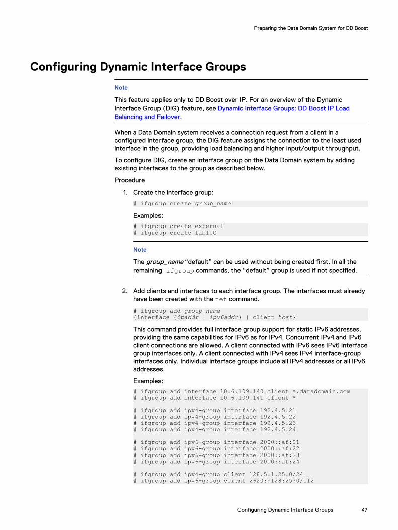
Configuring Dynamic Interface Groups
Note
This feature applies only to DD Boost over IP. For an overview of the DynamicInterface Group (DIG) feature, see Dynamic Interface Groups: DD Boost IP LoadBalancing and Failover.
When a Data Domain system receives a connection request from a client in aconfigured interface group, the DIG feature assigns the connection to the least usedinterface in the group, providing load balancing and higher input/output throughput.
To configure DIG, create an interface group on the Data Domain system by addingexisting interfaces to the group as described below.
Procedure
1. Create the interface group:
# ifgroup create group_name
Examples:
# ifgroup create external# ifgroup create lab10G
Note
The group_name “default” can be used without being created first. In all theremaining ifgroup commands, the “default” group is used if not specified.
2. Add clients and interfaces to each interface group. The interfaces must alreadyhave been created with the net command.
# ifgroup add group_name{interface {ipaddr | ipv6addr} | client host}
This command provides full interface group support for static IPv6 addresses,providing the same capabilities for IPv6 as for IPv4. Concurrent IPv4 and IPv6client connections are allowed. A client connected with IPv6 sees IPv6 interfacegroup interfaces only. A client connected with IPv4 sees IPv4 interface-groupinterfaces only. Individual interface groups include all IPv4 addresses or all IPv6addresses.
Examples:
# ifgroup add interface 10.6.109.140 client *.datadomain.com# ifgroup add interface 10.6.109.141 client *
# ifgroup add ipv4-group interface 192.4.5.21# ifgroup add ipv4-group interface 192.4.5.22# ifgroup add ipv4-group interface 192.4.5.23# ifgroup add ipv4-group interface 192.4.5.24
# ifgroup add ipv6-group interface 2000::af:21# ifgroup add ipv6-group interface 2000::af:22# ifgroup add ipv6-group interface 2000::af:23# ifgroup add ipv6-group interface 2000::af:24
# ifgroup add ipv4-group client 128.5.1.25.0/24# ifgroup add ipv6-group client 2620::128:25:0/112
Preparing the Data Domain System for DD Boost
Configuring Dynamic Interface Groups 47

Note
l If no group_name is specified, the default group is used.
l IPv6 addresses can be entered using upper- or lower-case characters andwith multiple zeroes.
l These commands properly detect any mismatches with IPv4 or IPv6interfaces.
3. Select one interface on the Data Domain system to register with the backupapplication. It is recommended that you create a failover aggregated interfaceand register that interface with the backup application.
Note
It is not mandatory to choose an interface from the interface group to registerwith the backup application. An interface that is not part of the interface groupcan also be used to register with the backup application.EMC recommends that the interface be registered with a resolvable name usingDNS or any other name resolution mechanism.
Note
The interface registered with the backup application is used by the backupapplication and its DD Boost libraries to communicate with the Data Domainsystem. If this interface is not available, then backups to that Data Domainsystem are not possible.
4. Once an interface and client are configured, the group is automatically enabled.Check the status (enabled or disabled) of the interface group:
# ifgroup status [group_name]Status of ifgroup “default” is “enabled”
Note
If no group_name is specified, the default group is used.
5. Verify the entire configuration of all the groups with interfaces and clients:
# ifgroup show config allResults
Sample output is displayed in the following table.
Group Name Status Interfaces Clients Count Count-----------------------------------------------------------------default enabled 2 1external enabled 2 1lab10G enabled 2 2-----------------------------------------------------------------Group Name Status Interfaces ------------------------------------------------------------default enabled 10.6.109.141default enabled 10.6.109.41external enabled 10.6.109.140 external enabled 10.6.109.142lab10G enabled 192.168.1.220lab10G enabled 192.168.1.221
Preparing the Data Domain System for DD Boost
48 Data Domain Boost for Partner Integration 3.4 Administration Guide

-----------------------------------------------------------------Group Name Status Clients ------------------------------------------------------------default enabled *external enabled *.datadomain.comlab10G enabled ddboost-dl.datadomain.com lab10G enabled yellowmedia.datadomain.com------------------------------------------------------------
Note
Exact name matches are done first, followed by partial name matches. So, in theexample above, ddboost-dl.datadomain is found in the lab10G group.
Modifying an Interface GroupAfter the interface group is set up, you can add or delete interfaces from the group.The following example shows how to remove an interface from the configuredinterface group on the Data Domain system.
Procedure
1. Make sure that no jobs are active from the backup application to the DataDomain system on the interface you are removing from the group. You can dothis from the Data Domain system by checking the status of existingconnections in the interface group by enter the following command:
# ddboost show connections
Note
Refer to documentation about the DD860 Extended Retention system (formerlythe DD860 Archiver Administration Guide) for an example of this command on anactive tier.
2. Delete an interface or client from group-name or default group on the DataDomain system.
# ifgroup del default interface 10.6.109.144
After this, the interface is released from the group and would no longer be usedby the DD Boost Storage Server for any jobs from the backup servers.
Note
Removing the interface registered with the backup application makes the DataDomain system inaccessible to the backup servers. The configuration of theinterface group on the Data Domain system is not deleted.
Results
To make any changes to any interface that is added to the interface group on the DataDomain system at the network layer, remove the interface from the group and add itback.
Preparing the Data Domain System for DD Boost
Modifying an Interface Group 49

Note
If you make changes using the net command that modifies the interfaces, such asenabling an interface that is configured for interface group, execute the ddboostshow connections command to update the load-balancing view. Updating the loadbalancing view allows the interface group to use the interface.
Removing an Interface GroupThe following example illustrates removing a configured interface group on the DataDomain system.
Procedure
1. Make sure that no jobs are active from the backup application to the DataDomain system. Check the status of connections in the interface group by usingthe following command on a Data Domain system:
# ifgroup show connections2. Ensure there are no pending jobs from backup servers connected to the Data
Domain system.
3. Disable the group-name or default group on the system:
# ifgroup disable <group-name>4. Reset the interface group:
# ifgroup reset <group-name>Results
All the interfaces are released from the group. However, backup servers can stillaccess the DD Boost storage server on the Data Domain system on the interfaceregistered with the backup application.
When a group is no longer needed, use the destroy option to remove the group fromthe configuration:
# ifgroup destroy group-name
Example:
# ifgroup destroy external
Clients are matched to a group by their hostname independent of the group status(enabled/disabled). Therefore, disabling a group will not force a client to use adifferent group. When a client is found in a disabled group, it will use the registeredinterface and stay on the original connection.
Note
You can also manage interface groups from the System Manager Data ManagementDD Boost view. (See the EMC Data Domain Operating System Administration Guide).
Using Dynamic Interface Groups for MFRThe Dynamic Interface Group (DIG) feature provides the ability to control theinterfaces used for DD Boost MFR to direct the replication connection over a specificnetwork, and to use multiple network interfaces with high bandwidth and reliability forfailover conditions. All Data Domain IP types are supported—IPv4 or IPv6, Alias IP/VLAN IP, and LACP/failover aggregation.
Preparing the Data Domain System for DD Boost
50 Data Domain Boost for Partner Integration 3.4 Administration Guide

Note
The DIG feature is supported for DD Boost Managed File Replication (MFR) only.
Without the use of interface groups, configuration for replication requires severalsteps:
1. Adding an entry in the /etc/hosts file on the source Data Domain system for thetarget Data Domain system and hard coding one of the private LAN networkinterfaces as the destination IP address.
2. Adding a route on the source Data Domain system to the target Data Domainsystem specifying a physical or virtual port on the source Data Domain system tothe remote destination IP address.
3. Configuring LACP through the network on all switches between the Data Domainsystems for load balancing and failover.
4. Requiring different applications to use different names for the target Data Domainsystem to avoid naming conflicts in the /etc/hosts file.
Using interface groups for replication simplifies this configuration through the use ofthe DD OS System Manager or DD OS CLI commands. Using interface groups toconfigure the replication path lets you:
l Redirect a hostname-resolved IP address away from the public network, usinganother private Data Domain system IP address.
l Identify an interface group based on configured selection criteria, providing asingle interface group where all the interfaces are reachable from the target DataDomain system.
l Select a private network interface from a list of interfaces belonging to a group,ensuring that the interface is healthy.
l Provide load balancing across multiple Data Domain interfaces within the sameprivate network.
l Provide a failover interface for recovery for the interfaces of the interface group.
l Provide host failover if configured on the source Data Domain system.
l Use Network Address Translation (NAT)
The selection order for determining an interface group match for file replication is:
1. Local MTree (storage-unit) path and a specific remote Data Domain hostname
2. Local MTree (storage-unit) path with any remote Data Domain hostname
3. Any MTree (storage-unit) path with a specific Data Domain hostname
The same MTree can appear in multiple interface groups only if it has a different DataDomain hostname. The same Data Domain hostname can appear in multiple interfacegroups only if it has a different MTree path. The remote hostname is expected to bean FQDN, such as dd890-1.emc.com.
The interface group selection is performed locally on both the source Data Domainsystem and the target Data Domain system, independent of each other. For a WANreplication network, only the remote interface group needs to be configured since thesource IP address corresponds to the gateway for the remote IP address.
Replication over LANsTo configure interface groups for replication over a LAN:
Preparing the Data Domain System for DD Boost
Replication over LANs 51
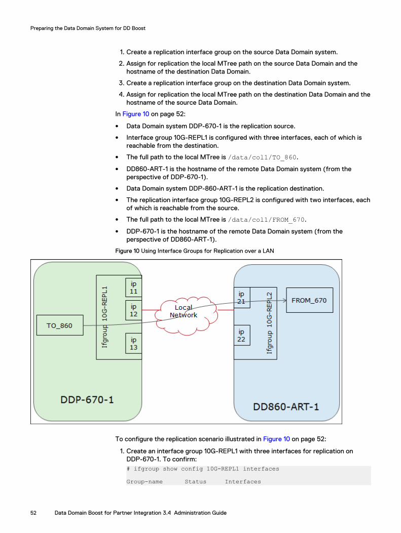
1. Create a replication interface group on the source Data Domain system.
2. Assign for replication the local MTree path on the source Data Domain and thehostname of the destination Data Domain.
3. Create a replication interface group on the destination Data Domain system.
4. Assign for replication the local MTree path on the destination Data Domain and thehostname of the source Data Domain.
In Figure 10 on page 52:
l Data Domain system DDP-670-1 is the replication source.
l Interface group 10G-REPL1 is configured with three interfaces, each of which isreachable from the destination.
l The full path to the local MTree is /data/col1/TO_860.
l DD860-ART-1 is the hostname of the remote Data Domain system (from theperspective of DDP-670-1).
l Data Domain system DDP-860-ART-1 is the replication destination.
l The replication interface group 10G-REPL2 is configured with two interfaces, eachof which is reachable from the source.
l The full path to the local MTree is /data/col1/FROM_670.
l DDP-670-1 is the hostname of the remote Data Domain system (from theperspective of DD860-ART-1).
Figure 10 Using Interface Groups for Replication over a LAN
To configure the replication scenario illustrated in Figure 10 on page 52:
1. Create an interface group 10G-REPL1 with three interfaces for replication onDDP-670-1. To confirm:# ifgroup show config 10G-REPL1 interfaces
Group-name Status Interfaces
Preparing the Data Domain System for DD Boost
52 Data Domain Boost for Partner Integration 3.4 Administration Guide

------------- ------- -----------10G-REPL1 enabled 172.29.0.1110G-REPL1 enabled 172.29.0.1210G-REPL1 enabled 172.29.0.13------------- ------- -----------
2. Assign the full MTree path and remote hostname for replication:# ifgroup replication assign 10G-REPL1 mtree /data/col1/TO_860 remote dd860-art-1Assigned replication mtree "/data/col1/TO_860" with remote "dd860-art-1" to ifgroup "10G-REPL1".
To confirm:# ifgroup show config 10G-REPL1 replication
Group-name Status Replication Mtree Replication Remote Host------------- ------- ----------------- -----------------------10G-REPL1 enabled /data/col1/TO_860 dd860-art-1------------- ------- ----------------- -----------------------
3. Create an interface group 10G-REPL2 with two interfaces for replication onDD860-ART-1. To confirm:# ifgroup show config 10G-REPL2 interfaces
Group-name Status Interfaces------------- ------- -----------10G-REPL2 enabled 172.29.0.2110G-REPL2 enabled 172.29.0.22------------- ------- -----------
4. Assign the full MTree path and remote hostname for replication:# ifgroup replication assign 10G-REPL2 mtree /data/col1/FROM_670 remote ddp-670-1Assigned replication mtree "/data/col1/FROM_670" with remote "ddp-670-1 to ifgroup "10G-REPL2".
To confirm:# ifgroup show config 10G-REPL2 replication
Group-name Status Replication Mtree Replication Remote Host------------- ------- ------------------- -----------------------10G-REPL2 enabled /data/col1/FROM_670 ddp-670-1------------- ------- ------------------- -----------------------
Replication over WANsThere are two options for configuring interface groups for replication over WANs:
l Use the interface group on the destination only and let the source Data Domainsystem select the source interface based on the route configuration.
l Use interface groups on both the source and destination systems, and make surethat the IP on the source can reach the IP on the destination—you can verify thatby using a trace route from both the source and destination.
Figure 11 on page 54 shows how interface groups can be used for replication overWANS:
l Data Domain system DDP-670-1 is the replication source.
l Interface group 10G-REPL3 is configured with two interfaces, each of which isreachable from one destination IP address.
l The full path to the local MTree is /data/col1/TO_890.
l DDP-890-1 is the hostname of the remote Data Domain system (from theperspective of DDP-670-1).
Preparing the Data Domain System for DD Boost
Replication over WANs 53

l Data Domain system DDP-890-1 is the replication destination.
l Interface group 10G-REPL4 is configured with two interfaces, each of which isreachable from one source IP address.
l The full path to the local MTree is /data/col1/FROM_670.
l DDP-670-1 is the hostname of the remote Data Domain system (from theperspective of DDP-890-1).
l There are two networks—WAN Network A and WAN Network B—in the sameinterface group.
Figure 11 Using Interface Groups for Replication over WANs
Other Supported Use CasesBackup applications need to replicate data over their own networks and use multiplenetwork interfaces with high bandwidth and failover capability. To support theseneeds, interface groups provide support for various replication paths, includingmultiple customer network, fan-out, and cascading paths.
Multiple Customer NetworkA service provider with multiple customers may require that customers be able toreplicate data across their own networks. In Figure 12 on page 55, one customer isusing Network A for replication of MTree11 from Data Domain System 1 (DDR1) toSystem 2 (DDR2), as well as MTree2 from System 2 to System 1. Another customer isusing Network B for replication of MTree33 from System 1 to System 2.
Preparing the Data Domain System for DD Boost
54 Data Domain Boost for Partner Integration 3.4 Administration Guide

Figure 12 Using Interface Groups for Replication over Multiple Customer Networks
These replication paths have the same source and destination Data Domain systems,so the interface group is configured based on the MTree paths. For Network A,Ifgroup-K is configured based on the MTree11 and MTree22 paths, and Ifgroup-J isconfigured based on the MTree1 and MTree2 paths. For Network B, Ifgroup-L isconfigured based on the MTree33 path, and Ifgroup-R is configured based on theMTree3 path.
Fan-OutIn Figure 13 on page 56, MTree2 is replicated from Data Domain System 1 (DDR1) toSystem 2 (DDR2), and from System 1 to System 3 (DDR3).
Preparing the Data Domain System for DD Boost
Other Supported Use Cases 55

Figure 13 Using Interface Groups for Fan-Out Replication
Because the same source MTree is used, the interface group is configured based onthe hostname of the remote Data Domain system. For Network A, Ifgroup-K isconfigured based on the hostname of Data Domain System 2, and Ifgroup-J isconfigured based on the hostname of Data Domain System 1. For Network B, Ifgroup-L is configured based on the hostname of Data Domain System 3, and Ifgroup-R isconfigured based on the hostname of Data Domain System 1.
CascadingIn Figure 14 on page 57, MTree1 is replicated from Data Domain System 1 (DDR1) toSystem 2 (DDR2), then to System 3 (DDR3).
Preparing the Data Domain System for DD Boost
56 Data Domain Boost for Partner Integration 3.4 Administration Guide

Figure 14 Using Interface Groups for Cascading Replication
For Network A, Ifgroup-J is configured based on the hostname of remote Data DomainSystem 3, and Ifgroup-K is configured based on the hostname of remote Data DomainSystem 2 or the path of MTree13. For Network C, Ifgroup-H is configured based onthe hostname of Data Domain System 1, and Ifgroup-Q is configured based on thehostname of remote Data Domain System 2 or the path of MTree1.
Replication Failover HostnameSupported only for DD Boost file replication, the Replication Failover Hostnamefeature provides the same functionality as the Failover Hostname feature for backup(see IP Failover Hostname on page 30 for details).
For replication, you configure the destination host name (remote Data Domainsystem) in the /etc/hosts file on the source Data Domain system as a failover namewith another IP address that exists on the destination system.
These replication connections use the host-“failover” retry capability:
l File replication commands executed prior to the start of replication:
n Creating a new file
n Deleting a file
n Finding a synthetic base file
l Requesting an interface group IP address from the destination system
Interface-group replication over IPv4 supports replication with NAT. The configurationis on the destination Data Domain system, where the source Data Domain queries foran IP address. Therefore, the destination Data Domain needs to have an interface
Preparing the Data Domain System for DD Boost
Replication Failover Hostname 57

group with the IP addresses that the source Data Domain system can use (before NATconversion) to reach the destination. For example:
Source DD -> 128.222.4.15 --NAT-> 192.169.172.8 Target DDSource DD -> 128.222.4.16 --NAT-> 192.169.172.9 Target DD
On the remote Data Domain system:
net config ethx:1 128.222.4.15 << on the ethx of IP 192.169.172.8net config ethy:1 128.222.4.16 << on the ethy of IP 192.169.172.8
Create an interface-group replication group and add the new IP addresses:
ifgroup create nat-replifgroup add nat-repl interface 128.222.4.15ifgroup add nat-repl interface 128.222.4.16ifgroup replication assign remtoe <source DD hostname>
Network Address Translation (NAT) SupportInterface groups support Network Address Translation (NAT) for MFR. NAT iscurrently supported only with IPv4 addressing.
Interface group replication with NAT requires the public IP address, not the local IPaddress, for the destination interface group.
Note
On a Data Domain system, alias IP addresses can be configured on an active interfacewith IP addresses that are not reachable. In Figure 15 on page 59, IP addresses215.55.7.20 and 215.55.7.21 are aliases, configured strictly for interface group use.
To configure interface groups to support NAT:
1. Create a “natlan” interface group.
2. Create an alias IP address for the local interface.
3. Assign the external public IP address to the alias.
4. Add each new IP address to the “natlan” interface group.
5. Add replication selection (local MTree path and/or remote Data Domain hostname.
6. For the source Data Domain for replication, the source IP address of theconnection needs to use the local private network.
7. For the destination Data Domain for replication, the destination IP address of theconnection needs to use the public network.
In Figure 15 on page 59, DD1 and DD2 are each in a private network. Replication withNAT can be used in both directions, where the MTree name selects between the twointerface groups. Only the source Data Domain system uses an interface group toselect the source and destination IP. The source Data Domain queries the remote DataDomain for an IP address to use, so all IP addresses must always be from theperspective of the source Data Domain. Replication from DD1 on Network-1 to DD2 onNetwork-2 uses Local-lan2 with natlan2 to select both source and destination IPaddresses for connection. Replication from DD2 on Network-2 to DD1 on Network-1uses Local-lan1 with natlan1. Therefore, only the remote query for interface group IPaddresses must adjust for NAT configuration.
Preparing the Data Domain System for DD Boost
58 Data Domain Boost for Partner Integration 3.4 Administration Guide

Note
Replication with NAT requires that the following system registry entry be enabled (it isdisabled by default):system.IFGROUP_REPLICATION_NAT_SUPPORT = TRUE
Figure 15 Interface Group Replication Support for NAT
Resolving Backup/Replication ConflictsWhen the registered administrative interface for backup is used for interface groupreplication, backup jobs erroneously select the replication interface group. To avoidthis problem, add a client with the name "no-auto-detect" to the interface group thathas the administrative IP address. To allow for multiple replication groups, "no-auto-detect" is internally appended with a number.
To add the client:
Preparing the Data Domain System for DD Boost
Resolving Backup/Replication Conflicts 59

# ifgroup add repl-group client no-auto-detectAdded client "no-auto-detect" to ifgroup "repl-group".
# ifgroup show config repl-group clients
Group-name Status DD Boost Clients---------- ------- ---------------------------repl-group enabled no-auto-detect.4---------- ------- ---------------------------
To remove the client:
# ifgroup del repl-group client no-auto-detect.4Deleted client "no-auto-detect.4" from ifgroup "repl-group".
Configuring MFR
Enabling Low-Bandwidth OptimizationTo enable the low-bandwidth option for managed file replication, enter:
# ddboost file-replication option set low-bw-optim enabledLow bandwidth optimization enabled for optimized duplication.
Note
Enabling or disabling the low-bandwidth optimization option does not require a restartof the Data Domain file system.
Low-bandwidth optimization can also be monitored and managed from the EnterpriseManager Data Management DD Boost view. (See the EMC Data Domain OperatingSystem Administration Guide.)
No configuration changes are necessary on the backup server as this feature istransparent to the backup applications.
Note
l Enabling this feature takes additional resources (CPU and memory) on the DataDomain system, so it is recommended that this option be used only when managedfile replication is being done over low-bandwidth networks with less than 6 Mbpsaggregate bandwidth.
l The low-bandwidth option for managed file replication is supported only forstandalone Data Domain systems.
l Low-bandwidth optimization is not supported on Data Domain Extended Retentionsystems.
Enabling EncryptionTo enable the encrypted managed file replication option, enter:
# ddboost file-replication option set encryption enabled
The output indicates that the encryption you requested was enabled.
No configuration changes are necessary on the backup server as this feature istransparent to the backup application. Turning on this feature takes additionalresources (CPU and memory) on Data Domain system.
Preparing the Data Domain System for DD Boost
60 Data Domain Boost for Partner Integration 3.4 Administration Guide

Enabling IPv6 SupportThe existing Managed File Replication commands now include IPv4 or IPv6functionality. For DD Boost to provide IPv6 support for managed file replication, a newkeyword ipversion is added into the registry to provide an option to support IPv6network. The IPv6 keyword variable is controlled through the ddboost file-replication option set command keyword ipversion. If the option ipversion isipv6, IPv6 is the preferred IP address type for managed file-replication. If the ipversionoption is ipv4, then IPv4 is the preferred IP address type for managed file-replication.If a preferred IP address is not specified, the default is IPv4.
To set the preferred IP version for DD Boost file replication to IPv6, enter:
# ddboost file-replication option set ipversion ipv6Ipversion for file-replication set to "ipv6"
To display the current values for the DD Boost file-replication options, enter:
# ddboost file-replication option show ipversionIpversion for file-replication is: ipv6
To reset DD Boost file replication option to the default value IPv4, enter:
# ddboost file-replication option reset ipversion
Changing the MFR TCP PortChanging the MFR TCP port affects all replication, not just MFR. Changing the MFRTCP port requires a restart of the Data Domain file system and should be a plannedevent.
To change the Replication TCP port from the default of 2051 to port-number, enterthe following commands on both the source and destination Data Domain systems:
# replication option set listen-port port-number# filesys restart
Note
Managed file replication and directory replication both use listen-port option.Managed file replication uses the replication option set listen-portcommand on both the source and destination to specify the port on which thedestination listens and the port on which the source connects. Directory replicationuses the listen-port option to specify only the replication destination server listen-port. On the replication source, the connection port for a specific destination isentered using the replication modify command.
l For more information on these topics, see the EMC Data Domain Operating SystemCommand Reference Guide.
Configuring Client Access ValidationConfiguring client access control for DD Boost limits access to the Data Domainsystem for DD Boost clients and removes dependency on the DNS. By default, if noclients are added to the clients list when DD Boost is enabled, all clients will beautomatically included in the clients list. By default a * wildcard is used.
To restrict access, remove the * wildcard from the list and then add your new clients.
Preparing the Data Domain System for DD Boost
Enabling IPv6 Support 61

The backup server client list may contain both fully qualified domain names or shortnames. The backup host's fully qualified domain name needs to be correctlyconfigured for reverse lookup in DNS.
To delete all clients from the DD Boost clients list, enter:
# ddboost clients delete client-list
Optionally, to delete all clients previously added and reset the DD Boost clients list,enter:
# ddboost client reset
Clients can be added as both fully qualified domain names and short names. To addclients to the DD Boost clients list, enter:
# ddboost clients add client-list [encryption-strength {none | medium | high} authentication-mode {one-way | two-way | anonymous | kerberos}]
Example:
# ddboost clients add ddboost-dl.emc.com ddboost-dlAdded "ddboost-dl.emc.com" Added "ddboost-dl"
To view the DD Boost clients list, enter:
# ddboost clients show config
Client Encryption Strength Authentication Mode----------------------- ------------------- -------------------* none none*.corp.emc.com medium anonymousrtp-ost-ms02.domain high anonymousrtp-ost-ms02.domain.com high anonymous
During access validation, the following search order is used to restrict access:
l Wild card * followed by partial, for example, *.emc.com followed by *.coml Perfect match of sent client name, for example, ddboost-dl.emc.comIf the search does not find a matching entry for the client, the client will be deniedaccess.
Configuring DD Boost-over-FC ServiceBefore you begin
In order to support the DD Boost-over-FC service, it is necessary to install supportedFibre Channel Target HBAs into the system. (See also the EMC Data Domain OperatingSystem Command Reference Guide and Administration Guide for information aboutscsitarget as a related command that may be helpful in managing the SCSI targetsubsystem.)
Note
l Windows, Linux, HP-UX, AIX, and Solaris client environments are supported.
l Beginning with DD Boost 3.3 and DD OS 6.0, you do not need a device driver; youcan enable DD Boost-over-FC by creating a ddboost fc group; see Step 3 in thefollowing procedure.
l To enable DD Boost-over-FC on clients running AIX, you can also install the AIXDDdfc device driver.
Preparing the Data Domain System for DD Boost
62 Data Domain Boost for Partner Integration 3.4 Administration Guide

Ensure that the client's HBA ports and the Data Domain system's endpoints aredefined and that appropriate zoning has been done if you are connecting through aFibre Channel switch.
Procedure
1. Enable the DD Boost-over-FC service:
# ddboost option set fc enabled2. Optional: set the DFC-server-name:
# ddboost fc dfc-server-name set <server-name>
Alternatively, accept the default, which has the format DFC-<basehostname>. The hostname cannot be the fully-qualified domain name.
A valid DFC server name consists of one or more of the following characters:
l lower-case letters (“a”–“z”)
l upper-case letters (“A”–“Z”)
l digits (“0”–“9”)
l underscore (“_”)
l dash (“–”)
Note
The dot or period character (“.”) is not valid within a dfc-server-name; thisprecludes using the fully qualified domain name of a Data Domain system as itsdfc-server-name.
Note
Similar to IP hostnames, the dfc-server-name is not case-sensitive. MultipleData Domain sytems accessible by the same clients using DDBoost-over-FCshould be configured without case-sensitive dfc-server-name.
3. Create a SCSI target access group:
# ddboost fc group create <group-name>
Example:
# ddboost fc group create lab_group4. To display the available list of scsitarget endpoints, enter:
# scsitarget endpoint show listEndpoint System Address Transport Enabled Status------------- -------------- ------------ ------- ------endpoint-fc-0 6a FibreChannel Yes Onlineendpoint-fc-1 6b FibreChannel Yes Online------------- -------------- ------------ ------- ------
5. Indicate which endpoints to include in the group:
# ddboost fc group add <group-name> device-setcount count endpoint endpoint-list [disk <disk-name>]
Note
The disk option in the previous example is optional and supported only if theclient is AIX.
Example:
Preparing the Data Domain System for DD Boost
Configuring DD Boost-over-FC Service 63

# ddboost fc group add lab_group device-set count 8 endpoint 6a6. Verify that initiators are present. To view a list of initiators seen by the Data
Domain system:
# scsitarget initiator show list7. Add initiators to the SCSI target access group:
# ddboost fc group add group-name initiator initiator-spec
Example:
# ddboost fc group add lab_group initiator "initiator-15,initiator-16"
Sizing DD Boost-over FC Device-SetThe Data Domain system advertises one or more “DFC devices” of type Processor,which the DD Boost Library uses to communicate with the DD Boost-over-FC service.On the Data Domain system, access to these DFC devices is granted to one or moreinitiators by adding the initiator(s) to a ddboost-type scsitarget access group:
# ddboost fc group add lab_group initiator "initiator-15,initiator-16"
The number of DFC devices advertised to the initiator is controlled by configuring thedevice-set of the scsitarget access group:
# ddboost fc group modify lab_group device-set count 4
The maximum number of supported DFC devices per Data Domain system is 64. Youcan have the same devices in multiple groups, but each group is limited to 64 devices.
Note
AIX DFC drivers support 128 devices; however, if the you use the disk option withthe ddboost fc add command, this limitation is removed.
Because the DFC client sees each path to the Data Domain system as a separatedevice, more paths and more DFC devices mean better performance for constrainedclients such as AIX, Windows, and Solaris.
So, how many DFC devices should be advertised to initiators on a given backupserver? The answer depends upon several factors:
1. Is the backup server queue-depth constrained?Windows platforms are considered “queue-depth constrained,” because theWindows SCSI Pass-Through Interface mechanism will only conduct 1 SCSIrequest at a time through each of its generic SCSI devices. This impacts theperformance of the DD Boost-over FC solution, if multiple connections (e.g.backup jobs) are trying to use the same generic SCSI device. So, for Windowsplatforms running more than one job, it is useful to advertise multiple DFC devices.
Contrast this with the behavior of the Linux SCSI Generic driver, which imposesno such restriction. Linux is not considered “queue-depth constrained,” so it issufficient to simply advertise one DFC device to initiators on Linux systems.
2. Number of physical paths between backup server and Data Domain systemFor each advertised DFC device, the backup server operating system will create ngeneric SCSI devices, one for each physical path through which the backup serverOS can access the device.
For example, if:
l Backup server has 2 initiator HBA ports (A and B)
Preparing the Data Domain System for DD Boost
64 Data Domain Boost for Partner Integration 3.4 Administration Guide

l Data Domain System has 2 FC target endpoints (C and D)
l Fibre Channel Fabric zoning is configured such that both initiator HBA portscan access both FC target endpoints
then the backup server OS will see each device through four physical paths:
A -> CA -> DB -> CB -> D
and will create 4 generic SCSI devices for each advertised DFC device.
For a Windows backup server (with its queue-depth=1 limitation), this allows up to4 simultaneous SCSI requests to the Data Domain system, even with only one DFCdevice advertised.
Sizing CalculationThe following calculation may be used to determine the number of DFC devices toadvertise on the Data Domain system and to the initiators on a given backup server.EMC recommends that the same number of DFC devices be advertised to all initiatorson the same backup server.
On the Data Domain SystemThe Data Domain system imposes a limit on the number of simultaneous requests to asingle DFC SCSI device. Because of this limit, the number of devices advertised needsto be tuned depending on the maximum number of simultaneous jobs to the system atany given time. In general, the larger the number of jobs expected from backupservers using DDBoost over FC, the higher the number of devices advertised.
Let J be the maximum number of simultaneous jobs running using DFC, to the DataDomain System at any given time.
Let C be the maximum number of connections per job:
l 3 for Data Domain Extended Retention Systems
l 1 for other types Data Domain systems
Calculate:
l Maximum simultaneous connections to the DD system, using DFC, from ALLbackup servers:
n S = J * C
n DFC Device Count D = minimum(64, 2*(S/128)), round up
n All DFC access groups must be configured with “D” devices.
Example:Assume:
l 8 backup/master servers, single Data Domain systems, each server running amaximum of 50 jobs at any given time.
l Here, J = 8 * 50 = 400, C = 1 (single Data Domain system), S = J * C = 400, D = 2* 400 / 128 = 6.25, round up to 7.
l Therefore, all DFC groups on the Data Domain system must be configured with 7devices.
Assume:
Preparing the Data Domain System for DD Boost
Sizing Calculation 65

l 8 backup servers, DD Extended Retention systems, each server running amaximum of 30 jobs at any given time.
l Here, J = 8 * 30 = 240, C = 3 (DD Extended Retention system), S = J * C = 720, D= 2 * 720 / 128 = 11.25, round up to 12.
l Therefore, all DFC groups on the DD system must be configured with 12 devices.
Linux Backup ServersThe number of DFC devices advertised on the Data Domain system using thecalculations listed under On the Data Domain System is sufficient for Linux backupservers. No additional configuration is required. Linux backup servers are not queue-depth constrained, so many connections can share the same DFC generic SCSI devicewith no performance impact.
Windows Backup ServersThe Data Domain server path management logic spreads out connections acrossavailable logical paths (Initiator, Target Endpoint, DFC Device). We want to configureenough DFC devices such that each connection uses its own generic SCSI device(logical path) on the backup server, with a max DFC device count of 64.
Let X = the number of DFC devices configured on the Data Domain system (from Onthe Data Domain System). Let P = number of physical paths between backup serverand Data Domain system. Let J = maximum number of simultaneous jobs, and let C =maximum number of connections per job:
– 3 for DD Extended Retention systems – 1 for other types of Data Domain systems
Calculate:
l Maximum simultaneous connections from backup server S = J * C, DFC devicecount D = minimum((S/P), X), round up, up to a maximum of 64.
Note that if the value of D is greater than X, then it is sufficient to configure Ddevices, but only for the access group(s) with Windows clients.
Examples:
Assume:
l 4 physical paths between the backup server and Data Domain system, 30maximum jobs, DD Extended Retention system
l In this case, X = 25, P = 4, J = 30, and C = 3
l Maximum simultaneous connections from backup server S = (J * C) = 90
l DFC device count D = (90/4, 25) = 25
So, the Data Domain system should be configured to advertise 25 devices to eachinitiator on the backup server.
Assume:
l 2 physical paths between the backup server and Data Domain system, 50maximum jobs, single Data Domain system
l In this case, X=18, P = 2, J = 40, C = 1
l Maximum simultaneous connections from backup server S = (J * C) = 40
l DFC device count D = max(40/2, 18) = 20
So, the Data Domain system should be configured to advertise 20 devices to eachinitiator on the backup server.
Note that since the value of D (20) is greater than the value of X (18), it is sufficientto configure two devices only for the DFC access group with Windows clients.
Preparing the Data Domain System for DD Boost
66 Data Domain Boost for Partner Integration 3.4 Administration Guide

HP-UX Backup ServersThe number of DFC devices advertised on the Data Domain system using thecalculations listed under On the Data Domain System is sufficient for HP-UX backupservers. No additional configuration is required.
Note
When a Data Domain system is connected to an HP-UX host over a SAN, there is adistinct entry in the /dev/pt directory for each path between the Data Domain systemand the HP-UX host. The entries are named /dev/pt/pt<X>, where <x> is a uniquenumber assigned by the operating system. For example, if there are two FC ports onthe Data Domain system connected to the same FC switch, and the HP-UX host hastwo FC ports connected to the FC switch, the entries in the /dev/pt directory willbe /dev/pt/pt1, /dev/pt/pt2, /dev/pt/pt3, and /dev/pt/pt4.
AIX Backup ServersFor AIX, the proprietary device entries are exclusively locked on a per-process basis—one and only one process can use a device entry. Calculations are based on applicationinstance usage. If an application spawns multiple processes, each process exclusivelylocks at least one device entry. Multi-threaded applications lock one device perthread. For these reasons, you should configure the Data Domain system to advertiseas many DFC devices as possible (up to the maximum of 128). A Device Busy errormay result if there are not enough devices accessible to the AIX clients.
Note
If you are using the proprietary device driver, the total number of streams in a policyshould not exceed the number of AIX DFC devices available; otherwise the backup jobmight fail.
Solaris Backup ServersFor Solaris, device entries are exclusively locked on a per-process basis—one and onlyone process can use a device entry. Calculations are based on application instanceusage. If an application spawns multiple processes, each process exclusively locks atleast one device entry. Multi-threaded applications lock one device per thread. Forthese reasons, you should configure the Data Domain system to advertise as manyDFC devices as possible to avoid 'in use' errors from the sgen device driver. A DeviceBusy error may result if there are not enough devices accessible to the Solaris clients.
The number of sgen devices is the number of Fibre Channel ports accessible to theSolaris instance times the number of different paths to the Data Domain systemendpoint(s) times the number of LUNs in the access group.
Installing the AIX DDdfc Device Driver (Optional for AIX Clients)DD Boost-over-FC is supported on clients running AIX versions 6.1 and 7.1. The AIXDDdfc device driver can be installed to enable the DD Boost-over-FC feature.However, you can choose instead to configure ddboost fc group add with theoptional disk characteristic on the server. AIX will then treat associated DFC devicesas native disk drives. The driver is packaged with the DD Boost libraries.
The driver's filename is DDdfc.rte.1.0.0.x.bff, where x is the version number.To install the driver:
Procedure
1. On the AIX client, log in as the root user.
Preparing the Data Domain System for DD Boost
Installing the AIX DDdfc Device Driver (Optional for AIX Clients) 67

2. Enter # smitty install.
3. Select Install and Update Software.
4. Select Install Software.
5. Enter the path to the DDdfc.rte.1.0.0.x.bff file, where x is the versionnumber.
6. Press F4 to view the list of installable items at the above path.
7. Scroll down the list until you find the DDdfc.rte.1.0.0.x version that youwant.
8. Press Tab to toggle the value on the Preview only? line to No.
9. Press Enter to confirm your selections and install the driver.
After you finish
If you make any DFC configuration changes that impact the AIX client, execute thesecommands:
# rmdev -Rdl DDdfc# cfgmgr
Do not access the DFC device(s) while these commands are executing. After thesecommands are run, it may take a few minutes before the configuration is effective.
If running these commands does not successfully restore full functionality, you mustreboot the AIX client.
Configuring the SCSI Generic Device Driver for Solaris ClientsDD Boost-over-FC is supported on clients running Solaris 10 and 11 on SPARC and x86hardware. DFC for Solaris uses the SCSI generic device driver (sgen), which isincluded in the Solaris installation. Use the following procedure to ensure that sgensuccessfully identifies the processor devices at startup.
Procedure
1. Add the following line in the forceload section of /etc/system:
forceload: drv/sgen
This step should resolve issues with sgen not properly loading during startupand keep the sgen driver loaded.
2. To check for existing usage of sgen, enter grep sgen /etc/driver_aliases.
Note
The existence of a /dev/scsi, /dev/scsi/processor, or /dev/scsi/*directory does not necessarily mean that sgen is currently configured. Therecould be dangling files.
3. If there is no existing use of sgen, or if sgen is used only for "scsiclass,03",enter:
a. rem_drv sgen
b. add_drv –m '* 0600 root sys' –i '"scsiclass,03"' sgen
Preparing the Data Domain System for DD Boost
68 Data Domain Boost for Partner Integration 3.4 Administration Guide

Note
It is critical that you use single and double quotes exactly as shown above.
This command should return to the prompt with no errors or warnings.Check connectivity to the Data Domain system. There should be at least onefile in /dev/scsi/processor.
c. To confirm at least one entry for three configuration files, enter: grepsgen /etc/minor_perm /etc/name_to_major and /etc/driver_aliasesExample results of this command are:/etc/minor_perm:sgen * 0600 root sys/etc/name_to_major:sgen 151/etc/driver_aliases:sgen "scsiclass,03"
Note
The name_to_major number will likely be different than this example.
4. If the sgen device is already used for other devices, enter:
a. rem_drv sgen
b. add_drv –m '* 0600 root sys' –i '"scsiclass,03""scsiclass,XX"' sgen
Note
XX would be the device type from a previously run grep sgen /etc/driver_aliases. It is critical that you use single and double quotes exactlyas shown above.
An example of this command is: add_drv –m '* 0600 root sys' –i'"scsiclass,03" "scsiclass,06"' sgen.
This command should return to the prompt with no errors or warnings.Check connectivity to the Data Domain system. There should be at least onefile in /dev/scsi/processor.
c. To confirm at least one entry for three configuration files, enter: grepsgen /etc/minor_perm /etc/name_to_major and /etc/driver_aliases.
d. Open the /kernel/drv/sgen.conf file. If the device-type-config-list isuncommented, add “processor” to the list to ensure that the driver isrecognized. For example, if the device-type-config-list is uncommented as inthis example:
device-type-config-list="direct", "sequential", "worm", "rodirect", "optical", "changer";
Change the entry to:device-type-config-list="direct", "sequential", "worm", "rodirect", "optical", "changer", "processor";
Preparing the Data Domain System for DD Boost
Configuring the SCSI Generic Device Driver for Solaris Clients 69

Setting Global Authentication and EncryptionYou can specify global authentication and encryption settings with DD Boost 3.4 andlater.
For more information on global authentication and encryption settings, see Authentication and Encryption Options on page 17
Procedure
1. Enter the ddboost option set command with the type of authenticationand strength of encryption you want to set:
ddboost option set global-authentication-mode {none | two-way| two-way-password} global-encryption-strength {none | medium| high}
Note
Authentication and encryption values must be set at the same time due todependencies.
Showing Global Authentication and Encryption SettingsYou can verify the current global authentication and encryption settings with DDBoost 3.4 and later.
Procedure
1. Enter the dd boost option show command with the arguments shown inthe following example:
ddboost option show global-authentication-mode |global-encryption-strength
Resetting Global Authentication and Encryption SettingsYou can globally reset authentication and encryption with DD Boost 3.4 and later.
Procedure
1. Enter the dd boost option reset command as shown in the followingexample:
ddboost option reset global-authentication-mode |global-encryption-strength
Both global values are reset to none when either is reset.
Note
Authentication and encryption values are reset at the same time due todependencies.
Preparing the Data Domain System for DD Boost
70 Data Domain Boost for Partner Integration 3.4 Administration Guide

CHAPTER 4
Backup Application Administration
Note
Complete descriptions of commands used in this guide are provided in the EMC DataDomain Operating System Command Reference Guide.
This chapter covers the following major topics:
l Configuring a Backup Server..............................................................................72l Backup Administration....................................................................................... 72
Backup Application Administration 71
Configuring a Backup ServerConfigure backup servers as specified by the backup application.
Backup Administration
Network Time-OutsBackup and restore jobs often take a long time to complete. Although the DD Boostlibraries can recover from temporary network interruptions, the operating system onthe backup application system might terminate a job prematurely if the backupapplication time-outs are set too low.
EMC recommends setting time-outs to at least 30 minutes (1800 seconds).
Note
After losing a network connection, administrators should issue the ddboost resetstats command to clear job connections.
Backup Application Administration
72 Data Domain Boost for Partner Integration 3.4 Administration Guide
CHAPTER 5
Basic Troubleshooting
This chapter provides basic troubleshooting tips that might enable customers toresolve issues on their own. For issues that cannot be resolved, customers shouldcontact their contracted support providers.
For more information, see the Data Domain Knowledge Base, which is available at https://support.emc.com.
This chapter covers the following topics:
l General Troubleshooting.................................................................................... 74l Data Domain System Settings for File Replication..............................................74l Resolve time-out error....................................................................................... 74l Managed File Replication Job Fails.....................................................................74l Virtual Synthetic Backup....................................................................................75
Basic Troubleshooting 73

General TroubleshootingWhen investigating problems, be aware that the DD Boost software has componentson both a Data Domain system and a backup application system. The twoenvironments must be compatible. The following troubleshooting considerations applyto both systems:
l Supported ConfigurationsEnsure that you have a supported configuration as specified in the EMC DataDomain Boost Compatibility Guide at the EMC Online Support site https://support.emc.com.
Note
A supported configuration can become unsupported if any component changes.
l Authorization FailuresIf you encounter authorization failures, ensure that all of the systems have correctaccess credentials for the other systems. Refer to the backup applicationdocumentation for more information about access credentials.
Data Domain System Settings for File ReplicationFor all DD OS versions, the replication throttle command controls replication.Setting the throttle too low can cause file replication to fail.
Resolve time-out errorProcedure
1. Verify that the client can ping the Data Domain system.
2. Verify that the file system is running on the Data Domain system by entering:
# filesys status3. Verify that NFS is running on the Data Domain system by entering:
# nfs status
Managed File Replication Job FailsA typical activity monitor job detail indicates a media write error (84) occurred. Thebackup application log states that the NFS operation is not supported. Commoncauses for this error include:
l The replication license is not installed.
l Encryption is not set on both the source and destination Data Domain systems.
Add license for ReplicationProcedure
1. Obtain a replication license code from Data Domain.
2. From the command-line interface on each Data Domain system, add the licensecode:
Basic Troubleshooting
74 Data Domain Boost for Partner Integration 3.4 Administration Guide

# license add license code
Verify Encrypted Managed File Replication ConfigurationVerify the encryption option for managed file replication is enabled on both the sourceand destination Data Domain systems.
Enabling Encryption on page 60 describes how to enable encrypted managed filereplication.
Virtual Synthetic Backupl Verify that normal backups are OK.
l Verify that DDP_SynWR RPCs are being sent.
# ddboost show statsl Verify virtual-synthetics is enabled on the Data Domain system.
# ddboost option show
Basic Troubleshooting
Verify Encrypted Managed File Replication Configuration 75

Basic Troubleshooting
76 Data Domain Boost for Partner Integration 3.4 Administration Guide