degree sem 5 building science project 01 acoustic case study
TRANSCRIPT

SCHOOL OF ARCHITECTURE, BUILDING & DESIGN
Bachelor of Science (Honours) in Architecture
AUDITORIUM A CASE STUDY ON ACOUSTIC DESIGN
BUILDING SCIENCE (BLD 61303)
MAJLIS BANDARAYA SHAH ALAM AUDITORIUM
Prepared by:
Lee Yih (0318340) Low En Huey (0317889) Tan Jo Lynn (0318518)
Teo Hong Wei (0322990) Tiong Jia Min (0323763) Too Kean Hou (0319575) Wong Zhen Fai (0317890) Yan Wai Chun (0319626)
Tutor: Mr. Azim Sulaiman
�1

TABLE OF CONTENT
CHAPTER 1.0 INTRODUCTION
Section 1.1 Acoustic Design Introduction 4
Section 1.2 Case Study Project Brief 4
CHAPTER 2.0 LITERATURE REVIEW
Section 2.1 Sound Reflection 5
Section 2.2 Sound Absorption 6
Section 2.3 Direct and Indirect Sound Path 8
Section 2.4 Reverberation Time 9
CHAPTER 3.0 SITE INFORMATION
Section 3.1 Chosen Site Introduction 11
Section 3.2 Technical Drawings 14
Section 3.3 Site Zoning 16
CHAPTER 4.0 EXISTING SOUND SOURCES
Section 4.1 Sound Surround System 18
Section 4.2 Existing Noise Source and Noise Control 20
�2
CHAPTER 5.0 MATERIALS AND PROPERTIES 24
Section 5.1 Floor 26
Section 5.2 Wall 28
Section 5.3 Ceiling 29
Section 5.4 Seating 30
Section 5.5 Stage 30
Section 5.6 Openings 31
Section 5.7 Balcony 31
CHAPTER 6.0 SITE ACOUSTIC ANALYSIS
Section 6.1 Incident Sound 32
Section 6.2 Sound Reflection and Absorption 33
Section 6.3 Sound Diffusion / Dispersion 37
Section 6.4 Reverberation Time Calculation 40
CHAPTER 7.0 ISSUES AND RECOMMENDATIONS 42
CHAPTER 8.0 CONCLUSION 47
CHAPTER 9.0 APPENDIX AND REFERENCES 49
�3

CHAPTER 1.0 INTRODUCTION
1.1 Acoustic Design Introduction
Acoustic design is the use of architectural and engineering techniques to control the
behaviour of sound in an enclosed space (in this case an auditorium). The purpose is to improve
sound distribution in the enclosed space by enhancing the desired sound suited for the program.
Acoustic design also aims to eliminate noise and undesired sound that would negatively affect the
desirability of the sounds. For instance, specific measures will be taken to make speech more
intelligible or to make music sound better for the users. Building materials, architectural designs
and layouts will be taken into consideration while engaging in acoustic designs.
1.2 Case Study Project Brief
For this project, we were tasked to conduct our observational study and research on a local
auditorium. The research is based on the acoustic design elements applied by the designer of the
chosen auditorium. We were required to record our observations and analysis in a report format.
Our research will be broken down into several categories; common program and usage of the
auditorium, existing sound sources, materials used and how these factors affect the acoustic design
of the auditorium in terms of the sound path and its reverberation time.
�4
CHAPTER 2.0 LITERATURE REVIEW
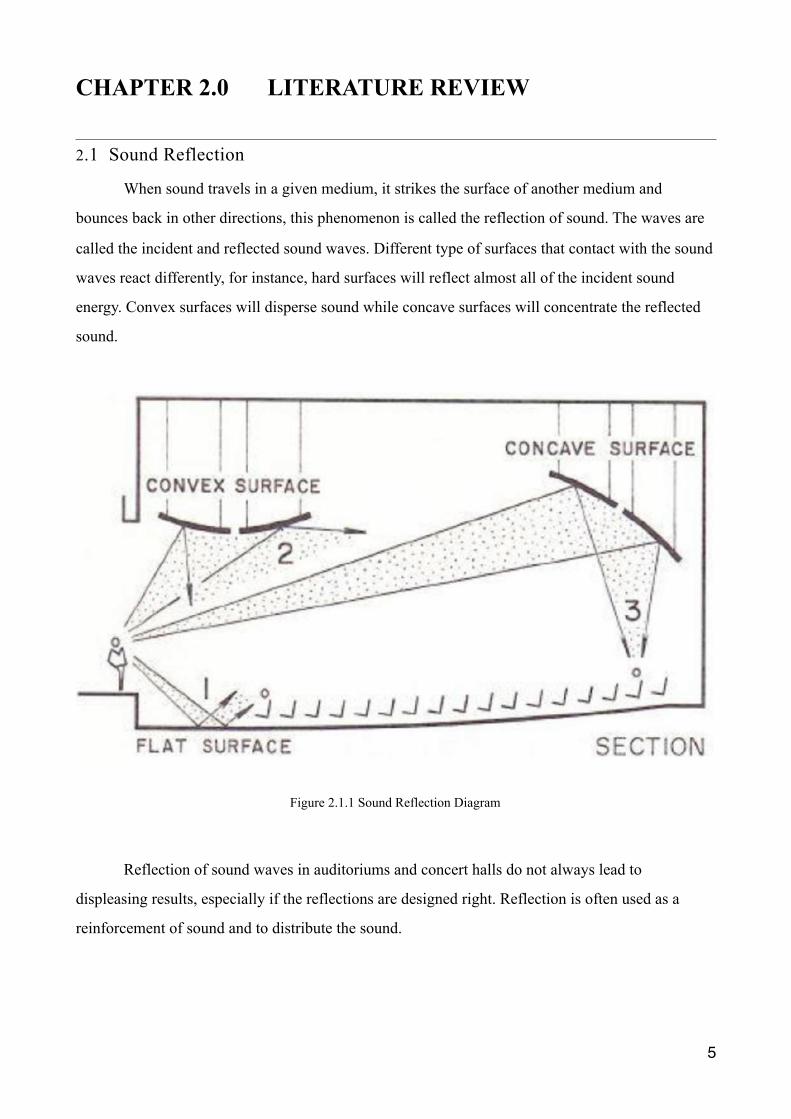
2.1 Sound Reflection
When sound travels in a given medium, it strikes the surface of another medium and
bounces back in other directions, this phenomenon is called the reflection of sound. The waves are
called the incident and reflected sound waves. Different type of surfaces that contact with the sound
waves react differently, for instance, hard surfaces will reflect almost all of the incident sound
energy. Convex surfaces will disperse sound while concave surfaces will concentrate the reflected
sound.
Reflection of sound waves in auditoriums and concert halls do not always lead to
displeasing results, especially if the reflections are designed right. Reflection is often used as a
reinforcement of sound and to distribute the sound.
�5
Figure 2.1.1 Sound Reflection Diagram

2.2 Sound Absorption Coefficient
The absorption coefficient is a common quantity used for measuring the amount of sound
absorption of a material and is known to be the function of the frequency of the incident wave. It is
defined as the ratio of energy absorbed by a material to the energy incident upon its surface.
Absorption coefficient, α = Sound Energy Absorbed
Incident Sound Energy
�6
Figure 2.1.2 /useful ceiling reflections for flat ceiling.
Figure 2.1.3 Useful ceiling reflection for layered ceiling.

A perfect absorber has an absorption coefficient of 1.0, for instance, an open window. Sound
absorption coefficient performed differently with different type of building materials.
2.2.1 Types of Sound Absorber
1. Porous absorbers
Porous sound absorbers react to the materials in its network of interconnected pores and the
thermal interaction cause sound energy to be dissipated and converted to heat. The absorption of
porous material is most effective at frequencies above 1 kHz.
2. Cavity absorbers
Helmholtz Resonators or cavity absorbers are perforated structures containing very small
pores and connected by a narrow opening to the surrounding. It can absorb maximum sound energy
in a narrow region of a low frequency band.
�7
Figure 2.2.1.1 Examples of porous absorbers.
Figure 2.2.1.2 Examples of Cavity Absorbers.

2.3 Direct and Indirect Sound Path
The sound emitted from the sound source that reaches the audience without any reflection is
called direct sound; the sound that reaches the audience after one or more reflections is called
indirect sound. When the audience in a hall or acoustic room is seated closely with the main stage,
they tend to receive direct sound more whereas the audience seated further away often receives
indirect or reflected sound.
Indirect sound have widely varying reflective properties compared to direct sound as they
reflect on different surfaces or distances in the hall/acoustic room. Reflected sound beneficially
reinforces the direct sound if the time delay between them is relatively short, that is a maximum of
30msec.
Time Delay = 𝑅1+𝑅2 –𝐷
0.34
�8
Figure 2.3.1 Reflection of direct sound path.

2.4 Reverberation Time
Reverberation is the continuing presence of audible sound after the producing of sound has
been stopped. It is affected by the reflective properties of the surfaces in the hall or acoustic room. A
reflective surface will cause the sound to die away in a longer period of time while an absorbance
surface will cause the sound to die away quickly.
�9
Figure 2.3.2 Sound reflector diagram.
Figure 2.4.1 Reverberation time diagram.

If the source of sound stops, in a result, the reverberant sound level decays (loses sound
pressure level over some time). Besides, the time it takes for sound pressure level to decay will
affect the acoustical quality of the space.
Reverberation time is the time for the sound pressure level in a room to decrease by 60dB
from its original level after the sound is stopped. It is dependent upon a few factors, the volume of
the enclosure (distance), total surface area, and the absorption coefficients of the surfaces.
�10
Figure 2.4.2 Reverberation time diagram.

CHAPTER 3.0 SITE INFORMATION
3.1 Chosen Site Information
The Majlis Bandaraya Shah Alam auditorium was built in the early 90s and could
accommodate approximately 1000 people. During the early years, the auditorium was mainly used
for formal events where foreign diplomats were usually involved hence there were several
translation rooms overlooking the auditorium from above. It was also the favoured venue to
perform for the Malaysian Philharmonic Orchestra before the Petronas Filharmonik Hall was built
in 1998. A season of the Malaysian TV reality show “Maharaja Lawak Mega” was aired live from
the auditorium. The typical programmes in the auditorium are live singing performances and
occasionally some formal speeches. The in-house sound system has been out of order since 2014
and there were no restoration efforts scheduled due to lack of funding and the outdated nature of the
sound systems.
�11
Figure 3.1.1 Live concert performances

�12
Figure 3.1.2 Live concert performances.
Figure 3.1.3 Formal speech event.

�13
Figure 3.1.4 Perspectives of the auditorium hall.

3.2 Auditorium’s Drawings
�14
Figure 3.2.1 Lower Ground Floor Plan.

�15
Figure 3.2.2 Upper Ground Floor Plan.

�16
Figure 3.2.3 Longitudinal Section.

3.3 Site Zoning
s
�17
Figure 3.3.1 Lower level sound intensity.
Figure 3.3.2 Upper level sound intensity.

CHAPTER 4.0 EXISTING SOUND SOURCES
4.1 Sound Surround System
The MBSA Auditorium Hall uses the 5.1 surround sound system since the completion of the
hall in the early 90s. This surround sound system often indicates to system of a high standard
quality, as ‘true’ surround sound. The system consists of five speakers and a subwoofer; a powered
power designed to produce bass tones and low frequency tones. As for the main five speakers, two
of them are on the front left and right, and two are at the rear left and right, and lastly the center
quality speaker. The center speaker system is larger and more versatile, where it consists of more
individual speaker cones.
4.1.1 Equipment Location
�18
Figure 4.1.1 Ground Floor Plan

4.1.2 Equipment Specification
�19
Figure 4.1.2 First Floor Floor Plan

4.2 Existing Noise Source and Noise Control
4.2.1 External Noise
In the MBSA Auditorium Hall, the absence of external noise source could be
detected due to the existence of soundproof system and the location of the building, which is
further away from other surrounding buildings. It is also enabled by the spaces placed
around the auditorium hall, which forms a buffer zone, enhancing the desire sound in the
auditorium.
�20

�21
Figure 4.2.1.1 External noise source location and buffer zone indication

4.2.2 Internal Noise
The internal noise source locates around the auditorium hall, which is the corridor
direct towards the entrance as well as the backstage area. This noise source exists only
during the presents of events. It is reduced by the application of soundproof wall around the
auditorium space. Internal noise source also comes from the ceiling air grills installed
throughout the lower floor ceiling for ventilation and air conditioning purposes. It is avoided
by the management group through activating the ventilation system 1 to 2 hours ahead of the
event at low-level to prevent the noise from degrading the standard of performance.
�22
Figure 4.2.2.1 Internal noise sources’ location

4.2.3 Equipment Specification
�23

CHAPTER 5.0 MATERIALS AND PROPERTIES
�24
Figure 5.1 Materials’ location

�25
Figure 5.2 Materials’ location

Material Absorption Coefficient
5.1 Floor
Wood flooring is any product manufactured from timber that is designed for use as flooring,
either structural or aesthetic purpose. This type of flooring is generally used for special purpose
floor, like the auditorium due to its reflective nature.
Wood is a common choice as a flooring material and can come in various styles. The type of
wood flooring used in MBSA Auditorium is solid hardwood flooring.
�26

Solid hardwood floors are made of planks milled from a single piece of timber. Solid wood
floors have a thicker wear surface and can be sanded and finished more times than an engineered
wood floor.
A sloping floor is desirable especially for large halls, it helps in improving the sight lines of
the audience. Moreover, when sitting on a sloping floor, the listeners receives more direct sound
compared to when it is on a flat floor.
Generally, the slope of an auditorium floor should not be less than 8° and for safety purposes
the slope should not exceed about 35°.
�27
Figure 5.1.1 Materials used at different location.

5.2 Wall
5.2 Wall
The walls of the auditorium are generally covered with sound absorbent materials like
compressed fibreboard or draperies, which is to reduce reverberation. These materials reduce the
formation of echoes by absorbing sound waves.
The acoustic material typically visible to the audience is devoted to a different task
altogether: absorbing or dampening the sound waves that emanate from stage in front of them. Most
of the time, the idea behind the application of these materials is to keep the sounds from echoing off
of the walls of an enclosed space, a phenomenon that, if left unchecked, would likely produce a
very aurally confusing experience for the audience.
The type of material used on the walls in MBSA Auditorium is sound absorbing foam. It is
layered on with wooden panels of different widths that act as a diffuser, which is to match the high
and low frequencies of sound.
�28
Figure 5.1.2 Floor slope diagram.

5.3 Ceiling
The ceiling of MBSA has a slanting profile to reflect the sound. It is suspended plaster,
providing different planes that reflect varying wavelengths of sound. Constructed on metal lath, the
ceiling is plastered thickly to resist panel vibration. Also with the thick mass of plaster and a proper
suspension system, it will permit the external noise from being transferred inside. A high volume of
the auditorium hall is recommended for good acoustic qualities.
�29
Figure 5.2.1 Photo of absorptive wall.
Figure 5.3.1 Photo of auditorium’s ceiling.
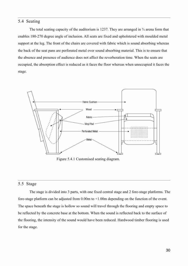
5.4 Seating
The total seating capacity of the auditorium is 1237. They are arranged in ¾ arena form that
enables 180-270 degree angle of inclusion. All seats are fixed and upholstered with moulded metal
support at the leg. The front of the chairs are covered with fabric which is sound absorbing whereas
the back of the seat pans are perforated metal over sound absorbing material. This is to ensure that
the absence and presence of audience does not affect the reverberation time. When the seats are
occupied, the absorption effect is reduced as it faces the floor whereas when unoccupied it faces the
stage.
5.5 Stage
The stage is divided into 3 parts, with one fixed central stage and 2 fore-stage platforms. The
fore-stage platform can be adjusted from 0.00m to +1.00m depending on the function of the event.
The space beneath the stage is hollow so sound will travel through the flooring and empty space to
be reflected by the concrete base at the bottom. When the sound is reflected back to the surface of
the flooring, the intensity of the sound would have been reduced. Hardwood timber flooring is used
for the stage.
�30
Figure 5.4.1 Customised seating diagram.

5.6 Openings
There are total of 7 fire exit doors in the auditorium. 4 doors are located at ground floor and
the rest at second floor. The wooden doors are acoustic and framed with steel. All of the doors have
thick curtain hung against them. The curtains act as sound absorber so that when the door is opened,
the sound will not escape from the hall. It also covers the reflective surface of the door.
5.7 Balcony
There are two balconies on each side of the wing. The balconies have fixed seats for the VIP
and carpeted flooring. Plasterboard is used for the ceiling. The railings protecting the audience from
falling off from the balcony are wooden bars and thick clear acrylic panels. The panels are made
thick to resist panel vibration.
�31
Figure 5.5.1 Perspective of stage.

CHAPTER 6.0 SITE ACOUSTICAL ANALYSIS
6.1 Incident Sound
�32
Audience sitting at the front row receives higher intensity of direct sound from the sound source compared to other positions in the hall.
Audience sitting at the middle row will receive relatively lower sound intensity as it is further from the sound source.
The intensity of sound decreases as the distance from the sound source increases. Therefore, audience sits at the upper level receives the lowest intensity of direct sound.
Audience at underside of the deep balcony are in the potential sound shadow area, where direct sound could not reach. Sound reflection and diffraction are used to supplement for the condition.
Figure 6.1.1 Incident sound diagram.

6.2 Sound Reflection and Absorption
6.2.1 Properly-tilted Ceiling
Back rows of audience seatings are shaded with lower ceiling resulting from balcony
seatings at upper level. Slanted ceiling reflects sound and distribute it to deeper rows of seatings to
optimise the acoustic experience.
�33
Figure 6.2.1.1 Sound Reflection Analysis of Rear of Auditorium.
Figure 6.2.1.2 Sound Reflection Analysis of Ceiling of Auditorium.

Properly tilted ceilings ensure the sound emitted from the sound source travel to the
audience by sound reflection and directs the sound in specific directions. As a result, reflection of
sound through the tilted ceiling is able to optimise and distribute sound throughout the whole
auditorium.
�34
Figure 6.2.1.3 Sound Reflection Analysis of In House Speakers.

6.2.2 Speakers
1. In house speakers
House speakers placed at stage acting as the main source of sound, directing all
incident sound towards audience, whereas sound woofers placed around audience provides
better hearing experience.
�35
Figure 6.2.2.1 Sound Reflection Analysis of External Speakers.

2. External Speakers
Two main speakers are placed on both sides of stage, where diamond shaped stage allows all
sound to be reflected towards audience, whereas monitor speakers direct sound to performers.
�36
Figure 6.2.2.2 Sound Reflection Analysis without Speakers

6.3 Sound Diffusion / Dispersion
By enhancing the sound emitted from sound source through the design and material of
surfaces it selves, usage of external amplifier is at zero. At lower level of auditorium, seatings at
centre row are removed due to the lack of reflected sound or weak reflected sound arriving at that
position, as two straight walls are placed parallel to each other, perpendicular to sound source.
Control Room with Angular Surfaces
Above the box seatings is an angular surface that reflects the sound emitted from sound
source. Sides of the surface are made up of wooden panels, in a result, the audience receives
adequate amount of reflected sound from the surrounding area.
�37
Figure 6.3.1 Sound Reflection Analysis of Angular Surfaces.

Acoustic Shadow
The deep balcony created a potential acoustical shadow at the seats underneath the
balcony. Besides that, the application of absorptive wall at the end of the auditorium hall
causes the possible reflected sound waves to lose its energy, therefore transmitting a
relatively low intensity reflected sound towards the area below, forming an acoustic shadow
area.
�38
Figure 6.3.2 Acoustic Shadow
Figure 6.3.3 Interior Side View Figure 6.3.4 Removal of Seats

Wooden Slat Acoustic Diffuser
The wooden slats acoustic diffuser applied on the wall functions with the same theory as
cavity absorber. When sound waves travel into the gap space, certain percentage of it is absorbed by
the absorption material behind the slats, the reduced sound energy is then reflected for multiple
times in the space, further decreasing the energy of sound.
�39
Figure 6.3.5 Sound Reflection in Cavity Wall.

6.4 Reverberation Time Calculation
Absorption of surface = Surface area (m²) x Absorption coefficient of surface (500Hz)
As (Ceiling) = 630.7m² x 0.1 = 63.07 m²sabins
As (Seating) = 1.2m² x 1237 x 0.56 = 831.26 m²sabins
As (Curtain) = 45.5m² x 0.35 = 15.93 m²sabins
Wall
As (Wood Slat Acoustic Diffuser) = 102.3m² x 0.42 = 42.97 m²sabins
As (Wood Panel Sound Diffuser) = 232.66m² x 0.17 = 39.55 m²sabins
As (Concrete) = 697.33m² x 0.02 = 13.95 m²sabins
Floor
As (Carpet) = 352.72m² x 0.44 = 49.38 m²sabins
As (Wooden) = 281.12m² x 0.2 = 56.22 m²sabins
As (Door) = 65m² x 0.14 = 9.1 m²sabins
Balcony
As (Thick Clear Acrylic Panels) = 32.36m² x 0.7 = 22.65 m²sabins
As (Wood Railing) = 16.95m² x 0.1 = 1.7 m²sabins
Openings
As (Deep Balcony) = 110.4² x 0.5 = 55.2 m²sabins
As (Ventilation Grills) = 2.97m² x 0.15 = 0.45 m²sabins
�40

Total Absorption = 63.07 + 831.26 + 15.93 + 42.97 + 39.55 + 13.95 + 49.38 + 56.22 + 9.1 + 22.65 + 1.7 + 55.2 + 0.45 = 1201.43 (m²sabins)
Reverberation Time = 0.16 x Volume of the room ÷ Total absorption
RT = 0.16 x 10200m³ ÷ 1201.43m²sabins = 1.36s
�41

CHAPTER 7.0 ISSUE AND RECOMMENDATION
7.1 Issues
One of the concerns that could be seen in MBSA auditorium hall is the absence of concave
surface that has the potential to form concentration of sound waves especially for the back rows.
This will result in non-uniform distribution of sound waves, causing a different acoustic experience
for the audience.
�42
Figure 7.1.1 Sound Reflection of Auditorium.

Another issue that is detected in the hall is the acoustic shadow area that is located below the
balcony due to the depth as well as the absorptive wall behind. This could affect the amount of
sound received by audience, especially the last seating row.
�43
Figure 7.1.2 Sound Shadow Issue

7.2 Recommendations
Solution 01
To achieve desired sound throughout the whole auditorium and to ensure the satisfaction of
the acoustic experience, ceiling is recommend to tilt or orientate in a more concave-like shape.
Concentrated sound can be produced and distributed uniformly once the sound is reflected.
�44
Figure 7.2.1 Concave Ceiling Suggestion.

Solution 02
�45
Figure 7.2.2 Ceiling Adjustment.

The initial design of the auditorium hall has a deep balcony, which then creates a potential
acoustical shadow underneath the balcony. The application of absorptive wall at the end of the
auditorium hall also causes the possible reflected sound to losses its energy, therefore transmitting a
relatively low intensity sound towards the area, forming an acoustic shadow area.
The recommended solution for the occurrence of acoustic shadow below the balcony is to escalate
the height of the floor to balcony dimension and at the same time, increase the steepness of the
tilted ceiling of the lower floor. This will ensure the reflected sound is able to be guided towards the
audience below the balcony area without decreasing the energy of the sound.
�46

CHAPTER 8.0 CONCLUSION The calculated reverberation time of 1.36s at 10200m³ volume reinforces the mixed use
nature of the Majlis Bandaraya Shah Alam auditorium. With the common programs such as live
singing performances and the occasional speech conferences, the reverberation time is neutral and
neither fully catered towards speeches nor musicals. The reverberation time of 1.36s is suitable for
live singing performances due to the presence of music that should have a relatively higher
reverberation time to reach more ‘fullness’ and at the same time, the program requires a relatively
lower reverberation time to maintain the intelligibility of the lyrics.
�47

CHAPTER 9.0 APPENDIX AND REFERENCES
�48

REFERECNES
1. https://www.acousticalsurfaces.com/acoustic_IOI/101_13.htm
2. https://www.barbourproductsearch.info/DeAmp%20Brochure-file058984.pdf
3. http://www.acoustic.ua/st/web_absorption_data_eng.pdf
4. http://mapleintegration.com/sound_ab.php
5. https://issuu.com/jacquelyntan/docs/a4_report_completed
6. https://www.engr.psu.edu/ae/thesis/portfolios/2005/sas444/Final%20Report/Acoustics.pdf
7. https://www.omicsonline.org/open-access/a-comparative-analysis-of-acoustic-material-and-
effects-on-churchauditoriums-old-and-new-churches-in-nigeria-0976-4860-1000153.php?
aid=67941
8. https://www.lifewire.com/what-is-surround-sound-audio-2640440
9. http://www.electrovoice.com/downloads.php?fam=51&title=SL%20Series&d=1
10. http://www.hifido.co.jp/KW/G0201/J/0-10/C12-68892-54803-00/
11. http://www.music-group.com/Categories/Behringer/Loudspeaker-Systems/Portable-
Speakers/B1220-PRO/p/P0284
12. https://oneroofstore.com/behringer-vp1520.html
13. https://www.bunnings.com.au/csr-edmonds-ventilation-whirly-mate-ceiling-grille_p0816657
14. https://issuu.com/priscakwan/docs/toc.docx
15. https://www.slideshare.net/mominzaki/auditorium-acoustics-33230112
�49