bsc (h) architecture degree sem 4 buidling services report final
TRANSCRIPT
SCHOOL OF ARCHITECTURE, BUILDING & DESIGN
Bachelor of Science (Honours) in Architecture
BUILDING SERVICES FOR OLD FOLKS HOME
BUILDING SERVICES (BLD 60903)
PROJECT 02 CASE STUDY AND DOCUMENTATION OF BUILDING SERVICES SYSTEM
Prepared by: Khor Hao Xiang (0318065)
Tan Jo Lynn (0318518) Teo Hong Wei (0322990) Tiong Jia Min (0323763) Yan Wai Chun (0319626) Yeoh Xiang An (0322691)
Tutor: Ar. Sateerah
Building Services (BLD 60903): August 2016 Page !1

TABLE OF CONTENT
CHAPTER 1.0 ABSTRACT 4
CHAPTER 2.0 ACKNOWLEDGEMENT 5
CHAPTER 3.0 INTRODUCTION TO BUILDING 6
CHAPTER 4.0 LITERATURE REVIEW
Section 4.1 Mechanical Ventilation System 8
Section 4.2 Air Conditioning System 12
Section 4.3 Fire Protection System 18
Section 4.4 Mechanical Transportation System 26
CHAPTER 5.0 MECHANICAL VENTILATION SYSTEM
Section 5.1 Introduction 34
Section 5.2 Spot Ventilation - Exhaust Ventilation System 35
Section 5.3 Spot Ventilation - Balance Ventilation System 37
Section 5.4 Components 39
CHAPTER 6.0 AIR CONDITIONING SYSTEM
Section 6.1 Introduction 45
Section 6.2 Ductless Heating Ventilation and Air-Conditioning (HVAC) System 46
Section 6.3 Split Air-Conditioning System 47
Section 6.4 Components 56
Building Services (BLD 60903): August 2016 Page !2

CHAPTER 7.0 FIRE PROTECTION SYSTEM
Section 7.1 Introduction 62
Section 7.2 Passive Fire Protection System 62
Section 7.3 Active Fire Protection System 69
CHAPTER 8.0 MECHANICAL TRANSPORTATION
SYSTEM
Section 8.1 Proposal 1; Schindler 330A Low Rise Hole-less Hydraulic Elevator 84
Section 8.2 Hole-less Hydraulic Elevator Components 85
Section 8.3 Proposal 2; Dumbwaiter 89
CHAPTER 9.0 CONCLUSION 90
CHAPTER 10.0 REFERENCES 91
Building Services (BLD 60903): August 2016 Page !3
1.0 ABSTRACT
The following proposals documented our research and application of services planned in the
chosen old folks home design. The service systems that has been include are mechanical ventilation
system, air conditioning system, fire protection system and mechanical transportation system.
Through the studies and research, we have gained understanding of the function, purpose and
operation of the service components which we will incorporate them in future projects.
The studies and applications of building services is recorded and translated via analysis with
explanation on how each of the selected system function. Each of the system would then be
compared with UBBL Law requirement in order to obtain clearer knowledge of the regulation
implemented on the different services.
Building Services (BLD 60903): August 2016 Page !4
2.0 ACKNOWLEDGEMENT
To begin with, we would like to express our greatest gratitude to Ar Sateerah, our beloved tutor on guiding us to have a better understanding towards the each systems, giving us
suggestions for system proposal and the correct way to apply the knowledge into the selected Elderly Centre design. Nonetheless, she have been a strong motivator on pushing us to explore
deeper into our research area which gives us the positive attitude to learn more on Building Services.
In conclusion, we are able to learn the importance on services in a building, how they
contributed to the building’s safety and comfort, while taking into considerations that are needed while designing a building, which will be crucial and beneficial for our career ahead.
Building Services (BLD 60903): August 2016 Page !5
3.0 INTRODUCTION
The selected old folks home was done by one of our group member, Yan Wai Chun
(0319626). It is designed based on the concept of an elderly community centre. The given site is
located in Taman Kanagapuram, Petaling Jaya, an old residential area.
The building is arranged in a clustered form. It consists of two storeys, three main block and
13 rooms, surrounding an internal courtyard that function as a gardening area for the elderlies. It
was built-up in a total range of approximately 800 sqm. Other than functioning as a community
centre, it allows the elderlies to farm and plant for further trading purposes as well as to supply
goods to the existing cafe.
To ensure the safety and comfort of elderlies, the building is designed with completed
services of mechanical ventilation, air conditioning system, fire protection and mechanical
transportation system.
Building Services (BLD 60903): August 2016 Page !6
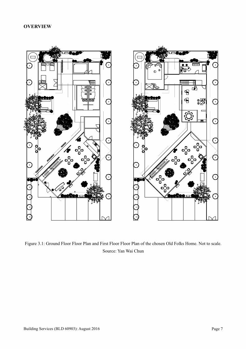
OVERVIEW
Figure 3.1: Ground Floor Floor Plan and First Floor Floor Plan of the chosen Old Folks Home. Not to scale. Source: Yan Wai Chun
Building Services (BLD 60903): August 2016 Page !7
CHAPTER 4.0 LITERATURE REVIEW
4.1 Mechanical Ventilation System
Mechanical ventilation in a building is to promote fresh air into building and remove any latent heat
by means of mechanical devices to control the indoor air quality, odours, humidity and
contaminants accumulated inside a building. The main function of mechanical ventilation is to
expel stale air containing water vapour, carbon dioxide, airborne chemicals and other pollutants and
replace by drawing in air from the outside, presumably contains less pollutants and water vapour
and also circulate the air throughout the building.
Mechanical ventilation is important as:
1. It controls indoor air humidity and ensure comfort.
2. It prevent heat concentration from machinery, lighting and people.
3. It preserves the oxygen content and removes carbon dioxide.
4. It prevent condensation.
5. It disperse the concentration of bacteria.
6. It helps in dilution and disposal of contaminants such as smoke, dust gases and body odours.
7. It provides constant fresh air.
8. It act as an alternative to natural ventilation.
There are three types of ventilation:
4.1.1 Supply Ventilation System
In supply ventilation system, outside air is provided by mechanical means in order to
maintain positive air pressure and then extracted naturally. This system is usually used in boiler
plants and factories.
Building Services (BLD 60903): August 2016 Page !8
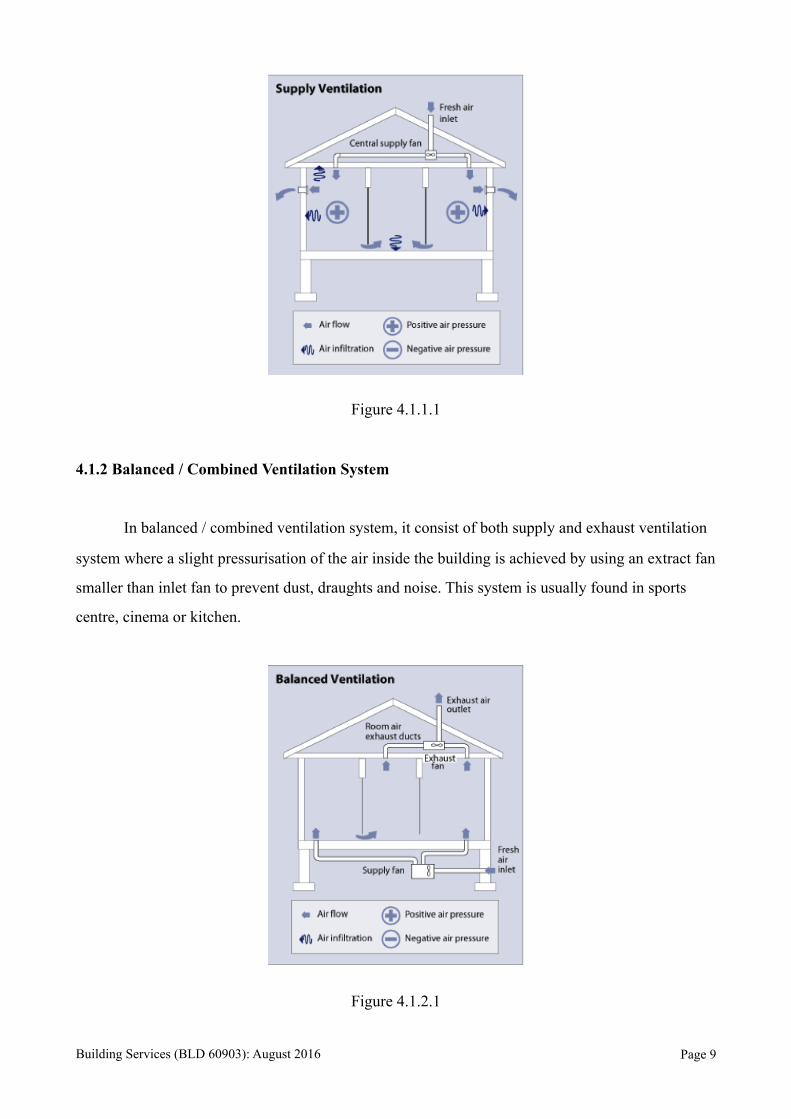
Figure 4.1.1.1
4.1.2 Balanced / Combined Ventilation System
In balanced / combined ventilation system, it consist of both supply and exhaust ventilation
system where a slight pressurisation of the air inside the building is achieved by using an extract fan
smaller than inlet fan to prevent dust, draughts and noise. This system is usually found in sports
centre, cinema or kitchen.
Figure 4.1.2.1
Building Services (BLD 60903): August 2016 Page !9
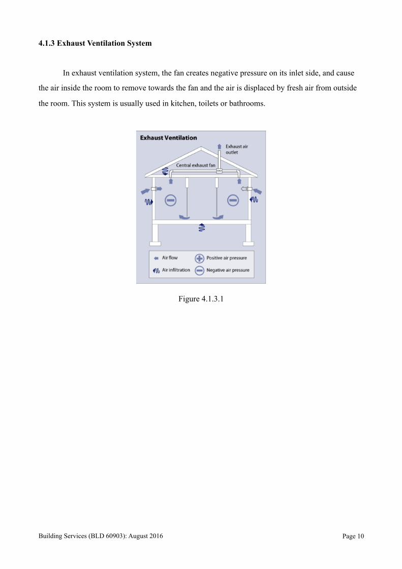
4.1.3 Exhaust Ventilation System
In exhaust ventilation system, the fan creates negative pressure on its inlet side, and cause
the air inside the room to remove towards the fan and the air is displaced by fresh air from outside
the room. This system is usually used in kitchen, toilets or bathrooms.
Figure 4.1.3.1
Building Services (BLD 60903): August 2016 Page !10

4.1.4 Comparisons of Supply, Balanced / Combined, and Exhaust Ventilation Systems
Ventilation System Advantages Disadvantages
Supply Ventilation System
1. Simple and not costly to install. 2. Allows better control of air entering the house. 3. Minimise outdoor pollutants in the internal living space as incoming air can be filtered.
1. Can cause moisture problem in the cold area.
2. Does not Remove moist from incoming air.
Balanced / Combined Ventilation System
1. No pressurisation in internal spaces.
2. Allows the use of filters to remove dust and water vapour from outside air.
3. Appropriate in all climates. 4. Quantity of stale air and
fresh air extracted are the same.
1. Expensive Installation as it requires two sets of ductworks and fans.
Exhaust Ventilation System
1. Appropriate in cold climates.
2. Prevent moisture into the internal spaces.
3. Simple and easy to install.
1. Can draw in pollutants into internal spaces.
2. Cause noises.
Building Services (BLD 60903): August 2016 Page !11
4.2 Air Conditioning System
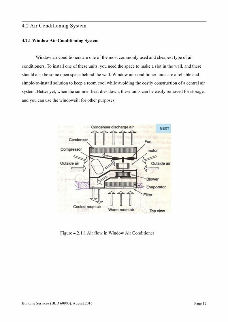
4.2.1 Window Air-Conditioning System
Window air conditioners are one of the most commonly used and cheapest type of air
conditioners. To install one of these units, you need the space to make a slot in the wall, and there
should also be some open space behind the wall. Window air-conditioner units are a reliable and
simple-to-install solution to keep a room cool while avoiding the costly construction of a central air
system. Better yet, when the summer heat dies down, these units can be easily removed for storage,
and you can use the windowsill for other purposes.
Figure 4.2.1.1 Air flow in Window Air Conditioner
Building Services (BLD 60903): August 2016 Page !12
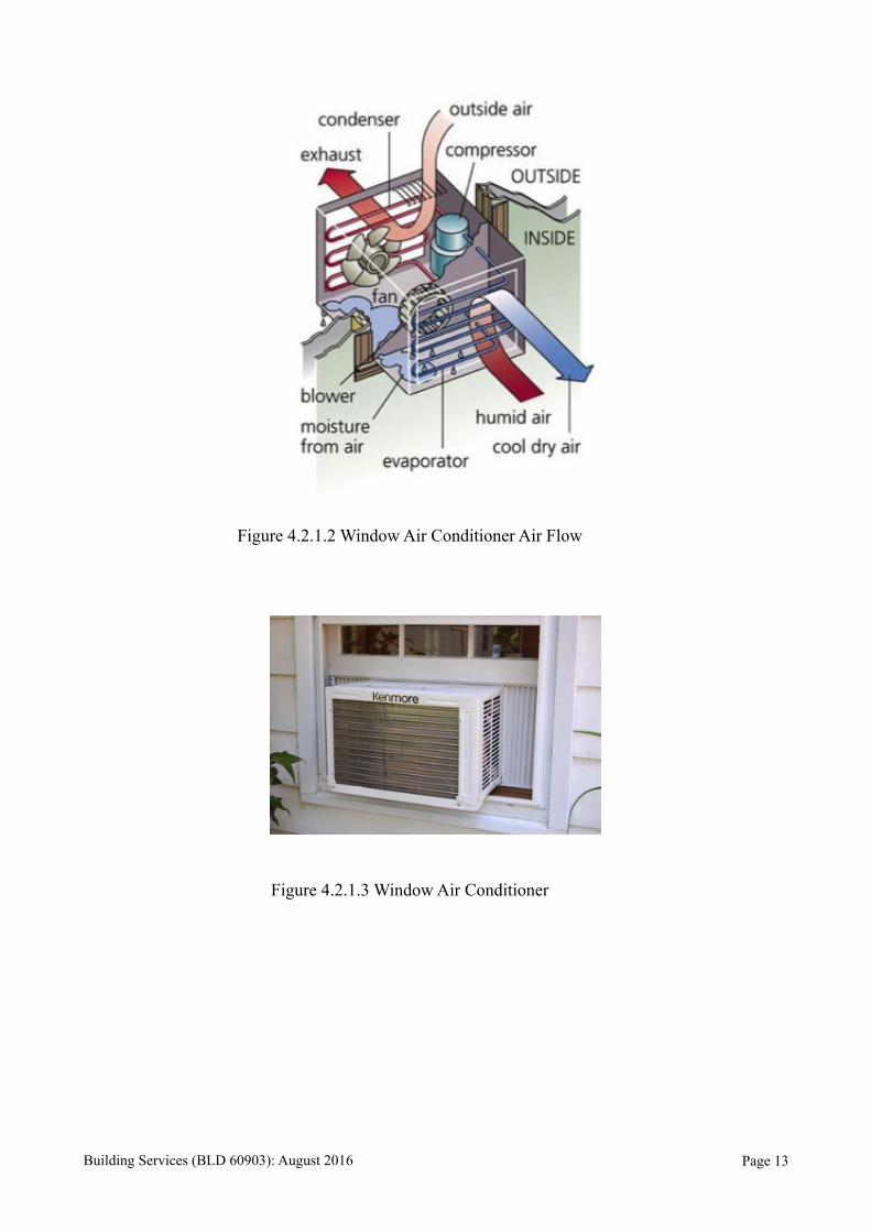
Figure 4.2.1.2 Window Air Conditioner Air Flow
Figure 4.2.1.3 Window Air Conditioner
Building Services (BLD 60903): August 2016 Page !13
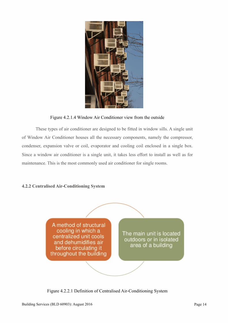
Figure 4.2.1.4 Window Air Conditioner view from the outside
These types of air conditioner are designed to be fitted in window sills. A single unit
of Window Air Conditioner houses all the necessary components, namely the compressor,
condenser, expansion valve or coil, evaporator and cooling coil enclosed in a single box.
Since a window air conditioner is a single unit, it takes less effort to install as well as for
maintenance. This is the most commonly used air conditioner for single rooms.
4.2.2 Centralised Air-Conditioning System
Figure 4.2.2.1 Definition of Centralised Air-Conditioning System
Building Services (BLD 60903): August 2016 Page !14
Centralised Air-Conditioning System are used when large buildings, hotels, theatres,
airports, shopping malls, etc are to be air conditioned completely. If the whole building is to
be air conditioned, HVAC engineers find that putting individual units in each of the rooms is
very expensive making this a better option. A central air conditioning system is comprised of
a huge compressor that has the capacity to produce hundreds of tons of air conditioning.
The window and split air conditioners are used for single rooms or small office
spaces. If the whole building is to be cooled it is not economically viable to put window or
split air conditioner in each and every room. Further, theses mall units cannot satisfactorily
cool the large halls, auditoriums, receptions areas etc. Central air conditioner unit is an
energy moving or converted machines that are designed to cool or heat the entire house. It
does not create heat or cool. It just removes heat from one area, where it is undesirable, to an
area where it is less significant.
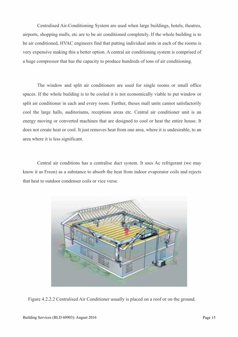
Central air conditions has a centralise duct system. It uses Ac refrigerant (we may
know it as Freon) as a substance to absorb the heat from indoor evaporator coils and rejects
that heat to outdoor condenser coils or vice verse.
Figure 4.2.2.2 Centralised Air Conditioner usually is placed on a roof or on the ground.
Building Services (BLD 60903): August 2016 Page !15
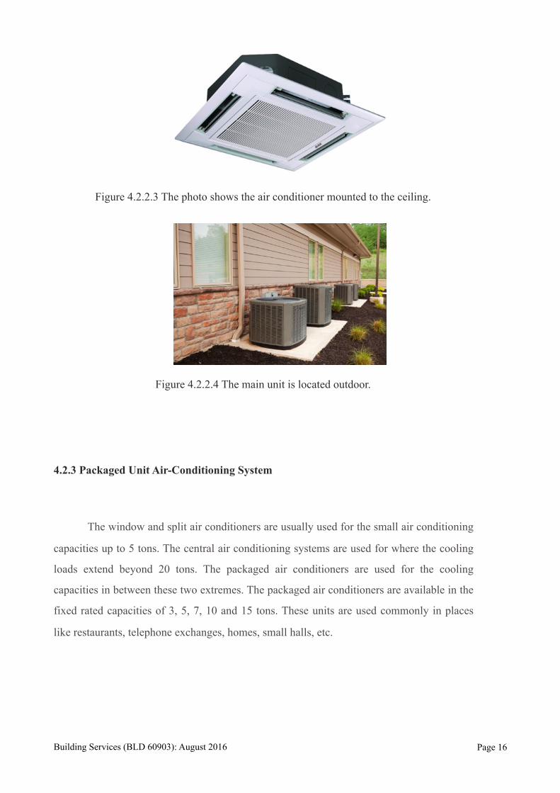
Figure 4.2.2.3 The photo shows the air conditioner mounted to the ceiling.
Figure 4.2.2.4 The main unit is located outdoor.
4.2.3 Packaged Unit Air-Conditioning System
The window and split air conditioners are usually used for the small air conditioning
capacities up to 5 tons. The central air conditioning systems are used for where the cooling
loads extend beyond 20 tons. The packaged air conditioners are used for the cooling
capacities in between these two extremes. The packaged air conditioners are available in the
fixed rated capacities of 3, 5, 7, 10 and 15 tons. These units are used commonly in places
like restaurants, telephone exchanges, homes, small halls, etc.
Building Services (BLD 60903): August 2016 Page !16
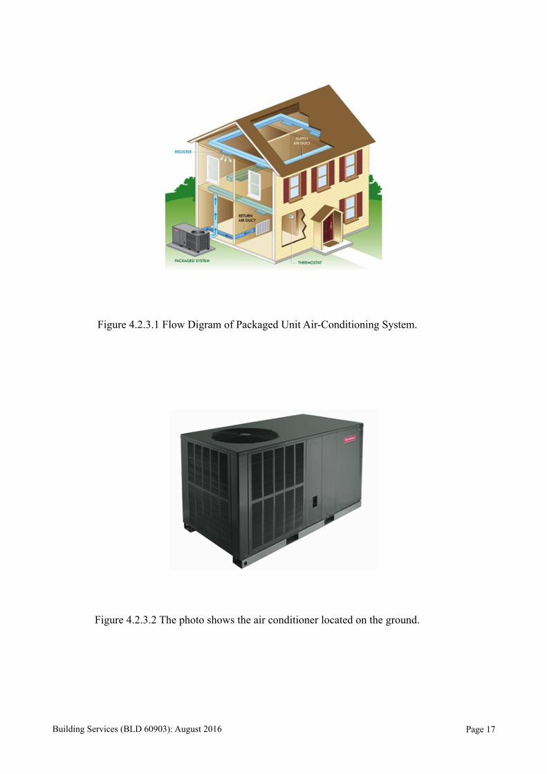
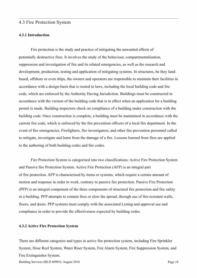
Figure 4.2.3.1 Flow Digram of Packaged Unit Air-Conditioning System.
Figure 4.2.3.2 The photo shows the air conditioner located on the ground.
Building Services (BLD 60903): August 2016 Page !17
4.3 Fire Protection System
4.3.1 Introduction
Fire protection is the study and practice of mitigating the unwanted effects of
potentially destructive fires. It involves the study of the behaviour, compartmentalisation,
suppression and investigation of fire and its related emergencies, as well as the research and
development, production, testing and application of mitigating systems. In structures, be they land-
based, offshore or even ships, the owners and operators are responsible to maintain their facilities in
accordance with a design-basis that is rooted in laws, including the local building code and fire
code, which are enforced by the Authority Having Jurisdiction. Buildings must be constructed in
accordance with the version of the building code that is in effect when an application for a building
permit is made. Building inspectors check on compliance of a building under construction with the
building code. Once construction is complete, a building must be maintained in accordance with the
current fire code, which is enforced by the fire prevention officers of a local fire department. In the
event of fire emergencies, Firefighters, fire investigators, and other fire prevention personnel called
to mitigate, investigate and learn from the damage of a fire. Lessons learned from fires are applied
to the authoring of both building codes and fire codes.
Fire Protection System is categorised into two classifications: Active Fire Protection System
and Passive fire Protection System. Active Fire Protection (AFP) is an integral part
of fire protection. AFP is characterised by items or systems, which require a certain amount of
motion and response in order to work, contrary to passive fire protection. Passive Fire Protection
(PFP) is an integral component of the three components of structural fire protection and fire safety
in a building. PFP attempts to contain fires or slow the spread, through use of fire-resistant walls,
floors, and doors. PFP systems must comply with the associated Listing and approval use and
compliance in order to provide the effectiveness expected by building codes.
4.3.2 Active Fire Protection System
There are different categories and types in active fire protection system, including Fire Sprinkler
System, Hose Reel System, Water Riser System, Fire Alarm System, Fire Suppression System, and
Fire Extinguisher System. Building Services (BLD 60903): August 2016 Page !18
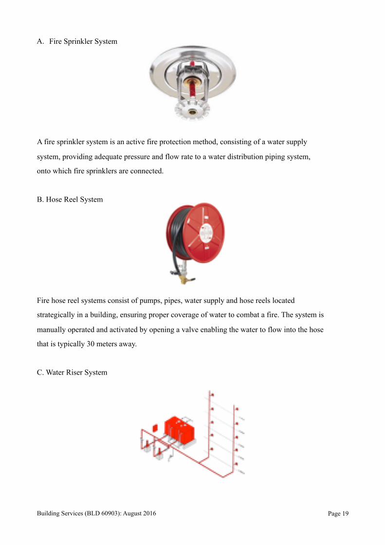
A. Fire Sprinkler System
A fire sprinkler system is an active fire protection method, consisting of a water supply
system, providing adequate pressure and flow rate to a water distribution piping system,
onto which fire sprinklers are connected.
B. Hose Reel System
Fire hose reel systems consist of pumps, pipes, water supply and hose reels located
strategically in a building, ensuring proper coverage of water to combat a fire. The system is
manually operated and activated by opening a valve enabling the water to flow into the hose
that is typically 30 meters away.
C. Water Riser System
Building Services (BLD 60903): August 2016 Page !19
Water riser system includes dry riser system and wet riser system. Dry fire main water
supply pipe installed in a building for fire-fighting purposes, fitted with inlet connections at
fire service access level and landing valves at specified points, which is normally dry but is
capable of being charged with water usually by pumping from fire and rescue service
appliances. Wet fire main water supply pipe installed in a building for fire-fighting purposes
and permanently charged with water from a pressurised supply, and fitted with landing
valves at specified points.
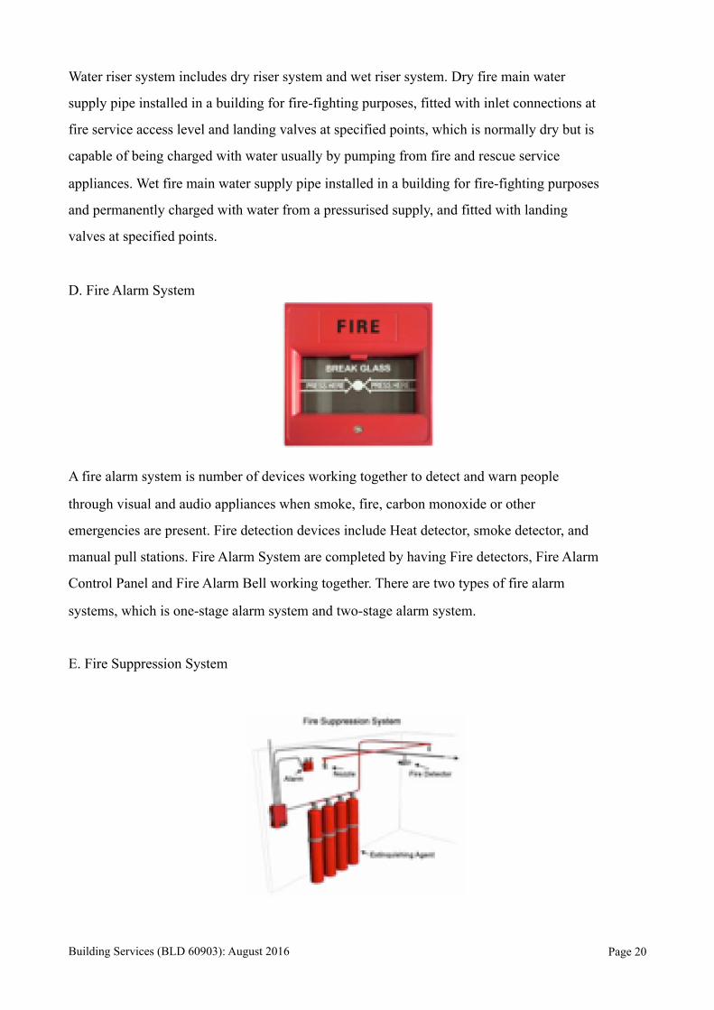
D. Fire Alarm System
A fire alarm system is number of devices working together to detect and warn people
through visual and audio appliances when smoke, fire, carbon monoxide or other
emergencies are present. Fire detection devices include Heat detector, smoke detector, and
manual pull stations. Fire Alarm System are completed by having Fire detectors, Fire Alarm
Control Panel and Fire Alarm Bell working together. There are two types of fire alarm
systems, which is one-stage alarm system and two-stage alarm system.
E. Fire Suppression System
Building Services (BLD 60903): August 2016 Page !20
Fire suppression system is used to protect special hazard or sensitive areas, like bank and
computer rooms. Fire Suppression System includes Carbon dioxide systems, dry chemical
agents and application system, and Aragonite, which are environmental friendly clean
agents.
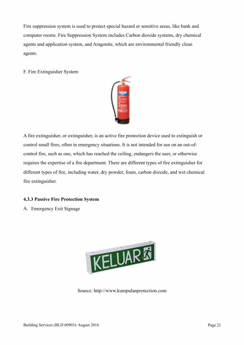
F. Fire Extinguisher System
A fire extinguisher, or extinguisher, is an active fire protection device used to extinguish or
control small fires, often in emergency situations. It is not intended for use on an out-of-
control fire, such as one, which has reached the ceiling, endangers the user, or otherwise
requires the expertise of a fire department. There are different types of fire extinguisher for
different types of fire, including water, dry powder, foam, carbon dioxide, and wet chemical
fire extinguisher.
4.3.3 Passive Fire Protection System
A. Emergency Exit Signage
Source: http://www.kumpulanprotection.com
Building Services (BLD 60903): August 2016 Page !21
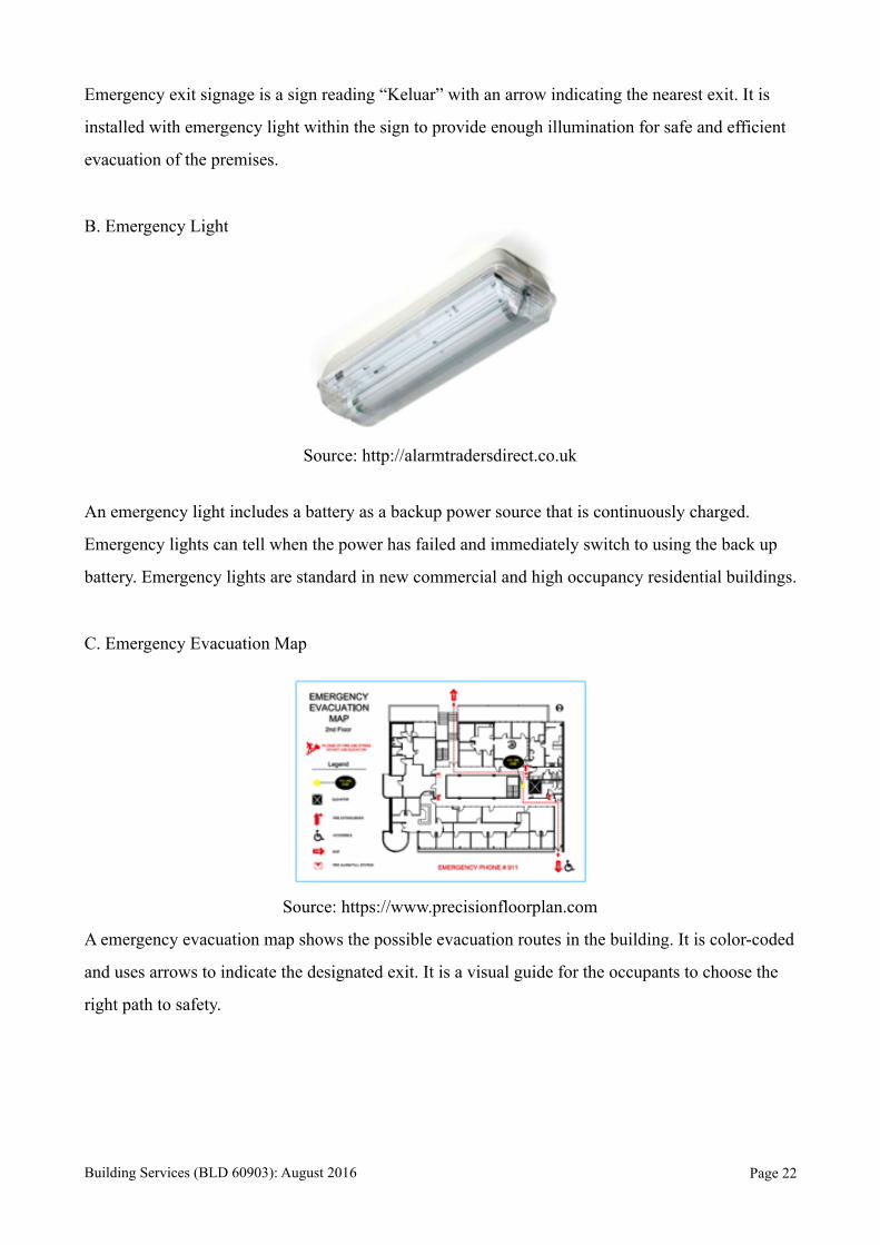
Emergency exit signage is a sign reading “Keluar” with an arrow indicating the nearest exit. It is
installed with emergency light within the sign to provide enough illumination for safe and efficient
evacuation of the premises.
B. Emergency Light
Source: http://alarmtradersdirect.co.uk
An emergency light includes a battery as a backup power source that is continuously charged.
Emergency lights can tell when the power has failed and immediately switch to using the back up
battery. Emergency lights are standard in new commercial and high occupancy residential buildings.
C. Emergency Evacuation Map
Source: https://www.precisionfloorplan.com
A emergency evacuation map shows the possible evacuation routes in the building. It is color-coded
and uses arrows to indicate the designated exit. It is a visual guide for the occupants to choose the
right path to safety.
Building Services (BLD 60903): August 2016 Page !22
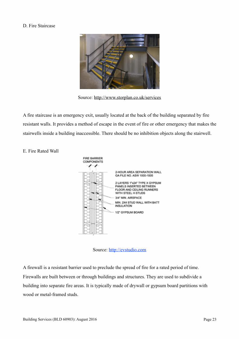
D. Fire Staircase
Source: http://www.storplan.co.uk/services
A fire staircase is an emergency exit, usually located at the back of the building separated by fire
resistant walls. It provides a method of escape in the event of fire or other emergency that makes the
stairwells inside a building inaccessible. There should be no inhibition objects along the stairwell.
E. Fire Rated Wall
Source: http://evstudio.com
A firewall is a resistant barrier used to preclude the spread of fire for a rated period of time.
Firewalls are built between or through buildings and structures. They are used to subdivide a
building into separate fire areas. It is typically made of drywall or gypsum board partitions with
wood or metal-framed studs.
Building Services (BLD 60903): August 2016 Page !23
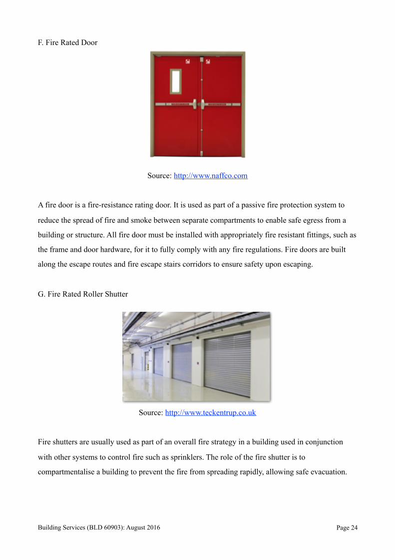
F. Fire Rated Door
Source: http://www.naffco.com
A fire door is a fire-resistance rating door. It is used as part of a passive fire protection system to
reduce the spread of fire and smoke between separate compartments to enable safe egress from a
building or structure. All fire door must be installed with appropriately fire resistant fittings, such as
the frame and door hardware, for it to fully comply with any fire regulations. Fire doors are built
along the escape routes and fire escape stairs corridors to ensure safety upon escaping.
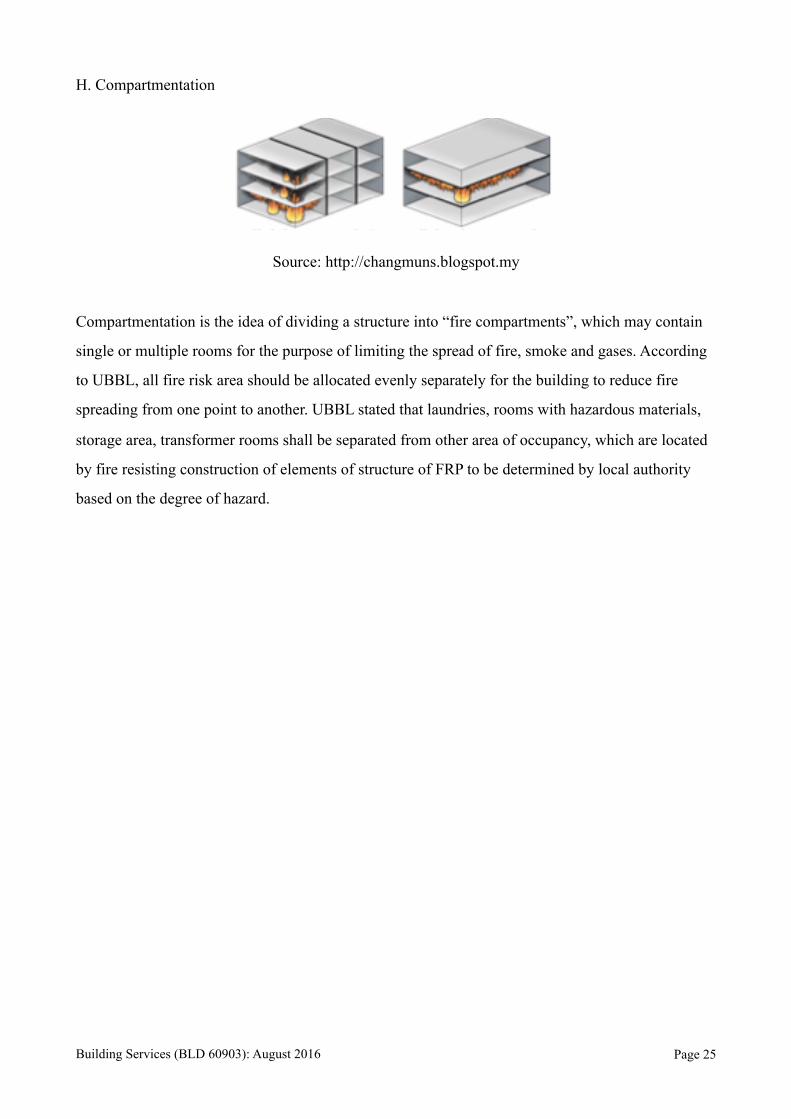
G. Fire Rated Roller Shutter
Source: http://www.teckentrup.co.uk
Fire shutters are usually used as part of an overall fire strategy in a building used in conjunction
with other systems to control fire such as sprinklers. The role of the fire shutter is to
compartmentalise a building to prevent the fire from spreading rapidly, allowing safe evacuation.
Building Services (BLD 60903): August 2016 Page !24
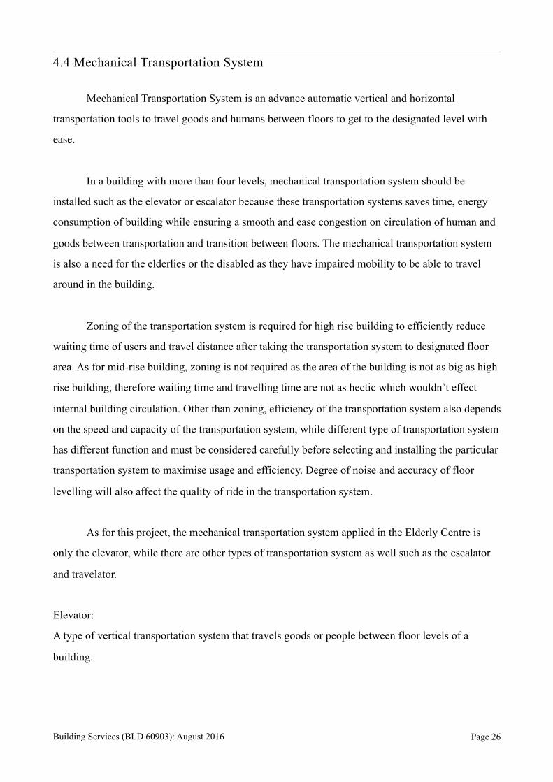
H. Compartmentation
Source: http://changmuns.blogspot.my
Compartmentation is the idea of dividing a structure into “fire compartments”, which may contain
single or multiple rooms for the purpose of limiting the spread of fire, smoke and gases. According
to UBBL, all fire risk area should be allocated evenly separately for the building to reduce fire
spreading from one point to another. UBBL stated that laundries, rooms with hazardous materials,
storage area, transformer rooms shall be separated from other area of occupancy, which are located
by fire resisting construction of elements of structure of FRP to be determined by local authority
based on the degree of hazard.
Building Services (BLD 60903): August 2016 Page !25
4.4 Mechanical Transportation System
Mechanical Transportation System is an advance automatic vertical and horizontal
transportation tools to travel goods and humans between floors to get to the designated level with
ease.
In a building with more than four levels, mechanical transportation system should be
installed such as the elevator or escalator because these transportation systems saves time, energy
consumption of building while ensuring a smooth and ease congestion on circulation of human and
goods between transportation and transition between floors. The mechanical transportation system
is also a need for the elderlies or the disabled as they have impaired mobility to be able to travel
around in the building.
Zoning of the transportation system is required for high rise building to efficiently reduce
waiting time of users and travel distance after taking the transportation system to designated floor
area. As for mid-rise building, zoning is not required as the area of the building is not as big as high
rise building, therefore waiting time and travelling time are not as hectic which wouldn’t effect
internal building circulation. Other than zoning, efficiency of the transportation system also depends
on the speed and capacity of the transportation system, while different type of transportation system
has different function and must be considered carefully before selecting and installing the particular
transportation system to maximise usage and efficiency. Degree of noise and accuracy of floor
levelling will also affect the quality of ride in the transportation system.
As for this project, the mechanical transportation system applied in the Elderly Centre is
only the elevator, while there are other types of transportation system as well such as the escalator
and travelator.
Elevator:
A type of vertical transportation system that travels goods or people between floor levels of a
building.
Building Services (BLD 60903): August 2016 Page !26
Escalator:
A moving staircase consisting of an endlessly circulating belt of steps driven by a motor, conveying
people between the floors of a public building.
Travelator:
A type of horizontal transportation system that travels goods or people on the same floor . This
system only applies on short to medium distance.
4.4.1 Elevator
An elevator is a vertical transportation system, which is an apparatus for raising and
lowering people or goods to different floors of the building. In commercial buildings, it is definite
to have vertical transportation requirements because the arrival and departure of the occupants are
usually concentrated within certain period of the day. In accordance to the By-Law 124 of UBBL
1984, an elevator shall be provided for non-residential building which exceeds 4 storeys above or
below main entrance. It is also essential in building less than 4 storeys if access for elderly or
disabled is required. There are a few factors affecting the installation of the elevators to achieve
highest usage efficiency, such as the position of the elevator, speed of the elevator as well as the
type of it. Most commonly, the elevator are to be positioned at location where it is providing the
easiest access for all building users with a maximum walking distance of 45m to the lift lobby. As
for the number of elevator is normally determined by the population of the building, type of
occupancy, numbers of floors and height as well as the initial and maintenance cost.
UBBL SECTION 124 – Lift
For all non-residential buildings exceeding 4 storeys above or below the main access level at least
one lift shall be provided.
Elevators can be classified into 4 different hoists Mechanism:
Traction Elevator Hydraulic Elevator Climbing Elevator Pneumatic Elevator
Building Services (BLD 60903): August 2016 Page !27
As for Traction Elevator, it is divided into another two divisions: Machine Room Traction
Elevator and Machine Room-less Elevator. While for Hydraulic Elevator is divided into three
divisions: Holed Hydraulic, Hole-less Hydraulic and Roped Hydraulic.
4.4.1.1 Traction elevators
Traction Elevators are the most common type of elevators. Elevator cars are pulled up by
means of rolling steel ropes over a deeply grooved pulley commonly called a sheave in the industry.
The weight of the car is balanced by a counterweight so that the motor doesn’t have to move as
much weight.
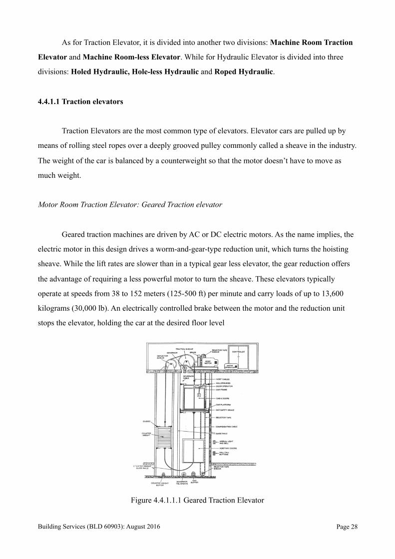
Motor Room Traction Elevator: Geared Traction elevator
Geared traction machines are driven by AC or DC electric motors. As the name implies, the
electric motor in this design drives a worm-and-gear-type reduction unit, which turns the hoisting
sheave. While the lift rates are slower than in a typical gear less elevator, the gear reduction offers
the advantage of requiring a less powerful motor to turn the sheave. These elevators typically
operate at speeds from 38 to 152 meters (125-500 ft) per minute and carry loads of up to 13,600
kilograms (30,000 lb). An electrically controlled brake between the motor and the reduction unit
stops the elevator, holding the car at the desired floor level
Figure 4.4.1.1.1 Geared Traction Elevator
Building Services (BLD 60903): August 2016 Page !28

Motor Room Traction Elevator: Gear-less Traction Elevator
Gear-less traction machines are low in speed (low-RPM), high-torque electric motors
powered by either AC or DC. The traction sheave is connected directly to the shaft of the traction
motor, and the motor rotation is transmitted directly to the traction sheave without any intermediate
gearing. Gear-less Traction Elevator can reach up to 20 m/s (4000 ft/min) in speed.
Figure 4.4.1.1.2 Gear-less Traction Elevator
Machine Room-less Traction Elevator
Machine room less elevators do not have a fixed machine room on the top of the hoist way,
instead the traction hoisting machine is installed either on the top side wall of the hoist way or on
the bottom of the hoist way. The motor is installed using a permanent magnet which "sticks" the
motor permanently and work with Variable Voltage Variable Frequency (VVVF) drive. Some of the
hoisting machines are using gear-less synchronous motors instead conventional induction motors.
This design eliminates the need of a fixed machine room and thus saves much building's space.
Almost all the traction MRL elevators are gear-less traction.
Building Services (BLD 60903): August 2016 Page !29

Figure 4.4.1.1.3
4.4.1.2 Hydraulic Elevators
Hydraulic elevators are elevators which are powered by a piston that travels inside a
cylinder. An electric motor pumps hydraulic oil into the cylinder to move the piston. The piston
smoothly lifts the elevator cab. Electrical valves control the release of the oil for a gentle descent.
Hydraulic elevators are used extensively in buildings up to five or six stories high. Sometimes, but
rarely, up to 8 stories high. These elevators, which can operate at speeds up to 61 meters (200 ft) per
minute, do not use the large overhead hoisting machinery the way geared and gear-less traction
systems do.
Holed Hydraulic Elevator
With holed hydraulic systems, the elevator car is mounted on a piston that travels inside a
cylinder. The cylinder extends into the ground to a depth equal to the height the elevator will raise.
As hydraulic fluid is pumped into the cylinder through a valve, the car rises. As the fluid returns to
the reservoir, the car descends.
Building Services (BLD 60903): August 2016 Page !30
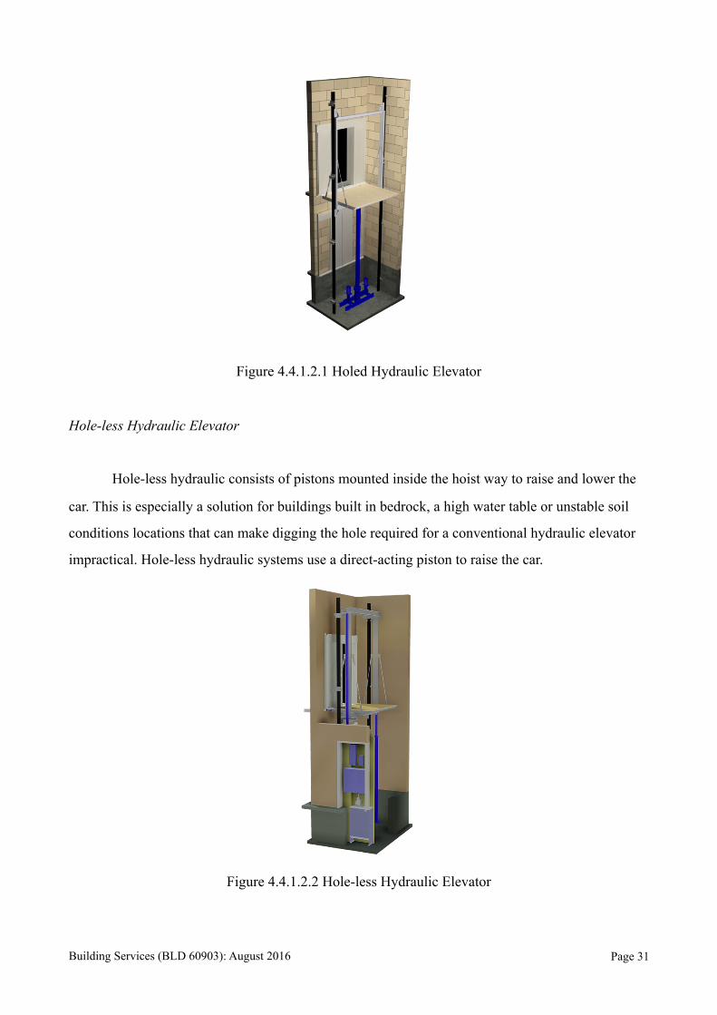
Figure 4.4.1.2.1 Holed Hydraulic Elevator
Hole-less Hydraulic Elevator
Hole-less hydraulic consists of pistons mounted inside the hoist way to raise and lower the
car. This is especially a solution for buildings built in bedrock, a high water table or unstable soil
conditions locations that can make digging the hole required for a conventional hydraulic elevator
impractical. Hole-less hydraulic systems use a direct-acting piston to raise the car.
Figure 4.4.1.2.2 Hole-less Hydraulic Elevator
Building Services (BLD 60903): August 2016 Page !31
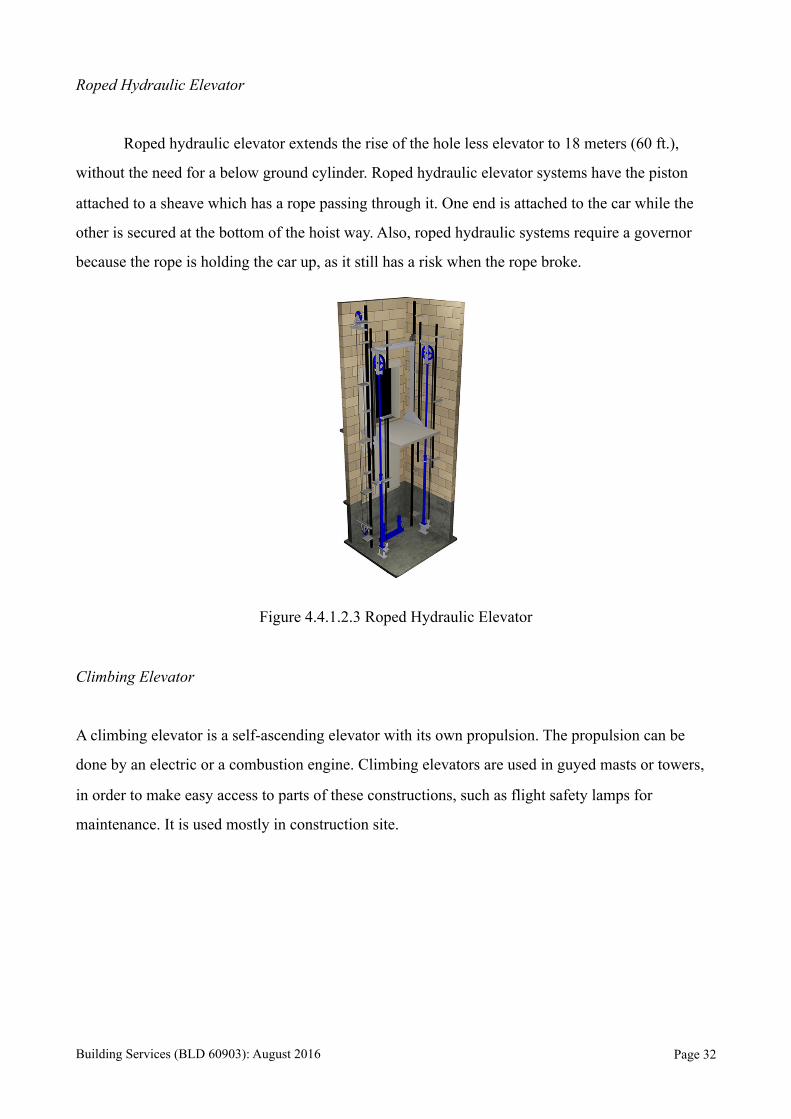
Roped Hydraulic Elevator
Roped hydraulic elevator extends the rise of the hole less elevator to 18 meters (60 ft.),
without the need for a below ground cylinder. Roped hydraulic elevator systems have the piston
attached to a sheave which has a rope passing through it. One end is attached to the car while the
other is secured at the bottom of the hoist way. Also, roped hydraulic systems require a governor
because the rope is holding the car up, as it still has a risk when the rope broke.
Figure 4.4.1.2.3 Roped Hydraulic Elevator
Climbing Elevator
A climbing elevator is a self-ascending elevator with its own propulsion. The propulsion can be
done by an electric or a combustion engine. Climbing elevators are used in guyed masts or towers,
in order to make easy access to parts of these constructions, such as flight safety lamps for
maintenance. It is used mostly in construction site.
Building Services (BLD 60903): August 2016 Page !32
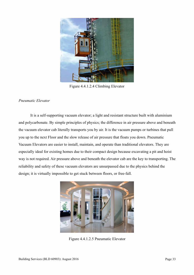
Figure 4.4.1.2.4 Climbing Elevator
Pneumatic Elevator
It is a self-supporting vacuum elevator; a light and resistant structure built with aluminium
and polycarbonate. By simple principles of physics; the difference in air pressure above and beneath
the vacuum elevator cab literally transports you by air. It is the vacuum pumps or turbines that pull
you up to the next Floor and the slow release of air pressure that floats you down. Pneumatic
Vacuum Elevators are easier to install, maintain, and operate than traditional elevators. They are
especially ideal for existing homes due to their compact design because excavating a pit and hoist
way is not required. Air pressure above and beneath the elevator cab are the key to transporting. The
reliability and safety of these vacuum elevators are unsurpassed due to the physics behind the
design; it is virtually impossible to get stuck between floors, or free-fall.
Figure 4.4.1.2.5 Pneumatic Elevator
Building Services (BLD 60903): August 2016 Page !33
CHAPTER 5.0 MECHANICAL VENTILATION SYSTEM
5.1 Introduction
The building chosen is a community centre of 2 floors, which consists of individual rooms
that are organised and clustered into 3 units to serve different purposes. Due to its spatial planning,
having separated room units, each of members has their own ventilation system installed. The
climate condition of the site caused the inlet and outlet of natural ventilation to be restricted.
Therefore, mechanical ventilation system has an important role in keeping the interior atmosphere
of the building comfortable for the user.
Types of mechanical ventilation system applied consists of below:
Exhaust Ventilation System
a. Exhaust air grille / fan
b. Elevator Shaft Exhaust Fan
Balanced Ventilation System
a. Supply and Exhaust Fan
Building Services (BLD 60903): August 2016 Page !34
5.2 Spot Ventilation - Exhaust Ventilation System
5.2.1 Exhaust air grille / fan
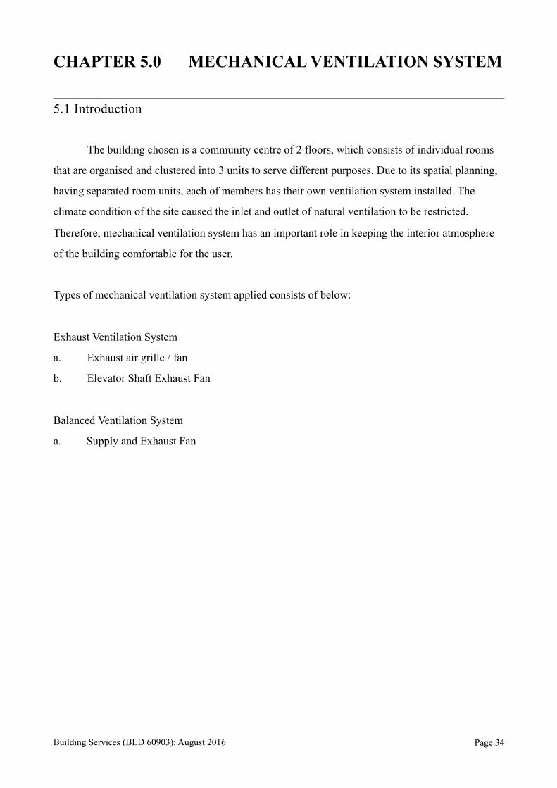
In the building chosen, it is a community centre that host 10 room units. The spaces are
arranged in clustered form but due to the climatic condition and skyline of the site, amount and
sizes of openings and fenestrations to be located are limited and are not able to operate for long.
Prior to this issue, exhaust ventilation system is applied to the room units needed to provide and
ensure quality of internal air for the user. A more complex exhaust system is used in toilet in order
to remove stale air produced.
Location:
Figure 5.2.1.1 The figure above shows the floor plan drawings of the community centre. The
highlighted area in blue is where the system is applied.
Building Services (BLD 60903): August 2016 Page !35

Utilities Room Exhaust System
The exhaust ventilation system here works by depressurising the spaces highlighted above. By
decreasing the internal air pressure until it is below the external pressure, extraction of internal air
from the space is done while allowing air infiltration through intentional vents and leaks in the
building shell.
As the air condition of the site is always hot and humid, the exhaust ventilation system aids to
remove the air out from the interior of respective spaces that are dependant on natural ventilation
for the inlet.
In the toilet, the atmosphere is generally more humid compare to other spaces due to the escape
of water vapour. Thus, the function of the ventilation system here is to eliminate the water vapour
and reduce the humidity. It is to prevent the condensation of bacteria for the safety of the user and
also to provide a pleasant environment in the space.
Whereas in spaces that are dependant on Air Conditioning System, the atmosphere is usually less
humid compare to the others. Hence, the purpose of the exhaust ventilation in this space is to
maintain the adequate humidity and the internal temperature. It is also to remove the heat generated
from the machinery out of the room through exhaust fan.
5.2.2 Elevator Shaft Exhaust Fan
In the community centre, an elevator is located to ease the accessibility of the user to the upper
floor. It connects the x to x. Due to the enclosed space form, hot and humid air are easily trapped in
the zone. Therefore, the task of the system here is to generate a wide or even circulation of air and
to ensure minimum accumulation of air in the space.
Building Services (BLD 60903): August 2016 Page !36

Location:
Figure 5.2.2.1 The figure above shows the floor plan drawings of the community centre. The
highlighted area in green is where the system is applied.
5.3 Spot Ventilation - Balanced Ventilation System
5.3.1 Supply and Exhaust fan
In the building chosen, a kitchen is placed within the Café to serve the space due to the function
of it as a community centre. Due to the objective of a kitchen, less opening is provided to the space
to ensure its privacy. But as it acts as a room where user spend most time there and pollutants are
most often produced, balanced ventilation system is applied in the space to provide and ensure the
quality of air for the user.
Building Services (BLD 60903): August 2016 Page !37
Location:
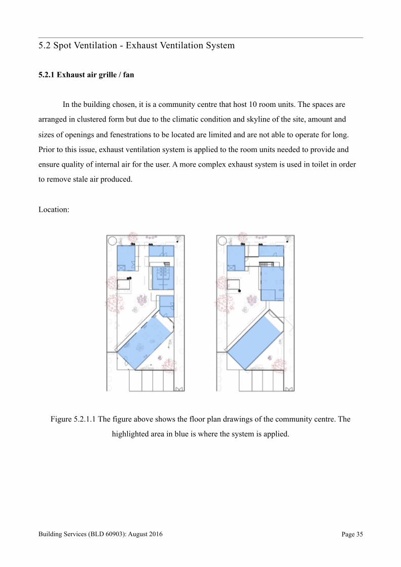
Figure 5.3.1.1 The figure above shows the floor plan drawings of the community centre. The
highlighted area in red is where the system is applied.
The ventilation system work by introducing and extracting approximately equal quantities of
external air and polluted internal air, respectively. It does not temper or remove moisture from the
air before it enters the interior of the space. Whereas, it eliminates dust and pollen from external air
before inserting it into the space.
In a kitchen, the space is consistently is hot and humid condition and pollutants are generated
due to the activities carried out and the machinery in the interior. Thus, the system is applied here to
remove stale air and heat generated to create an appropriate environment for the user. Two fans and
two duct systems is used where one is for the fresh air supply and another one is for the extraction
of stale air.
Building Services (BLD 60903): August 2016 Page !38
5.4 Components
5.4.1 Fan
Fan serves the function of removing hot, humid polluted air. It is often used to introduce external
fresh air into the space to encourage ventilation and reduce the temperature of the space in the
building. It is one of the important components participate in a mechanical ventilation system in
order to complete the air circulation cycle of the ventilation system.
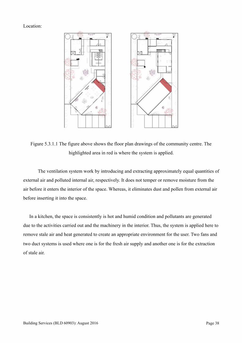
A. Exhaust Fan
Figure 5.4.1.1 The photo above shows an exhaust fan.
Source: http://www.anchor-world.com/panasonic/ventilation.html
It is installed in spaces where openings or fenestrations cannot be operated for long period of time.
It is tasked to remove hot or stale air and also to create an even air circulation.
Fan Diffuser Ductwork
Propeller Fan Door with Grille Air Outlet Galvanised Steel Duct
Single Grille Air Outlet
Ceiling Air Diffuser
Building Services (BLD 60903): August 2016 Page !39
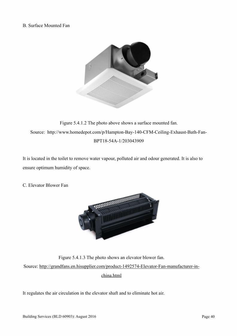
B. Surface Mounted Fan
Figure 5.4.1.2 The photo above shows a surface mounted fan.
Source: http://www.homedepot.com/p/Hampton-Bay-140-CFM-Ceiling-Exhaust-Bath-Fan-
BPT18-54A-1/203043909
It is located in the toilet to remove water vapour, polluted air and odour generated. It is also to
ensure optimum humidity of space.
C. Elevator Blower Fan
Figure 5.4.1.3 The photo shows an elevator blower fan.
Source: http://grandfans.en.hisupplier.com/product-1492574-Elevator-Fan-manufacturer-in-
china.html
It regulates the air circulation in the elevator shaft and to eliminate hot air.
Building Services (BLD 60903): August 2016 Page !40
5.4.2 Diffuser
A diffuser is a mechanical device that usually placed at the end of a ductwork system, where the
removed air is released. It is an outlet used for release of air from the connecting ductwork. They
come in different sizes and shapes, which serve different function depending on the purpose of the
space and the activities carried out by the user.
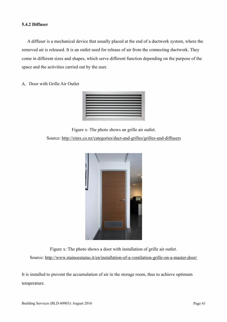
A. Door with Grille Air Outlet
Figure x: The photo shows an grille air outlet.
Source: http://simx.co.nz/categories/duct-and-grilles/grilles-and-diffusers
Figure x: The photo shows a door with installation of grille air outlet.
Source: http://www.stainoestaino.it/en/installation-of-a-ventilation-grille-on-a-master-door/
It is installed to prevent the accumulation of air in the storage room, thus to achieve optimum
temperature.
Building Services (BLD 60903): August 2016 Page !41
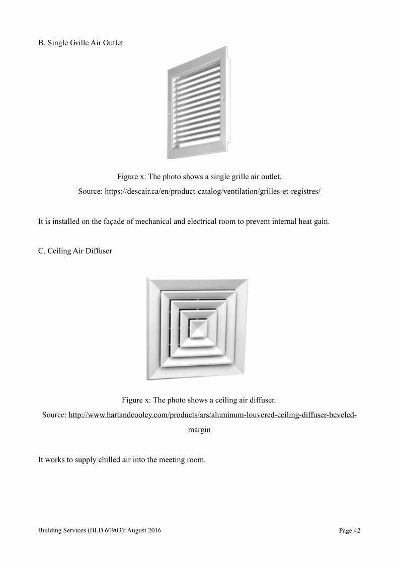
B. Single Grille Air Outlet
Figure x: The photo shows a single grille air outlet.
Source: https://descair.ca/en/product-catalog/ventilation/grilles-et-registres/
It is installed on the façade of mechanical and electrical room to prevent internal heat gain.
C. Ceiling Air Diffuser
Figure x: The photo shows a ceiling air diffuser.
Source: http://www.hartandcooley.com/products/ars/aluminum-louvered-ceiling-diffuser-beveled-
margin
It works to supply chilled air into the meeting room.
Building Services (BLD 60903): August 2016 Page !42

5.4.3 Diffuser
The ductwork system serves the purpose of channeling air into a room or eliminates air out
of the room. Its components some in different shape and size, which affects the sustainability as
well as the efficiency of the installed system. They are generally made of aluminium, copper and
galvanised materials. It is usually connected to the central supply fan or central exhaust fan of the
mechanical ventilation system.
A. Galvanised Steel Duct
Figure x: The photo shows a galvanised steel round duct elbow.
Source: https://www.lowes.com/pl/3-Pelletvent-Imperial/4294859866?page=5
It channels the stale air, grease and heat from the kitchen to external spaces.
Building Services (BLD 60903): August 2016 Page !43
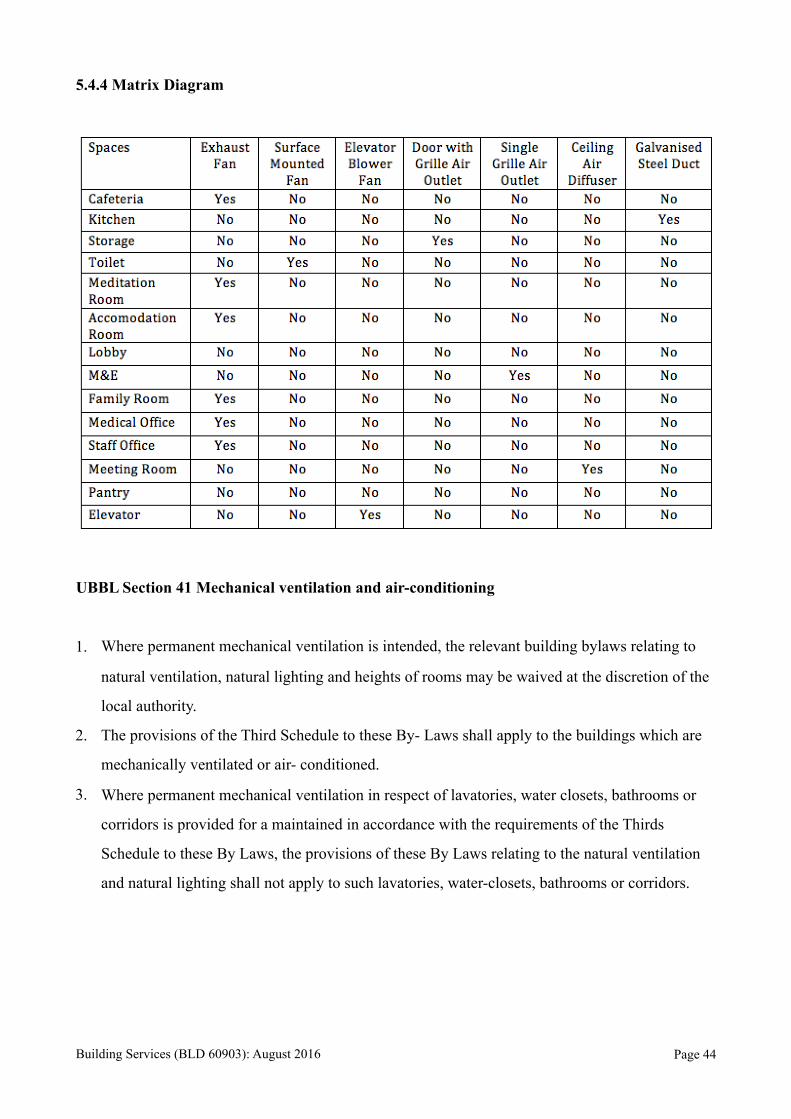
5.4.4 Matrix Diagram
UBBL Section 41 Mechanical ventilation and air-conditioning
1. Where permanent mechanical ventilation is intended, the relevant building bylaws relating to
natural ventilation, natural lighting and heights of rooms may be waived at the discretion of the
local authority.
2. The provisions of the Third Schedule to these By- Laws shall apply to the buildings which are
mechanically ventilated or air- conditioned.
3. Where permanent mechanical ventilation in respect of lavatories, water closets, bathrooms or
corridors is provided for a maintained in accordance with the requirements of the Thirds
Schedule to these By Laws, the provisions of these By Laws relating to the natural ventilation
and natural lighting shall not apply to such lavatories, water-closets, bathrooms or corridors.
Building Services (BLD 60903): August 2016 Page !44
CHAPTER 6.0 AIR CONDITIONING SYSTEM
6.1 Introduction
Elderly Care Centre is separated into three compartment, it consists of 2 storeys of
retails, office suites, café, meditation room and etc. The building is air conditioned by Multi
Split Air-Conditioning System. Multi-splits are multiple split ACs connected to one outdoor
unit. The indoor units can be used individually or at the same time as needed if this is
supported. If both the units are used then the capacity of the ACs will be divided. The fan
and condenser of the outdoor unit will be controlled based on the signals from indoor units.
Split air conditioners are used for small rooms and halls, usually in places where window air
conditioners cannot be installed.
Reasons that Elderly Care Centre chose this system are because multi split air
conditioners are more efficient than room air conditioners. In addition, they saves
installation space, can be used individually or simultaneously, and convenient to operate. To
save energy and running costs, reduce split air conditioner's energy use, to avoid pollution to
the air, so that’s its environment friendly and compact design. Enables indoor units of
different styles and capacities in one system for customised solutions unique to each
residential setting.
A major advantage of a multi-split air conditioning system over a split air
conditioner is the option to add up to four indoor air outlet units to a single outdoor
compressor. With a split air conditioning unit, the system is comprised of one compressor
and one air outlet unit.
With a multi-split system, there is no need for ductwork. It is a complete system
designed specifically for individual interior areas. This is a significant advantage over other
systems since you do not have to factor in the cost for ductwork materials and installation.
Unlike a conventional system that works off one thermostat to control temperatures, a multi-
split system provides individual control of each room’s temperatures. This gives an
Building Services (BLD 60903): August 2016 Page !45
opportunity to regulate the temperature in each room according to personal preference,
providing additional money saving advantage as can heat or cool only those rooms are using
versus the entire house.
Multi-split systems are designed with interior compatibility in mind. The air outlet
that disperses the air is relatively small, aesthetically pleasing to the eye, and can be easily
installed flush against a wall, can mix and match the different style air outlets.
Multi-split systems are flexible and easy to install, requiring less labour than
traditional systems. They are also cost effective when compared to central air systems
although they are typically more expensive than a window or through-the-wall air
conditioner.
6.2 Ductless Heating Ventilation and Air-Conditioning (HVAC) System
The split air conditioning system adopted in Elderly Care Centre is designed to
operate by HVAC. Multi split-system air-conditioners have numerous potential applications
in residential, commercial, and institutional buildings. The most common applications are in
multifamily housing or as retrofit add-ons to houses with "non-ducted" heating systems,
such as hydronic, radiant panels, and space.
Like central systems, multi splits have two main components: an outdoor
compressor/condenser, and an indoor air-handling unit. A conduit, which houses the power
cable, refrigerant tubing, suction tubing, and a condensate drain, links the outdoor and
indoor units.This is to allow the building owners have more control over the heating or
cooling units.
Building Services (BLD 60903): August 2016 Page !46
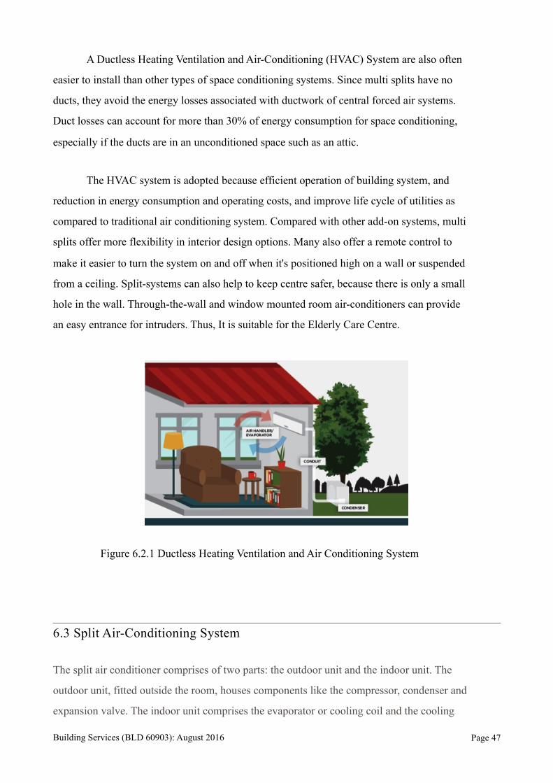
A Ductless Heating Ventilation and Air-Conditioning (HVAC) System are also often
easier to install than other types of space conditioning systems. Since multi splits have no
ducts, they avoid the energy losses associated with ductwork of central forced air systems.
Duct losses can account for more than 30% of energy consumption for space conditioning,
especially if the ducts are in an unconditioned space such as an attic.
The HVAC system is adopted because efficient operation of building system, and
reduction in energy consumption and operating costs, and improve life cycle of utilities as
compared to traditional air conditioning system. Compared with other add-on systems, multi
splits offer more flexibility in interior design options. Many also offer a remote control to
make it easier to turn the system on and off when it's positioned high on a wall or suspended
from a ceiling. Split-systems can also help to keep centre safer, because there is only a small
hole in the wall. Through-the-wall and window mounted room air-conditioners can provide
an easy entrance for intruders. Thus, It is suitable for the Elderly Care Centre.
Figure 6.2.1 Ductless Heating Ventilation and Air Conditioning System
6.3 Split Air-Conditioning System
The split air conditioner comprises of two parts: the outdoor unit and the indoor unit. The
outdoor unit, fitted outside the room, houses components like the compressor, condenser and
expansion valve. The indoor unit comprises the evaporator or cooling coil and the cooling
Building Services (BLD 60903): August 2016 Page !47
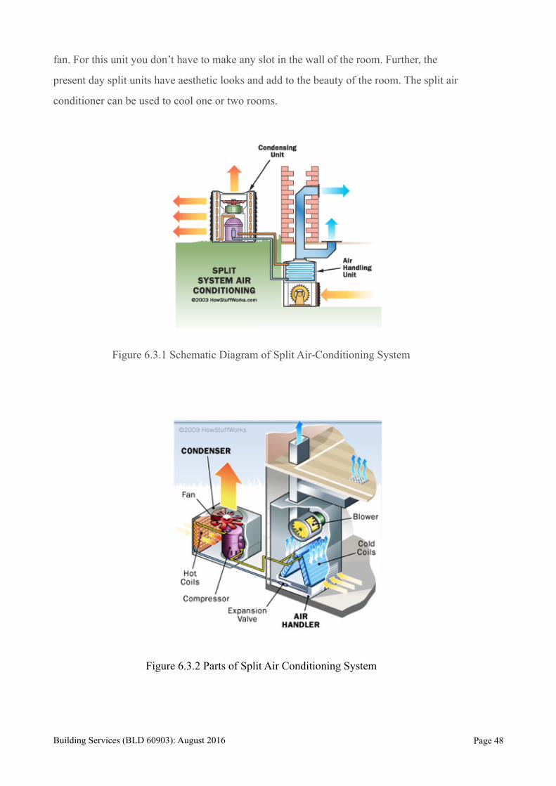
fan. For this unit you don’t have to make any slot in the wall of the room. Further, the
present day split units have aesthetic looks and add to the beauty of the room. The split air
conditioner can be used to cool one or two rooms.
Figure 6.3.1 Schematic Diagram of Split Air-Conditioning System
Figure 6.3.2 Parts of Split Air Conditioning System
Building Services (BLD 60903): August 2016 Page !48
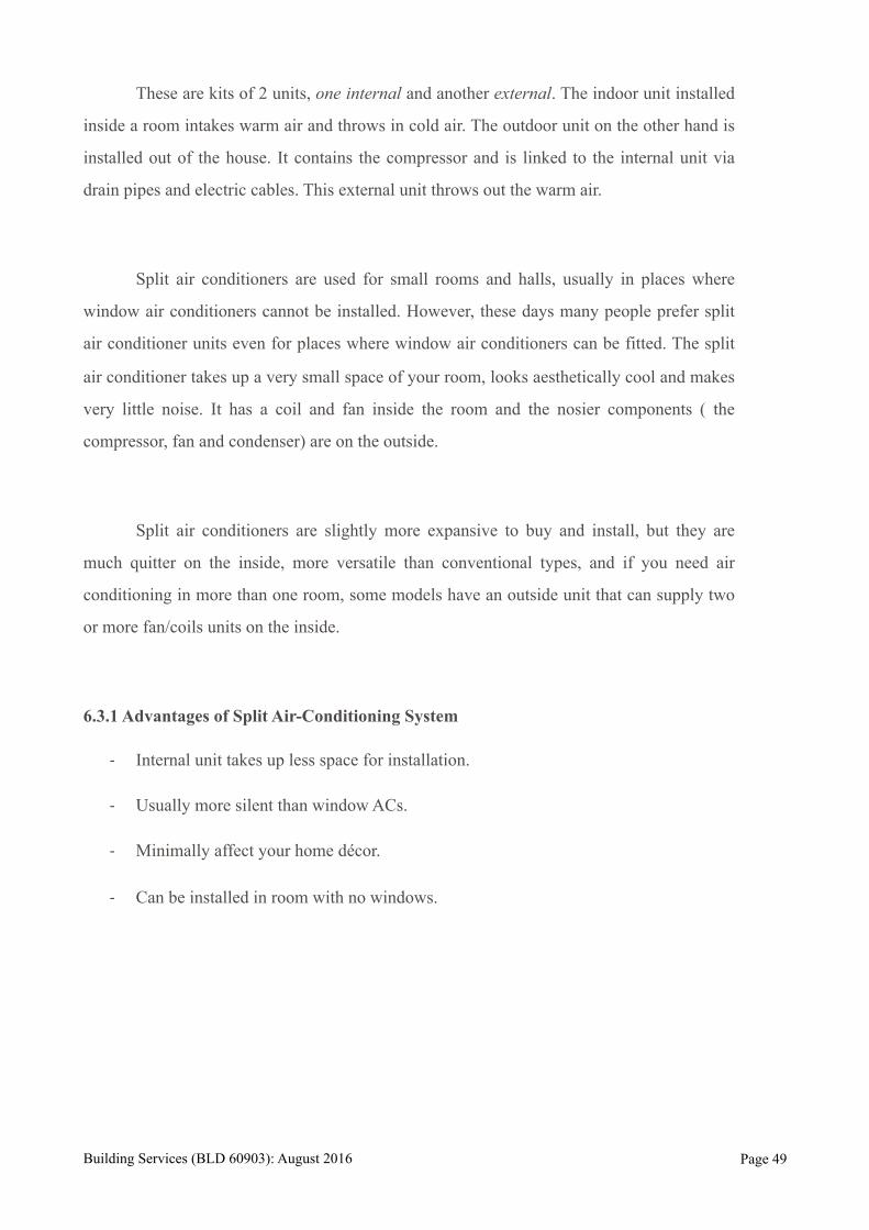
These are kits of 2 units, one internal and another external. The indoor unit installed
inside a room intakes warm air and throws in cold air. The outdoor unit on the other hand is
installed out of the house. It contains the compressor and is linked to the internal unit via
drain pipes and electric cables. This external unit throws out the warm air.
Split air conditioners are used for small rooms and halls, usually in places where
window air conditioners cannot be installed. However, these days many people prefer split
air conditioner units even for places where window air conditioners can be fitted. The split
air conditioner takes up a very small space of your room, looks aesthetically cool and makes
very little noise. It has a coil and fan inside the room and the nosier components ( the
compressor, fan and condenser) are on the outside.
Split air conditioners are slightly more expansive to buy and install, but they are
much quitter on the inside, more versatile than conventional types, and if you need air
conditioning in more than one room, some models have an outside unit that can supply two
or more fan/coils units on the inside.
6.3.1 Advantages of Split Air-Conditioning System
- Internal unit takes up less space for installation.
- Usually more silent than window ACs.
- Minimally affect your home décor.
- Can be installed in room with no windows.
Building Services (BLD 60903): August 2016 Page !49
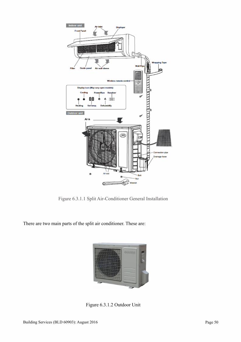
Figure 6.3.1.1 Split Air-Conditioner General Installation
There are two main parts of the split air conditioner. These are:
Figure 6.3.1.2 Outdoor Unit
Building Services (BLD 60903): August 2016 Page !50
A. Outdoor Unit
This unit houses important components of the air conditioner like the compressor, condenser
coil and also the expansion coil or capillary tubing. This unit is installed outside the room or office
space which is to be cooled. The compressor is the maximum noise making part of the air
conditioner, and since in the split air conditioner, it is located outside the room, the major source of
noise is eliminated. In the outdoor unit there is a fan that blows air over the condenser thus cooling
the compressed Freon gas in it. This gas passes through the expansion coil and gets converted into
low pressure, low temperature partial gas and partial liquid Freon fluid.
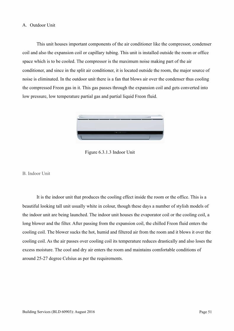
Figure 6.3.1.3 Indoor Unit
B. Indoor Unit
It is the indoor unit that produces the cooling effect inside the room or the office. This is a
beautiful looking tall unit usually white in colour, though these days a number of stylish models of
the indoor unit are being launched. The indoor unit houses the evaporator coil or the cooling coil, a
long blower and the filter. After passing from the expansion coil, the chilled Freon fluid enters the
cooling coil. The blower sucks the hot, humid and filtered air from the room and it blows it over the
cooling coil. As the air passes over cooling coil its temperature reduces drastically and also loses the
excess moisture. The cool and dry air enters the room and maintains comfortable conditions of
around 25-27 degree Celsius as per the requirements.
Building Services (BLD 60903): August 2016 Page !51

6.3.2 Difference between Split and Multi Split Air Conditioning System
Figure 6.3.2.1 Split Air-Conditioning System
Split
• Connects one indoor unit to an outdoor unit.
• Installs simply and unobtrusively to buildings with no need for ductwork.
• Delivers a sophisticated air conditioning solution to single zone interior spaces at an
affordable price.
• Provides a simple solution for one-room additions.
Figure 6.3.2.2 Multi Split Air-Conditioning System
Building Services (BLD 60903): August 2016 Page !52
Multi-split
• Connects up to five indoor units to a single outdoor unit.
• Installs a complete air conditioning system to multiple zone interior spaces with no need
for ductwork.
• Provides individual control of room temperature settings.
• Enables indoor units of different styles and capacities in one system for customised
solutions unique to each residential setting.
6.3.3 Type of Split Air-Conditioning System
1. Wall mounted
2. Floor mounted / Tower Air-Conditioner
3. Ceiling mounted / Cassette Air-Conditioner
4. Multi Split Air-Conditioner System
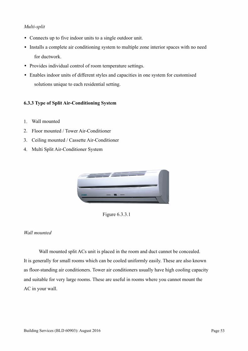
Figure 6.3.3.1
Wall mounted
Wall mounted split ACs unit is placed in the room and duct cannot be concealed.
It is generally for small rooms which can be cooled uniformly easily. These are also known
as floor-standing air conditioners. Tower air conditioners usually have high cooling capacity
and suitable for very large rooms. These are useful in rooms where you cannot mount the
AC in your wall.
Building Services (BLD 60903): August 2016 Page !53

Figure 6.3.3.2
Ceiling mounted / Cassette Air-Conditioner
These space-saving ACs are shaped like cassettes and are designed to be installed on
ceilings. The panel of these air conditioners is designed to blend with all kinds of home
décor. They are stylish, and are known to deliver fantastic performances. Most cassette type
air conditioners require no ducting.
Figure 6.3.3.3
Multi Split Air-Conditioning System
Multi-splits are multiple split ACs connected to one outdoor unit. The indoor units can be
used individually or at the same time as needed if this is supported. If both the units are used
then the capacity of the ACs will be divided. The fan and condenser of the outdoor unit will
be controlled based on the signals from indoor units.
Building Services (BLD 60903): August 2016 Page !54

6.3.4 Advantages and Disadvantages of Multi Split Air-Conditioning System
Advantages
- Saves installation space
- Can be used individually or simultaneously
- Independent control
- Compact Design
- Good EER
- Saves on running costs
- Convenient and economical
Disadvantages
- Expensive compared to a single unit split AC
- Limited range of capacities and models
- More prone to leakage as number of indoor units increases
6.3.5 Refrigeration Cycle
Figure 6.3.5.1 Schematic Diagram shows the Refrigerant Cycle.
Building Services (BLD 60903): August 2016 Page !55
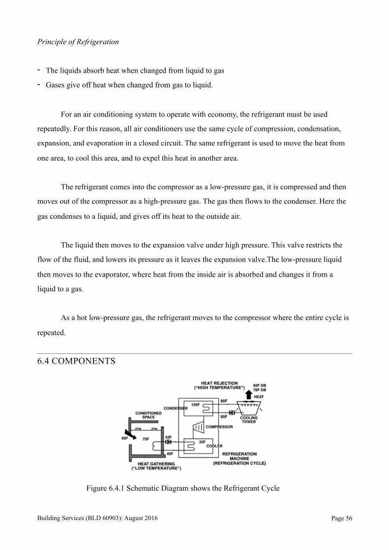
Principle of Refrigeration
- The liquids absorb heat when changed from liquid to gas
- Gases give off heat when changed from gas to liquid.
For an air conditioning system to operate with economy, the refrigerant must be used
repeatedly. For this reason, all air conditioners use the same cycle of compression, condensation,
expansion, and evaporation in a closed circuit. The same refrigerant is used to move the heat from
one area, to cool this area, and to expel this heat in another area.
The refrigerant comes into the compressor as a low-pressure gas, it is compressed and then
moves out of the compressor as a high-pressure gas. The gas then flows to the condenser. Here the
gas condenses to a liquid, and gives off its heat to the outside air.
The liquid then moves to the expansion valve under high pressure. This valve restricts the
flow of the fluid, and lowers its pressure as it leaves the expansion valve.The low-pressure liquid
then moves to the evaporator, where heat from the inside air is absorbed and changes it from a
liquid to a gas.
As a hot low-pressure gas, the refrigerant moves to the compressor where the entire cycle is
repeated.
6.4 COMPONENTS
Figure 6.4.1 Schematic Diagram shows the Refrigerant Cycle
Building Services (BLD 60903): August 2016 Page !56
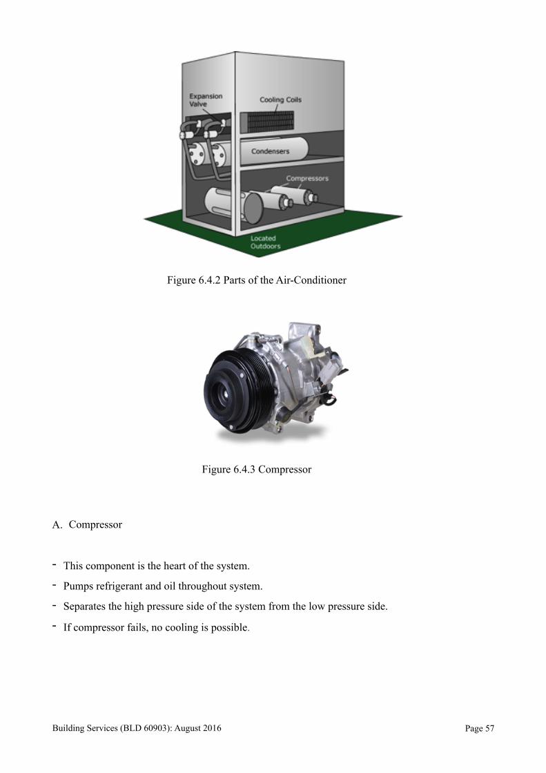
Figure 6.4.2 Parts of the Air-Conditioner
Figure 6.4.3 Compressor
A. Compressor
- This component is the heart of the system.
- Pumps refrigerant and oil throughout system.
- Separates the high pressure side of the system from the low pressure side.
- If compressor fails, no cooling is possible.
Building Services (BLD 60903): August 2016 Page !57
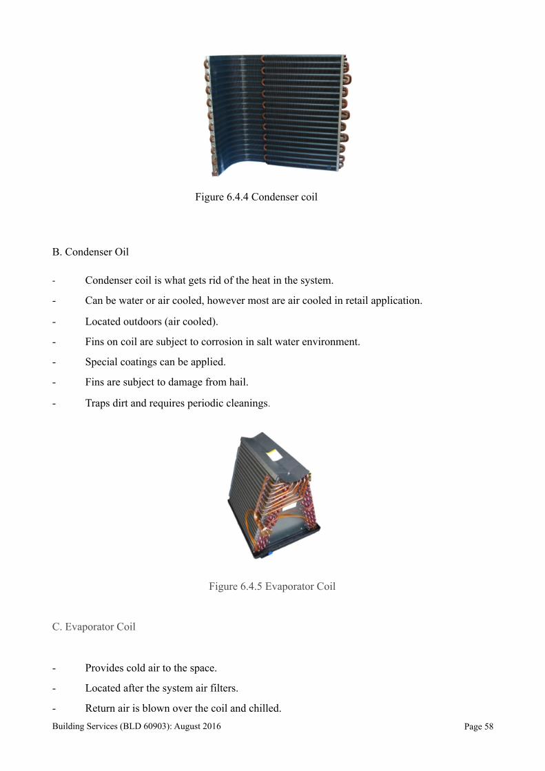
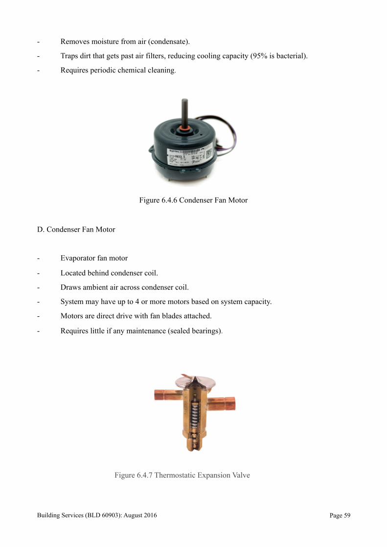
Figure 6.4.4 Condenser coil
B. Condenser Oil
- Condenser coil is what gets rid of the heat in the system.
- Can be water or air cooled, however most are air cooled in retail application.
- Located outdoors (air cooled).
- Fins on coil are subject to corrosion in salt water environment.
- Special coatings can be applied.
- Fins are subject to damage from hail.
- Traps dirt and requires periodic cleanings.
Figure 6.4.5 Evaporator Coil
C. Evaporator Coil
- Provides cold air to the space.
- Located after the system air filters.
- Return air is blown over the coil and chilled. Building Services (BLD 60903): August 2016 Page !58
- Removes moisture from air (condensate).
- Traps dirt that gets past air filters, reducing cooling capacity (95% is bacterial).
- Requires periodic chemical cleaning.
Figure 6.4.6 Condenser Fan Motor
D. Condenser Fan Motor
- Evaporator fan motor
- Located behind condenser coil.
- Draws ambient air across condenser coil.
- System may have up to 4 or more motors based on system capacity.
- Motors are direct drive with fan blades attached.
- Requires little if any maintenance (sealed bearings).
Figure 6.4.7 Thermostatic Expansion Valve
Building Services (BLD 60903): August 2016 Page !59
E. Thermostatic Expansion Valve
- Located at the evaporator coil.
- Provides the correct amount of refrigerant to the evaporator coil for proper cooling.
- Separates the high pressure side of the system from the low pressure side.
- Failure could cause compressor failure and loss of system cooling capacity.
- Frequently overlooked in diagnosing system problems.
- Requires manual setting of superheat for proper operation.
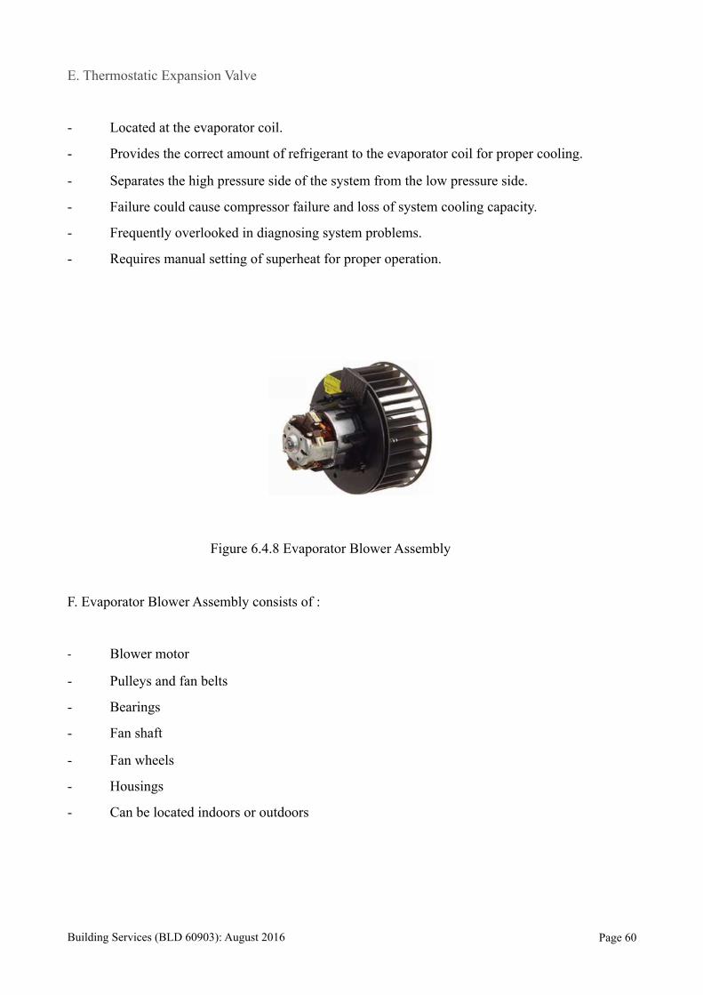
Figure 6.4.8 Evaporator Blower Assembly
F. Evaporator Blower Assembly consists of :
- Blower motor
- Pulleys and fan belts
- Bearings
- Fan shaft
- Fan wheels
- Housings
- Can be located indoors or outdoors
Building Services (BLD 60903): August 2016 Page !60
UBBL requirements or related regulations
41. Mechanicals ventilation and air-conditioning.
(1) Where permanent mechanical ventilation or air-conditioning is intended, the relevant building
by-laws relating to natural ventilation, natural lighting and heights of rooms may be waived at the
discretion of the local authority.
(2) Any application for the waiver of the relevant by-laws shall only be considered if in addition to
the permanent air-conditioning system there is provided alternative approved means of ventilating
the air-conditioned enclosure, such that within half an hour of the air-conditioning system failing,
not less than the stipulated volume of fresh air specified hereinafter shall be introduced into the
enclosure during the period when the air-conditioning system is not functioning.
(3) The provisions of the Third Schedule to these By-laws shall apply to buildings which are
mechanically ventilated or air-conditioned.
(4) Where permanent mechanical ventilation in respect of lavatories, water-closets, bathrooms or
corridors is provided for and maintained in accordance with the requirements of the Third Schedule
to these By-laws, the provisions of these By-laws relating to natural ventilation and natural lighting
shall not apply to such lavatories, water-closets, bathrooms or corridors.
Building Services (BLD 60903): August 2016 Page !61

CHAPTER 7.0 FIRE PROTECTION SYSTEM
7.1 Introduction
Fire is the rapid oxidation of a material in the exothermic chemical process of combustion,
releasing heat, light, and various reaction products. Fires start when a flammable or a combustible
material, in combination with a sufficient quantity of an oxidizer such as oxygen gas or another
oxygen-rich compound (though non-oxygen oxidisers exist), is exposed to a source of heat or
ambient temperature above the flash point for the fuel/oxidiser mix, and is able to sustain a rate of
rapid oxidation that produces a chain reaction.
7.1.1 Fire Protection System Overview
Elderly Centre is sitting in a bungalow lot in a housing area. The cafeteria and kitchen of the elderly
centre poses the highest risk for fire, so more attention is given on the particular clustered building,
with appliance of a better fire protection system.
7.2 Passive Fire Protection System
Passive Fire Protection (PFP) is a form of fire safety provision that remains dormant, or
inert, during normal conditions but becomes active in a fire situation. Passive Fire Protection
System is the use of fire barrier systems that are integrated into the structure of a building, which is
designed to contain fires or slow their spread. The purpose of PFP is to contain the spread of fire for
sufficient time to permit:
i) The safe evacuation of all occupants of the premises and
ii) The arrival of the fire brigade.
The person responsible for fire safety also has a duty of care towards any members of the
emergency services, e.g. fire fighters, who may have to enter the premises during the course of a
Building Services (BLD 60903): August 2016 Page !62

fire; in slowing the spread of flames, smoke and hot gases, PFP also serves to ensure the building
remains as safe as possible for entry in this situation.
7.1.1 Emergency Exit Signage
Figure 7.1.1.1 Emergency exit sign above escape door
The emergency exit signage is found above the fire rated door at the back of each emergency exits.
The sign directs occupants to a shortcut or an alley, where fireman can access for search and rescue.
According to UBBL 1984 Section 172: Emergency Exit Signs
(1) Storey exits and access to such exits shall be marked by readily visible signs and shall not be
obscured by any decorations, furnishings or other equipment.
(2) A sign reading “KELUAR” with an arrow indicating the direction shall be placed in every
location where the direction of travel to reach the nearest exit is not immediately apparent.
(3) Every exit sign shall have the word “KELUAR” in plainly legible letters not less than 150
millimetres high with principle strokes of the letters not less than 18 millimetres wide. The lettering
shall be in red against a black background.
(4) All exit signs shall be illuminated continuously during periods of occupancy.
(5) Illuminated signs shall be provided with two electric lamps of not less than fifteen watts
each.
7.1.2 Emergency Light
Emergency light functions automatically during power failure due to fire, it is fitted with
charged battery to illuminate along exit access pathways leading to exits, exit stairs, aisles, Building Services (BLD 60903): August 2016 Page !63
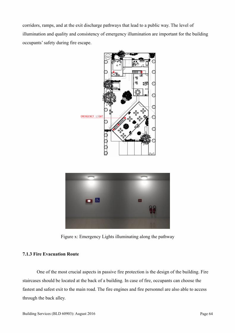
corridors, ramps, and at the exit discharge pathways that lead to a public way. The level of
illumination and quality and consistency of emergency illumination are important for the building
occupants’ safety during fire escape.
Figure x: Emergency Lights illuminating along the pathway
7.1.3 Fire Evacuation Route
One of the most crucial aspects in passive fire protection is the design of the building. Fire
staircases should be located at the back of a building. In case of fire, occupants can choose the
fastest and safest exit to the main road. The fire engines and fire personnel are also able to access
through the back alley.
Building Services (BLD 60903): August 2016 Page !64
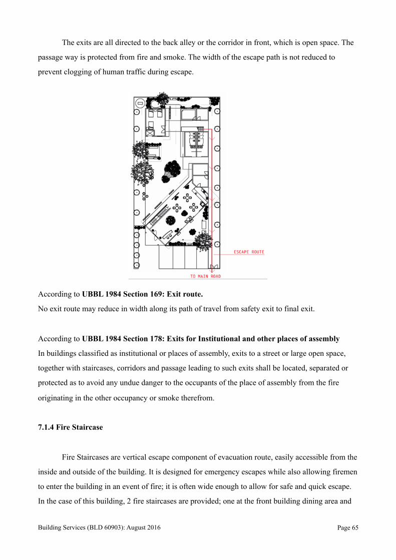
The exits are all directed to the back alley or the corridor in front, which is open space. The
passage way is protected from fire and smoke. The width of the escape path is not reduced to
prevent clogging of human traffic during escape.
According to UBBL 1984 Section 169: Exit route.
No exit route may reduce in width along its path of travel from safety exit to final exit.
According to UBBL 1984 Section 178: Exits for Institutional and other places of assembly
In buildings classified as institutional or places of assembly, exits to a street or large open space,
together with staircases, corridors and passage leading to such exits shall be located, separated or
protected as to avoid any undue danger to the occupants of the place of assembly from the fire
originating in the other occupancy or smoke therefrom.
7.1.4 Fire Staircase
Fire Staircases are vertical escape component of evacuation route, easily accessible from the
inside and outside of the building. It is designed for emergency escapes while also allowing firemen
to enter the building in an event of fire; it is often wide enough to allow for safe and quick escape.
In the case of this building, 2 fire staircases are provided; one at the front building dining area and
Building Services (BLD 60903): August 2016 Page !65
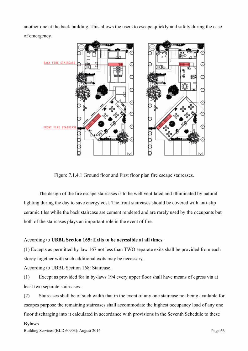
another one at the back building. This allows the users to escape quickly and safely during the case
of emergency.
Figure 7.1.4.1 Ground floor and First floor plan fire escape staircases.
The design of the fire escape staircases is to be well ventilated and illuminated by natural
lighting during the day to save energy cost. The front staircases should be covered with anti-slip
ceramic tiles while the back staircase are cement rendered and are rarely used by the occupants but
both of the staircases plays an important role in the event of fire.
According to UBBL Section 165: Exits to be accessible at all times.
(1) Excepts as permitted by-law 167 not less than TWO separate exits shall be provided from each
storey together with such additional exits may be necessary.
According to UBBL Section 168: Staircase.
(1) Except as provided for in by-laws 194 every upper floor shall have means of egress via at
least two separate staircases.
(2) Staircases shall be of such width that in the event of any one staircase not being available for
escapes purpose the remaining staircases shall accommodate the highest occupancy load of any one
floor discharging into it calculated in accordance with provisions in the Seventh Schedule to these
Bylaws. Building Services (BLD 60903): August 2016 Page !66
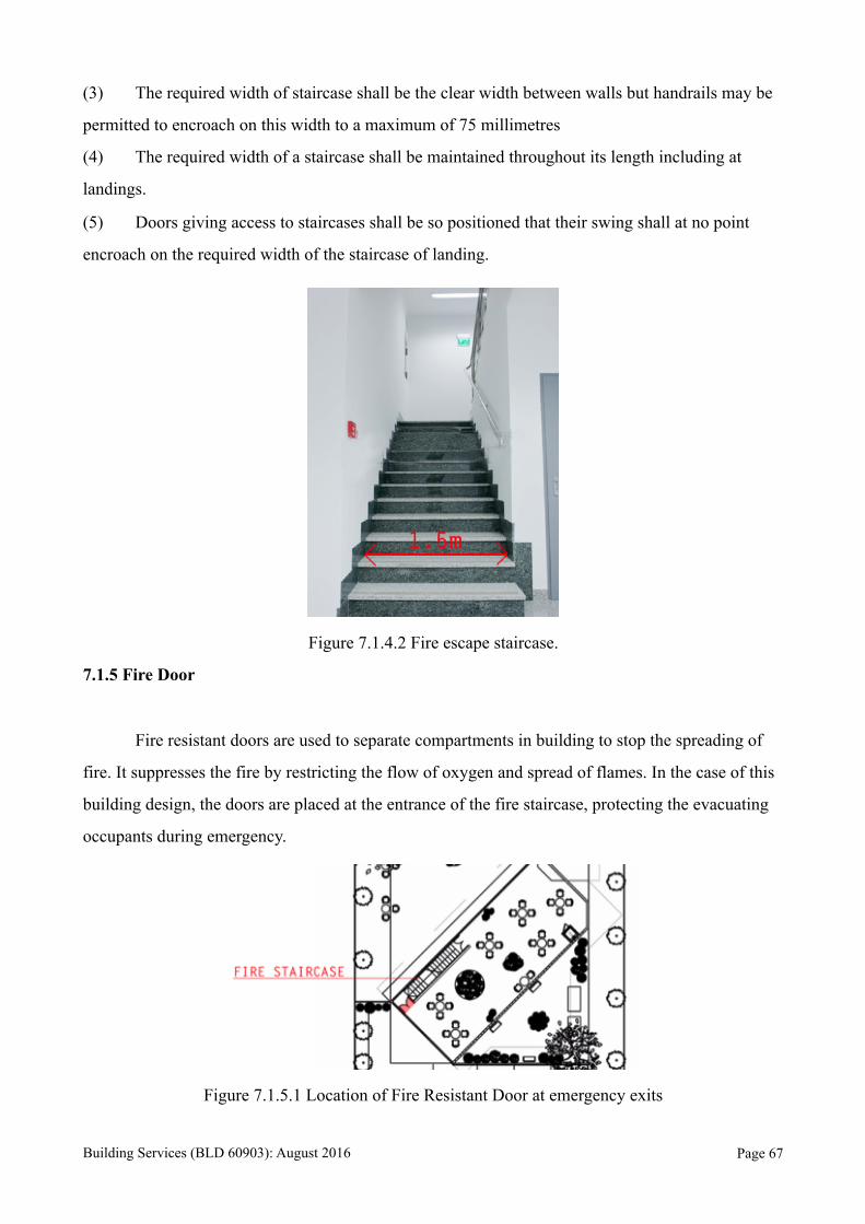
(3) The required width of staircase shall be the clear width between walls but handrails may be
permitted to encroach on this width to a maximum of 75 millimetres
(4) The required width of a staircase shall be maintained throughout its length including at
landings.
(5) Doors giving access to staircases shall be so positioned that their swing shall at no point
encroach on the required width of the staircase of landing.
Figure 7.1.4.2 Fire escape staircase.
7.1.5 Fire Door
Fire resistant doors are used to separate compartments in building to stop the spreading of
fire. It suppresses the fire by restricting the flow of oxygen and spread of flames. In the case of this
building design, the doors are placed at the entrance of the fire staircase, protecting the evacuating
occupants during emergency.
Figure 7.1.5.1 Location of Fire Resistant Door at emergency exits
Building Services (BLD 60903): August 2016 Page !67
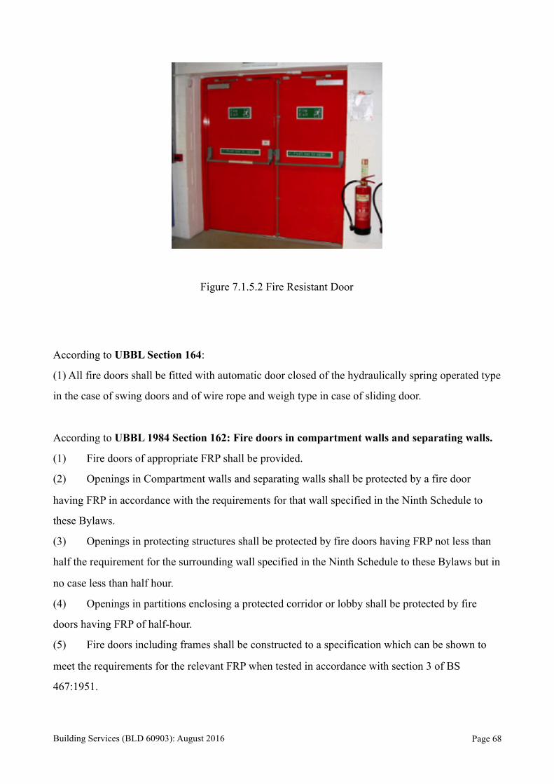
Figure 7.1.5.2 Fire Resistant Door
According to UBBL Section 164:
(1) All fire doors shall be fitted with automatic door closed of the hydraulically spring operated type
in the case of swing doors and of wire rope and weigh type in case of sliding door.
According to UBBL 1984 Section 162: Fire doors in compartment walls and separating walls.
(1) Fire doors of appropriate FRP shall be provided.
(2) Openings in Compartment walls and separating walls shall be protected by a fire door
having FRP in accordance with the requirements for that wall specified in the Ninth Schedule to
these Bylaws.
(3) Openings in protecting structures shall be protected by fire doors having FRP not less than
half the requirement for the surrounding wall specified in the Ninth Schedule to these Bylaws but in
no case less than half hour.
(4) Openings in partitions enclosing a protected corridor or lobby shall be protected by fire
doors having FRP of half-hour.
(5) Fire doors including frames shall be constructed to a specification which can be shown to
meet the requirements for the relevant FRP when tested in accordance with section 3 of BS
467:1951.
Building Services (BLD 60903): August 2016 Page !68
7.3 Active Fire Protection System
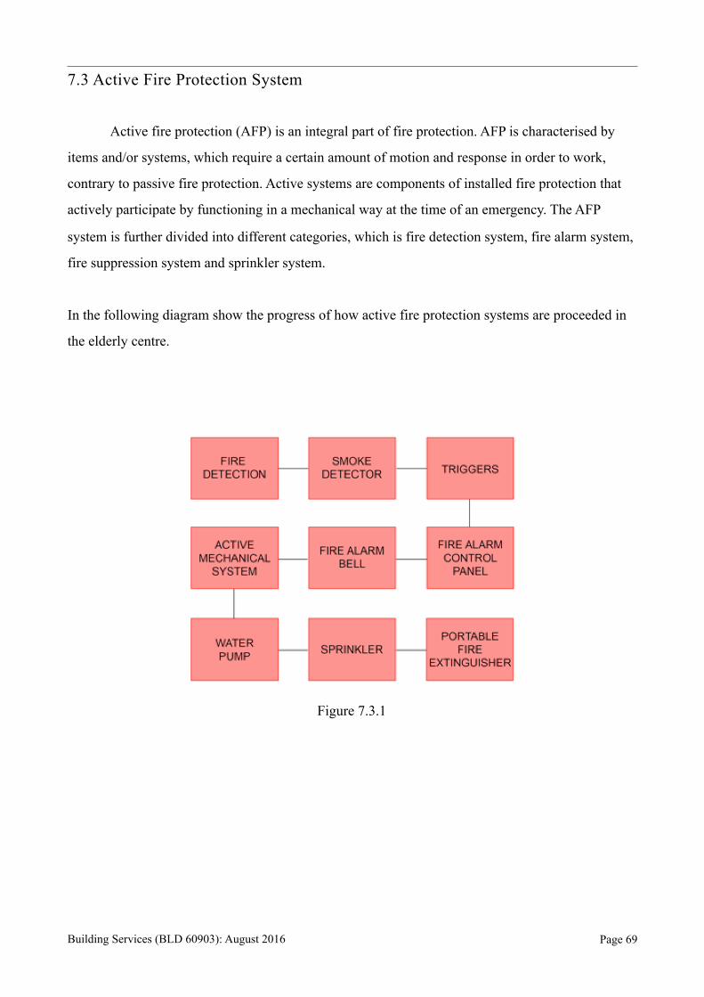
Active fire protection (AFP) is an integral part of fire protection. AFP is characterised by
items and/or systems, which require a certain amount of motion and response in order to work,
contrary to passive fire protection. Active systems are components of installed fire protection that
actively participate by functioning in a mechanical way at the time of an emergency. The AFP
system is further divided into different categories, which is fire detection system, fire alarm system,
fire suppression system and sprinkler system.
In the following diagram show the progress of how active fire protection systems are proceeded in
the elderly centre.
Figure 7.3.1
Building Services (BLD 60903): August 2016 Page !69
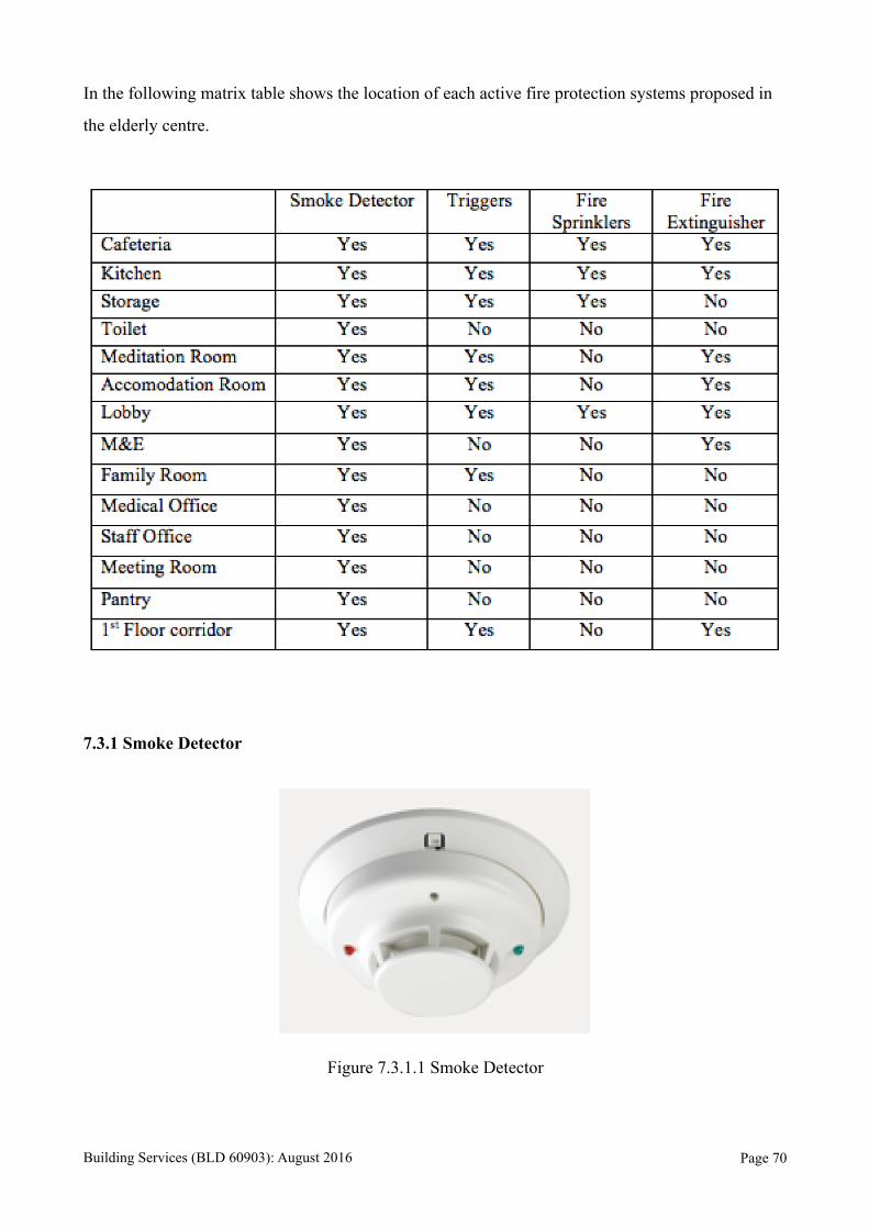
In the following matrix table shows the location of each active fire protection systems proposed in
the elderly centre.
7.3.1 Smoke Detector
Figure 7.3.1.1 Smoke Detector
Building Services (BLD 60903): August 2016 Page !70
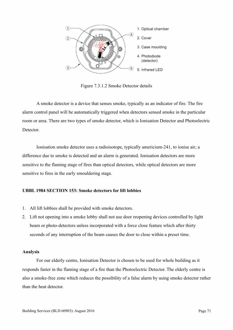
Figure 7.3.1.2 Smoke Detector details
A smoke detector is a device that senses smoke, typically as an indicator of fire. The fire
alarm control panel will be automatically triggered when detectors sensed smoke in the particular
room or area. There are two types of smoke detector, which is Ionisation Detector and Photoelectric
Detector.
Ionisation smoke detector uses a radioisotope, typically americium-241, to ionise air; a
difference due to smoke is detected and an alarm is generated. Ionisation detectors are more
sensitive to the flaming stage of fires than optical detectors, while optical detectors are more
sensitive to fires in the early smouldering stage.
UBBL 1984 SECTION 153: Smoke detectors for lift lobbies
1. All lift lobbies shall be provided with smoke detectors.
2. Lift not opening into a smoke lobby shall not use door reopening devices controlled by light
beam or photo-detectors unless incorporated with a force close feature which after thirty
seconds of any interruption of the beam causes the door to close within a preset time.
Analysis
For our elderly centre, Ionisation Detector is chosen to be used for whole building as it
responds faster in the flaming stage of a fire than the Photoelectric Detector. The elderly centre is
also a smoke-free zone which reduces the possibility of a false alarm by using smoke detector rather
than the heat detector.
Building Services (BLD 60903): August 2016 Page !71
7.3.2 Triggers
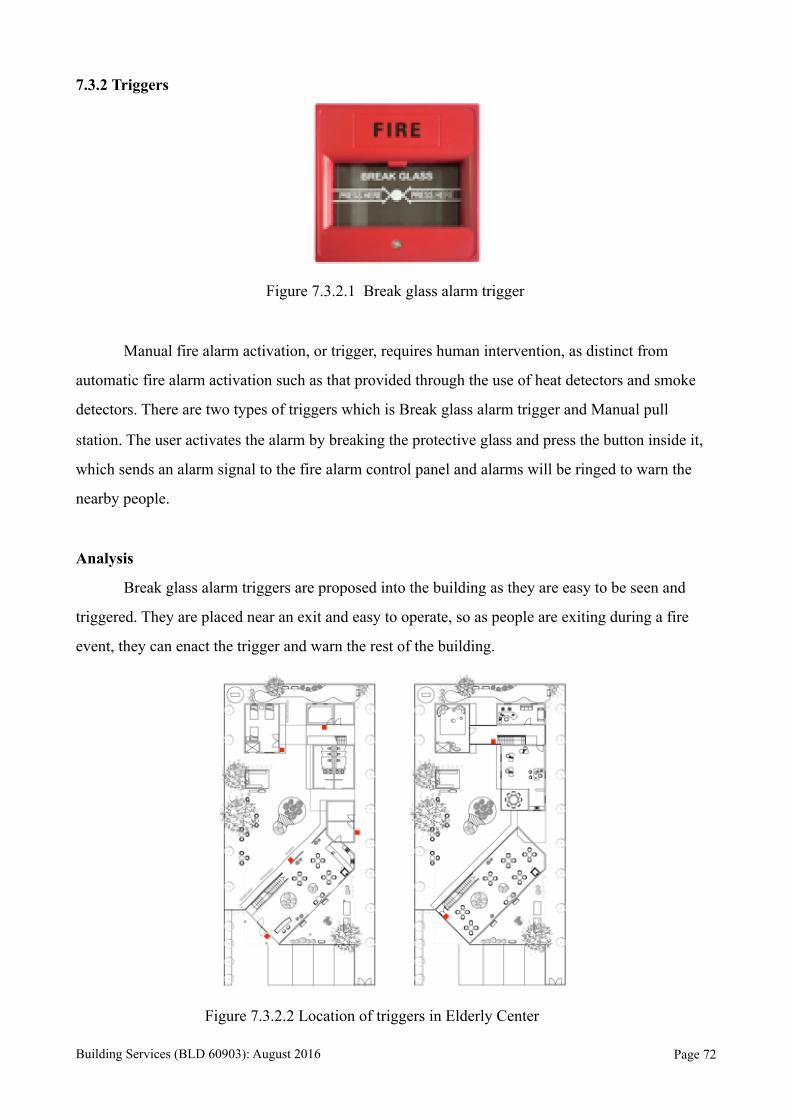
Figure 7.3.2.1 Break glass alarm trigger
Manual fire alarm activation, or trigger, requires human intervention, as distinct from
automatic fire alarm activation such as that provided through the use of heat detectors and smoke
detectors. There are two types of triggers which is Break glass alarm trigger and Manual pull
station. The user activates the alarm by breaking the protective glass and press the button inside it,
which sends an alarm signal to the fire alarm control panel and alarms will be ringed to warn the
nearby people.
Analysis
Break glass alarm triggers are proposed into the building as they are easy to be seen and
triggered. They are placed near an exit and easy to operate, so as people are exiting during a fire
event, they can enact the trigger and warn the rest of the building.
Figure 7.3.2.2 Location of triggers in Elderly Center
Building Services (BLD 60903): August 2016 Page !72

7.3.3 Fire Alarm Bell
Figure 7.3.3.1 Fire Alarm Bell
An alarm device or system of alarm devices gives an repetitive loud ringing sound to alert
the occupants in the building of an emergency. The alarm bell functions by means of
an electromagnet. When an electric current is applied, it produces a repetitive buzzing or clanging
sound.
UBBL 1984 SECTION 237: Fire Alarms.
1. Fire Alarms shall be provided in accordance with the Tenth Schedule to these By-laws.
2. All premises and buildings with gross floor area excluding car park and storage areas exceeding
9290 square meters or exceeding 30.5 meters in height shall be provided with a two stage alarm
system with evacuation (continuous signal) to be given immediately in the affected section of
the premises while an alert (intermittent signal) be given in adjoining section.
3. Provision shall be made for general evacuation of the premises by action of a master control.
Analysis
Two stage alarm system is proposed into the elderly centre as a general alarm would cause
undue distress to the occupants. The evacuation of the occupants is difficult and could be physically
and psychologically harmful. Therefor, two-stage alarm systems are used to reduce the possibility
of false alarm.
Building Services (BLD 60903): August 2016 Page !73
7.3.4 Fire Alarm Control Panel
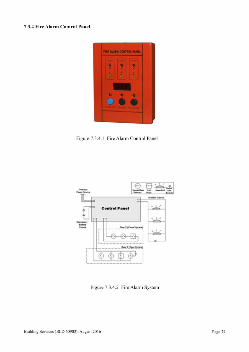
Figure 7.3.4.1 Fire Alarm Control Panel
Figure 7.3.4.2 Fire Alarm System
Building Services (BLD 60903): August 2016 Page !74
The Fire Alarm Control Panel (FACP), or Fire Alarm Control Unit (FACU), is the
controlling component of a Fire Alarm System. The panel receives information from environmental
sensors designed to detect changes associated with fire, monitors their operational integrity and
provides for automatic control of equipment, and transmission of information necessary to prepare
the facility for fire based on a predetermined sequence.
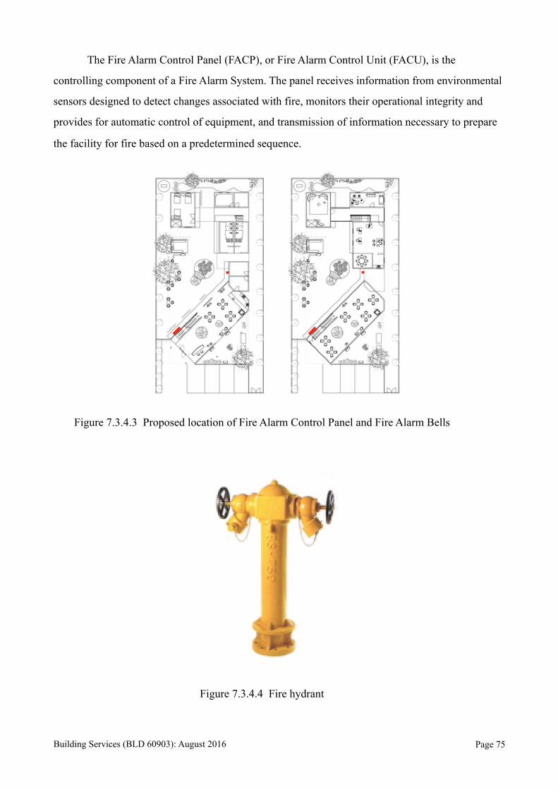
Figure 7.3.4.3 Proposed location of Fire Alarm Control Panel and Fire Alarm Bells
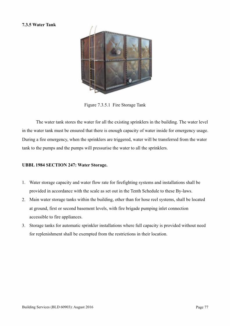
Figure 7.3.4.4 Fire hydrant
Building Services (BLD 60903): August 2016 Page !75

Figure 7.3.4.5 Location of site and Fire Hydrant
A fire hydrant is an active fire protection measure, and a connection point by which
firefighters can tap into a water supply. The user attaches a hose to the fire hydrant, then opens
a valve on the hydrant to provide a powerful flow of water, on the order of 350 kPa (50 lbf/in²) (this
pressure varies according to region and depends on various factors including the size and location
of the attached water main). This user can attach this hose to a fire engine, which can use a
powerful pump to boost the water pressure and possibly split it into multiple streams.
UBBL 1984 SECTION 225: Detecting and extinguishing fire.
1. Every building shall be provided with means of detecting and extinguishing fire and with fire
alarms together with illuminated exit signs in accordance with the requirements as specified in
the Tenth Schedule to these By-Laws.
2. Every building shall be served by at least one fire hydrant located not more than 91.5 metres
from the nearest point of fire brigade access.
3. Depending on the size and location of the building and the provision of access for fire
Appliances, additional fire hydrant shall be provided as may be required by the Fire Authority.
Analysis
The distance between the water hydrant and the site is within 6 meters, allowing fireman to
access the water hydrant easily and utilise it efficiently. Since there is a water hydrant nearby, only
an additional water tank is needed for the Sprinkler system.
Building Services (BLD 60903): August 2016 Page !76
7.3.5 Water Tank
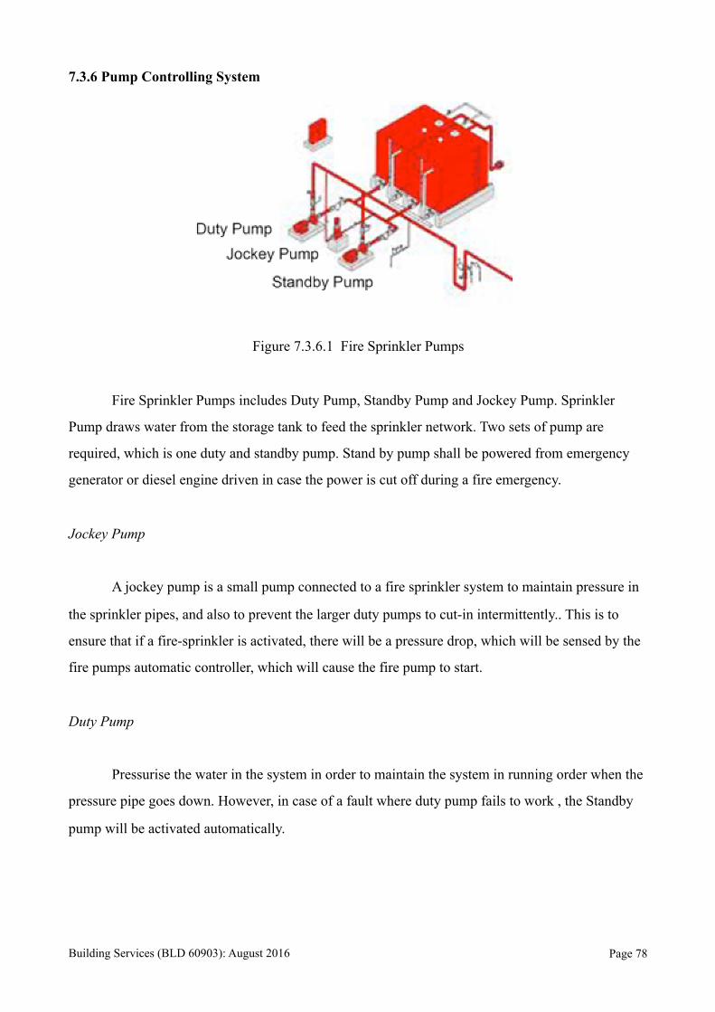
Figure 7.3.5.1 Fire Storage Tank
The water tank stores the water for all the existing sprinklers in the building. The water level
in the water tank must be ensured that there is enough capacity of water inside for emergency usage.
During a fire emergency, when the sprinklers are triggered, water will be transferred from the water
tank to the pumps and the pumps will pressurise the water to all the sprinklers.
UBBL 1984 SECTION 247: Water Storage.
1. Water storage capacity and water flow rate for firefighting systems and installations shall be
provided in accordance with the scale as set out in the Tenth Schedule to these By-laws.
2. Main water storage tanks within the building, other than for hose reel systems, shall be located
at ground, first or second basement levels, with fire brigade pumping inlet connection
accessible to fire appliances.
3. Storage tanks for automatic sprinkler installations where full capacity is provided without need
for replenishment shall be exempted from the restrictions in their location.
Building Services (BLD 60903): August 2016 Page !77
7.3.6 Pump Controlling System
Figure 7.3.6.1 Fire Sprinkler Pumps
Fire Sprinkler Pumps includes Duty Pump, Standby Pump and Jockey Pump. Sprinkler
Pump draws water from the storage tank to feed the sprinkler network. Two sets of pump are
required, which is one duty and standby pump. Stand by pump shall be powered from emergency
generator or diesel engine driven in case the power is cut off during a fire emergency.
Jockey Pump
A jockey pump is a small pump connected to a fire sprinkler system to maintain pressure in
the sprinkler pipes, and also to prevent the larger duty pumps to cut-in intermittently.. This is to
ensure that if a fire-sprinkler is activated, there will be a pressure drop, which will be sensed by the
fire pumps automatic controller, which will cause the fire pump to start.
Duty Pump
Pressurise the water in the system in order to maintain the system in running order when the
pressure pipe goes down. However, in case of a fault where duty pump fails to work , the Standby
pump will be activated automatically.
Building Services (BLD 60903): August 2016 Page !78
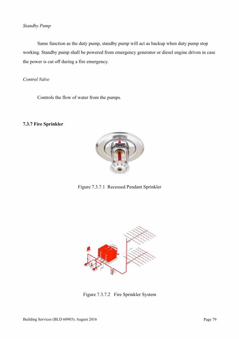
Standby Pump
Same function as the duty pump, standby pump will act as backup when duty pump stop
working. Standby pump shall be powered from emergency generator or diesel engine driven in case
the power is cut off during a fire emergency.
Control Valve
Controls the flow of water from the pumps.
7.3.7 Fire Sprinkler
Figure 7.3.7.1 Recessed Pendant Sprinkler
Figure 7.3.7.2 Fire Sprinkler System
Building Services (BLD 60903): August 2016 Page !79
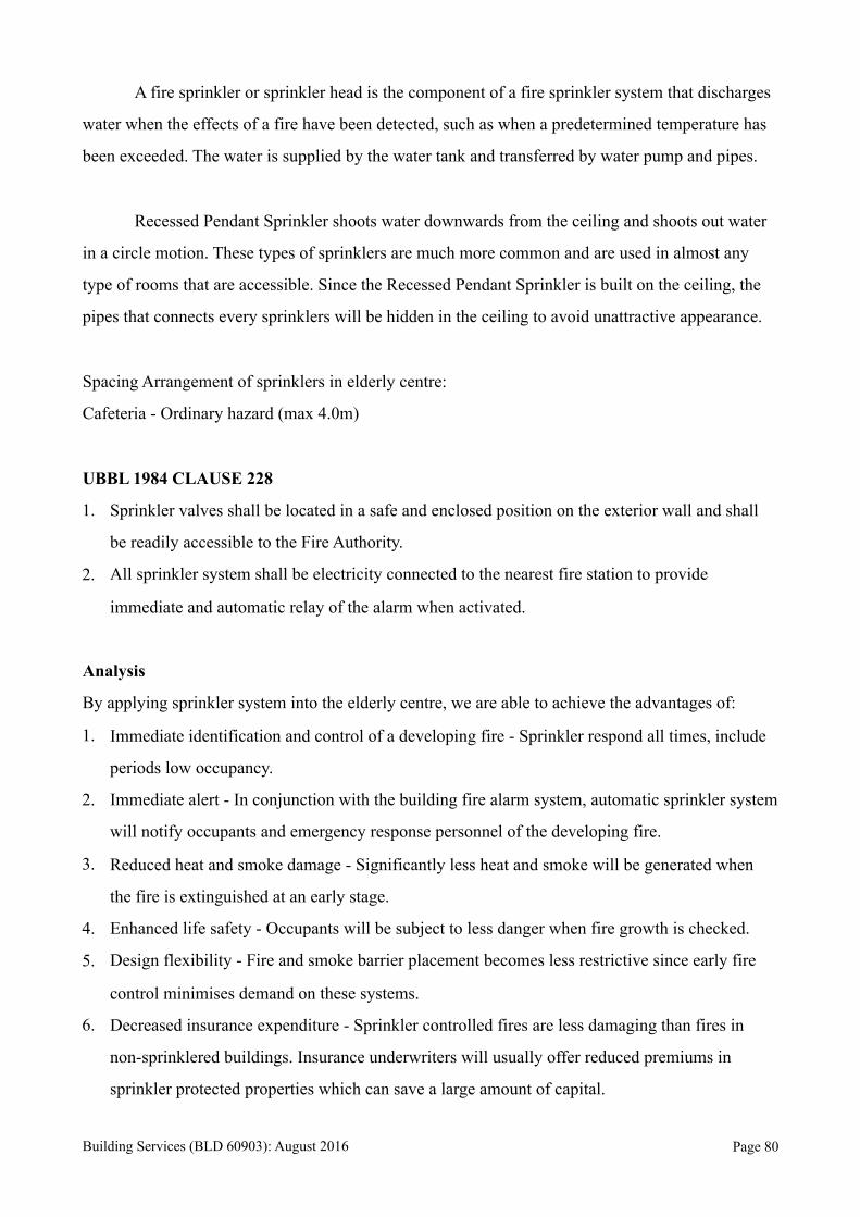
A fire sprinkler or sprinkler head is the component of a fire sprinkler system that discharges
water when the effects of a fire have been detected, such as when a predetermined temperature has
been exceeded. The water is supplied by the water tank and transferred by water pump and pipes.
Recessed Pendant Sprinkler shoots water downwards from the ceiling and shoots out water
in a circle motion. These types of sprinklers are much more common and are used in almost any
type of rooms that are accessible. Since the Recessed Pendant Sprinkler is built on the ceiling, the
pipes that connects every sprinklers will be hidden in the ceiling to avoid unattractive appearance.
Spacing Arrangement of sprinklers in elderly centre:
Cafeteria - Ordinary hazard (max 4.0m)
UBBL 1984 CLAUSE 228
1. Sprinkler valves shall be located in a safe and enclosed position on the exterior wall and shall
be readily accessible to the Fire Authority.
2. All sprinkler system shall be electricity connected to the nearest fire station to provide
immediate and automatic relay of the alarm when activated.
Analysis
By applying sprinkler system into the elderly centre, we are able to achieve the advantages of:
1. Immediate identification and control of a developing fire - Sprinkler respond all times, include
periods low occupancy.
2. Immediate alert - In conjunction with the building fire alarm system, automatic sprinkler system
will notify occupants and emergency response personnel of the developing fire.
3. Reduced heat and smoke damage - Significantly less heat and smoke will be generated when
the fire is extinguished at an early stage.
4. Enhanced life safety - Occupants will be subject to less danger when fire growth is checked.
5. Design flexibility - Fire and smoke barrier placement becomes less restrictive since early fire
control minimises demand on these systems.
6. Decreased insurance expenditure - Sprinkler controlled fires are less damaging than fires in
non-sprinklered buildings. Insurance underwriters will usually offer reduced premiums in
sprinkler protected properties which can save a large amount of capital.
Building Services (BLD 60903): August 2016 Page !80
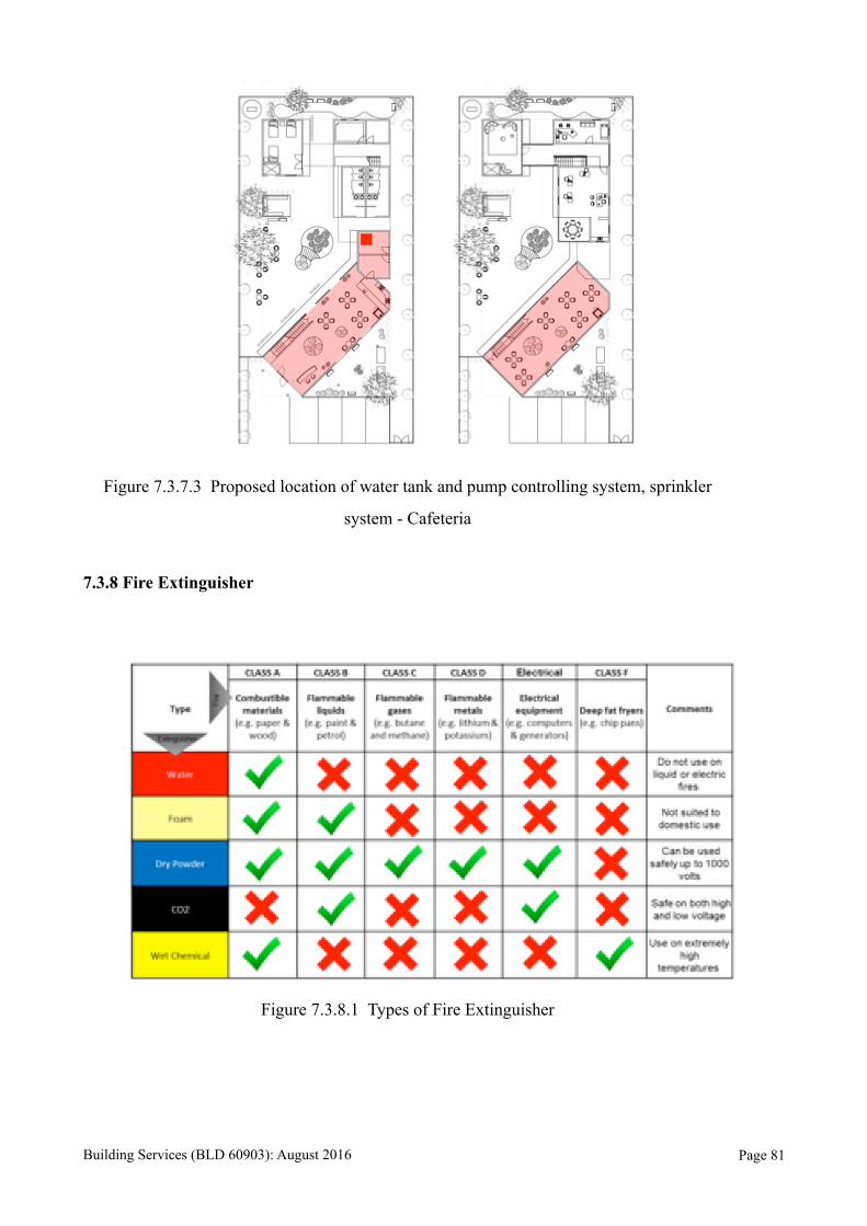
Figure 7.3.7.3 Proposed location of water tank and pump controlling system, sprinkler
system - Cafeteria
7.3.8 Fire Extinguisher
Figure 7.3.8.1 Types of Fire Extinguisher
Building Services (BLD 60903): August 2016 Page !81
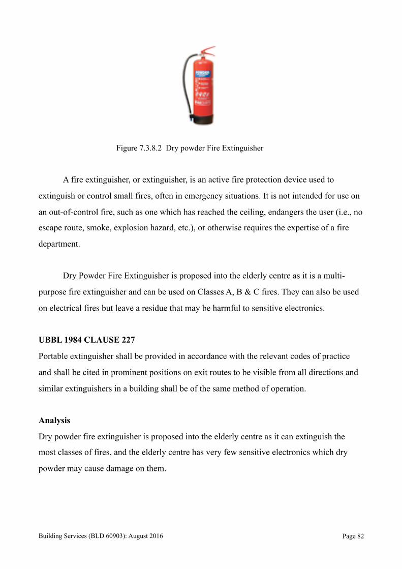
Figure 7.3.8.2 Dry powder Fire Extinguisher
A fire extinguisher, or extinguisher, is an active fire protection device used to
extinguish or control small fires, often in emergency situations. It is not intended for use on
an out-of-control fire, such as one which has reached the ceiling, endangers the user (i.e., no
escape route, smoke, explosion hazard, etc.), or otherwise requires the expertise of a fire
department.
Dry Powder Fire Extinguisher is proposed into the elderly centre as it is a multi-
purpose fire extinguisher and can be used on Classes A, B & C fires. They can also be used
on electrical fires but leave a residue that may be harmful to sensitive electronics.
UBBL 1984 CLAUSE 227
Portable extinguisher shall be provided in accordance with the relevant codes of practice
and shall be cited in prominent positions on exit routes to be visible from all directions and
similar extinguishers in a building shall be of the same method of operation.
Analysis
Dry powder fire extinguisher is proposed into the elderly centre as it can extinguish the
most classes of fires, and the elderly centre has very few sensitive electronics which dry
powder may cause damage on them.
Building Services (BLD 60903): August 2016 Page !82
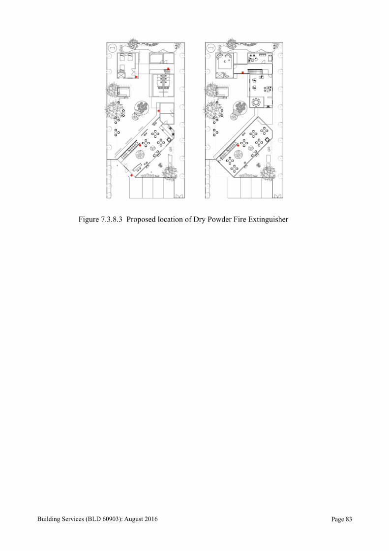
Figure 7.3.8.3 Proposed location of Dry Powder Fire Extinguisher
Building Services (BLD 60903): August 2016 Page !83
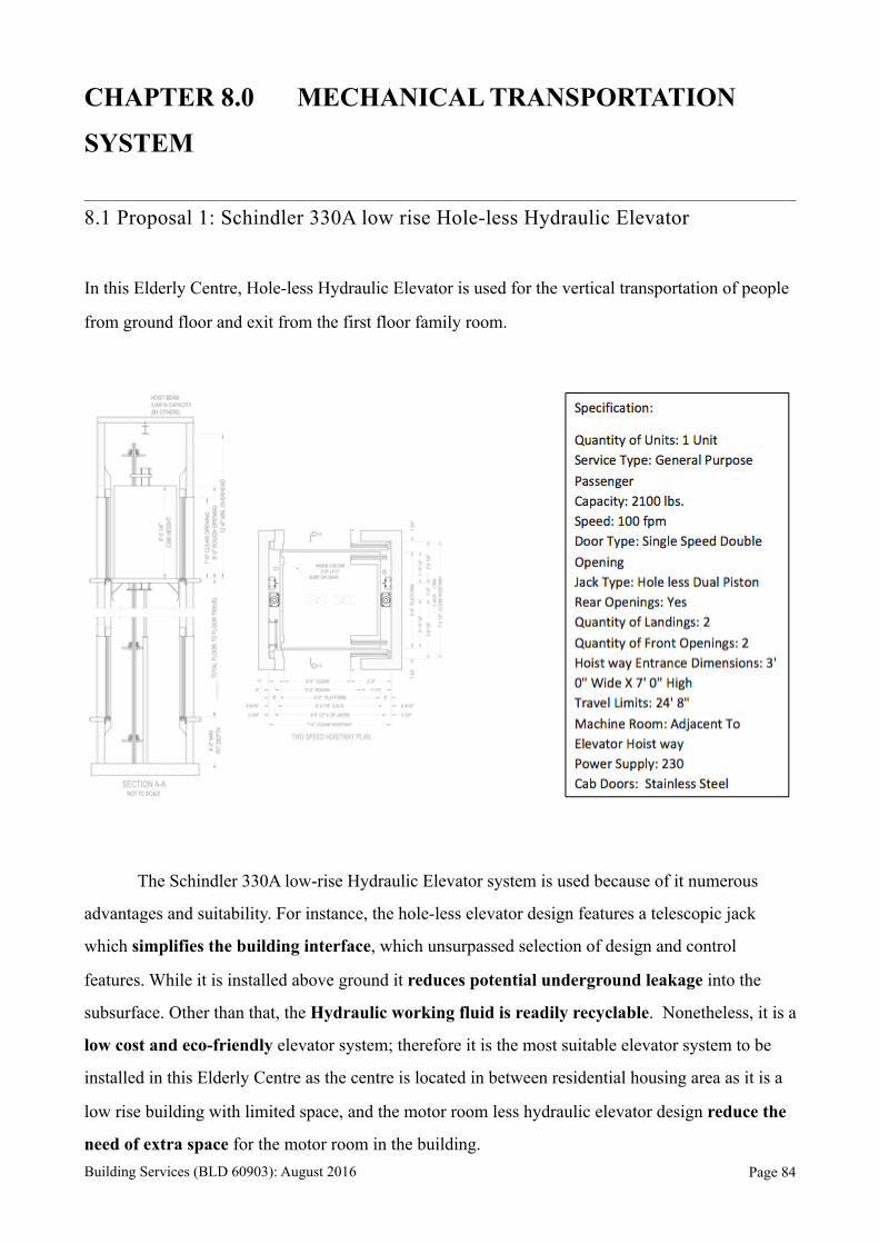
CHAPTER 8.0 MECHANICAL TRANSPORTATION
SYSTEM
8.1 Proposal 1: Schindler 330A low rise Hole-less Hydraulic Elevator
In this Elderly Centre, Hole-less Hydraulic Elevator is used for the vertical transportation of people
from ground floor and exit from the first floor family room.
The Schindler 330A low-rise Hydraulic Elevator system is used because of it numerous
advantages and suitability. For instance, the hole-less elevator design features a telescopic jack
which simplifies the building interface, which unsurpassed selection of design and control
features. While it is installed above ground it reduces potential underground leakage into the
subsurface. Other than that, the Hydraulic working fluid is readily recyclable. Nonetheless, it is a
low cost and eco-friendly elevator system; therefore it is the most suitable elevator system to be
installed in this Elderly Centre as the centre is located in between residential housing area as it is a
low rise building with limited space, and the motor room less hydraulic elevator design reduce the
need of extra space for the motor room in the building. Building Services (BLD 60903): August 2016 Page !84
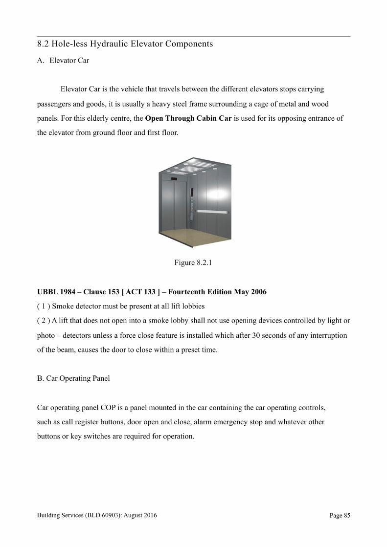
8.2 Hole-less Hydraulic Elevator Components
A. Elevator Car
Elevator Car is the vehicle that travels between the different elevators stops carrying
passengers and goods, it is usually a heavy steel frame surrounding a cage of metal and wood
panels. For this elderly centre, the Open Through Cabin Car is used for its opposing entrance of
the elevator from ground floor and first floor.
Figure 8.2.1
UBBL 1984 – Clause 153 [ ACT 133 ] – Fourteenth Edition May 2006
( 1 ) Smoke detector must be present at all lift lobbies
( 2 ) A lift that does not open into a smoke lobby shall not use opening devices controlled by light or
photo – detectors unless a force close feature is installed which after 30 seconds of any interruption
of the beam, causes the door to close within a preset time.
B. Car Operating Panel
Car operating panel COP is a panel mounted in the car containing the car operating controls,
such as call register buttons, door open and close, alarm emergency stop and whatever other
buttons or key switches are required for operation.
Building Services (BLD 60903): August 2016 Page !85

Figure 8.2.2
C. Emergency Trap Door Assembly
Emergency trap door can be easily opened from inside the car by using triangular key and
from outside the car without a key by turning the link to pull locking arms. Electrical safety
switches that are fixed to the side frame of trap door causes the lift to stop if the locking
ceases to be effective; restoring the lift to service shall only be possible after deliberate
relocking.
Figure 8.2.3
Building Services (BLD 60903): August 2016 Page !86
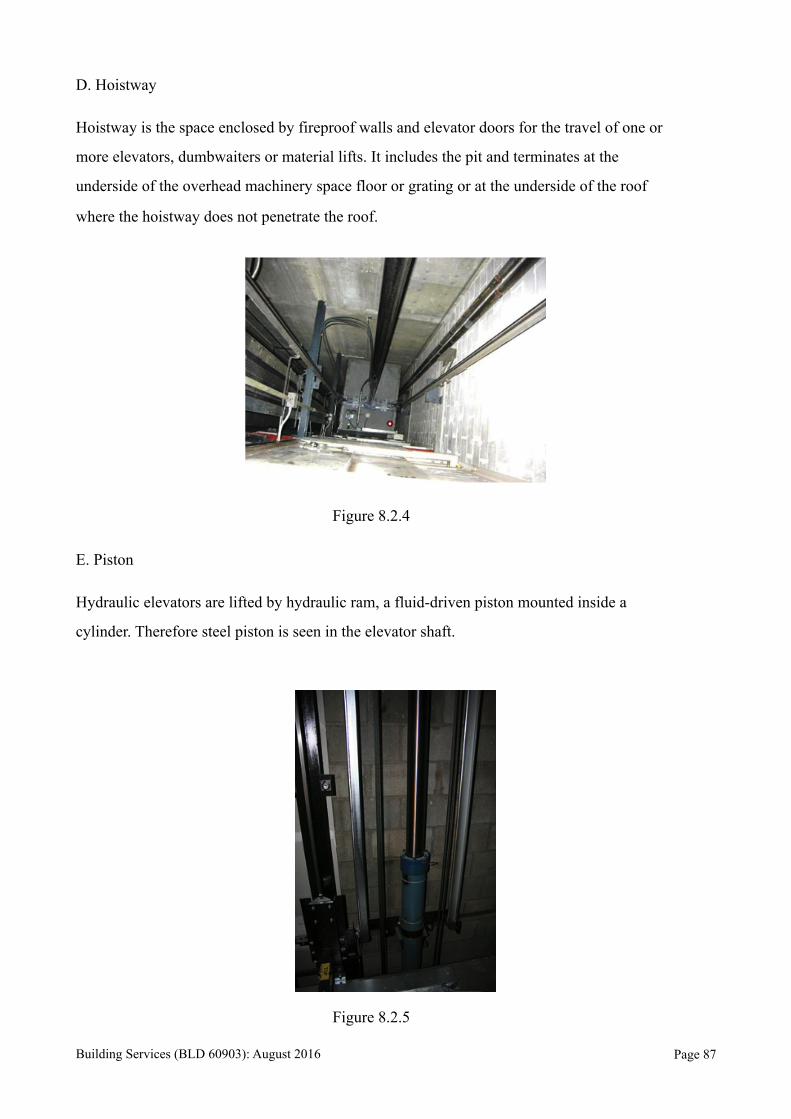
D. Hoistway
Hoistway is the space enclosed by fireproof walls and elevator doors for the travel of one or
more elevators, dumbwaiters or material lifts. It includes the pit and terminates at the
underside of the overhead machinery space floor or grating or at the underside of the roof
where the hoistway does not penetrate the roof.
Figure 8.2.4
E. Piston
Hydraulic elevators are lifted by hydraulic ram, a fluid-driven piston mounted inside a
cylinder. Therefore steel piston is seen in the elevator shaft.
Figure 8.2.5
Building Services (BLD 60903): August 2016 Page !87
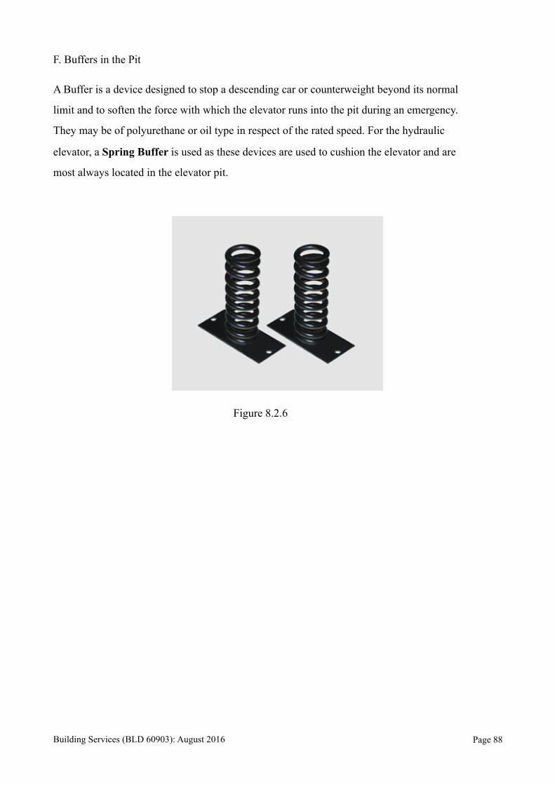
F. Buffers in the Pit
A Buffer is a device designed to stop a descending car or counterweight beyond its normal
limit and to soften the force with which the elevator runs into the pit during an emergency.
They may be of polyurethane or oil type in respect of the rated speed. For the hydraulic
elevator, a Spring Buffer is used as these devices are used to cushion the elevator and are
most always located in the elevator pit.
Figure 8.2.6
Building Services (BLD 60903): August 2016 Page !88
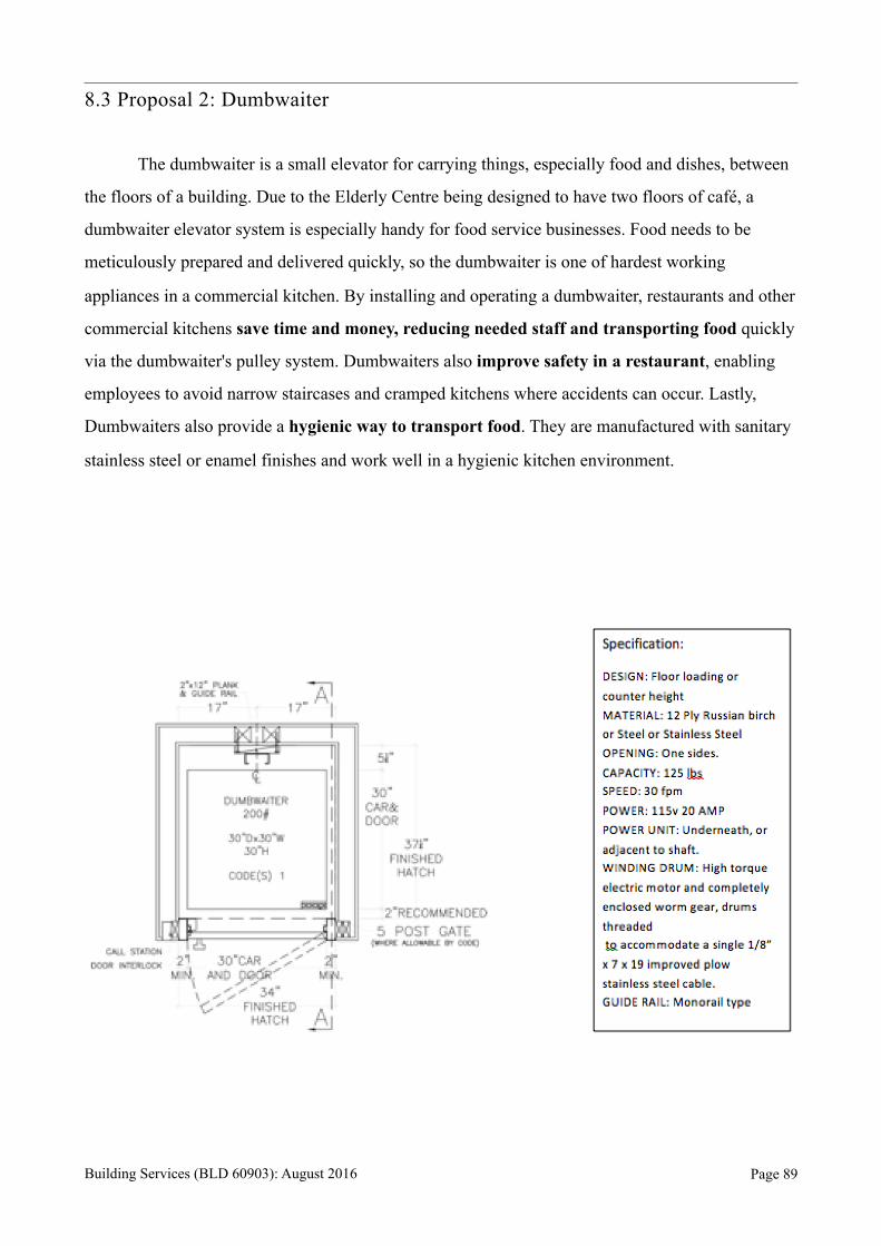
8.3 Proposal 2: Dumbwaiter
The dumbwaiter is a small elevator for carrying things, especially food and dishes, between
the floors of a building. Due to the Elderly Centre being designed to have two floors of café, a
dumbwaiter elevator system is especially handy for food service businesses. Food needs to be
meticulously prepared and delivered quickly, so the dumbwaiter is one of hardest working
appliances in a commercial kitchen. By installing and operating a dumbwaiter, restaurants and other
commercial kitchens save time and money, reducing needed staff and transporting food quickly
via the dumbwaiter's pulley system. Dumbwaiters also improve safety in a restaurant, enabling
employees to avoid narrow staircases and cramped kitchens where accidents can occur. Lastly,
Dumbwaiters also provide a hygienic way to transport food. They are manufactured with sanitary
stainless steel or enamel finishes and work well in a hygienic kitchen environment.
Building Services (BLD 60903): August 2016 Page !89
CHAPTER 9.0 CONCLUSION
Every systems and components must be chosen wisely before conducting or apply it
onto the centre. In this case, undoubtedly, the systems and components must satisfy the
environments and the elderly as this is an elderly community centre. Thus, quality of the
surrounding environment and the quality of user’s life can be assured.
For instance, the mechanical ventilation systems chosen to apply onto the elderly
community centre are appropriate to the conditions and spaces as to generate maximum efficiency
of their functions. Fresh air is one of the critical aspect to be concerned, to ensure the health of the
users and the environment, so, the applied ventilation systems in different locations play an
important role in harmonising this relationship.
Besides, air-conditioning system is applied on certain locations that are necessary in
consideration of the suitability and the environment factors. System using for air-conditioning is
concerned of its advantages compared to others. As there is a limitation on the dimension of site,
units with smaller scale and without plant room are suitable to function efficiently.
In fire protection system, in addition, this public elderly community centre, must be
appointed with care and organised. Routes, equipment, signs and etc. must be chosen and planned
in such secure way to have a clear direction and instruction to ensure users safety when there is an
emergency.
Lastly, in mechanical transportation system, applying on the location where elderly or
users with any disability can access to upper public floor with comfort. System chosen must be
concerned the needs of users and the environment especially in this community centre. Besides, the
design for door openings are in consideration of space saving and the anthropometry of users to
ensure their comfort.
Building Services (BLD 60903): August 2016 Page !90
CHAPTER 10.0 REFERENCES
Balanced Ventilation. (n.d.). Retrieved November 2, 2016, from /react-text http://
www.greenbuildingadvisor.com/green-basics/balanced-ventilation
Types of Ventilation Systems. (n.d.). Retrieved October 28, 2016, from /react-text http://
www.hometips.com/how-it-works/ventilation-systems-exhaust.html
Designing Buildings Wiki The construction industry knowledge base. (n.d.). Retrieved November
10, 2016, from /react-text https://www.designingbuildings.co.uk/wiki/
Mechanical_ventilation_of_buildings
Twin City fans & blowers. (n.d.). Retrieved November 24, 2016, from /react-text http://
www.tcf.com/industries-applications/applications/Elevator-Shaft-Exhaust
Active / passive fire protection. (n.d.). Retrieved from /react-text http://www.hse.gov.uk/comah/
sragtech/techmeasfire.htm
How sprinklers work - Fire Sprinker Initiative. (n.d.). Retrieved from /react-text http://
www.firesprinklerinitiative.org/advocacy-tools/fact-sheets/how-sprinklers-work.aspx
What Are Different Types of Fire Detection Equipment. (n.d.). Retrieved from /react-text http://
www.lumarfireprotection.com/what-are-different-types-of-fire-detection-equipment/
Fire Suppression Systems. (2016). Retrieved from /react-text http://www.conceptfire-uk.com/
Security, P. F. (n.d.). Wet/Dry Riser Systems. Retrieved from /react-text https://www.protec.co.uk/
product-page/sprinklers-and-water-mist/product/product/wet-dry-riser-systems/
Types of Ventilation Systems. (n.d.). Retrieved November 24, 2016, from /react-text http://
www.hometips.com/how-it-works/ventilation-systems-exhaust.html
Building Services (BLD 60903): August 2016 Page !91