dc100 data collector instruction manual · instruction manual dc100 data collector im dc100-01e im...
TRANSCRIPT
InstructionManual
DC100Data Collector
IM DC100-01E
IM DC100-01E6th Edition
1IM DC100-01E
ForewordThank you for purchasing the YOKOGAWA Data Collector DC100.This User’s Manual contains useful information regarding the instrument’s functions andoperating procedures, as well as precautions that should be observed during use. To ensure properuse of the instrument, please read this manual thoroughly before operating the instrument.Keep the manual in a safe place for quick reference whenever a question arises.The following manual is provided with the instrument in addition to this manual.
Manual Name Manual No.
DC100 Communication Interface IMDC100-11EDC100 Viewer Software IMDP15013-61E
Notes• DARWIN is a system comprising a number of data-acquisition equipment components. In the
course of system growth, new models, software, various input/output modules and optionalfeatures are added to the family to enhance the systems expandability and flexibility. You cancheck the versions of your equipment and software by referring to the style number (Sn) andrelease number (Rn) respectively which are shown on the nameplate of the main unit.When configuring a system, you must confirm that the style number of each component unit andsoftware meets the following requirements:1 the style number of each input/output module must be the same as or lower than that of the
main unit or subunit to which the module is connected.2 the release number of a dedicated software package must be the same or higher than the style
number of the main unit or subunit where the package is installed and where it performscontrol.
Any equipment/software not meeting these requirements might have incompatible areas withyour system configuration.
In this manual, equipment of style S8 is explained.
For unsupported functions as classified by the style number, see the next page.• The contents of this manual are subject to change without prior notice as a result of
improvements in the instrument’s performance and functions.• Every effort has been made in the preparation of this manual to ensure the accuracy of its
contents. However, should you have any questions or find any errors, please contact yournearest YOKOGAWA representative as listed on the back cover of this manual.
• Copying or reproduction of all or any part of the contents of this manual withoutYOKOGAWA’s permission is strictly prohibited.
TrademarksDOS and Windows are registered trademarks of Microsoft Corporation.IBM is a registered trademark of International Business Machines Corporation.
Revisions1st Edition: July 19972nd Edition: November 19973rd Edition: January 19984th Edition: November 19985th Edition: June 20006th Edition: October 2000
Disk No. RE11
6th Edition: October 2000 (YK)
All Rights Reserved, Copyright 1997 Yokogawa Electric Corporation

2 IM DC100-01E
Unsupported Functions As Classified by the Style NumberProducts with style numbers S1 to S5, and S9 are not sold.The following functions are available for DC100 with style number S7:• Report function (/M3, optional)• SCSI interface (/C5, optional)• Flag function in computation function (/M1, optional)• Group reset function in computation function (/M1, optional)The following functions are available for DC100 with style number S8:• Ethernet module• Digital input module• Measurement of active power and apparent power on ch3 to ch6 for power monitor moduleThe following function is available for DC100 with style number S10:• Retransmission module
3IM DC100-01E
Checking the Contents of the Package
Unpack the box and check the contents before operating the instrument. In case the wronginstrument or accessories have been delivered, or if some accessories are not present, or if theyseem abnormal, contact the dealer from which you purchased them. Furthermore, please contact aYokogawa representative to order any of parts as follows.
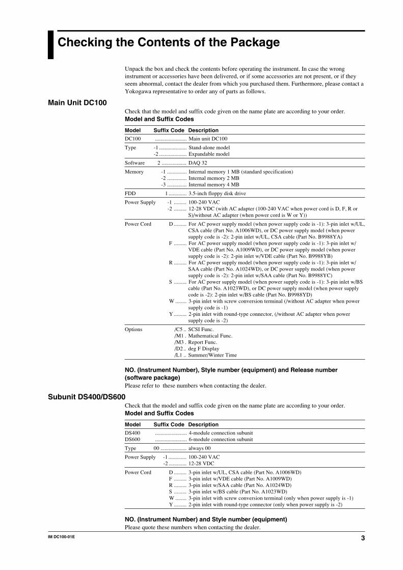
Main Unit DC100Check that the model and suffix code given on the name plate are according to your order.Model and Suffix Codes
Model Suffix Code Description
DC100 ....................... Main unit DC100
Type -1 .................... Stand-alone model-2 .................... Expandable model
Software 2 .................. DAQ 32
Memory -1 .............. Internal memory 1 MB (standard specification)-2 .............. Internal memory 2 MB-3 .............. Internal memory 4 MB
FDD 1 ............. 3.5-inch floppy disk drive
Power Supply -1 ......... 100-240 VAC -2 ......... 12-28 VDC (with AC adapter (100-240 VAC when power cord is D, F, R or
S)/without AC adapter (when power cord is W or Y))
Power Cord D ......... For AC power supply model (when power supply code is -1): 3-pin inlet w/UL,CSA cable (Part No. A1006WD), or DC power supply model (when powersupply code is -2): 2-pin inlet w/UL, CSA cable (Part No. B9988YA)
F ......... For AC power supply model (when power supply code is -1): 3-pin inlet w/VDE cable (Part No. A1009WD), or DC power supply model (when powersupply code is -2): 2-pin inlet w/VDE cable (Part No. B9988YB)
R ......... For AC power supply model (when power supply code is -1): 3-pin inlet w/SAA cable (Part No. A1024WD), or DC power supply model (when powersupply code is -2): 2-pin inlet w/SAA cable (Part No. B9988YC)
S ......... For AC power supply model (when power supply code is -1): 3-pin inlet w/BScable (Part No. A1023WD), or DC power supply model (when power supplycode is -2): 2-pin inlet w/BS cable (Part No. B9988YD)
W ........ 3-pin inlet with screw conversion terminal (/without AC adapter when powersupply code is -1)
Y ......... 2-pin inlet with round-type connector, (/without AC adapter when powersupply code is -2)
Options /C5 .. SCSI Func. /M1 . Mathematical Func. /M3 . Report Func. /D2 .. deg F Display /L1 .. Summer/Winter Time
NO. (Instrument Number), Style number (equipment) and Release number(software package)Please refer to these numbers when contacting the dealer.
Subunit DS400/DS600Check that the model and suffix code given on the name plate are according to your order.Model and Suffix Codes
Model Suffix Code Description
DS400 ....................... 4-module connection subunitDS600 ....................... 6-module connection subunit
Type 00 ................... always 00
Power Supply -1 ............. 100-240 VAC-2 ............. 12-28 VDC
Power Cord D ......... 3-pin inlet w/UL, CSA cable (Part No. A1006WD)F ......... 3-pin inlet w/VDE cable (Part No. A1009WD)R ......... 3-pin inlet w/SAA cable (Part No. A1024WD)S ......... 3-pin inlet w/BS cable (Part No. A1023WD)W ........ 3-pin inlet with screw conversion terminal (only when power supply is -1)Y ......... 2-pin inlet with round-type connector (only when power supply is -2)
NO. (Instrument Number) and Style number (equipment)Please quote these numbers when contacting the dealer.
4 IM DC100-01E
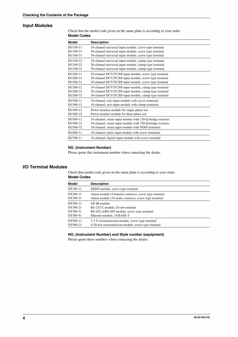
Input ModulesCheck that the model code given on the name plate is according to your order.Model Codes
Model Description
DU100-11 10-channel universal input module, screw type terminalDU100-21 20-channel universal input module, screw type terminalDU100-31 30-channel universal input module, screw type terminal
DU100-12 10-channel universal input module, clamp type terminalDU100-22 20-channel universal input module, clamp type terminalDU100-32 30-channel universal input module, clamp type terminal
DU200-11 10-channel DCV/TC/DI input module, screw type terminalDU200-21 20-channel DCV/TC/DI input module, screw type terminalDU200-31 30-channel DCV/TC/DI input module, screw type terminal
DU200-12 10-channel DCV/TC/DI input module, clamp type terminalDU200-22 20-channel DCV/TC/DI input module, clamp type terminalDU200-32 30-channel DCV/TC/DI input module, clamp type terminal
DU300-11 10-channel, mA-input module with screw terminalsDU300-12 10-channel, mA-input module with clamp terminals
DU400-12 Power monitor module for single-phase useDU400-22 Power monitor module for three-phase use
DU500-12 10-channel, strain input module with 120-Ω bridge resistorsDU500-22 10-channel, strain input module with 350-Ω bridge resistorsDU500-32 10-channel, strain input module with NDIS terminals
DU600-11 10-channel, pulse input module with screw terminals
DU700-11 10-channel, digital input module with screw terminal
NO. (Instrument Number)Please quote this instrument number when contacting the dealer.
I/O Terminal ModulesCheck that model code given on the name plate is according to your order.Model Codes
Model Description
DT100-11 DI/DO module, screw type terminal
DT200-11 Alarm module (4 transfer contacts), screw type terminalDT200-21 Alarm module (10 make contacts), screw type terminal
DT300-11 GP-IB moduleDT300-21 RS-232-C module, D-sub terminalDT300-31 RS-422-A/RS-485 module, screw type terminalDT300-41 Ethernet module, 10 BASE-T
DT500-11 1-5 V retransmission module, screw type terminalDT500-21 4-20 mA retransmission module, screw type terminal
NO. (Instrument Number) and Style number (equipment)Please quote these numbers when contacting the dealer.
Checking the Contents of the Package
5IM DC100-01E
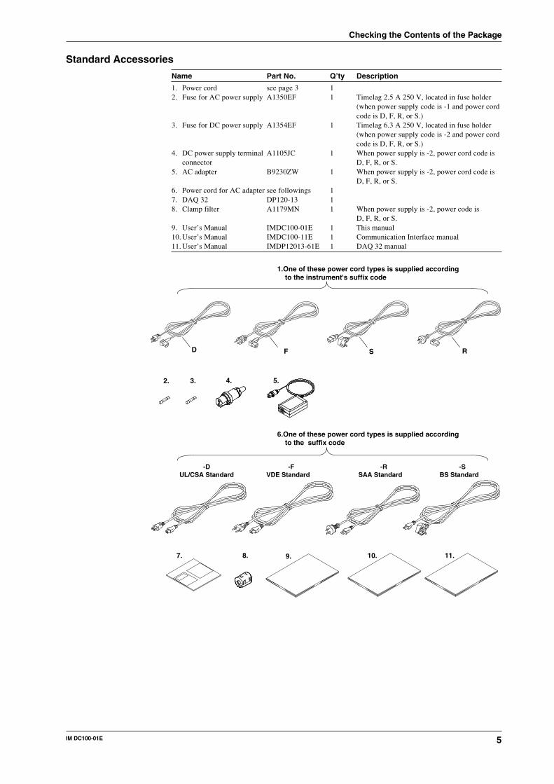
Standard Accessories
Name Part No. Q’ty Description
1. Power cord see page 3 12. Fuse for AC power supply A1350EF 1 Timelag 2.5 A 250 V, located in fuse holder
(when power supply code is -1 and power cordcode is D, F, R, or S.)
3. Fuse for DC power supply A1354EF 1 Timelag 6.3 A 250 V, located in fuse holder(when power supply code is -2 and power cordcode is D, F, R, or S.)
4. DC power supply terminal A1105JC 1 When power supply is -2, power cord code isconnector D, F, R, or S.
5. AC adapter B9230ZW 1 When power supply is -2, power cord code isD, F, R, or S.
6. Power cord for AC adapter see followings 17. DAQ 32 DP120-13 18. Clamp filter A1179MN 1 When power supply is -2, power code is
D, F, R, or S.9. User’s Manual IMDC100-01E 1 This manual10. User’s Manual IMDC100-11E 1 Communication Interface manual11. User’s Manual IMDP12013-61E 1 DAQ 32 manual
1.One of these power cord types is supplied according to the instrument's suffix code
6.One of these power cord types is supplied according to the suffix code
FD S R
2. 3. 4. 5.
7. 9. 10. 11.
-DUL/CSA Standard
-FVDE Standard
-SBS Standard
-RSAA Standard
8.
Checking the Contents of the Package
6 IM DC100-01E
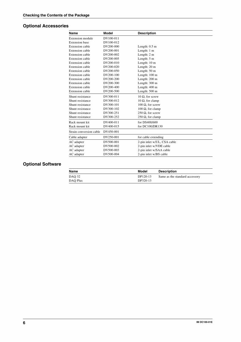
Optional Accessories
Name Model Description
Extension module DV100-011Extension base DV100-012Extension cable DV200-000 Length: 0.5 mExtension cable DV200-001 Length: 1 mExtension cable DV200-002 Length: 2 mExtension cable DV200-005 Length: 5 mExtension cable DV200-010 Length: 10 mExtension cable DV200-020 Length: 20 mExtension cable DV200-050 Length: 50 mExtension cable DV200-100 Length: 100 mExtension cable DV200-200 Length: 200 mExtension cable DV200-300 Length: 300 mExtension cable DV200-400 Length: 400 mExtension cable DV200-500 Length: 500 m
Shunt resistance DV300-011 10 Ω, for screwShunt resistance DV300-012 10 Ω, for clampShunt resistance DV300-101 100 Ω, for screwShunt resistance DV300-102 100 Ω, for clampShunt resistance DV300-251 250 Ω, for screwShunt resistance DV300-252 250 Ω, for clamp
Rack mount kit DV400-011 for DS400/600Rack mount kit DV400-015 for DC100/DR130
Strain conversion cable DV450-001
Cable adapter DV250-001 for cable extending
AC adapter DV500-001 2-pin inlet w/UL, CSA cableAC adapter DV500-002 2-pin inlet w/VDE cableAC adapter DV500-003 2-pin inlet w/SAA cableAC adapter DV500-004 2-pin inlet w/BS cable
Optional Software
Name Model Description
DAQ 32 DP120-13 Same as the standard accessoryDAQ Plus DP320-13
Checking the Contents of the Package
7IM DC100-01E
Safety Precautions
This instrument is an IEC safety class I instrument (provided with terminal for protectivegrounding).The following general safety precautions must be observed during all phases of operation, serviceand repair of this instrument. If this instrument is used in a manner not sepecified in this manual,the protection provided by this instrument may be impaired. Also, YOKOGAWA ElectricCorporation assumes no liability for the customer’s failure to comply with these requirements.
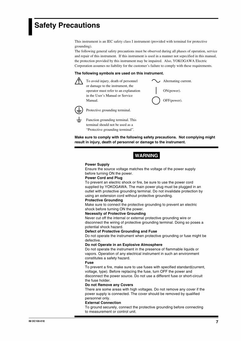
The following symbols are used on this instrument.
To avoid injury, death of personnelor damage to the instrument, theoperator must refer to an explanationin the User’s Manual or ServiceManual.
Protective grounding terminal.
Function grounding terminal. Thisterminal should not be used as a“Protective grounding terminal”.
Alternating current.
ON(power).
OFF(power).
Make sure to comply with the following safety precautions. Not complying mightresult in injury, death of personnel or damage to the instrument.
WARNING
Power SupplyEnsure the source voltage matches the voltage of the power supplybefore turning ON the power.Power Cord and PlugTo prevent an electric shock or fire, be sure to use the power cordsupplied by YOKOGAWA. The main power plug must be plugged in anoutlet with protective grounding terminal. Do not invalidate protection byusing an extension cord without protective grounding.Protective GroundingMake sure to connect the protective grounding to prevent an electricshock before turning ON the power.Necessity of Protective GroundingNever cut off the internal or external protective grounding wire ordisconnect the wiring of protective grounding terminal. Doing so poses apotential shock hazard.Defect of Protective Grounding and FuseDo not operate the instrument when protective grounding or fuse might bedefective.Do not Operate in an Explosive AtmosphereDo not operate the instrument in the presence of flammable liquids orvapors. Operation of any electrical instrument in such an environmentconstitutes a safety hazard.FuseTo prevent a fire, make sure to use fuses with specified standard(current,voltage, type). Before replacing the fuse, turn OFF the power anddisconnect the power source. Do not use a different fuse or short-circuitthe fuse holder.Do not Remove any CoversThere are some areas with high voltages. Do not remove any cover if thepower supply is connected. The cover should be removed by qualifiedpersonnel only.External ConnectionTo ground securely, connect the protective grounding before connectingto measurement or control unit.
8 IM DC100-01E
How to Use this Manual
This User’s Manual consists of the following fourteen chapters and Index.
Chapter Title DescriptionChapter 1 System Configuration Explains the position of the DC within DARWIN, its
configuration, etc..
Chapter 2 Functions Explains the functions of the DC. Operatingprocedures are not explained here.
Chapter 3 Installation and Wiring Describes cautions for use, explains how to install andwire the DC, the power cord, how to switch ON/OFFthe DC, how to structure system modules, how to setthe date/time, explains the noise filter, etc..
Chapter 4 Setting the Monitor Mode Explains the display in the monitor mode.Display
Chapter 5 Setting the Input Type/ Explains the operations when setting the input type,Span/Linear Scaling span and linear scaling function.
Chapter 6 Writing Measured or Explains the operations when writing measured orComputed Data computed data on the built-in RAM disk and the
setting procedure for the writing action.
Chapter 7 Working With Measured or Explains the procedure for copying measured orComputed Data File computed data onto a floppy disk, display of directory
or file information, file deletion in the RAM disk, andRAM disk initialization.
Chapter 8 Executing Alarm Setting or Explains how to set an alarm and how to do when anDisplay and Other Settings alarm occurs.
Chapter 9 Event/Action Function and Explains how to operate the event/action function,Other Functions how to copy channel information, how to reset alarms,
how to reset the timer, how to use the key-lock, andhow to use the external input/output function.
Chapter 10 Basic Settings (SET UP) Explains functions which usually do not need to bechanged, and how to set basic functions.
Chapter 11 Working With a File in SET Explains the operations for saving or reading dataMode or SETUP Mode settings, file deletion, and floppy disk formatting.
Chapter 12 Executing Computation Explains the computation function (optional).(Available with the /M1 Model)
Chapter 13 Trouble-Shooting and Explains maintenance procedures, error messages andMaintenance calibration procedures.
Chapter 14 Specifications Explains specifications for all features of DC.
Index Gives the index in main menu and alphabetic order.
9IM DC100-01E
Conventions Used in this Manual
Used SymbolsThe following symbol marks are used to attract the operator’s attention.
Affixed to the DC100, indicating that for safety, the operator should referto the appropriate User’s Manual. For a list of the User’s Manuals, referto page 1.
Describes precautions that should be observed to prevent the danger ofinjury or death to the user.
Describes precautions that should be observed to prevent damage to theDC100.
Note Provides information that is important for proper operation of the DC100.
Indicates the relevant panel keys and indicators to carry ou the operation
The procedure is explained by a flow diagram. For th meaning of each operation, refer to the example below. Th operating procedures are given with the assumption that yo are not familiar with the operation. Thus, it may not b necessary to carry out all the steps when changing settings
Describes settings and restrictions relating to the operation
10 IM DC100-01E
Contents
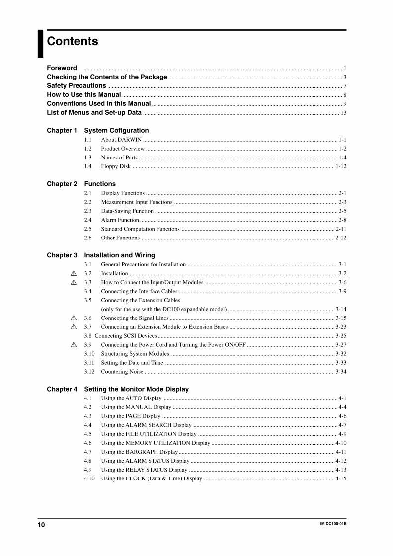
Foreword ............................................................................................................................................................................. 1
Checking the Contents of the Package ..................................................................................................................... 3
Safety Precautions .............................................................................................................................................................. 7
How to Use this Manual .................................................................................................................................................... 8
Conventions Used in this Manual ................................................................................................................................ 9
List of Menus and Set-up Data .................................................................................................................................... 13
Chapter 1 System Cofiguration1.1 About DARWIN ................................................................................................................................... 1-1
1.2 Product Overview ................................................................................................................................. 1-2
1.3 Names of Parts ...................................................................................................................................... 1-4
1.4 Floppy Disk ........................................................................................................................................ 1-12
Chapter 2 Functions2.1 Display Functions ................................................................................................................................. 2-1
2.2 Measurement Input Functions .............................................................................................................. 2-3
2.3 Data-Saving Function ........................................................................................................................... 2-5
2.4 Alarm Function ..................................................................................................................................... 2-8
2.5 Standard Computation Functions ....................................................................................................... 2-11
2.6 Other Functions .................................................................................................................................. 2-12
Chapter 3 Installation and Wiring3.1 General Precautions for Installation ..................................................................................................... 3-1
3.2 Installation ............................................................................................................................................ 3-2
3.3 How to Connect the Input/Output Modules ......................................................................................... 3-6
3.4 Connecting the Interface Cables ........................................................................................................... 3-9
3.5 Connecting the Extension Cables
(only for the use with the DC100 expandable model) ........................................................................ 3-14
3.6 Connecting the Signal Lines ............................................................................................................... 3-15
3.7 Connecting an Extension Module to Extension Bases ....................................................................... 3-23
3.8 Connecting SCSI Devices ....................................................................................................................... 3-25
3.9 Connecting the Power Cord and Turning the Power ON/OFF ........................................................... 3-27
3.10 Structuring System Modules .............................................................................................................. 3-32
3.11 Setting the Date and Time .................................................................................................................. 3-33
3.12 Countering Noise ................................................................................................................................ 3-34
Chapter 4 Setting the Monitor Mode Display4.1 Using the AUTO Display ..................................................................................................................... 4-1
4.2 Using the MANUAL Display ............................................................................................................... 4-4
4.3 Using the PAGE Display ...................................................................................................................... 4-6
4.4 Using the ALARM SEARCH Display ................................................................................................. 4-7
4.5 Using the FILE UTILIZATION Display .............................................................................................. 4-9
4.6 Using the MEMORY UTILIZATION Display ................................................................................... 4-10
4.7 Using the BARGRAPH Display ......................................................................................................... 4-11
4.8 Using the ALARM STATUS Display ................................................................................................. 4-12
4.9 Using the RELAY STATUS Display .................................................................................................. 4-13
4.10 Using the CLOCK (Data & Time) Display ........................................................................................ 4-15
11IM DC100-01E
Contents
1
2
3
4
5
6
7
8
9
10
11
12
13
14
Index
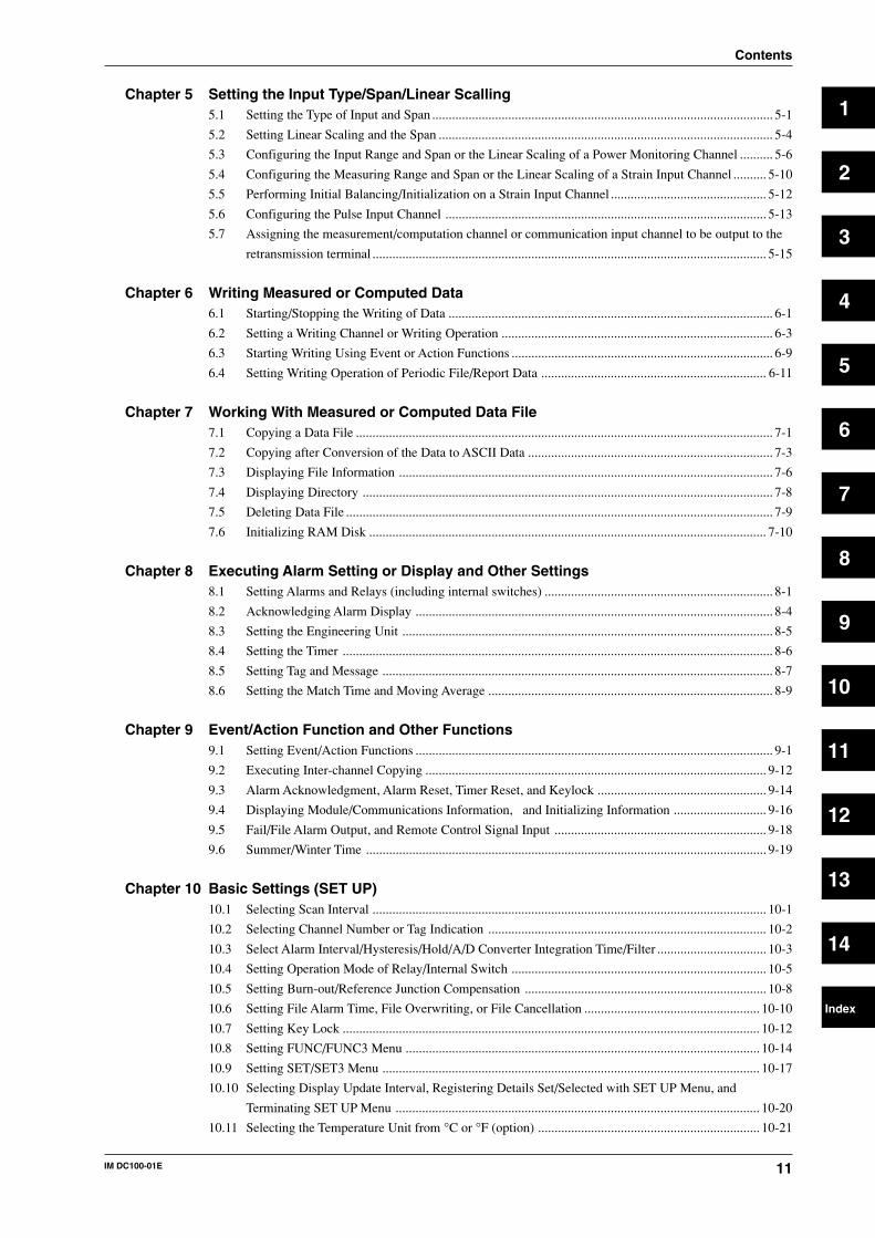
Chapter 5 Setting the Input Type/Span/Linear Scalling5.1 Setting the Type of Input and Span ....................................................................................................... 5-1
5.2 Setting Linear Scaling and the Span ..................................................................................................... 5-4
5.3 Configuring the Input Range and Span or the Linear Scaling of a Power Monitoring Channel .......... 5-6
5.4 Configuring the Measuring Range and Span or the Linear Scaling of a Strain Input Channel .......... 5-10
5.5 Performing Initial Balancing/Initialization on a Strain Input Channel ............................................... 5-12
5.6 Configuring the Pulse Input Channel ................................................................................................. 5-13
5.7 Assigning the measurement/computation channel or communication input channel to be output to the
retransmission terminal ....................................................................................................................... 5-15
Chapter 6 Writing Measured or Computed Data6.1 Starting/Stopping the Writing of Data .................................................................................................. 6-1
6.2 Setting a Writing Channel or Writing Operation .................................................................................. 6-3
6.3 Starting Writing Using Event or Action Functions ............................................................................... 6-9
6.4 Setting Writing Operation of Periodic File/Report Data .................................................................... 6-11
Chapter 7 Working With Measured or Computed Data File7.1 Copying a Data File .............................................................................................................................. 7-1
7.2 Copying after Conversion of the Data to ASCII Data .......................................................................... 7-3
7.3 Displaying File Information ................................................................................................................. 7-6
7.4 Displaying Directory ............................................................................................................................ 7-8
7.5 Deleting Data File ................................................................................................................................. 7-9
7.6 Initializing RAM Disk ........................................................................................................................ 7-10
Chapter 8 Executing Alarm Setting or Display and Other Settings8.1 Setting Alarms and Relays (including internal switches) ..................................................................... 8-1
8.2 Acknowledging Alarm Display ............................................................................................................ 8-4
8.3 Setting the Engineering Unit ................................................................................................................ 8-5
8.4 Setting the Timer .................................................................................................................................. 8-6
8.5 Setting Tag and Message ...................................................................................................................... 8-7
8.6 Setting the Match Time and Moving Average ...................................................................................... 8-9
Chapter 9 Event/Action Function and Other Functions9.1 Setting Event/Action Functions ............................................................................................................ 9-1
9.2 Executing Inter-channel Copying ....................................................................................................... 9-12
9.3 Alarm Acknowledgment, Alarm Reset, Timer Reset, and Keylock ................................................... 9-14
9.4 Displaying Module/Communications Information, and Initializing Information ............................ 9-16
9.5 Fail/File Alarm Output, and Remote Control Signal Input ................................................................ 9-18
9.6 Summer/Winter Time ......................................................................................................................... 9-19
Chapter 10 Basic Settings (SET UP)10.1 Selecting Scan Interval ....................................................................................................................... 10-1
10.2 Selecting Channel Number or Tag Indication .................................................................................... 10-2
10.3 Select Alarm Interval/Hysteresis/Hold/A/D Converter Integration Time/Filter ................................. 10-3
10.4 Setting Operation Mode of Relay/Internal Switch ............................................................................. 10-5
10.5 Setting Burn-out/Reference Junction Compensation ......................................................................... 10-8
10.6 Setting File Alarm Time, File Overwriting, or File Cancellation ..................................................... 10-10
10.7 Setting Key Lock .............................................................................................................................. 10-12
10.8 Setting FUNC/FUNC3 Menu ........................................................................................................... 10-14
10.9 Setting SET/SET3 Menu .................................................................................................................. 10-17
10.10 Selecting Display Update Interval, Registering Details Set/Selected with SET UP Menu, and
Terminating SET UP Menu .............................................................................................................. 10-20
10.11 Selecting the Temperature Unit from °C or °F (option) ................................................................... 10-21
12 IM DC100-01E
Contents
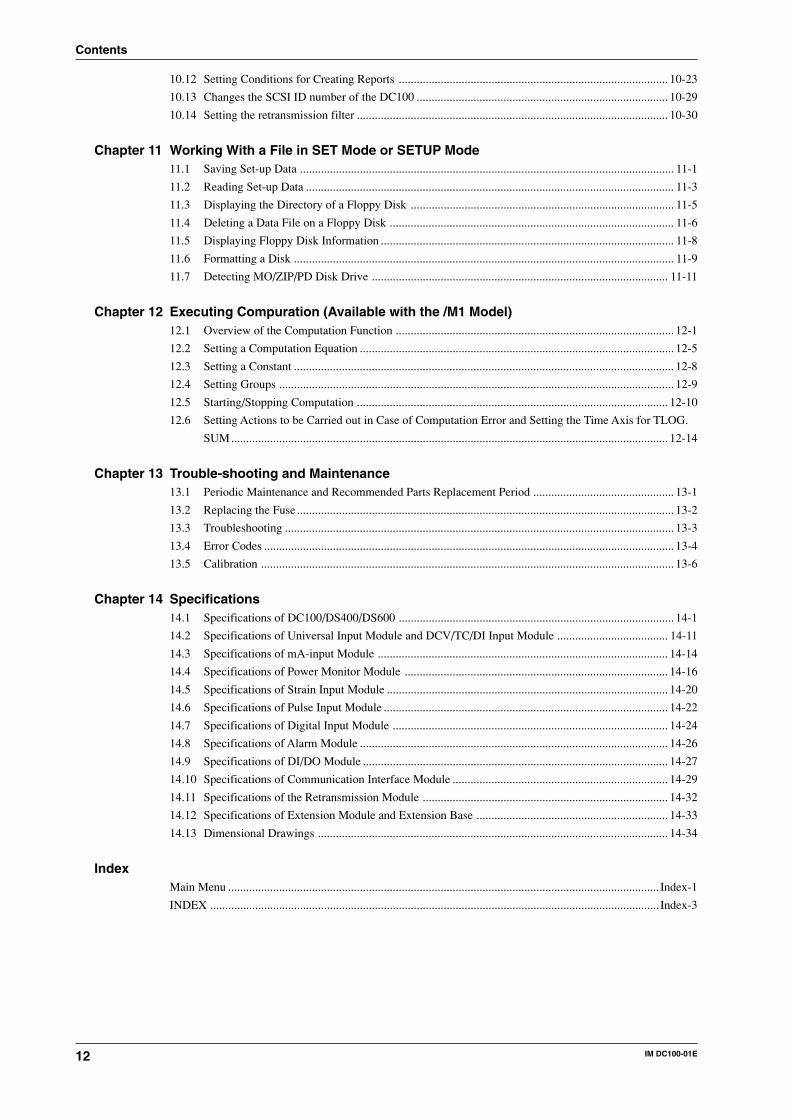
10.12 Setting Conditions for Creating Reports .......................................................................................... 10-23
10.13 Changes the SCSI ID number of the DC100 .................................................................................... 10-29
10.14 Setting the retransmission filter ........................................................................................................ 10-30
Chapter 11 Working With a File in SET Mode or SETUP Mode11.1 Saving Set-up Data ............................................................................................................................. 11-1
11.2 Reading Set-up Data ........................................................................................................................... 11-3
11.3 Displaying the Directory of a Floppy Disk ........................................................................................ 11-5
11.4 Deleting a Data File on a Floppy Disk ............................................................................................... 11-6
11.5 Displaying Floppy Disk Information .................................................................................................. 11-8
11.6 Formatting a Disk ............................................................................................................................... 11-9
11.7 Detecting MO/ZIP/PD Disk Drive ................................................................................................... 11-11
Chapter 12 Executing Compuration (Available with the /M1 Model)12.1 Overview of the Computation Function ............................................................................................. 12-1
12.2 Setting a Computation Equation ......................................................................................................... 12-5
12.3 Setting a Constant ............................................................................................................................... 12-8
12.4 Setting Groups .................................................................................................................................... 12-9
12.5 Starting/Stopping Computation ........................................................................................................ 12-10
12.6 Setting Actions to be Carried out in Case of Computation Error and Setting the Time Axis for TLOG.
SUM .................................................................................................................................................. 12-14
Chapter 13 Trouble-shooting and Maintenance13.1 Periodic Maintenance and Recommended Parts Replacement Period ............................................... 13-1
13.2 Replacing the Fuse .............................................................................................................................. 13-2
13.3 Troubleshooting .................................................................................................................................. 13-3
13.4 Error Codes ......................................................................................................................................... 13-4
13.5 Calibration .......................................................................................................................................... 13-6
Chapter 14 Specifications14.1 Specifications of DC100/DS400/DS600 ............................................................................................ 14-1
14.2 Specifications of Universal Input Module and DCV/TC/DI Input Module ..................................... 14-11
14.3 Specifications of mA-input Module ................................................................................................. 14-14
14.4 Specifications of Power Monitor Module ........................................................................................ 14-16
14.5 Specifications of Strain Input Module .............................................................................................. 14-20
14.6 Specifications of Pulse Input Module ............................................................................................... 14-22
14.7 Specifications of Digital Input Module ............................................................................................ 14-24
14.8 Specifications of Alarm Module ....................................................................................................... 14-26
14.9 Specifications of DI/DO Module ...................................................................................................... 14-27
14.10 Specifications of Communication Interface Module ........................................................................ 14-29
14.11 Specifications of the Retransmission Module .................................................................................. 14-32
14.12 Specifications of Extension Module and Extension Base ................................................................ 14-33
14.13 Dimensional Drawings ..................................................................................................................... 14-34
IndexMain Menu ................................................................................................................................................ Index-1
INDEX ...................................................................................................................................................... Index-3
13IM DC100-01E
List of Menus and Set-up Data
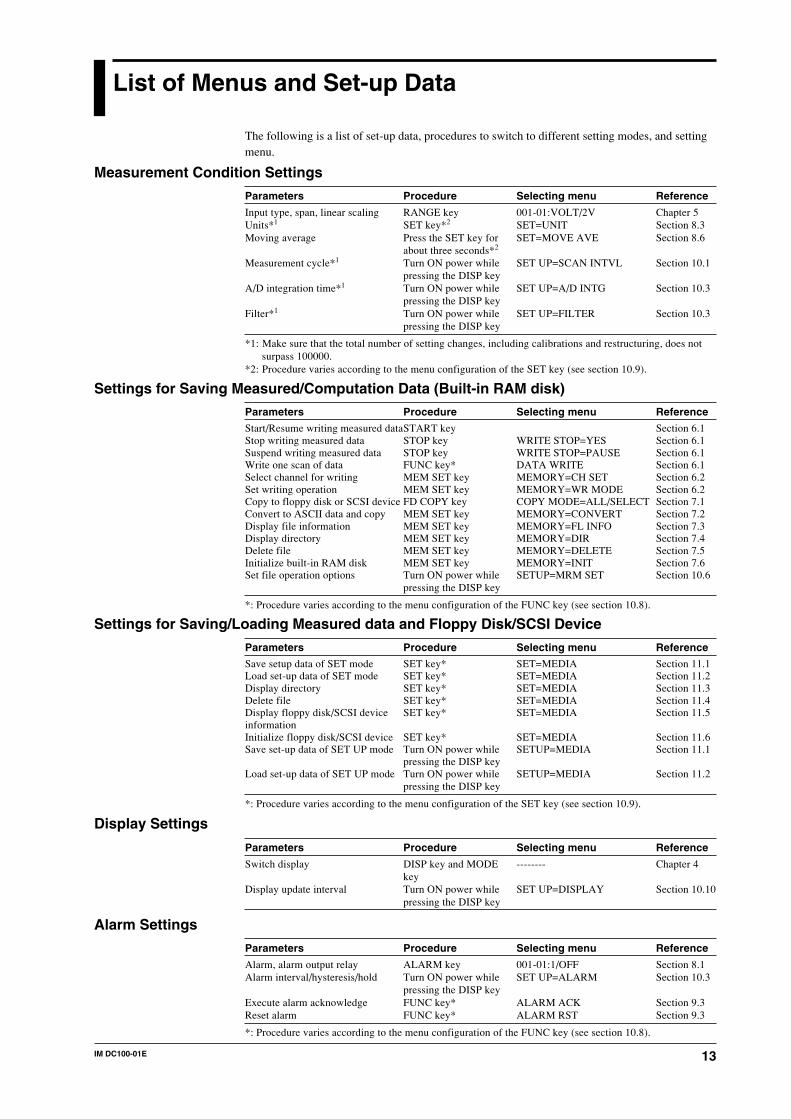
The following is a list of set-up data, procedures to switch to different setting modes, and settingmenu.
Measurement Condition Settings
Parameters Procedure Selecting menu Reference
Input type, span, linear scaling RANGE key 001-01:VOLT/2V Chapter 5Units*1 SET key*2 SET=UNIT Section 8.3Moving average Press the SET key for SET=MOVE AVE Section 8.6
about three seconds*2
Measurement cycle*1 Turn ON power while SET UP=SCAN INTVL Section 10.1pressing the DISP key
A/D integration time*1 Turn ON power while SET UP=A/D INTG Section 10.3pressing the DISP key
Filter*1 Turn ON power while SET UP=FILTER Section 10.3pressing the DISP key
*1: Make sure that the total number of setting changes, including calibrations and restructuring, does notsurpass 100000.
*2: Procedure varies according to the menu configuration of the SET key (see section 10.9).
Settings for Saving Measured/Computation Data (Built-in RAM disk)
Parameters Procedure Selecting menu Reference
Start/Resume writing measured dataSTART key Section 6.1Stop writing measured data STOP key WRITE STOP=YES Section 6.1Suspend writing measured data STOP key WRITE STOP=PAUSE Section 6.1Write one scan of data FUNC key* DATA WRITE Section 6.1Select channel for writing MEM SET key MEMORY=CH SET Section 6.2Set writing operation MEM SET key MEMORY=WR MODE Section 6.2Copy to floppy disk or SCSI device FD COPY key COPY MODE=ALL/SELECT Section 7.1Convert to ASCII data and copy MEM SET key MEMORY=CONVERT Section 7.2Display file information MEM SET key MEMORY=FL INFO Section 7.3Display directory MEM SET key MEMORY=DIR Section 7.4Delete file MEM SET key MEMORY=DELETE Section 7.5Initialize built-in RAM disk MEM SET key MEMORY=INIT Section 7.6Set file operation options Turn ON power while SETUP=MRM SET Section 10.6
pressing the DISP key
*: Procedure varies according to the menu configuration of the FUNC key (see section 10.8).
Settings for Saving/Loading Measured data and Floppy Disk/SCSI Device
Parameters Procedure Selecting menu Reference
Save setup data of SET mode SET key* SET=MEDIA Section 11.1Load set-up data of SET mode SET key* SET=MEDIA Section 11.2Display directory SET key* SET=MEDIA Section 11.3Delete file SET key* SET=MEDIA Section 11.4Display floppy disk/SCSI device SET key* SET=MEDIA Section 11.5informationInitialize floppy disk/SCSI device SET key* SET=MEDIA Section 11.6Save set-up data of SET UP mode Turn ON power while SETUP=MEDIA Section 11.1
pressing the DISP keyLoad set-up data of SET UP mode Turn ON power while SETUP=MEDIA Section 11.2
pressing the DISP key
*: Procedure varies according to the menu configuration of the SET key (see section 10.9).
Display Settings
Parameters Procedure Selecting menu Reference
Switch display DISP key and MODE -------- Chapter 4key
Display update interval Turn ON power while SET UP=DISPLAY Section 10.10pressing the DISP key
Alarm Settings
Parameters Procedure Selecting menu Reference
Alarm, alarm output relay ALARM key 001-01:1/OFF Section 8.1Alarm interval/hysteresis/hold Turn ON power while SET UP=ALARM Section 10.3
pressing the DISP keyExecute alarm acknowledge FUNC key* ALARM ACK Section 9.3Reset alarm FUNC key* ALARM RST Section 9.3
*: Procedure varies according to the menu configuration of the FUNC key (see section 10.8).
14 IM DC100-01E
List of Menus and Set-upData
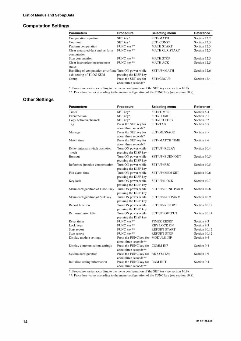
Computation Settings
Parameters Procedure Selecting menu Reference
Computation equation SET key* SET=MATH Section 12.2Constant SET key* SET=CONST Section 12.3Perform computation FUNC key** MATH START Section 12.5Clear measured data and perform FUNC key** MATH CLR START Section 12.5computationStop computation FUNC key** MATH STOP Section 12.5Clear incomplete measurement FUNC key** MATH ACK Section 12.5statusHandling of computation error/time Turn ON power while SET UP=MATH Section 12.6axis setting of TLOG SUM pressing the DISP keyGroup Press the SET key for SET=GROUP Section 12.4
about three seconds*
*: Procedure varies according to the menu configuration of the SET key (see section 10.9).**: Procedure varies according to the menu configuration of the FUNC key (see section 10.8).
Other Settings
Parameters Procedure Selecting menu Reference
Timer SET key* SET=TIMER Section 8.4Event/Action SET key* SET=LOGIC Section 9.1Copy between channels SET key* SET=CH COPY Section 9.2Tag Press the SET key for SET=TAG Section 8.5
about three seconds*Message Press the SET key for SET=MESSAGE Section 8.5
about three seconds*Match time Press the SET key for SET=MATCH TIME Section 8.6
about three seconds*Relay, internal switch operation Turn ON power while SET UP=RELAY Section 10.4 mode pressing the DISP keyBurnout Turn ON power while SET UP=BURN OUT Section 10.5
pressing the DISP keyReference junction compensation Turn ON power while SET UP=RJC Section 10.5
pressing the DISP keyFile alarm time Turn ON power while SET UP=MEM SET Section 10.6
pressing the DISP keyKey lock Turn ON power while SET UP=LOCK Section 10.7
pressing the DISP keyMenu configuration of FUNC key Turn ON power while SET UP=FUNC PARM Section 10.8
pressing the DISP keyMenu configuration of SET key Turn ON power while SET UP=SET PARM Section 10.9
pressing the DISP keyReport function Turn ON power while SET UP=REPORT Section 10.12
pressing the DISP keyRetransmission filter Turn ON power while SET UP=OUTPUT Section 10.14
pressing the DISP keyReset timer FUNC key** TIMER RESET Section 9.3Lock keys FUNC key** KEY LOCK ON Section 9.3Start report FUNC key** REPORT START Section 10.12Stop report FUNC key** REPORT STOP Section 10.12Display module settings Press the FUNC key for MODULE INF Section 9.4
about three seconds**Display communication settings Press the FUNC key for COMM INF Section 9.4
about three seconds**System configuration Press the FUNC key for RE SYSTEM Section 3.9
about three seconds**Initialize setting information Press the FUNC key for RAM INIT Section 9.4
about three seconds**
*: Procedure varies according to the menu configuration of the SET key (see section 10.9).**: Procedure varies according to the menu configuration of the FUNC key (see section 10.8).
1-1IM DC100-01E
1
System
Co
nfig
uratio
n
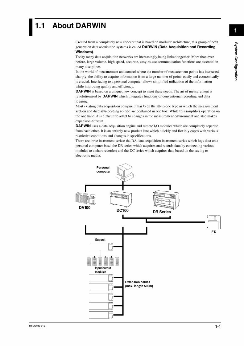
1.1 About DARWIN
Created from a completely new concept that is based on modular architecture, this group of nextgeneration data acquisition systems is called DARWIN (Data Acquisition and RecordingWindows).Today many data acquisition networks are increasingly being linked together. More than everbefore, large volume, high speed, accurate, easy-to-use communication functions are essential inmany disciplines.In the world of measurement and control where the number of measurement points has increasedsharply, the ability to acquire information from a large number of points easily and economicallyis crucial. Interfacing to a personal computer allows simplified utilization of the informationwhile improving quality and efficiency.DARWIN is based on a unique, new concept to meet these needs. The art of measurement isrevolutionized by DARWIN which integrates functions of conventional recording and datalogging.Most existing data acquisition equipment has been the all-in-one type in which the measurementsection and display/recording section are contained in one box. While this simplifies operation onthe one hand, it is difficult to adapt to changes in the measurement environment and also makesexpansion difficult.DARWIN uses a data acquisition engine and remote I/O modules which are completely separatefrom each other. It is an entirely new product line which quickly and flexibly copes with variousrestrictive conditions and changes in specifications.There are three instrument series: the DA data acquisition instrument series which logs data on apersonal computer base; the DR series which acquires and records data by connecting variousmodules to a chart recorder; and the DC series which acquires data based on the saving toelectronic media.
FD
Extension cables(max. length 500m)
Subunit
Personalcomputer
Input/outputmodules
DR SeriesDC100DA100
D
D
1-2 IM DC100-01E
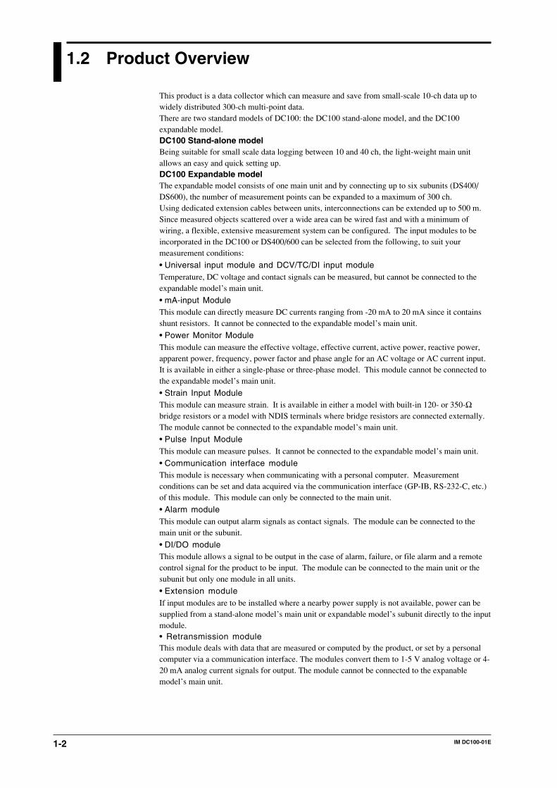
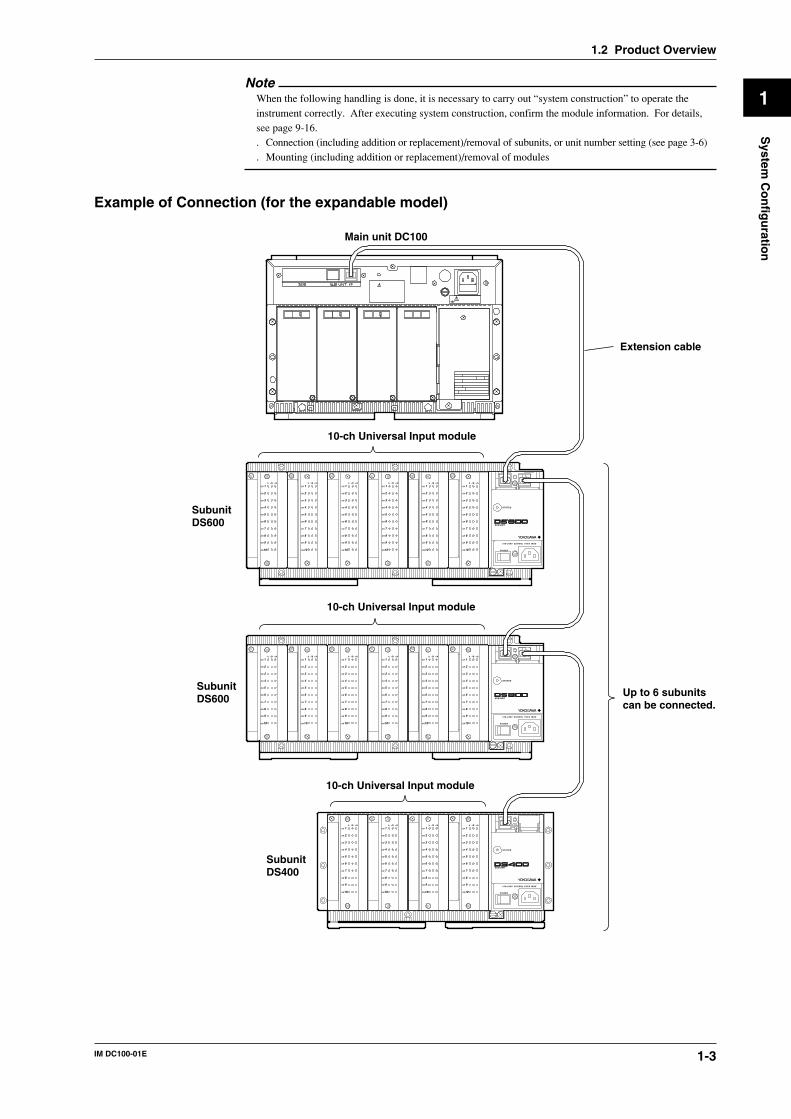
1.2 Product Overview
This product is a data collector which can measure and save from small-scale 10-ch data up towidely distributed 300-ch multi-point data.There are two standard models of DC100: the DC100 stand-alone model, and the DC100expandable model.DC100 Stand-alone modelBeing suitable for small scale data logging between 10 and 40 ch, the light-weight main unitallows an easy and quick setting up.DC100 Expandable modelThe expandable model consists of one main unit and by connecting up to six subunits (DS400/DS600), the number of measurement points can be expanded to a maximum of 300 ch.Using dedicated extension cables between units, interconnections can be extended up to 500 m.Since measured objects scattered over a wide area can be wired fast and with a minimum ofwiring, a flexible, extensive measurement system can be configured. The input modules to beincorporated in the DC100 or DS400/600 can be selected from the following, to suit yourmeasurement conditions:
• Universal input module and DCV/TC/DI input moduleTemperature, DC voltage and contact signals can be measured, but cannot be connected to theexpandable model’s main unit.
• mA-input ModuleThis module can directly measure DC currents ranging from -20 mA to 20 mA since it containsshunt resistors. It cannot be connected to the expandable model’s main unit.
• Power Monitor ModuleThis module can measure the effective voltage, effective current, active power, reactive power,apparent power, frequency, power factor and phase angle for an AC voltage or AC current input.It is available in either a single-phase or three-phase model. This module cannot be connected tothe expandable model’s main unit.
• Strain Input ModuleThis module can measure strain. It is available in either a model with built-in 120- or 350-Ωbridge resistors or a model with NDIS terminals where bridge resistors are connected externally.The module cannot be connected to the expandable model’s main unit.
• Pulse Input ModuleThis module can measure pulses. It cannot be connected to the expandable model’s main unit.
• Communication interface moduleThis module is necessary when communicating with a personal computer. Measurementconditions can be set and data acquired via the communication interface (GP-IB, RS-232-C, etc.)of this module. This module can only be connected to the main unit.
• Alarm moduleThis module can output alarm signals as contact signals. The module can be connected to themain unit or the subunit.
• DI/DO moduleThis module allows a signal to be output in the case of alarm, failure, or file alarm and a remotecontrol signal for the product to be input. The module can be connected to the main unit or thesubunit but only one module in all units.
• Extension moduleIf input modules are to be installed where a nearby power supply is not available, power can besupplied from a stand-alone model’s main unit or expandable model’s subunit directly to the inputmodule.• Retransmission moduleThis module deals with data that are measured or computed by the product, or set by a personalcomputer via a communication interface. The modules convert them to 1-5 V analog voltage or 4-20 mA analog current signals for output. The module cannot be connected to the expanablemodel’s main unit.
1-3IM DC100-01E
1
System
Co
nfig
uratio
n
NoteWhen the following handling is done, it is necessary to carry out “system construction” to operate theinstrument correctly. After executing system construction, confirm the module information. For details,see page 9-16.. Connection (including addition or replacement)/removal of subunits, or unit number setting (see page 3-6). Mounting (including addition or replacement)/removal of modules
Example of Connection (for the expandable model)
SubunitDS600
SubunitDS600
SubunitDS400
Extension cable
10-ch Universal Input module
10-ch Universal Input module
10-ch Universal Input module
Up to 6 subunitscan be connected.
Main unit DC100
CH 1
CH 2
CH 3
CH 4
CH 5
CH 6
CH 7
CH 8
CH 9
CH10
b -/B +/A
CH 1
CH 2
CH 3
CH 4
CH 5
CH 6
CH 7
CH 8
CH 9
CH10
b -/B +/A
CH 1
CH 2
CH 3
CH 4
CH 5
CH 6
CH 7
CH 8
CH 9
CH10
b -/B +/A
CH 1
CH 2
CH 3
CH 4
CH 5
CH 6
CH 7
CH 8
CH 9
CH10
b -/B +/A
CH 1
CH 2
CH 3
CH 4
CH 5
CH 6
CH 7
CH 8
CH 9
CH10
b -/B +/A
CH 1
CH 2
CH 3
CH 4
CH 5
CH 6
CH 7
CH 8
CH 9
CH10
b -/B +/A
CH 1
CH 2
CH 3
CH 4
CH 5
CH 6
CH 7
CH 8
CH 9
CH10
b -/B +/A
CH 1
CH 2
CH 3
CH 4
CH 5
CH 6
CH 7
CH 8
CH 9
CH10
b -/B +/A
CH 1
CH 2
CH 3
CH 4
CH 5
CH 6
CH 7
CH 8
CH 9
CH10
b -/B +/A
CH 1
CH 2
CH 3
CH 4
CH 5
CH 6
CH 7
CH 8
CH 9
CH10
b -/B +/A
CH 1
CH 2
CH 3
CH 4
CH 5
CH 6
CH 7
CH 8
CH 9
CH10
b -/B +/A
CH 1
CH 2
CH 3
CH 4
CH 5
CH 6
CH 7
CH 8
CH 9
CH10
b -/B +/A
CH 1
CH 2
CH 3
CH 4
CH 5
CH 6
CH 7
CH 8
CH 9
CH10
b -/B +/A
CH 1
CH 2
CH 3
CH 4
CH 5
CH 6
CH 7
CH 8
CH 9
CH10
b -/B +/A
CH 1
CH 2
CH 3
CH 4
CH 5
CH 6
CH 7
CH 8
CH 9
CH10
b -/B +/A
CH 1
CH 2
CH 3
CH 4
CH 5
CH 6
CH 7
CH 8
CH 9
CH10
b -/B +/A
SUB UNIT
POWER
STATUS
POWER
STATUS
POWER
100-240V 50/60Hz 55VA MAX
STATUS
100-240V 50/60Hz 70VA MAX
SUB UNIT
100-240V 50/60Hz 70VA MAX
SUB UNIT
1.2 Product Overview

1-4 IM DC100-01E
1.3 Names of Parts
DC100 Stand-alone Model (DC100-1)
Front
Main display (See chapter 4.)Sub-display 1 (See chapter 4.)
Sub-display 2 (See chapter 4.)
Status indicator
Operation panel(See chapters 3 to 12.)
Power switch (See page 3-26)
Floppy disk drive
POWER
DISP MODE START
STOP
FD COPY
ESC
DELINS
M,FUNCENTER
DATACOLLECTOR
FUNC CLOCK
RANGE ALARM
MEMSET SET
RECORD
ALARM
KEYLOCK
RearAC power supply model
SCSI WARNING
100-240V AC
MODEL
NO.
SUFFIX
SUPPLYFREQUENCY
Made in Japan
STYLE
50/60Hz 130VA MAXFUSE 250V/T2.5A
SUB UNIT I/F
Power fuse ( See page 13-2)
Terminals
Power connector( See page 3-27)
Function grounding terminalSCSI Connector
DC power supply model
Function grounding terminal
DC power connector( See page 3-29)
DC power fuse( See page 13-2)
Terminals
SCSI Connector
1-5IM DC100-01E
1
System
Co
nfig
uratio
n
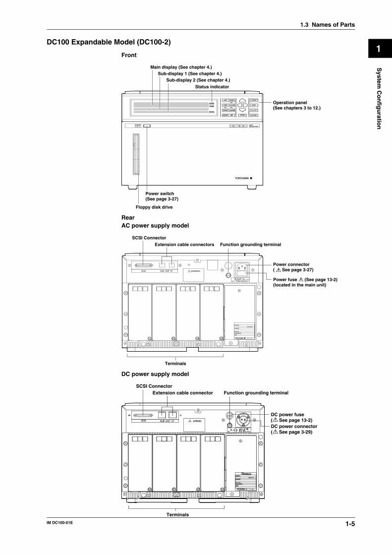
DC100 Expandable Model (DC100-2)
Front
Main display (See chapter 4.)Sub-display 1 (See chapter 4.)
Sub-display 2 (See chapter 4.)
Status indicator
Operation panel(See chapters 3 to 12.)
Power switch(See page 3-27)
Floppy disk drive
RECORD
ALARM
KEYLOCK
POWER
DISP MODE START
STOP
FD COPY
ESC
DELINS
M,FUNCENTER
DATACOLLECTOR
FUNC CLOCK
RANGE ALARM
MEMSET SET
RearAC power supply model
SCSI WARNING
100-240V AC
MODEL
NO.
SUFFIX
SUPPLYFREQUENCY
Made in Japan
STYLE
50/60Hz 130VA MAXFUSE 250V/T2.5A
SUB UNIT I/F
Function grounding terminalExtension cable connectors
SCSI Connector
Power connector( See page 3-27)
Power fuse (See page 13-2)(located in the main unit)
Terminals
DC power supply model
Function grounding terminal
Terminals
Extension cable connector
DC power connector( See page 3-29)
DC power fuse( See page 13-2)
SCSI Connector
1.3 Names of Parts
1-6 IM DC100-01E
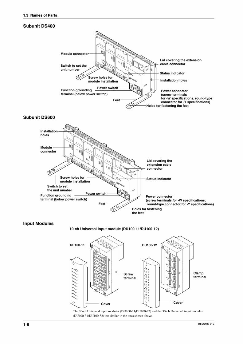
Subunit DS400
Power connector(screw terminals for -W specifications, round-type connector for -Y specifications)
Power switch
Feet
Status indicator
Module connector
Installation holesScrew holes for module installation
Holes for fastening the feet
Lid covering the extensioncable connectorSwitch to set the
unit number
Function groundingterminal (below power switch)
Subunit DS600
Power connector(screw terminals for -W specifications, round-type connector for -Y specifications)
Power switch
Feet
Status indicator
Module connector
Installationholes
Screw holes formodule installation
Holes for fasteningthe feet
Lid covering the extension cable connector
Switch to setthe unit number
Function groundingterminal (below power switch)
Input Modules10-ch Universal input module (DU100-11/DU100-12)
Cover
Screwterminal
DU100-11
Cover
Clampterminal
DU100-12
The 20-ch Universal input modules (DU100-21/DU100-22) and the 30-ch Universal input modules(DU100-31/DU100-32) are similar to the ones shown above.
1.3 Names of Parts
1-7IM DC100-01E
1
System
Co
nfig
uratio
n
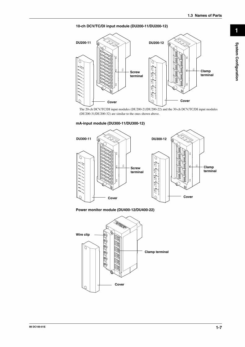
10-ch DCV/TC/DI input module (DU200-11/DU200-12)
Cover
Screwterminal
DU200-11
Cover
Clampterminal
DU200-12
The 20-ch DCV/TC/DI input modules (DU200-21/DU200-22) and the 30-ch DCV/TC/DI input modules(DU200-31/DU200-32) are similar to the ones shown above.
mA-input module (DU300-11/DU300-12)
Cover
Screwterminal
Cover
Clampterminal
DU300-11 DU300-12
Power monitor module (DU400-12/DU400-22)
Cover
Wire clip
Clamp terminal
1.3 Names of Parts

1-8 IM DC100-01E
Strain input module (DU500-12/DU500-13/DU500-14)
DU500-14DU500-12/DU500-13
NDIS terminal
Gauge method setup switch
Clamp terminalCover
Pulse input module (DU600-11)
Cover
Screw terminal
Digital input module (DU700-11)
Cover
Screwterminal
DU700-11
1.3 Names of Parts
1-9IM DC100-01E
1
System
Co
nfig
uratio
n
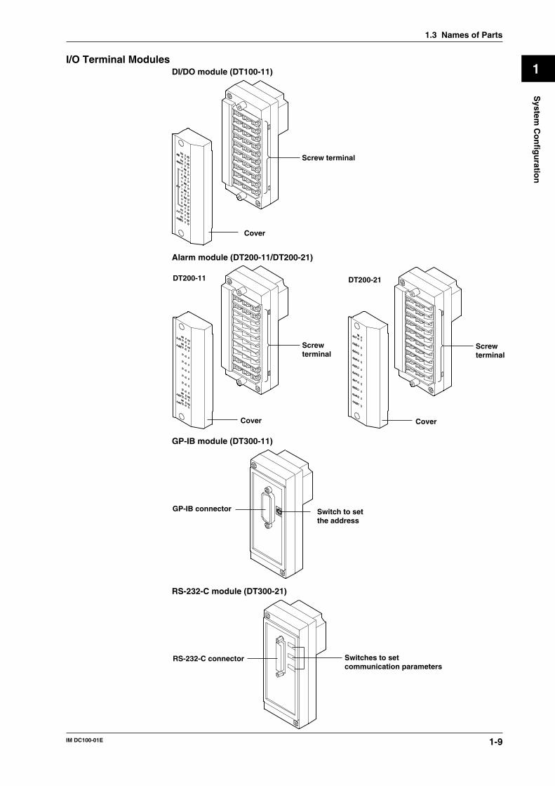
I/O Terminal ModulesDI/DO module (DT100-11)
Cover
Screw terminal
Alarm module (DT200-11/DT200-21)
Cover
Screw terminal
DT200-11
Cover
Screw terminal
DT200-21
GP-IB module (DT300-11)
GP-IB connector Switch to set the address
RS-232-C module (DT300-21)
RS-232-C connector Switches to set communication parameters
1.3 Names of Parts
1-10 IM DC100-01E
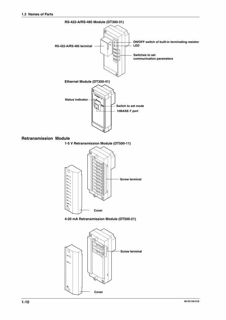
RS-422-A/RS-485 Module (DT300-31)
ON/OFF switch of built-in terminating resistorLED
Switches to setcommunication parameters
RS-422-A/RS-485 terminal
Ethernet Module (DT300-41)
Switch to set mode
Status indicator
10BASE-T port
Retransmission Module1-5 V Retransmission Module (DT500-11)
Screw terminal
Cover
4-20 mA Retransmission Module (DT500-21)
1.3 Names of Parts
Cover
Screw terminal
1-11IM DC100-01E
1
System
Co
nfig
uratio
n
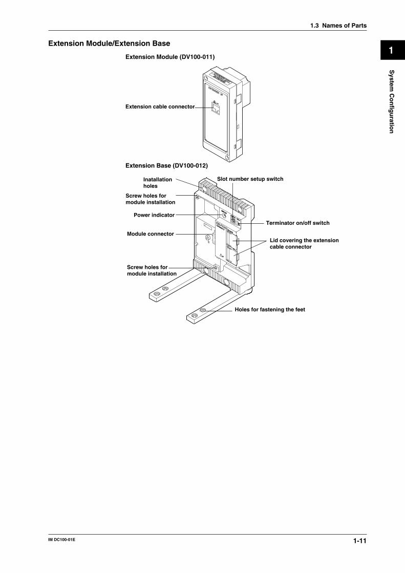
Extension Module/Extension Base
Extension Module (DV100-011)
EXTENDERI/F
I/F
Extension cable connector
Extension Base (DV100-012)
Lid covering the extensioncable connector
Holes for fastening the feet
Terminator on/off switch
Slot number setup switchInatallationholes
Screw holes formodule installation
Power indicator
Module connector
Screw holes formodule installation
1.3 Names of Parts
1-12 IM DC100-01E
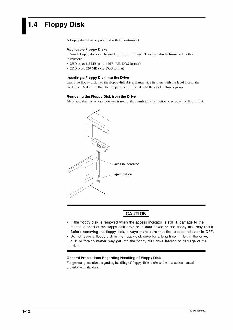
1.4 Floppy Disk
A floppy disk drive is provided with the instrument.
Applicable Floppy Disks3. 5-inch floppy disks can be used for this instrument. They can also be formatted on thisinstrument.• 2HD type: 1.2 MB or 1.44 MB (MS-DOS format)• 2DD type: 720 MB (MS-DOS format)
Inserting a Floppy Disk into the DriveInsert the floppy disk into the floppy disk drive, shutter side first and with the label face in theright side. Make sure that the floppy disk is inserted until the eject button pops up.
Removing the Floppy Disk from the DriveMake sure that the access indicator is not lit, then push the eject button to remove the floppy disk.
eject button
access indicator
CAUTION
• If the floppy disk is removed when the access indicator is still lit, damage to themagnetic head of the floppy disk drive or to data saved on the floppy disk may result.Before removing the floppy disk, always make sure that the access indicator is OFF.
• Do not leave a floppy disk in the floppy disk drive for a long time. If left in the drive,dust or foreign matter may get into the floppy disk drive leading to damage of thedrive.
General Precautions Regarding Handling of Floppy DiskFor general precautions regarding handling of floppy disks, refer to the instruction manualprovided with the disk.
2-1IM DC100-01E
2
Fu
nctio
ns
2.1 Display Functions
The inter-active front panel display consists of three rows. The first row is the main display, andthe second and third row are sub-display 1 and 2 respectively.
Monitor Mode and Status DisplayMonitor Mode• Auto Mode
This mode can be set for the main display, sub-display 1 and sub-display 2. Measurementvalues of all channels will be consecutively displayed with update interval.
• Manual ModeThis mode can be set for the main display, sub-display 1 and sub-display 2. Measurementvalues of a single channel will be displayed. The display update interval is the same as themeasurement interval (refer to page 2-4).
• Page ModeThis mode can be set for the main display. When choosing this display, the measurement valuesof 5 consecutive channels will be displayed as a page using also sub-display 1 and 2. Thedisplay update interval is the same as the measurement interval (refer to page 2-4).
• File Utilization ModeThis mode can be set in sub 1/sub 2 display. File utilization during writing is displayed on abar graph. The display update period is one second.
• Memory Utilization ModeThis mode can be set in sub 1/sub 2 display. Built-in RAM disk utilization is displayed on abar graph. The display update period is one second.
• Alarm Search ModeThis mode can be set for the main display, sub-display 1 and sub-display 2. Channels at whichan alarm occurred will be searched for and their measurement values displayed. The displayupdate interval is 2 seconds.
• Bargraph ModeThis mode can be set for sub-display 1. Measurement values which are shown on the maindisplay will be shown as a bargraph. The display update interval is the same as the interval ofthe main display.
• Alarm Status ModeThis mode can be set for sub-display 1 and 2. The display will show per channel whether or notan alarm occurred (refer to page 2-7). On one display the alarm status of a maximum of 30channels can be monitored (depending on the number of input channels). The display updateinterval is 0.5 seconds.
• Relay Status ModeThis mode can be set for sub-display 1 and 2. The display will show the operating status ofinternal switches/alarm output relays (refer to page 2-7). On one display a maximum of 30relay statuses can be monitored. The display update interval is 1 second.
• Clock ModeThis mode can only be set for sub-display 2. The current date and time are shown.
• Displaying the Selected ModeTo the right of sub-display 1 the currently selected display mode is shown for a specificdisplay.
Status DisplayIndicators at the right side of the display will light up to show that data saving is in progress (referto page 2-5), alarms are occuring (refer to page 2-7), and keys are locked (refer to page 2-11).
Remote/Local Status DisplayThe status of remote/local control will be shown on sub-display 2. Keys cannot be operated inremote control.

2-2 IM DC100-01E
Display for Setting the Type of Input, Computation and Saving ConditionsMenus for setting each of the following functions will be displayed.• measurement input functions (refer to page 2-3)• data-saving functions (refer to page 2-5)• alarm functions (refer to page 2-7)• calculation functions (refer to page 2-10)• event/action function, key-lock function and external in/output function (refer to page 2-11, 12)
Display for Setting Fundamental FunctionsMenus for performing fundamental settings will be displayed.
2.1 Display Functions
2-3IM DC100-01E
2
Fu
nctio
ns
2.2 Measurement Input Functions
Input TypeDC VoltageMeasurements can be done after selecting the measurement range per channel. The minimumrange is 20 mV, the maximum range is 50 V.
ThermocoupleMeasurements can be done after selecting the type of thermocouple per channel. The availabletypes are R, S, B, K, E, J, T, L, U, N, W and KPvsAu7Fe.Reference Junction Compensation (RJC) can be set to either use Internal RJC (INT) or ExternalRJC (EXT) per channel.For each channel, the burnout (thermocouple disconnection) function can be selected as either onor off, or overtravel of the measured result can be selected for either the positive (up) or negative(down) side.
Resistance Temperature DetectorMeasurements can be done after selecting the type of resistance temperature detector (RTD) perchannel. The available 17 types are Pt100 (1 mA), Pt100 (2 mA), JPt100 (1 mA), JPt100 (2 mA),Pt50 (2 mA), Ni100 (1 mA)SAMA, Ni100 (1 mA) DIN, Ni120 (1 mA), J263*B, Cu10GE,Cu10L&N, Cu10WEED, Cu10BAILEY, Pt100 (1 mA) high resolution, Pt100 (2 mA) highresolution, JPt100 (1 mA) high resolution and JPt100 (2 mA) high resolution.
Contact InputThe type of contact input can be selected from voltage level input or contact input, and datasaving can be set ON or OFF per channel. In case of the voltage level input a voltage level up to2.4 V results in saving OFF, whereas a voltage level of 2.4 V or more results in saving ON.
DC CurrentsDC currents ranging from -20 mA to 20 mA can be measured by means of the built-in 100-Ωshunt resistors.
AC Voltages/CurrentsThe effective voltage, effective current, active power, reactive power, apparent power, frequency,power factor and phase angle can be measured. The measuring range is common to all terminals.The input terminals of the module with this input mode, unlike those of modules with other inputmodes, are not consistent with a setup screen in terms of the channel number.
StrainThe module for this input mode supports the single-gauge, single-gauge three-wire (not yetsupported by the DU500-14 module), adjacent-side two-gauge, opposed-side two-gauge and four-gauge methods. If you have connected any new strain gauge or changed the measuring range, gothrough initial balancing before starting measurement.
PulsesThe module for this input mode can measure the number of pulses per second on a channel basisor detect the on/off states by means of any variations occurring in the instantaneous value everysecond. Once you connect the pulse input module, you can sum up values without the need forthe computing function.
Skipping Input ChannelsThis function allows skipping measurement, data saving and display of channels you are notusing. Measurement, data saving and display will not be done for the skipped channels.
Reference Junction Compensation (RJC)This function is to be used when measuring temperatures using thermocouples. The voltagegenerated by a thermocouple depends on the temperature of the spot of measurement and thereference junction temperature. Reference junction compensation is a function whichcompensates the temperature at the side of the measurement instrument to 0 degrees C.To compensate for the environmental temperature an internal circuit can be selected, orcompensation by a fixed compensation voltage value (external) can be set.
2-4 IM DC100-01E
Scan Interval• The duration of time (one scan) in which the measurement of all channels is carried out, is
called the scan interval.• This interval can be set to any value from 0.5 second to 60 seconds. The shortest is 40 ch/500
ms for the stand-alone model, or 300 ch/500 ms for the expandable model (varies with theshortest measurement period of the input module).
A/D Integration TimeThis instrument measures the input signal after putting it through an A/D converter. In order tominimize the noise imposed on the input signal, specific integration times exist.The integration time can be selected from 20 ms (50 Hz), 16.7 ms (60 Hz) and 100 ms (10 Hz).When “AUTO” is selected, the integration time will be automatically decided according to the 50/60 Hz frequency of the power supply.AUTO does not function if the instrument is a DC power supply model (Selecting “AUTO” willset the A/D integration time to 20 ms (50 Hz)). If you are using the instrument on a 60-Hz powersupply, set the A/D integration time to 16.7 ms (60Hz) or 100 ms (10 Hz).
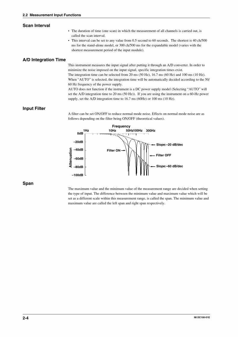
Input FilterA filter can be set ON/OFF to reduce normal mode noise. Effects on normal mode noise are asfollows depending on the filter being ON/OFF (theoretical values).
0dB
–20dB
–40dB
–60dB
–80dB
–100dB
1Hz 10Hz 100Hz50Hz 300Hz
Slope:–20 dB/dec
Slope:–60 dB/dec
Filter OFF
Filter ON
Frequency
Att
enu
atio
n
SpanThe maximum value and the minimum value of the measurement range are decided when settingthe type of input. The difference between the minimum value and maximum value which will beset as a different scale within this measurement range, is called the span. The minimum value andmaximum value are called the left span and right span respectively.
2.2 Measurement Input Functions
2-5IM DC100-01E
2
Fu
nctio
ns
2.3 Data-Saving Function
Saving Data and Saving MethodSaving MediaThe instrument can use the following media to save data:• Built-in RAM disk (standard - 1 MB; optional - 2 MB or 4 MB)• 3.5-inch floppy disk• Magneto optical disk (MO), ZIP or PD (when SCSI option /C5 is installed)Saving Object Data• Measured data/computed data• Setting data (set value in SET or SETUP mode)• Report computed data (when report function /M3 is installed)• Periodic file (when report function /M3 is installed)Saving Method• Measured data/computed data
These are saved in the built-in RAM disk. If they are to be saved on a floppy disk, MO, ZIP orPD, copy the data in the RAM disk to the floppy disk, MO, ZIP or PD. The data format isbinary (extension: .DAT). When saving on a floppy disk, MO, ZIP or PD, the data may also becopied after being converted to ASCII format (extension: .CSV).
• Setting dataThese are directly saved on a floppy disk, MO, ZIP or PD. Also, those data are read from thefloppy disk, MO, ZIP or PD to the collector itself. The data format is ASCII (extension: .PNLor .SET).
• Report DataReport data are saved to the built-in RAM disk. To save the data to the floppy disk, MO, ZIPor PD disk, copy the data from the RAM disk. Data format is binary. The file extensions are asfollows.
Hourly, daily, monthly reports : RBIThe following types of report data files are available.Hourly report: The instantaneous value at the time of the report and the average/maximum/minimum value over an hour, or the instantaneous value at the time of the report and theintegrated value/sum of the integrated values over an hour.Daily report: The instantaneous value at the time of the report and the average/maximum/minimum value over a day, or the instantaneous value at the time of the report and theintegrated value/sum of the integrated values over a day.Monthly report: The instantaneous value at the time of the report and the average/maximum/minimum value over a month, or the instantaneous value at the time of the report and theintegrated value/sum of the integrated values over a month.
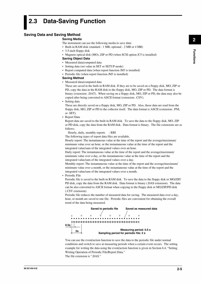
• Periodic FilePeriodic file is saved to the built-in RAM disk. To save the data to the floppy disk or MO/ZIP/PD disk, copy the data from the RAM disk. Data format is binary (.DAS extension). The datacan be also converted to ASCII format when copying to the floppy disk or MO/ZIP/PD disk(.CSV extension).Periodic file reduces the number of measured data for saving. The measured data over a day,hour, or month are saved to one file. Periodic files are convenient for obtaining the overalltrend of the data being measured.
0.5s
2s
Saved to periodic file Saved as measured data
Measuring period: 0.5 sSampling period for periodic file: 2 s
You can use the event/action function to save the data to the periodic file under normalconditions and switch to save at measuring periods when a certain event occurs. The settingexample for writing the data using the event/action function is given in Section 6.4, “SettingWriting Operation of Periodic File/Report Data.”The file extension is “.DAS.”
2-6 IM DC100-01E
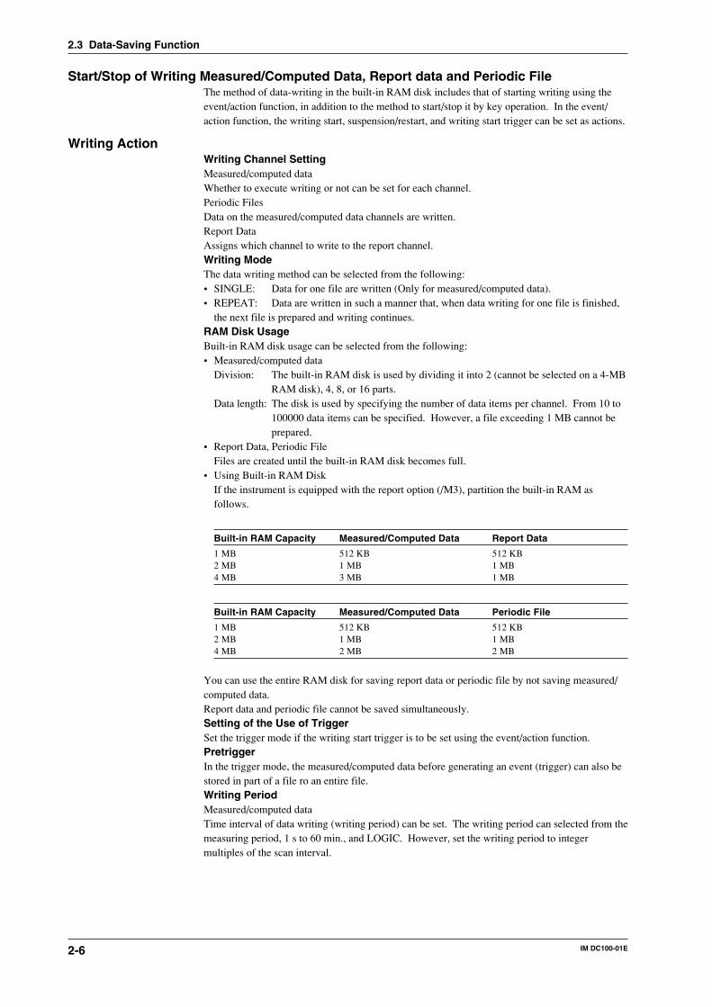
Start/Stop of Writing Measured/Computed Data, Report data and Periodic FileThe method of data-writing in the built-in RAM disk includes that of starting writing using theevent/action function, in addition to the method to start/stop it by key operation. In the event/action function, the writing start, suspension/restart, and writing start trigger can be set as actions.
Writing ActionWriting Channel SettingMeasured/computed dataWhether to execute writing or not can be set for each channel.Periodic FilesData on the measured/computed data channels are written.Report DataAssigns which channel to write to the report channel.Writing ModeThe data writing method can be selected from the following:• SINGLE: Data for one file are written (Only for measured/computed data).• REPEAT: Data are written in such a manner that, when data writing for one file is finished,
the next file is prepared and writing continues.RAM Disk UsageBuilt-in RAM disk usage can be selected from the following:• Measured/computed data
Division: The built-in RAM disk is used by dividing it into 2 (cannot be selected on a 4-MBRAM disk), 4, 8, or 16 parts.
Data length: The disk is used by specifying the number of data items per channel. From 10 to100000 data items can be specified. However, a file exceeding 1 MB cannot beprepared.
• Report Data, Periodic FileFiles are created until the built-in RAM disk becomes full.
• Using Built-in RAM DiskIf the instrument is equipped with the report option (/M3), partition the built-in RAM asfollows.
Built-in RAM Capacity Measured/Computed Data Report Data
1 MB 512 KB 512 KB2 MB 1 MB 1 MB4 MB 3 MB 1 MB
Built-in RAM Capacity Measured/Computed Data Periodic File
1 MB 512 KB 512 KB2 MB 1 MB 1 MB4 MB 2 MB 2 MB
You can use the entire RAM disk for saving report data or periodic file by not saving measured/computed data.Report data and periodic file cannot be saved simultaneously.Setting of the Use of TriggerSet the trigger mode if the writing start trigger is to be set using the event/action function.PretriggerIn the trigger mode, the measured/computed data before generating an event (trigger) can also bestored in part of a file ro an entire file.Writing PeriodMeasured/computed dataTime interval of data writing (writing period) can be set. The writing period can selected from themeasuring period, 1 s to 60 min., and LOGIC. However, set the writing period to integermultiples of the scan interval.
2.3 Data-Saving Function
2-7IM DC100-01E
2
Fu
nctio
ns
Report DataStatistics of measured/computed data are saved as report data at the specified times.Periodic FileData are written according to the specified sampling period. Set whether to save the datahourly(one o'clock, two o'clock,...), daily, or monthly. The time for saving the data daily andmonthly is the same as the time for creating report files.Selection of Writing Object DataTo write all data or to write data from all channels except SKIP only when an alarm is generatedin even one channel can be selected.
Copying Measured/Computed Data File, Report File and Periodic FileFor copying data from the built-in RAM disk to a floppy disk, MO, ZIP or PD, there are twomethods of using key operations and automatic copying using the event/action function. Inautomatic copying, only binary data apply, copying by converting data to ASCII format is notpermitted.Report data cannot be converted to ASCII and copied.
Writing Measured/Computed Data for One ScanUsing the event/action function, measured/computed data for one scan held in key operations orin generating an event can also be written.
Saving/Reading Setting DataIn SET or SETUP mode, each setting data item can be saved on a floppy disk, MO, ZIP or PD orread from a floppy disk, MO, ZIP or PD to the instrument. Setting data in Monitor mode can beread using the event/action function in addition to key operations.
Method of Specifying File NameMeasured/computed dataWhether a file name for measured/computed data is set automatically or freely specified by theuser can be selected. A file name for setting data is freely specified by the user. The fileextension is set automatically depending on the file content.Report Data, Periodic FileFile names are set automatically.
Operation in File Saving/File Alarm FunctionContinuing Operation if the Writing Mode is REPEATIn saving data by dividing the built-in RAM disk area with the writing mode set at REPEAT, ifthere is no free area, whether or not to continue writing by clearing the file with the oldest dataand time can be set (five oldest files for periodic files).Overwriting Operation If Files with the Same Name ExistIf there are files with the same name at the start of measured/computed data writing, whether thefile is overwritten or the writing operation is suspended can be set.File Cancellation When Copying is DoneWhen copying files in the built-in RAM disk to a floppy disk, whether a file in the copying sourceis cancelled or not at the same time as copying can be set.File Alarm FunctionIf the remaining capacity of the file decreases below the corresponding specified time whilewriting measured/computed data, a file alarm is output from a relay (see 2-13).
2.3 Data-Saving Function
2-8 IM DC100-01E
2.4 Alarm Function
This function will show an alarm on the display or generate an alarm output signal when themeasurement conditions of a channel exceed/fall below preset values. Up to four alarms can beset for each channel. Alarms can be set up to 4 items per channel.
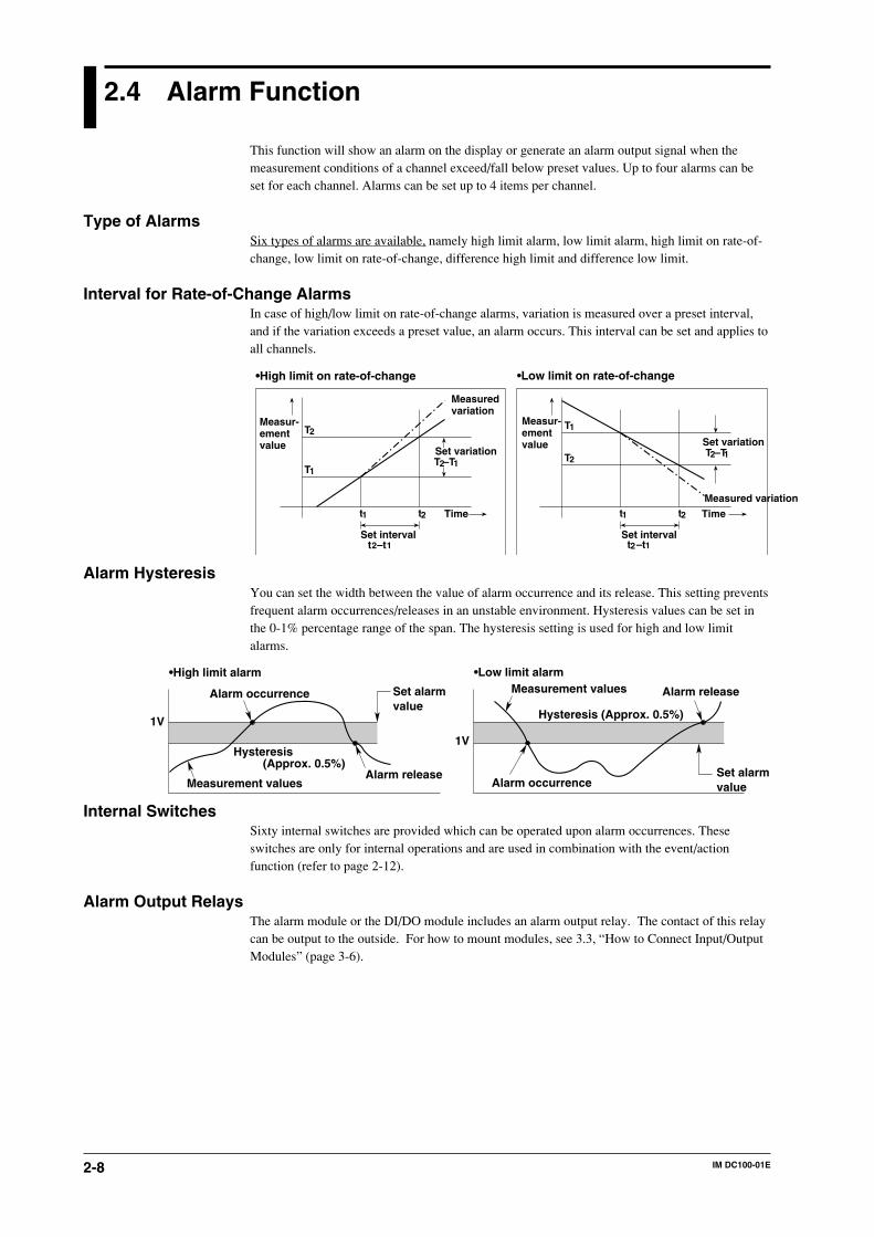
Type of AlarmsSix types of alarms are available, namely high limit alarm, low limit alarm, high limit on rate-of-change, low limit on rate-of-change, difference high limit and difference low limit.
Interval for Rate-of-Change AlarmsIn case of high/low limit on rate-of-change alarms, variation is measured over a preset interval,and if the variation exceeds a preset value, an alarm occurs. This interval can be set and applies toall channels.
Measur-ementvalue
Measuredvariation
T
Time
Set interval
1
T2
t1 t2
2 1
Set variation2 1 T
Time
2
T1
t1 t2
Measur-ementvalue
Measured variation
T –T
t –tSet interval
2 1t –t
Set variation2 1T –T
•High limit on rate-of-change •Low limit on rate-of-change
Alarm HysteresisYou can set the width between the value of alarm occurrence and its release. This setting preventsfrequent alarm occurrences/releases in an unstable environment. Hysteresis values can be set inthe 0-1% percentage range of the span. The hysteresis setting is used for high and low limitalarms.
Set alarmvalue
Alarm releaseMeasurement values
Alarm occurrence
1V
Hysteresis(Approx. 0.5%)
1V
Measurement values Alarm release
Hysteresis (Approx. 0.5%)
Set alarmvalueAlarm occurrence
•High limit alarm •Low limit alarm
Internal SwitchesSixty internal switches are provided which can be operated upon alarm occurrences. Theseswitches are only for internal operations and are used in combination with the event/actionfunction (refer to page 2-12).
Alarm Output RelaysThe alarm module or the DI/DO module includes an alarm output relay. The contact of this relaycan be output to the outside. For how to mount modules, see 3.3, “How to Connect Input/OutputModules” (page 3-6).
2-9IM DC100-01E
2
Fu
nctio
ns
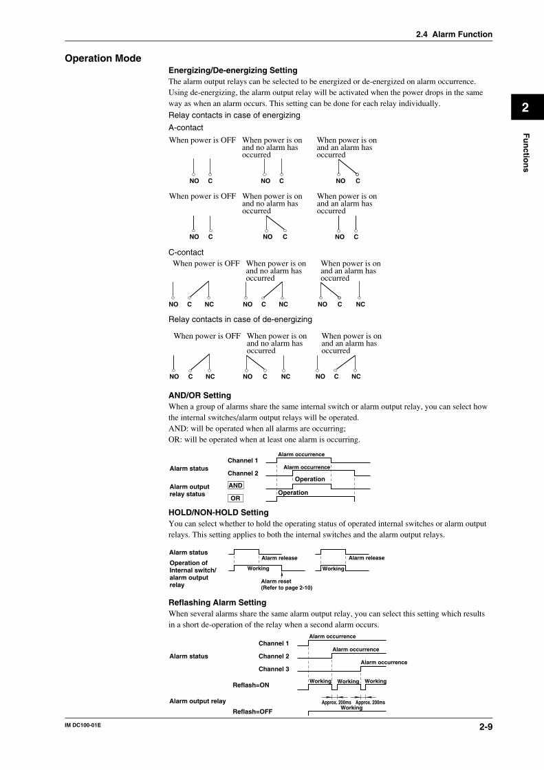
Operation ModeEnergizing/De-energizing SettingThe alarm output relays can be selected to be energized or de-energized on alarm occurrence.Using de-energizing, the alarm output relay will be activated when the power drops in the sameway as when an alarm occurs. This setting can be done for each relay individually.
Relay contacts in case of energizing
A-contact
NO C NO C
When power is OFF When power is on and no alarm hasoccurred
When power is on and an alarm hasoccurred
NO C
NO CNO C
When power is OFF When power is on and no alarm hasoccurred
When power is on and an alarm hasoccurred
NO C
C-contact
NO C NC NO C NC NO C NC
When power is OFF When power is on and no alarm hasoccurred
When power is on and an alarm hasoccurred
Relay contacts in case of de-energizing
NO C NCNO C NC NO C NC
When power is OFF When power is on and no alarm hasoccurred
When power is on and an alarm hasoccurred
AND/OR SettingWhen a group of alarms share the same internal switch or alarm output relay, you can select howthe internal switches/alarm output relays will be operated.AND: will be operated when all alarms are occurring;OR: will be operated when at least one alarm is occurring.
Alarm occurrenceChannel 1
AND
Channel 2
Alarm outputrelay status
Alarm occurrence
Operation
OperationOR
Alarm status
HOLD/NON-HOLD SettingYou can select whether to hold the operating status of operated internal switches or alarm outputrelays. This setting applies to both the internal switches and the alarm output relays.
Alarm release
Alarm reset(Refer to page 2-10)
Alarm status
Operation ofInternal switch/alarm outputrelay
Alarm release
WorkingWorking
Reflashing Alarm SettingWhen several alarms share the same alarm output relay, you can select this setting which resultsin a short de-operation of the relay when a second alarm occurs.
Reflash=ON
Reflash=OFF
Alarm status
Alarm output relay
Channel 1
Channel 2
Channel 3
Approx. 200ms Approx. 200ms
Alarm occurrence
Alarm occurrence
Alarm occurrence
WorkingWorking Working
Working
2.4 Alarm Function
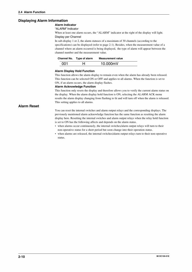
2-10 IM DC100-01E
Displaying Alarm InformationAlarm Indicator“ALARM” IndicatorWhen at least one alarm occurs, the “ALARM” indicator at the right of the display will light.
Display per ChannelIn sub-display 1 or 2, the alarm statuses of a maximum of 30 channels (according to thespecifications) can be displayed (refer to page 2-1). Besides, when the measurement value of achannel where an alarm occurred is being displayed, the type of alarm will appear between thechannel number and the measurement value.
Channel No. Type of alarm Measurement value
001 H 10.000mV
Alarm Display Hold FunctionThis function allows the alarm display to remain even when the alarm has already been released.This function can be selected ON or OFF and applies to all alarms. When the function is set toON, if an alarm occurs, the alarm display flashes.Alarm Acknowledge FunctionThis function only resets the display and therefore allows you to verify the current alarm status onthe display. When the alarm display hold function is ON, selecting the ALARM ACK menuresults the alarm display changing from flashing to lit and will turn off when the alarm is released.This setting applies to all alarms.
Alarm ResetYou can reset the internal switches and alarm output relays and the corresponding displays. Thepreviously mentioned alarm acknowledge function has the same function as resetting the alarmdisplay here. Resetting the internal switches and alarm output relays when the relay hold functionis set to ON has the following affects and depends on the alarm status.• when alarms occur continuously, the internal switches/alarm output relays will turn to their
non-operative status for a short period but soon change into their operation status.• when alarms are released, the internal switches/alarm output relays turn to their non-operative
status.
2.4 Alarm Function
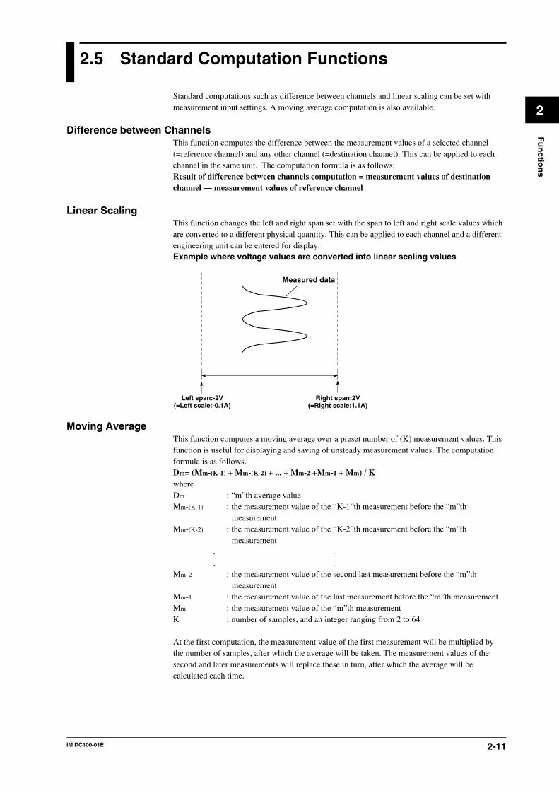
2-11IM DC100-01E
2
Fu
nctio
ns
2.5 Standard Computation Functions
Standard computations such as difference between channels and linear scaling can be set withmeasurement input settings. A moving average computation is also available.
Difference between ChannelsThis function computes the difference between the measurement values of a selected channel(=reference channel) and any other channel (=destination channel). This can be applied to eachchannel in the same unit. The computation formula is as follows:Result of difference between channels computation = measurement values of destinationchannel — measurement values of reference channel
Linear ScalingThis function changes the left and right span set with the span to left and right scale values whichare converted to a different physical quantity. This can be applied to each channel and a differentengineering unit can be entered for display.Example where voltage values are converted into linear scaling values
Left span:-2V(=Left scale:-0.1A)
Right span:2V(=Right scale:1.1A)
Measured data
Moving AverageThis function computes a moving average over a preset number of (K) measurement values. Thisfunction is useful for displaying and saving of unsteady measurement values. The computationformula is as follows.Dm= (Mm-(K-1) + Mm-(K-2) + ... + Mm-2 +Mm-1 + Mm) / KwhereDm : “m”th average valueMm-(K-1) : the measurement value of the “K-1”th measurement before the “m”th
measurementMm-(K-2) : the measurement value of the “K-2”th measurement before the “m”th
measurement. .. .
Mm-2 : the measurement value of the second last measurement before the “m”thmeasurement
Mm-1 : the measurement value of the last measurement before the “m”th measurementMm : the measurement value of the “m”th measurementK : number of samples, and an integer ranging from 2 to 64
At the first computation, the measurement value of the first measurement will be multiplied bythe number of samples, after which the average will be taken. The measurement values of thesecond and later measurements will replace these in turn, after which the average will becalculated each time.
2-12 IM DC100-01E
2.6 Other Functions
Event/Action FunctionFollowing the occurrence of an event such as remote control signal (12), alarm, internal switch,file end signal, timer, match time or key operation, any of the following actions can occur.• Alarm acknowledge
(refer to page 2-10)• Alarm reset
(refer to page 2-10)• Timer reset
This instrument can set six timers. There are two timer settings: one is the relative time settingand the other is the absolute time setting. In the relative time setting, a timer is started after thespecified numbers of days and hours have elapsed after setting. In the absolute time setting, atimer is started every specified time interval based on the reference instant. A timer resetrestores all the relative time setting timers to the state immediately after the setting before thetime elapsed.
• Message displayA preset message will be displayed on the main display
• Starting measured/computed data writingA file is opened and measured/computed data writing starts.
• Suspension/restart of measured/computed data writingWriting is suspended without closing a file. For level action, suspension and restart arealternately repeated depending on the event generation or reset.
• Writing start trigger for measured/computed data A trigger to start writing in an opened file is generated.
• Writing measured/computed data for one scanThe measured/computed data for one scan held at an event generation are written.
• Copying to a floppy disk, MO, ZIP or PDAll files in the RAM disk are copied to a floppy disk, MO, ZIP or PD.However, if a file with the same file name already exists on the SCSI device, it is not copied.
• Reading setting dataSetting data in SET mode are read into the instrument from a floppy disk, MO, ZIP or PD.
• Starting/stopping of computation, reset and clear and status clear, group resetThis function is available only if the instrument is equipped with the computation function.This function enables starting and stopping of computation and resetting and clearing ofcomputed data.
• Starting/Stopping ReportsValid only for models with the report option.Starts or stops the report function.
• FlagValid only for models with the computation option (/M1).Sets the flag to 1.
Key-Lock FunctionThis function prevents alterations by careless key operations. When the key-lock function isactivated, the indicator “KEYLOCK” at the right side of the display will be lit. All keyoperations, except power ON/OFF, DISP/MODE key and the cursor, will then be disabled.However, you can preset whether START/STOP/CLOCK/FUNC/FD COPY/M.FUNC keys willremain operable even after key-lock has been set. Furthermore, when activating or releasing thekey-lock, a menu for password verification appears to prevent the key-lock to be used byunauthorized operators.
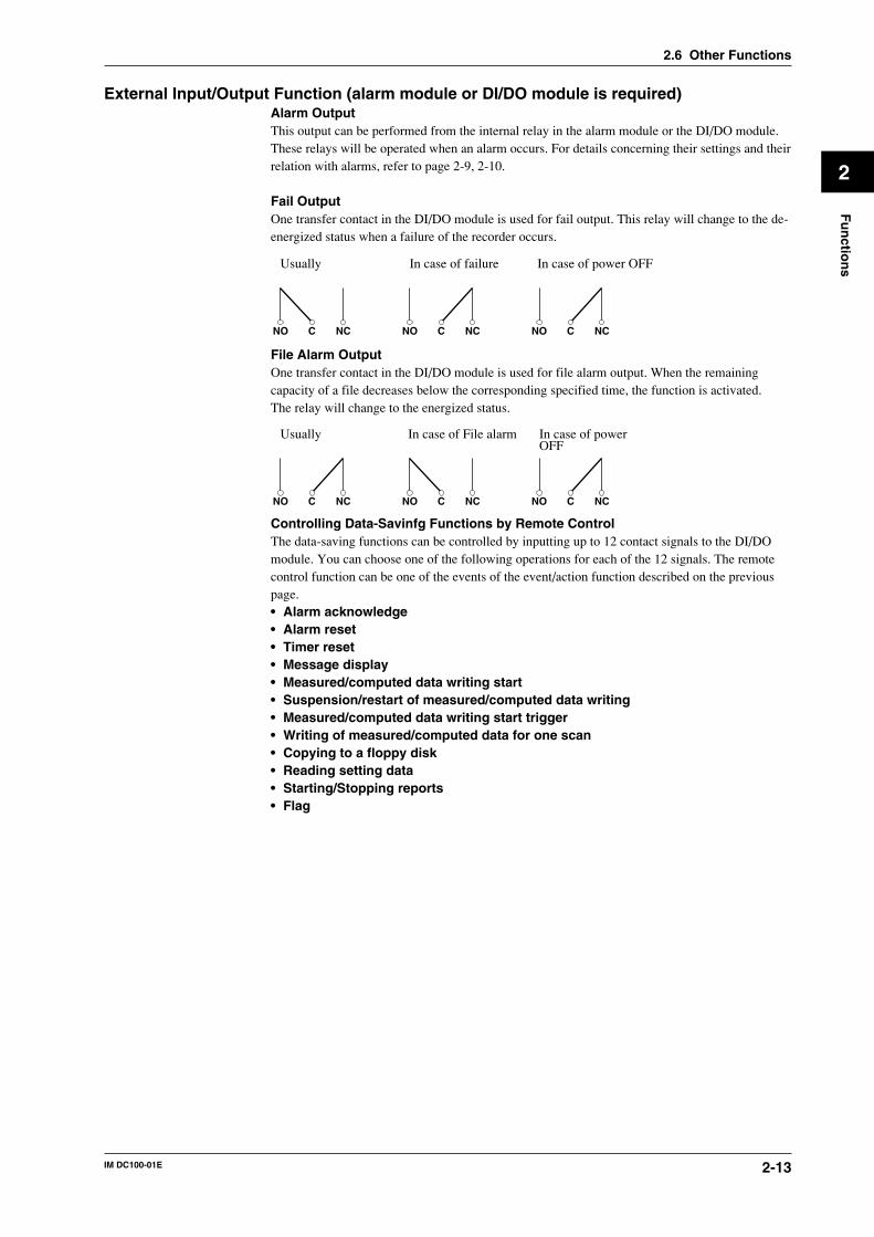
2-13IM DC100-01E
2
Fu
nctio
ns
External Input/Output Function (alarm module or DI/DO module is required)Alarm OutputThis output can be performed from the internal relay in the alarm module or the DI/DO module.These relays will be operated when an alarm occurs. For details concerning their settings and theirrelation with alarms, refer to page 2-9, 2-10.
Fail OutputOne transfer contact in the DI/DO module is used for fail output. This relay will change to the de-energized status when a failure of the recorder occurs.
NO C NC NO C NC NO C NC
Usually In case of failure In case of power OFF
File Alarm OutputOne transfer contact in the DI/DO module is used for file alarm output. When the remainingcapacity of a file decreases below the corresponding specified time, the function is activated.The relay will change to the energized status.
NO C NC NO C NC NO C NC
Usually In case of File alarm In case of powerOFF
Controlling Data-Savinfg Functions by Remote ControlThe data-saving functions can be controlled by inputting up to 12 contact signals to the DI/DOmodule. You can choose one of the following operations for each of the 12 signals. The remotecontrol function can be one of the events of the event/action function described on the previouspage.• Alarm acknowledge• Alarm reset• Timer reset• Message display• Measured/computed data writing start• Suspension/restart of measured/computed data writing• Measured/computed data writing start trigger• Writing of measured/computed data for one scan• Copying to a floppy disk• Reading setting data• Starting/Stopping reports• Flag
2.6 Other Functions
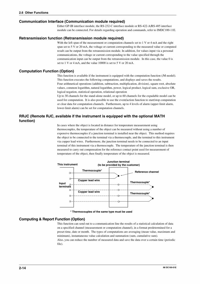
2-14 IM DC100-01E
Communication Interface (Communication module required)Either GP-IB interface module, the RS-232-C interface module or RS-422-A/RS-485 interfacemodule can be connected. For details regarding operation and commands, refer to IMDC100-11E.
Retransmission function (Retransmission module required)With the left span of the measurement or computation channels set to 1 V or 4 mA and the rightspan set to 5 V or 20 mA, the voltage or current corresponding to the measured value or computedresult can be output from the retransmission module. In addition, for values input via a personalcommunications, the voltage or current corresponding to the value specified through thecommunication input can be output from the retransmission module. In this case, the value 0 isset to 1 V or 4 mA, and the value 10000 is set to 5 V or 20 mA.
Computation Function (Option)This function is available if the instrument is equipped with the computation function (/M model).This function executes the following computations, and displays and saves the results.Four arithmetical operations (addition, subtraction, multiplication, division), square root, absolutevalues, common logarithm, natural logarithm, power, logical product, logical sum, exclusive OR,logical negation, statistical operation, relational operationUp to 30 channels for the stand-alone model, or up to 60 channels for the expadable model can beused for computation. It is also possible to use the event/action function to start/stop computationor clear data for computation channels. Furthermore, up to 4 levels of alarm (upper-limit alarm,lower-limit alarm) can be set for computation channels.
RRJC (Remote RJC, available if the instrument is equipped with the optional MATHfunction)
In cases where the object is located in distance for temperature measurement usingthermocouples, the temperature of the object can be measured without using a number ofexpensive thermocouples if a junction terminal is installed near the object. This method requiresthe object to be connected to the terminal via a thermocouple, and the terminal to this instrumentvia copper lead wires. Furthermore, the junction terminal needs to be connected to an inputterminal of this instrument via a thermocouple. The temperature of the junction terminal is thenmeasured to carry out compensation for the reference contact point used for measurement oftemperature of the object, then finally temperature of the object is measured.
This instrument
Input terminals
Thermocouple*
Copper lead wire
Copper lead wire
Thermocouple*
Thermocouple*
Junction terminal (to be provided by the customer)
Reference channel
* Thermocouples of the same type must be used
Computing & Report Function (Option)This function can send out to a communication line the results of a statistical calculation of dataon a specified channel (measurement or computation channel), in a format predetermined for apreset time, date or month. The types of computations are averaging (mean value, maximum andminimum), instantaneous value calculation and summation (sum, cumulative sum).Also, you can reduce the number of measured data and save the data over a certain time (periodicfile).
2.6 Other Functions
3-1IM DC100-01E
3
Installatio
n an
d W
iring
3.1 General Precautions for Installation
Safety PrecautionsRead the safety precautionsMake sure to read the safety precautions described on page 7 before using the instrument for thefirst time.
Do not remove any covers from the instrumentFor internal inspection or adjustment, contact your nearest sales representative. Addresses may befound on the back cover of this manual.
In case of malfunctioningNever continue to use the instrument if there are any symptoms of malfunctioning such as unusualsounds, smell or smoke coming from the instrument. Immediately turn OFF the power and unplugthe power cord. When using an adapter for direct wiring to the power supply, immediately turnOFF the power supply. Also disconnect the power to the equipment under measurement. Contactyour sales representative or nearest service center. Addresses may be found on the back cover ofthis manual.
Power CordNothing should be placed on the power cord ; it should also be kept away from any heat sources.When unplugging the power cord from the outlet, never pull the cord itself. Always hold the plugand pull it. If the power cord is damaged, contact your dealer for replacement. Refer to page 3 forthe part number when placing an order.
General Handling PrecautionsNever place anything on top of the instrumentNever place another instrument or any objects containing water on top of the instrument.Otherwise a failure may occur.
When moving the instrumentFirst turn off the power of the equipment being measured and disconnect the measurementleadwires and the communication cable. Then turn the power switch of this instrument OFF andunplug the power cord from the outlet. When carrying the instrument, securely hold theinstrument with both arms and take care not to drop it.
Ventilation openingsDo not block the ventilation openings in order not to raise the internal temperature.
Electrically charged objectsDon’t bring electrically charged objects near the input terminals. The internal circuitry might bedamaged.
ChemicalsDo not pour volatile agents on the case nor leave the case in contact with rubber or PVC productsfor a long period. The case is made of a thermoplastic resin, so take care not to let anything hotsuch as a soldering iron touch the case.
CleaningWhen cleaning the case or any other part of the instrument, first remove the power cord from thereceptacle (and in case of direct connection, disconnect the power lines). Do not use volatilechemicals since this might result in dis-coloring etc. Always use a dry, soft cloth for cleaning.
When not using the instrument for a long timeWhen the instrument is not being used for an extensive period of time, unplug the power cordfrom the outlet (when using an adapter for direct wiring to the power supply, disconnect thepower cord from the outlet).
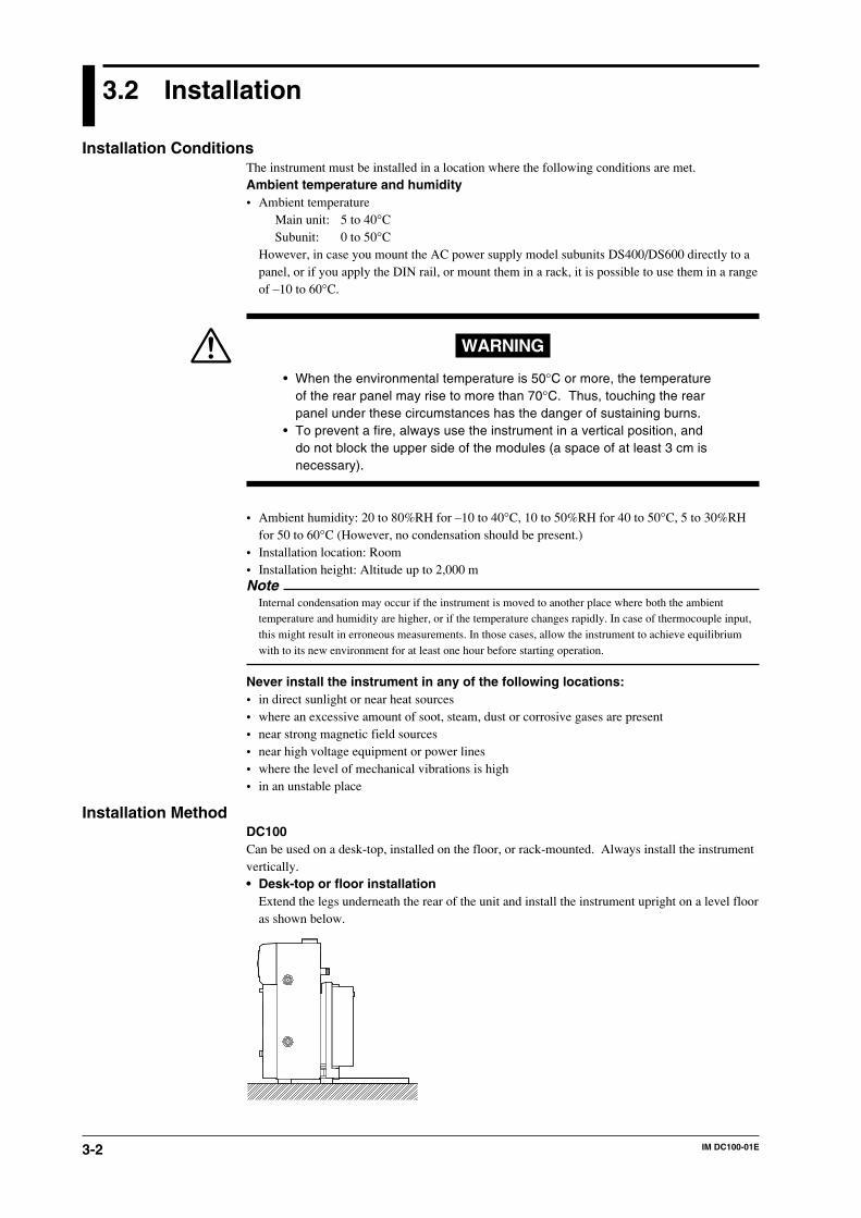
3-2 IM DC100-01E
3.2 Installation
Installation ConditionsThe instrument must be installed in a location where the following conditions are met.Ambient temperature and humidity• Ambient temperature
Main unit: 5 to 40°CSubunit: 0 to 50°C
However, in case you mount the AC power supply model subunits DS400/DS600 directly to apanel, or if you apply the DIN rail, or mount them in a rack, it is possible to use them in a rangeof –10 to 60°C.
WARNING
• When the environmental temperature is 50°C or more, the temperatureof the rear panel may rise to more than 70°C. Thus, touching the rearpanel under these circumstances has the danger of sustaining burns.
• To prevent a fire, always use the instrument in a vertical position, anddo not block the upper side of the modules (a space of at least 3 cm isnecessary).
• Ambient humidity: 20 to 80%RH for –10 to 40°C, 10 to 50%RH for 40 to 50°C, 5 to 30%RHfor 50 to 60°C (However, no condensation should be present.)
• Installation location: Room• Installation height: Altitude up to 2,000 mNote
Internal condensation may occur if the instrument is moved to another place where both the ambienttemperature and humidity are higher, or if the temperature changes rapidly. In case of thermocouple input,this might result in erroneous measurements. In those cases, allow the instrument to achieve equilibriumwith to its new environment for at least one hour before starting operation.
Never install the instrument in any of the following locations:• in direct sunlight or near heat sources• where an excessive amount of soot, steam, dust or corrosive gases are present• near strong magnetic field sources• near high voltage equipment or power lines• where the level of mechanical vibrations is high• in an unstable place
Installation MethodDC100Can be used on a desk-top, installed on the floor, or rack-mounted. Always install the instrumentvertically.• Desk-top or floor installation
Extend the legs underneath the rear of the unit and install the instrument upright on a level flooras shown below.
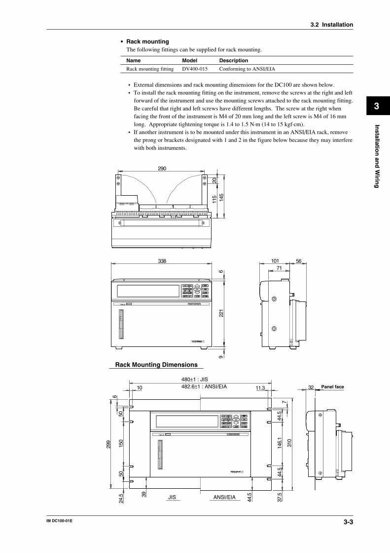
3-3IM DC100-01E
3
Installatio
n an
d W
iring
• Rack mountingThe following fittings can be supplied for rack mounting.
Name Model Description
Rack mounting fitting DV400-015 Conforming to ANSI/EIA
• External dimensions and rack mounting dimensions for the DC100 are shown below.• To install the rack mounting fitting on the instrument, remove the screws at the right and left
forward of the instrument and use the mounting screws attached to the rack mounting fitting.Be careful that right and left screws have different lengths. The screw at the right whenfacing the front of the instrument is M4 of 20 mm long and the left screw is M4 of 16 mmlong. Appropriate tightening torque is 1.4 to 1.5 N·m (14 to 15 kgf·cm).
• If another instrument is to be mounted under this instrument in an ANSI/EIA rack, removethe prong or brackets designated with 1 and 2 in the figure below because they may interferewith both instruments.
Rack Mounting Dimensions
Panel face
145
115
20
290
33871
101
480±1 : JIS
10
629
9
150
5050
39
44.5
37.5
44.5
146.
1
310
744
.5
24.5
11.3 32482.6±1 : ANSI/EIA
56
622
19
JIS ANSI/EIA
3.2 Installation
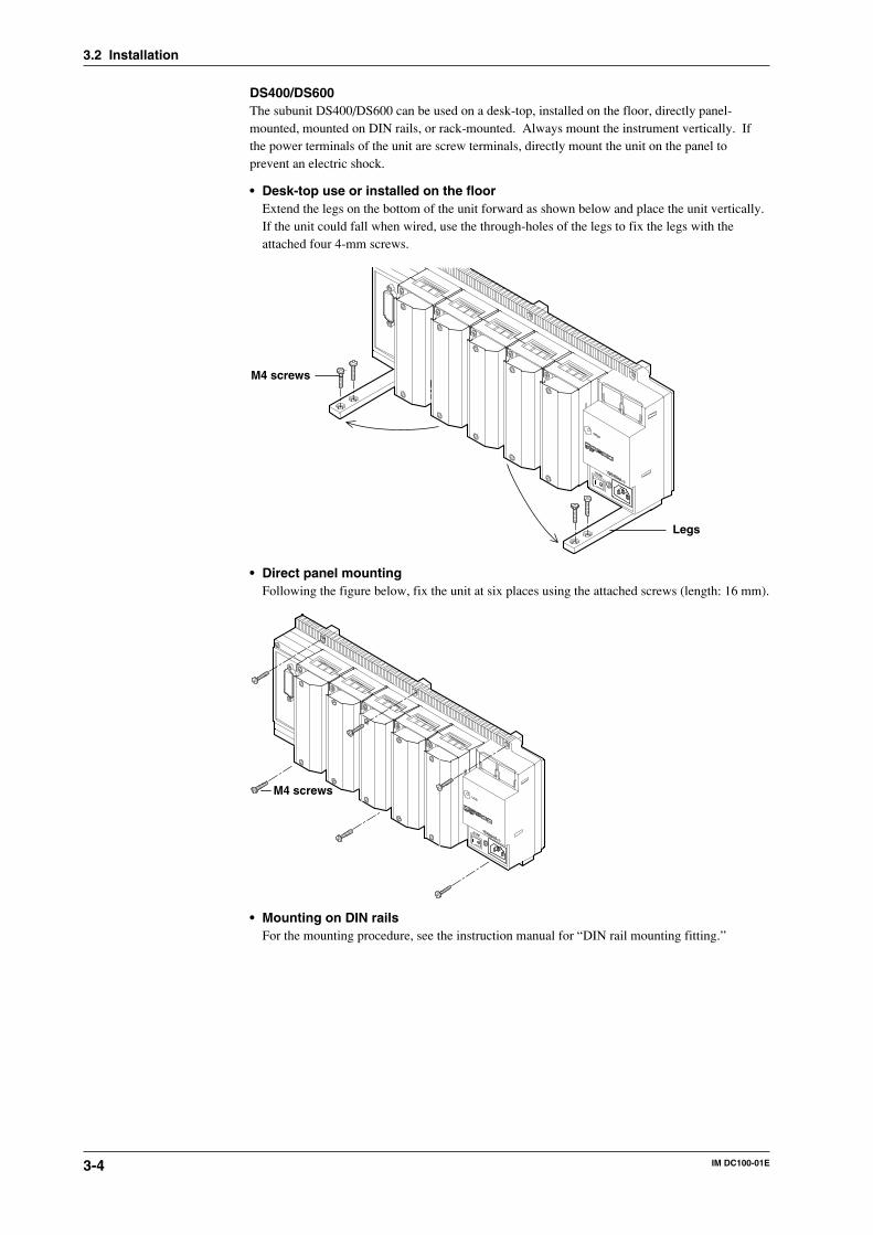
3-4 IM DC100-01E
DS400/DS600The subunit DS400/DS600 can be used on a desk-top, installed on the floor, directly panel-mounted, mounted on DIN rails, or rack-mounted. Always mount the instrument vertically. Ifthe power terminals of the unit are screw terminals, directly mount the unit on the panel toprevent an electric shock.
• Desk-top use or installed on the floorExtend the legs on the bottom of the unit forward as shown below and place the unit vertically.If the unit could fall when wired, use the through-holes of the legs to fix the legs with theattached four 4-mm screws.
Legs
M4 screws
• Direct panel mountingFollowing the figure below, fix the unit at six places using the attached screws (length: 16 mm).
M4 screws
• Mounting on DIN railsFor the mounting procedure, see the instruction manual for “DIN rail mounting fitting.”
3.2 Installation
3-5IM DC100-01E
3
Installatio
n an
d W
iring
• Rack mountingThe following fittings are supplied for rack mounting. For details of the mounting procedure,see the instruction manual for “rack mounting fitting.”
Name Model Description
Rack mounting fitting DV400-011 For DS400/DS600 conforming to ANSI/EIA
3.2 Installation
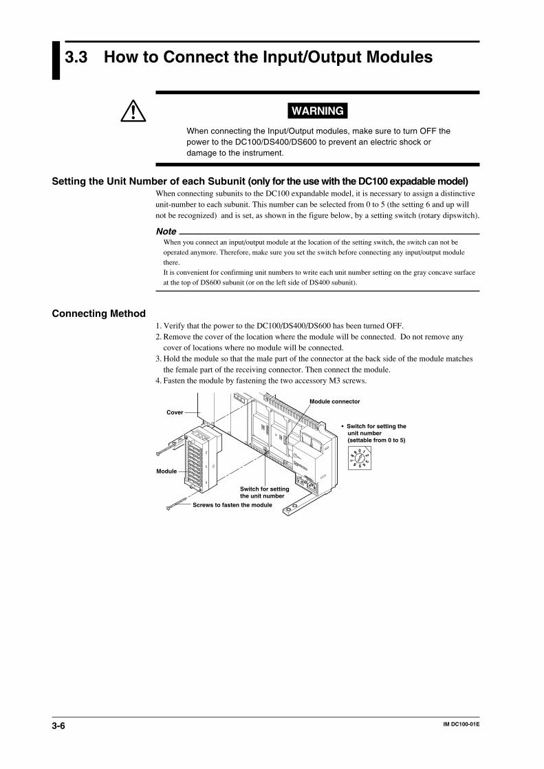
3-6 IM DC100-01E
3.3 How to Connect the Input/Output Modules
WARNING
When connecting the Input/Output modules, make sure to turn OFF thepower to the DC100/DS400/DS600 to prevent an electric shock ordamage to the instrument.
Setting the Unit Number of each Subunit (only for the use with the DC100 expadable model)When connecting subunits to the DC100 expandable model, it is necessary to assign a distinctiveunit-number to each subunit. This number can be selected from 0 to 5 (the setting 6 and up willnot be recognized) and is set, as shown in the figure below, by a setting switch (rotary dipswitch).
NoteWhen you connect an input/output module at the location of the setting switch, the switch can not beoperated anymore. Therefore, make sure you set the switch before connecting any input/output modulethere.It is convenient for confirming unit numbers to write each unit number setting on the gray concave surfaceat the top of DS600 subunit (or on the left side of DS400 subunit).
Connecting Method1. Verify that the power to the DC100/DS400/DS600 has been turned OFF.2. Remove the cover of the location where the module will be connected. Do not remove any
cover of locations where no module will be connected.3. Hold the module so that the male part of the connector at the back side of the module matches
the female part of the receiving connector. Then connect the module.4. Fasten the module by fastening the two accessory M3 screws.
0 1
23
456
78
9
Module connector
Screws to fasten the module
Module
Switch for setting the unit number
• Switch for setting the unit number (settable from 0 to 5)
Cover
3-7IM DC100-01E
3
Installatio
n an
d W
iring
Modules Which Can be Used• DC100 stand-alone model
Input module, alarm module, DI/DO module, communication interface module orretransmission moduleNumber of total modules that can be connected: 4
Number of DI/DO modules that can be connected is up to 1.Number of input modules ≤ 4 (maximum number of input channels: 40)Number of input modules + number of alarm modules + number of DI/DO modules+ number of communication interface modules + number of retransmission modules ≤ 4
• DC100 expandable modelNot more than one DI/DO module can be connected to all units.
• Main unitAlarm module, DI/DO module, or communication interface module(Note: The input module or retransmission module cannot be connected.)Number of total modules that can be connected: 4
Number of alarm modules + number of DI/DO modules + number ofcommunication interface modules ≤ 4
• Subunit (DS400/DS600)Input module, alarm module, DI/DO module, or restransmission moduleNumber of total modules that can be connected: 4 for DS400, 6 for DS600 (maximum numberof input channels: 300)
DS400: Number of input modules + number of alarm modules + number of DI/DO modules +number of retransmission module ≤ 4DS600: Number of input modules + number of alarm modules + number of DI/DO modules +number of retransmission module ≤ 6
Note• No alarm module or DI/DO module can be connected to the right side of an input module, since the rise
in temperature would hinder the measurement accuracy.• When mounting universal and power modules, or DCV/TC/DI and Power modules together, keep the two
modules apart at a distance of at least one module width. If you mount the power module immediatelybeside the universal and DCV/TC/DI module, the measuring accuracy of the universal module may fallout of its guaranteed range because of the heat radiating from the power module.
• No retransmission module can be connected to the right side of universal input module, DCV/TC/DImodule, since the rise in temperature would hinder the measurement accuracy.
• Verify the type of module by the seal on the top side.
3.3 How to Connect the Input/Output Modules
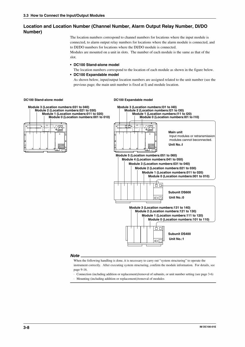
3-8 IM DC100-01E
Location and Location Number (Channel Number, Alarm Output Relay Number, DI/DONumber)
The location numbers correspond to channel numbers for locations where the input module isconnected, to alarm output relay numbers for locations where the alarm module is connected, andto DI/DO numbers for locations where the DI/DO module is connected.Modules are mounted on a unit in slots. The number of each module is the same as that of theslot.
• DC100 Stand-alone modelThe location numbers correspond to the location of each module as shown in the figure below.
• DC100 Expandable modelAs shown below, input/output location numbers are assigned related to the unit number (see theprevious page; the main unit number is fixed at I) and module location.
SCSI WARNING
100-240V AC
MODEL
NO.
SUFFIX
SUPPLYFREQUENCY
Made in Japan
STYLE
50/60Hz 130VA MAXFUSE 250V/T2.5A
SUB UNIT I/FSCSI WARNING
100-240V AC
MODEL
NO.
SUFFIX
SUPPLYFREQUENCY
Made in Japan
STYLE
50/60Hz 130VA MAXFUSE 250V/T2.5A
SUB UNIT I/F
Module 0 (Location numbers:001 to 010)Module 1 (Location numbers:011 to 020)
Module 2 (Location numbers:021 to 030)Module 3 (Location numbers:031 to 040)
Module 4 (Location numbers:041 to 050)Module 5 (Location numbers:051 to 060)
Unit No.:0
Subunit DS600
Module 0 (Location numbers:101 to 110)Module 1 (Location numbers:111 to 120)
Module 2 (Location numbers:121 to 130)Module 3 (Location numbers:131 to 140)
Unit No.:1
Subunit DS400
Unit No.:I
Main unitInput modules or retransmission modules cannot beconnected.
Module 0 (Location numbers:001 to 010)Module 1 (Location numbers:011 to 020)
Module 2 (Location numbers:021 to 030)Module 3 (Location numbers:031 to 040)
Module 0 (Location numbers:I01 to I10)Module 1 (Location numbers:I11 to I20)
Module 2 (Location numbers:I21 to I30)Module 3 (Location numbers:I31 to I40)
DC100 Stand-alone model DC100 Expandable model
NoteWhen the following handling is done, it is necessary to carry out “system structuring” to operate theinstrument correctly. After executing system structuring, confirm the module information. For details, seepage 9-16.· Connection (including addition or replacement)/removal of subunits, or unit number setting (see page 3-6)· Mounting (including addition or replacement)/removal of modules
3.3 How to Connect the Input/Output Modules
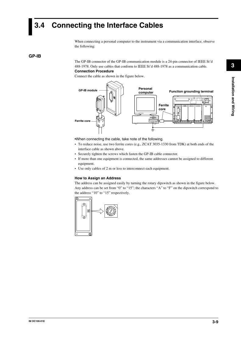
3-9IM DC100-01E
3
Installatio
n an
d W
iring
3.4 Connecting the Interface Cables
When connecting a personal computer to the instrument via a communication interface, observethe following:
GP-IBThe GP-IB connector of the GP-IB communication module is a 24-pin connector of IEEE St’d488-1978. Only use cables that conform to IEEE St’d 488-1978 as a communication cable.Connection ProcedureConnect the cable as shown in the figure below.
GP-IB module
Ferrite core
Personalcomputer
Ferritecore
Function grounding terminal
•When connecting the cable, take note of the following.• To reduce noise, use two ferrite cores (e.g., ZCAT 3035-1330 from TDK) at both ends of the
interface cable as shown above.• Securely tighten the screws which fasten the GP-IB cable connector.• If more than one equipment is connected, the same addresses cannot be assigned to different
equipment.• Use only cables of 2 m or less to interconnect each equipment.
How to Assign an AddressThe address can be assigned easily by turning the rotary dipswitch as shown in the figure below.Any address can be set from “0” to “15”; the characters “A” to “F” on the dipswitch correspond tothe address “10” to “15” respectively.
0123456789
FE
DC B A
0123456789
FE
DC B A
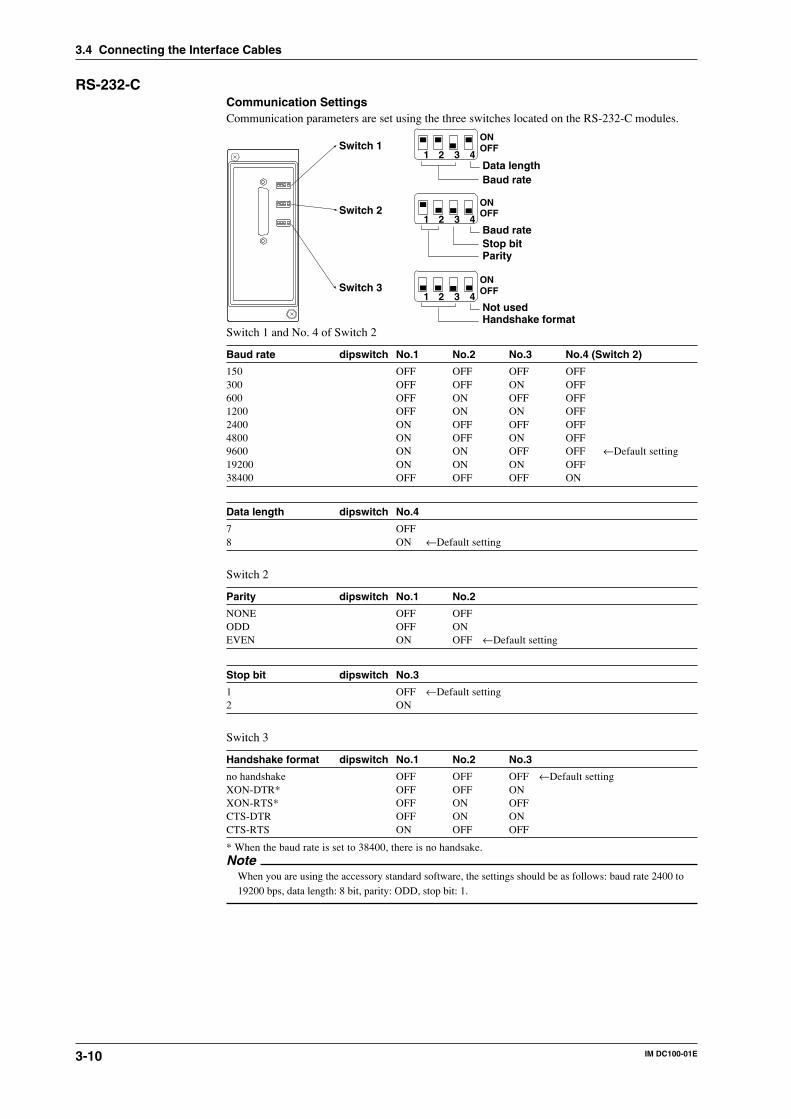
3-10 IM DC100-01E
RS-232-CCommunication SettingsCommunication parameters are set using the three switches located on the RS-232-C modules.
1 2 3 4Switch 1
Data lengthBaud rate
1 2 3 4Switch 2
Baud rate
ParityStop bit
1 2 3 4Switch 3
Not usedHandshake format
ONOFF
OFF
OFF
ON
ON
Switch 1 and No. 4 of Switch 2
Baud rate dipswitch No.1 No.2 No.3 No.4 (Switch 2)
150 OFF OFF OFF OFF300 OFF OFF ON OFF600 OFF ON OFF OFF1200 OFF ON ON OFF2400 ON OFF OFF OFF4800 ON OFF ON OFF9600 ON ON OFF OFF ←Default setting19200 ON ON ON OFF38400 OFF OFF OFF ON
Data length dipswitch No.4
7 OFF8 ON ←Default setting
Switch 2
Parity dipswitch No.1 No.2
NONE OFF OFFODD OFF ONEVEN ON OFF ←Default setting
Stop bit dipswitch No.3
1 OFF ←Default setting2 ON
Switch 3
Handshake format dipswitch No.1 No.2 No.3
no handshake OFF OFF OFF ←Default settingXON-DTR* OFF OFF ONXON-RTS* OFF ON OFFCTS-DTR OFF ON ONCTS-RTS ON OFF OFF
* When the baud rate is set to 38400, there is no handsake.Note
When you are using the accessory standard software, the settings should be as follows: baud rate 2400 to19200 bps, data length: 8 bit, parity: ODD, stop bit: 1.
3.4 Connecting the Interface Cables
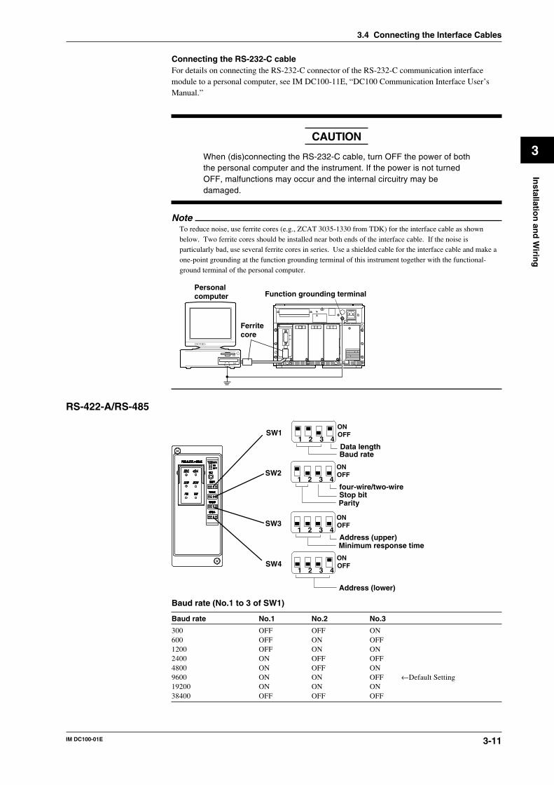
3-11IM DC100-01E
3
Installatio
n an
d W
iring
Connecting the RS-232-C cableFor details on connecting the RS-232-C connector of the RS-232-C communication interfacemodule to a personal computer, see IM DC100-11E, “DC100 Communication Interface User’sManual.”
When (dis)connecting the RS-232-C cable, turn OFF the power of boththe personal computer and the instrument. If the power is not turnedOFF, malfunctions may occur and the internal circuitry may bedamaged.
NoteTo reduce noise, use ferrite cores (e.g., ZCAT 3035-1330 from TDK) for the interface cable as shownbelow. Two ferrite cores should be installed near both ends of the interface cable. If the noise isparticularly bad, use several ferrite cores in series. Use a shielded cable for the interface cable and make aone-point grounding at the function grounding terminal of this instrument together with the functional-ground terminal of the personal computer.
Personalcomputer
Ferritecore
Function grounding terminal
RS-422-A/RS-485
1 2 3 4SW1
Data lengthBaud rate
ONOFF
1 2 3 4SW2
four-wire/two-wireStop bitParity
ONOFF
1 2 3 4SW3
Address (upper)Minimum response time
ONOFF
1 2 3 4SW4
Address (lower)
ONOFF
Baud rate (No.1 to 3 of SW1)
Baud rate No.1 No.2 No.3
300 OFF OFF ON600 OFF ON OFF1200 OFF ON ON2400 ON OFF OFF4800 ON OFF ON9600 ON ON OFF ←Default Setting19200 ON ON ON38400 OFF OFF OFF
3.4 Connecting the Interface Cables
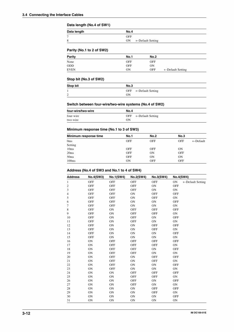
3-12 IM DC100-01E
Data length (No.4 of SW1)
Data length No.4
7 OFF8 ON ←Default Setting
Parity (No.1 to 2 of SW2)
Parity No.1 No.2
None OFF OFFODD OFF ONEVEN ON OFF ←Default Setting
Stop bit (No.3 of SW2)
Stop bit No.3
1 OFF ←Default Setting2 ON
Switch between four-wire/two-wire systems (No.4 of SW2)
four-wire/two-wire No.4
four-wire OFF ←Default Settingtwo-wire ON
Minimum response time (No.1 to 3 of SW3)
Minimum response time No.1 No.2 No.3
0ms OFF OFF OFF ←DefaultSetting10ms OFF OFF ON20ms OFF ON OFF50ms OFF ON ON100ms ON OFF OFF
Address (No.4 of SW3 and No.1 to 4 of SW4)
Address No.4(SW3) No.1(SW4) No.2(SW4) No.3(SW4) No.4(SW4)
1 OFF OFF OFF OFF ON ←Default Setting2 OFF OFF OFF ON OFF3 OFF OFF OFF ON ON4 OFF OFF ON OFF OFF5 OFF OFF ON OFF ON6 OFF OFF ON ON OFF7 OFF OFF ON ON ON8 OFF ON OFF OFF OFF9 OFF ON OFF OFF ON10 OFF ON OFF ON OFF11 OFF ON OFF ON ON12 OFF ON ON OFF OFF13 OFF ON ON OFF ON14 OFF ON ON ON OFF15 OFF ON ON ON ON16 ON OFF OFF OFF OFF17 ON OFF OFF OFF ON18 ON OFF OFF ON OFF19 ON OFF OFF ON ON20 ON OFF ON OFF OFF21 ON OFF ON OFF ON22 ON OFF ON ON OFF23 ON OFF ON ON ON24 ON ON OFF OFF OFF25 ON ON OFF OFF ON26 ON ON OFF ON OFF27 ON ON OFF ON ON28 ON ON ON OFF OFF29 ON ON ON OFF ON30 ON ON ON ON OFF31 ON ON ON ON ON
3.4 Connecting the Interface Cables
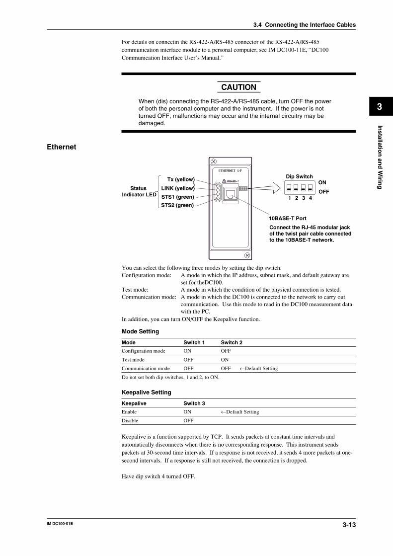
3-13IM DC100-01E
3
Installatio
n an
d W
iring
For details on connectin the RS-422-A/RS-485 connector of the RS-422-A/RS-485communication interface module to a personal computer, see IM DC100-11E, “DC100Communication Interface User’s Manual.”
CAUTION
When (dis) connecting the RS-422-A/RS-485 cable, turn OFF the powerof both the personal computer and the instrument. If the power is notturned OFF, malfunctions may occur and the internal circuitry may bedamaged.
Ethernet
Tx (yellow))
LINK (yellow)
STS1 (green)
STS2 (green)
Status Indicator LED
Dip Switch
1 2 3 4
ON
OFF
10BASE-T Port
Connect the RJ-45 modular jack of the twist pair cable connected to the 10BASE-T network.
You can select the following three modes by setting the dip switch.Configuration mode: A mode in which the IP address, subnet mask, and default gateway are
set for theDC100.Test mode: A mode in which the condition of the physical connection is tested.Communication mode: A mode in which the DC100 is connected to the network to carry out
communication. Use this mode to read in the DC100 measurement datawith the PC.
In addition, you can turn ON/OFF the Keepalive function.
Mode Setting
Mode Switch 1 Switch 2
Configuration mode ON OFF
Test mode OFF ON
Communication mode OFF OFF ←Default Setting
Do not set both dip switches, 1 and 2, to ON.
Keepalive Setting
Keepalive Switch 3
Enable ON ←Default Setting
Disable OFF
Keepalive is a function supported by TCP. It sends packets at constant time intervals andautomatically disconnects when there is no corresponding response. This instrument sendspackets at 30-second time intervals. If a response is not received, it sends 4 more packets at one-second intervals. If a response is still not received, the connection is dropped.
Have dip switch 4 turned OFF.
3.4 Connecting the Interface Cables
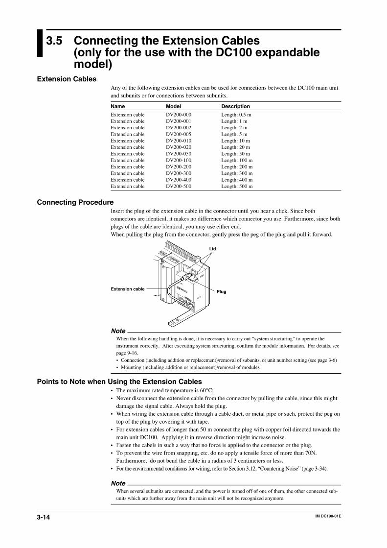
3-14 IM DC100-01E
3.5 Connecting the Extension Cables(only for the use with the DC100 expandablemodel)
Extension CablesAny of the following extension cables can be used for connections between the DC100 main unitand subunits or for connections between subunits.
Name Model Description
Extension cable DV200-000 Length: 0.5 mExtension cable DV200-001 Length: 1 mExtension cable DV200-002 Length: 2 mExtension cable DV200-005 Length: 5 mExtension cable DV200-010 Length: 10 mExtension cable DV200-020 Length: 20 mExtension cable DV200-050 Length: 50 mExtension cable DV200-100 Length: 100 mExtension cable DV200-200 Length: 200 mExtension cable DV200-300 Length: 300 mExtension cable DV200-400 Length: 400 mExtension cable DV200-500 Length: 500 m
Connecting ProcedureInsert the plug of the extension cable in the connector until you hear a click. Since bothconnectors are identical, it makes no difference which connector you use. Furthermore, since bothplugs of the cable are identical, you may use either end.When pulling the plug from the connector, gently press the peg of the plug and pull it forward.
Lid
PlugExtension cable
NoteWhen the following handling is done, it is necessary to carry out “system structuring” to operate theinstrument correctly. After executing system structuring, confirm the module information. For details, seepage 9-16.• Connection (including addition or replacement)/removal of subunits, or unit number setting (see page 3-6)• Mounting (including addition or replacement)/removal of modules
Points to Note when Using the Extension Cables• The maximum rated temperature is 60°C;• Never disconnect the extension cable from the connector by pulling the cable, since this might
damage the signal cable. Always hold the plug.• When wiring the extension cable through a cable duct, or metal pipe or such, protect the peg on
top of the plug by covering it with tape.• For extension cables of longer than 50 m connect the plug with copper foil directed towards the
main unit DC100. Applying it in reverse direction might increase noise.• Fasten the cabels in such a way that no force is applied to the connector or the plug.• To prevent the wire from snapping, etc. do no apply a tensile force of more than 70N.
Furthermore, do not bend the cable in a radius of 3 centimeters or less.• For the environmental conditions for wiring, refer to Section 3.12, “Countering Noise” (page 3-34).
NoteWhen several subunits are connected, and the power is turned off of one of them, the other connected sub-units which are further away from the main unit will not be recognized anymore.

3-15IM DC100-01E
3
Installatio
n an
d W
iring
3.6 Connecting the Signal Lines
W WARNING• To prevent electric shock, always make sure that the power supply is
turned OFF before connecting.• When 30 VAC or 60 VDC and more is applied to the output terminal of
the alarm module or the output terminal of the DI/DO module, usedouble-insulated wires (withstand voltage performance: more than 2300VAC) for those wires which apply 30 VAC or 60 VDC and more. Allother wires can be basic-insulated (withstand voltage performance:more than 1350 VAC). Furthermore, use “crimp-on” lugs (for 4-mmscrews) with insulation sleeves for connecting to the screw terminal.Make sure that the crimp-on tool must be one specified by the crimp-onlugs manufacture, and that the crimp-on lugs and tool must be matchedto the wire size.
• To avoid electrical shock, ALWAYS attach the terminal cover in placeafter the completion of wiring to the terminals so that the terminalscannot be accidentally touched.
CAUTION• Do not apply an input voltage exceeding the following levels to each
terminal of the module. Otherwise, the internal circuits may bedamaged.Universal, DCV/TC DI and digital input modules
Allowable input voltage2 VDC range or less, RTD, TC and DI (CONT): ±10 VDC6 to 20 VDC range, DI (LEVEL): ±60 VDC
Max. common mode noise voltage : 250 VAC rms (50/60 Hz)mA input module
5 VDCStrain input module
Don’t input voltage to the termialPluse input module
5 VDCDigital input of DI/DO module
–2 VDC to 7 VDC• The contact capacity of the alarm module and the digital out of DI/DO
module is as follows:250 VDC/0.1 A (with a resistor load), 250 VDC/2 A (with a resistorload), 30 VDC/2 A (with a resisitor load)
• The overvoltage category of each input module is CAT ll (IEC 1010-1).
1 Check that the power switch of this instrument is turned off.2 Remove the terminal cover. (the figure below shows DU100-11.)
Terminal cover
Screws for fastening the cover
3 Fasten the signal wires to the terminals as shown in the figure on the next page.4 Re-apply the terminal cover and fasten the screws.
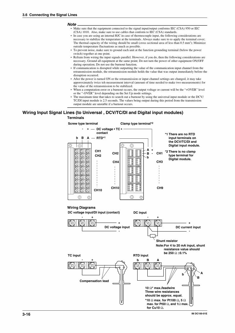
3-16 IM DC100-01E
Note• Make sure that the equipment connected to the signal input/output conforms IEC (CSA) 950 or IEC
(CSA) 1010. Also, make sure to use cables that conform to IEC (CSA) standards.• In case you are using an internal RJC in case of thermocouple input, the following considerations are
necessary to stabilize the temperature at the terminals. Always make sure to re-apply the terminal cover;The thermal capacity of the wiring should be small (cross sectional area of less than 0.5 mm2); Minimizeoutside temperature fluctuations as much as possible.
• To prevent noise, make sure to ground each unit at the function grounding terminal (below the powerswitch) together at one point.
• Refrain from wiring the input signals parallel. However, if you do, then the following considerations arenecessary. Ground all equipment at the same point; Do not turn the power of other equipment ON/OFFduring operation; Do not use the burnout function.
• If communication is disrupted while outputting the value of the communication input channel from theretransmission module, the retransmission module holds the value that was output immediately before thedisruption occurred.
• After the power is turned ON or the retransmission or input channel settings are changed, it may takeapporoximately twice teh measurement interval (amount of time needed to make two measurements) forthe value of the retransmission to be stabilized.
• When a computation error or a burnout occurs, the output voltage or current will be the “+OVER” levelor the “-OVER” level depending on the Set Up mode settings.
• The maximum time that takes to search out a burnout by using the universal input module or the DCV/TC/DI input module is 2.5 seconds. The values being output during this period from the transmissionoutput module are unstable if a burnout occurs.
Wiring Input Signal Lines (to Universal , DCV/TC/DI and Digital input modules)Terminals
Screw type terminal Clamp type terminal*2
+-
ABb
DC voltage • TC •contact
RTD*1
ABb
CH1CH2
CH10
CH1CH2
CH3CH4
CH9CH10
+-
*1 There are no RTD input terminals on the DCV/TC/DI and Digital input module.
*2 There is no clamp type terminal for Digital module.
Wiring Diagrams
DC voltage input
Compensation lead
DC current input
Shunt resistorNote:For 4 to 20 mA input, shunt resistance value should be 250 Ω ±0.1%
10 Ω* max./leadwire Three wire resistances should be approx. equal.
*10 Ω max. for Pt100 Ω, 5 Ω max. for Pt50 Ω, and 1Ω max. for Cu10 Ω.
DC input
RTD inputTC input
DC voltage input/DI input (contact)
b AB
AbB
+
-
+-+-
+
-
+-
3.6 Connecting the Signal Lines
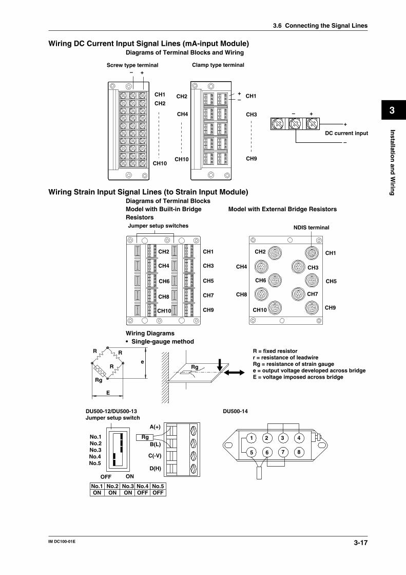
3-17IM DC100-01E
3
Installatio
n an
d W
iring
Wiring DC Current Input Signal Lines (mA-input Module)Diagrams of Terminal Blocks and Wiring
Screw type terminal Clamp type terminal+–
+–
CH1
CH2
CH10
CH1CH2
CH3CH4
CH9CH10
DC current input
+
–
+–
Wiring Strain Input Signal Lines (to Strain Input Module)Diagrams of Terminal BlocksModel with Built-in Bridge Model with External Bridge ResistorsResistors
CH2
CH3
CH5
CH7
CH9
CH1
CH4
CH6
CH8
CH10
Jumper setup switches
CH1
CH3
CH5
CH7
CH9
CH2
CH4
CH6
CH8
CH10
NDIS terminal
Wiring Diagrams• Single-gauge method
ONOFF
No.1No.2No.3No.4No.5
A(+)
B(L)
C(-V)
D(H)
DU500-12/DU500-13Jumper setup switch
DU500-14
E
e
Rg
R
R
R
Rg
No.1ON
No.2ON
No.3ON
No.4OFF
No.5OFF
Rg
R = fixed resistorr = resistance of leadwireRg = resistance of strain gaugee = output voltage developed across bridgeE = voltage imposed across bridge
1 2 3 4
5 6 7 8
3.6 Connecting the Signal Lines
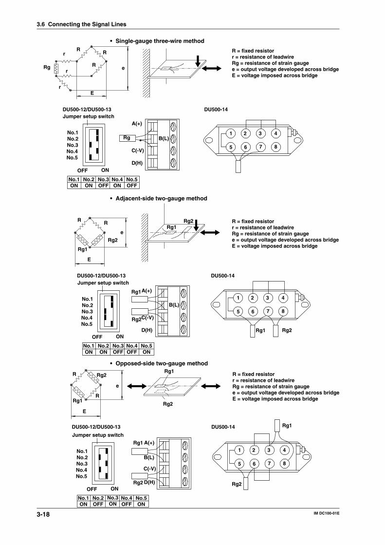
3-18 IM DC100-01E
• Single-gauge three-wire method
Jumper setup switchDU500-12/DU500-13 DU500-14
ONOFF
No.1No.2No.3No.4No.5
A(+)
B(L)
C(-V)
D(H)
No.1ON
No.2ON
No.3OFF
No.4ON
No.5OFF
R R
RRg
r
r
rE
e
R = fixed resistorr = resistance of leadwireRg = resistance of strain gaugee = output voltage developed across bridgeE = voltage imposed across bridge
Rg1 2 3 4
5 6 7 8
• Adjacent-side two-gauge method
Jumper setup switchDU500-12/DU500-13 DU500-14
ONOFF
No.1No.2No.3No.4No.5
A(+)
B(L)
C(-V)
D(H)
No.1ON
No.2ON
No.3OFF
No.4OFF
No.5ON
Rg1
Rg2
RR
E
eRg1
Rg2
Rg1
Rg2
R = fixed resistorr = resistance of leadwireRg = resistance of strain gaugee = output voltage developed across bridgeE = voltage imposed across bridge
1 2 3 4
5 6 7 8
Rg2Rg1
• Opposed-side two-gauge method
Jumper setup switch
DU500-12/DU500-13 DU500-14
ONOFF
No.1No.2No.3No.4No.5
A(+)
B(L)
C(-V)
D(H)
No.1ON
No.2OFF
No.3ON
No.4OFF
No.5ON
Rg1
Rg2
R
R
Rg2
Rg1
E
e
Rg1
Rg2
R = fixed resistorr = resistance of leadwireRg = resistance of strain gaugee = output voltage developed across bridgeE = voltage imposed across bridge
1 2 3 4
5 6 7 8
Rg2
Rg1
3.6 Connecting the Signal Lines
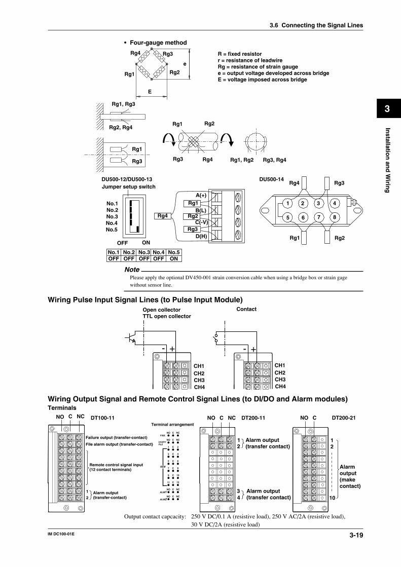
3-19IM DC100-01E
3
Installatio
n an
d W
iring
• Four-gauge method
Rg4
Rg1 Rg2
Rg3
E
e
R = fixed resistorr = resistance of leadwireRg = resistance of strain gaugee = output voltage developed across bridgeE = voltage imposed across bridge
Jumper setup switchDU500-12/DU500-13 DU500-14
ONOFF
No.1No.2No.3No.4No.5
A(+)
B(L)
C(-V)
D(H)
No.1OFF
No.2OFF
No.3OFF
No.4OFF
No.5ON
Rg1
Rg2
Rg1, Rg3
Rg2, Rg4
Rg1
Rg3
Rg1
Rg3 Rg4
Rg2
Rg1, Rg2 Rg3, Rg4
Rg3
Rg4
1 2 3 4
5 6 7 8
Rg2Rg1
Rg3Rg4
NotePlease apply the optional DV450-001 strain conversion cable when using a bridge box or strain gagewithout sensor line.
Wiring Pulse Input Signal Lines (to Pulse Input Module)
- + - +
Open collectorTTL open collector
Contact
CH1CH2CH3CH4
CH1CH2CH3CH4
Wiring Output Signal and Remote Control Signal Lines (to DI/DO and Alarm modules)Terminals
NO C NC
Failure output (transfer-contact)
REM
CHART/FILE
FAIL
ALM1
ALM2
NO
NO
1
3
5
7
9
11
NO
NO
C
C
C
C
C
C
C
C
C
C
NC
NC
2
4
6
8
10
12
NC
NC
File alarm output (transfer-contact)
Remote control signal input(12 contact terminals)
Terminal arrangement
1
2Alarm output(transfer-contact)
NO C
12
4
NC
3
Alarm output(transfer contact)
Alarm output(transfer contact)
DT200-11DT100-11 NO C
12
10
Alarmoutput(makecontact)
DT200-21
Output contact capcacity: 250 V DC/0.1 A (resistive load), 250 V AC/2A (resistive load),30 V DC/2A (resistive load)
3.6 Connecting the Signal Lines
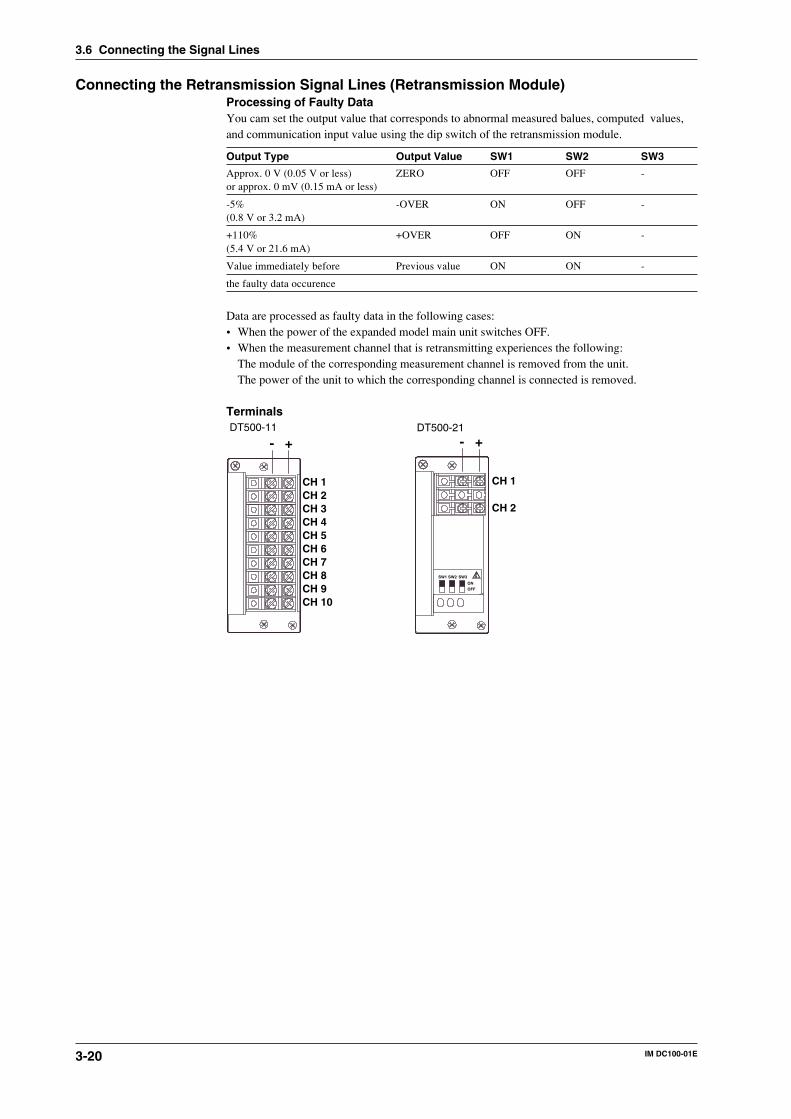
3-20 IM DC100-01E
3.6 Connecting the Signal Lines
Connecting the Retransmission Signal Lines (Retransmission Module)Processing of Faulty DataYou cam set the output value that corresponds to abnormal measured balues, computed values,and communication input value using the dip switch of the retransmission module.
Output Type Output Value SW1 SW2 SW3
Approx. 0 V (0.05 V or less) ZERO OFF OFF -or approx. 0 mV (0.15 mA or less)
-5% -OVER ON OFF -(0.8 V or 3.2 mA)
+110% +OVER OFF ON -(5.4 V or 21.6 mA)
Value immediately before Previous value ON ON -
the faulty data occurence
Data are processed as faulty data in the following cases:• When the power of the expanded model main unit switches OFF.• When the measurement channel that is retransmitting experiences the following:
The module of the corresponding measurement channel is removed from the unit.The power of the unit to which the corresponding channel is connected is removed.
Terminals
CH 1
- +
CH 2CH 3CH 4CH 5CH 6CH 7CH 8CH 9CH 10
- +
CH 1
SW1 SW3
ONOFF
SW2
CH 2
DT500-11 DT500-21
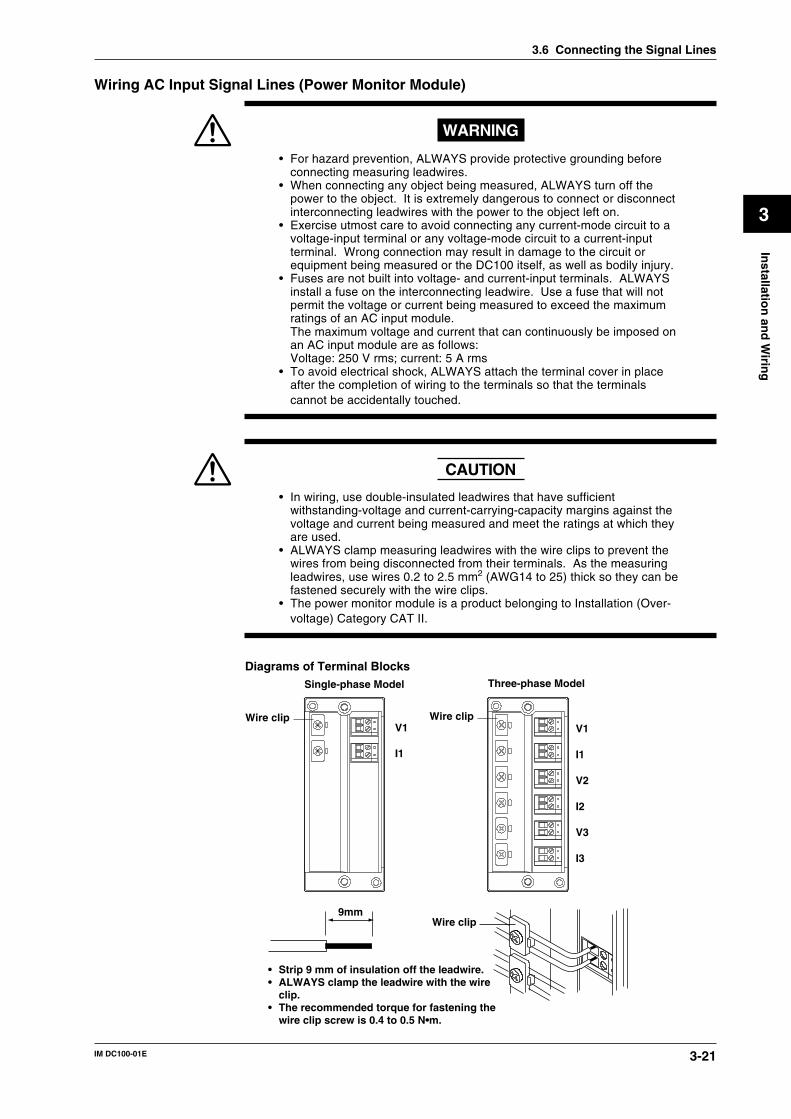
3-21IM DC100-01E
3
Installatio
n an
d W
iring
Wiring AC Input Signal Lines (Power Monitor Module)
WARNING
• For hazard prevention, ALWAYS provide protective grounding beforeconnecting measuring leadwires.
• When connecting any object being measured, ALWAYS turn off thepower to the object. It is extremely dangerous to connect or disconnectinterconnecting leadwires with the power to the object left on.
• Exercise utmost care to avoid connecting any current-mode circuit to avoltage-input terminal or any voltage-mode circuit to a current-inputterminal. Wrong connection may result in damage to the circuit orequipment being measured or the DC100 itself, as well as bodily injury.
• Fuses are not built into voltage- and current-input terminals. ALWAYSinstall a fuse on the interconnecting leadwire. Use a fuse that will notpermit the voltage or current being measured to exceed the maximumratings of an AC input module.The maximum voltage and current that can continuously be imposed onan AC input module are as follows:Voltage: 250 V rms; current: 5 A rms
• To avoid electrical shock, ALWAYS attach the terminal cover in placeafter the completion of wiring to the terminals so that the terminalscannot be accidentally touched.
CAUTION
• In wiring, use double-insulated leadwires that have sufficientwithstanding-voltage and current-carrying-capacity margins against thevoltage and current being measured and meet the ratings at which theyare used.
• ALWAYS clamp measuring leadwires with the wire clips to prevent thewires from being disconnected from their terminals. As the measuringleadwires, use wires 0.2 to 2.5 mm2 (AWG14 to 25) thick so they can befastened securely with the wire clips.
• The power monitor module is a product belonging to Installation (Over-voltage) Category CAT II.
Diagrams of Terminal Blocks
V1
I1
V1
I1
V2
I2
V3
I3
Wire clip
Single-phase Model Three-phase Model
Wire clip
Wire clip9mm
• Strip 9 mm of insulation off the leadwire.• ALWAYS clamp the leadwire with the wire
clip.• The recommended torque for fastening the
wire clip screw is 0.4 to 0.5 N•m.
3.6 Connecting the Signal Lines
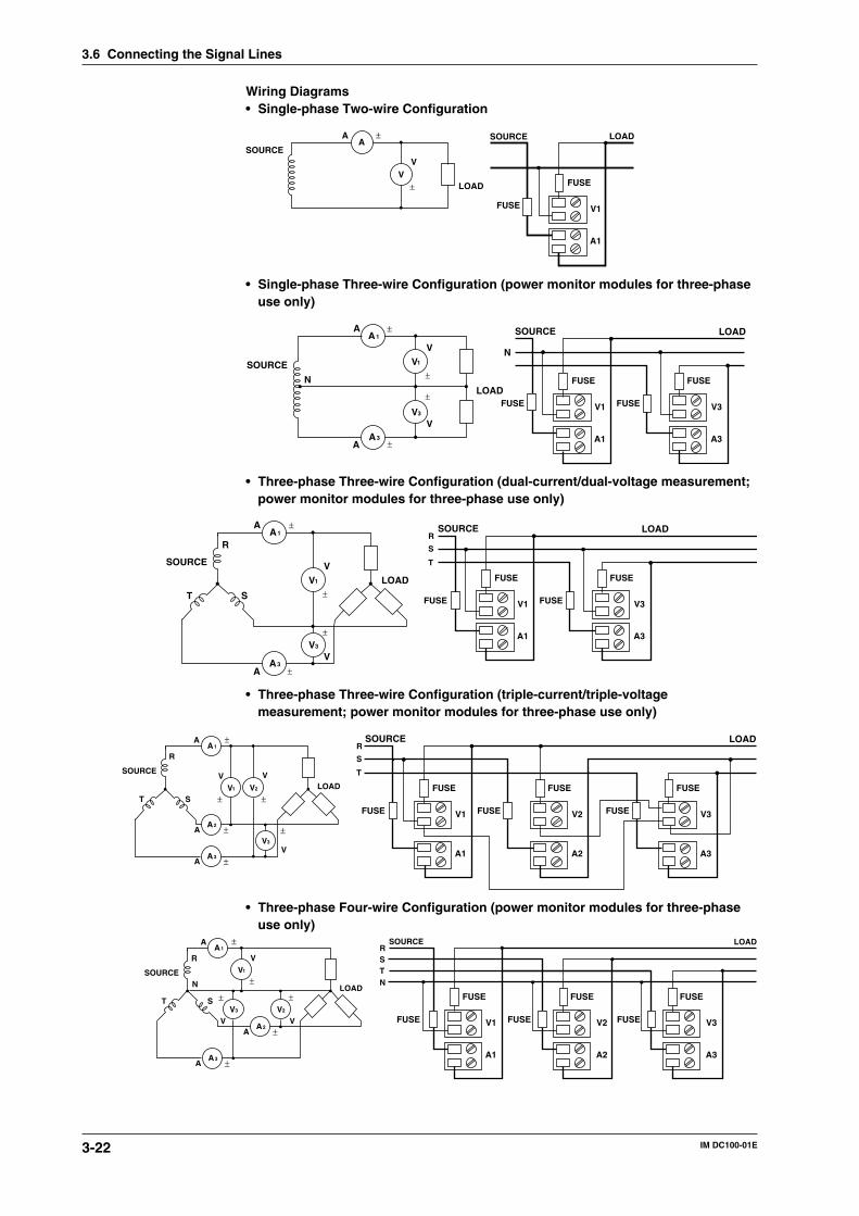
3-22 IM DC100-01E
Wiring Diagrams• Single-phase Two-wire Configuration
LOADV
±
V
A±A
SOURCE
SOURCE LOAD
FUSE
FUSE
A1
V1
• Single-phase Three-wire Configuration (power monitor modules for three-phaseuse only)
SOURCE
LOAD
V
A
±
±A
V
V
±
VA
±A
1
3
1
3
N
SOURCE LOAD
N
FUSE FUSE
FUSE
A1
V1
A3
V3FUSE
• Three-phase Three-wire Configuration (dual-current/dual-voltage measurement;power monitor modules for three-phase use only)
SOURCE
LOAD
A±A
±
AA
1
3
V±
V
VV
3
1
R
ST
±
SOURCE LOAD
S
T
R
FUSE FUSE
FUSE
A1
V1
A3
V3FUSE
• Three-phase Three-wire Configuration (triple-current/triple-voltagemeasurement; power monitor modules for three-phase use only)
SOURCE
LOAD
A±A
A±A
1
3
R
STV
±
V1
±V
V3
±V
V
2
A±A
2
SOURCE LOAD
S
T
R
FUSE FUSE
FUSE
A1
V1
A2
V2FUSE
FUSE
A3
V3FUSE
• Three-phase Four-wire Configuration (power monitor modules for three-phaseuse only)
SOURCE
LOAD
A±A
A±A
1
3
R
ST
V±
V1
±V
V3
±V
V2
A±A
2
N
LOADSOURCE
SR
TN
A1
V1
A2
V2
A3
V3FUSEFUSEFUSE
FUSEFUSEFUSE
3.6 Connecting the Signal Lines

3-23IM DC100-01E
3
Installatio
n an
d W
iring
3.7 Connecting an Extension Module to ExtensionBases
Using an extension module and extension bases, you can install input modules at a locationdistant from the subunit (s). The module and bases are powered from the subunit and, therefore,can be located even in a place where there is no power source nearby.
Installing an Extension Base
WARNING
• For fire prevention, use extension bases in an upright position.Do not cover up the extension base's module (allow a clearance of atleast 3 cm around the module).
• To prevent electric shock, connect an extension base after checkingthat the power switch of the subunit is turned off.
Ambient Temperature and HumidityUse an extension base under the following environmental conditions:
• Ambient temperature: –10˚ to 60˚C• Ambient humidity: 20 to 80% RH at -10˚ to 40˚C
10 to 50% RH at 40˚ to 50˚C5 to 30% RH at 50˚ to 60˚CUse the extension base in a condensation-free condition.
NoteCondensation may occur if you move the extension base from an area of low humidity to an area of highhumidity or if any drastic temperature variation takes place. In addition, a measurement error will result ifthe instrument is in the thermocouple input mode. In that case, allow at least one hour for the extensionbase to adjust to the ambient atmosphere before using it.
Do not install the extension base where:• it is exposed to direct sunlight or there is a heat source nearby;• soot, steam, dust and/or corrosive gas is relatively abundant;• there is a strong electromagnetic source nearby;• there is high-voltage equipment or a power line nearby;• it is exposed to severe and/or frequent mechanical vibration; or• it is not positioned stably.
Desk-top or Floor InstallationAttach the two supplied shoe plates onto the extension base with two screws (4-mm screws 16mm long, supplied as standard accessories), as shown in the figure on the left below. Then, placethe extension base in an upright position. If the base is liable to fall on its side after wiring, fixthe shoe plates with the four supplied screws (4-mm screws 12 mm long) using the through-holes(for 4-mm screws) of the shoe plates.
Direct Mounting on PanelAccording to the figure on the right below, fix the extension base onto a panel by fastening thefour corners with the supplied screws (4-mm screws 12 mm long).
M4 × 16 mm
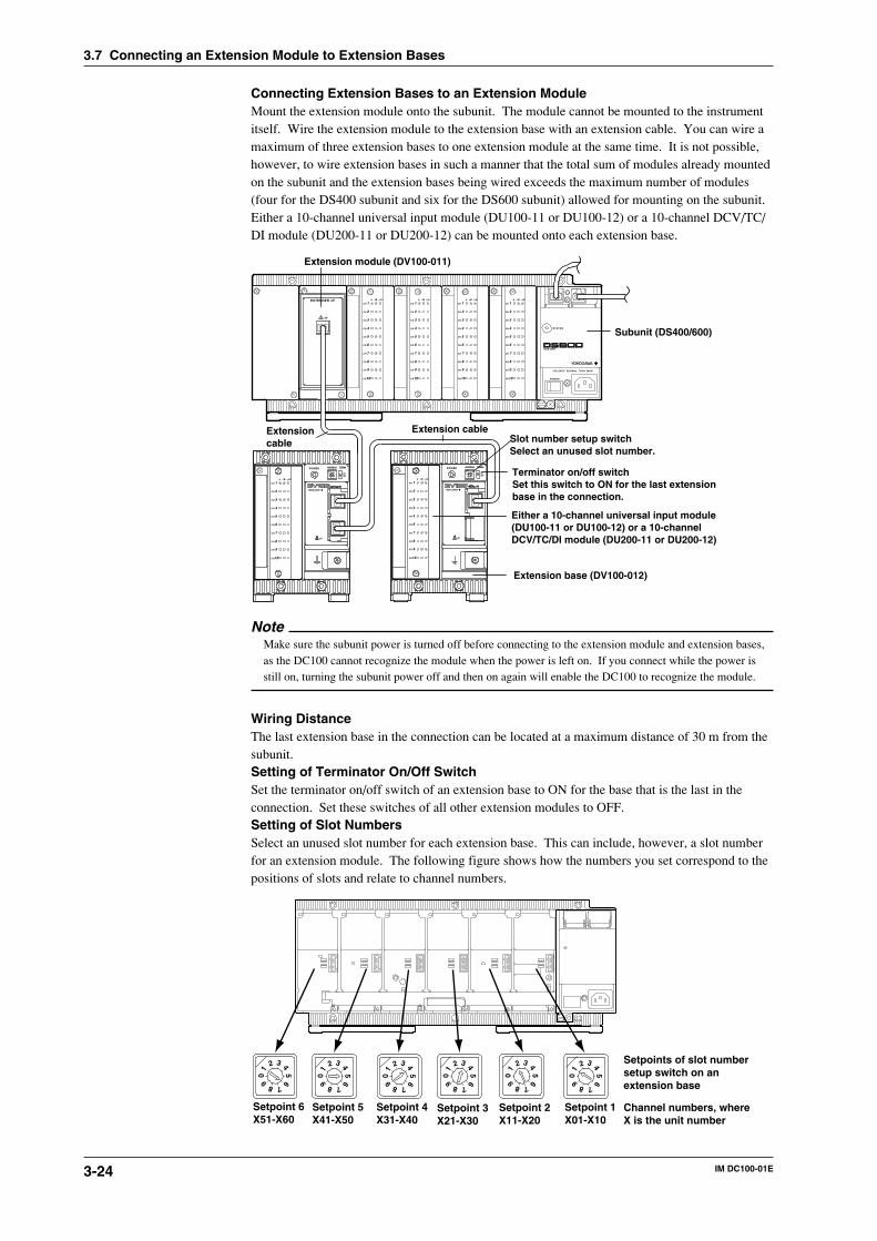
3-24 IM DC100-01E
Connecting Extension Bases to an Extension ModuleMount the extension module onto the subunit. The module cannot be mounted to the instrumentitself. Wire the extension module to the extension base with an extension cable. You can wire amaximum of three extension bases to one extension module at the same time. It is not possible,however, to wire extension bases in such a manner that the total sum of modules already mountedon the subunit and the extension bases being wired exceeds the maximum number of modules(four for the DS400 subunit and six for the DS600 subunit) allowed for mounting on the subunit.Either a 10-channel universal input module (DU100-11 or DU100-12) or a 10-channel DCV/TC/DI module (DU200-11 or DU200-12) can be mounted onto each extension base.
CH 1
CH 2
CH 3
CH 4
CH 5
CH 6
CH 7
CH 8
CH 9
CH10
b -/B +/A
CH 1
CH 2
CH 3
CH 4
CH 5
CH 6
CH 7
CH 8
CH 9
CH10
b -/B +/A
CH 1
CH 2
CH 3
CH 4
CH 5
CH 6
CH 7
CH 8
CH 9
CH10
b -/B +/A
CH 1
CH 2
CH 3
CH 4
CH 5
CH 6
CH 7
CH 8
CH 9
CH10
b -/B +/A
POWER
STATUS
100-240V 50/60Hz 70VA MAX
SUB UNIT
EXTENDER I/F
I/F
POWER ADDRESS TERMN
ONOFF
I/F
1
2 3 45
6
7890
CH 1
CH 2
CH 3
CH 4
CH 5
CH 6
CH 7
CH 8
CH 9
CH10
b -/B +/A
POWER ADDRESS TERMN
ONOFF
I/F
1
2 3 45
6
7890
CH 1
CH 2
CH 3
CH 4
CH 5
CH 6
CH 7
CH 8
CH 9
CH10
b -/B +/A
Extension module (DV100-011)
Subunit (DS400/600)
Extensioncable
Extension cable
Extension base (DV100-012)
Terminator on/off switchSet this switch to ON for the last extensionbase in the connection.
Slot number setup switchSelect an unused slot number.
Either a 10-channel universal input module (DU100-11 or DU100-12) or a 10-channel DCV/TC/DI module (DU200-11 or DU200-12)
NoteMake sure the subunit power is turned off before connecting to the extension module and extension bases,as the DC100 cannot recognize the module when the power is left on. If you connect while the power isstill on, turning the subunit power off and then on again will enable the DC100 to recognize the module.
Wiring DistanceThe last extension base in the connection can be located at a maximum distance of 30 m from thesubunit.Setting of Terminator On/Off SwitchSet the terminator on/off switch of an extension base to ON for the base that is the last in theconnection. Set these switches of all other extension modules to OFF.Setting of Slot NumbersSelect an unused slot number for each extension base. This can include, however, a slot numberfor an extension module. The following figure shows how the numbers you set correspond to thepositions of slots and relate to channel numbers.
1
2 3 45
6
7890
1
2 3 45
6
7890
1
2 3 45
6
7890
1
2 3 45
6
7890
1
2 3 45
6
7890
1
2 3 45
6
7890
Setpoint 1X01-X10
Setpoint 2X11-X20
Setpoint 3X21-X30
Setpoint 4X31-X40
Setpoint 5X41-X50
Setpoint 6X51-X60
Setpoints of slot number setup switch on an extension base
Channel numbers, where X is the unit number
3.7 Connecting an Extension Module to Extension Bases
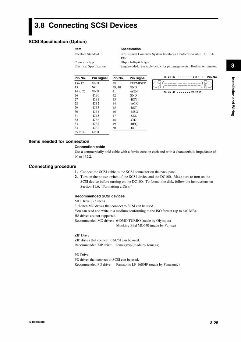
3-25IM DC100-01E
3
Installatio
n an
d W
iring
3.8 Connecting SCSI Devices
SCSI Specification (Option)
Item Specification
Interface Standard SCSI (Small Computer System Interface), Conforms to ANSI X3.131-1986
Connector type 50-pin half-pitch typeElectrical Specification Single-ended. See table below for pin assignments. Built-in terminator.
Pin No. Pin Signal
1 to 12 GND13 NC14 to 25 GND26 -DB027 -DB128 -DB229 -DB330 -DB431 -DB532 -DB633 -DB734 -DBP35 to 37 GND
Items needed for connectionConnection cableUse a commercially-sold cable with a ferrite core on each end with a characteristic impedance of90 to 132Ω.
Connecting procedure1. Connect the SCSI cable to the SCSI connector on the back panel.2. Turn on the power switch of the SCSI device and the DC100. Make sure to turn on the
SCSI device before turning on the DC100. To format the disk, follow the instructions onSection 11.6, “Formatting a Disk.”
Recommended SCSI devicesMO Drive (3.5 inch)3. 5-inch MO drives that connect to SCSI can be used.You can read and write to a medium conforming to the ISO format (up to 640 MB).HS drives are not supported.Recommended MO drives: 640MO TURBO (made by Olympus)
Mocking Bird MO640 (made by Fujitsu)
ZIP DriveZIP drives that connect to SCSI can be used.Recommended ZIP drive: Iomegazip (made by Iomega)
PD DrivePD drives that connect to SCSI can be used.Recommended PD drive: Panasonic LF-1600JP (made by Panasonic)
Pin No. Pin Signal
38 TERMPWR39, 40 GND41 -ATN42 GND43 -BSY44 -ACK45 -RST46 -MSG47 -SEL48 -C/D49 -REQ50 -I/O
125
2650
2
27
3
28
24
49
23
48
Pin No.
3-26 IM DC100-01E
Using the devices
CAUTION
Never remove the disk while the SCSI device is being accessed. It maydamage the SCSI device or destroy the data on the disk.
• Use OS, device driver, and interface card that support semi-IBM format.Contact the provider or manufacture to find out whether your OS, device driver, and interfacecard support the semi-IBM format.
• Do not connect a personal computer to the SCSI chain as it may cause the DC100 to operateimproperly.
Note• When connecting multiple SCSI devices in a chain, attach a terminator to the device at the end of the
chain. Keep the total length of the SCSI chain to 6 m or less.
• SCSI devices that are turned off will not be detected.
To detect the device, turn it on and then perform manual detection according to Section 11.7, “DetectingMO/ZIP/PD Disk Drive.”
• Connect the SCSI cable securely. Otherwise, the operation becomes unstable, and can cause operationerrors (error message numbers 120, 121, 131, 135). If these errors occur, turn OFF the SCSI device andconnect the SCSI cable securely. Then, check that the SCSI device information is displayed by followingthe steps described in section 11.5 “Displaying Floppy Disk Information.” Also, do a disk check on thepersonal computer, because sometimes the disk becomes corrupt.
• Make sure to set or attach a terminator to the furthest SCSI device from the DC100. Otherwise, theoperation becomes unstable, and can cause operation errors (error message numbers 120, 121, 131, 135).If these errors occur, turn OFF the SCSI device and set or attach the terminator. Then, check that theSCSI device information is displayed by following the steps described in section 11.5 “DisplayingFloppy Disk Information.” Also, do a disk check on the personal computer, because sometimes the diskbecomes corrupt.
• Do not turn OFF the SCSI device, remove the disk, or disconnect the SCSI cable while the SCSI deviceis being accessed. If you accidentally do so, turn OFF the SCSI device and check that the SCSI deviceinformation is displayed by following the steps described in section 11.5 “Displaying Floppy DiskInformation.” Also, do a disk check on the personal computer, because sometimes the disk becomescorrupt.
• If there are more than 1000 files on the SCSI device, copying files takes time. In addition, copying offiles sometimes fail if you are copying with the event/action function.
• Because the SCSI device is a data storing device for the computer, noise countermeasure may not beadequate. Be careful of the environment in using the SCSI device. If noise is a problem, take thefollowing measures to reduce the noise.
Attach a clamp filter (ZCAT3035-1330 by TDK) to the SCSI cable.Insert a filter or an insulation transformer at the power supply of the SCSI device.
For details, see section 3.12 “Countering Noise.”
3.8 Connecting SCSI Devices
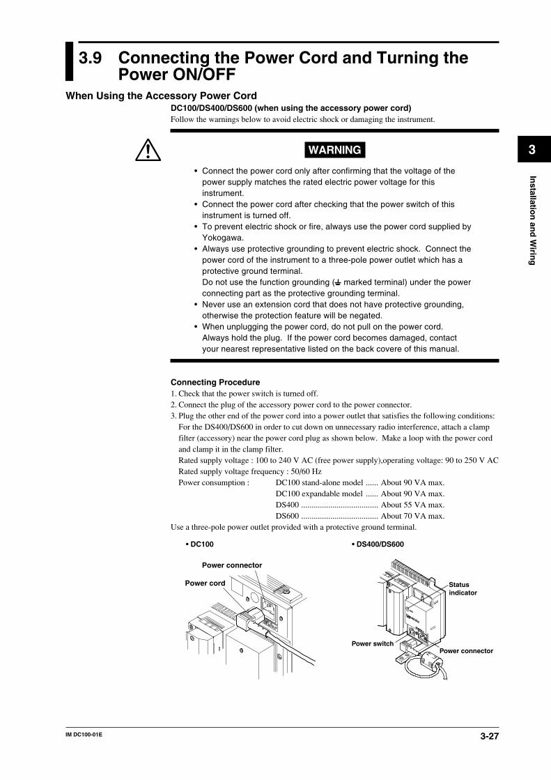
3-27IM DC100-01E
3
Installatio
n an
d W
iring
3.9 Connecting the Power Cord and Turning thePower ON/OFF
When Using the Accessory Power CordDC100/DS400/DS600 (when using the accessory power cord)Follow the warnings below to avoid electric shock or damaging the instrument.
WARNING
• Connect the power cord only after confirming that the voltage of thepower supply matches the rated electric power voltage for thisinstrument.
• Connect the power cord after checking that the power switch of thisinstrument is turned off.
• To prevent electric shock or fire, always use the power cord supplied byYokogawa.
• Always use protective grounding to prevent electric shock. Connect thepower cord of the instrument to a three-pole power outlet which has aprotective ground terminal.Do not use the function grounding ( marked terminal) under the powerconnecting part as the protective grounding terminal.
• Never use an extension cord that does not have protective grounding,otherwise the protection feature will be negated.
• When unplugging the power cord, do not pull on the power cord.Always hold the plug. If the power cord becomes damaged, contactyour nearest representative listed on the back covere of this manual.
Connecting Procedure1. Check that the power switch is turned off.2. Connect the plug of the accessory power cord to the power connector.3. Plug the other end of the power cord into a power outlet that satisfies the following conditions:
For the DS400/DS600 in order to cut down on unnecessary radio interference, attach a clampfilter (accessory) near the power cord plug as shown below. Make a loop with the power cordand clamp it in the clamp filter.Rated supply voltage : 100 to 240 V AC (free power supply),operating voltage: 90 to 250 V ACRated supply voltage frequency : 50/60 HzPower consumption : DC100 stand-alone model ...... About 90 VA max.
DC100 expandable model ...... About 90 VA max.DS400 ..................................... About 55 VA max.DS600 ..................................... About 70 VA max.
Use a three-pole power outlet provided with a protective ground terminal.
Power connector
Power cord
• DC100 • DS400/DS600
Statusindicator
Power connectorPower switch
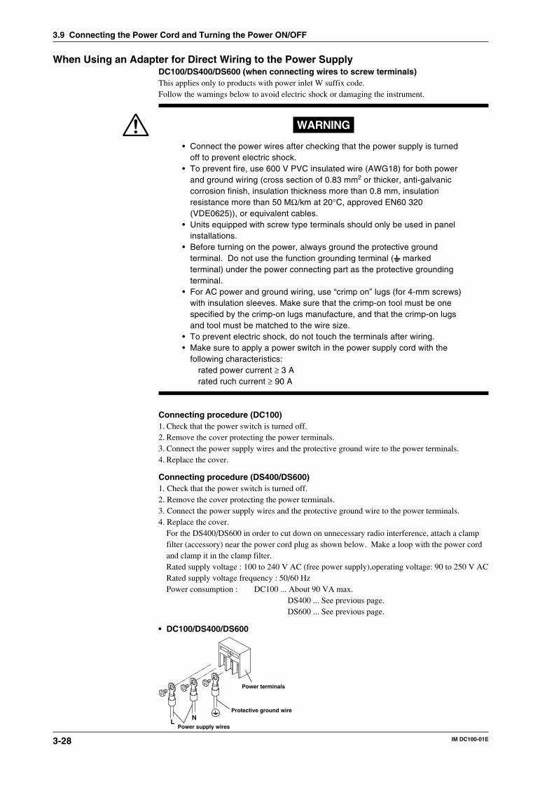
3-28 IM DC100-01E
When Using an Adapter for Direct Wiring to the Power SupplyDC100/DS400/DS600 (when connecting wires to screw terminals)This applies only to products with power inlet W suffix code.Follow the warnings below to avoid electric shock or damaging the instrument.
WARNING
• Connect the power wires after checking that the power supply is turnedoff to prevent electric shock.
• To prevent fire, use 600 V PVC insulated wire (AWG18) for both powerand ground wiring (cross section of 0.83 mm2 or thicker, anti-galvaniccorrosion finish, insulation thickness more than 0.8 mm, insulationresistance more than 50 MΩ/km at 20°C, approved EN60 320(VDE0625)), or equivalent cables.
• Units equipped with screw type terminals should only be used in panelinstallations.
• Before turning on the power, always ground the protective groundterminal. Do not use the function grounding terminal ( markedterminal) under the power connecting part as the protective groundingterminal.
• For AC power and ground wiring, use “crimp on” lugs (for 4-mm screws)with insulation sleeves. Make sure that the crimp-on tool must be onespecified by the crimp-on lugs manufacture, and that the crimp-on lugsand tool must be matched to the wire size.
• To prevent electric shock, do not touch the terminals after wiring.• Make sure to apply a power switch in the power supply cord with the
following characteristics:rated power current ≥ 3 Arated ruch current ≥ 90 A
Connecting procedure (DC100)1. Check that the power switch is turned off.2. Remove the cover protecting the power terminals.3. Connect the power supply wires and the protective ground wire to the power terminals.4. Replace the cover.
Connecting procedure (DS400/DS600)1. Check that the power switch is turned off.2. Remove the cover protecting the power terminals.3. Connect the power supply wires and the protective ground wire to the power terminals.4. Replace the cover.
For the DS400/DS600 in order to cut down on unnecessary radio interference, attach a clampfilter (accessory) near the power cord plug as shown below. Make a loop with the power cordand clamp it in the clamp filter.Rated supply voltage : 100 to 240 V AC (free power supply),operating voltage: 90 to 250 V ACRated supply voltage frequency : 50/60 HzPower consumption : DC100 ... About 90 VA max.
DS400 ... See previous page.DS600 ... See previous page.
• DC100/DS400/DS600
LN
Protective ground wire
Power supply wires
Power terminals
3.9 Connecting the Power Cord and Turning the Power ON/OFF
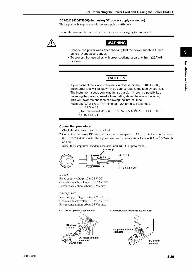
3-29IM DC100-01E
3
Installatio
n an
d W
iring
DC100/DS400/DS600(when using DC power supply connecter)This applies only to products with power supply 2 suffix code.
Follow the warnings below to avoid electric shock or damaging the instrument.
WARNING
• Connect the power wires after checking that the power supply is turnedoff to prevent electric shock.
• To prevent fire, use wires with cross sectional area of 0.3mm2(22AWG)or more.
CAUTION
• If you connect the + and - terminals in reverse on the DS400/DS600,the internal fuse will be blown (You cannot replace the fuse by yourself.The instrument needs servicing in this case). If there is a possibility ofreversing the polarity, insert a fuse (rating shown below) in the wiring.This will lower the chances of blowing the internal fuse.Fuse: 250 V/T2.5 A to T4A (time lag), 20 mm glass tube fuse,
I2t = 12.5 to 32(Recommended: A1350EF (250 V/T2.5 A, I2t=12.5: SCHURTER:FST0034.3121))
Connecting procedure1. Check thst the power switch is turned off.2. Connect the accessory DC power terminal connector (part No. A1105JC) to the power wire and
the DC100/DS400/DS600. Use a power wire with a cross sectional area of 0.3 mm2 (22AWG)or more.Install the clamp filter (standard accessory) near DC100 of power wire.
21
Soldering
- (0 V DC)
+ (10 to 32 V DC)
DC100Rated supply voltage: 12 to 28 V DCOperating supply voltage: 10 to 32 V DCPower consumption: About 30 VA max.
DS400/DS600Rated supply voltage: 12 to 28 V DCOperating supply voltage: 10 to 32 V DCPower consumption: About 25 VA max.
DC power terminal connector
DC power terminal
• DC100: DC power supply model • DS400/DS600: DC power supply model
DC power terminal connector
DC power terminalClamp filter
3.9 Connecting the Power Cord and Turning the Power ON/OFF
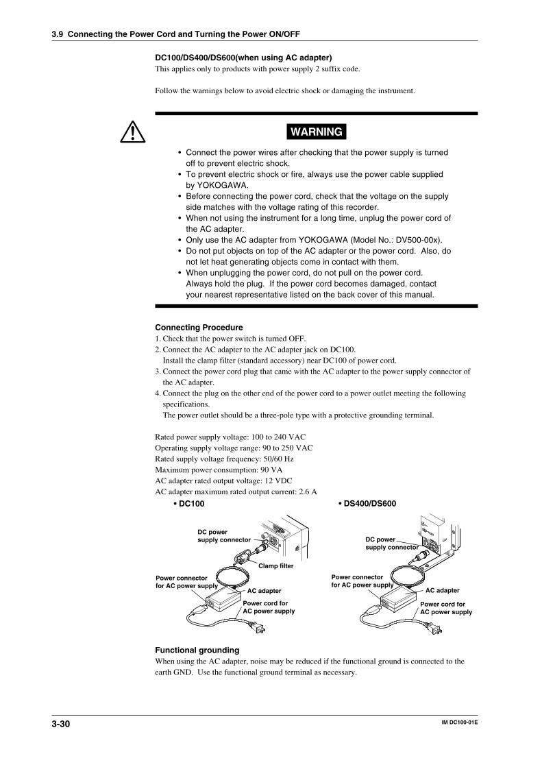
3-30 IM DC100-01E
DC100/DS400/DS600(when using AC adapter)This applies only to products with power supply 2 suffix code.
Follow the warnings below to avoid electric shock or damaging the instrument.
WARNING
• Connect the power wires after checking that the power supply is turnedoff to prevent electric shock.
• To prevent electric shock or fire, always use the power cable suppliedby YOKOGAWA.
• Before connecting the power cord, check that the voltage on the supplyside matches with the voltage rating of this recorder.
• When not using the instrument for a long time, unplug the power cord ofthe AC adapter.
• Only use the AC adapter from YOKOGAWA (Model No.: DV500-00x).• Do not put objects on top of the AC adapter or the power cord. Also, do
not let heat generating objects come in contact with them.• When unplugging the power cord, do not pull on the power cord.
Always hold the plug. If the power cord becomes damaged, contactyour nearest representative listed on the back cover of this manual.
Connecting Procedure1. Check that the power switch is turned OFF.2. Connect the AC adapter to the AC adapter jack on DC100.
Install the clamp filter (standard accessory) near DC100 of power cord.3. Connect the power cord plug that came with the AC adapter to the power supply connector of
the AC adapter.4. Connect the plug on the other end of the power cord to a power outlet meeting the following
specifications.The power outlet should be a three-pole type with a protective grounding terminal.
Rated power supply voltage: 100 to 240 VACOperating supply voltage range: 90 to 250 VACRated supply voltage frequency: 50/60 HzMaximum power consumption: 90 VAAC adapter rated output voltage: 12 VDCAC adapter maximum rated output current: 2.6 A
Power cord for AC power supply
• DC100 • DS400/DS600
DC power supply connector
AC adapter
Power connector for AC power supply
DC power supply connector
AC adapter
Power cord for AC power supply
Power connector for AC power supply
Clamp filter
Functional groundingWhen using the AC adapter, noise may be reduced if the functional ground is connected to theearth GND. Use the functional ground terminal as necessary.
3.9 Connecting the Power Cord and Turning the Power ON/OFF
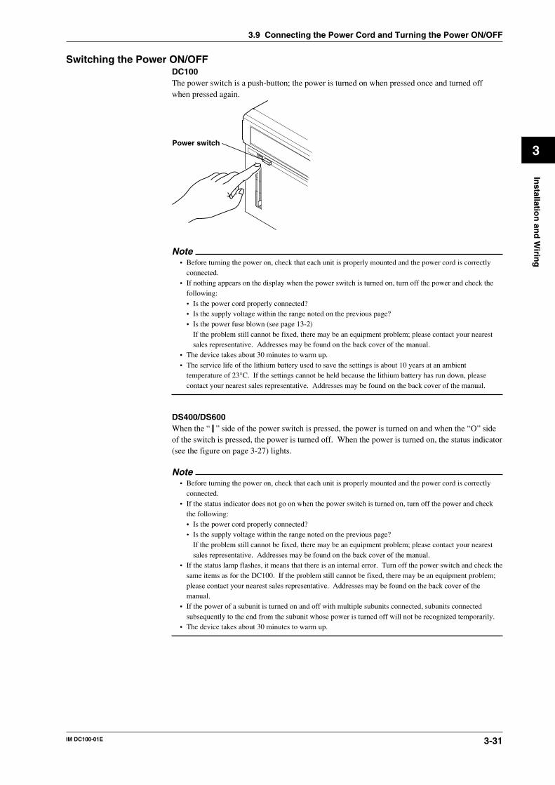
3-31IM DC100-01E
3
Installatio
n an
d W
iring
Switching the Power ON/OFFDC100The power switch is a push-button; the power is turned on when pressed once and turned offwhen pressed again.
Power switch
Note• Before turning the power on, check that each unit is properly mounted and the power cord is correctly
connected.• If nothing appears on the display when the power switch is turned on, turn off the power and check the
following:• Is the power cord properly connected?• Is the supply voltage within the range noted on the previous page?• Is the power fuse blown (see page 13-2)
If the problem still cannot be fixed, there may be an equipment problem; please contact your nearestsales representative. Addresses may be found on the back cover of the manual.
• The device takes about 30 minutes to warm up.• The service life of the lithium battery used to save the settings is about 10 years at an ambient
temperature of 23°C. If the settings cannot be held because the lithium battery has run down, pleasecontact your nearest sales representative. Addresses may be found on the back cover of the manual.
DS400/DS600When the “ ” side of the power switch is pressed, the power is turned on and when the “O” sideof the switch is pressed, the power is turned off. When the power is turned on, the status indicator(see the figure on page 3-27) lights.
Note• Before turning the power on, check that each unit is properly mounted and the power cord is correctly
connected.• If the status indicator does not go on when the power switch is turned on, turn off the power and check
the following:• Is the power cord properly connected?• Is the supply voltage within the range noted on the previous page?
If the problem still cannot be fixed, there may be an equipment problem; please contact your nearestsales representative. Addresses may be found on the back cover of the manual.
• If the status lamp flashes, it means that there is an internal error. Turn off the power switch and check thesame items as for the DC100. If the problem still cannot be fixed, there may be an equipment problem;please contact your nearest sales representative. Addresses may be found on the back cover of themanual.
• If the power of a subunit is turned on and off with multiple subunits connected, subunits connectedsubsequently to the end from the subunit whose power is turned off will not be recognized temporarily.
• The device takes about 30 minutes to warm up.
3.9 Connecting the Power Cord and Turning the Power ON/OFF
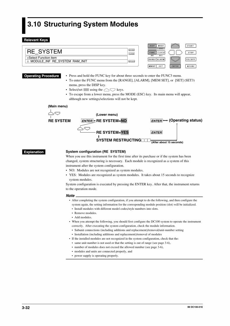
3-32 IM DC100-01E
3.10 Structuring System Modules
D I S P M O D E
C L O C KF U N C
I N S D E L
R A N G E A L A R M
S E TMEM SET E N T E R
S T O P
F D C O P Y
M. F U N C
RECORD
ALARM
KEYLOCK
S T A R T
RE_SYSTEM>Select Function item
E S C
↓ MODULE_INF RE_SYSTEM RAM_INIT
• Press and hold the FUNC key for about three seconds to enter the FUNC3 menu.• To enter the FUNC menu from the [RANGE], [ALARM], [MEM SET], or [SET] (SET3)
menu, press the DISP key.• Select/set using the keys.• To escape from a lower menu, press the MODE (ESC) key. Its main menu will appear,
although new settings/selections will not be kept.
RE SYSTEM RE SYSTEM=NO
RE SYSTEM=YES
SYSTEM RESTRUCTING
(Operating status)ENTER
ENTER
(After about 15 seconds)
ENTER
(Main menu)
(Lower menu)
System configuration (RE SYSTEM)When you use this instrument for the first time after its purchase or if the system has beenchanged, system structuring is necessary. Each module is recognized as a system of thisinstrument after the system configuration.• NO: Modules are not recognized as system modules.• YES: Modules are recognized as system modules. It takes about 15 seconds to recognize
system modules.System configuration is executed by pressing the ENTER key. After that, the instrument returnsto the operation mode.
Note• After completing the system configuration, if you attempt to do the following, and then configure the
system again, the setting information for the corresponding module position (slot) will be initialized.• Install modules with different model codes/style numbers into slots.• Remove modules.• Add modules.
• When you attempt the following, you should first configure the DC100 system to operate the instrumentcorrectly. After executing the system configuration, check the module information.• Subunit connections (including additions and replacement)/removal/unit-number setting• Installation (including additions and replacement)/removal of modules
• If the installed modules are not recognized in the system configuration, check that the:• same unit number is not used or that the setting is out of range (see page 3-6),• number of modules does not exceed the allowed number (see page 3-6),• modules and units are connected properly, and• power supply is operating properly.
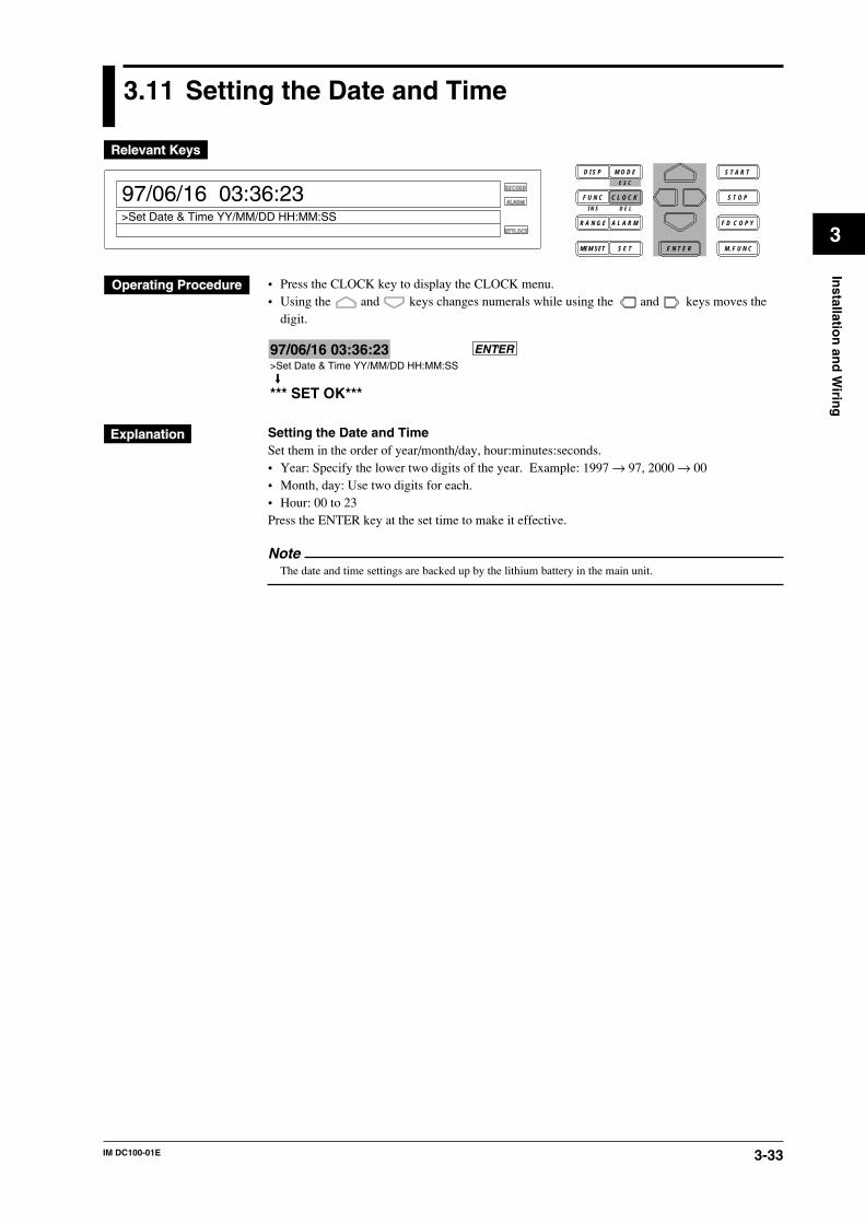
3-33IM DC100-01E
3
Installatio
n an
d W
iring
3.11 Setting the Date and Time
D I S P M O D E
C L O C KF U N C
I N S D E L
R A N G E A L A R M
S E TMEM SET E N T E R
S T O P
F D C O P Y
M. F U N C
RECORD
ALARM
KEYLOCK
S T A R T
97/06/16 03:36:23
>Set Date & Time YY/MM/DD HH:MM:SS
E S C
• Press the CLOCK key to display the CLOCK menu.• Using the and keys changes numerals while using the and keys moves the
digit.
97/06/16 03:36:23>Set Date & Time YY/MM/DD HH:MM:SS
*** SET OK***
ENTER
Setting the Date and TimeSet them in the order of year/month/day, hour:minutes:seconds.• Year: Specify the lower two digits of the year. Example: 1997 → 97, 2000 → 00• Month, day: Use two digits for each.• Hour: 00 to 23Press the ENTER key at the set time to make it effective.
NoteThe date and time settings are backed up by the lithium battery in the main unit.
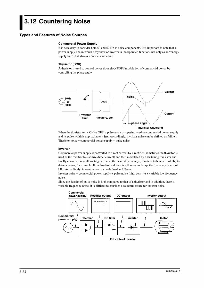
3-34 IM DC100-01E
3.12 Countering Noise
Types and Features of Noise Sources
Commercial Power SupplyIt is necessary to consider both 50 and 60 Hz as noise components. It is important to note that apower supply line in which a thyristor or inverter is incorporated functions not only as an “energysupply line”, but also as a “noise source line.”
Thyristor (SCR)A thyristor is used to control power through ON/OFF modulation of commercial power bycontrolling the phase angle.
50Hzor
60Hz
*heaters, etc.
noise
phase angle
Current
Voltage
Thyristor waveform
ThyristorUnit
*Load
When the thyristor turns ON or OFF, a pulse noise is superimposed on commercial power supply,and its pulse width is approximately 1µs. Accordingly, thyristor noise can be defined as follows.Thyristor noise = commercial power supply + pulse noise
InverterCommercial power supply is converted to direct current by a rectifier (sometimes the thyristor isused as the rectifier to stabilize direct current) and then modulated by a switching transistor andfinally converted into alternating current at the desired frequency (from tens to hundreds of Hz) todrive a motor, for example. If the load to be driven is a fluorescent lamp, the frequency is tens ofkHz. Accordingly, inverter noise can be defined as follows.Inverter noise = commercial power supply + pulse noise (high density) + variable low frequencynoiseSince the density of pulse noise is high compared to that of a thyristor and in addition, there isvariable frequency noise, it is difficult to consider a countermeasure for inverter noise.
Commercialpower supply Rectifier output DC output Inverter output
Commercialpower supply Rectifier DC filter Inverter Motor
Principle of inverter
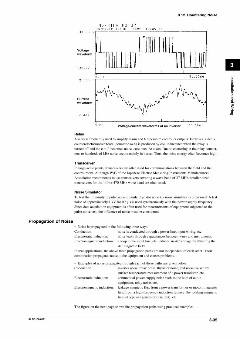
3-35IM DC100-01E
3
Installatio
n an
d W
iring
Voltage waveform
Current waveform
Voltage/current waveforms of an inverter
RelayA relay is frequently used to amplify alarm and temperature controller outputs. However, since acounterelectromotive force (counter e.m.f.) is produced by coil inductance when the relay isturned off and the e.m.f. becomes noise, care must be taken. Due to chattering at the relay contact,tens to hundreds of kHz noise occurs mainly in bursts. Thus, the noise energy often becomes high.
TransceiverIn large-scale plants, transceivers are often used for communications between the field and thecontrol room. Although W/G of the Japanese Electric Measuring Instruments ManufacturersAssociation recommends to use transceivers covering a wave band of 27 MHz, smaller-sizedtransceivers for the 140 or 470 MHz wave band are often used.
Noise SimulatorTo test the immunity to pulse noise (mainly thyristor noise), a noise simulator is often used. A testnoise of approximately 1 kV for 0.8 µs is used synchronously with the power supply frequency.Since data acquisition equipment is often used for measurements of equipment subjected to thepulse noise test, the influence of noise must be considered.
Propagation of Noise• Noise is propagated in the following three ways.Conduction: noise is conducted through a power line, input wiring, etc.Electrostatic induction: noise leaks through capacitances between wires and instruments.Electromagnetic induction: a loop in the input line, etc. induces an AC voltage by detecting the
AC magnetic field.In real applications, the above three propagation paths are not independent of each other. Theircombination propagates noise to the equipment and causes problems.
• Examples of noise propagated through each of these paths are given below.Conduction: inverter noise, relay noise, thyristor noise, and noise caused by
surface temperature measurement of a power transistor, etc.Electrostatic induction: commercial power supply noise such as the hum of audio
equipment, relay noise, etc.Electromagnetic induction: leakage magnetic flux from a power transformer or motor, magnetic
field from a high-frequency induction furnace, the rotating magneticfield of a power generator (Cu10 Ω), etc.
The figure on the next page shows the propagation paths using practical examples.
3.12 Countering Noise
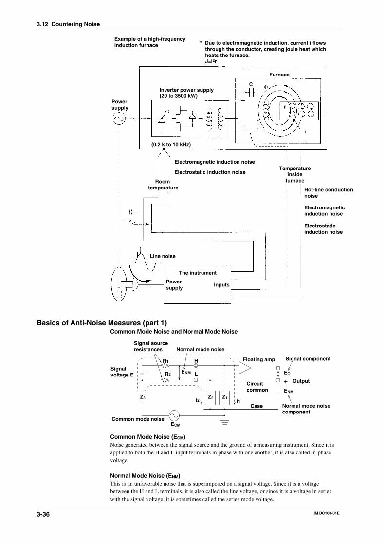
3-36 IM DC100-01E
Power supply
Example of a high-frequencyinduction furnace
Inverter power supply(20 to 3500 kW)
Furnace
C
r
i
(0.2 k to 10 kHz)
Electrostatic induction noise
Hot-line conduction noise
Electromagnetic induction noise
Electrostatic induction noise
Electromagnetic induction noise
Room temperature
Line noise
The instrument
Temperatureinside
furnace
* Due to electromagnetic induction, current i flowsthrough the conductor, creating joule heat whichheats the furnace.J=i2r
Φ
Power supply Inputs
Basics of Anti-Noise Measures (part 1)Common Mode Noise and Normal Mode Noise
R1
R2 ENM
H
L
Z2 Z1
ECM
Z3 i2 i1
EO
+ENM
Case
Circuit common
Floating amp
Signal sourceresistances Normal mode noise
Signalvoltage E
Common mode noise
Signal component
Normal mode noisecomponent
Output
Common Mode Noise (ECM)Noise generated between the signal source and the ground of a measuring instrument. Since it isapplied to both the H and L input terminals in phase with one another, it is also called in-phasevoltage.
Normal Mode Noise (ENM)This is an unfavorable noise that is superimposed on a signal voltage. Since it is a voltagebetween the H and L terminals, it is also called the line voltage, or since it is a voltage in serieswith the signal voltage, it is sometimes called the series mode voltage.
3.12 Countering Noise
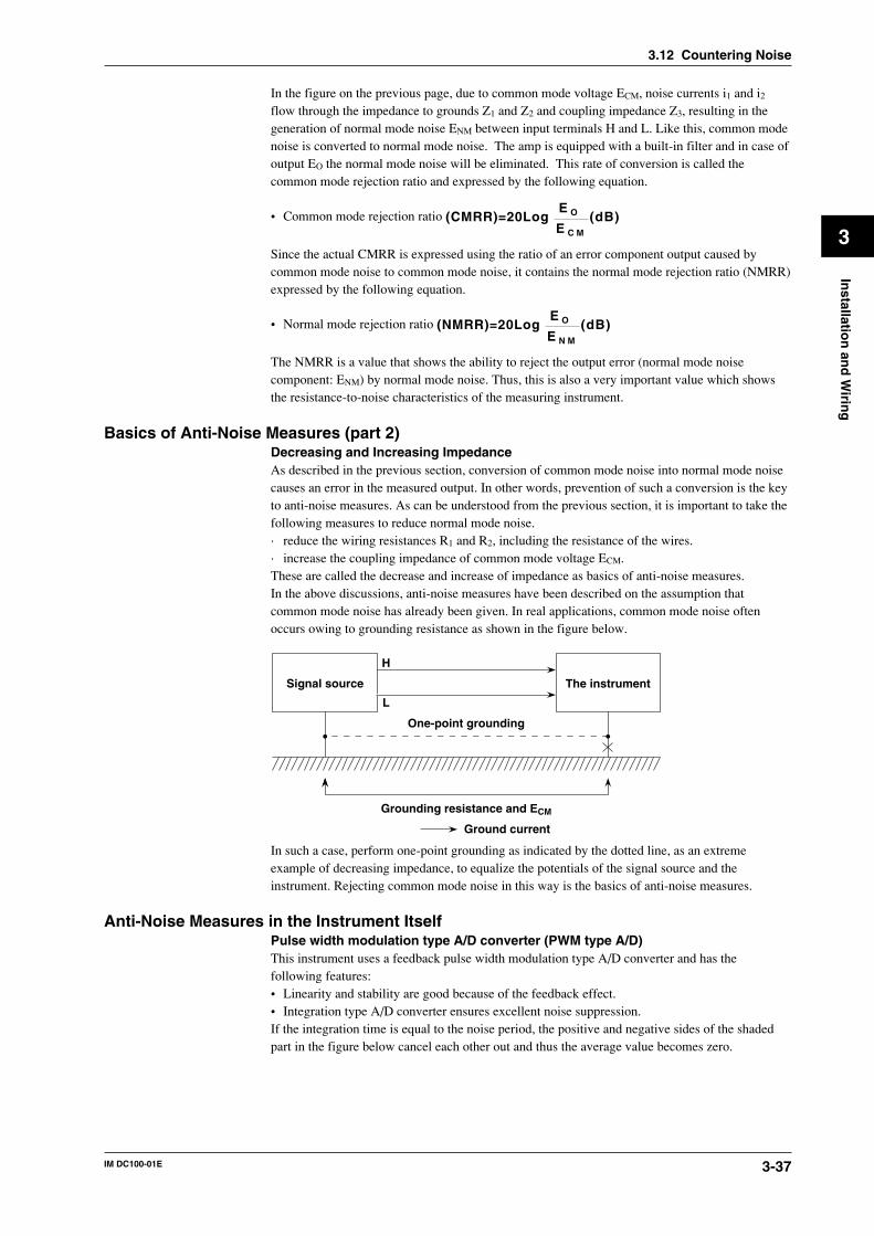
3-37IM DC100-01E
3
Installatio
n an
d W
iring
In the figure on the previous page, due to common mode voltage ECM, noise currents i1 and i2
flow through the impedance to grounds Z1 and Z2 and coupling impedance Z3, resulting in thegeneration of normal mode noise ENM between input terminals H and L. Like this, common modenoise is converted to normal mode noise. The amp is equipped with a built-in filter and in case ofoutput EO the normal mode noise will be eliminated. This rate of conversion is called thecommon mode rejection ratio and expressed by the following equation.
• Common mode rejection ratio (CMRR)=20LogE O
E C M
(dB)
Since the actual CMRR is expressed using the ratio of an error component output caused bycommon mode noise to common mode noise, it contains the normal mode rejection ratio (NMRR)expressed by the following equation.
• Normal mode rejection ratio (NMRR)=20LogE O
E N M
(dB)
The NMRR is a value that shows the ability to reject the output error (normal mode noisecomponent: ENM) by normal mode noise. Thus, this is also a very important value which showsthe resistance-to-noise characteristics of the measuring instrument.
Basics of Anti-Noise Measures (part 2)Decreasing and Increasing ImpedanceAs described in the previous section, conversion of common mode noise into normal mode noisecauses an error in the measured output. In other words, prevention of such a conversion is the keyto anti-noise measures. As can be understood from the previous section, it is important to take thefollowing measures to reduce normal mode noise.· reduce the wiring resistances R1 and R2, including the resistance of the wires.· increase the coupling impedance of common mode voltage ECM.These are called the decrease and increase of impedance as basics of anti-noise measures.In the above discussions, anti-noise measures have been described on the assumption thatcommon mode noise has already been given. In real applications, common mode noise oftenoccurs owing to grounding resistance as shown in the figure below.
Signal source The instrument
H
L
One-point grounding
Grounding resistance and ECM
Ground current
In such a case, perform one-point grounding as indicated by the dotted line, as an extremeexample of decreasing impedance, to equalize the potentials of the signal source and theinstrument. Rejecting common mode noise in this way is the basics of anti-noise measures.
Anti-Noise Measures in the Instrument ItselfPulse width modulation type A/D converter (PWM type A/D)This instrument uses a feedback pulse width modulation type A/D converter and has thefollowing features:• Linearity and stability are good because of the feedback effect.• Integration type A/D converter ensures excellent noise suppression.If the integration time is equal to the noise period, the positive and negative sides of the shadedpart in the figure below cancel each other out and thus the average value becomes zero.
3.12 Countering Noise
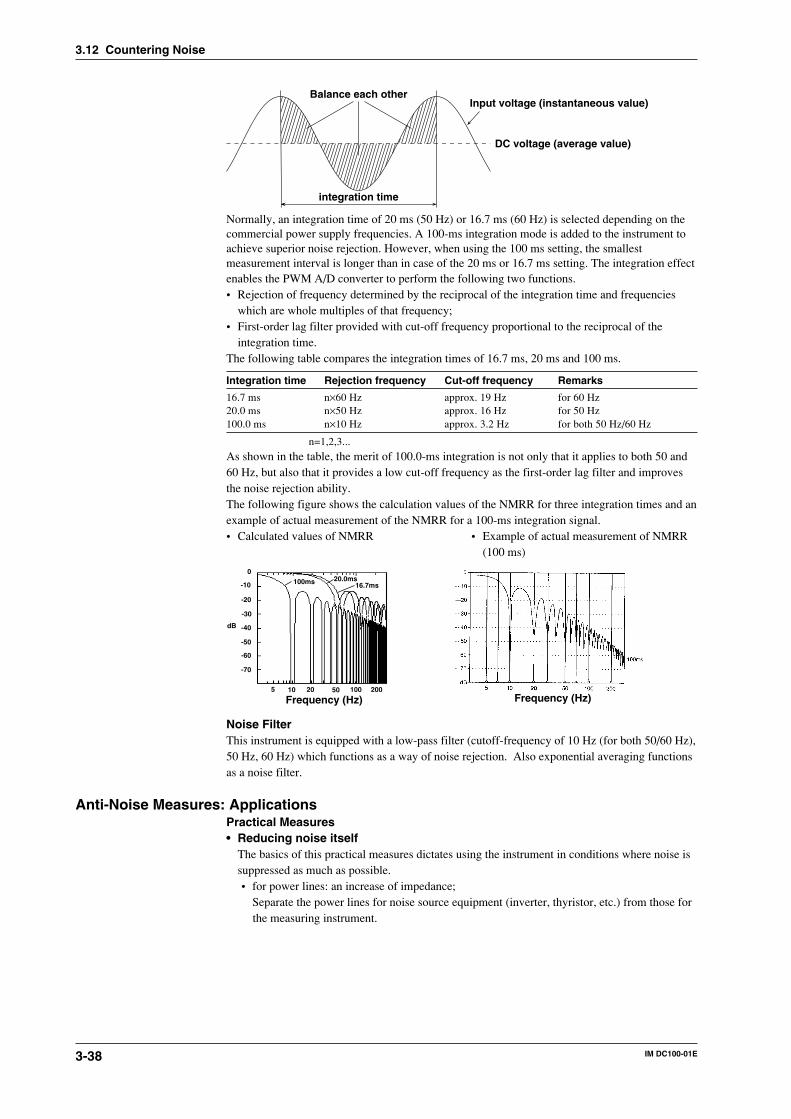
3-38 IM DC100-01E
Balance each other
integration time
DC voltage (average value)
Input voltage (instantaneous value)
Normally, an integration time of 20 ms (50 Hz) or 16.7 ms (60 Hz) is selected depending on thecommercial power supply frequencies. A 100-ms integration mode is added to the instrument toachieve superior noise rejection. However, when using the 100 ms setting, the smallestmeasurement interval is longer than in case of the 20 ms or 16.7 ms setting. The integration effectenables the PWM A/D converter to perform the following two functions.• Rejection of frequency determined by the reciprocal of the integration time and frequencies
which are whole multiples of that frequency;• First-order lag filter provided with cut-off frequency proportional to the reciprocal of the
integration time.The following table compares the integration times of 16.7 ms, 20 ms and 100 ms.
Integration time Rejection frequency Cut-off frequency Remarks
16.7 ms n×60 Hz approx. 19 Hz for 60 Hz20.0 ms n×50 Hz approx. 16 Hz for 50 Hz100.0 ms n×10 Hz approx. 3.2 Hz for both 50 Hz/60 Hz
n=1,2,3...
As shown in the table, the merit of 100.0-ms integration is not only that it applies to both 50 and60 Hz, but also that it provides a low cut-off frequency as the first-order lag filter and improvesthe noise rejection ability.The following figure shows the calculation values of the NMRR for three integration times and anexample of actual measurement of the NMRR for a 100-ms integration signal.• Calculated values of NMRR • Example of actual measurement of NMRR
(100 ms)
0
-20
-40
-60
-10
-30
-50
-70
5 10 20 50 100 200
Frequency (Hz)
dB
16.7ms20.0ms100ms
Frequency (Hz)
Noise FilterThis instrument is equipped with a low-pass filter (cutoff-frequency of 10 Hz (for both 50/60 Hz),50 Hz, 60 Hz) which functions as a way of noise rejection. Also exponential averaging functionsas a noise filter.
Anti-Noise Measures: ApplicationsPractical Measures• Reducing noise itself
The basics of this practical measures dictates using the instrument in conditions where noise issuppressed as much as possible.• for power lines: an increase of impedance;
Separate the power lines for noise source equipment (inverter, thyristor, etc.) from those forthe measuring instrument.
3.12 Countering Noise
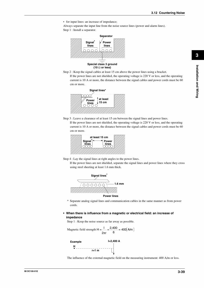
3-39IM DC100-01E
3
Installatio
n an
d W
iring
• for input lines: an increase of impedance;Always separate the input line from the noise source lines (power and alarm lines).Step 1 : Install a separator.
Separator
Special class 3 ground(10 Ω or less)
Signal*
linesPowerlines
Step 2 : Keep the signal cables at least 15 cm above the power lines using a bracket.If the power lines are not shielded, the operating voltage is 220 V or less, and the operatingcurrent is 10 A or more, the distance between the signal cables and power cords must be 60cm or more.
Signal lines*
Powerlines
at least 15 cm
Step 3 : Leave a clearance of at least 15 cm between the signal lines and power lines.If the power lines are not shielded, the operating voltage is 220 V or less, and the operatingcurrent is 10 A or more, the distance between the signal cables and power cords must be 60cm or more.
Signal*lines
Powerlines
at least 15 cm
Step 4 : Lay the signal lines at right angles to the power lines.If the power lines are not shielded, separate the signal lines and power lines where they crossusing steel sheeting at least 1.6 mm thick.
Signal lines*
Power lines
1.6 mm
* Separate analog signal lines and communication cables in the same manner as from powercords.
• When there is influence from a magnetic or electrical field: an increase ofimpedanceStep 1 : Keep the noise source as far away as possible.
Magnetic field strength H = I
2πr= 2,400
6= 400 A/m
Example I=2,400 A
r=1 mH
The influence of the external magnetic field on the measuring instrument: 400 A/m or less.
3.12 Countering Noise
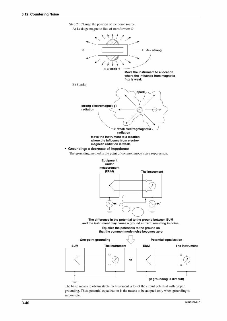
3-40 IM DC100-01E
Step 2 : Change the position of the noise source.A) Leakage magnetic flux of transformer: Φ
Φ = strong
Φ = weakMove the instrument to a location where the influence from magneticflux is weak.
B) Sparks
strong electromagneticradiation
weak electrogmagneticradiation
Move the instrument to a locationwhere the influence from electro-magnetic radiation is weak.
spark
• Grounding: a decrease of impedanceThe grounding method is the point of common mode noise suppression.
Equipmentunder
measurement(EUM) The instrument
ec ec'
EUM The instrument EUM The instrument
(if grounding is difficult)
or
The difference in the potential to the ground between EUMand the instrument may cause a ground current, resulting in noise.
Equalize the potentials to the ground so that the common mode noise becomes zero.
One-point grounding Potential equalization
The basic means to obtain stable measurement is to set the circuit potential with propergrounding. Thus, potential equalization is the means to be adopted only when grounding isimpossible.
3.12 Countering Noise
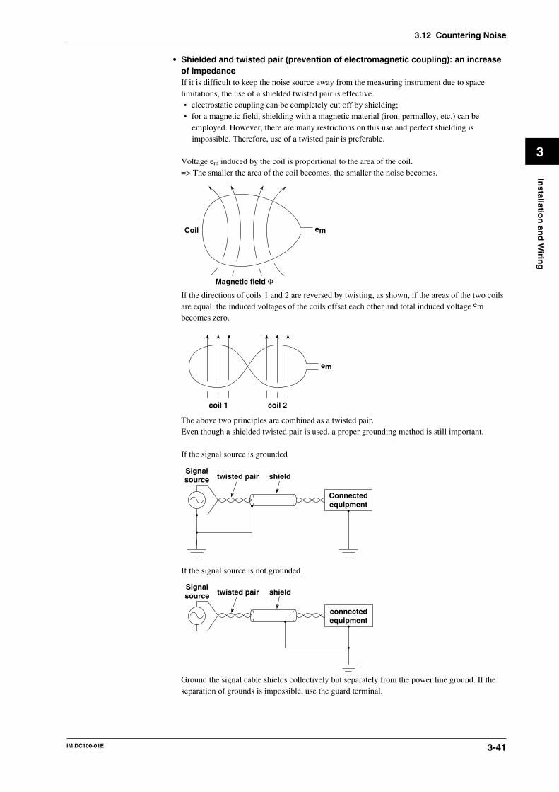
3-41IM DC100-01E
3
Installatio
n an
d W
iring
3.12 Countering Noise
• Shielded and twisted pair (prevention of electromagnetic coupling): an increaseof impedanceIf it is difficult to keep the noise source away from the measuring instrument due to spacelimitations, the use of a shielded twisted pair is effective.• electrostatic coupling can be completely cut off by shielding;• for a magnetic field, shielding with a magnetic material (iron, permalloy, etc.) can be
employed. However, there are many restrictions on this use and perfect shielding isimpossible. Therefore, use of a twisted pair is preferable.
Voltage em induced by the coil is proportional to the area of the coil.=> The smaller the area of the coil becomes, the smaller the noise becomes.
em
Magnetic field Φ
Coil
If the directions of coils 1 and 2 are reversed by twisting, as shown, if the areas of the two coilsare equal, the induced voltages of the coils offset each other and total induced voltage embecomes zero.
em
coil 1 coil 2
The above two principles are combined as a twisted pair.Even though a shielded twisted pair is used, a proper grounding method is still important.
If the signal source is grounded
Connectedequipment
Signalsource twisted pair shield
If the signal source is not grounded
connectedequipment
Signalsource twisted pair shield
Ground the signal cable shields collectively but separately from the power line ground. If theseparation of grounds is impossible, use the guard terminal.
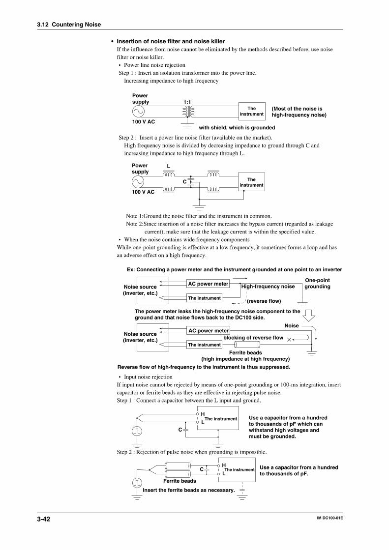
3-42 IM DC100-01E
• Insertion of noise filter and noise killerIf the influence from noise cannot be eliminated by the methods described before, use noisefilter or noise killer.• Power line noise rejectionStep 1 : Insert an isolation transformer into the power line.
Increasing impedance to high frequency
with shield, which is grounded
1:1The
instrument(Most of the noise ishigh-frequency noise)
100 V AC
Powersupply
Step 2 : Insert a power line noise filter (available on the market).High frequency noise is divided by decreasing impedance to ground through C andincreasing impedance to high frequency through L.
Theinstrument
100 V AC
L
C
Powersupply
Note 1:Ground the noise filter and the instrument in common.Note 2:Since insertion of a noise filter increases the bypass current (regarded as leakage
current), make sure that the leakage current is within the specified value.• When the noise contains wide frequency components
While one-point grounding is effective at a low frequency, it sometimes forms a loop and hasan adverse effect on a high frequency.
Ex: Connecting a power meter and the instrument grounded at one point to an inverter
AC power meter
The instrument
Noise source(inverter, etc.)
High-frequency noise
(reverse flow)
One-pointgrounding
AC power meter
The instrument
Noise
blocking of reverse flow
Ferrite beads(high impedance at high frequency)
Reverse flow of high-frequency to the instrument is thus suppressed.
The power meter leaks the high-frequency noise component to theground and that noise flows back to the DC100 side.
Noise source(inverter, etc.)
• Input noise rejectionIf input noise cannot be rejected by means of one-point grounding or 100-ms integration, insertcapacitor or ferrite beads as they are effective in rejecting pulse noise.Step 1 : Connect a capacitor between the L input and ground.
C
H
LThe instrument Use a capacitor from a hundred
to thousands of pF which canwithstand high voltages andmust be grounded.
Step 2 : Rejection of pulse noise when grounding is impossible.
CH
LThe instrument Use a capacitor from a hundred
to thousands of pF.Ferrite beads
Insert the ferrite beads as necessary.
3.12 Countering Noise
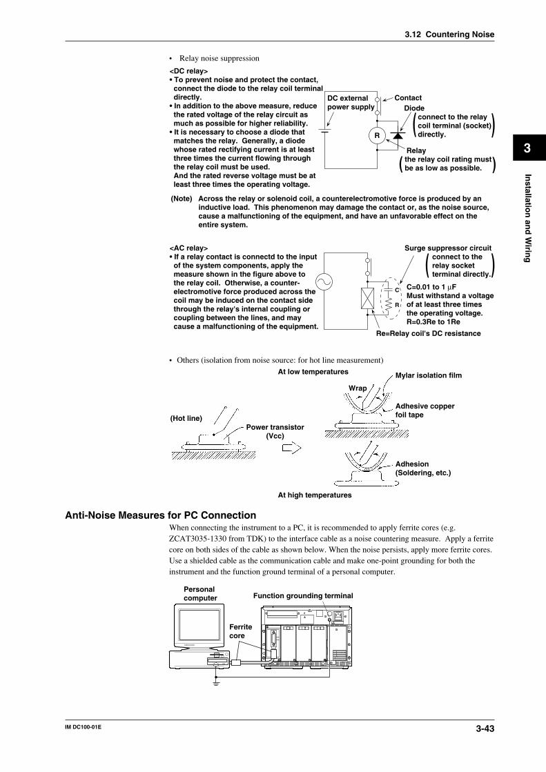
3-43IM DC100-01E
3
Installatio
n an
d W
iring
• Relay noise suppression
R
DC externalpower supply
ContactDiode
connect to the relaycoil terminal (socket)directly.
( )( )
Relaythe relay coil rating must be as low as possible.
<DC relay>• To prevent noise and protect the contact, connect the diode to the relay coil terminal directly.• In addition to the above measure, reduce the rated voltage of the relay circuit as much as possible for higher reliability.• It is necessary to choose a diode that matches the relay. Generally, a diode whose rated rectifying current is at least three times the current flowing through the relay coil must be used. And the rated reverse voltage must be at least three times the operating voltage.
(Note) Across the relay or solenoid coil, a counterelectromotive force is produced by an inductive load. This phenomenon may damage the contact or, as the noise source, cause a malfunctioning of the equipment, and have an unfavorable effect on the entire system.
Surge suppressor circuitconnect to the relay socketterminal directly.( )
C
R
C=0.01 to 1 µFMust withstand a voltageof at least three times the operating voltage.R=0.3Re to 1Re
Re=Relay coil's DC resistance
<AC relay>• If a relay contact is connectd to the input of the system components, apply the measure shown in the figure above to the relay coil. Otherwise, a counter- electromotive force produced across the coil may be induced on the contact side through the relay's internal coupling or coupling between the lines, and may cause a malfunctioning of the equipment.
• Others (isolation from noise source: for hot line measurement)
(Hot line)Power transistor
(Vcc)
Wrap
At high temperatures
At low temperatures Mylar isolation film
Adhesive copper foil tape
Adhesion(Soldering, etc.)
Anti-Noise Measures for PC ConnectionWhen connecting the instrument to a PC, it is recommended to apply ferrite cores (e.g.ZCAT3035-1330 from TDK) to the interface cable as a noise countering measure. Apply a ferritecore on both sides of the cable as shown below. When the noise persists, apply more ferrite cores.Use a shielded cable as the communication cable and make one-point grounding for both theinstrument and the function ground terminal of a personal computer.
Personalcomputer
Ferritecore
Function grounding terminal
3.12 Countering Noise
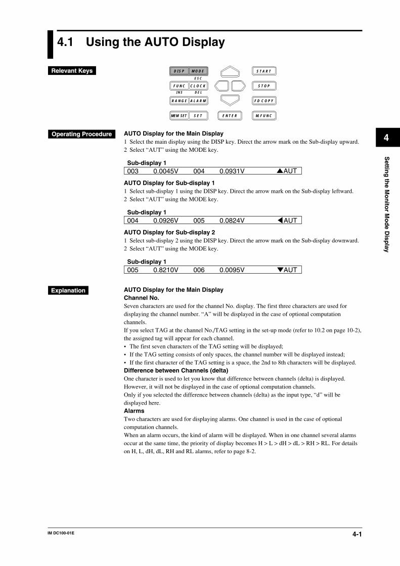
4-1IM DC100-01E
4
Settin
g th
e Mo
nito
r Mo
de D
isplay
4.1 Using the AUTO Display
D I S P M O D E
C L O C KF U N C
I N S D E L
R A N G E A L A R M
S E TMEM SET E N T E R
S T O P
F D C O P Y
M. F U N C
S T A R T
E S C
AUTO Display for the Main Display1 Select the main display using the DISP key. Direct the arrow mark on the Sub-display upward.2 Select “AUT” using the MODE key.
003 0.0045V 004 0.0931V AUTSub-display 1
AUTO Display for Sub-display 11 Select sub-display 1 using the DISP key. Direct the arrow mark on the Sub-display leftward.2 Select “AUT” using the MODE key.
004 0.0926V 005 0.0824VSub-display 1
AUT
AUTO Display for Sub-display 21 Select sub-display 2 using the DISP key. Direct the arrow mark on the Sub-display downward.2 Select “AUT” using the MODE key.
005 0.8210V 006 0.0095VSub-display 1
AUT
AUTO Display for the Main DisplayChannel No.Seven characters are used for the channel No. display. The first three characters are used fordisplaying the channel number. “A” will be displayed in the case of optional computationchannels.If you select TAG at the channel No./TAG setting in the set-up mode (refer to 10.2 on page 10-2),the assigned tag will appear for each channel.• The first seven characters of the TAG setting will be displayed;• If the TAG setting consists of only spaces, the channel number will be displayed instead;• If the first character of the TAG setting is a space, the 2nd to 8th characters will be displayed.Difference between Channels (delta)One character is used to let you know that difference between channels (delta) is displayed.However, it will not be displayed in the case of optional computation channels.Only if you selected the difference between channels (delta) as the input type, “d” will bedisplayed here.AlarmsTwo characters are used for displaying alarms. One channel is used in the case of optionalcomputation channels.When an alarm occurs, the kind of alarm will be displayed. When in one channel several alarmsoccur at the same time, the priority of display becomes H > L > dH > dL > RH > RL. For detailson H, L, dH, dL, RH and RL alarms, refer to page 8-2.
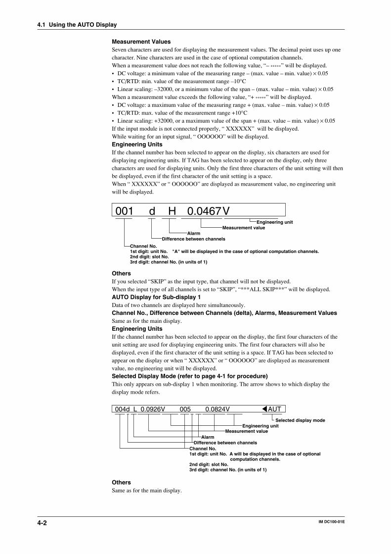
4-2 IM DC100-01E
Measurement ValuesSeven characters are used for displaying the measurement values. The decimal point uses up onecharacter. Nine characters are used in the case of optional computation channels.When a measurement value does not reach the following value, “– *****” will be displayed.• DC voltage: a minimum value of the measuring range – (max. value – min. value) × 0.05• TC/RTD: min. value of the measurement range –10°C• Linear scaling: –32000, or a minimum value of the span – (max. value – min. value) × 0.05When a measurement value exceeds the following value, “+ *****” will be displayed.• DC voltage: a maximum value of the measuring range + (max. value – min. value) × 0.05• TC/RTD: max. value of the measurement range +10°C• Linear scaling: +32000, or a maximum value of the span + (max. value – min. value) × 0.05If the input module is not connected properly, “ XXXXXX” will be displayed.While waiting for an input signal, “ OOOOOO” will be displayed.Engineering UnitsIf the channel number has been selected to appear on the display, six characters are used fordisplaying engineering units. If TAG has been selected to appear on the display, only threecharacters are used for displaying units. Only the first three characters of the unit setting will thenbe displayed, even if the first character of the unit setting is a space.When “ XXXXXX” or “ OOOOOO” are displayed as measurement value, no engineering unitwill be displayed.
001 Engineering unit
V0.0467 H dMeasurement value
AlarmDifference between channels
"A" will be displayed in the case of optional computation channels.Channel No.1st digit: unit No.2nd digit: slot No.3rd digit: channel No. (in units of 1)
OthersIf you selected “SKIP” as the input type, that channel will not be displayed.When the input type of all channels is set to “SKIP”, “***ALL SKIP***” will be displayed.AUTO Display for Sub-display 1Data of two channels are displayed here simultaneously.Channel No., Difference between Channels (delta), Alarms, Measurement ValuesSame as for the main display.Engineering UnitsIf the channel number has been selected to appear on the display, the first four characters of theunit setting are used for displaying engineering units. The first four characters will also bedisplayed, even if the first character of the unit setting is a space. If TAG has been selected toappear on the display or when “ XXXXXX” or “ OOOOOO” are displayed as measurementvalue, no engineering unit will be displayed.Selected Display Mode (refer to page 4-1 for procedure)This only appears on sub-display 1 when monitoring. The arrow shows to which display thedisplay mode refers.
004d L 0.0926V 005 0.0824V AUT
Selected display modeEngineering unit
Measurement valueAlarm
Difference between channelsChannel No.1st digit: unit No. A will be displayed in the case of optional
computation channels.2nd digit: slot No.3rd digit: channel No. (in units of 1)
OthersSame as for the main display.
4.1 Using the AUTO Display
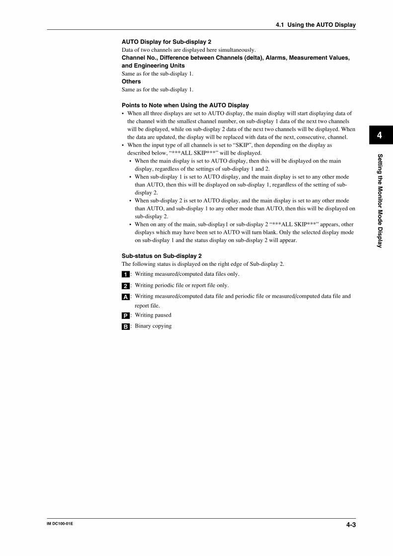
4-3IM DC100-01E
4
Settin
g th
e Mo
nito
r Mo
de D
isplay
AUTO Display for Sub-display 2Data of two channels are displayed here simultaneously.Channel No., Difference between Channels (delta), Alarms, Measurement Values,and Engineering UnitsSame as for the sub-display 1.OthersSame as for the sub-display 1.
Points to Note when Using the AUTO Display• When all three displays are set to AUTO display, the main display will start displaying data of
the channel with the smallest channel number, on sub-display 1 data of the next two channelswill be displayed, while on sub-display 2 data of the next two channels will be displayed. Whenthe data are updated, the display will be replaced with data of the next, consecutive, channel.
• When the input type of all channels is set to “SKIP”, then depending on the display asdescribed below, “***ALL SKIP***” will be displayed.• When the main display is set to AUTO display, then this will be displayed on the main
display, regardless of the settings of sub-display 1 and 2.• When sub-display 1 is set to AUTO display, and the main display is set to any other mode
than AUTO, then this will be displayed on sub-display 1, regardless of the setting of sub-display 2.
• When sub-display 2 is set to AUTO display, and the main display is set to any other modethan AUTO, and sub-display 1 to any other mode than AUTO, then this will be displayed onsub-display 2.
• When on any of the main, sub-display1 or sub-display 2 “***ALL SKIP***” appears, otherdisplays which may have been set to AUTO will turn blank. Only the selected display modeon sub-display 1 and the status display on sub-display 2 will appear.
Sub-status on Sub-display 2The following status is displayed on the right edge of Sub-display 2.
1 : Writing measured/computed data files only.
2 : Writing periodic file or report file only.
A : Writing measured/computed data file and periodic file or measured/computed data file and
report file.
P : Writing paused
B : Binary copying
4.1 Using the AUTO Display
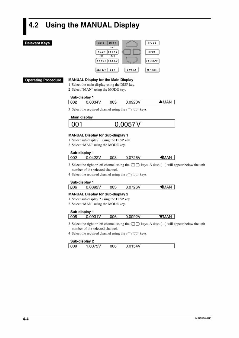
4-4 IM DC100-01E
4.2 Using the MANUAL Display
D I S P M O D E
C L O C KF U N C
I N S D E L
R A N G E A L A R M
S E TMEM SET E N T E R
S T O P
F D C O P Y
M. F U N C
S T A R T
E S C
MANUAL Display for the Main Display1 Select the main display using the DISP key.2 Select “MAN” using the MODE key.
002 0.0034V 003 0.0920V MANSub-display 1
3 Select the required channel using the keys.
001 V0.0057Main display
MANUAL Display for Sub-display 11 Select sub-display 1 using the DISP key.2 Select “MAN” using the MODE key.
002 0.0422V 003 0.0726VSub-display 1
MAN
3 Select the right or left channel using the keys. A dash [—] will appear below the unitnumber of the selected channel.
4 Select the required channel using the keys.
006 0.0892V 003 0.0726VSub-display 1
MAN
MANUAL Display for Sub-display 21 Select sub-display 2 using the DISP key.2 Select “MAN” using the MODE key.
005 0.0931V 006 0.0092VSub-display 1
MAN
3 Select the right or left channel using the keys. A dash [—] will appear below the unitnumber of the selected channel.
4 Select the required channel using the keys.
009 1.0075V 008 0.0154VSub-display 2
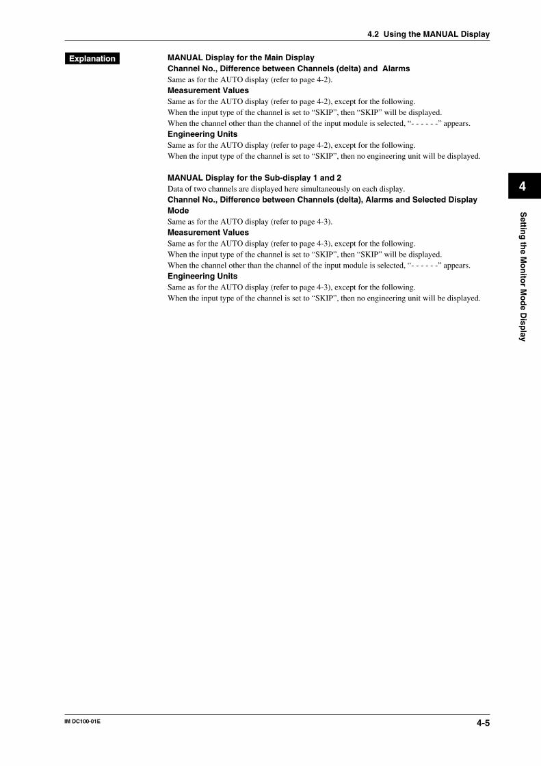
4-5IM DC100-01E
4
Settin
g th
e Mo
nito
r Mo
de D
isplay
4.2 Using the MANUAL Display
MANUAL Display for the Main DisplayChannel No., Difference between Channels (delta) and AlarmsSame as for the AUTO display (refer to page 4-2).Measurement ValuesSame as for the AUTO display (refer to page 4-2), except for the following.When the input type of the channel is set to “SKIP”, then “SKIP” will be displayed.When the channel other than the channel of the input module is selected, “- - - - - -” appears.Engineering UnitsSame as for the AUTO display (refer to page 4-2), except for the following.When the input type of the channel is set to “SKIP”, then no engineering unit will be displayed.
MANUAL Display for the Sub-display 1 and 2Data of two channels are displayed here simultaneously on each display.Channel No., Difference between Channels (delta), Alarms and Selected DisplayModeSame as for the AUTO display (refer to page 4-3).Measurement ValuesSame as for the AUTO display (refer to page 4-3), except for the following.When the input type of the channel is set to “SKIP”, then “SKIP” will be displayed.When the channel other than the channel of the input module is selected, “- - - - - -” appears.Engineering UnitsSame as for the AUTO display (refer to page 4-3), except for the following.When the input type of the channel is set to “SKIP”, then no engineering unit will be displayed.
4-6 IM DC100-01E
4.3 Using the PAGE Display
D I S P M O D E
C L O C KF U N C
I N S D E L
R A N G E A L A R M
S E TMEM SET E N T E R
S T O P
F D C O P Y
M. F U N C
S T A R T
E S C
1 Select the main display using the DISP key.2 Select “PGE” using the MODE key.
002 0.1936V 003 0.0995V PGESub-display 1
3 Select the required set of five channels (page) using the keys.
007 0.0197V 008 0.0074V PGE006 V0.0173009 0.0162V 010 0.0102V
Display
PAGE Display for the Main DisplayWhen this display is selected, the measurement values of five consecutive channels will bedisplayed using sub-display 1 and 2 also.Channel No., Difference between Channels (delta) and AlarmsSame as for the AUTO display (refer to page 4-2).Measurement ValuesSame as for the AUTO display (refer to page 4-2), except for the following.When the input type of the channel is set to “SKIP”, then “SKIP” will be displayed.When the channel other than the channel of the input module is selected, “- - - - - -” appears.Engineering UnitsSame as for the AUTO display (refer to page 4-2), except for the following.When the input type of the channel is set to “SKIP”, then no engineering unit will be displayed.
PAGE Display for the Sub-display 1 and 2In combination with the page display of the main display, data of two channels are displayed heresimultaneously on each display. Other display modes cannot be selected.Channel No., Difference between Channels (delta), Alarms and Selected Display ModeSame as for the AUTO display (refer to page 4-3).Measurement ValuesSame as for the AUTO display (refer to page 4-3), except for the following.When the input type of the channel is set to “SKIP”, then “SKIP” will be displayed.When the channel other than the channel of the input module is selected, “- - - - - -” appears.Engineering UnitsSame as for the AUTO display (refer to page 4-3), except for the following.When the input type of the channel is set to “SKIP”, then no engineering unit will be displayed.
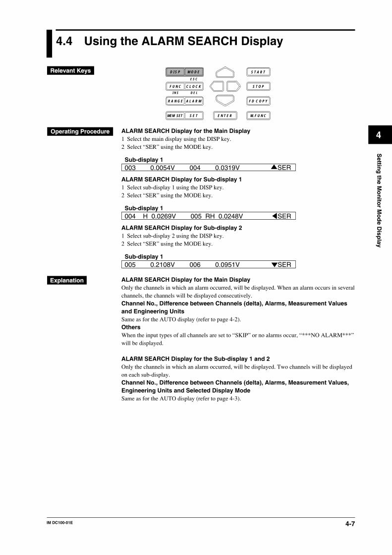
4-7IM DC100-01E
4
Settin
g th
e Mo
nito
r Mo
de D
isplay
4.4 Using the ALARM SEARCH Display
D I S P M O D E
C L O C KF U N C
I N S D E L
R A N G E A L A R M
S E TMEM SET E N T E R
S T O P
F D C O P Y
M. F U N C
S T A R T
E S C
ALARM SEARCH Display for the Main Display1 Select the main display using the DISP key.2 Select “SER” using the MODE key.
003 0.0054V 004 0.0319V SERSub-display 1
ALARM SEARCH Display for Sub-display 11 Select sub-display 1 using the DISP key.2 Select “SER” using the MODE key.
004 H 0.0269V 005 RH 0.0248VSub-display 1
SER
ALARM SEARCH Display for Sub-display 21 Select sub-display 2 using the DISP key.2 Select “SER” using the MODE key.
005 0.2108V 006 0.0951VSub-display 1
SER
ALARM SEARCH Display for the Main DisplayOnly the channels in which an alarm occurred, will be displayed. When an alarm occurs in severalchannels, the channels will be displayed consecutively.Channel No., Difference between Channels (delta), Alarms, Measurement Valuesand Engineering UnitsSame as for the AUTO display (refer to page 4-2).OthersWhen the input types of all channels are set to “SKIP” or no alarms occur, “***NO ALARM***”will be displayed.
ALARM SEARCH Display for the Sub-display 1 and 2Only the channels in which an alarm occurred, will be displayed. Two channels will be displayedon each sub-display.Channel No., Difference between Channels (delta), Alarms, Measurement Values,Engineering Units and Selected Display ModeSame as for the AUTO display (refer to page 4-3).
4-8 IM DC100-01E
4.4 Using the ALARM SEARCH Display
Points to Note when Using the ALARM SEARCH Display• When all three displays are set to ALARM SEARCH display, the main display will start
displaying data of the channel with the smallest channel number, on sub-display 1 data of thenext two channels will be displayed, while on sub-display 2 data of the next two channels willbe displayed. When the data are updated every two seconds, the display will be replaced withdata of the next, consecutive, channel.
• When the input type of all channels is set to “SKIP”, then depending on the display settings asdescribed below, “***NO ALARM***” will be displayed.• When the main display is set to ALARM SEARCH display, then this will be displayed on
the main display, regardless of the settings of sub-display 1 and 2.• When sub-display 1 is set to ALARM SEARCH display, and the main display is set to any
other mode than ALARM SEARCH, then this will be displayed on sub-display 1, regardlessof the setting of sub-display 2.
• When sub-display 2 is set to ALARM SEARCH display, and the main display is set to anyother mode than ALARM SEARCH, and sub-display 1 to any other mode than ALARMSEARCH, then this will be displayed on sub-display 2.
• When on any of the main, sub-display1 or sub-display 2 “***NO ALARM***” appears,other displays which may have been set to ALARM SEARCH will turn blank. Only theselected display mode on sub-display 1 and the status display on sub-display 2 will appear.
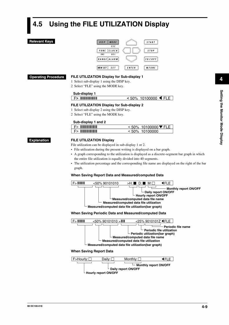
4-9IM DC100-01E
4
Settin
g th
e Mo
nito
r Mo
de D
isplay
4.5 Using the FILE UTILIZATION Display
D I S P M O D E
C L O C KF U N C
I N S D E L
R A N G E A L A R M
S E TMEM SET E N T E R
S T O P
F D C O P Y
M. F U N C
S T A R T
E S C
FILE UTILIZATION Display for Sub-display 11 Select sub-display 1 using the DISP key.2 Select “FLE” using the MODE key.
F> < 50% 10100000Sub-display 1
FLE
FILE UTILIZATION Display for Sub-display 21 Select sub-display 2 using the DISP key.2 Select “FLE” using the MODE key.
Sub-display 1 and 2F> < 50% 10100000 FLEF> < 50% 10100000
FILE UTILIZATION DisplayFile utilization can be displayed in sub-display 1 or 2.• File utilization during the present writing is displayed on a bar graph.• A graph corresponding to the utilization is displayed as a discrete-segment bar graph in which
the entire file utilization is equally divided into 40 segments.• The utilization percentage and the corresponding file name are displayed on the right of the bar
graph.
When Saving Report Data and Measured/computed Data
Monthly report ON/OFFDaily report ON/OFF
Measured/computed data file nameMeasured/computed data file utilization
Measured/computed data file utilization(bar graph)
Hourly report ON/OFF
F> <50% 90101010 >H: D: M: FLE
When Saving Periodic Data and Measured/computed Data
F> <50% 90101010 > <25% 9010101Z FLE
Periodic file namePeriodic file utilization
Measured/computed data file nameMeasured/computed data file utilization
Measured/computed data file utilization(bar graph)
Periodic utilization(bar graph)
When Saving Report Data
Daily report ON/OFFMonthly report ON/OFF
Hourly report ON/OFF
F>Hourly: FLEDaily: Monthly:
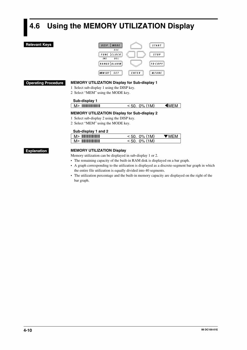
4-10 IM DC100-01E
4.6 Using the MEMORY UTILIZATION Display
D I S P M O D E
C L O C KF U N C
I N S D E L
R A N G E A L A R M
S E TMEM SET E N T E R
S T O P
F D C O P Y
M. F U N C
S T A R T
E S C
MEMORY UTILIZATION Display for Sub-display 11 Select sub-display 1 using the DISP key.2 Select “MEM” using the MODE key.
M> < 50. 0% (1M) Sub-display 1
MEM
MEMORY UTILIZATION Display for Sub-display 21 Select sub-display 2 using the DISP key.2 Select “MEM” using the MODE key.
M> < 50. 0% (1M) Sub-display 1 and 2
MEMM> < 50. 0% (1M)
MEMORY UTILIZATION DisplayMemory utilization can be displayed in sub-display 1 or 2.• The remaining capacity of the built-in RAM disk is displayed on a bar graph.• A graph corresponding to the utilization is displayed as a discrete-segment bar graph in which
the entire file utilization is equally divided into 40 segments.• The utilization percentage and the built-in memory capacity are displayed on the right of the
bar graph.
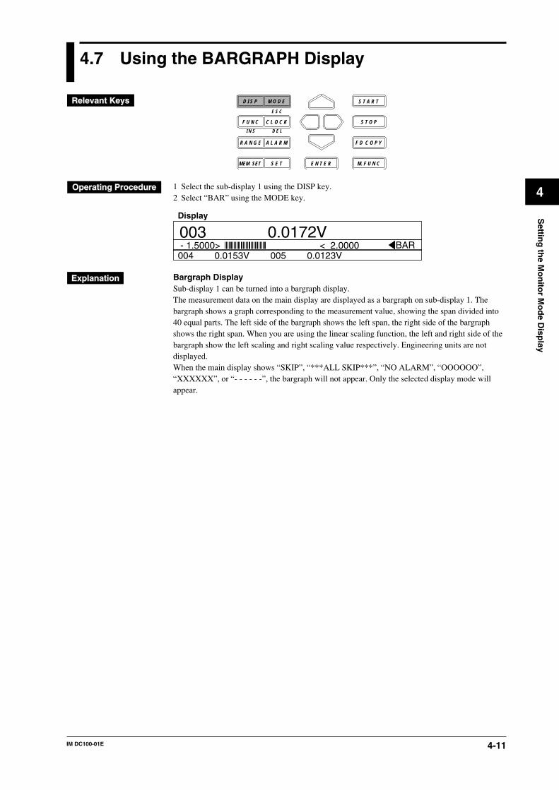
4-11IM DC100-01E
4
Settin
g th
e Mo
nito
r Mo
de D
isplay
4.7 Using the BARGRAPH Display
D I S P M O D E
C L O C KF U N C
I N S D E L
R A N G E A L A R M
S E TMEM SET E N T E R
S T O P
F D C O P Y
M. F U N C
S T A R T
E S C
1 Select the sub-display 1 using the DISP key.2 Select “BAR” using the MODE key.
- 1.5000> < 2.0000 BAR003 V0.0172004 0.0153V 005 0.0123V
Display
Bargraph DisplaySub-display 1 can be turned into a bargraph display.The measurement data on the main display are displayed as a bargraph on sub-display 1. Thebargraph shows a graph corresponding to the measurement value, showing the span divided into40 equal parts. The left side of the bargraph shows the left span, the right side of the bargraphshows the right span. When you are using the linear scaling function, the left and right side of thebargraph show the left scaling and right scaling value respectively. Engineering units are notdisplayed.When the main display shows “SKIP”, “***ALL SKIP***”, “NO ALARM”, “OOOOOO”,“XXXXXX”, or “- - - - - -”, the bargraph will not appear. Only the selected display mode willappear.
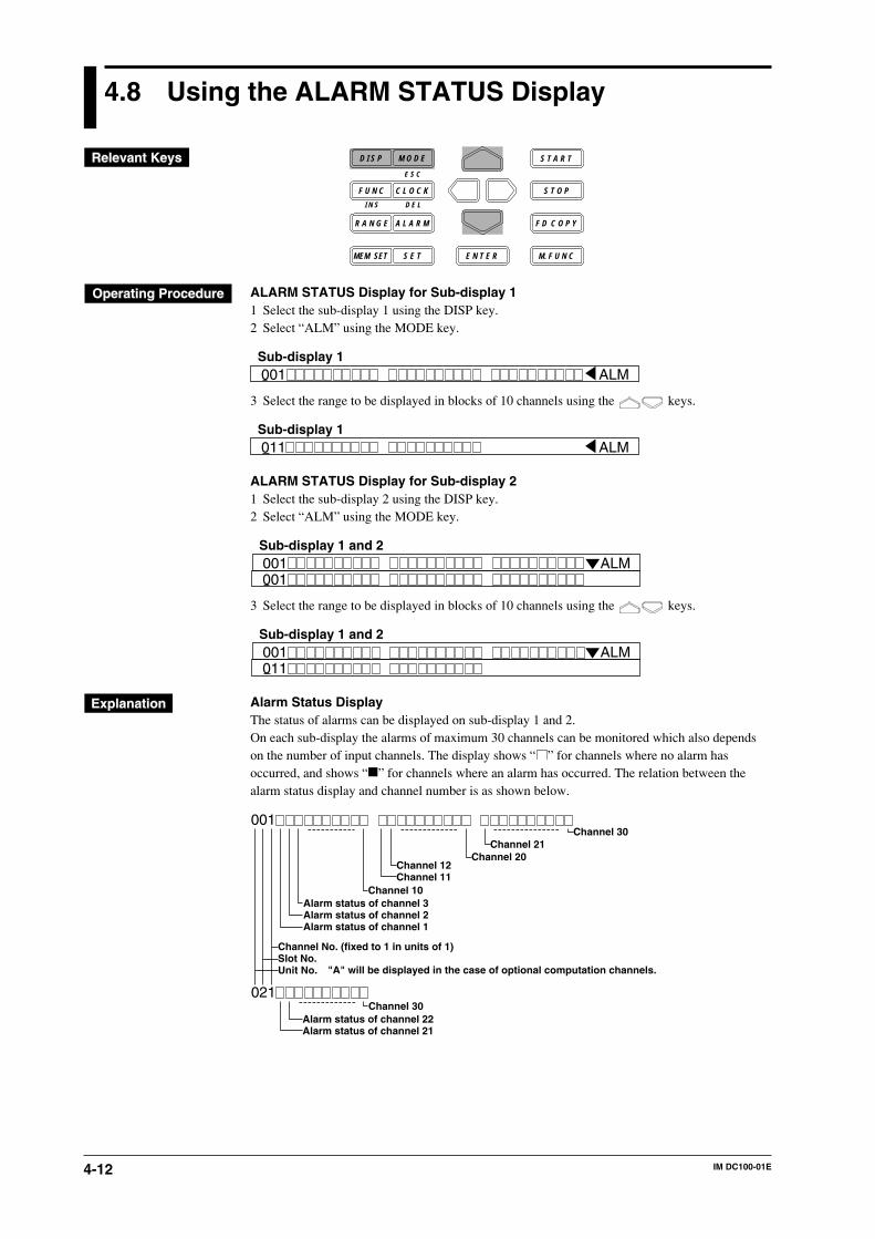
4-12 IM DC100-01E
4.8 Using the ALARM STATUS Display
D I S P M O D E
C L O C KF U N C
I N S D E L
R A N G E A L A R M
S E TMEM SET E N T E R
S T O P
F D C O P Y
M. F U N C
S T A R T
E S C
ALARM STATUS Display for Sub-display 11 Select the sub-display 1 using the DISP key.2 Select “ALM” using the MODE key.
001Sub-display 1
ALM
3 Select the range to be displayed in blocks of 10 channels using the keys.
011Sub-display 1
ALM
ALARM STATUS Display for Sub-display 21 Select the sub-display 2 using the DISP key.2 Select “ALM” using the MODE key.
001Sub-display 1 and 2
ALM001
3 Select the range to be displayed in blocks of 10 channels using the keys.
001Sub-display 1 and 2
ALM011
Alarm Status DisplayThe status of alarms can be displayed on sub-display 1 and 2.On each sub-display the alarms of maximum 30 channels can be monitored which also dependson the number of input channels. The display shows “ ” for channels where no alarm hasoccurred, and shows “ ” for channels where an alarm has occurred. The relation between thealarm status display and channel number is as shown below.
001
021
Alarm status of channel 3Alarm status of channel 2Alarm status of channel 1
Channel 12Channel 11
Channel 30Channel 21
Channel 20
Channel 10
Alarm status of channel 22Alarm status of channel 21
Channel 30
"A" will be displayed in the case of optional computation channels.
Channel No. (fixed to 1 in units of 1)Slot No.Unit No.
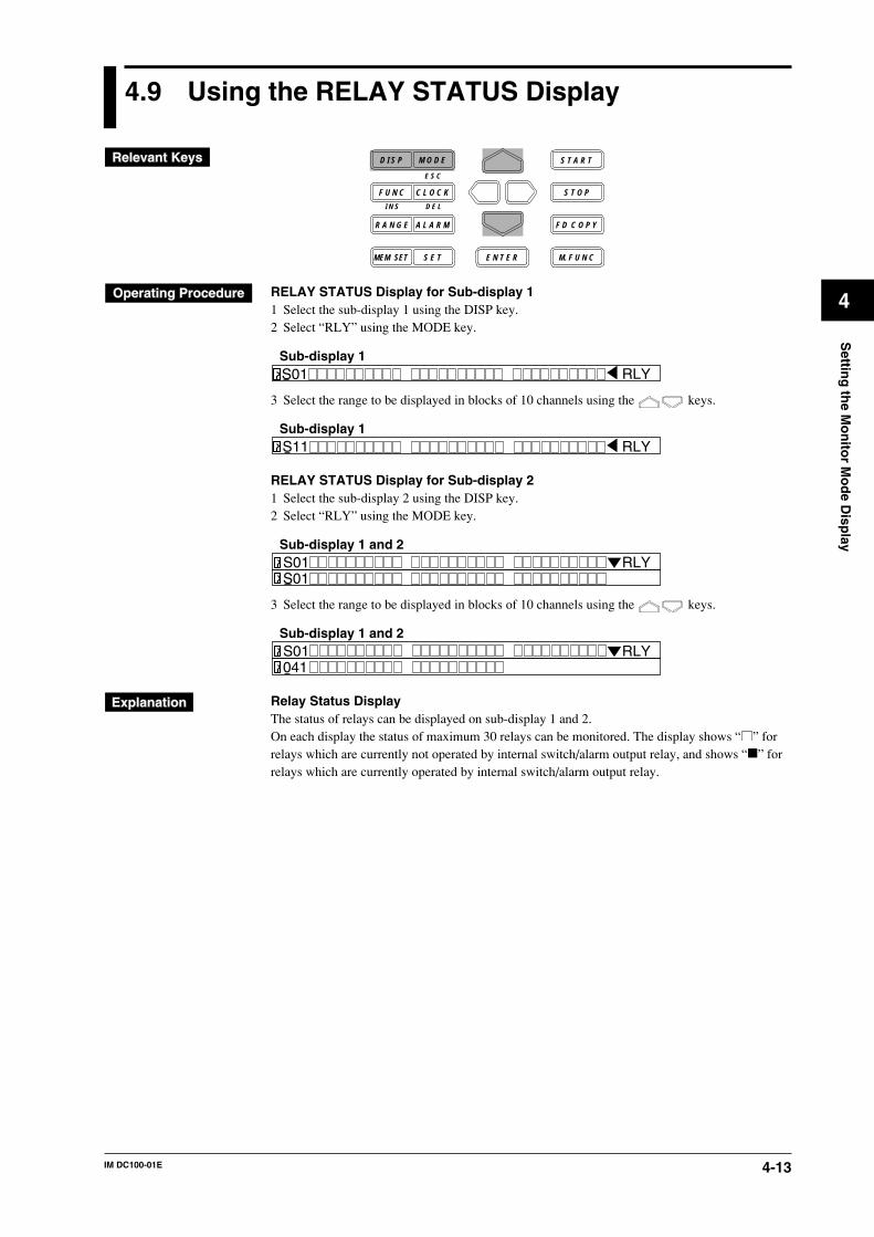
4-13IM DC100-01E
4
Settin
g th
e Mo
nito
r Mo
de D
isplay
4.9 Using the RELAY STATUS Display
D I S P M O D E
C L O C KF U N C
I N S D E L
R A N G E A L A R M
S E TMEM SET E N T E R
S T O P
F D C O P Y
M. F U N C
S T A R T
E S C
RELAY STATUS Display for Sub-display 11 Select the sub-display 1 using the DISP key.2 Select “RLY” using the MODE key.
S01Sub-display 1
RLY
3 Select the range to be displayed in blocks of 10 channels using the keys.
S11Sub-display 1
RLY
RELAY STATUS Display for Sub-display 21 Select the sub-display 2 using the DISP key.2 Select “RLY” using the MODE key.
S01Sub-display 1 and 2
RLYS01
3 Select the range to be displayed in blocks of 10 channels using the keys.
S01Sub-display 1 and 2
RLY041
Relay Status DisplayThe status of relays can be displayed on sub-display 1 and 2.On each display the status of maximum 30 relays can be monitored. The display shows “ ” forrelays which are currently not operated by internal switch/alarm output relay, and shows “ ” forrelays which are currently operated by internal switch/alarm output relay.
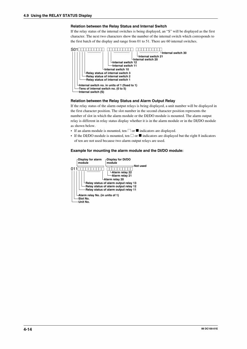
4-14 IM DC100-01E
Relation between the Relay Status and Internal SwitchIf the relay status of the internal switches is being displayed, an “S” will be displayed as the firstcharacter. The next two characters show the number of the internal switch which corresponds tothe first batch of the display and range from 01 to 51. There are 60 internal switches.
S01
Relay status of internal switch 3Relay status of internal switch 2Relay status of internal switch 1
Internal switch 12Internal switch 11
Internal switch 30Internal switch 21
Internal switch 20
Internal switch 10
Internal switch no. in units of 1 (fixed to 1)Tens of internal switch no. (0 to 5)Internal switch (S)
Relation between the Relay Status and Alarm Output RelayIf the relay status of the alarm output relays is being displayed, a unit number will be displayed inthe first character position. The slot number in the second character position represents thenumber of slot in which the alarm module or the DI/DO module is mounted. The alarm outputrelay is different in relay status display whether it is in the alarm module or in the DI/DO moduleas shown below.• If an alarm module is mounted, ten or indicators are displayed.• If the DI/DO module is mounted, ten or indicators are displayed but the right 8 indicators
of ten are not used because two alarm output relays are used.
Example for mounting the alarm module and the DI/DO module:
011
Relay status of alarm output relay 13Relay status of alarm output relay 12Relay status of alarm output relay 11
Alarm relay 22Alarm relay 21
Alarm relay 20
Alarm relay No. (in units of 1)Slot No.Unit No.
Display for alarmmodule
Display for DI/DOmodule
Not used
4.9 Using the RELAY STATUS Display
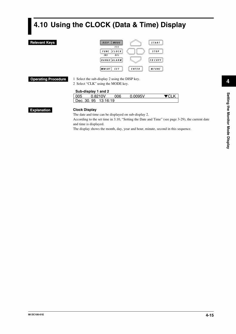
4-15IM DC100-01E
4
Settin
g th
e Mo
nito
r Mo
de D
isplay
4.10 Using the CLOCK (Data & Time) Display
D I S P M O D E
C L O C KF U N C
I N S D E L
R A N G E A L A R M
S E TMEM SET E N T E R
S T O P
F D C O P Y
M. F U N C
S T A R T
E S C
1 Select the sub-display 2 using the DISP key.2 Select “CLK” using the MODE key.
005 0.8210V 006 0.0095VSub-display 1 and 2
CLKDec. 30. 95 13:16:19
Clock DisplayThe date and time can be displayed on sub-display 2.According to the set time in 3.10, “Setting the Date and Time” (see page 3-29), the current dateand time is displayed.The display shows the month, day, year and hour, minute, second in this sequence.
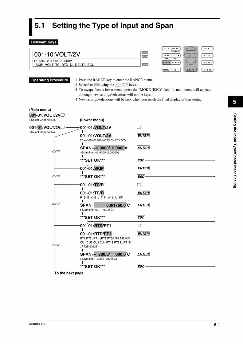
5-1IM DC100-01E
5
Settin
g th
e Inp
ut T
ype/S
pan
/Lin
ear Scalin
g
5.1 Setting the Type of Input and Span
D I S P M O D E
C L O C KF U N C
I N S D E L
R A N G E A L A R M
S E TMEM SET E N T E R
S T O P
F D C O P Y
M. F U N C
RECORD
ALARM
KEYLOCK
S T A R T
001-10:VOLT/2V
SKIP VOLT TC RTD DI DELTA SCLSPAN=–2.0000/ 2.0000V
E S C
1 Press the RANGE key to enter the RANGE menu.2 Select/set using the keys.3 To escape from a lower menu, press the “MODE (ESC)” key. Its main menu will appear,
although new settings/selections will not be kept.4 New settings/selections will be kept when you reach the final display of that setting.
001-01:VOLT/2V>Select Channel No.
001-01:VOLT/2V>Select Channel No.
001-01:VOLT/2V
001-01:VOLT/2V20mV 60mV 200mV 2V 6V 20V 50V
SPAN=–2.0000/_2.0000V>Span limit(–2.0000~2.0000V)
***SET OK***
001-01:SKIP
***SET OK***
001-01:TC/R
001-01:TC/RR S B K E J T N W L U KP
SPAN=_ _ _ _0.0/1760.0˚C>Span limit(0.0~1760.0˚C)
***SET OK***
001-01:RTD/PT1
001-01:RTD/PT1PT1 PT2 JPT1 JPT2 PT50 NI1 NI2 NI3CU1 CU2 CU3 CU4 PT1S PT2S JPT1SJPT2S J263B
SPAN=–_200.0/_ _600.0˚C>Span limit(–200.0~600.0˚C)
***SET OK***
ENTER
ENTER
ENTER
ENTER
ENTER
ENTER
ESC
ENTER
ESC
ESC
ESC
To the next page
(Main menu)
(Lower menu)
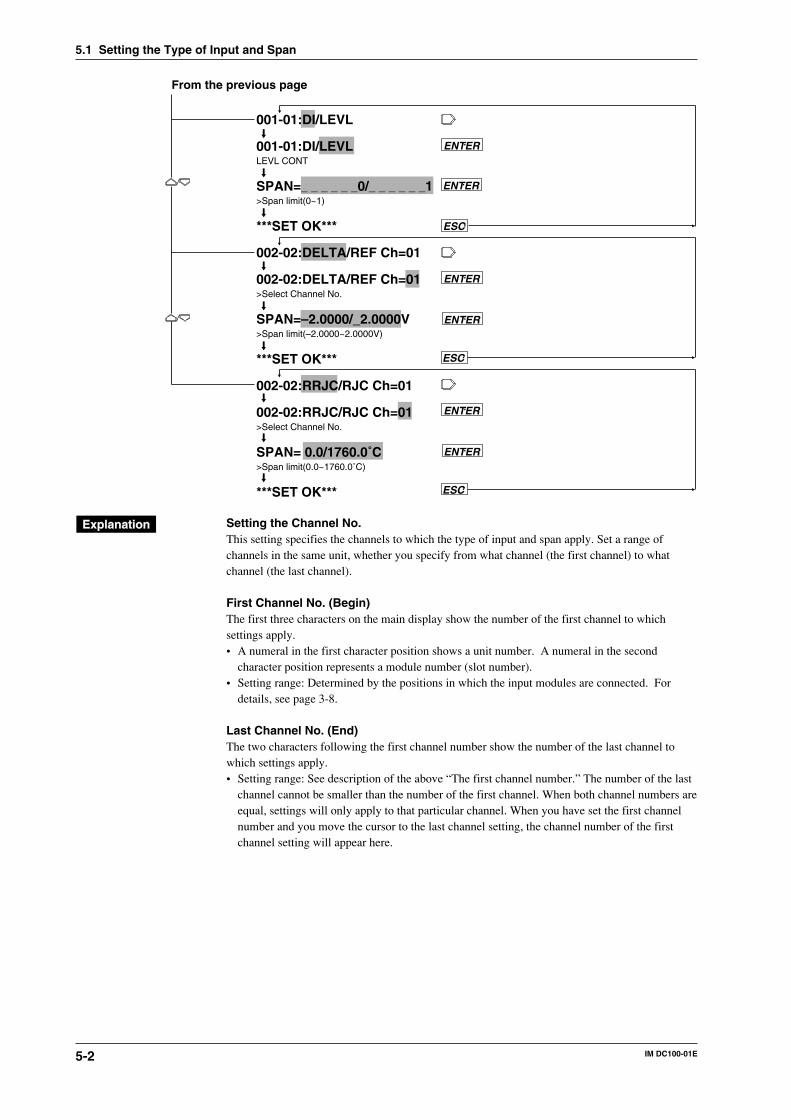
5-2 IM DC100-01E
5.1 Setting the Type of Input and Span
ENTER
ESC
ENTER
001-01:DI/LEVL
001-01:DI/LEVLLEVL CONT
SPAN=_ _ _ _ _ _0/_ _ _ _ _ _1>Span limit(0~1)
***SET OK***
002-02:DELTA/REF Ch=01
002-02:DELTA/REF Ch=01>Select Channel No.
SPAN=–2.0000/_2.0000V>Span limit(–2.0000~2.0000V)
***SET OK***
002-02:RRJC/RJC Ch=01
002-02:RRJC/RJC Ch=01>Select Channel No.
SPAN= 0.0/1760.0˚C>Span limit(0.0~1760.0˚C)
***SET OK***
ENTER
ENTER
ENTER
ESC
ESC
From the previous page
ENTER
Setting the Channel No.This setting specifies the channels to which the type of input and span apply. Set a range ofchannels in the same unit, whether you specify from what channel (the first channel) to whatchannel (the last channel).
First Channel No. (Begin)The first three characters on the main display show the number of the first channel to whichsettings apply.• A numeral in the first character position shows a unit number. A numeral in the second
character position represents a module number (slot number).• Setting range: Determined by the positions in which the input modules are connected. For
details, see page 3-8.
Last Channel No. (End)The two characters following the first channel number show the number of the last channel towhich settings apply.• Setting range: See description of the above “The first channel number.” The number of the last
channel cannot be smaller than the number of the first channel. When both channel numbers areequal, settings will only apply to that particular channel. When you have set the first channelnumber and you move the cursor to the last channel setting, the channel number of the firstchannel setting will appear here.
5-3IM DC100-01E
5
Settin
g th
e Inp
ut T
ype/S
pan
/Lin
ear Scalin
g
5.1 Setting the Type of Input and Span
Selecting the Type of InputThe following types of input can be selected. The default setting is VOLT.• SKIP
Measurement, data saving and display (except for page display) will not be carried out.Measurement, data saving and display will be carried out for the next channel whose input typeis not set to SKIP.
• VOLT (DC voltage)This input type can be selected from 20mV, 60mV, 200mV, 2V, 6V, 20V and 50V. Refer tochapter 14 for the measurement range of each setting. The default setting is 2V.
• TC (thermocouple)This input type can be selected from R, S, B, K, E, J, T, N, W, L, U and KP (KPvsAu7Fe).Refer to chapter 14 for the measurement range of each setting. The default setting is R.
• RTD (resistance temperature detector)This input type can be selected from PT1 (Pt100 1mA), PT2 (Pt100 2mA), JPT1 (JPt100 1mA),JPT2 (JPt100 2mA), PT50 (Pt50 2mA), NI1 (Ni100 1mA SAMA), NI2 (Ni100 1mA DIN), NI3(Ni120 1mA), CU1 (Cu10 GE), CU2 (Cu10 L&N), CU3 (Cu10 WEED), CU4 (Cu10BAILEY), PT1S (Pt100 1mA high resolution), PT2S (Pt100 2mA high resolution), JPT1S(JPt100 1mA high resolution), JPT2S (JPt100 2mA high resolution) and J263B (J263*B). Referto chapter 14 for the measurement range of each setting. The default setting is PT1.
• DI (voltage level: LEVL; contact:CONT)This input type can be selected from LEVL and CONT.In case of LEVL, a voltage of less than approx. 2.4 V will be recognized as “0 (OFF)”, whereasa voltage of approx. 2.4 V or more (max. allowable voltage is up to ±60 VDC) will berecognized as “1 (ON)”.In case of CONT, an open, externally connected contact to which no voltage is applied, will berecognized as “0 (OFF)”, whereas a closed contact will be recognized as “1 (ON)”.The default setting is LEVL.
• DELTA (difference between channels)Computation can be done only in the same unit. Destination channels should lie within the firstchannel No. to the last channel No. range. The number of the reference channel (REF) shouldbe lower than the number of the destination channels. The default setting for the referencechannel is 01.The type of input and the measuring range in the distination channel are the same as for thereference channel. After setting the DELTA (difference between channels), if you attempted tochange the type of input and the measuring range, setting the difference between channels isreleased, thereby the type of input and the measuring range in the destination channel arereturned to their original settings, and the span is returned to its initial value.
• RRJC (Remote RJC, available if the instrument is equipped with the optional MATH function)Reference channel (RJC): Within the setting range of reference channel No.TC (thermocouple) must be selected as the type of input to the reference channel.If the channel No. or type of input for the reference channel, or the type of thermocouple ischanged, the alarm function will be turned OFF.If the type of input for the reference channel or the type of thermocouple is changed, the RRJCsettings will be cleared and the type of input and measuring range for the reference channel willbe set to the one which was in effect before the change was made. The span will be set to theinitial value of the measuring range.
• mA (DC current, mA input module)This input can be set only for mA input channels. The measuring range is -20 mA to 20 mA.
Setting the SpanThe measurement range is decided according to the type of input. The left and right span must liewithin the measurement range. However, the span is 0 to 1 for the DI input type. By setting thespan, the setting range for the upper/lower alarm limit of the rate-of-change is determined. Thevalue on the left side of the SPAN menu shows the left span, and the value on the right side of theSPAN menu shows the right span.For the remote RJC, the setting range for span is the same as that for the reference channel.
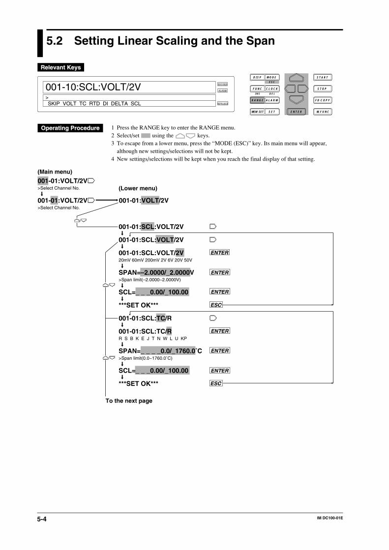
5-4 IM DC100-01E
5.2 Setting Linear Scaling and the Span
RECORD
ALARM
KEYLOCK
001-10:SCL:VOLT/2V
SKIP VOLT TC RTD DI DELTA SCL>
D I S P M O D E
C L O C KF U N C
I N S D E L
R A N G E A L A R M
S E TMEM SET E N T E R
S T O P
F D C O P Y
M. F U N C
S T A R TE S C
1 Press the RANGE key to enter the RANGE menu.2 Select/set using the keys.3 To escape from a lower menu, press the “MODE (ESC)” key. Its main menu will appear,
although new settings/selections will not be kept.4 New settings/selections will be kept when you reach the final display of that setting.
001-01:VOLT/2V>Select Channel No.
001-01:VOLT/2V>Select Channel No.
001-01:VOLT/2V
(Main menu)
(Lower menu)
001-01:SCL:VOLT/2V
001-01:SCL:VOLT/2V
001-01:SCL:VOLT/2V20mV 60mV 200mV 2V 6V 20V 50V
SPAN=–2.0000/_2.0000V>Span limit(–2.0000~2.0000V)
SCL=_ _ _0.00/_100.00
***SET OK***
001-01:SCL:TC/R
001-01:SCL:TC/RR S B K E J T N W L U KP
SPAN=_ _ _ _0.0/_1760.0˚C>Span limit(0.0~1760.0˚C)
SCL=_ _ _0.00/_100.00
***SET OK***
ENTER
ENTER
ENTER
ENTER
ESC
ESC
ENTER
ENTER
To the next page
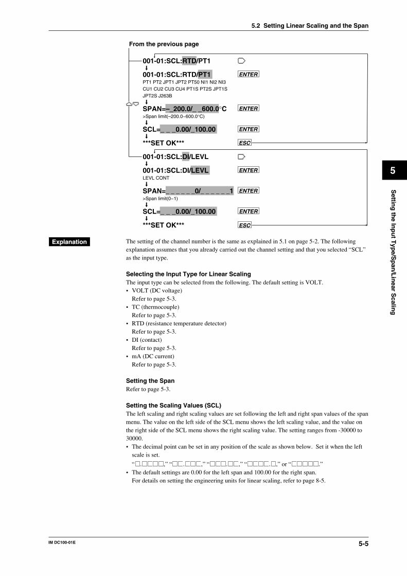
5-5IM DC100-01E
5
Settin
g th
e Inp
ut T
ype/S
pan
/Lin
ear Scalin
g
5.2 Setting Linear Scaling and the Span
001-01:SCL:RTD/PT1
001-01:SCL:RTD/PT1PT1 PT2 JPT1 JPT2 PT50 NI1 NI2 NI3CU1 CU2 CU3 CU4 PT1S PT2S JPT1SJPT2S J263B
SPAN=–_200.0/_ _600.0°C>Span limit(–200.0~600.0°C)
SCL=_ _ _0.00/_100.00
***SET OK***
001-01:SCL:DI/LEVL
001-01:SCL:DI/LEVLLEVL CONT
SPAN=_ _ _ _ _ _0/_ _ _ _ _ _1>Span limit(0~1)
SCL=_ _ _0.00/_100.00
***SET OK***
ENTER
ENTER
ENTER
ENTER
ESC
ENTER
ESC
ENTER
From the previous page
The setting of the channel number is the same as explained in 5.1 on page 5-2. The followingexplanation assumes that you already carried out the channel setting and that you selected “SCL”as the input type.
Selecting the Input Type for Linear ScalingThe input type can be selected from the following. The default setting is VOLT.• VOLT (DC voltage)
Refer to page 5-3.• TC (thermocouple)
Refer to page 5-3.• RTD (resistance temperature detector)
Refer to page 5-3.• DI (contact)
Refer to page 5-3.• mA (DC current)
Refer to page 5-3.
Setting the SpanRefer to page 5-3.
Setting the Scaling Values (SCL)The left scaling and right scaling values are set following the left and right span values of the spanmenu. The value on the left side of the SCL menu shows the left scaling value, and the value onthe right side of the SCL menu shows the right scaling value. The setting ranges from -30000 to30000.• The decimal point can be set in any position of the scale as shown below. Set it when the left
scale is set.
“ . ,” “ . ,” “ . ,” “ . ,” or “ .”• The default settings are 0.00 for the left span and 100.00 for the right span.
For details on setting the engineering units for linear scaling, refer to page 8-5.
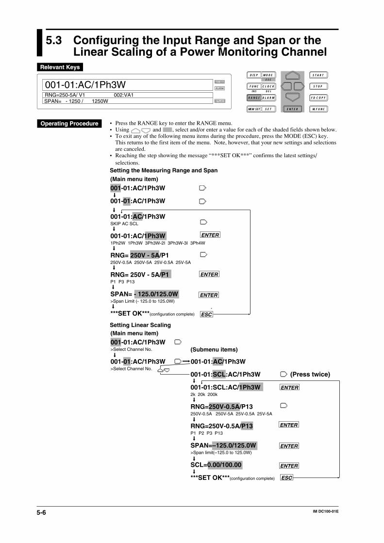
5-6 IM DC100-01E
5.3 Configuring the Input Range and Span or theLinear Scaling of a Power Monitoring Channel
RECORD
ALARM
KEYLOCK
001-01:AC/1Ph3W
SPAN= - 1250 / 1250WRNG=250-5A/ V1 002:VA1
D I S P M O D E
C L O C KF U N C
I N S D E L
R A N G E A L A R M
S E TMEM SET E N T E R
S T O P
F D C O P Y
M. F U N C
S T A R TE S C
• Press the RANGE key to enter the RANGE menu.• Using and , select and/or enter a value for each of the shaded fields shown below.• To exit any of the following menu items during the procedure, press the MODE (ESC) key.
This returns to the first item of the menu. Note, however, that your new settings and selectionsare canceled.
• Reaching the step showing the message “***SET OK***” confirms the latest settings/selections.
Setting the Measuring Range and Span
001-01:AC/1Ph3W
001-01:AC/1Ph3W
(Main menu item)
001-01:AC/1Ph3WSKIP AC SCL
001-01:AC/1Ph3W1Ph2W 1Ph3W 3Ph3W-2I 3Ph3W-3I 3Ph4W
RNG= 250V - 5A/P1250V-0.5A 250V-5A 25V-0.5A 25V-5A
RNG= 250V - 5A/P1P1 P3 P13
SPAN= - 125.0/125.0W>Span Limit (- 125.0 to 125.0W)
***SET OK***(configuration complete)
ENTER
ESC
ENTER
ENTER
Setting Linear Scaling
001-01:AC/1Ph3W>Select Channel No.
001-01:AC/1Ph3W>Select Channel No.
001-01:AC/1Ph3W
(Main menu item)
(Submenu items)
001-01:SCL:AC/1Ph3W
001-01:SCL:AC/1Ph3W2k 20k 200k
RNG=250V-0.5A/P13250V-0.5A 250V-5A 25V-0.5A 25V-5A
RNG=250V-0.5A/P13P1 P2 P3 P13
SPAN=–125.0/125.0W>Span limit(–125.0 to 125.0W)
SCL=0.00/100.00
***SET OK***(configuration complete)
ENTER
ESC
(Press twice)
ENTER
ENTER
ENTER
5-7IM DC100-01E
5
Settin
g th
e Inp
ut T
ype/S
pan
/Lin
ear Scalin
g
Setting the Channel NumberThis procedure sets the channel number for which you want to show and record the values of aparameter selected from the effective voltage, effective current, active power, reactive power,apparent power, frequency, power factor and phase angle which were calculated using themeasured data. Therefore, it does not correlate with the terminals of an input module. In thisprocedure, determine from which channel (starting channel) to which channel (ending channel)you want to include in your configuration.Starting Channel NumberThe first three digits on the main display constitute the starting channel number.• The first digit is the unit number. The second digit denotes the module number (slot number).• The configurable range depends on the location where the power monitor module is connected.
See page 3-8 for more information.Ending Channel NumberThe two digits that follow the starting channel number constitute the ending channel number.Normally, the starting channel number and the ending channel number should be the same. If youwant to skip any consecutive number of channels, enter the range of those channel numbers.• When you move the cursor from the starting to the ending channel number, the ending channel
number becomes the same as the last two digits of the starting channel number.Setting the Wiring MethodSelect from the following methods:
Single-phase two-wire (1Ph2W)Single-phase three-wire (1Ph3W; three-wire input modules only)Three-phase three-wire 2 Voltage 2 Current (3Ph3W-2I; three-wire input modules only)Three-phase three-wire 3 Voltage 3 Current (3Ph3W-3I; three-wire input module only)Three-phase four-wire (3Ph4W; three-wire input modules only)
Setting the Input RangeSelect from the following ranges:
250V-0.5A 250V-5A25V-0.5A 25V-5A
This setting is common to all channels. Any change to this setting also changes the settings of therest of the channels. Impose a voltage or current signal to the input module within the limits youset here.
NoteIf the connection method or input range is changed, alarm setting is turned off.
Setting the Parameter Being Shown and SavedA power monitor module measures the voltage or current through the respective channels. Thevalues that are shown and saved are not those of the voltage and current being actually measuredthrough each channel but the values of the parameters you set here.A combination of parameters being measured is fixed for each group of channels 1-2, 3-4 and 5-6within the same module. For example, setting channel 1 to P1 (active power 1) sets channel 2 toVA1 (apparent power 1). In addition, the configurable parameters being measured variesdepending on the wiring method selected. See the lists on the next page for more information.The respective mnemonics in the lists should be interpreted as noted below:
Vi (i=1, 2, 3) : effective voltage Ii (i=1, 2, 3) : effective currentV13 : (V1+V3)/2 I13 : (I1+I3)/2V0 : (V1+V2+V3)/3 I0 : (I1+I2+I3)/3Pi (i=1, 2, 3) : active power Vari (i=1, 2, 3) : reactive powerP13 : (P1+P3)/2 Var13 : Var1+Var3P0 : P1+P2+P3 Var 0 : Var1+Var2+Var3VAi (i=1, 2, 3) : apparent power PFi (i=1, 2, 3) : power factorVA13 : VA1+VA3 PF13 : P13/(PF132+Var132)1/2=P13/VA13VA0 : VA1+VA2+VA3 PF0 : P0/(P02+Var02)1/2=P0/VA0PHi (i=1, 2, 3) : phase FREQ : frequencyPH13 : tan–1 (Var13/P13)PH0 : tan–1 (Var0/P0)
5.3 Configuring the Input Range and Span or the Linear Scaling of a Power Monitoring Channel
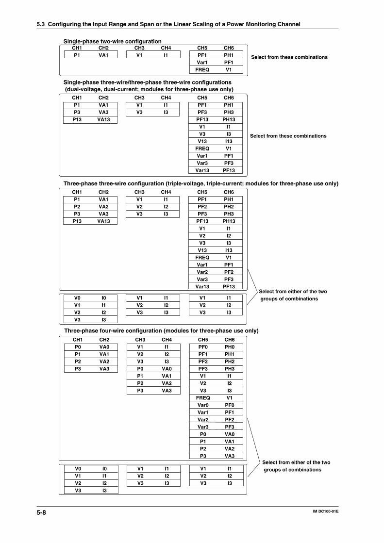
5-8 IM DC100-01E
CH1P1
CH2VA1
CH3V1
CH4I1
CH5PF1Var1
FREQ
CH6PH1PF1V1
Single-phase two-wire configuration
CH1P1P3P13
CH2VA1VA3
VA13
CH3V1V3
CH4I1I3
CH5PF1PF3
PF13V1V3
V13FREQVar1Var3
Var13
CH6PH1PH3
PH13I1I3
I13V1
PF1PF3
PF13
Single-phase three-wire/three-phase three-wire configurations (dual-voltage, dual-current; modules for three-phase use only)
CH1P1P2P3P13
CH2VA1VA2VA3
VA13
CH3V1V2V3
CH4I1I2I3
CH5PF1PF2PF3
PF13V1V2V3
V13FREQVar1Var2Var3
Var13
CH6PH1PH2PH3
PH13I1I2I3
I13V1
PF1PF2PF3
PF13
Three-phase three-wire configuration (triple-voltage, triple-current; modules for three-phase use only)
V0V1V2V3
I0I1I2I3
V1V2V3
I1I2I3
V1V2V3
I1I2I3
CH1P0P1P2P3
CH2VA0VA1VA2VA3
CH3V1V2V3P0P1P2P3
CH4I1I2I3
VA0VA1VA2VA3
CH5PF0PF1PF2PF3V1V2V3
FREQVar0Var1Var2Var3P0P1P2P3
CH6PH0PH1PH2PH3I1I2I3V1
PF0PF1PF2PF3VA0VA1VA2VA3
Three-phase four-wire configuration (modules for three-phase use only)
V0V1V2V3
I0I1I2I3
V1V2V3
I1I2I3
V1V2V3
I1I2I3
Select from these combinations
Select from these combinations
Select from either of the two groups of combinations
Select from either of the two groups of combinations
5.3 Configuring the Input Range and Span or the Linear Scaling of a Power Monitoring Channel
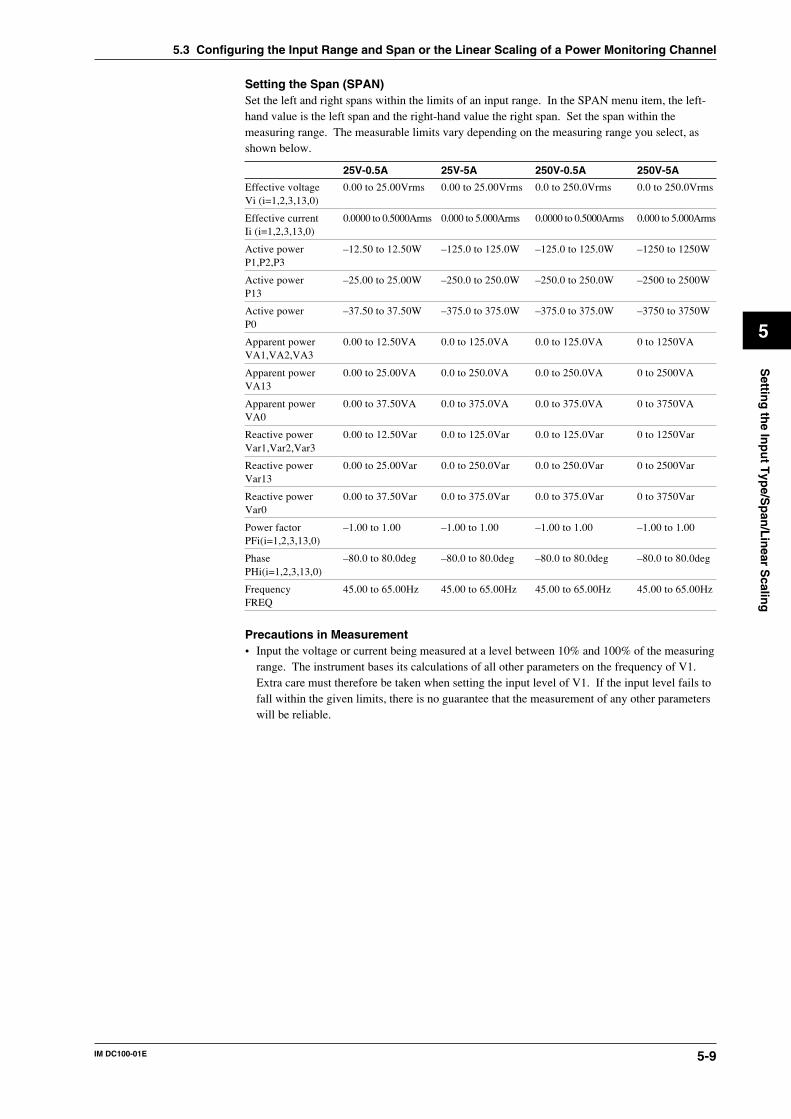
5-9IM DC100-01E
5
Settin
g th
e Inp
ut T
ype/S
pan
/Lin
ear Scalin
g
Setting the Span (SPAN)Set the left and right spans within the limits of an input range. In the SPAN menu item, the left-hand value is the left span and the right-hand value the right span. Set the span within themeasuring range. The measurable limits vary depending on the measuring range you select, asshown below.
25V-0.5A 25V-5A 250V-0.5A 250V-5A
Effective voltage 0.00 to 25.00Vrms 0.00 to 25.00Vrms 0.0 to 250.0Vrms 0.0 to 250.0VrmsVi (i=1,2,3,13,0)
Effective current 0.0000 to 0.5000Arms 0.000 to 5.000Arms 0.0000 to 0.5000Arms 0.000 to 5.000ArmsIi (i=1,2,3,13,0)
Active power –12.50 to 12.50W –125.0 to 125.0W –125.0 to 125.0W –1250 to 1250WP1,P2,P3
Active power –25.00 to 25.00W –250.0 to 250.0W –250.0 to 250.0W –2500 to 2500WP13
Active power –37.50 to 37.50W –375.0 to 375.0W –375.0 to 375.0W –3750 to 3750WP0
Apparent power 0.00 to 12.50VA 0.0 to 125.0VA 0.0 to 125.0VA 0 to 1250VAVA1,VA2,VA3
Apparent power 0.00 to 25.00VA 0.0 to 250.0VA 0.0 to 250.0VA 0 to 2500VAVA13
Apparent power 0.00 to 37.50VA 0.0 to 375.0VA 0.0 to 375.0VA 0 to 3750VAVA0
Reactive power 0.00 to 12.50Var 0.0 to 125.0Var 0.0 to 125.0Var 0 to 1250VarVar1,Var2,Var3
Reactive power 0.00 to 25.00Var 0.0 to 250.0Var 0.0 to 250.0Var 0 to 2500VarVar13
Reactive power 0.00 to 37.50Var 0.0 to 375.0Var 0.0 to 375.0Var 0 to 3750VarVar0
Power factor –1.00 to 1.00 –1.00 to 1.00 –1.00 to 1.00 –1.00 to 1.00PFi(i=1,2,3,13,0)
Phase –80.0 to 80.0deg –80.0 to 80.0deg –80.0 to 80.0deg –80.0 to 80.0degPHi(i=1,2,3,13,0)
Frequency 45.00 to 65.00Hz 45.00 to 65.00Hz 45.00 to 65.00Hz 45.00 to 65.00HzFREQ
Precautions in Measurement• Input the voltage or current being measured at a level between 10% and 100% of the measuring
range. The instrument bases its calculations of all other parameters on the frequency of V1.Extra care must therefore be taken when setting the input level of V1. If the input level fails tofall within the given limits, there is no guarantee that the measurement of any other parameterswill be reliable.
5.3 Configuring the Input Range and Span or the Linear Scaling of a Power Monitoring Channel
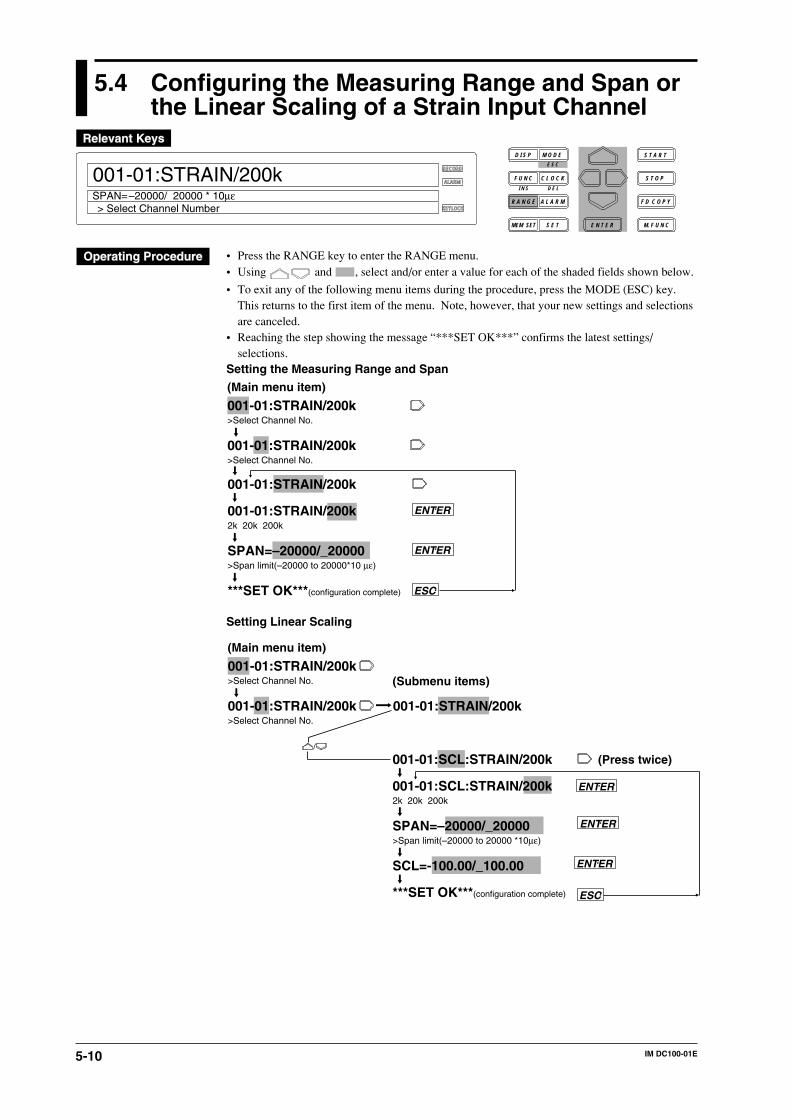
5-10 IM DC100-01E
5.4 Configuring the Measuring Range and Span orthe Linear Scaling of a Strain Input Channel
RECORD
ALARM
KEYLOCK
001-01:STRAIN/200k
> Select Channel NumberSPAN=–20000/ 20000 * 10µε
D I S P M O D E
C L O C KF U N C
I N S D E L
R A N G E A L A R M
S E TMEM SET E N T E R
S T O P
F D C O P Y
M. F U N C
S T A R TE S C
• Press the RANGE key to enter the RANGE menu.• Using and , select and/or enter a value for each of the shaded fields shown below.
• To exit any of the following menu items during the procedure, press the MODE (ESC) key.This returns to the first item of the menu. Note, however, that your new settings and selectionsare canceled.
• Reaching the step showing the message “***SET OK***” confirms the latest settings/selections.
Setting the Measuring Range and Span
001-01:STRAIN/200k>Select Channel No.
001-01:STRAIN/200k>Select Channel No.
(Main menu item)
001-01:STRAIN/200k
001-01:STRAIN/200k2k 20k 200k
SPAN=–20000/_20000>Span limit(–20000 to 20000*10 µε)
***SET OK***(configuration complete)
ENTER
ENTER
ESC
Setting Linear Scaling
001-01:STRAIN/200k>Select Channel No.
001-01:STRAIN/200k>Select Channel No.
001-01:STRAIN/200k
(Main menu item)
(Submenu items)
001-01:SCL:STRAIN/200k
001-01:SCL:STRAIN/200k2k 20k 200k
SPAN=–20000/_20000>Span limit(–20000 to 20000 *10µε)
SCL=-100.00/_100.00
***SET OK***(configuration complete)
ENTER
ESC
ENTER
(Press twice)
ENTER
5-11IM DC100-01E
5
Settin
g th
e Inp
ut T
ype/S
pan
/Lin
ear Scalin
g
Setting the Channel NumberSet the channel number for which you want to configure the type of input, span and so on. In thisprocedure, determine from which channel (starting channel) to which channel (ending channel)you want to include in your configuration.Starting Channel NumberThe first three digits on the main display constitute the starting channel number.• The first digit is the unit number. The second digit denotes the module number (slot number).• The configurable range depends on the location where the power monitor module is connected.
A strain input module takes up twice the space of a standard-size module. This results in thenumber of the slot following the one where the strain input module is installed being a missingnumber. See page 3-8 for more information.
Ending Channel NumberThe two digits that follow the starting channel number constitute the ending channel number.• For the configurable range, see “Starting Channel Number” above.• You cannot enter a channel number that is smaller than the starting channel number.• If you have entered the same number as the starting channel number, only that one particular
channel is included in your configuration (configuration of the type of input, span, etc.).• When you move the cursor from the starting to the ending channel number, the ending channel
number becomes the same as the last two digits of the starting channel number.Measurement ModeThe measurement mode should be 2 k, 20 k, or 200 k. The measuring ranges are as shown belowdepending on the measurement modes and gauge methods.
Gauge method 2 k 20 k 200 k
1-gauge method -2000 to 2000 µε -20000 to 20000 µε -200000 to 200000 µε2-gauge method -1000 to 1000 µε -10000 to 10000 µε -100000 to 100000 µε4-gauge method -500 to 500 µε -5000 to 5000 µε -50000 to 50000 µε
Setting the Span (SPAN)Set the left and right spans within the limits of the input range. In the SPAN menu item, the left-hand value is the left span and the right-hand value the right span.
NoteIf you have connected any new strain gauge or changed the measuring range (initialization of settings or
reconfiguration of the system also changes the measuring range back to its default), you must go through
initial balancing. See Section 5.5, “Performing Initial Balancing/Initialization on a Strain Input Channel,”
for more information.
5.4 Configuring the Measuring Range and Span or the Linear Scaling of a Strain Input Channel
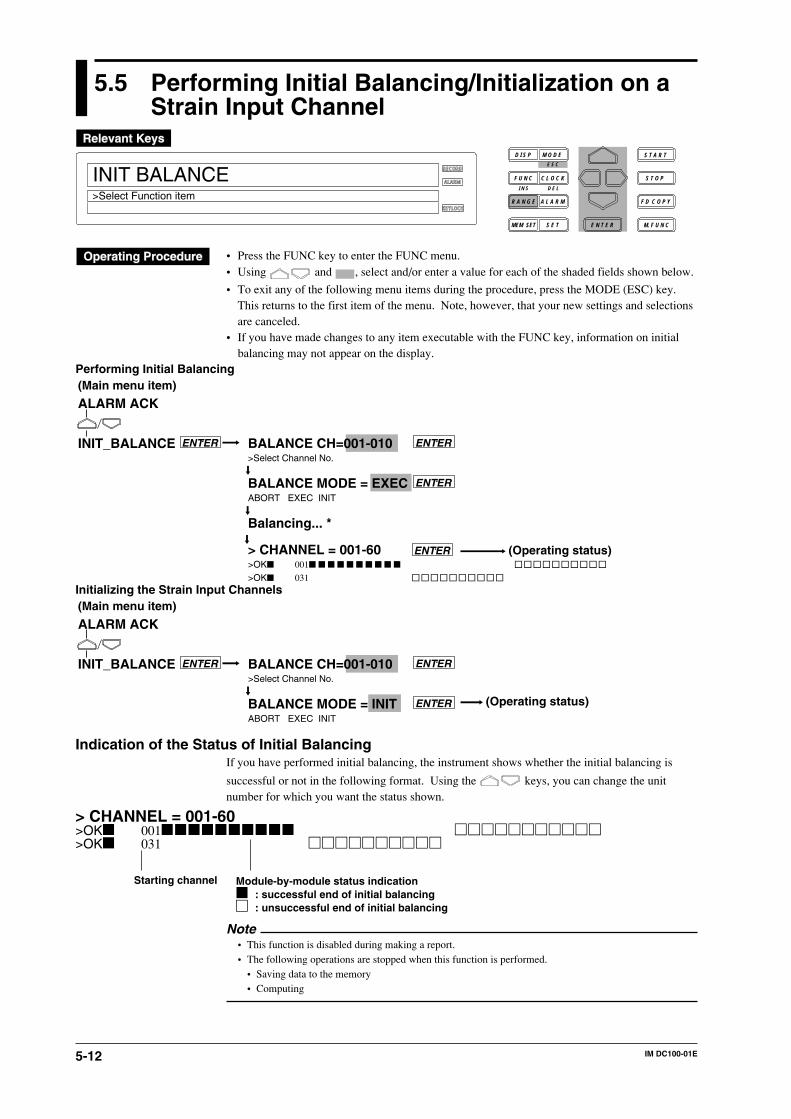
5-12 IM DC100-01E
5.5 Performing Initial Balancing/Initialization on aStrain Input Channel
RECORD
ALARM
KEYLOCK
INIT BALANCE>Select Function item
D I S P M O D E
C L O C KF U N C
I N S D E L
R A N G E A L A R M
S E TMEM SET E N T E R
S T O P
F D C O P Y
M. F U N C
S T A R TE S C
• Press the FUNC key to enter the FUNC menu.• Using and , select and/or enter a value for each of the shaded fields shown below.
• To exit any of the following menu items during the procedure, press the MODE (ESC) key.This returns to the first item of the menu. Note, however, that your new settings and selectionsare canceled.
• If you have made changes to any item executable with the FUNC key, information on initialbalancing may not appear on the display.
Performing Initial Balancing
ALARM ACK
INIT_BALANCE
(Operating status)
ENTER
(Main menu item)
BALANCE CH=001-010>Select Channel No.
BALANCE MODE = EXECABORT EXEC INIT
Balancing... *
> CHANNEL = 001-60>OK 001
>OK 031
ENTER
ENTER
ENTER
Initializing the Strain Input Channels
ALARM ACK
INIT_BALANCE
(Operating status)
ENTER
(Main menu item)
BALANCE CH=001-010>Select Channel No.
BALANCE MODE = INITABORT EXEC INIT
ENTER
ENTER
Indication of the Status of Initial BalancingIf you have performed initial balancing, the instrument shows whether the initial balancing is
successful or not in the following format. Using the keys, you can change the unitnumber for which you want the status shown.
> CHANNEL = 001-60>OK 001>OK 031
Module-by-module status indication : successful end of initial balancing : unsuccessful end of initial balancing
Starting channel
Note• This function is disabled during making a report.• The following operations are stopped when this function is performed.
• Saving data to the memory• Computing
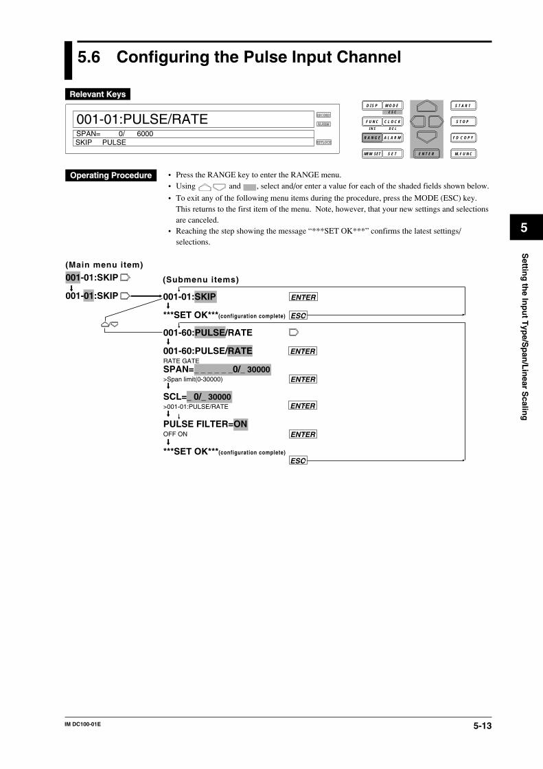
5-13IM DC100-01E
5
Settin
g th
e Inp
ut T
ype/S
pan
/Lin
ear Scalin
g
5.6 Configuring the Pulse Input Channel
RECORD
ALARM
KEYLOCK
001-01:PULSE/RATE
SKIP PULSESPAN= 0/ 6000
D I S P M O D E
C L O C KF U N C
I N S D E L
R A N G E A L A R M
S E TMEM SET E N T E R
S T O P
F D C O P Y
M. F U N C
S T A R TE S C
• Press the RANGE key to enter the RANGE menu.• Using and , select and/or enter a value for each of the shaded fields shown below.
• To exit any of the following menu items during the procedure, press the MODE (ESC) key.This returns to the first item of the menu. Note, however, that your new settings and selectionsare canceled.
• Reaching the step showing the message “***SET OK***” confirms the latest settings/selections.
001-01:SKIP
001-01:SKIP 001-01:SKIP
***SET OK***(configuration complete)
(Main menu item)
(Submenu items)
ENTER
ESC
001-60:PULSE/RATE
001-60:PULSE/RATERATE GATESPAN=_ _ _ _ _ _0/_ 30000>Span limit(0-30000)
SCL=_ 0/_ 30000>001-01:PULSE/RATE
PULSE FILTER=ONOFF ON
***SET OK***(configuration complete)
ENTER
ENTER
ENTER
ENTER
ESC
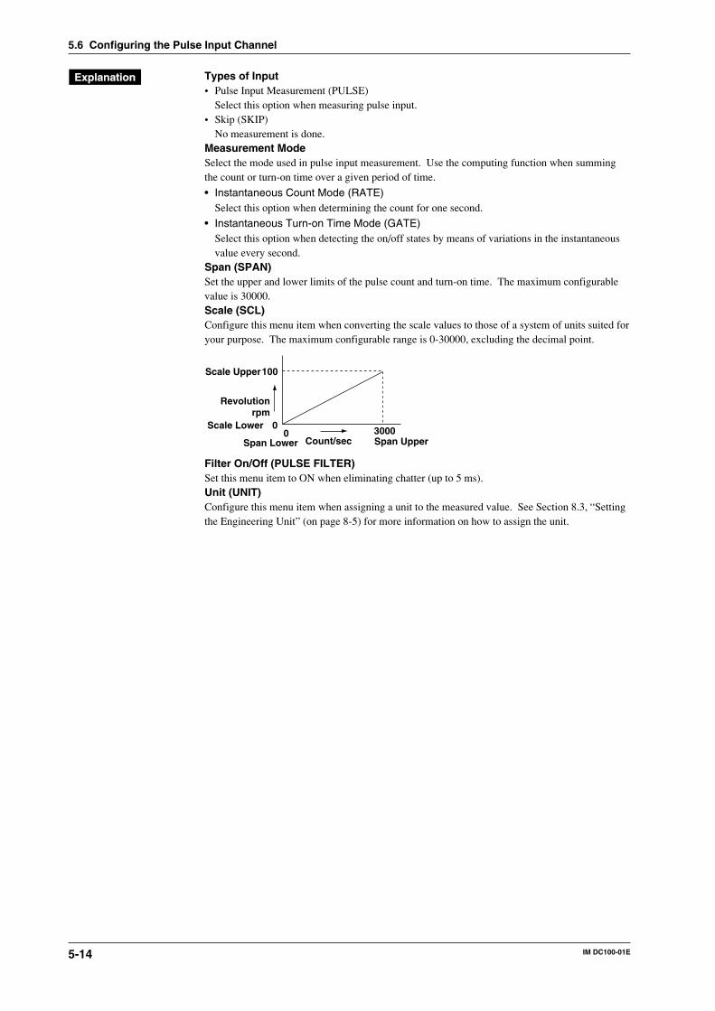
5-14 IM DC100-01E
Types of Input• Pulse Input Measurement (PULSE)
Select this option when measuring pulse input.• Skip (SKIP)
No measurement is done.Measurement ModeSelect the mode used in pulse input measurement. Use the computing function when summingthe count or turn-on time over a given period of time.
• Instantaneous Count Mode (RATE)Select this option when determining the count for one second.
• Instantaneous Turn-on Time Mode (GATE)Select this option when detecting the on/off states by means of variations in the instantaneousvalue every second.
Span (SPAN)Set the upper and lower limits of the pulse count and turn-on time. The maximum configurablevalue is 30000.Scale (SCL)Configure this menu item when converting the scale values to those of a system of units suited foryour purpose. The maximum configurable range is 0-30000, excluding the decimal point.
Count/sec0 30000
100
Revolutionrpm
Span Lower
Scale Lower
Span Upper
Scale Upper
Filter On/Off (PULSE FILTER)Set this menu item to ON when eliminating chatter (up to 5 ms).Unit (UNIT)Configure this menu item when assigning a unit to the measured value. See Section 8.3, “Settingthe Engineering Unit” (on page 8-5) for more information on how to assign the unit.
5.6 Configuring the Pulse Input Channel
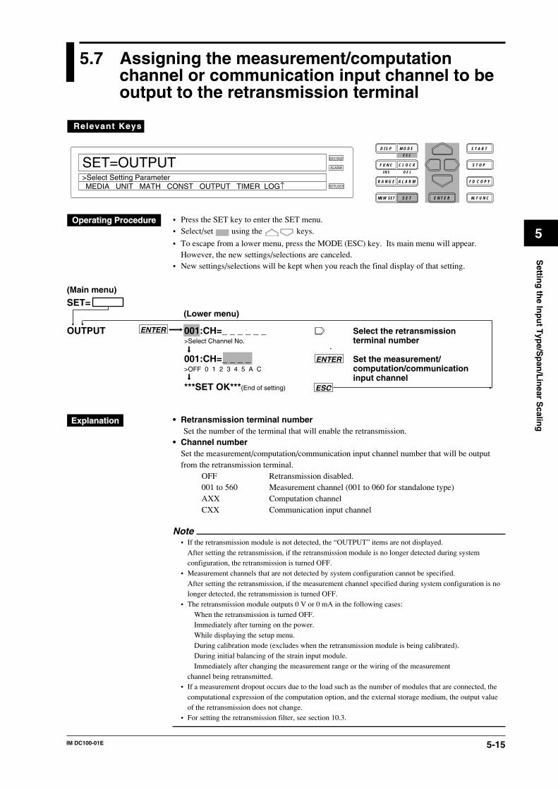
5-15IM DC100-01E
5
Settin
g th
e Inp
ut T
ype/S
pan
/Lin
ear Scalin
g
5.7 Assigning the measurement/computationchannel or communication input channel to beoutput to the retransmission terminal
RECORD
ALARM
KEYLOCK
SET=OUTPUT
MEDIA UNIT MATH CONST OUTPUT TIMER LOG↑
Relevant Keys
>Select Setting Parameter
D I S P M O D E
C L O C KF U N C
I N S D E L
R A N G E A L A R M
S E TMEM SET E N T E R
S T O P
F D C O P Y
M. F U N C
S T A R TE S C
• Press the SET key to enter the SET menu.• Select/set using the keys.
• To escape from a lower menu, press the MODE (ESC) key. Its main menu will appear.However, the new settings/selections are canceled.
• New settings/selections will be kept when you reach the final display of that setting.
SET=
OUTPUT ENTER
ENTER
ESC
(Main menu)
001:CH=_ _ _ _ _ _ Select the retransmission>Select Channel No. terminal number
001:CH=_ _ _ _ Set the measurement/>OFF 0 1 2 3 4 5 A C computation/communication
input channel***SET OK***(End of setting)
(Lower menu)
• Retransmission terminal numberSet the number of the terminal that will enable the retransmission.
• Channel numberSet the measurement/computation/communication input channel number that will be outputfrom the retransmission terminal.
OFF Retransmission disabled.001 to 560 Measurement channel (001 to 060 for standalone type)AXX Computation channelCXX Communication input channel
Note• If the retransmission module is not detected, the “OUTPUT” items are not displayed.
After setting the retransmission, if the retransmission module is no longer detected during systemconfiguration, the retransmission is turned OFF.
• Measurement channels that are not detected by system configuration cannot be specified.After setting the retransmission, if the measurement channel specified during system configuration is nolonger detected, the retransmission is turned OFF.
• The retransmission module outputs 0 V or 0 mA in the following cases:When the retransmission is turned OFF.Immediately after turning on the power.While displaying the setup menu.During calibration mode (excludes when the retransmission module is being calibrated).During initial balancing of the strain input module.Immediately after changing the measurement range or the wiring of the measurement
channel being retransmitted.• If a measurement dropout occurs due to the load such as the number of modules that are connected, the
computational expression of the computation option, and the external storage medium, the output valueof the retransmission does not change.
• For setting the retransmission filter, see section 10.3.
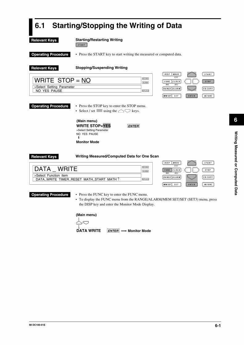
6-1IM DC100-01E
6
Writin
g M
easured
or C
om
pu
ted D
ata
6.1 Starting/Stopping the Writing of Data
Starting/Restarting WritingS T A R T
• Press the START key to start writing the measured or computed data.
Stopping/Suspending Writing
D I S P M O D E
C L O C KF U N C
I N S D E L
R A N G E A L A R M
S E TMEM SET E N T E R
S T O P
F D C O P Y
M. F U N C
RECORD
ALARM
KEYLOCK
S T A R T
WRITE STOP = NO
NO YES PAUSE>Select Setting Parameter
E S C
• Press the STOP key to enter the STOP menu.• Select / set using the keys.
Monitor Mode
WRITE STOP=YES>Select Setting ParameterNO YES PAUSE
ENTER
(Main menu)
Writing Measured/Computed Data for One Scan
D I S P M O D E
C L O C KF U N C
I N S D E L
R A N G E A L A R M
S E TMEM SET E N T E R
S T O P
F D C O P Y
M. F U N C
RECORD
ALARM
KEYLOCK
S T A R T
DATA _ WRITE
DATA_WRITE TIMER_RESET MATH_START MATH ↑>Select Function item
E S C
• Press the FUNC key to enter the FUNC menu.• To display the FUNC menu from the RANGE/ALARM/MEM SET/SET (SET3) menu, press
the DISP key and enter the Monitor Mode Display.
DATA WRITE
(Main menu)
Monitor ModeENTER
6-2 IM DC100-01E
Starting writing (WRITE START)In case of the measured/computed data, if WRITE TRIG is FREE, this opens a file and startswriting. If writing has been suspended, it restarts writing. If WRITE TRIG is set to TRIG, it isready for a trigger.• When writing measured/computed data and periodic file or writing measured/computed data
and report file on the DC100 with the report option, the two files are written simultaneously.• When measured/computed data, report data or periodic file writing is started, the word
RECORD indicating the status in the display is lit.• For the writing operation, see Section 6.2, “Setting a Writing Channel or Writing Operation.”• Writing can also be started using the event/action function. For an example of an event/action
setting, see Section 6.3, “Starting the Writing Using Event or Action Functions” (page 6-9).
Stopping/Suspending Writing (WRITE STOP)• Select whether to stop/suspend writing or not.
• YES: This closes a file and stops writing.• PAUSE: This suspends writing. The file remains open.• NO: This does not stop/suspend writing.
• By selecting YES and pressing the ENTER key, writing is stopped. The word RECORDindicating the status in the display goes off.
• By selecting PAUSE and pressing the ENTER key, writing is suspended. The word RECORDindicating the status in the display remains lit.
• Writing can also be suspended/restarted using the event/action function. If PAUSE is set as alevel action for alarm, relay, or remote events using the event/action function, suspension/restarting through a key operation cannot be done.
• “PAUSE” is available for the measured/computed data and the peridic file.
Writing Data for One Scan• A measured data item for one scan (one per channel) retained when the ENTER key is pressed
is written in the measured/computed file.• This operates separately from the writing period.• This can also be executed using the event/action function.• This function is available for the measured/computed data.
Display During Data WritingOne of the following statuses is displayed in sub-display 2 (the lowest line of the display part).
1 : Writing measured/computed data files only.
2 : Writing periodic file or report file only.
A : Writing measured/computed data file and periodic file or measured/computed data file
and report file.
P : Writing paused
B : Binary copying
Restriction During Data WritingThe following settings cannot be made during data writing:• All media source settings except for stopping/suspending writing.• Saving/reading set data• Measuring range• Computation expression/constants• Group• Inter-channel copying• Media source settings as actions for the event/action function
6.1 Starting/Stopping the Writing of Data
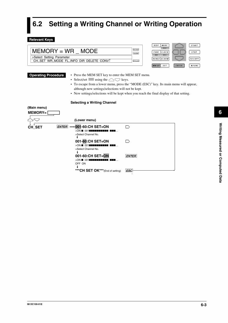
6-3IM DC100-01E
6
Writin
g M
easured
or C
om
pu
ted D
ata
6.2 Setting a Writing Channel or Writing Operation
D I S P M O D E
C L O C KF U N C
I N S D E L
R A N G E A L A R M
S E TMEM SET E N T E R
S T O P
F D C O P Y
M. F U N C
RECORD
ALARM
KEYLOCK
S T A R T
MEMORY = WR _ MODE
CH_SET WR_MODE FL_INFO DIR DELETE CONV↑>Select Setting Parameter
E S C
• Press the MEM SET key to enter the MEM SET menu.• Select/set using the keys.• To escape from a lower menu, press the “MODE (ESC)” key. Its main menu will appear,
although new settings/selections will not be kept.• New settings/selections will be kept when you reach the final display of that setting.
Selecting a Writing Channel
001-60:CH SET=ON>ON 001 …>Select Channel No.
001-60:CH SET=ON>ON 001 …>Select Channel No.
001-60:CH SET=ON>ON 001 …OFF ON
***CH SET OK***(End of setting)
MEMORY=
CH_SET
ESC
(Main menu)
(Lower menu)
ENTER
ENTER
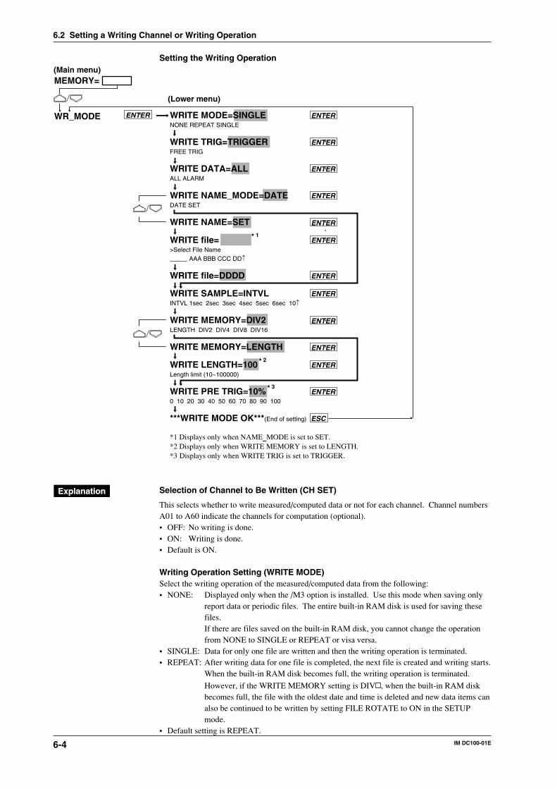
6-4 IM DC100-01E
Setting the Writing Operation
WRITE MODE=SINGLENONE REPEAT SINGLE
WRITE TRIG=TRIGGERFREE TRIG
WRITE DATA=ALLALL ALARM
WRITE NAME_MODE=DATEDATE SET
WRITE NAME=SET
WRITE file=>Select File Name______ AAA BBB CCC DD↑
WRITE file=DDDD
WRITE SAMPLE=INTVLINTVL 1sec 2sec 3sec 4sec 5sec 6sec 10↑
WRITE MEMORY=DIV2LENGTH DIV2 DIV4 DIV8 DIV16
WRITE MEMORY=LENGTH
WRITE LENGTH=100Length limit (10~100000)
WRITE PRE TRIG=10%0 10 20 30 40 50 60 70 80 90 100
***WRITE MODE OK***(End of setting)
*1 Displays only when NAME_MODE is set to SET.*2 Displays only when WRITE MEMORY is set to LENGTH.*3 Displays only when WRITE TRIG is set to TRIGGER.
MEMORY=
WR_MODE
ESC
(Main menu)
(Lower menu)
ENTER
ENTER
ENTER
ENTER
ENTER
ENTER
ENTER
ENTER
ENTER
ENTER
ENTER
ENTER
ENTER
* 1
* 2
* 3
Selection of Channel to Be Written (CH SET)
This selects whether to write measured/computed data or not for each channel. Channel numbersA01 to A60 indicate the channels for computation (optional).• OFF: No writing is done.• ON: Writing is done.• Default is ON.
Writing Operation Setting (WRITE MODE)Select the writing operation of the measured/computed data from the following:• NONE: Displayed only when the /M3 option is installed. Use this mode when saving only
report data or periodic files. The entire built-in RAM disk is used for saving thesefiles.If there are files saved on the built-in RAM disk, you cannot change the operationfrom NONE to SINGLE or REPEAT or visa versa.
• SINGLE: Data for only one file are written and then the writing operation is terminated.• REPEAT: After writing data for one file is completed, the next file is created and writing starts.
When the built-in RAM disk becomes full, the writing operation is terminated.
However, if the WRITE MEMORY setting is DIV , when the built-in RAM diskbecomes full, the file with the oldest date and time is deleted and new data items canalso be continued to be written by setting FILE ROTATE to ON in the SETUPmode.
• Default setting is REPEAT.
6.2 Setting a Writing Channel or Writing Operation
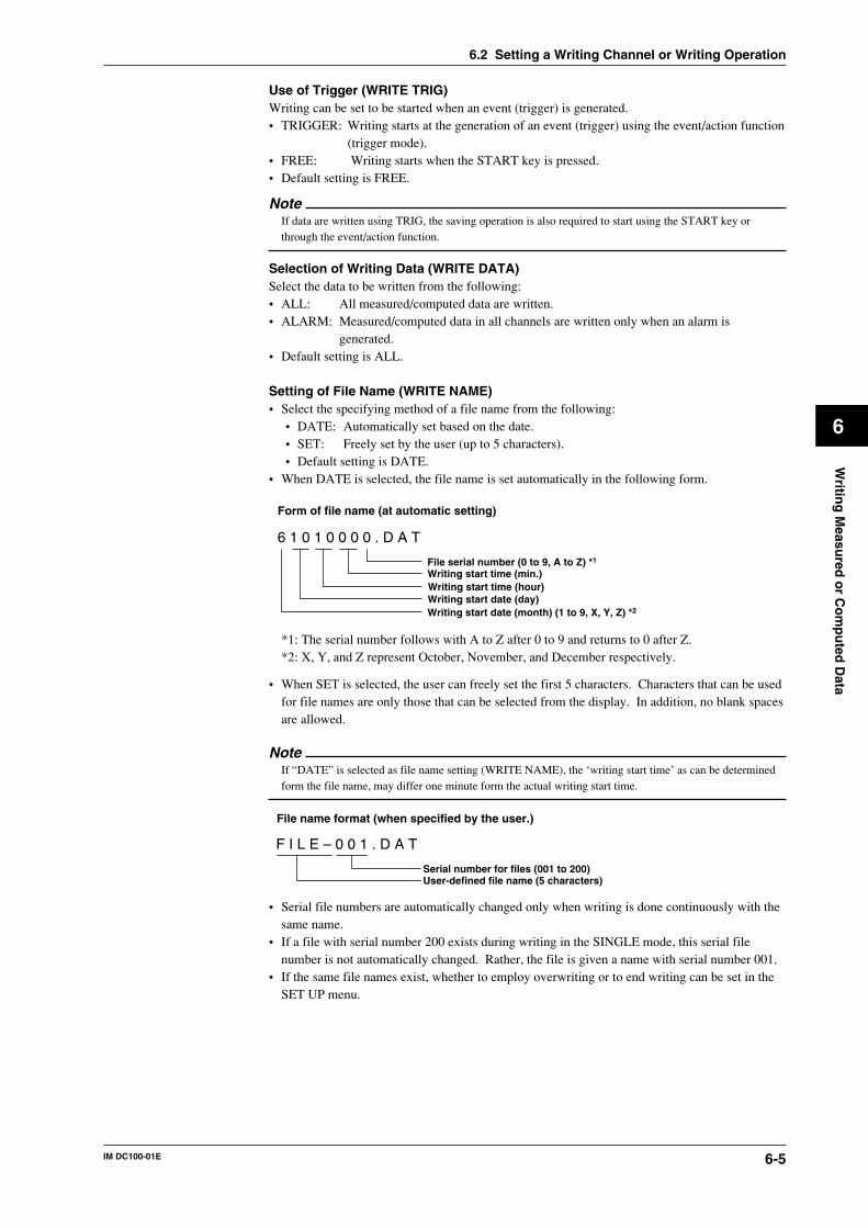
6-5IM DC100-01E
6
Writin
g M
easured
or C
om
pu
ted D
ata
Use of Trigger (WRITE TRIG)Writing can be set to be started when an event (trigger) is generated.• TRIGGER: Writing starts at the generation of an event (trigger) using the event/action function
(trigger mode).• FREE: Writing starts when the START key is pressed.• Default setting is FREE.
NoteIf data are written using TRIG, the saving operation is also required to start using the START key orthrough the event/action function.
Selection of Writing Data (WRITE DATA)Select the data to be written from the following:• ALL: All measured/computed data are written.• ALARM: Measured/computed data in all channels are written only when an alarm is
generated.• Default setting is ALL.
Setting of File Name (WRITE NAME)• Select the specifying method of a file name from the following:
• DATE: Automatically set based on the date.• SET: Freely set by the user (up to 5 characters).• Default setting is DATE.
• When DATE is selected, the file name is set automatically in the following form.
6 1 0 1 0 0 0 0 . D A T AUT
File serial number (0 to 9, A to Z) *1
Writing start time (min.) Writing start time (hour) Writing start date (day) Writing start date (month) (1 to 9, X, Y, Z) *2
Form of file name (at automatic setting)
*1: The serial number follows with A to Z after 0 to 9 and returns to 0 after Z.*2: X, Y, and Z represent October, November, and December respectively.
• When SET is selected, the user can freely set the first 5 characters. Characters that can be usedfor file names are only those that can be selected from the display. In addition, no blank spacesare allowed.
NoteIf “DATE” is selected as file name setting (WRITE NAME), the ‘writing start time’ as can be determinedform the file name, may differ one minute form the actual writing start time.
F I L E – 0 0 1 . D A T AUT
Serial number for files (001 to 200)User-defined file name (5 characters)
File name format (when specified by the user.)
• Serial file numbers are automatically changed only when writing is done continuously with thesame name.
• If a file with serial number 200 exists during writing in the SINGLE mode, this serial filenumber is not automatically changed. Rather, the file is given a name with serial number 001.
• If the same file names exist, whether to employ overwriting or to end writing can be set in theSET UP menu.
6.2 Setting a Writing Channel or Writing Operation
6-6 IM DC100-01E
Writing Period• The period in which data are written can be selected from the following:
• INTVL: The same as the measuring period. Measured/computed data are saved withoutthinning-out.
• 1 sec, 2 sec, 3 sec, 4 sec, 5 sec, 6 sec, 10 sec, 12 sec, 15 sec, 20 sec, 30 sec, 1 min, 2 min, 3min, 4 min, 5 min, 10 min, 30 min, or 60 min: Writing is done with the set period.
However, only those values which are multiples of the measuring period can beselected.
• LOGIC: Only effective if event/action is set to action “DATA_WR.” Every time an eventis generated, the data item for one scan (one for each channel) is written. For theevent/action, see Section 9.1, “Setting Event/Action Functions” (page 9-1).
• Default setting is INTVL.• If the computation channel is used, missing computation measurements may occur depending
on the number of computation expressions or measuring period. If the computationmeasurement missing status is displayed, make the measuring period longer or decrease thecomputation expressions.
• When the measuring period is changed, the writing period will not equal the measuring periodor its integral multiples, and is subsequently adjusted to equate with the measuring period.
Built-in RAM Disk Usage (WRITE MEMORY)• Select the built-in RAM disk usage from the following:
• LENGTH: Determine the file capacity by specifying the number of data items per channel.• DIV2, DIV4, DIV8, or DIV16: Use the RAM disk by dividing the disk area into 2, 4, 8 or
16 parts. If the memory capacity is 4 MB, 2 cannot be used.• If a file is saved in the built-in RAM disk, the usage of the built-in RAM disk cannot be
changed. For this purpose, initialize the RAM disk or change the setting after deleting all thefiles. In that case, necessary files must be saved on a floppy disk.
Writing Data Length (WRITE LENGTH)• If WRITE MEMORY is set to LENGTH, set the number of data items to be written per
channel.• However, a data length exceeding a file size of 1 MB cannot be selected depending on the
number of channels.• After starting writing, even if the writing is stopped before the specified data length is reached,
the file capacity is taken by the area for the specified data length.
Note• When using the computation channel, do not write measured/computed data in an application where the
measurement interval is shorter than 0.5 sec, the writing interval is set to INTVL, or the data length isshorter than 50, if:• the writing action is in the REPEAT mode.
• Doing so may result in incorrect writing.• When the Writing operation is set to REPEAT and there is not enough space to create a new file on the
internal RAM disk, the files are deleted in order form the oldest file to create the new file. If thenecessary space to create the new file cannot be allocated after deleting the five oldest files, the writingoperation stops.
• If there are a lot of files on the internal RAM disk, file switching takes time. In some cases, this causesdrop outs in the writing operation. In this case, delete unnecessary files form the RAM disk or increasethe measurement interval.
Pretrigger (WRITE PRETRIG)• If WRITE TRIG is set to TRIGGER, the data before the trigger (event) generation can be saved
in part of the set file. Setting is done as a percentage of the file capacity in 10% increments.
Trigger (event)
20%
File capacity (100%)
Data before the trigger generation
• If a pretrigger is used (except 0%), it is necessary to set the writing start trigger (WR_TRIG) tothe action in the event/action function.
6.2 Setting a Writing Channel or Writing Operation

6-7IM DC100-01E
6
Writin
g M
easured
or C
om
pu
ted D
ata
Data FormatThe measured/computed data are saved in the binary format.
Data CapacityThe data capacity is determined by the following formula.
Measured data: 2 bytes/data itemComputed data: 4 bytes/data itemFor stand-alone model:
Header 256 + 64 × (number of measuring channels + number of computing channels) bytesData capacity = 256 + 64 × (number of measuring channels + number of computing
channels) + (number of measuring channels × 2 + number of computingchannels × 4 + 6) × data length
For expandable model:Header 576 + 64 × (number of measuring channels + number of computing channels) bytesData capacity = 576 + 64 × (number of measuring channels + number of computing
channels) + (number of measuring channels × 2 + number of computingchannels × 4 + 6) × data length
For example, in the case of a stand-alone model, if the number of measuring channels = 10,number of computing channels = 5, data length = 5k, the data capacity is as follows:
Data capacity = 256 + 64 × (10 + 5) + (10 × 2 + 5 × 4 + 6) × 5k = 231216 bytesSince the data is saved to the built-in RAM disk in units of 1024 bytes, the actual capacity usedis 231424 bytes.
Measuring Time for Each FileThe summary of the measuring time for each file is shown below.
1037312 bytes 2084864 bytes 4178944 bytes
7817 Data
2
15761 Data
2
15792 Data
4
518098 bytes 1042402 bytes 1044448 bytes
0.5 s2 s30 s60 min
1 hr 5 min 8 s4 hr 20 min 32 s65 hr 8 min 0s325 day 16 hr 0 min 0 s
2 hr 11 min 20 s8 hr 45 min 20 s5 day 11 hr 20 min 0 s656 day 16 hr 0 min 0 s
2 hr 11 min 36 s8 hr 46 min 22 s5 day 11 hr 35 min 30 s659 day 23 hr 0 min 0 s
1037312 bytes 2084864 bytes 4178944 bytes
822 Data 1687 Data 1630 Data
517908 bytes 1042098 bytes 1043916 bytes
0.5 s2 s30 s60 min
6 min 51 s27 min 22 s6 hr 50 min 30 s34 day 5 hr 0 min 0 s
14 min 3 s56 min 12 s14 hr 3 min 0 s70 day 6 hr 0 min 0 s
14 min 5 s56 min 18 s14 hr 4 min 30 s70 day 9 hr 0 min 0 s
Stand-alone Type Number of measuring CH: 30 Computing CH: OFF
Built-in RAM disk capacity
Built-in RAM disk capacity
Data length
Number of partitions on the built-in RAM disk
2 2 4Number of partitions on the built-in RAM disk
Data length
File size
File size
Mea
suri
ng
ti
me
Measuring period
Measuring period
File size = 256 + 64 × number of measuring channels + (2 × number of measuring channels + 6) × data length
File size = 576 + 64 × number of measuring channels + (2 × number of measuring channels + 6) × data length
Extended Type Number of measuring CH: 300 Computing CH: OFF
Mea
suri
ng
ti
me
6.2 Setting a Writing Channel or Writing Operation
6-8 IM DC100-01E
Example of setting when measured data are saved continuouslyMeasured data are continuously saved.Operation flow:1. Set file cancellation to be executed when copying files in the SET UP menu.
(Power ON + DISP key) enters the SET UP menu.“MEM SET” in SET UP menu FILE COPY & DELETE = ONTerminate SET UP menu. END = STORE
2. Set to execute copying when the file is ended in the event/action setting.“LOGIC” in SET menu LOGIC BOX No.
EVENT = FILE_ENDACT = EDGE/MEMRY:CP_FDD
3. Set the writing operation.“WRITE MODE” in MEM SET menu WRITE MODE = REPEAT
WRITE TRIG = FREEWRITE DATA = ALLWRITE NAME = DATEWRITE MEMORY = DIV2
4. Start by pressing the START key.
• Either step 2 or step 3 of the setting operation can follow step 1.
Operation flow:
Internal RAM Disk
(1/2) (1/2)
FDD
Delete
FDD
• After one side file has been created, another side file is created to continue writing. At the same time, the first file is copied to a floppy disk.
• The first file is cancelled at the same time as the copy is completed.
• After the second file has been created, a third file is started to be created in the area where the first file was cancelled. At the same time, the second file is copied onto the floppy disk.
6.2 Setting a Writing Channel or Writing Operation
6-9IM DC100-01E
6
Writin
g M
easured
or C
om
pu
ted D
ata
6.3 Starting Writing Using Event or ActionFunctions
Flow of operationA flow of the operation will be shown taking the case where measured/computed data areautomatically saved every time an alarm is generated.
1. Select the writing channel.
Menu Item Setting
“CH SET” in MEM SET menu 001-01: CH SET=ON(Allowed to set the consecutive numbers of channels)
2. Set the writing operation.In this case, set the writing so that data before an alarm generation are acquired within 30 % ofthe file capacity.
Menu Item Setting
“WRITE MODE” in MEM SET menu WRITE MODE=REPEATWRITE TRIG=TRIGGERWRITE DATA=ALLWRITE NAME=DATEWRITE MEMORY=LENGTHWRITE LENGTH=1 kWRITE PRE TRIG=30 %
3. Set an event/action.
Menu Item Setting
“LOGIC” in SET menu LOGIC BOX No.EVENT=ALARMACT=EDGE/MEMORY : WR_TRIG
4. Obtain the status ready for trigger by pressing the START key.Subsequently, the operation to write measured/computed data at every alarm generation can berepeated for the number of files in the RAM disk.
See Section 6.2 for the settings of 1 and 2, and see the next page for the setting of 3. Also, seeSection 6.1 for the operation of 4.
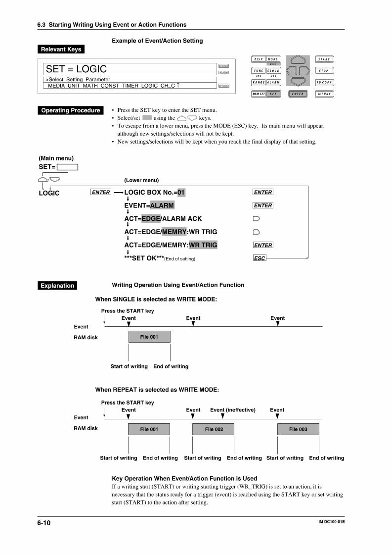
6-10 IM DC100-01E
Example of Event/Action Setting
D I S P M O D E
C L O C KF U N C
I N S D E L
R A N G E A L A R M
S E TMEM SET E N T E R
S T O P
F D C O P Y
M. F U N C
RECORD
ALARM
KEYLOCK
S T A R T
SET = LOGIC
MEDIA UNIT MATH CONST TIMER LOGIC CH_C ↑>Select Setting Parameter
E S C
• Press the SET key to enter the SET menu.• Select/set using the keys.• To escape from a lower menu, press the MODE (ESC) key. Its main menu will appear,
although new settings/selections will not be kept.• New settings/selections will be kept when you reach the final display of that setting.
LOGIC BOX No.=01
EVENT=ALARM
ACT=EDGE/ALARM ACK
ACT=EDGE/MEMRY:WR TRIG
ACT=EDGE/MEMRY:WR TRIG
***SET OK***(End of setting)
(Lower menu)
SET=
LOGIC
ESC
(Main menu)
ENTER ENTER
ENTER
ENTER
Writing Operation Using Event/Action Function
Event Event Event
Start of writing End of writing
Start of writing End of writing Start of writing End of writing Start of writing End of writing
File 001
File 001 File 002 File 003
Event
RAM disk
Event
RAM disk
Press the START key
Event Event Event (ineffective) EventPress the START key
When SINGLE is selected as WRITE MODE:
When REPEAT is selected as WRITE MODE:
Key Operation When Event/Action Function is UsedIf a writing start (START) or writing starting trigger (WR_TRIG) is set to an action, it isnecessary that the status ready for a trigger (event) is reached using the START key or set writingstart (START) to the action after setting.
6.3 Starting Writing Using Event or Action Functions
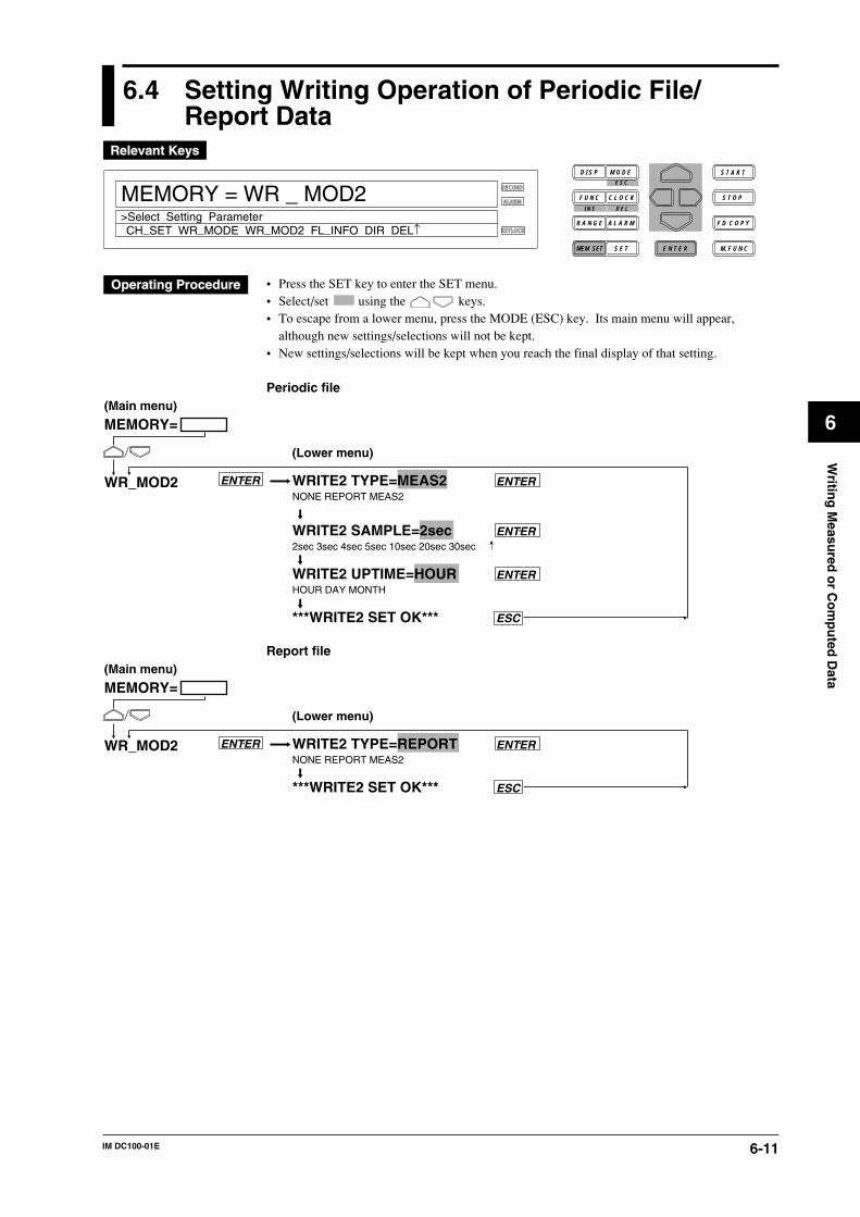
6-11IM DC100-01E
6
Writin
g M
easured
or C
om
pu
ted D
ata
6.4 Setting Writing Operation of Periodic File/Report Data
D I S P M O D E
C L O C KF U N C
I N S D E L
R A N G E A L A R M
S E TMEM SET E N T E R
S T O P
F D C O P Y
M. F U N C
RECORD
ALARM
KEYLOCK
S T A R T
MEMORY = WR _ MOD2
CH_SET WR_MODE WR_MOD2 FL_INFO DIR DEL↑>Select Setting Parameter
E S C
• Press the SET key to enter the SET menu.• Select/set using the keys.• To escape from a lower menu, press the MODE (ESC) key. Its main menu will appear,
although new settings/selections will not be kept.• New settings/selections will be kept when you reach the final display of that setting.
Periodic file
WRITE2 TYPE=MEAS2 ENTER NONE REPORT MEAS2
WRITE2 SAMPLE=2sec ENTER2sec 3sec 4sec 5sec 10sec 20sec 30sec
WRITE2 UPTIME=HOUR ENTERHOUR DAY MONTH
***WRITE2 SET OK*** ESC
MEMORY=
WR_MOD2
(Main menu)
(Lower menu)
ENTER
Report file
WRITE2 TYPE=REPORT ENTER NONE REPORT MEAS2
***WRITE2 SET OK*** ESC
MEMORY=
WR_MOD2
(Main menu)
(Lower menu)
ENTER
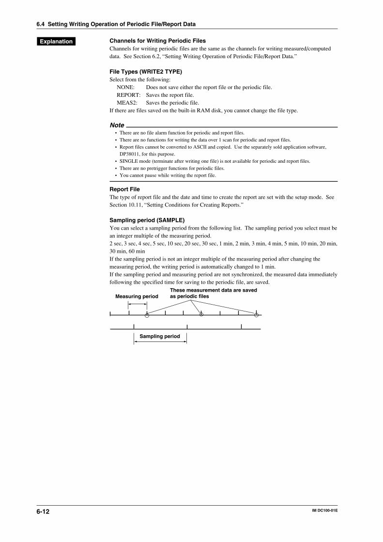
6-12 IM DC100-01E
Channels for Writing Periodic FilesChannels for writing periodic files are the same as the channels for writing measured/computeddata. See Section 6.2, “Setting Writing Operation of Periodic File/Report Data.”
File Types (WRITE2 TYPE)Select from the following:
NONE: Does not save either the report file or the periodic file.REPORT: Saves the report file.MEAS2: Saves the periodic file.
If there are files saved on the built-in RAM disk, you cannot change the file type.
Note• There are no file alarm function for periodic and report files.• There are no functions for writing the data over 1 scan for periodic and report files.• Report files cannot be converted to ASCII and copied. Use the separately sold application software,
DP38011, for this purpose.• SINGLE mode (terminate after writing one file) is not available for periodic and report files.• There are no pretrigger functions for periodic files.• You cannot pause while writing the report file.
Report FileThe type of report file and the date and time to create the report are set with the setup mode. SeeSection 10.11, “Setting Conditions for Creating Reports.”
Sampling period (SAMPLE)You can select a sampling period from the following list. The sampling period you select must bean integer multiple of the measuring period.2 sec, 3 sec, 4 sec, 5 sec, 10 sec, 20 sec, 30 sec, 1 min, 2 min, 3 min, 4 min, 5 min, 10 min, 20 min,30 min, 60 minIf the sampling period is not an integer multiple of the measuring period after changing themeasuring period, the writing period is automatically changed to 1 min.If the sampling period and measuring period are not synchronized, the measured data immediatelyfollowing the specified time for saving to the periodic file, are saved.
Measuring periodThese measurement data are saved as periodic files
Sampling period
6.4 Setting Writing Operation of Periodic File/Report Data
6-13IM DC100-01E
6
Writin
g M
easured
or C
om
pu
ted D
ata
6.4 Setting Writing Operation of Periodic File/Report Data
Up Time (UP TIME)Sets the time for creating the files.
HOUR: Create files on the hour (measured data over an hour).DAY: Create files at the specified time every day (measured data over a day).
The time of creation is the same as the time for creating daily report.MONTH: Create files at the specified time every month (measured data over a month).
The date and time of creation is the same as the date and time for creatingmonthly report.
For the setting procedure, see section 10.12, “Setting Conditions for Creating Reports.”
Conditions to Start Writing DataPressing the START key starts the writing.• If the measured/computed data are to be written, writing also starts for these data.• For a report file, writing does not start unless the report operation is in the start condition. Start
the report operation at the screen that appears when the “FUNC” key is pressed or by setting“REPORT START” in the action of the event/action function.
• You can also start writing with the event/action function. For details, see section 9.1 “SettingEvent/Action Functions.”
Note• Writing of periodic file sometimes fails, if the start, stop and restart operations of the periodic file are all
executed within one minute. Execute these operations so that each operation do not fall within the sameminute.
• Since the first periodic or report file saves the data from the time the writing started to the first date andtime for creating the periodic/report file, the data length may be shorter than the designated length.
CopyPeriodic files can be converted to ASCII format when copying the data from the built-in RAMdisk to the floppy disk or MO/ZIP/PD disk.
Writing MethodPeriodic files and report files are created until the built-in RAM disk becomes full. You can alsohave the old files be overwritten with new files with the SET UP mode setting. For report files,the oldest file is deleted.If deleting the oldest file does not free enough space for the new file, the next oldest file isdeleted. If deleting the five oldest files does not free enough space for the new file, the writing isaborted.
NoteFor periodic files, sometimes new files cannot be written after changing the conditions for writing theperiodic files when old files are present in the built-in RAM disk. In this case, copy the remaining periodicfiles to the disk and delete them from the RAM disk.
File NamePeriodic fileThe file names of periodic files are set automatically as follows.MddhhmmZ.DAS
M: Month (1 to 9, X, Y, and Z. X, Y, and Z stand for October, November, and December,respectively.)
dd: day (1 to 31)hh: hour (0 to 23)mm: minute (0 to 59)Z: Fixed to Z.
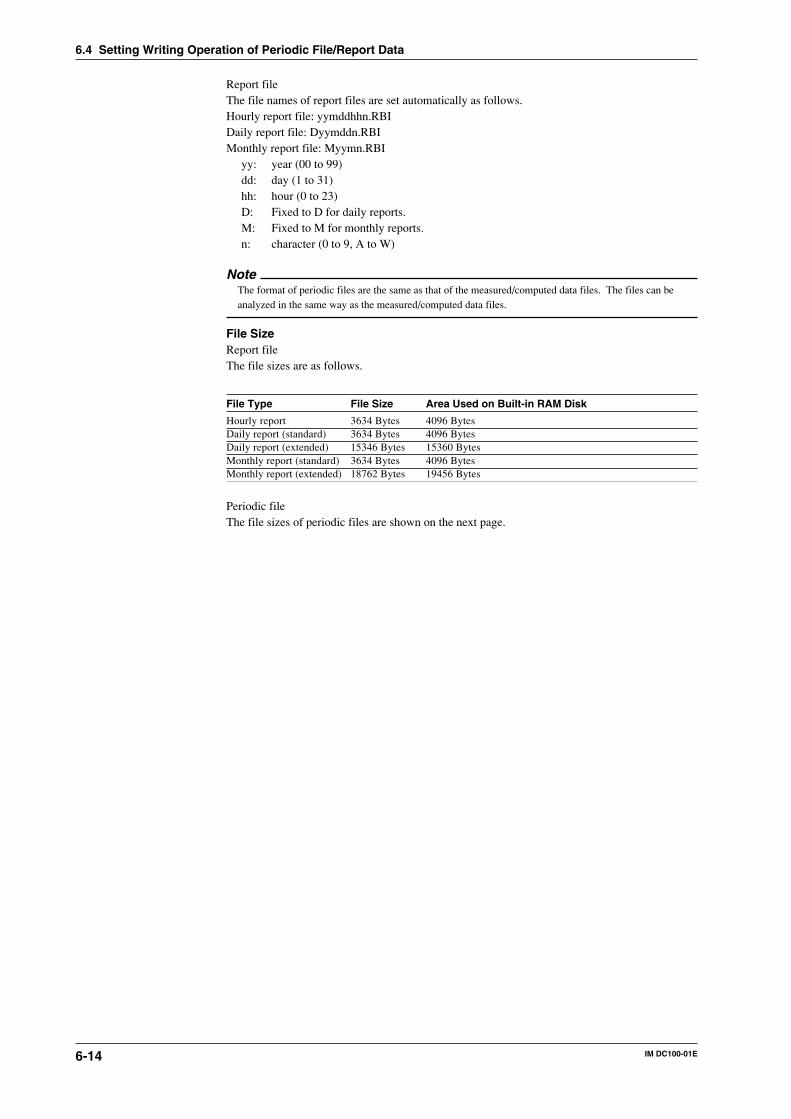
6-14 IM DC100-01E
6.4 Setting Writing Operation of Periodic File/Report Data
Report fileThe file names of report files are set automatically as follows.Hourly report file: yymddhhn.RBIDaily report file: Dyymddn.RBIMonthly report file: Myymn.RBI
yy: year (00 to 99)dd: day (1 to 31)hh: hour (0 to 23)D: Fixed to D for daily reports.M: Fixed to M for monthly reports.n: character (0 to 9, A to W)
NoteThe format of periodic files are the same as that of the measured/computed data files. The files can beanalyzed in the same way as the measured/computed data files.
File SizeReport fileThe file sizes are as follows.
File Type File Size Area Used on Built-in RAM Disk
Hourly report 3634 Bytes 4096 BytesDaily report (standard) 3634 Bytes 4096 BytesDaily report (extended) 15346 Bytes 15360 BytesMonthly report (standard) 3634 Bytes 4096 BytesMonthly report (extended) 18762 Bytes 19456 Bytes
Periodic fileThe file sizes of periodic files are shown on the next page.
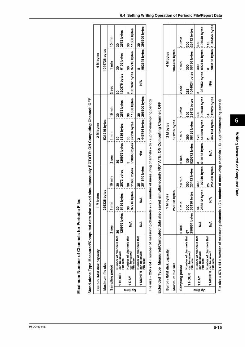
6-15IM DC100-01E
6
Writin
g M
easured
or C
om
pu
ted D
ata
6.4 Setting Writing Operation of Periodic File/Report Data
1 M
byt
es2
M b
ytes
4 M
byt
es
2593
28 b
ytes
5212
16 b
ytes
1044
736
byt
es
2 se
c
67 2568
64 b
ytes
1 m
in10
min
300
5613
6 b
ytes
300
2341
2 b
ytes
300
1070
40 b
ytes
25 2512
60 b
ytes
84 2565
12 b
ytes
2 se
c
139
5206
72 b
ytes
1 m
in10
min
300
5613
6 b
ytes
300
2341
2 b
ytes
300
1070
40 b
ytes
54 5129
28 b
ytes
173
5185
28 b
ytes
3 5191
68 b
ytes
2 4471
04 b
ytes
282
1044
624
byt
es30
056
136
byt
es30
023
412
byt
es
300
1070
40 b
ytes
113
1043
456
byt
es
300
8924
16 b
ytes
9 1037
952
byt
es
8 9831
68 b
ytes
2 se
c1
min
10 m
in
1 M
byt
es2
M b
ytes
4 M
byt
es
2593
28 b
ytes
5212
16 b
ytes
1044
736
byt
es
2 se
c
30 1209
76 b
ytes
1 m
in10
min
30 6136
byt
es30 25
72 b
ytes
30 1168
0 b
ytes
25 2518
40 b
ytes
30 9721
6 b
ytes
2 se
c1
min
10 m
in
30 2968
00 b
ytes
3 5188
48 b
ytes
2 4467
84 b
ytes
9 1037
632
byt
es
8 9828
48 b
ytes
2 se
c1
min
10 m
in
30 1209
76 b
ytes
30 6136
byt
es30 25
72 b
ytes
30 1168
0 b
ytes
30 9721
6 b
ytes
30 1209
76 b
ytes
30 6136
byt
es30 25
72 b
ytes
30 1168
0 b
ytes
30 9721
6 b
ytes
30 2968
00 b
ytes
1 H
OU
R
1 D
AY
1 M
ON
TH
1 H
OU
R
1 D
AY
1 M
ON
TH
Max
imu
m N
um
ber
of
Ch
ann
els
for
Per
iod
ic F
iles
Sta
nd
-alo
ne
Typ
e M
easu
red
/Co
mp
ute
d d
ata
also
sav
ed s
imu
ltan
eou
sly
RO
TA
TE
: O
N C
om
pu
tin
g C
han
nel
: O
FF
Bu
ilt-i
n R
AM
dis
k ca
pac
ity
Bu
ilt-i
n R
AM
dis
k ca
pac
ity
Max
imu
m f
ile s
ize
Max
imu
m f
ile s
ize
Sam
plin
g p
erio
d
Sam
plin
g p
erio
d
Up time Up time
Nu
mb
er o
f ch
ann
els
that
ca
n b
e sa
ved
F
ile s
ize
Nu
mb
er o
f ch
ann
els
that
ca
n b
e sa
ved
F
ile s
ize
Nu
mb
er o
f ch
ann
els
that
ca
n b
e sa
ved
F
ile s
ize
Nu
mb
er o
f ch
ann
els
that
ca
n b
e sa
ved
F
ile s
ize
Nu
mb
er o
f ch
ann
els
that
ca
n b
e sa
ved
F
ile s
ize
Nu
mb
er o
f ch
ann
els
that
ca
n b
e sa
ved
F
ile s
ize
N/A
N/A
N/A
N/A
N/A
N/A
N/A
N/A
N/A
N/A
File
siz
e =
256
+ 64
× n
um
ber
of
mea
suri
ng
ch
ann
els
+ (2
× n
um
ber
of
mea
suri
ng
ch
ann
els
+ 6)
× (
up
tim
e/sa
mp
ling
per
iod
)
File
siz
e =
576
+ 64
× n
um
ber
of
mea
suri
ng
ch
ann
els
+ (2
× n
um
ber
of
mea
suri
ng
ch
ann
els
+ 6)
× (
up
tim
e/sa
mp
ling
per
iod
)
Ext
end
ed T
ype
Mea
sure
d/C
om
pu
ted
dat
a al
so s
aved
sim
ult
aneo
usl
y R
OT
AT
E:
ON
Co
mp
uti
ng
Ch
ann
el:
OF
F
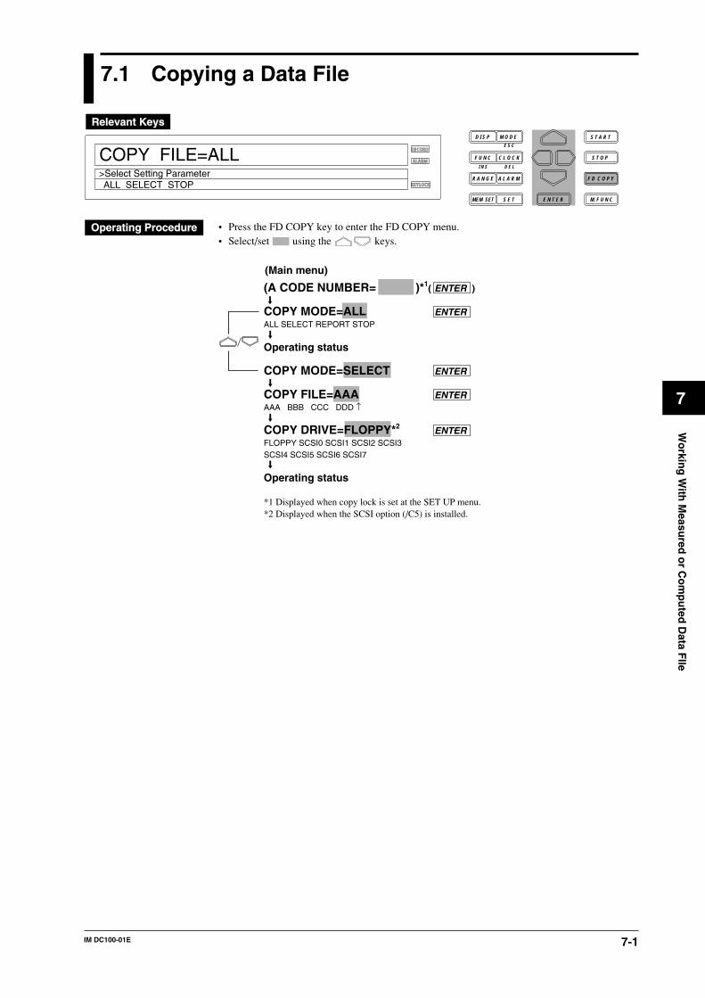
7-1IM DC100-01E
Wo
rking
With
Measu
red o
r Co
mp
uted
Data F
Ile
7
7.1 Copying a Data File
RECORD
ALARM
KEYLOCK
COPY FILE=ALL
ALL SELECT STOP>Select Setting Parameter
D I S P M O D E
C L O C KF U N C
I N S D E L
R A N G E A L A R M
S E TMEM SET E N T E R
S T O P
F D C O P Y
M. F U N C
S T A R TE S C
• Press the FD COPY key to enter the FD COPY menu.• Select/set using the keys.
(A CODE NUMBER= )*1( ENTER )
COPY MODE=ALL ENTERALL SELECT REPORT STOP
Operating status
COPY MODE=SELECT ENTER
COPY FILE=AAA ENTERAAA BBB CCC DDD ↑
COPY DRIVE=FLOPPY*2 ENTERFLOPPY SCSI0 SCSI1 SCSI2 SCSI3SCSI4 SCSI5 SCSI6 SCSI7
Operating status
*1 Displayed when copy lock is set at the SET UP menu.*2 Displayed when the SCSI option (/C5) is installed.
(Main menu)
7-2 IM DC100-01E
7.1 Copying a Data File
Copies measured/computed data, periodic files, and report files from the built-in RAM disk to thefloppy, MO/ZIP/PD disk. The extension for measured/computed data file is .DAT. Theextensions for periodic file and report file are .DAS and .RBI, respectively.
Copying to the Floppy, MO/ZIP/PD Disk• Select either to copy all the files or only the specified files.
ALL: Copies all files.If a file with the same file name already existon the floppy disk or the SCSIdevice, it is not copied.
SELECT: Copies one measured/computed data file or periodic file.If there is a file with the same name in the copying destination, overwriting isdone on the existing file.
REPORT: Copies one report file.If there is a file with the same name in the copying destination, overwriting isdone on the existing file.
• When copying, the file name cannot be changed.• If the floppy disk or SCSI device capacity is nearly reached while copying all files, “Change
Media *”appears in the main display. In such a case, copying can be continued by inserting anew floppy disk or SCSI device and pressing any key.
• If “Change Media *” is displayed while copying to the SCSI device, inserting a new SCSIdevice and pressing any key will copy the entire file to the new SCSI device. The old devicewill contain the file that was partially copied.
• Whether the file in the copying source is cancelled or not after copying can be set in the SETUP menu.
• By setting “FILE_END” to the event and “CP_FDD” or “CP_SCS0” to “CP_SCS7” to theaction using the event/action function, the file can automatically be saved on the floppy disk orSCSI device. In this case, all files are copied (except for report data).
Display During CopyingThe following status is displayed in sub-display 2 (the lowest display field).
B : File copying in process
Note• While copying is in process, set-up data cannot be saved or read.• Do not leave a floppy disk in the disk drive for a long period. Dust may get into the floppy disk drive
and cause it to fail.• When copying a file, do not set any item relating to floppy disks, MO, ZIP or PD such as the viewing of
directories. The file may not be copied correctly.
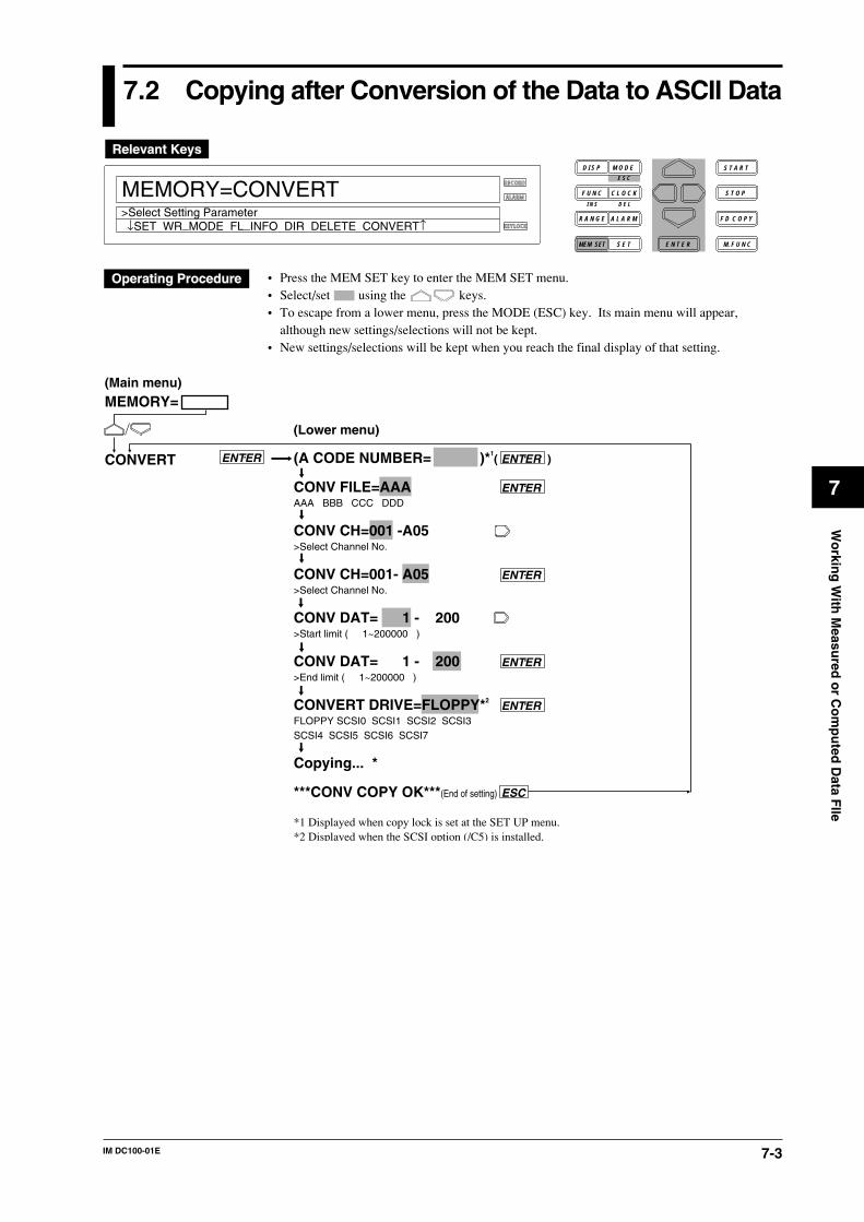
7-3IM DC100-01E
Wo
rking
With
Measu
red o
r Co
mp
uted
Data F
Ile
7
7.2 Copying after Conversion of the Data to ASCII Data
RECORD
ALARM
KEYLOCK
MEMORY=CONVERT
↓SET WR_MODE FL_INFO DIR DELETE CONVERT↑>Select Setting Parameter
D I S P M O D E
C L O C KF U N C
I N S D E L
R A N G E A L A R M
S E TMEM SET E N T E R
S T O P
F D C O P Y
M. F U N C
S T A R TE S C
• Press the MEM SET key to enter the MEM SET menu.• Select/set using the keys.• To escape from a lower menu, press the MODE (ESC) key. Its main menu will appear,
although new settings/selections will not be kept.• New settings/selections will be kept when you reach the final display of that setting.
(A CODE NUMBER= )*1( ENTER )
CONV FILE=AAA ENTER AAA BBB CCC DDD
CONV CH=001 -A05>Select Channel No.
CONV CH=001- A05 ENTER>Select Channel No.
CONV DAT= 1 - 200>Start limit ( 1~200000 )
CONV DAT= 1 - 200 ENTER>End limit ( 1~200000 )
CONVERT DRIVE=FLOPPY*2ENTER
FLOPPY SCSI0 SCSI1 SCSI2 SCSI3SCSI4 SCSI5 SCSI6 SCSI7
Copying... *
***CONV COPY OK***(End of setting) ESC
*1 Displayed when copy lock is set at the SET UP menu.*2 Displayed when the SCSI option (/C5) is installed.
MEMORY=
CONVERT
(Main menu)
(Lower menu)
ENTER
7-4 IM DC100-01E
7.2 Copying after Conversion of the Data to ASCII Data
Measured/computed data or periodic file in the internal RAM disk is converted to ASCII data,then copied to a floppy disk, MO, ZIP or PD. Report files cannot be converted to ASCII data andcopied. The identifier is .CSV.
Conversion channel (CONV CH)Used to select a channel whose data is to be converted to ASCII data. Measurement channels andcomputation channels are arranged in the order of 001, 002, ... 560, A01, A02, ... A60. Forinstance, if “559-A02” is specified, data for channels 559, 560, A01 and A02 will be converted.
Conversion data (CONV DATA)Used to specify the conversion range for the channels specified by CONV CH. Enter theconversion start data No. and end data No.
Copy Destination (CONV DRIVE)Displayed when the SCSI option (/C5) is installed. Select the copy destination from the built-infloppy disk of the DC100, external MO, ZIP or PD. For MO, ZIP and PD, select using the SCSIID.
Data capacityWhen measured/computed data is converted to ASCII data, 12 bytes will be used for each dataset. Thus, the data capacity can be calculated as follows.Data capacity = 178 + 20 x number of conversion channels - 2 + (24 + 12 x number of conversionchannels -1) x number of data sets to be convertedCopying is not possible if the destination’s disk capacity is insufficient.
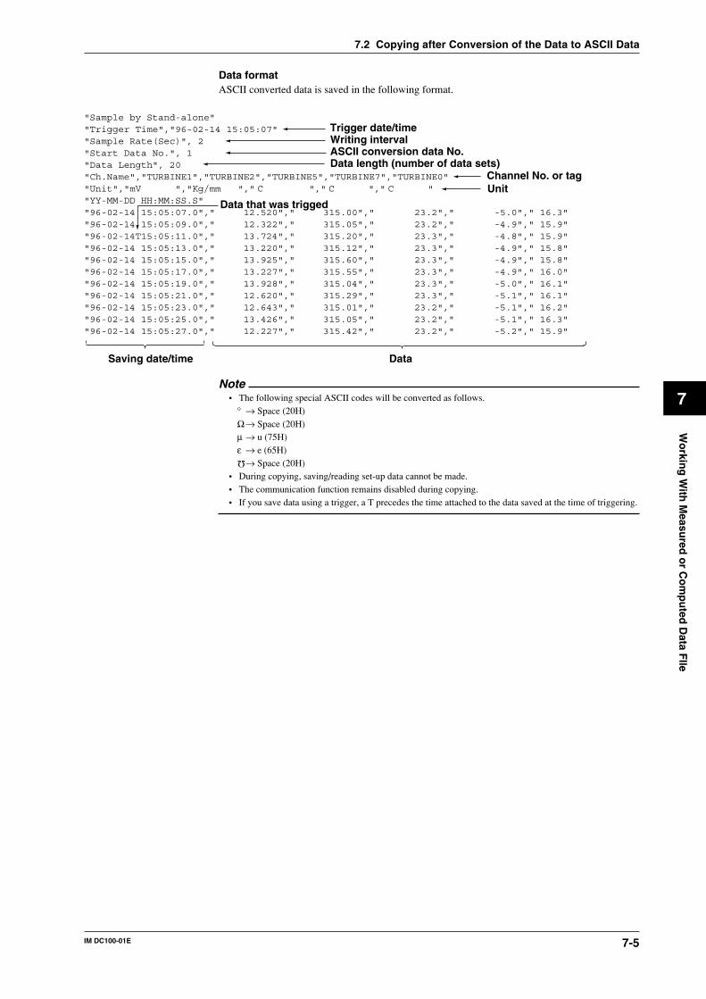
7-5IM DC100-01E
Wo
rking
With
Measu
red o
r Co
mp
uted
Data F
Ile
7
7.2 Copying after Conversion of the Data to ASCII Data
Data formatASCII converted data is saved in the following format.
"Sample by Stand-alone""Trigger Time","96-02-14 15:05:07""Sample Rate(Sec)", 2"Start Data No.", 1"Data Length", 20"Ch.Name","TURBINE1","TURBINE2","TURBINE5","TURBINE7","TURBINE0""Unit","mV ","Kg/mm "," C "," C "," C ""YY-MM-DD HH:MM:SS.S""96-02-14 15:05:07.0"," 12.520"," 315.00"," 23.2"," -5.0"," 16.3""96-02-14 15:05:09.0"," 12.322"," 315.05"," 23.2"," -4.9"," 15.9""96-02-14T15:05:11.0"," 13.724"," 315.20"," 23.3"," -4.8"," 15.9""96-02-14 15:05:13.0"," 13.220"," 315.12"," 23.3"," -4.9"," 15.8""96-02-14 15:05:15.0"," 13.925"," 315.60"," 23.3"," -4.9"," 15.8""96-02-14 15:05:17.0"," 13.227"," 315.55"," 23.3"," -4.9"," 16.0""96-02-14 15:05:19.0"," 13.928"," 315.04"," 23.3"," -5.0"," 16.1""96-02-14 15:05:21.0"," 12.620"," 315.29"," 23.3"," -5.1"," 16.1""96-02-14 15:05:23.0"," 12.643"," 315.01"," 23.2"," -5.1"," 16.2""96-02-14 15:05:25.0"," 13.426"," 315.05"," 23.2"," -5.1"," 16.3""96-02-14 15:05:27.0"," 12.227"," 315.42"," 23.2"," -5.2"," 15.9"
Saving date/time Data
Trigger date/timeWriting intervalASCII conversion data No.Data length (number of data sets)
Data that was trigged
Channel No. or tagUnit
Note• The following special ASCII codes will be converted as follows.
° → Space (20H)Ω→ Space (20H)µ → u (75H)ε → e (65H)
Ω→ Space (20H)• During copying, saving/reading set-up data cannot be made.• The communication function remains disabled during copying.• If you save data using a trigger, a T precedes the time attached to the data saved at the time of triggering.
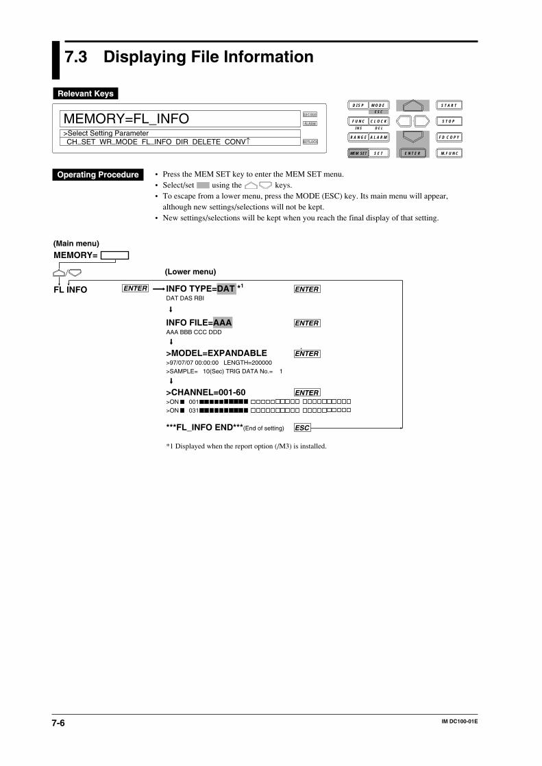
7-6 IM DC100-01E
7.3 Displaying File Information
RECORD
ALARM
KEYLOCK
MEMORY=FL_INFO
CH_SET WR_MODE FL_INFO DIR DELETE CONV↑>Select Setting Parameter
D I S P M O D E
C L O C KF U N C
I N S D E L
R A N G E A L A R M
S E TMEM SET E N T E R
S T O P
F D C O P Y
M. F U N C
S T A R TE S C
• Press the MEM SET key to enter the MEM SET menu.• Select/set using the keys.• To escape from a lower menu, press the MODE (ESC) key. Its main menu will appear,
although new settings/selections will not be kept.• New settings/selections will be kept when you reach the final display of that setting.
INFO TYPE=DAT *1 ENTERDAT DAS RBI
INFO FILE=AAA ENTERAAA BBB CCC DDD
>MODEL=EXPANDABLE ENTER>97/07/07 00:00:00 LENGTH=200000>SAMPLE= 10(Sec) TRIG DATA No.= 1
>CHANNEL=001-60 ENTER>ON 001>ON 031
***FL_INFO END***(End of setting) ESC
*1 Displayed when the report option (/M3) is installed.
MEMORY=
FL INFO
(Main menu)
(Lower menu)
ENTER
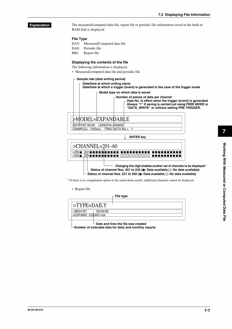
7-7IM DC100-01E
Wo
rking
With
Measu
red o
r Co
mp
uted
Data F
Ile
7
The measured/computed data file, report file or periodic file information saved in the built-inRAM disk is displayed.
File TypeDAT: Measured/Computed data fileDAS: Periodic fileRBI: Report file
Displaying the contents of the fileThe following information is displayed.• Measured/computed data file and periodic file
>MODEL=EXPANDABLE
>SAMPLE= 10(Sec) TRIG DATA No.= 1>97/07/07 00:00 LENGTH=200000
>CHANNEL=201–60>ON 201>ON 231
Model type on which data is saved
Number of pieces of data per channelData No. in effect when the trigger (event) is generatedAlways “1” if saving is carried out using FREE MODE or “DATA_WRITE” or without setting PRE TRIGGER.
Date/time at which writing startsDate/time at which a trigger (event) is generated in the case of the trigger mode
Sample rate (data writing period)
Status of channel Nos. 201 to 230 ( : Data available, : No data available)Status of channel Nos. 231 to 260 ( : Data available, : No data available)
* If there is no computation option in the stand-alone model, additional channels cannot be displayed.
Changing this digit enables another set of channels to be displayed.*
ENTER key
• Report file
>TYPE=DAILY
>EXPAND COUNT=24>98/01/01 00:00:00
Number of extended data for daily and monthly reports
File type
Date and time the file was created
7.3 Displaying File Information
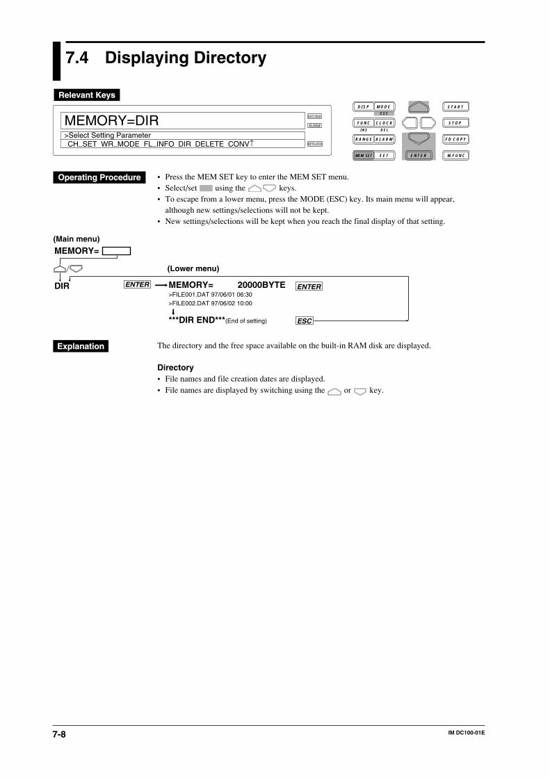
7-8 IM DC100-01E
7.4 Displaying Directory
RECORD
ALARM
KEYLOCK
MEMORY=DIR
CH_SET WR_MODE FL_INFO DIR DELETE CONV↑>Select Setting Parameter
D I S P M O D E
C L O C KF U N C
I N S D E L
R A N G E A L A R M
S E TMEM SET E N T E R
S T O P
F D C O P Y
M. F U N C
S T A R TE S C
• Press the MEM SET key to enter the MEM SET menu.• Select/set using the keys.• To escape from a lower menu, press the MODE (ESC) key. Its main menu will appear,
although new settings/selections will not be kept.• New settings/selections will be kept when you reach the final display of that setting.
MEMORY= 20000BYTE>FILE001.DAT 97/06/01 06:30>FILE002.DAT 97/06/02 10:00
***DIR END***(End of setting)
MEMORY=
DIR
ESC
(Main menu)
(Lower menu)
ENTER ENTER
The directory and the free space available on the built-in RAM disk are displayed.
Directory• File names and file creation dates are displayed.• File names are displayed by switching using the or key.
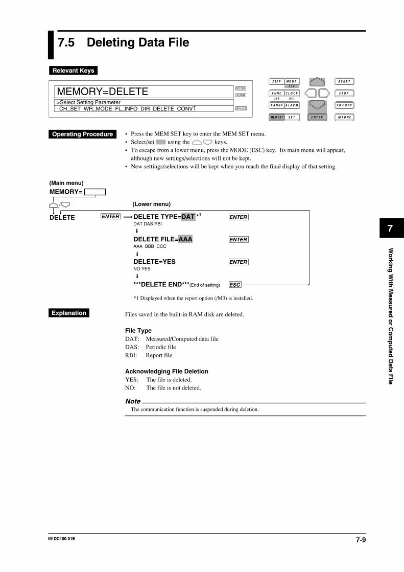
7-9IM DC100-01E
Wo
rking
With
Measu
red o
r Co
mp
uted
Data F
Ile
7
7.5 Deleting Data File
RECORD
ALARM
KEYLOCK
MEMORY=DELETE
CH_SET WR_MODE FL_INFO DIR DELETE CONV↑>Select Setting Parameter
D I S P M O D E
C L O C KF U N C
I N S D E L
R A N G E A L A R M
S E TMEM SET E N T E R
S T O P
F D C O P Y
M. F U N C
S T A R TE S C
• Press the MEM SET key to enter the MEM SET menu.• Select/set using the keys.• To escape from a lower menu, press the MODE (ESC) key. Its main menu will appear,
although new settings/selections will not be kept.• New settings/selections will be kept when you reach the final display of that setting.
DELETE TYPE=DAT *1 ENTERDAT DAS RBI
DELETE FILE=AAA ENTERAAA BBB CCC
DELETE=YES ENTERNO YES
***DELETE END***(End of setting) ESC
*1 Displayed when the report option (/M3) is installed.
MEMORY=
DELETE
(Main menu)
(Lower menu)
ENTER
Files saved in the built-in RAM disk are deleted.
File TypeDAT: Measured/Computed data fileDAS: Periodic fileRBI: Report file
Acknowledging File DeletionYES: The file is deleted.NO: The file is not deleted.
NoteThe communication function is suspended during deletion.
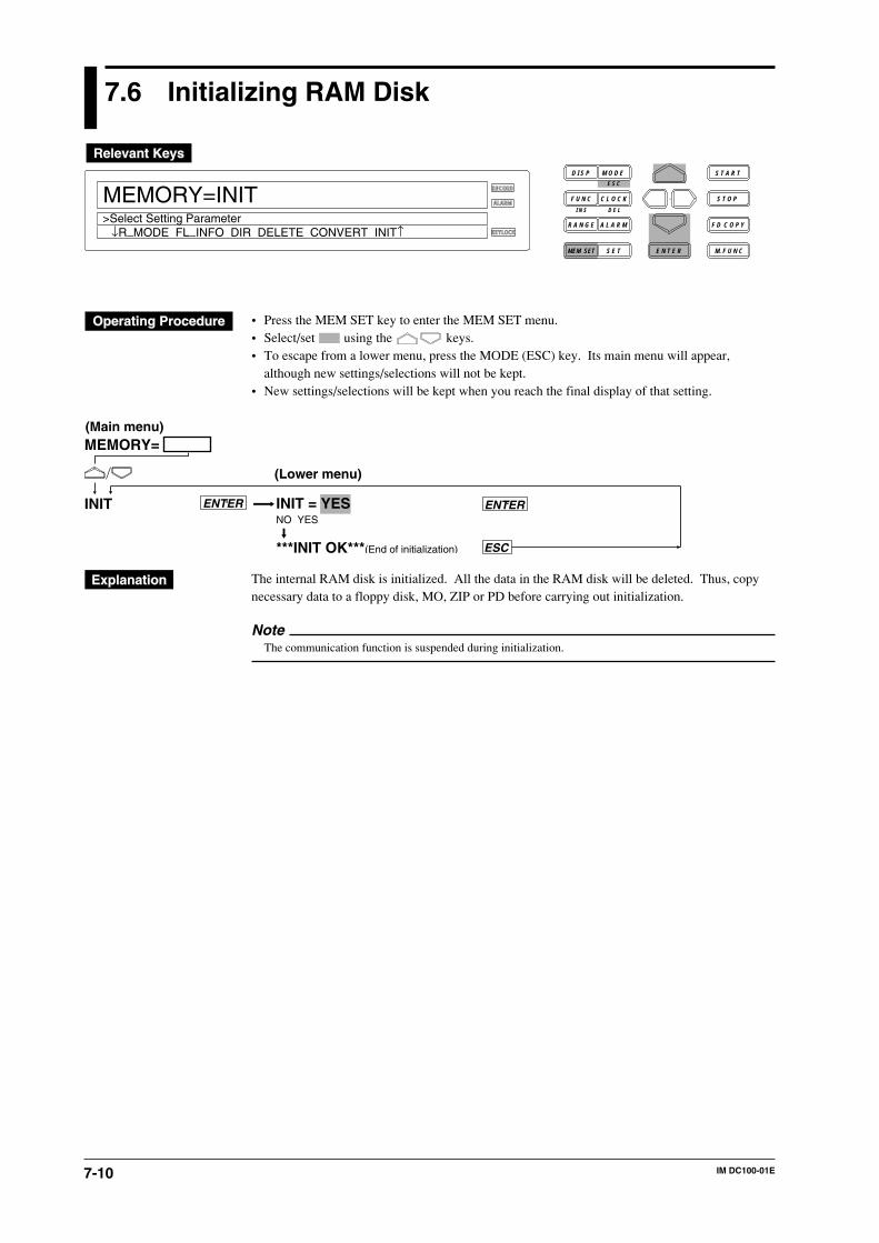
7-10 IM DC100-01E
7.6 Initializing RAM Disk
RECORD
ALARM
KEYLOCK
MEMORY=INIT
↓R_MODE FL_INFO DIR DELETE CONVERT INIT↑>Select Setting Parameter
D I S P M O D E
C L O C KF U N C
I N S D E L
R A N G E A L A R M
S E TMEM SET E N T E R
S T O P
F D C O P Y
M. F U N C
S T A R TE S C
• Press the MEM SET key to enter the MEM SET menu.• Select/set using the keys.• To escape from a lower menu, press the MODE (ESC) key. Its main menu will appear,
although new settings/selections will not be kept.• New settings/selections will be kept when you reach the final display of that setting.
(Main menu)
(Lower menu)
MEMORY=
INIT INIT = YESNO YES
***INIT OK***(End of initialization)
ENTER ENTER
ESC
The internal RAM disk is initialized. All the data in the RAM disk will be deleted. Thus, copynecessary data to a floppy disk, MO, ZIP or PD before carrying out initialization.
NoteThe communication function is suspended during initialization.
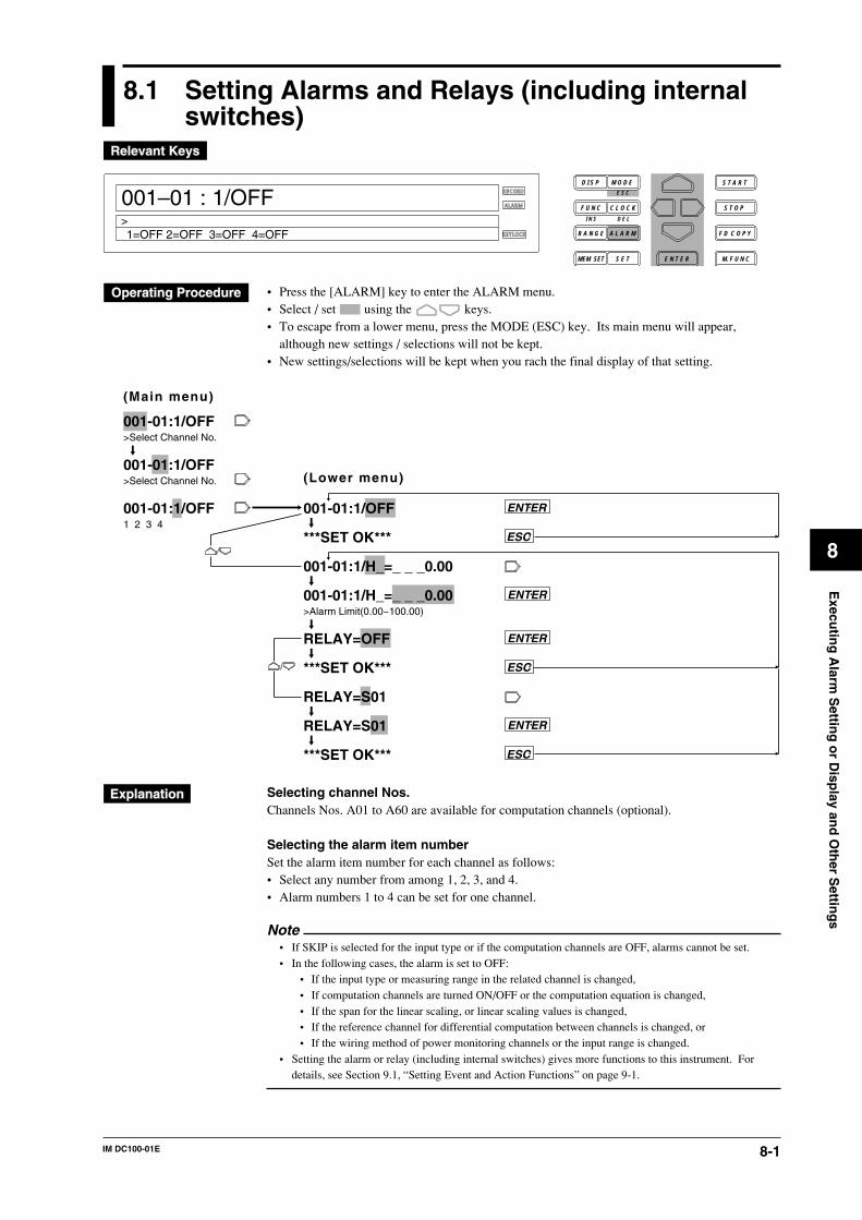
8-1IM DC100-01E
8
Execu
ting
Alarm
Settin
g o
r Disp
lay and
Oth
er Settin
gs
8.1 Setting Alarms and Relays (including internalswitches)
RECORD
ALARM
KEYLOCK
001–01 : 1/OFF
1=OFF 2=OFF 3=OFF 4=OFF>
D I S P M O D E
C L O C KF U N C
I N S D E L
R A N G E A L A R M
S E TMEM SET E N T E R
S T O P
F D C O P Y
M. F U N C
S T A R TE S C
• Press the [ALARM] key to enter the ALARM menu.• Select / set using the keys.• To escape from a lower menu, press the MODE (ESC) key. Its main menu will appear,
although new settings / selections will not be kept.• New settings/selections will be kept when you rach the final display of that setting.
001-01:1/OFF>Select Channel No.
001-01:1/OFF>Select Channel No.
001-01:1/OFF1 2 3 4
001-01:1/OFF
***SET OK***
001-01:1/H_=_ _ _0.00
001-01:1/H_=_ _ _0.00>Alarm Limit(0.00~100.00)
RELAY=OFF
***SET OK***
RELAY=S01
RELAY=S01
***SET OK***
ENTER
ENTER
ENTER
ESC
ESC
ESC
ENTER
(Main menu)
(Lower menu)
Selecting channel Nos.Channels Nos. A01 to A60 are available for computation channels (optional).
Selecting the alarm item numberSet the alarm item number for each channel as follows:• Select any number from among 1, 2, 3, and 4.• Alarm numbers 1 to 4 can be set for one channel.
Note• If SKIP is selected for the input type or if the computation channels are OFF, alarms cannot be set.• In the following cases, the alarm is set to OFF:
• If the input type or measuring range in the related channel is changed,• If computation channels are turned ON/OFF or the computation equation is changed,• If the span for the linear scaling, or linear scaling values is changed,• If the reference channel for differential computation between channels is changed, or• If the wiring method of power monitoring channels or the input range is changed.
• Setting the alarm or relay (including internal switches) gives more functions to this instrument. Fordetails, see Section 9.1, “Setting Event and Action Functions” on page 9-1.
8-2 IM DC100-01E
Selecting the type of alarmSelect an alarm type for each alarm number from among the following:
• OFF (default set): No alarm is set.• H: Upper-limit alarm. An alarm occurs when the measured value exceeds the upper-limit
alarm setpoint.• L: Lower-limit alarm. An alarm occurs when the measured value exceeds the lower-limit
alarm setpoint.• RH: Rate-of-change upper-limit alarm. An alarm occurs when the measured value changes
in the increasing direction within a certain time (rate-of-change alarm interval) and exceedsthe upper-limit alarm setpoint.
• RL: Rate-of-change lower-limit alarm. An alarm occurs when the measured value changesin the decreasing direction within a certain time (rate-of-change alarm interval) and exceedsthe lower-limit alarm setpoint.
• dH: An alarm occurs when the difference between two channels exceeds the upper-limitalarm setpoint. This only applies to a channel for which interchannel differentialcomputation is selected, and can be set as a type of alarm.
• dL: An alarm occurs when the difference between two channels exceeds the lower-limitalarm setpoint. This only applies to a channel for which interchannel differentialcomputation is selected, and can be set as a type of alarm.
• For details on the rate-of-change alarm interval setting or other basic alarm settings, see Section10.3, “Select Alarm Interval/Hystresis/Hold/A/D Converter integration Timer/Filter” on page10-4.
• For details on interchannel differential computation, see Section 5.1, “Setting the Type of Inputand Span” on page 5-3.
• Only H (upper-limit alarm) and L (lower-limit alarm) are available for computation channels.
Setting alarm valuesSet one alarm value for each alarm number within the following range, depending on the type ofinput. The default value is 0 (zero).• H and L
• VOLT, TC, RTD, DI, and DELTA: Within the measuring range in the related channel. DIcan be set to either 0 or 1.
• SCALE: Within a linear scaling value.• Computation channel: Within the range specified by the computation function.
• RH and RL• VOLT, TC, RTD, DI, and DELTA: Within 1 to [maximum measuring range minus
minimum measuring range] in the related channel. For example, set 30000 (without using adecimal point) if the maximum value exceeds 30000. DI can be set to only 1.
• SCALE: Set 1 to 30000 without using a decimal point.• dH and dL
• When the reference channel uses VOLT: Within the measuring range.• When the reference channel uses other than VOLT: [maximum measuring range minus
minimum measuring range] to - [maximum measuring range minus minimum measuringrange]
• For the type of input, see Section 5.1, “Setting the Type of Input and Span” on page 5-3.
NoteWhen setting alarm values in continuous channels, use the decimal point as follows:
The decimal point of an alarm value when the continuous channels have different measuring rangesshould be in the position determined by the individual measuring range. If the decimal point is outsidethe measuring range, an error occurs. For example, if channels with measuring ranges 20 mV and 2 V,and a type T thermocouple channel, are all set to an alarm value of 10000, then the alarm values in therespective channels are as follows:
10.000 mV in the 20 mV measuring range channel1.0000 V in 2 V measuring range channel1000.0°C in the type T thermocouple channel
A type T thermocouple has a measuring range from -200.0 to 400.0°C, so an error results. For details onthe decimal point positions in individual measuring ranges, see Chapter 14, “Specifications.”
8.1 Setting Alarms and Relays (including internal switches)
8-3IM DC100-01E
8
Execu
ting
Alarm
Settin
g o
r Disp
lay and
Oth
er Settin
gs
Setting Relays (Internal Switches)Set which alarm output relay or internal switch should be triggered when an alarm occurs:• Select the desired alarm output relay or internal switch from among the following. The default
setting is OFF.• OFF: Alarm output relays and internal switches remain OFF.• S01 to S60: 60 internal switches are provided.• UMN
U: Unit number for an alarm module or a DI/DO module. M: Slot number for an alarmmodule or a DI/DO module. N: Number 0 to 9. For details, see page 3-8.
• Multiple alarm setpoints can be set for one alarm output relay or internal switch.• The operation mode in the alarm output relay or internal switch can be set when an alarm
occurs. For details, see Section 10.4, “Setting Operation Mode of Relay/Internal Switch” onpage 10-5.
• When the alarm module or DI/DO module is not recognized as system module, the relay is setto OFF. For the system recognition, see page 3-31.
8.1 Setting Alarms and Relays (including internal switches)
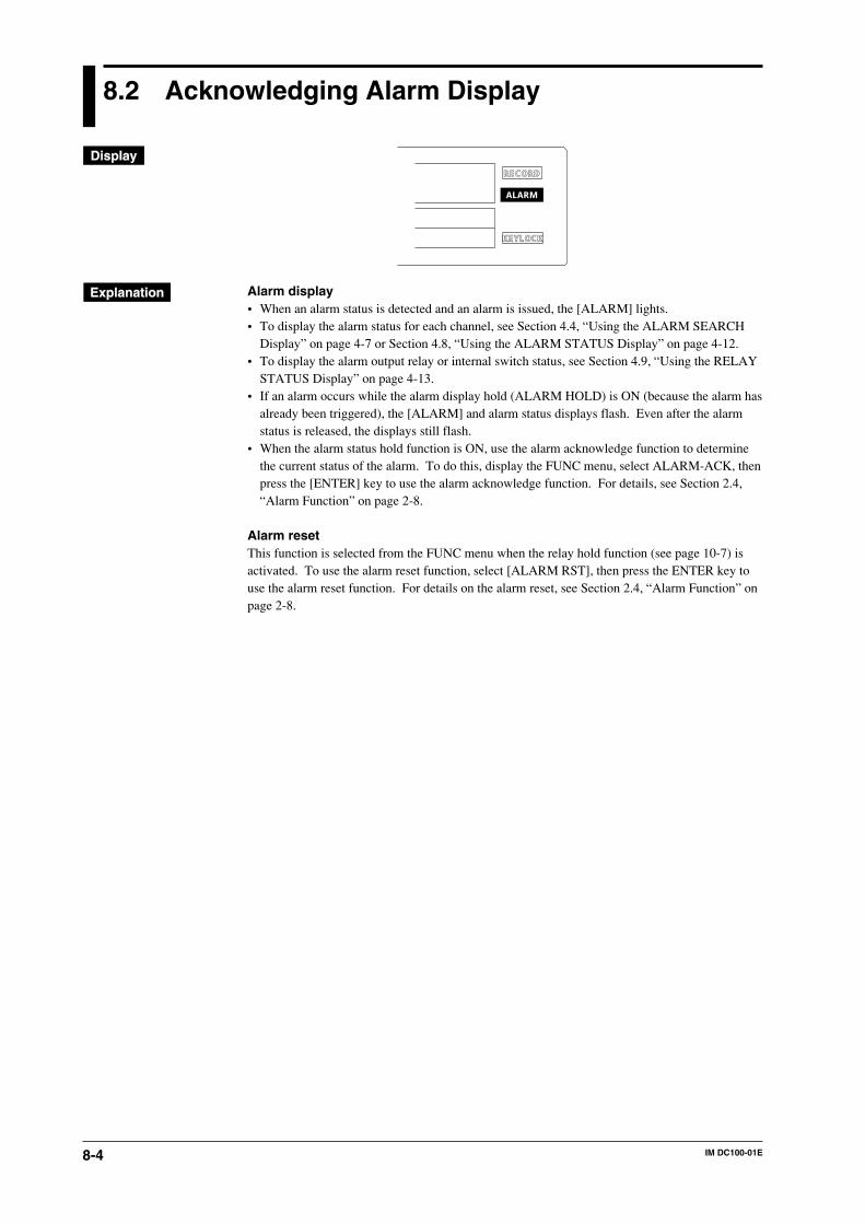
8-4 IM DC100-01E
8.2 Acknowledging Alarm Display
KEYLOCK
RECORD
ALARM
Alarm display• When an alarm status is detected and an alarm is issued, the [ALARM] lights.• To display the alarm status for each channel, see Section 4.4, “Using the ALARM SEARCH
Display” on page 4-7 or Section 4.8, “Using the ALARM STATUS Display” on page 4-12.• To display the alarm output relay or internal switch status, see Section 4.9, “Using the RELAY
STATUS Display” on page 4-13.• If an alarm occurs while the alarm display hold (ALARM HOLD) is ON (because the alarm has
already been triggered), the [ALARM] and alarm status displays flash. Even after the alarmstatus is released, the displays still flash.
• When the alarm status hold function is ON, use the alarm acknowledge function to determinethe current status of the alarm. To do this, display the FUNC menu, select ALARM-ACK, thenpress the [ENTER] key to use the alarm acknowledge function. For details, see Section 2.4,“Alarm Function” on page 2-8.
Alarm resetThis function is selected from the FUNC menu when the relay hold function (see page 10-7) isactivated. To use the alarm reset function, select [ALARM RST], then press the ENTER key touse the alarm reset function. For details on the alarm reset, see Section 2.4, “Alarm Function” onpage 2-8.
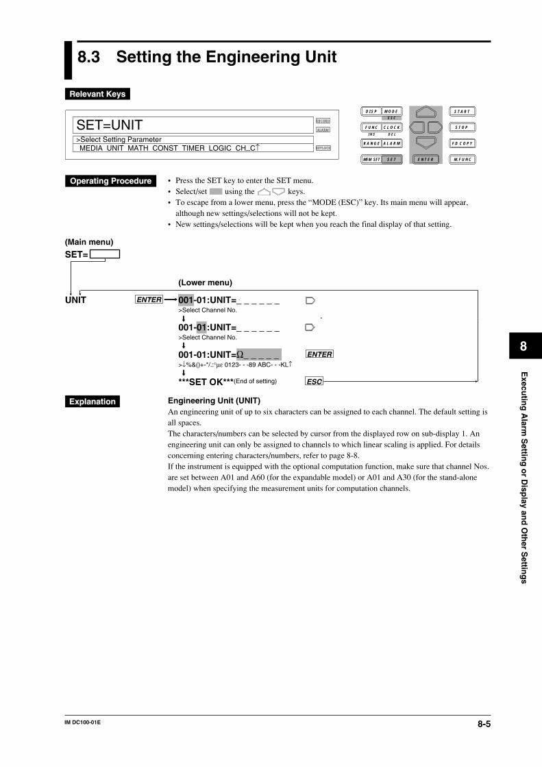
8-5IM DC100-01E
8
Execu
ting
Alarm
Settin
g o
r Disp
lay and
Oth
er Settin
gs
8.3 Setting the Engineering Unit
RECORD
ALARM
KEYLOCK
SET=UNIT
MEDIA UNIT MATH CONST TIMER LOGIC CH_C↑>Select Setting Parameter
D I S P M O D E
C L O C KF U N C
I N S D E L
R A N G E A L A R M
S E TMEM SET E N T E R
S T O P
F D C O P Y
M. F U N C
S T A R TE S C
• Press the SET key to enter the SET menu.• Select/set using the keys.• To escape from a lower menu, press the “MODE (ESC)” key. Its main menu will appear,
although new settings/selections will not be kept.• New settings/selections will be kept when you reach the final display of that setting.
SET=
UNIT ENTER
ENTER
ESC
(Main menu)
(Lower menu)
001-01:UNIT=_ _ _ _ _ _>Select Channel No.
001-01:UNIT=_ _ _ _ _ _>Select Channel No.
001-01:UNIT=Ω_ _ _ _ _>↓%&()+-*/.:°µε 0123- - -89 ABC- - -KL↑
***SET OK***(End of setting)
Engineering Unit (UNIT)An engineering unit of up to six characters can be assigned to each channel. The default setting isall spaces.The characters/numbers can be selected by cursor from the displayed row on sub-display 1. Anengineering unit can only be assigned to channels to which linear scaling is applied. For detailsconcerning entering characters/numbers, refer to page 8-8.If the instrument is equipped with the optional computation function, make sure that channel Nos.are set between A01 and A60 (for the expandable model) or A01 and A30 (for the stand-alonemodel) when specifying the measurement units for computation channels.
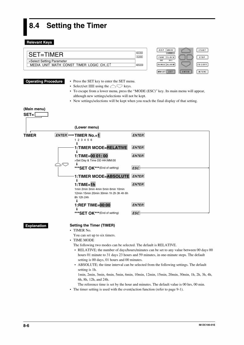
8-6 IM DC100-01E
8.4 Setting the Timer
RECORD
ALARM
KEYLOCK
SET=TIMER
MEDIA UNIT MATH CONST TIMER LOGIC CH_C↑>Select Setting Parameter
D I S P M O D E
C L O C KF U N C
I N S D E L
R A N G E A L A R M
S E TMEM SET E N T E R
S T O P
F D C O P Y
M. F U N C
S T A R TE S C
• Press the SET key to enter the SET menu.• Select/set using the keys.• To escape from a lower menu, press the “MODE (ESC)” key. Its main menu will appear,
although new settings/selections will not be kept.• New settings/selections will be kept when you reach the final display of that setting.
TIMER TIMER No.=11 2 3 4 5 6
1:TIMER MODE=RELATIVE
1:TIME=00 01: 00>Set Day & Time DD HH:MM:00
***SET OK***(End of setting)
1:TIMER MODE=ABSOLUTE
1:TIME=1h1min 2min 3min 4min 5min 6min 10min12min 15min 20min 30min 1h 2h 3h 4h 6h8h 12h 24h
1:REF TIME=00:00
***SET OK***(End of setting)
ENTER
ENTER
ENTER
ENTER
ENTER
ENTER
ESC
ENTER
ESC
SET=(Main menu)
(Lower menu)
Setting the Timer (TIMER)• TIMER No.
You can set up to six timers.• TIME MODE
The following two modes can be selected. The default is RELATIVE.• RELATIVE; the number of days/hours/minutes can be set to any value between 00 days 00
hours 01 minute to 31 days 23 hours and 59 minutes, in one-minute steps. The defaultsetting is 00 days, 01 hours and 00 minutes.
• ABSOLUTE; the time interval can be selected from the following settings. The defaultsetting is 1h.1min, 2min, 3min, 4min, 5min, 6min, 10min, 12min, 15min, 20min, 30min, 1h, 2h, 3h, 4h,6h, 8h, 12h, and 24h.The reference time is set by the hour and minutes. The default value is 00 hrs, 00 min.
• The timer setting is used with the event/action function (refer to page 9-1).

8-7IM DC100-01E
8
Execu
ting
Alarm
Settin
g o
r Disp
lay and
Oth
er Settin
gs
8.5 Setting Tag and Message
RECORD
ALARM
KEYLOCK
SET=TAG
TAG MESSAGE MATCH_TIME MOVE_AVE GROUP↑>Select Setting Parameter
D I S P M O D E
C L O C KF U N C
I N S D E L
R A N G E A L A R M
S E TMEM SET E N T E R
S T O P
F D C O P Y
M. F U N C
S T A R TE S C
• Press the SET key for three seconds to enter the SET3 menu.• Select/set using the keys.• To escape from a lower menu, press the “MODE (ESC)” key. Its main menu will appear,
although new settings/selections will not be kept.• New settings/selections will be kept when you reach the final display of that setting.
001-01:TAG=_ _ _ _ _ _ _ _ >TAG=[_ _ _ _ _ _ _ _ _ _ _ _ _ _ _ _]>Select Channel No.
001-01:TAG=_ _ _ _ _ _ _ _>TAG=[_ _ _ _ _ _ _ _ _ _ _ _ _ _ _ _]>Select Channel No.
001-01:TAG=12345678>TAG=[12345678]↓%&()+-*/.:- - - 0123456789 ABC- - -KL↑
***SET OK***(End of setting)
TAG ENTER
ESC
ENTER
SET=(Main menu)
(Lower menu)
MESSAGE No.=01
MSG01=_ _ _ _ _ _ _ _ _ _ _ _ _ _ _ _>MSG01=[_ _ _ _ _ _ _ _ _ _ _ _ _ _ _ _ ]↓%&()+-*/.:- - - 0123456789 ABC- - -KL↑
MESSAGE No.=02
MSG02=_ _ _ _ _ _ _ _ _ _ _ _ _ _ _ _>MSG02=[_ _ _ _ _ _ _ _ _ _ _ _ _ _ _ _ ]↓%&()+-*/.:- - - 0123456789 ABC- - -KL↑ : : : : : :MESSAGE No.=20
MSG20=_ _ _ _ _ _ _ _ _ _ _ _ _ _ _ _>MSG20=[_ _ _ _ _ _ _ _ _ _ _ _ _ _ _ _ ]↓%&()+-*/.:- - - 0123456789 ABC- - -KL↑
MESSAGE No.=COPY
COPY MSG01 TO MSG0101 02 03 04 05 06 07 08 09 1011 12 13 14 15 16 17 18 19 20
COPY MSG01 TO MSG0201 02 03 04 05 06 07 08 09 1011 12 13 14 15 16 17 18 19 20
MESSAGE ENTERENTER
ENTER
ENTER
ENTER
ENTER
ENTER
ENTER
ESC***SET OK***(End of setting)
ENTER
8-8 IM DC100-01E
Tag SettingA tag of up to 8 characters can be assigned to each channel. If the instrument is equipped with theoptional computation function, this setting can also be made for computation channels A01 toA60 for the expandable model or A01 to A30 for the stand-alone model. The characters/numbersfor the tag can be selected by cursor from the displayed row on sub-display 1. For details on thenumber of characters which will be displayed, refer to 4.1 on page 4-2. To select whether the tagor channel number are displayed, refer to 10.2 on page 10-2. The default settings are all spaces.
Entering a MessageMESSAGE No. (selection of the message No.)
Up to 20 messages can be entered.MSG01 to 20 (entering the message)
The message contents can be entered here using up to 16 characters. Characters and numeralscan be selected from the menu. The default setting is all spaces.
COPY (copying messages)The contents of an entered message (message No. at the left side of the setting) can be copied toanother message number (at the right side of the setting). You cannot copy to the same messagenumber.
Displaying a messageA message can be displayed on the main display using the event/action function.
Inserting/Deleting a Character or NumeralPress the CLOCK(DEL) key to delete a set character or numeral. The digit at the location of thecursor will be deleted.Press the FUNC(INS) key to insert a character or numeral. The digit at the location of the cursorwill become a space, while all the characters/numerals at the right side of the cursor will moveone digit to the right.
8.5 Setting Tag and Message
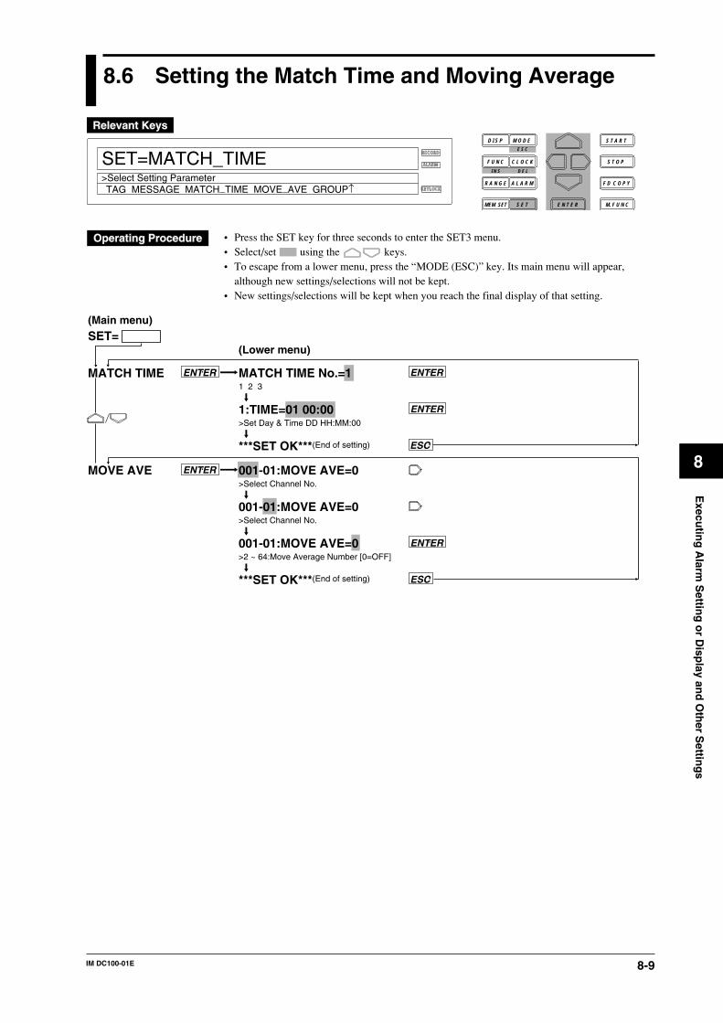
8-9IM DC100-01E
8
Execu
ting
Alarm
Settin
g o
r Disp
lay and
Oth
er Settin
gs
8.6 Setting the Match Time and Moving Average
RECORD
ALARM
KEYLOCK
SET=MATCH_TIME
TAG MESSAGE MATCH_TIME MOVE_AVE GROUP↑>Select Setting Parameter
D I S P M O D E
C L O C KF U N C
I N S D E L
R A N G E A L A R M
S E TMEM SET E N T E R
S T O P
F D C O P Y
M. F U N C
S T A R TE S C
• Press the SET key for three seconds to enter the SET3 menu.• Select/set using the keys.• To escape from a lower menu, press the “MODE (ESC)” key. Its main menu will appear,
although new settings/selections will not be kept.• New settings/selections will be kept when you reach the final display of that setting.
MATCH TIME No.=11 2 3
1:TIME=01 00:00>Set Day & Time DD HH:MM:00
***SET OK***(End of setting)
001-01:MOVE AVE=0>Select Channel No.
001-01:MOVE AVE=0>Select Channel No.
001-01:MOVE AVE=0>2 ~ 64:Move Average Number [0=OFF]
***SET OK***(End of setting)
MATCH TIME
MOVE AVE
ENTER ENTER
ENTER
ESC
ENTER
ESC
ENTER
SET=(Main menu)
(Lower menu)

8-10 IM DC100-01E
Setting the Match Time (MATCH TIME)MATCH TIME No. (selection of the match time number)
Three kinds of match times can be set.TIME
Any time between 00 days, 00 hrs., 00 min. and 31 days, 23 hrs, 59 min. can be set in 1-minuteunits. The default setting is 01 days 00 hrs 00 min.If 00 is set to day (DD), HH:MM every day shows the set time. If day (DD) is set to a valueother than 00, HH:MM of DD day every month shows the set time. DD, HH, and MM give theset numeric values respectively.
The match time setting is used with the event/action function. Refer to 9.1 on page 9-1 for details.
Moving Average (MOVE AVE)This setting can be set for each channel individually. The number of samples used for the movingaverage can be set from 2 to 64. The default value is 0, which means that no moving average iscarried out. The result of the moving average is being displayed.
8.6 Setting the Match Time and Moving Average
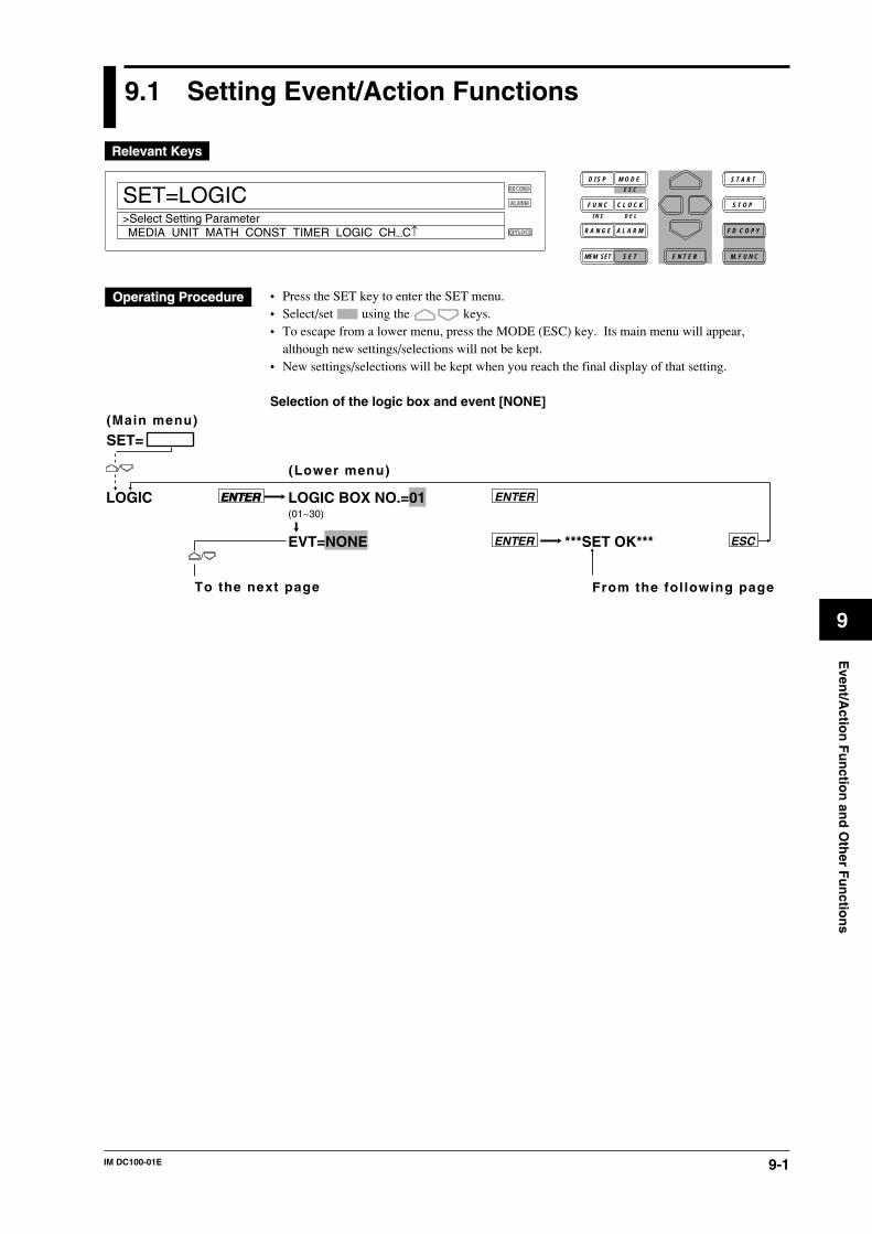
9-1IM DC100-01E
9
Even
t/Actio
n F
un
ction
and
Oth
er Fu
nctio
ns
9.1 Setting Event/Action Functions
RECORD
ALARM
KEYLOCK
SET=LOGIC
MEDIA UNIT MATH CONST TIMER LOGIC CH_C↑>Select Setting Parameter
D I S P M O D E
C L O C KF U N C
I N S D E L
R A N G E A L A R M
S E TMEM SET E N T E R
S T O P
F D C O P Y
M. F U N C
S T A R TE S C
• Press the SET key to enter the SET menu.• Select/set using the keys.• To escape from a lower menu, press the MODE (ESC) key. Its main menu will appear,
although new settings/selections will not be kept.• New settings/selections will be kept when you reach the final display of that setting.
Selection of the logic box and event [NONE]
ENTERLOGIC LOGIC BOX NO.=01(01~30)
EVT=NONE ENTER
ENTER ENTER
ESC***SET OK***
To the next page From the fol lowing page
SET=(Main menu)
(Lower menu)
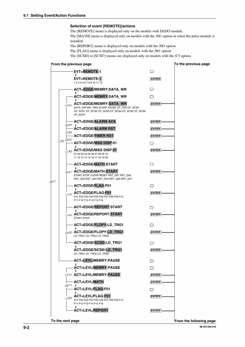
9-2 IM DC100-01E
9.1 Setting Event/Action Functions
Selection of event [REMOTE]/actionsThe [REMOTE] menu is displayed only on the models with DI/DO module.The [MATH] menu is displayed only on models with the /M1 option or when the pulse module isinstalled.The [REPORT] menu is displayed only on models with the /M3 option.The [FLAG] menu is displayed only on models with the /M1 option.The [SCSI0] to [SCSI7] menus are displayed only on models with the /C5 option.
EVT=REMOTE:1
EVT=REMOTE:1 ENTER1 2 3 4 5 6 7 8 9 10 11 12
ACT=EDGE/MEMRY:DATA_WR
ACT=EDGE/MEMRY:DATA_WR
ACT=EDGE/MEMRY:DATA_WR ENTERDATA_WR WR_TRIG START PAUSE CP_FDD CP_SCS0CP_SCS1 CP_SCS2 CP_SCS3 CP_SCS4 CP_SCS5 CP_SCS6CP_SCS7
ACT=EDGE/ALARM ACK ENTER
ACT=EDGE/ALARM RST ENTER
ACT=EDGE/TIMER RST ENTER
ACT=EDGE/MSG DISP:01
ACT=EDGE/MSG DISP:01 ENTER01 02 03 04 05 06 07 08 09 1011 12 13 14 15 16 17 18 19 20
ACT=EDGE/MATH:START
ACT=EDGE/MATH:START ENTERSTART STOP CLEAR RESET RST_G01 RST_G02RST_G03 RST_G04 RST_G05 RST_G06 RST_G07
ACT=EDGE/FLAG:F01
ACT=EDGE/FLAG:F01 ENTERF01 F02 F03 F04 F05 F06 F07 F08 F09 F10F11 F12 F13 F14 F15 F16
ACT=EDGE/REPORT:START
ACT=EDGE/REPORT:START ENTERSTART STOP
ACT=EDGE/FLOPY:LD_TRG1
ACT=EDGE/FLOPY:LD_TRG1 ENTERLD_TRG1 LD_TRG2 LD_TRG3 ACT=EDGE/SCSI0:LD_TRG1
ACT=EDGE/SCSI0:LD_TRG1 ENTERLD_TRG1 LD_TRG2 LD_TRG3
ACT=LEVL/MEMRY:PAUSE
ACT=LEVL/MEMRY:PAUSE
ACT=LEVL/MEMRY:PAUSE ENTER
ACT=LEVL/MATH ENTER
ACT=LEVL/FLAG:F01
ACT=LEVL/FLAG:F01 ENTERF01 F02 F03 F04 F05 F06 F07 F08 F09 F10F11 F12 F13 F14 F15 F16
ACT=LEVL/REPORT ENTER
From the previous page To the previous page
To the next page From the following page
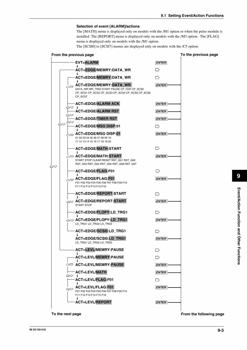
9-3IM DC100-01E
9
Even
t/Actio
n F
un
ction
and
Oth
er Fu
nctio
ns
9.1 Setting Event/Action Functions
Selection of event [ALARM]/actionsThe [MATH] menu is displayed only on models with the /M1 option or when the pulse module isinstalled. The [REPORT] menu is displayed only on models with the /M3 option. The [FLAG]menu is displayed only on models with the /M1 option.The [SCSI0] to [SCSI7] menus are displayed only on models with the /C5 option.
EVT=ALARM ENTER
ACT=EDGE/MEMRY:DATA_WR
ACT=EDGE/MEMRY:DATA_WR
ACT=EDGE/MEMRY:DATA_WR ENTERDATA_WR WR_TRIG START PAUSE CP_FDD CP_SCS0CP_SCS1 CP_SCS2 CP_SCS3 CP_SCS4 CP_SCS5 CP_SCS6CP_SCS7
ACT=EDGE/ALARM ACK ENTER
ACT=EDGE/ALARM RST ENTER
ACT=EDGE/TIMER RST ENTER
ACT=EDGE/MSG DISP:01
ACT=EDGE/MSG DISP:01 ENTER01 02 03 04 05 06 07 08 09 1011 12 13 14 15 16 17 18 19 20
ACT=EDGE/MATH:START
ACT=EDGE/MATH:START ENTERSTART STOP CLEAR RESET RST_G01 RST_G02RST_G03 RST_G04 RST_G05 RST_G06 RST_G07
ACT=EDGE/FLAG:F01
ACT=EDGE/FLAG:F01 ENTERF01 F02 F03 F04 F05 F06 F07 F08 F09 F10F11 F12 F13 F14 F15 F16
ACT=EDGE/REPORT:START
ACT=EDGE/REPORT:START ENTERSTART STOP
ACT=EDGE/FLOPY:LD_TRG1
ACT=EDGE/FLOPY:LD_TRG1 ENTERLD_TRG1 LD_TRG2 LD_TRG3 ACT=EDGE/SCSI0:LD_TRG1
ACT=EDGE/SCSI0:LD_TRG1 ENTERLD_TRG1 LD_TRG2 LD_TRG3
ACT=LEVL/MEMRY:PAUSE
ACT=LEVL/MEMRY:PAUSE
ACT=LEVL/MEMRY:PAUSE ENTER
ACT=LEVL/MATH ENTER
ACT=LEVL/FLAG:F01
ACT=LEVL/FLAG:F01 ENTERF01 F02 F03 F04 F05 F06 F07 F08 F09 F10F11 F12 F13 F14 F15 F16
ACT=LEVL/REPORT ENTER
From the previous page To the previous page
To the next page From the following page
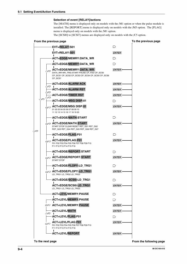
9-4 IM DC100-01E
Selection of event [RELAY]/actionsThe [MATH] menu is displayed only on models with the /M1 option or when the pulse module isinstalled. The [REPORT] menu is displayed only on models with the /M3 option. The [FLAG]menu is displayed only on models with the /M1 option.The [SCSI0] to [SCSI7] menus are displayed only on models with the /C5 option.
EVT=RELAY:S01
EVT=RELAY:S01 ENTER
ACT=EDGE/MEMRY:DATA_WR
ACT=EDGE/MEMRY:DATA_WR
ACT=EDGE/MEMRY:DATA_WR ENTERDATA_WR WR_TRIG START PAUSE CP_FDD CP_SCS0CP_SCS1 CP_SCS2 CP_SCS3 CP_SCS4 CP_SCS5 CP_SCS6CP_SCS7
ACT=EDGE/ALARM ACK ENTER
ACT=EDGE/ALARM RST ENTER
ACT=EDGE/TIMER RST ENTER
ACT=EDGE/MSG DISP:01
ACT=EDGE/MSG DISP:01 ENTER01 02 03 04 05 06 07 08 09 1011 12 13 14 15 16 17 18 19 20
ACT=EDGE/MATH:START
ACT=EDGE/MATH:START ENTERSTART STOP CLEAR RESET RST_G01 RST_G02RST_G03 RST_G04 RST_G05 RST_G06 RST_G07
ACT=EDGE/FLAG:F01
ACT=EDGE/FLAG:F01 ENTERF01 F02 F03 F04 F05 F06 F07 F08 F09 F10F11 F12 F13 F14 F15 F16
ACT=EDGE/REPORT:START
ACT=EDGE/REPORT:START ENTERSTART STOP
ACT=EDGE/FLOPY:LD_TRG1
ACT=EDGE/FLOPY:LD_TRG1 ENTERLD_TRG1 LD_TRG2 LD_TRG3 ACT=EDGE/SCSI0:LD_TRG1
ACT=EDGE/SCSI0:LD_TRG1 ENTERLD_TRG1 LD_TRG2 LD_TRG3
ACT=LEVL/MEMRY:PAUSE
ACT=LEVL/MEMRY:PAUSE
ACT=LEVL/MEMRY:PAUSE ENTER
ACT=LEVL/MATH ENTER
ACT=LEVL/FLAG:F01
ACT=LEVL/FLAG:F01 ENTERF01 F02 F03 F04 F05 F06 F07 F08 F09 F10F11 F12 F13 F14 F15 F16
ACT=LEVL/REPORT ENTER
From the previous page To the previous page
To the next page From the following page
9.1 Setting Event/Action Functions
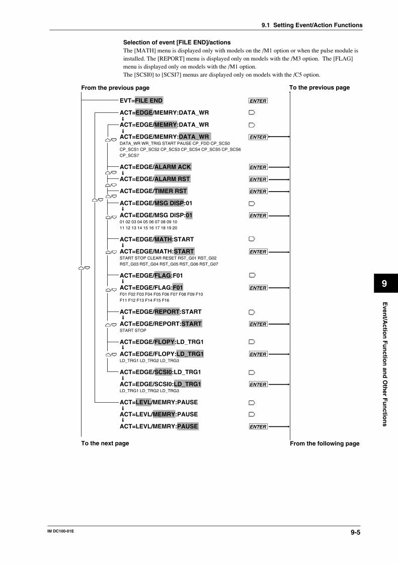
9-5IM DC100-01E
9
Even
t/Actio
n F
un
ction
and
Oth
er Fu
nctio
ns
Selection of event [FILE END]/actionsThe [MATH] menu is displayed only with models on the /M1 option or when the pulse module isinstalled. The [REPORT] menu is displayed only on models with the /M3 option. The [FLAG]menu is displayed only on models with the /M1 option.The [SCSI0] to [SCSI7] menus are displayed only on models with the /C5 option.
EVT=FILE END ENTER
ACT=EDGE/MEMRY:DATA_WR
ACT=EDGE/MEMRY:DATA_WR
ACT=EDGE/MEMRY:DATA_WR ENTERDATA_WR WR_TRIG START PAUSE CP_FDD CP_SCS0CP_SCS1 CP_SCS2 CP_SCS3 CP_SCS4 CP_SCS5 CP_SCS6CP_SCS7
ACT=EDGE/ALARM ACK ENTER
ACT=EDGE/ALARM RST ENTER
ACT=EDGE/TIMER RST ENTER
ACT=EDGE/MSG DISP:01
ACT=EDGE/MSG DISP:01 ENTER01 02 03 04 05 06 07 08 09 1011 12 13 14 15 16 17 18 19 20
ACT=EDGE/MATH:START
ACT=EDGE/MATH:START ENTERSTART STOP CLEAR RESET RST_G01 RST_G02RST_G03 RST_G04 RST_G05 RST_G06 RST_G07
ACT=EDGE/FLAG:F01
ACT=EDGE/FLAG:F01 ENTERF01 F02 F03 F04 F05 F06 F07 F08 F09 F10F11 F12 F13 F14 F15 F16
ACT=EDGE/REPORT:START
ACT=EDGE/REPORT:START ENTERSTART STOP
ACT=EDGE/FLOPY:LD_TRG1
ACT=EDGE/FLOPY:LD_TRG1 ENTERLD_TRG1 LD_TRG2 LD_TRG3 ACT=EDGE/SCSI0:LD_TRG1
ACT=EDGE/SCSI0:LD_TRG1 ENTERLD_TRG1 LD_TRG2 LD_TRG3
ACT=LEVL/MEMRY:PAUSE
ACT=LEVL/MEMRY:PAUSE
ACT=LEVL/MEMRY:PAUSE ENTER
From the previous page To the previous page
To the next page From the following page
9.1 Setting Event/Action Functions
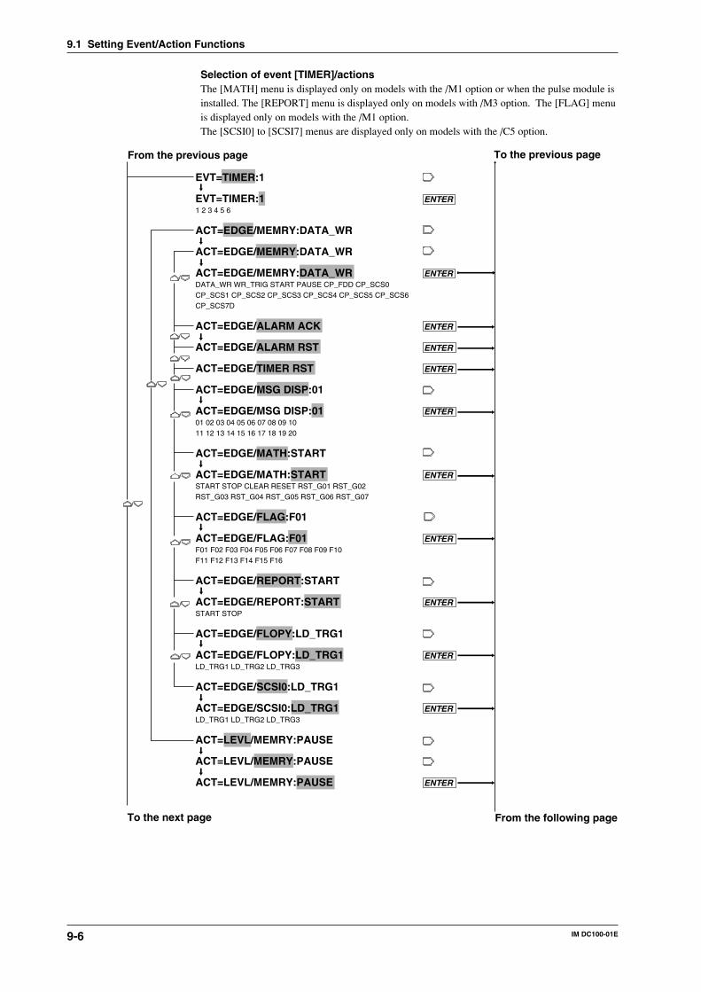
9-6 IM DC100-01E
Selection of event [TIMER]/actionsThe [MATH] menu is displayed only on models with the /M1 option or when the pulse module isinstalled. The [REPORT] menu is displayed only on models with /M3 option. The [FLAG] menuis displayed only on models with the /M1 option.The [SCSI0] to [SCSI7] menus are displayed only on models with the /C5 option.
EVT=TIMER:1
EVT=TIMER:1 ENTER1 2 3 4 5 6
ACT=EDGE/MEMRY:DATA_WR
ACT=EDGE/MEMRY:DATA_WR
ACT=EDGE/MEMRY:DATA_WR ENTERDATA_WR WR_TRIG START PAUSE CP_FDD CP_SCS0CP_SCS1 CP_SCS2 CP_SCS3 CP_SCS4 CP_SCS5 CP_SCS6CP_SCS7D
ACT=EDGE/ALARM ACK ENTER
ACT=EDGE/ALARM RST ENTER
ACT=EDGE/TIMER RST ENTER
ACT=EDGE/MSG DISP:01
ACT=EDGE/MSG DISP:01 ENTER01 02 03 04 05 06 07 08 09 1011 12 13 14 15 16 17 18 19 20
ACT=EDGE/MATH:START
ACT=EDGE/MATH:START ENTERSTART STOP CLEAR RESET RST_G01 RST_G02RST_G03 RST_G04 RST_G05 RST_G06 RST_G07
ACT=EDGE/FLAG:F01
ACT=EDGE/FLAG:F01 ENTERF01 F02 F03 F04 F05 F06 F07 F08 F09 F10F11 F12 F13 F14 F15 F16
ACT=EDGE/REPORT:START
ACT=EDGE/REPORT:START ENTERSTART STOP
ACT=EDGE/FLOPY:LD_TRG1
ACT=EDGE/FLOPY:LD_TRG1 ENTERLD_TRG1 LD_TRG2 LD_TRG3 ACT=EDGE/SCSI0:LD_TRG1
ACT=EDGE/SCSI0:LD_TRG1 ENTERLD_TRG1 LD_TRG2 LD_TRG3
ACT=LEVL/MEMRY:PAUSE
ACT=LEVL/MEMRY:PAUSE
ACT=LEVL/MEMRY:PAUSE ENTER
From the previous page To the previous page
To the next page From the following page
9.1 Setting Event/Action Functions
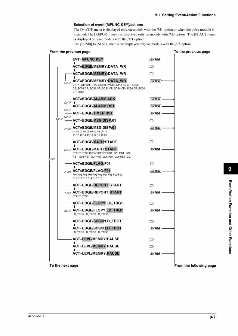
9-7IM DC100-01E
9
Even
t/Actio
n F
un
ction
and
Oth
er Fu
nctio
ns
Selection of event [MFUNC KEY]/actionsThe [MATH] menu is displayed only on models with the /M1 option or when the pulse module isinstalled. The [REPORT] menu is displayed only on models with /M3 option. The [FLAG] menuis displayed only on models with the /M1 option.The [SCSI0] to [SCSI7] menus are displayed only on models with the /C5 option.
EVT=MFUNC KEY ENTER
ACT=EDGE/MEMRY:DATA_WR
ACT=EDGE/MEMRY:DATA_WR
ACT=EDGE/MEMRY:DATA_WR ENTERDATA_WR WR_TRIG START PAUSE CP_FDD CP_SCS0CP_SCS1 CP_SCS2 CP_SCS3 CP_SCS4 CP_SCS5 CP_SCS6CP_SCS7
ACT=EDGE/ALARM ACK ENTER
ACT=EDGE/ALARM RST ENTER
ACT=EDGE/TIMER RST ENTER
ACT=EDGE/MSG DISP:01
ACT=EDGE/MSG DISP:01 ENTER01 02 03 04 05 06 07 08 09 1011 12 13 14 15 16 17 18 19 20
ACT=EDGE/MATH:START
ACT=EDGE/MATH:START ENTERSTART STOP CLEAR RESET RST_G01 RST_G02RST_G03 RST_G04 RST_G05 RST_G06 RST_G07
ACT=EDGE/FLAG:F01
ACT=EDGE/FLAG:F01 ENTERF01 F02 F03 F04 F05 F06 F07 F08 F09 F10F11 F12 F13 F14 F15 F16
ACT=EDGE/REPORT:START
ACT=EDGE/REPORT:START ENTERSTART STOP
ACT=EDGE/FLOPY:LD_TRG1
ACT=EDGE/FLOPY:LD_TRG1 ENTERLD_TRG1 LD_TRG2 LD_TRG3 ACT=EDGE/SCSI0:LD_TRG1
ACT=EDGE/SCSI0:LD_TRG1 ENTERLD_TRG1 LD_TRG2 LD_TRG3
ACT=LEVL/MEMRY:PAUSE
ACT=LEVL/MEMRY:PAUSE
ACT=LEVL/MEMRY:PAUSE ENTER
From the previous page To the previous page
To the next page From the following page
9.1 Setting Event/Action Functions
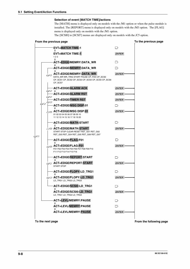
9-8 IM DC100-01E
Selection of event [MATCH TIME]/actionsThe [MATH] menu is displayed only on models with the /M1 option or when the pulse module isinstalled. The [REPORT] menu is displayed only on models with the /M3 option. The [FLAG]menu is displayed only on models with the /M1 option.The [SCSI0] to [SCSI7] menus are displayed only on models with the /C5 option.
EVT=MATCH TIME:1
EVT=MATCH TIME:1 ENTER1 2 3
ACT=EDGE/MEMRY:DATA_WR
ACT=EDGE/MEMRY:DATA_WR
ACT=EDGE/MEMRY:DATA_WR ENTERDATA_WR WR_TRIG START PAUSE CP_FDD CP_SCS0CP_SCS1 CP_SCS2 CP_SCS3 CP_SCS4 CP_SCS5 CP_SCS6CP_SCS7
ACT=EDGE/ALARM ACK ENTER
ACT=EDGE/ALARM RST ENTER
ACT=EDGE/TIMER RST ENTER
ACT=EDGE/MSG DISP:01
ACT=EDGE/MSG DISP:01 ENTER01 02 03 04 05 06 07 08 09 1011 12 13 14 15 16 17 18 19 20
ACT=EDGE/MATH:START
ACT=EDGE/MATH:START ENTERSTART STOP CLEAR RESET RST_G01 RST_G02RST_G03 RST_G04 RST_G05 RST_G06 RST_G07
ACT=EDGE/FLAG:F01
ACT=EDGE/FLAG:F01 ENTERF01 F02 F03 F04 F05 F06 F07 F08 F09 F10F11 F12 F13 F14 F15 F16
ACT=EDGE/REPORT:START
ACT=EDGE/REPORT:START ENTERSTART STOP
ACT=EDGE/FLOPY:LD_TRG1
ACT=EDGE/FLOPY:LD_TRG1 ENTERLD_TRG1 LD_TRG2 LD_TRG3 ACT=EDGE/SCSI0:LD_TRG1
ACT=EDGE/SCSI0:LD_TRG1 ENTERLD_TRG1 LD_TRG2 LD_TRG3
ACT=LEVL/MEMRY:PAUSE
ACT=LEVL/MEMRY:PAUSE
ACT=LEVL/MEMRY:PAUSE ENTER
From the previous page To the previous page
To the next page From the following page
9.1 Setting Event/Action Functions
9-9IM DC100-01E
9
Even
t/Actio
n F
un
ction
and
Oth
er Fu
nctio
ns
When an event is detected, this menu allows you to set and execute a certain action.Selection of logic (LOGIC) box number• Select a box number from among 01 to 30 for storing a combination logic from events to
actions.• If you select the same number as the box number having an event and action already set, and
set another event and action to that box number, the new setting will replace the old one.
Selection of events (EVT)Select any event from among the following:• NONE — releases the event/action setting.• REMOTE
• This menu is displayed only with the DI/DO modules that are recognized as system modules(see page 9-17).
• When a remote control signal is applied, the action is executed.• There are 12 control signals available. Select any control signal from these numbers for
event setting. Remote control signal terminal numbers are applicable for this selection. Seepage 3-18 for the remote control terminal numbers.
• ALARMIf an alarm occurs, the action is executed. See Section 8.1, “Setting Alarms and Relays(including internal switches),” on page 8-1 for setting alarms.
• RELAYIf the selected internal switch or relay is operating, the action is executed. When the alarmmodule or the DI/DO modules are not recognized as system modules (see page 9-17), the relayis set to OFF. See Section 8.1, “Setting Alarms and Relays (including internal switches),” onpage 8-3 for setting internal switches and relays.
• FILE ENDWhen the end of file (the time when the writing operation is terminated and the file is closed) isdetected, the action is executed.
• TIMER• If the selected timer’s set time is up, the action is executed. Six timers are available. Select
any from among these timers. See Section 8.4, “Setting the Timer,” on page 8-6 for thetimer setting provided earlier in this manual.
• In combination with the level action, the action is repeated alternately between executingand stopping each time the timer’s set time is up.
• MFUNC KEY• When the M.FUNC key on the operation panel is pressed, the action is executed.• In combination with the level action, the action is repeated alternately between executing
and stopping each time the M.FUNC key is pressed.• MATCH TIME
• When the set time is reached, the action is executed.• There are three types of applicable MATCH TIMEs. Select any of them. For details, see
Section 8.6, “Setting the Match Time and Moving Average” on page 8-9 provided earlier inthis manual.
• In combination with the level action, the corresponding action is repeated alternatelybetween executing and stopping for each set time.
Selecting edge or level action• Edge action (EDGE)
This action is executed when an event is detected.• Level action (LEVL)
This action is executed when an event is detected. When an event is released, this action willbe canceled.
9.1 Setting Event/Action Functions
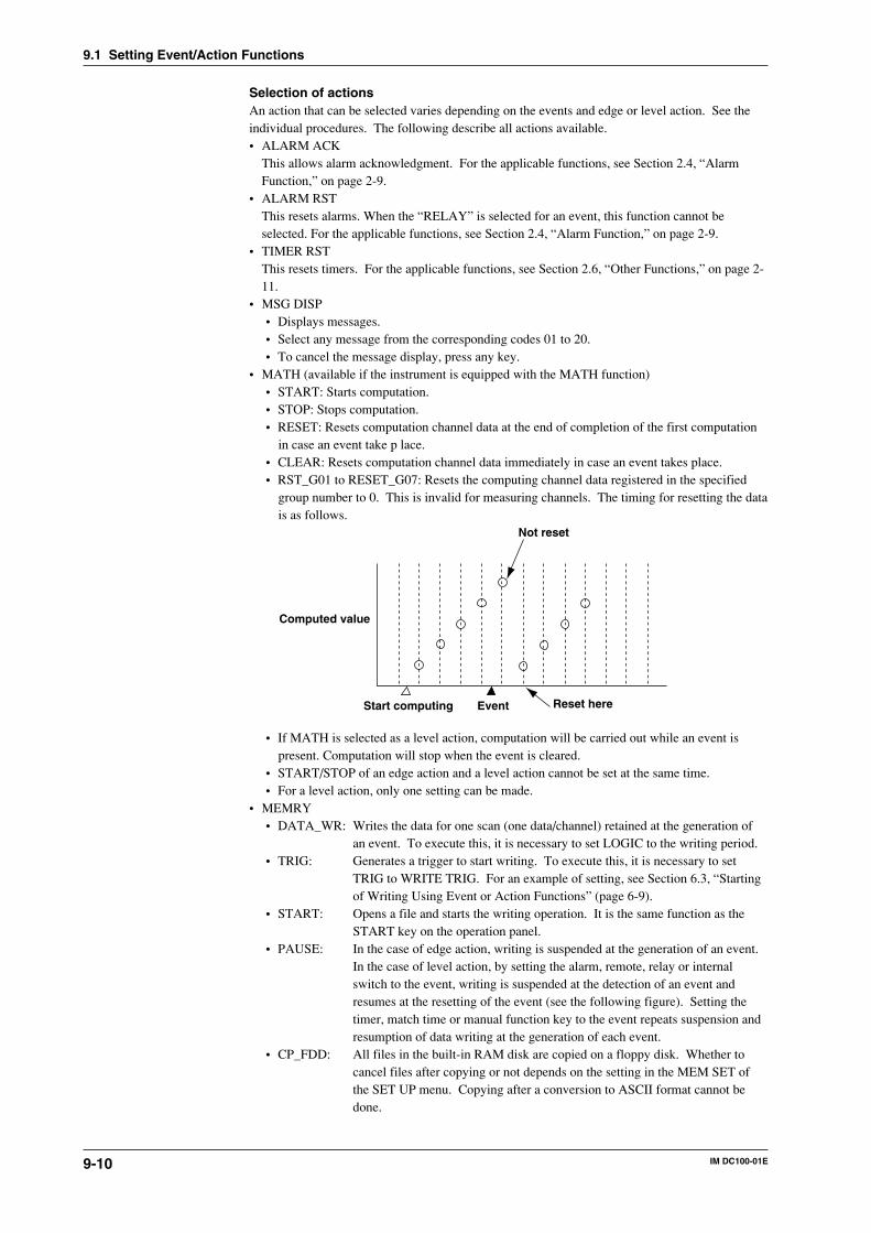
9-10 IM DC100-01E
Selection of actionsAn action that can be selected varies depending on the events and edge or level action. See theindividual procedures. The following describe all actions available.• ALARM ACK
This allows alarm acknowledgment. For the applicable functions, see Section 2.4, “AlarmFunction,” on page 2-9.
• ALARM RSTThis resets alarms. When the “RELAY” is selected for an event, this function cannot beselected. For the applicable functions, see Section 2.4, “Alarm Function,” on page 2-9.
• TIMER RSTThis resets timers. For the applicable functions, see Section 2.6, “Other Functions,” on page 2-11.
• MSG DISP• Displays messages.• Select any message from the corresponding codes 01 to 20.• To cancel the message display, press any key.
• MATH (available if the instrument is equipped with the MATH function)• START: Starts computation.• STOP: Stops computation.• RESET: Resets computation channel data at the end of completion of the first computation
in case an event take p lace.• CLEAR: Resets computation channel data immediately in case an event takes place.• RST_G01 to RESET_G07: Resets the computing channel data registered in the specified
group number to 0. This is invalid for measuring channels. The timing for resetting the datais as follows.
Reset here
Not reset
Computed value
Start computing Event
• If MATH is selected as a level action, computation will be carried out while an event ispresent. Computation will stop when the event is cleared.
• START/STOP of an edge action and a level action cannot be set at the same time.• For a level action, only one setting can be made.
• MEMRY• DATA_WR: Writes the data for one scan (one data/channel) retained at the generation of
an event. To execute this, it is necessary to set LOGIC to the writing period.• TRIG: Generates a trigger to start writing. To execute this, it is necessary to set
TRIG to WRITE TRIG. For an example of setting, see Section 6.3, “Startingof Writing Using Event or Action Functions” (page 6-9).
• START: Opens a file and starts the writing operation. It is the same function as theSTART key on the operation panel.
• PAUSE: In the case of edge action, writing is suspended at the generation of an event.In the case of level action, by setting the alarm, remote, relay or internalswitch to the event, writing is suspended at the detection of an event andresumes at the resetting of the event (see the following figure). Setting thetimer, match time or manual function key to the event repeats suspension andresumption of data writing at the generation of each event.
• CP_FDD: All files in the built-in RAM disk are copied on a floppy disk. Whether tocancel files after copying or not depends on the setting in the MEM SET ofthe SET UP menu. Copying after a conversion to ASCII format cannot bedone.
9.1 Setting Event/Action Functions
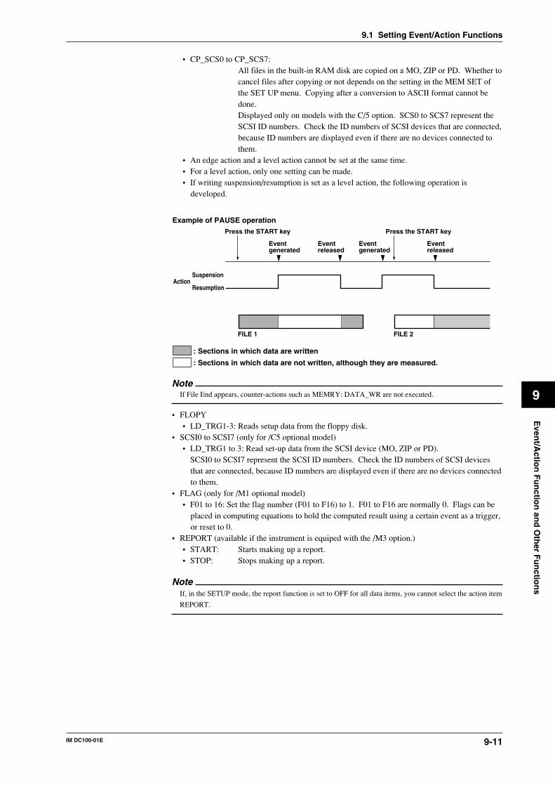
9-11IM DC100-01E
9
Even
t/Actio
n F
un
ction
and
Oth
er Fu
nctio
ns
• CP_SCS0 to CP_SCS7:All files in the built-in RAM disk are copied on a MO, ZIP or PD. Whether tocancel files after copying or not depends on the setting in the MEM SET ofthe SET UP menu. Copying after a conversion to ASCII format cannot bedone.Displayed only on models with the C/5 option. SCS0 to SCS7 represent theSCSI ID numbers. Check the ID numbers of SCSI devices that are connected,because ID numbers are displayed even if there are no devices connected tothem.
• An edge action and a level action cannot be set at the same time.• For a level action, only one setting can be made.• If writing suspension/resumption is set as a level action, the following operation is
developed.
: Sections in which data are written
: Sections in which data are not written, although they are measured.
Press the START key Press the START key
Eventgenerated
Eventgenerated
Eventreleased
Eventreleased
SuspensionAction
Resumption
FILE 1 FILE 2
Example of PAUSE operation
NoteIf File End appears, counter-actions such as MEMRY: DATA_WR are not executed.
• FLOPY• LD_TRG1-3: Reads setup data from the floppy disk.
• SCSI0 to SCSI7 (only for /C5 optional model)• LD_TRG1 to 3: Read set-up data from the SCSI device (MO, ZIP or PD).
SCSI0 to SCSI7 represent the SCSI ID numbers. Check the ID numbers of SCSI devicesthat are connected, because ID numbers are displayed even if there are no devices connectedto them.
• FLAG (only for /M1 optional model)• F01 to 16: Set the flag number (F01 to F16) to 1. F01 to F16 are normally 0. Flags can be
placed in computing equations to hold the computed result using a certain event as a trigger,or reset to 0.
• REPORT (available if the instrument is equiped with the /M3 option.)• START: Starts making up a report.• STOP: Stops making up a report.
NoteIf, in the SETUP mode, the report function is set to OFF for all data items, you cannot select the action item
REPORT.
9.1 Setting Event/Action Functions
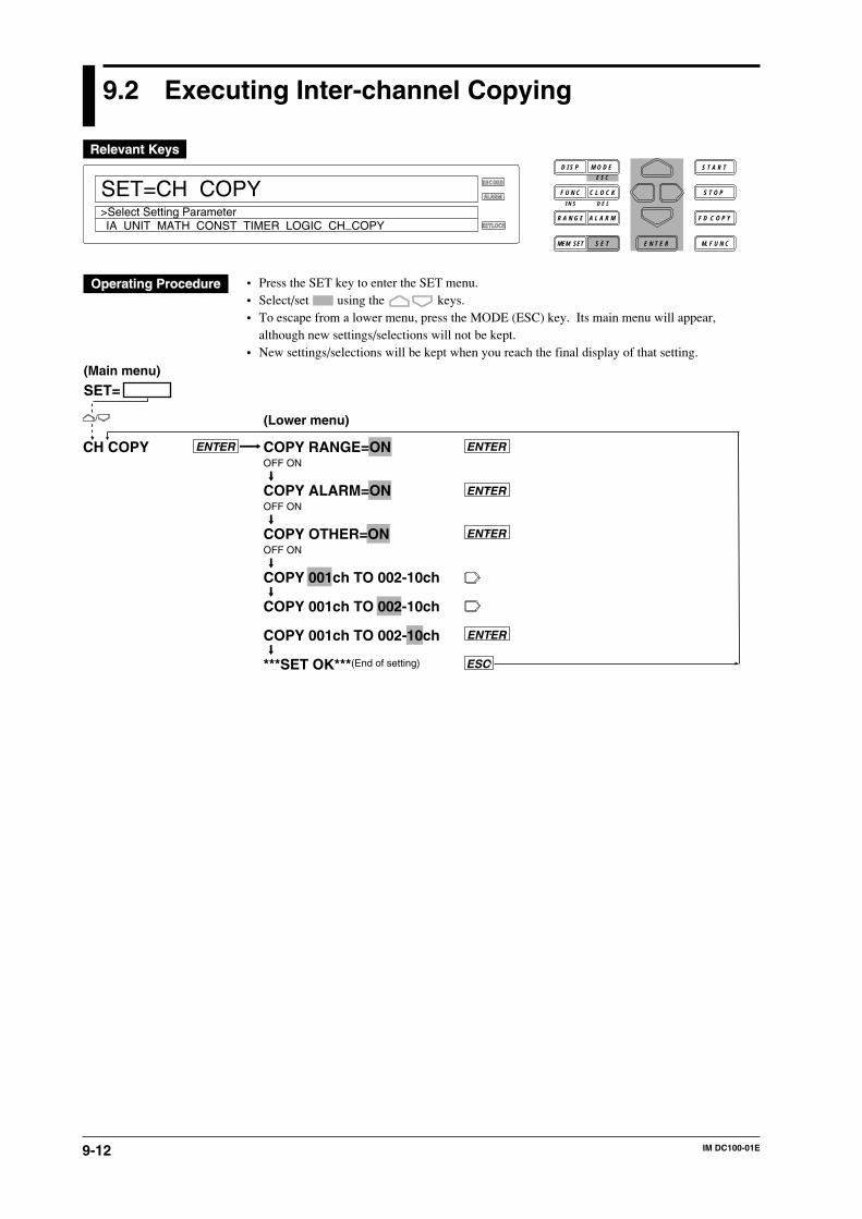
9-12 IM DC100-01E
9.2 Executing Inter-channel Copying
RECORD
ALARM
KEYLOCK
SET=CH COPY
IA UNIT MATH CONST TIMER LOGIC CH_COPY>Select Setting Parameter
D I S P M O D E
C L O C KF U N C
I N S D E L
R A N G E A L A R M
S E TMEM SET E N T E R
S T O P
F D C O P Y
M. F U N C
S T A R TE S C
• Press the SET key to enter the SET menu.• Select/set using the keys.• To escape from a lower menu, press the MODE (ESC) key. Its main menu will appear,
although new settings/selections will not be kept.• New settings/selections will be kept when you reach the final display of that setting.
COPY RANGE=ONOFF ON
COPY ALARM=ONOFF ON
COPY OTHER=ONOFF ON
COPY 001ch TO 002-10ch
COPY 001ch TO 002-10ch
COPY 001ch TO 002-10ch
***SET OK***(End of setting)
CH COPY
ENTER
ENTER
ENTER
ENTER
ENTER
ESC
SET=(Main menu)
(Lower menu)
9-13IM DC100-01E
9
Even
t/Actio
n F
un
ction
and
Oth
er Fu
nctio
ns
Selecting range copying (COPY RANGE)• ON: Copies the type of input, measuring ranges, spans, linear scaling, engineering units, and
tags set.• OFF: The copying of ranges is disabled.Selecting alarm copying (COPY ALARM)• ON: Copies the type of alarm, alarm values, and relay (internal switch) setting.• OFF: The copying of alarms is disabled.Selecting copying of other items (COPY OTHER)• ON: Copies setting average numbers in moving averages and measured data writing ON/OFF.• OFF: The copying of other items is disabled.Setting a copy-source channelSets a copy-source channel with up to three characters. For details on these characters, see thefigure in Section 4-1, “Using the AUTO Display,” on page 4-2.Setting a destination channel to be copiedSets a channel to which the setting data in the source channel are copied.• When the COPY RANGE, COPY ALARM and COPY OTHER are set to ON, individual set
data are copied.• For the setting of a destination channel number, see Section 5.1, “Setting the Type of Input and
Span,” on page 5-2.• It is not possible to copy data between measurement channels and computation channels.Copying Data from a Computation ChannelWhen copying from an optional computation channel is carried out, the following data will becopied.• When COPY RANGE is ON : Computation equation, tag• When COPY ALARM is ON : Alarm• When COPY OTHER is ON : measured data writing ON/OFF
NoteWhen writing the measured/computed data, you are not allowed to copy from channel to channel by setting
COPY RANGE or COPY OTHER to “ON.”
9.2 Executing Inter-channel Copying
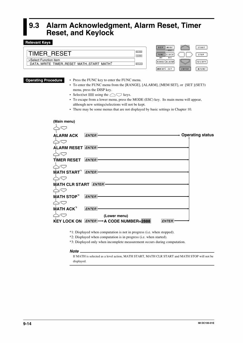
9-14 IM DC100-01E
9.3 Alarm Acknowledgment, Alarm Reset, TimerReset, and Keylock
RECORD
ALARM
KEYLOCK
TIMER_RESET>Select Function item
D I S P M O D E
C L O C KF U N C
I N S D E L
R A N G E A L A R M
S E TMEM SET E N T E R
S T O P
F D C O P Y
M. F U N C
S T A R TE S C
DATA_WRITE TIMER_RESET MATH_START MATH↑
• Press the FUNC key to enter the FUNC menu.• To enter the FUNC menu from the [RANGE], [ALARM], [MEM SET], or [SET ](SET3)
menu, press the DISP key.• Select/set using the keys.• To escape from a lower menu, press the MODE (ESC) key. Its main menu will appear,
although new settings/selections will not be kept.• There may be some menus that are not displayed by basic settings in Chapter 10.
ALARM ACK
ALARM RESET
TIMER RESET
MATH START*1
MATH CLR START
MATH STOP*2
MATH ACK*3
KEY LOCK ON
ENTER Operating status
ENTER
ENTER
(Main menu)
(Lower menu)
A CODE NUMBER=2888ENTER ENTER
ENTER
ENTER
ENTER
ENTER
*1: Displayed when computation is not in progress (i.e. when stopped).*2: Displayed when computation is in progress (i.e. when started).*3: Displayed only when incomplete measurement occurs during computation.
NoteIf MATH is selected as a level action, MATH START, MATH CLR START and MATH STOP will not be
displayed.
9-15IM DC100-01E
9
Even
t/Actio
n F
un
ction
and
Oth
er Fu
nctio
ns
Any of the following functions are executed by pressing the ENTER key. After that, theinstrument returns to the operation mode.
Alarm acknowledgment (ALARM ACK)• When the alarm display hold (ALARM HOLD), on page 10-4 is set to ON, the alarm
acknowledgment menu appears.• For the alarm display hold functions, see Section 2.4, “Alarm Function,” on page 2-9.Alarm reset (ALARM RESET)• When the relay hold function (on page 10-7) is set to ON, the alarm reset menu appears.• For the alarm reset functions, see Section 2.4, “Alarm Function,” on page 2-9.Timer reset (TIMER RESET)• For the timer reset functions, see Section 2.6, “Other Functions,” on page 2-11.Computation start (MATH START)• Starts computation. For details, refer to Chapter 12, “Executing Computation”.Computation clear start (MATH CLR START)• Clears computation results and then re-starts computation.Computation stop (MATH STOP)• Stops computation.Clearing Incomplete Measurement Status (MATH ACK)• Clears the status indication displayed due to incomplete measurement which occurred during
computation.Keylock function (KEY LOCK ON)• For the keylock functions, see Section 2.6, “Other Functions,” on page 2-11.• The KEY LOCK ON is displayed after selecting the keylock (see page 10-13).• Enter a password (A CODE NUMBER) and then press the ENTER key to actuate the keylock
functions. The KEY LOCK OFF menu then appears.• Reenter into the FUNC menu, select KEY LOCK OFF and then enter a password (A CODE
NUMBER). Press the ENTER key to release the keylock functions. The menu returns to KEYLOCK ON.
• To set a password, see page 10-13.• When the keylock functions are actuated, the “KEYLOCK” lights up.
9.3 Alarm Acknowledgment, Alarm Reset, Timer Reset, and Keylock
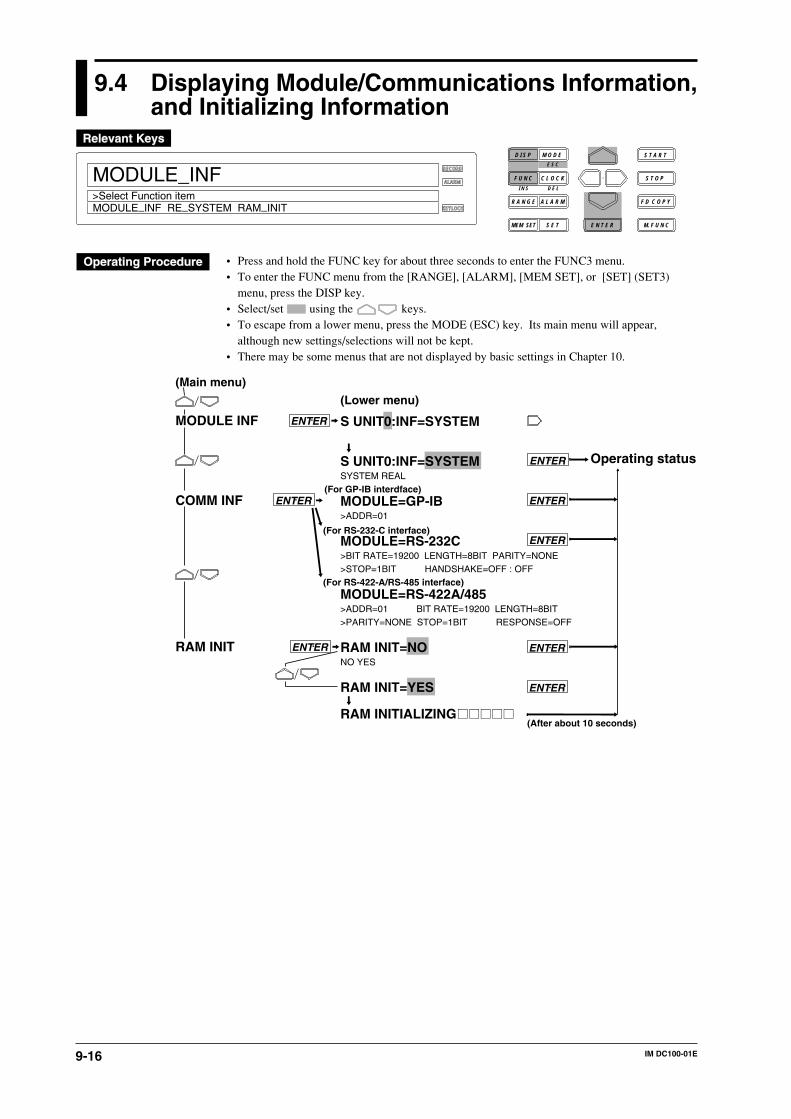
9-16 IM DC100-01E
9.4 Displaying Module/Communications Information,and Initializing Information
RECORD
ALARM
KEYLOCK
MODULE_INF>Select Function itemMODULE_INF RE_SYSTEM RAM_INIT
D I S P M O D E
C L O C KF U N C
I N S D E L
R A N G E A L A R M
S E TMEM SET E N T E R
S T O P
F D C O P Y
M. F U N C
S T A R TE S C
• Press and hold the FUNC key for about three seconds to enter the FUNC3 menu.• To enter the FUNC menu from the [RANGE], [ALARM], [MEM SET], or [SET] (SET3)
menu, press the DISP key.• Select/set using the keys.• To escape from a lower menu, press the MODE (ESC) key. Its main menu will appear,
although new settings/selections will not be kept.• There may be some menus that are not displayed by basic settings in Chapter 10.
MODULE INF
COMM INF
RAM INIT
S UNIT0:INF=SYSTEM
S UNIT0:INF=SYSTEMSYSTEM REAL
MODULE=GP-IB>ADDR=01
MODULE=RS-232C>BIT RATE=19200 LENGTH=8BIT PARITY=NONE>STOP=1BIT HANDSHAKE=OFF : OFF
MODULE=RS-422A/485>ADDR=01 BIT RATE=19200 LENGTH=8BIT>PARITY=NONE STOP=1BIT RESPONSE=OFF
RAM INIT=NONO YES
RAM INIT=YES
RAM INITIALIZING
Operating status
ENTER
ENTER
ENTER
ENTER
ENTER
(After about 10 seconds)
ENTER
ENTER(For GP-IB interdface)
(For RS-232-C interface)
(For RS-422-A/RS-485 interface)
ENTER
(Lower menu)
(Main menu)
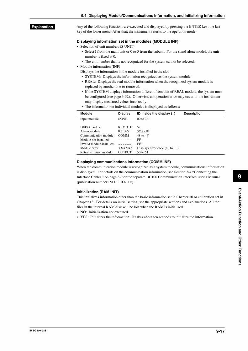
9-17IM DC100-01E
9
Even
t/Actio
n F
un
ction
and
Oth
er Fu
nctio
ns
Any of the following functions are executed and displayed by pressing the ENTER key, the lastkey of the lower menu. After that, the instrument returns to the operation mode.
Displaying information set in the modules (MODULE INF)• Selection of unit numbers (S UNIT)
• Select I from the main unit or 0 to 5 from the subunit. For the stand-alone model, the unitnumber is fixed at 0.
• The unit number that is not recognized for the system cannot be selected.• Module information (INF)
Displays the information in the module installed in the slot.• SYSTEM: Displays the information recognized as the system module.• REAL: Displays the real module information when the recognized system module is
replaced by another one or removed.• If the SYSTEM displays information different from that of REAL module, the system must
be configured (see page 3-32). Otherwise, an operation error may occur or the instrumentmay display measured values incorrectly.
• The information on individual modules is displayed as follows:
Module Display ID inside the display ( ) Description
Input module INPUT 00 to 3F
DI/DO module REMOTE 57Alarm module RELAY 5C to 5FCommunication module COMM 48 to 4FModule not installed –––––– FFInvalid module installed ====== FEModule error XXXXXX Displays error code (80 to FF).Retransmission module OUTPUT 50 to 51
Displaying communications information (COMM INF)When the communication module is recognized as a system module, communications informationis displayed. For details on the communication information, see Section 3-4 “Connecting theInterface Cables,” on page 3-9 or the separate DC100 Communication Interface User’s Manual(publication number IM DC100-11E).
Initialization (RAM INIT)This initializes information other than the basic information set in Chapter 10 or calibration set inChapter 13. For details on initial setting, see the appropriate sections and explanations. All thefiles in the internal RAM disk will be lost when the RAM is initialized.• NO: Initialization not executed.• YES: Initializes the information. It takes about ten seconds to initialize the information.
9.4 Displaying Module/Communications Information, and Initializing Information

9-18 IM DC100-01E
9.5 Fail/File Alarm Output, and Remote ControlSignal Input
FunctionSee Section 2.6, “Other Functions,” on page 2-12.
Connections and NoticeSee Section 3.6, “Connecting the Signal Lines,” on page 3-15.
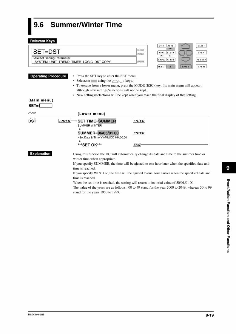
9-19IM DC100-01E
9
Even
t/Actio
n F
un
ction
and
Oth
er Fu
nctio
ns
9.6 Summer/Winter Time
RECORD
ALARM
KEYLOCK
SET=DST
SYSTEM UNIT TREND TIMER LOGIC DST COPY>Select Setting Parameter
D I S P M O D E
C L O C KF U N C
I N S D E L
R A N G E A L A R M
S E TMEM SET E N T E R
S T O P
F D C O P Y
M. F U N C
S T A R TE S C
• Press the SET key to enter the SET menu.• Select/set using the keys.• To escape from a lower menu, press the MODE (ESC) key. Its main menu will appear,
although new settings/selections will not be kept.• New settings/selections will be kept when you reach the final display of that setting.
SET TIME=SUMMERSUMMER WINTER
SUMMER=96/05/01 00>Set Data & Time YY/MM/DD HH:00:00
***SET OK***
DST
ENTER
ENTERENTER
ESC
SET=(Main menu)
(Lower menu)
Using this funcion the DC will automatically change its date and time to the summer time orwinter time when appropriate.If you specify SUMMER, the time will be ajusted to one hour later when the specified date andtime is reached.If you specify WINTER, the time will be ajusted to one hour earlier when the specified date andtime is reached.When the set time is reached, the setting will return to its intial value of 50/01/01 00.The value of the years are as follows : 00 to 49 stand for the year 2000 to 2049, whereas 50 to 99stand for the years 1950 to 1999.

10-1IM DC100-01E
10
Basic S
etting
s (SE
T U
P)
10.1 Selecting Scan Interval
RECORD
ALARM
KEYLOCK
SETUP=SCAN_INTVL
SCAN_INTVL CH/TAG MEM_SET MATH MEDIA A↑>Select Setting Parameter
D I S P M O D E
C L O C KF U N C
I N S D E L
R A N G E A L A R M
S E TMEM SET E N T E R
S T O P
F D C O P Y
M. F U N C
S T A R TE S C
• Enter the SET UP menu in the following procedure:1. When the display presents the operation display mode or a menu other than the SET UP
menu, first turn off the power switch.2. Turn the switch back on while pressing the DISP key and continue pressing the DISP key
for about 5 seconds.• Select/set using the keys.• If exiting the following lower menu setting halfway, press the MODE (ESC) key. The display
returns to the main menu to which the lower menu belongs. However, newly set or selectedcontents are canceled.
• When setting proceeds to the display for the setting end, the newly set or selected contents areestablished.
SET UP=
SCAN INTVL SCAN INTERVAL=0.5(sec)0.5 1 2 3 4 5 6 10 12 15 20 30 60
***SCAN INTVL SET***(End of setting)
ENTERENTER
ESC
(Main menu)
(Lower menu)
Selection of Scan Interval (SCAN INTVL)• Select 0.5, 1, 2, 3, 4, 5, 6, 10, 12, 15, 20, 30 and 60 seconds as the interval.• The default setting is 0.5 seconds.• The shortest selectable scan interval varies with the setting of the number of input channels, A/
D converter integration time, or filter ON/OFF. For details, see chapter 14.
Note• In order to make the set or selected contents effective, the contents must be registered. For details, see
page 10-20.• To return from the SET UP menu to the operation display mode, select END in the main menu. For
details, see page 10-20.• If the writing period is not an integer multiple of the scan interval, the writing period is changed to
INTVL when executing STORE.
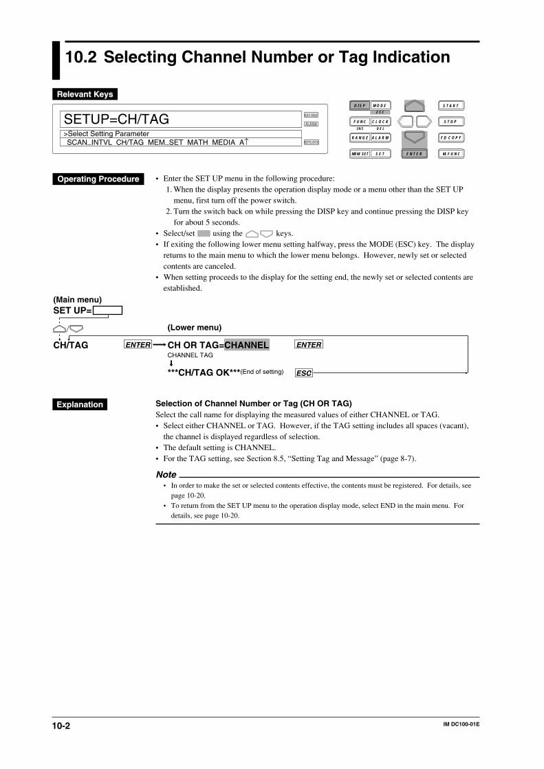
10-2 IM DC100-01E
10.2 Selecting Channel Number or Tag Indication
RECORD
ALARM
KEYLOCK
SETUP=CH/TAG
SCAN_INTVL CH/TAG MEM_SET MATH MEDIA A↑>Select Setting Parameter
D I S P M O D E
C L O C KF U N C
I N S D E L
R A N G E A L A R M
S E TMEM SET E N T E R
S T O P
F D C O P Y
M. F U N C
S T A R TE S C
• Enter the SET UP menu in the following procedure:1. When the display presents the operation display mode or a menu other than the SET UP
menu, first turn off the power switch.2. Turn the switch back on while pressing the DISP key and continue pressing the DISP key
for about 5 seconds.• Select/set using the keys.• If exiting the following lower menu setting halfway, press the MODE (ESC) key. The display
returns to the main menu to which the lower menu belongs. However, newly set or selectedcontents are canceled.
• When setting proceeds to the display for the setting end, the newly set or selected contents areestablished.
SET UP=
CH OR TAG=CHANNELCHANNEL TAG
***CH/TAG OK***(End of setting)
ENTERENTER
ESC
CH/TAG
(Main menu)
(Lower menu)
Selection of Channel Number or Tag (CH OR TAG)Select the call name for displaying the measured values of either CHANNEL or TAG.• Select either CHANNEL or TAG. However, if the TAG setting includes all spaces (vacant),
the channel is displayed regardless of selection.• The default setting is CHANNEL.• For the TAG setting, see Section 8.5, “Setting Tag and Message” (page 8-7).
Note• In order to make the set or selected contents effective, the contents must be registered. For details, see
page 10-20.• To return from the SET UP menu to the operation display mode, select END in the main menu. For
details, see page 10-20.
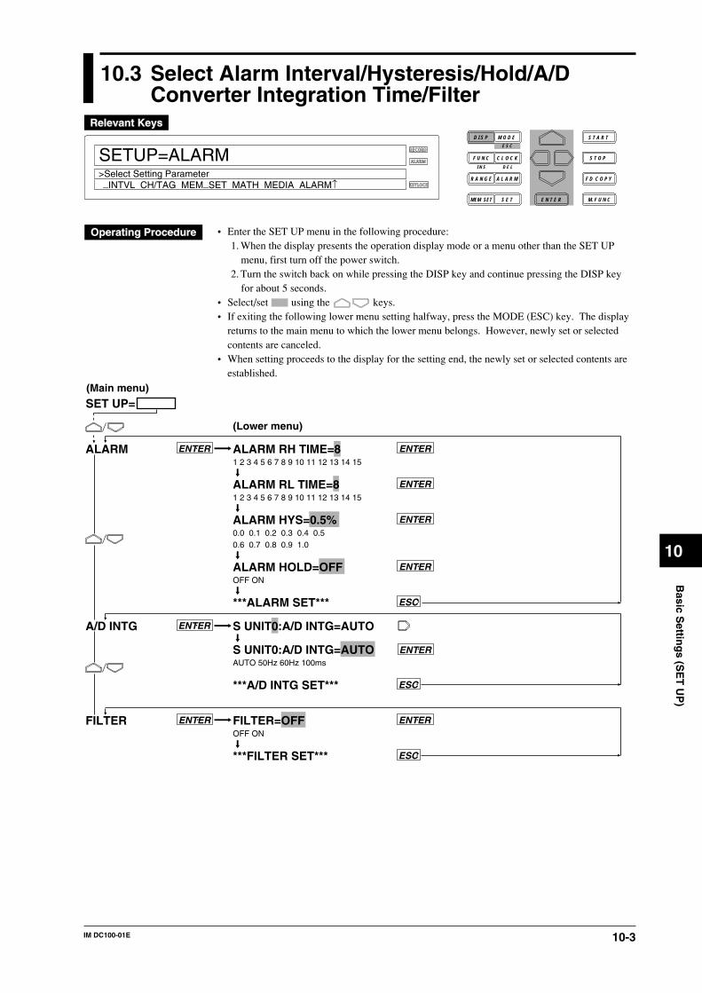
10-3IM DC100-01E
10
Basic S
etting
s (SE
T U
P)
10.3 Select Alarm Interval/Hysteresis/Hold/A/DConverter Integration Time/Filter
RECORD
ALARM
KEYLOCK
SETUP=ALARM
_INTVL CH/TAG MEM_SET MATH MEDIA ALARM↑>Select Setting Parameter
D I S P M O D E
C L O C KF U N C
I N S D E L
R A N G E A L A R M
S E TMEM SET E N T E R
S T O P
F D C O P Y
M. F U N C
S T A R TE S C
• Enter the SET UP menu in the following procedure:1. When the display presents the operation display mode or a menu other than the SET UP
menu, first turn off the power switch.2. Turn the switch back on while pressing the DISP key and continue pressing the DISP key
for about 5 seconds.• Select/set using the keys.• If exiting the following lower menu setting halfway, press the MODE (ESC) key. The display
returns to the main menu to which the lower menu belongs. However, newly set or selectedcontents are canceled.
• When setting proceeds to the display for the setting end, the newly set or selected contents areestablished.
ALARM RH TIME=8 1 2 3 4 5 6 7 8 9 10 11 12 13 14 15
ALARM RL TIME=8 1 2 3 4 5 6 7 8 9 10 11 12 13 14 15
ALARM HYS=0.5% 0.0 0.1 0.2 0.3 0.4 0.5 0.6 0.7 0.8 0.9 1.0
ALARM HOLD=OFFOFF ON
***ALARM SET***
S UNIT0:A/D INTG=AUTO
S UNIT0:A/D INTG=AUTOAUTO 50Hz 60Hz 100ms
***A/D INTG SET***
FILTER=OFFOFF ON
***FILTER SET***
ESC
ENTER
ENTER
ENTER
ENTER
ENTER
ENTER
ENTERENTER
ESC
ESC
ALARM
A/D INTG
FILTER
(Main menu)
(Lower menu)
ENTER
SET UP=
10-4 IM DC100-01E
10.3 Select Alarm Interval/Hysteresis/Hold/A/D Converter Integration Time/Filter
Selection of Interval for High Limit of Rate-Of-Change Alarm (ALARM RH TIME)Set the number of measurement repeats in “Interval = measurement interval x measurementrepeats.”• Select 1, 2, 3, 4, 5, 6, 7, 8, 9, 10, 11, 12, 13, 14, or 15.• The default setting is 8.Selection of Interval for Low Limit of Rate-Of-Change Alarm (ALARM RL TIME)• The same selection method as the above.Selection of Alarm Hysteresis (ALARM HYS)Applied to high/low limit alarm.• Select 0.0, 0.1, 0.2, 0.3, 0.4, 0.5, 0.6, 0.7, 0.8, 0.9 or 1.0%.• The default setting is 0.5%.Selection of Alarm Display Hold (ALARM HOLD)Select whether the alarm display is held or not when the alarm is reset.• OFF: hold• ON: not hold• The default setting is OFF.Selection of A/D Converter Integration Time (A/D INTG)Select each A/D converter integration time for each unit. Select it from the following:• AUTO: the frequency of 50/60 Hz is automatically switched corresponding to the power
frequency of this instrument.However, AUTO does not function on the stand-alone DC power supply model nor on theextension type using the subunit of the DC power supply model.
• 50 Hz: the integration time is set to 20 ms (50 Hz).• 60 Hz: the integration time is set to 16.7 ms (60 Hz).• 100 ms: the integration time is set to 100 ms (10 Hz)• The default setting is AUTO. However, if the instrument is a stand-alone DC power supply
model, the default setting is 20 ms (50 Hz).Selection of Filter (FILTER)Select whether the input filter is operated or not. Select it from the following:• OFF: Not operated• ON: Operated• The default setting is OFF.
Note• In order to make the set or selected contents effective, the contents must be registered. For details, see
page 10-20.• To return from the SET UP menu to the operation display mode, select END in the main menu. For
details, see page 10-20.
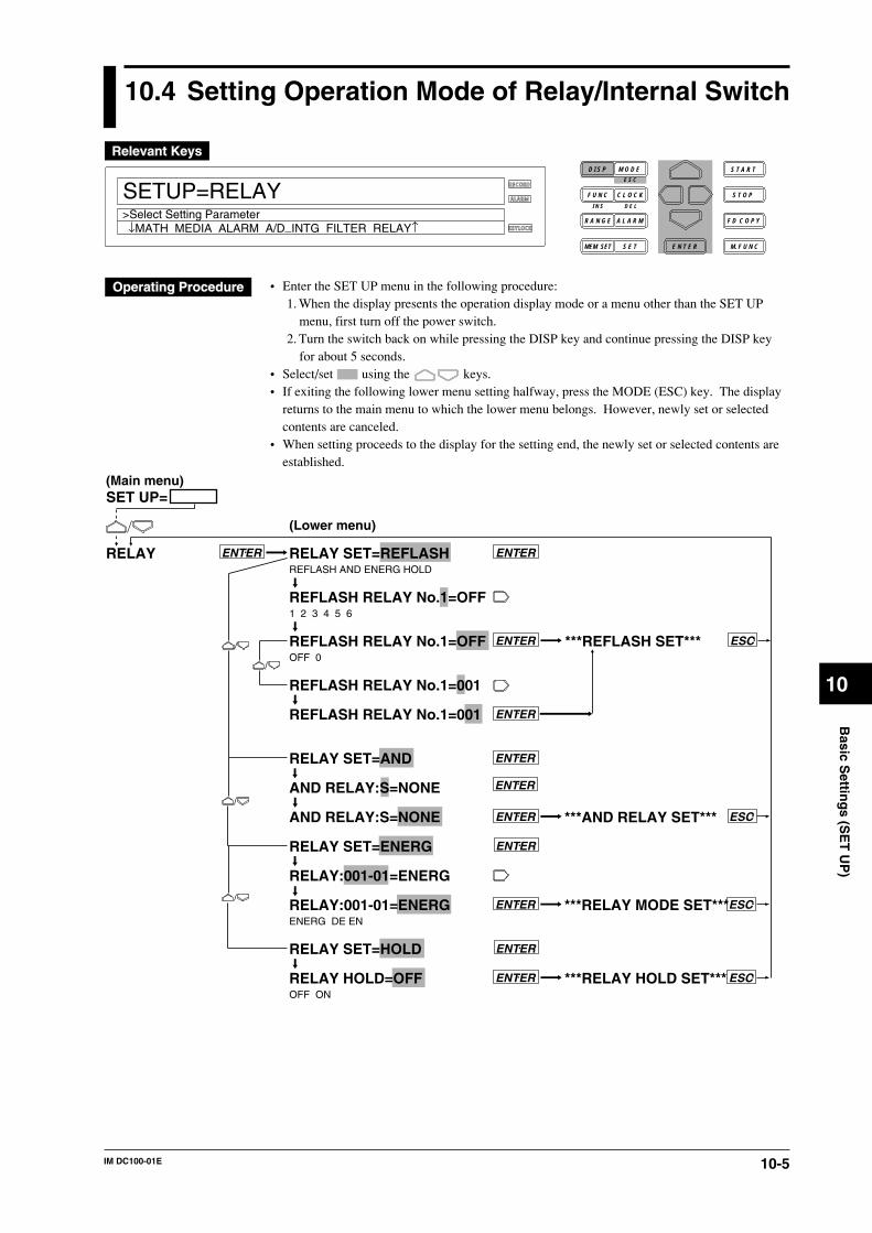
10-5IM DC100-01E
10
Basic S
etting
s (SE
T U
P)
10.4 Setting Operation Mode of Relay/Internal Switch
RECORD
ALARM
KEYLOCK
SETUP=RELAY
↓MATH MEDIA ALARM A/D_INTG FILTER RELAY↑>Select Setting Parameter
D I S P M O D E
C L O C KF U N C
I N S D E L
R A N G E A L A R M
S E TMEM SET E N T E R
S T O P
F D C O P Y
M. F U N C
S T A R TE S C
• Enter the SET UP menu in the following procedure:1. When the display presents the operation display mode or a menu other than the SET UP
menu, first turn off the power switch.2. Turn the switch back on while pressing the DISP key and continue pressing the DISP key
for about 5 seconds.• Select/set using the keys.• If exiting the following lower menu setting halfway, press the MODE (ESC) key. The display
returns to the main menu to which the lower menu belongs. However, newly set or selectedcontents are canceled.
• When setting proceeds to the display for the setting end, the newly set or selected contents areestablished.
RELAY SET=REFLASHREFLASH AND ENERG HOLD
REFLASH RELAY No.1=OFF1 2 3 4 5 6
REFLASH RELAY No.1=OFFOFF 0
REFLASH RELAY No.1=001
REFLASH RELAY No.1=001
RELAY SET=AND
AND RELAY:S=NONE
AND RELAY:S=NONE
RELAY SET=ENERG
RELAY:001-01=ENERG
RELAY:001-01=ENERGENERG DE EN
RELAY SET=HOLD
RELAY HOLD=OFFOFF ON
ENTERENTERRELAY
ESC
ENTER
ENTER
ENTER
***REFLASH SET***ENTER
***AND RELAY SET*** ESCENTER
ENTER
***RELAY MODE SET***ENTER ESC
ENTER
***RELAY HOLD SET***ENTER ESC
SET UP=(Main menu)
(Lower menu)
10-6 IM DC100-01E
The following operation mode is set to the alarm output relays and the internal switches. Thereare menus which cannot be displayed unless the alarm module or the DI/DO module is mountedand recognized as the system of this instrument. Also, there are menus which cannot be set to theinternal switches.Setting Re-failure or Re-alarm (REFLASH)This is a menu which cannot be displayed unless the alarm module or the DI/DO module ismounted and recognized as the system of this instrument. Setting for the internal switches cannotbe done. REFLASH setting is available for up to six relays.• Selection of REFLASH number (REFLASH RELAY No.)
Select from 1 to 6.• Setting of REFLASH relay
• OFF: not set.• Setting with numerals for 3 characters:
• The first character is the unit number.• For the second and third characters, a number from 01 to 60 can be set but the effective
setting range is as shown in the following examples: (Check which slot the alarm moduleor the DI/DO module is mounted in using the model number of mounted modules and theirmounted positions. Slot numbers are set in the order of slot 0, slot 1, ..... as viewed facingthe rear from right to left.)Ex. 1: When the alarm module is mounted in slot 3: 31 to 40Ex. 2: The DI/DO module is mounted in slot 4: 41 to 42
• The default setting is OFF.• After REFLASH setting, when the alarm module or the DI/DO module becomes
unrecognized as the system of this instrument, the relay setting becomes OFF.
Setting AND/OR (AND)This can be set either to the relays or the internal switches. However, the relay cannot be setunless the alarm module or DI/DO module is mounted and recognized as the system of thisinstrument.• Selection of Internal Switch/Relay
• S: internal switch is set.• I, 0 to 5: relay is set. For the stand-alone model, setting values other than 0 cannot be
selected.• The default setting is S.
• Setting AND/ORThe relays or the internal switches are set to AND in up to the set range and set to OR in therange exceeding the set range.• For internal switches: set from 01-01 to 01-60.• For one alarm module: 01-01 to 01-60 can be displayed. However, if this option is installed
in slot 4, 01-41 to 01-50 is the effective setting range.• For one DI/DO module: 01-01 to 01-60 can be displayed. However, if this option is
installed in slot 5, 01-51 to 01-52 is the effective setting range.• For two alarm modules: 01-01 to 01-60 can be displayed. However, if one module is
installed in slot 3 and another is installed in slot 5, 01-31 to 01-60 is the effective settingrange. No relay is in the range from 01-41 to 01-50.
• In either case above, if all are to be set to OR or reset, set “NONE.”• The default setting is NONE.
10.4 Setting Operation Mode of Relay/Internal Switch
10-7IM DC100-01E
10
Basic S
etting
s (SE
T U
P)
10.4 Setting Operation Mode of Relay/Internal Switch
Setting Energizing/De-energizing (ENERG)This is a menu which cannot be displayed unless the alarm module or the DI/DO module ismounted and recognized as the system of this instrument. The internal switches cannot be set.• Relay Setting
Set the object relays from one number relay (first relay) to another number relay (end relay).Set it under the condition that the first relay number ≤ end relay number.• First relay number:
• The first character is a unit number.• For the second and third characters, a number from 01 to 60 can be set but the effective
setting range is as shown in the following examples: (Check which slot the alarm moduleor the DI/DO module is mounted in using the model number of mounted modules and theirmounted positions. Slot numbers are set in the order of slot 0, slot 1, ..... as viewed facingthe rear from right to left.)Ex. 1: When the alarm module is mounted in slot 3: 31 to 40Ex. 2: The DI/DO module is mounted in slot 4: 41 to 42
• End relay number: The same settings of the second or third characters in the first relaynumber.
• The default setting is 001-01.• Selection of energizing/de-energizing
• ENERG: energizing• DE EN: de-energizing• The default setting is ENERG.
Setting Relay Hold (HOLD)This is a menu which cannot be displayed unless the alarm module or the DI/DO module ismounted and recognized as the system of this instrument. However, the internal switches are setsimultaneously with relays.• OFF: No relays/internal switches hold.• ON: all relays/internal switches hold.• The default setting is OFF.
Note• In order to make the set or selected contents effective, the contents must be registered. For details, see
page 10-20.• To return from the SET UP menu to the operation display mode, select END in the main menu. For
details, see page 10-20.
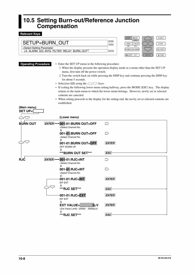
10-8 IM DC100-01E
10.5 Setting Burn-out/Reference JunctionCompensation
RECORD
ALARM
KEYLOCK
SETUP=BURN_OUT
↓A ALARM A/D_INTG FILTER RELAY BURN_OUT↑>Select Setting Parameter
D I S P M O D E
C L O C KF U N C
I N S D E L
R A N G E A L A R M
S E TMEM SET E N T E R
S T O P
F D C O P Y
M. F U N C
S T A R TE S C
• Enter the SET UP menu in the following procedure:1. When the display presents the operation display mode or a menu other than the SET UP
menu, first turn off the power switch.2. Turn the switch back on while pressing the DISP key and continue pressing the DISP key
for about 5 seconds.• Select/set using the keys.• If exiting the following lower menu setting halfway, press the MODE (ESC) key. The display
returns to the main menu to which the lower menu belongs. However, newly set or selectedcontents are canceled.
• When setting proceeds to the display for the setting end, the newly set or selected contents areestablished.
ENTER
ENTER
ESC
BURN OUT
RJC
ENTER
ENTER
ESC
ENTER
ESC
ENTER
001-01:BURN OUT=OFF>Select Channel No.
001-01:BURN OUT=OFF>Select Channel No.
001-01:BURN OUT=OFFOFF DOWN UP
***BURN OUT SET***
001-01:RJC=INT>Select Channel No.
001-01:RJC=INT>Select Channel No.
001-01:RJC=INTINT EXT
***RJC SET***
001-01:RJC=EXTINT EXT
EXT VALUE=_ _ _ _ _0µV>Ext Value Limit(– 20000~ 20000µV)
***RJC SET***
(Main menu)
(Lower menu)
SET UP=
10-9IM DC100-01E
10
Basic S
etting
s (SE
T U
P)
10.5 Setting Burn-out/Reference Junction Compensation
Setting Burn-out (BURN OUT)Set the overtravel position for each channel when burn-out occurs.• OFF: The burn-out function is not actuated.• DOWN: The output extends to the minimum value of the span.• UP: The output extends to the maximum value of the span.• The default setting is OFF.Setting Reference Junction Compensation (RJC)Set either the internal or the external compensation for each channel.• INT: internal compensation is performed.• EXT: external compensation is performed. For external compensation, set the voltage to be
compensated.Voltage to be externally compensated: set in the range of -20000 to 20000 µV.
• The default setting is INT.
Note• In order to make the set or selected contents effective, the contents must be registered. For details, see
page 10-20.• To return from the SET UP menu to the operation display mode, select END in the main menu. For
details, see page 10-20.
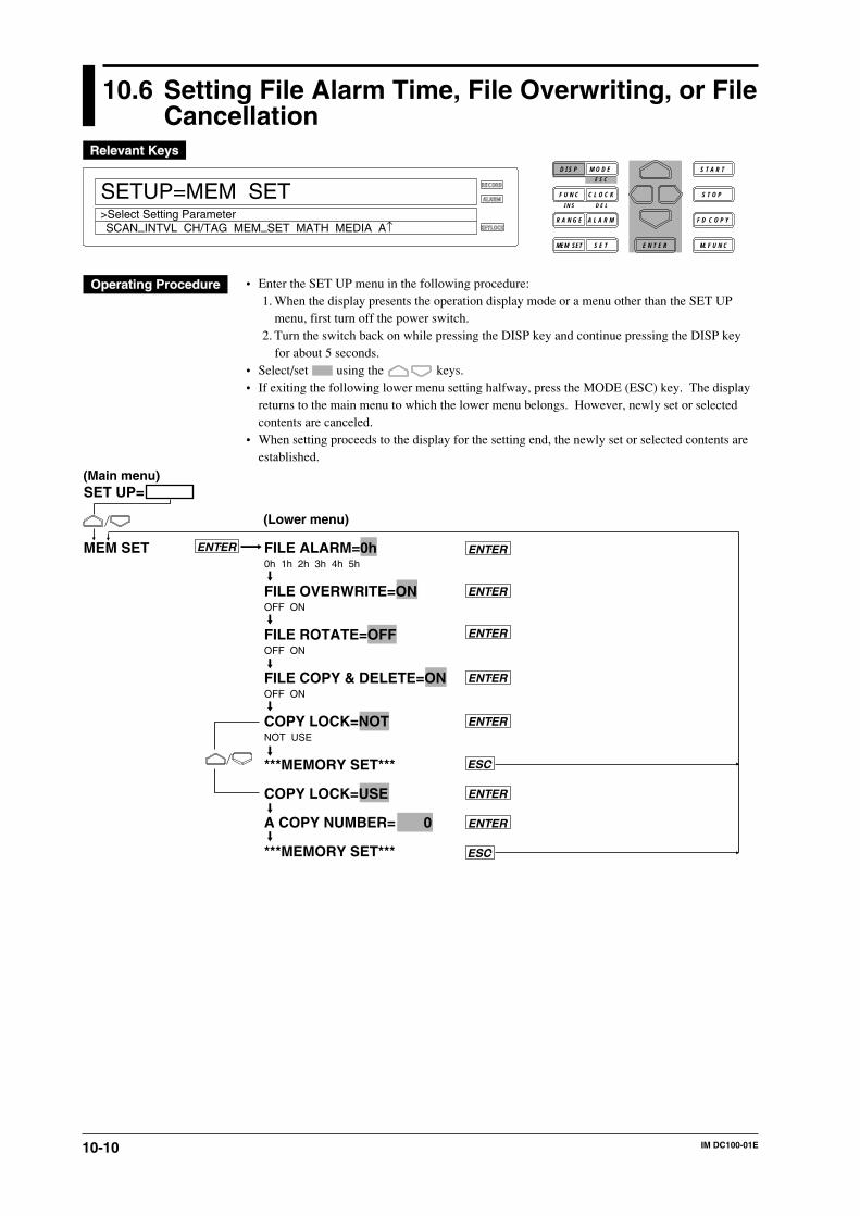
10-10 IM DC100-01E
10.6 Setting File Alarm Time, File Overwriting, or FileCancellation
RECORD
ALARM
KEYLOCK
SETUP=MEM SET
SCAN_INTVL CH/TAG MEM_SET MATH MEDIA A↑>Select Setting Parameter
D I S P M O D E
C L O C KF U N C
I N S D E L
R A N G E A L A R M
S E TMEM SET E N T E R
S T O P
F D C O P Y
M. F U N C
S T A R TE S C
• Enter the SET UP menu in the following procedure:1. When the display presents the operation display mode or a menu other than the SET UP
menu, first turn off the power switch.2. Turn the switch back on while pressing the DISP key and continue pressing the DISP key
for about 5 seconds.• Select/set using the keys.• If exiting the following lower menu setting halfway, press the MODE (ESC) key. The display
returns to the main menu to which the lower menu belongs. However, newly set or selectedcontents are canceled.
• When setting proceeds to the display for the setting end, the newly set or selected contents areestablished.
ENTER
ENTER
ENTER
ENTER
ENTER
ENTER
ENTER
ENTER
ESC
ESC
MEM SET FILE ALARM=0h0h 1h 2h 3h 4h 5h
FILE OVERWRITE=ONOFF ON
FILE ROTATE=OFFOFF ON
FILE COPY & DELETE=ONOFF ON
COPY LOCK=NOTNOT USE
***MEMORY SET***
COPY LOCK=USE
A COPY NUMBER= 0
***MEMORY SET***
(Main menu)
(Lower menu)
SET UP=
10-11IM DC100-01E
10
Basic S
etting
s (SE
T U
P)
Setting the File Alarm Time (FILE ALARM)• This outputs a file alarm from a relay when the remaining file capacity becomes below the one
corresponding to the specified time while the measured/computed data are being written in thebuilt-in RAM disk. Select the remaining time from the following:0h: Outputs an alarm when file has been created (file is closed).1h, 2h, 3h, 4h, or 5h: Outputs an alarm when the remaining time reaches the specified time.
• The default setting is “1h.”Overwriting a File with the Same Name (FILE OVERWRITE)• When measured/computed data are written, if there is a file with the same name in the built-in
RAM disk, set whether to overwrite the file or not.ON: Overwrites the file.OFF: Stops writing.
Continuing of saving operation when saving with division method (FILE ROTATE)• If saving with the division method and the saving operation is REPEAT, and if memory
becomes full and so there is no file creation capacity, the saving operation is continued bydeleting the file with the oldest date and time.ON: Continues saving operation by deleting a file.OFF: Terminates the saving operation.
• The default setting is OFF.File Deletion When Copying a File (FILE COPY & DELETE)• Set whether a file in the copying source is to be deleted or not when copying a measured/
computed data file to a floppy disk.ON: Delete.OFF: Do not delete.
• The default setting is OFF.• ASCII-converted copying is not supported.Selecting Use or Nonuse of Copy Lock (COPY LOCK)• Whether the lock function is used or not is set when measured/computed data are to be copied
on a floppy disk.NOT: Not used.USE: Used.
• The default setting is NOT.• Copy lock supports both copying with the FD COPY key and with ASCII-conversion.Setting Password in Copy Locking (A COPY NUMBER)A password is set if copy locking is used.The default setting is “0.”
Note• In order to make the set or selected contents effective, the contents must be registered. For details, see
page 10-20.• To return from the SET UP menu to the operation display mode, select END in the main menu. For
details, see page 10-20.
10.6 Setting File Alarm Time, File Overwriting, or File Cancellation
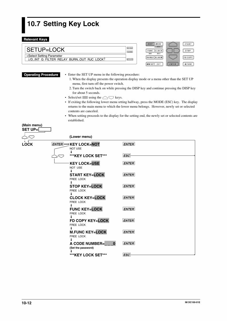
10-12 IM DC100-01E
10.7 Setting Key Lock
RECORD
ALARM
KEYLOCK
SETUP=LOCK
↓/D_INT G FILTER RELAY BURN_OUT RJC LOCK↑>Select Setting Parameter
D I S P M O D E
C L O C KF U N C
I N S D E L
R A N G E A L A R M
S E TMEM SET E N T E R
S T O P
F D C O P Y
M. F U N C
S T A R TE S C
• Enter the SET UP menu in the following procedure:1. When the display presents the operation display mode or a menu other than the SET UP
menu, first turn off the power switch.2. Turn the switch back on while pressing the DISP key and continue pressing the DISP key
for about 5 seconds.• Select/set using the keys.• If exiting the following lower menu srtting halfway, press the MODE (ESC) key. The display
returns to the main menu to which the lower menu belongs. However, newly set or selectedcontents are canceled.
• When setting proceeds to the display for the setting end, the newly set or selected contents areestablished.
KEY LOCK=NOTNOT USE
***KEY LOCK SET***
KEY LOCK=USENOT USE
START KEY=LOCKFREE LOCK
STOP KEY=LOCKFREE LOCK
CLOCK KEY=LOCKFREE LOCK
FUNC KEY=LOCKFREE LOCK
FD COPY KEY=LOCKFREE LOCK
M.FUNC KEY=LOCKFREE LOCK
A CODE NUMBER=_ _ _0(Set the password)
***KEY LOCK SET***
ENTER
ENTER
ENTER
LOCK
ENTER
ENTER
ESC
ENTER
ESC
ENTER
ENTER
ENTER
ENTER
(Main menu)
(Lower menu)
SET UP=
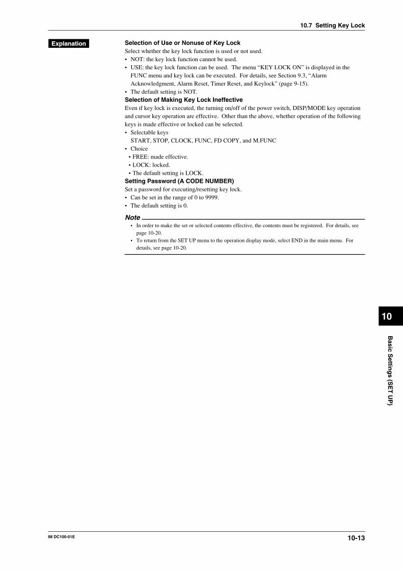
10-13IM DC100-01E
10
Basic S
etting
s (SE
T U
P)
Selection of Use or Nonuse of Key LockSelect whether the key lock function is used or not used.• NOT: the key lock function cannot be used.• USE: the key lock function can be used. The menu “KEY LOCK ON” is displayed in the
FUNC menu and key lock can be executed. For details, see Section 9.3, “AlarmAcknowledgment, Alarm Reset, Timer Reset, and Keylock” (page 9-15).
• The default setting is NOT.Selection of Making Key Lock IneffectiveEven if key lock is executed, the turning on/off of the power switch, DISP/MODE key operationand cursor key operation are effective. Other than the above, whether operation of the followingkeys is made effective or locked can be selected.• Selectable keys
START, STOP, CLOCK, FUNC, FD COPY, and M.FUNC• Choice
• FREE: made effective.• LOCK: locked.• The default setting is LOCK.
Setting Password (A CODE NUMBER)Set a password for executing/resetting key lock.• Can be set in the range of 0 to 9999.• The default setting is 0.
Note• In order to make the set or selected contents effective, the contents must be registered. For details, see
page 10-20.• To return from the SET UP menu to the operation display mode, select END in the main menu. For
details, see page 10-20.
10.7 Setting Key Lock

10-14 IM DC100-01E
10.8 Setting FUNC/FUNC3 Menu
RECORD
ALARM
KEYLOCK
SETUP=FUNC_PARM
↓LTER RELAY BURN_OUT RJC LOCK FUNC_PARM↑>Select Setting Parameter
D I S P M O D E
C L O C KF U N C
I N S D E L
R A N G E A L A R M
S E TMEM SET E N T E R
S T O P
F D C O P Y
M. F U N C
S T A R TE S C
• Enter the SET UP menu in the following procedure:1. When the display presents the operation display mode or a menu other than the SET UP
menu, first turn off the power switch.2. Turn the switch back on while pressing the DISP key and continue pressing the DISP key
for about 5 seconds.• Select/set using the keys.• If exiting the following lower menu setting halfway, press the MODE (ESC) key. The display
returns to the main menu to which the lower menu belongs. However, newly set or selectedcontents are canceled.
• When setting proceeds to the display for the setting end, the newly set or selected contents areestablished.
ESC
ENTER
ENTER
ENTER
ENTER
To next page
FUNC PARM ENTER
***FUNC PARM SET***ENTER
ENTER
ENTER
ENTER
ENTER
ENTER
ENTER
ENTER
ENTER
ENTER
From the following page
(Main menu)
(Lower menu)
SET UP=
PANEL:DATA WRITE
DATA WRITE=FUNCFUNC FUNC3 OFF
PANEL:ALARM ACK
ALARM ACK=FUNCFUNC FUNC3 OFF
PANEL:ALARM RESET
ALARM RESET=FUNCFUNC FUNC3 OFF
PANEL:TIMER RESET
TIMER RESET=FUNCFUNC FUNC3 OFF
PANEL:MATH_START
MATH_START=FUNCFUNC FUNC3 OFF
PANEL:MATH_CLR_START
MATH_CLR_START=FUNCFUNC FUNC3 OFF
PANEL:MATH_STOP
MATH_STOP=FUNCFUNC FUNC3 OFF
10-15IM DC100-01E
10
Basic S
etting
s (SE
T U
P)
PANEL:MATH_ACK
MATH_ACK=FUNCFUNC FUNC3 OFF
PANEL:KEY LOCK ON
KEY LOCK ON=FUNCFUNC FUNC3 OFF
PANEL:KEY LOCK OFF
KEY LOCK OFF=FUNCFUNC FUNC3 OFF
PANEL:MODULE INF
MODULE INF=FUNC3FUNC FUNC3 OFF
PANEL:COMM INF
COMM INF=FUNC3FUNC FUN3 OFF
PANEL:RE SYSTEM
RE SYSTEM:FUNC3
PANEL:RAM INT
RAM INT=FUNC3FUNC FUNC3 OFF
PANEL:INIT BALANCE
INIT BALANCE:FUNC3FUNC FUNC3 OFF
PANEL:REPORT START
REPORT START=FUNC
PANEL:REPORT STOP
REPORT STOP=FUNC
PANEL:ALL ITEM
ALL ITEM=FUNCFUNC FUNC3 OFF INIT
ENTER
ENTER
ENTER
ENTER
ENTER
ENTER
ENTER
ENTER
ENTER
ENTER
ENTER
ENTER
ENTER
ENTER
ENTER
ENTER
ENTER
ENTER
ENTER
ENTER
ENTER
ENTER
From previous page To previous page
10.8 Setting FUNC/FUNC3 Menu
10-16 IM DC100-01E
Setting FUNC/FUNC3 (FUNC PARM)Select the menu to be displayed by pressing the FUNC key whether in the FUNC menu or theFUNC3 menu. The FUNC menu is displayed by pressing the FUNC key at a touch and theFUNC3 menu is displayed by pressing the FUNC key for about 3 seconds continuously.• Select any of the following:
• FUNC: displayed in the FUNC menu.• FUNC3: displayed in the FUNC3 menu.• OFF: not displayed in either menu.
• The default setting is as shown in the operating procedure diagram on pages 10-14 and 10-15.• The last operation menu, “PANEL:ALL ITEM” is the menu that globally sets all menus.
However, the selection of “INIT” selects the default setting.• The “COMM INF” menu is displayed if the communication module is mounted and recognized
as the system of this instrument (see page 9-17).• The “INIT BALANCE” menu is displayed if the strain input module is mounted and
recognized as the system of this instrument (see page 9-17).
Note• In order to make the set or selected contents effective, the contents must be registered. For details, see
page 10-20.• To return from the SET UP menu to the operation display mode, select END in the main menu. For
details, see page 10-20.• Different menu items may be displayed depending upon the optional function(s) installed on the DC100
and the corresponding system configuration.
10.8 Setting FUNC/FUNC3 Menu
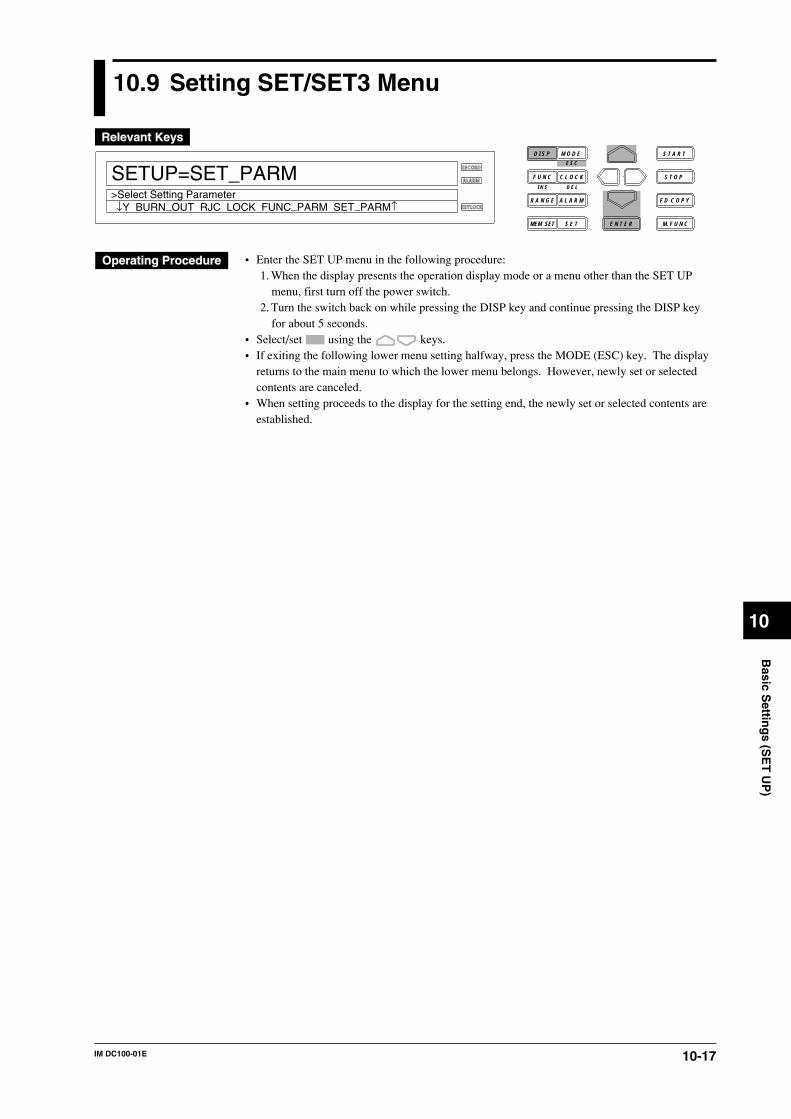
10-17IM DC100-01E
10
Basic S
etting
s (SE
T U
P)
10.9 Setting SET/SET3 Menu
RECORD
ALARM
KEYLOCK
SETUP=SET_PARM
↓Y BURN_OUT RJC LOCK FUNC_PARM SET_PARM↑>Select Setting Parameter
D I S P M O D E
C L O C KF U N C
I N S D E L
R A N G E A L A R M
S E TMEM SET E N T E R
S T O P
F D C O P Y
M. F U N C
S T A R TE S C
• Enter the SET UP menu in the following procedure:1. When the display presents the operation display mode or a menu other than the SET UP
menu, first turn off the power switch.2. Turn the switch back on while pressing the DISP key and continue pressing the DISP key
for about 5 seconds.• Select/set using the keys.• If exiting the following lower menu setting halfway, press the MODE (ESC) key. The display
returns to the main menu to which the lower menu belongs. However, newly set or selectedcontents are canceled.
• When setting proceeds to the display for the setting end, the newly set or selected contents areestablished.
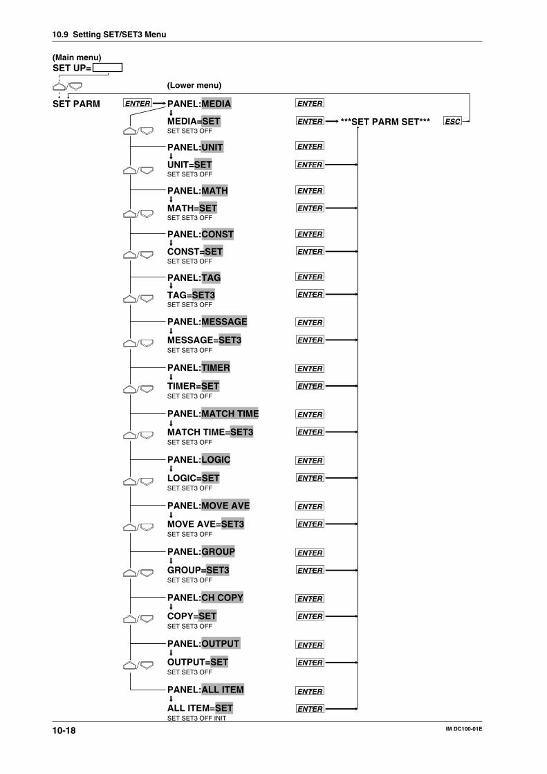
10-18 IM DC100-01E
PANEL:MEDIA
MEDIA=SETSET SET3 OFF
PANEL:UNIT
UNIT=SETSET SET3 OFF
PANEL:MATH
MATH=SETSET SET3 OFF
PANEL:CONST
CONST=SETSET SET3 OFF
PANEL:TAG
TAG=SET3SET SET3 OFF
PANEL:MESSAGE
MESSAGE=SET3SET SET3 OFF
PANEL:TIMER
TIMER=SETSET SET3 OFF
PANEL:MATCH TIME
MATCH TIME=SET3SET SET3 OFF
PANEL:LOGIC
LOGIC=SETSET SET3 OFF
PANEL:MOVE AVE
MOVE AVE=SET3SET SET3 OFF
PANEL:GROUP
GROUP=SET3SET SET3 OFF
PANEL:CH COPY
COPY=SETSET SET3 OFF
PANEL:OUTPUT
OUTPUT=SETSET SET3 OFF
PANEL:ALL ITEM
ALL ITEM=SETSET SET3 OFF INIT
ESC
ENTER
ENTER
ENTER
ENTERSET PARM
ENTER
ENTER
***SET PARM SET***ENTER
ENTER
ENTER
ENTER
ENTER
ENTER
ENTER
ENTER
ENTER
ENTER
ENTER
ENTER
ENTER
ENTER
ENTER
ENTER
ENTER
ENTER
ENTER
ENTER
ENTER
(Main menu)
(Lower menu)
SET UP=
ENTER
ENTER
10.9 Setting SET/SET3 Menu
10-19IM DC100-01E
10
Basic S
etting
s (SE
T U
P)
Setting SET/SET3 (SET PARM)Select the menu to be displayed by pressing the SET key whether in the SET menu or the SET3menu. The SET menu is displayed by pressing the SET key at a touch and the SET3 menu isdisplayed by pressing the SET key for about 3 seconds continuously.• Select any of the following:
• SET: displayed in the SET menu.• SET3: displayed in the SET3 menu.• OFF: not displayed in either menu.
• The default setting is as shown in the operating procedure diagram on pages 10-18.• The last operation menu, “PANEL:ALL ITEM,” is the menu that globally sets all menus.
However, the selection of “INIT” selects the default setting.
Note• In order to make the set or selected contents effective, the contents must be registered. For details, see
page 10-20.• To return from the SET UP menu to the operation display mode, select END in the main menu. For
details, see page 10-20.• Different menu items may be displayed depending upon the optional function(s) installed on the DC100
and the corresponding system configuration.• To set the retransmission setting in SET/SET3 menu, select “SET’ or “SET3” in “OUTPUT.”
10.9 Setting SET/SET3 Menu
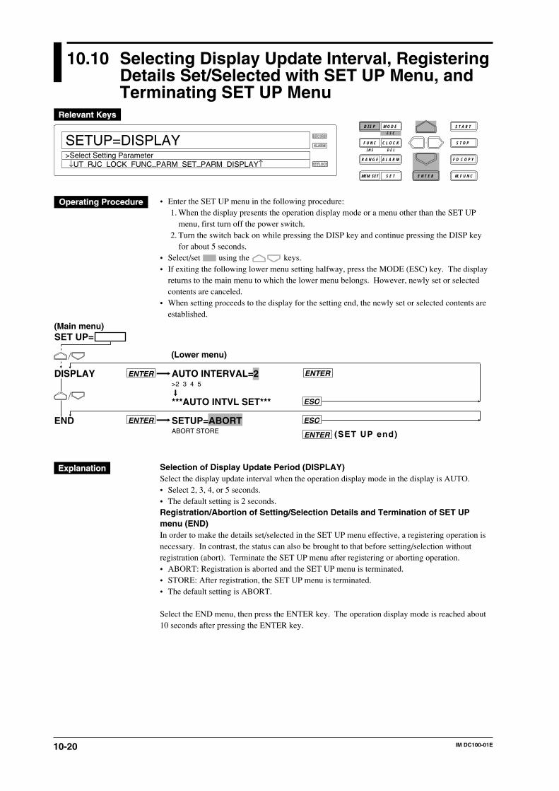
10-20 IM DC100-01E
10.10 Selecting Display Update Interval, RegisteringDetails Set/Selected with SET UP Menu, andTerminating SET UP Menu
RECORD
ALARM
KEYLOCK
SETUP=DISPLAY
↓UT RJC LOCK FUNC_PARM SET_PARM DISPLAY↑>Select Setting Parameter
D I S P M O D E
C L O C KF U N C
I N S D E L
R A N G E A L A R M
S E TMEM SET E N T E R
S T O P
F D C O P Y
M. F U N C
S T A R TE S C
• Enter the SET UP menu in the following procedure:1. When the display presents the operation display mode or a menu other than the SET UP
menu, first turn off the power switch.2. Turn the switch back on while pressing the DISP key and continue pressing the DISP key
for about 5 seconds.• Select/set using the keys.• If exiting the following lower menu setting halfway, press the MODE (ESC) key. The display
returns to the main menu to which the lower menu belongs. However, newly set or selectedcontents are canceled.
• When setting proceeds to the display for the setting end, the newly set or selected contents areestablished.
AUTO INTERVAL=2>2 3 4 5
***AUTO INTVL SET***
SETUP=ABORTABORT STORE
DISPLAY
END
ENTER
ESC
ENTER
ENTER
ESC
ENTER
(SET UP end)
(Main menu)
(Lower menu)
SET UP=
Selection of Display Update Period (DISPLAY)Select the display update interval when the operation display mode in the display is AUTO.• Select 2, 3, 4, or 5 seconds.• The default setting is 2 seconds.Registration/Abortion of Setting/Selection Details and Termination of SET UPmenu (END)In order to make the details set/selected in the SET UP menu effective, a registering operation isnecessary. In contrast, the status can also be brought to that before setting/selection withoutregistration (abort). Terminate the SET UP menu after registering or aborting operation.• ABORT: Registration is aborted and the SET UP menu is terminated.• STORE: After registration, the SET UP menu is terminated.• The default setting is ABORT.
Select the END menu, then press the ENTER key. The operation display mode is reached about10 seconds after pressing the ENTER key.
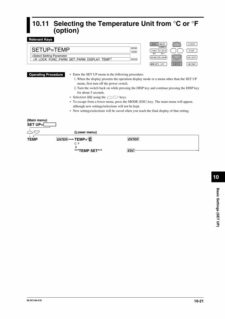
10-21IM DC100-01E
10
Basic S
etting
s (SE
T U
P)
10.11 Selecting the Temperature Unit from °C or °F(option)
RECORD
ALARM
KEYLOCK
SETUP=TEMP
↓R LOCK FUNC_PARM SET_PARM DISPLAY TEMP↑>Select Setting Parameter
D I S P M O D E
C L O C KF U N C
I N S D E L
R A N G E A L A R M
S E TMEM SET E N T E R
S T O P
F D C O P Y
M. F U N C
S T A R TE S C
• Enter the SET UP menu in the following procedure:1. When the display presents the operation display mode or a menu other than the SET UP
menu, first turn off the power switch.2. Turn the switch back on while pressing the DISP key and continue pressing the DISP key
for about 5 seconds.• Select/set using the keys.• To escape from a lower menu, press the MODE (ESC) key. The main menu will appear,
although new settings/selections will not be kept.• New settings/selections will be saved when you reach the final display of that setting.
TEMP=°CC F
***TEMP SET***
TEMP ENTER ENTER
ESC
(Main menu)
(Lower menu)
SET UP=
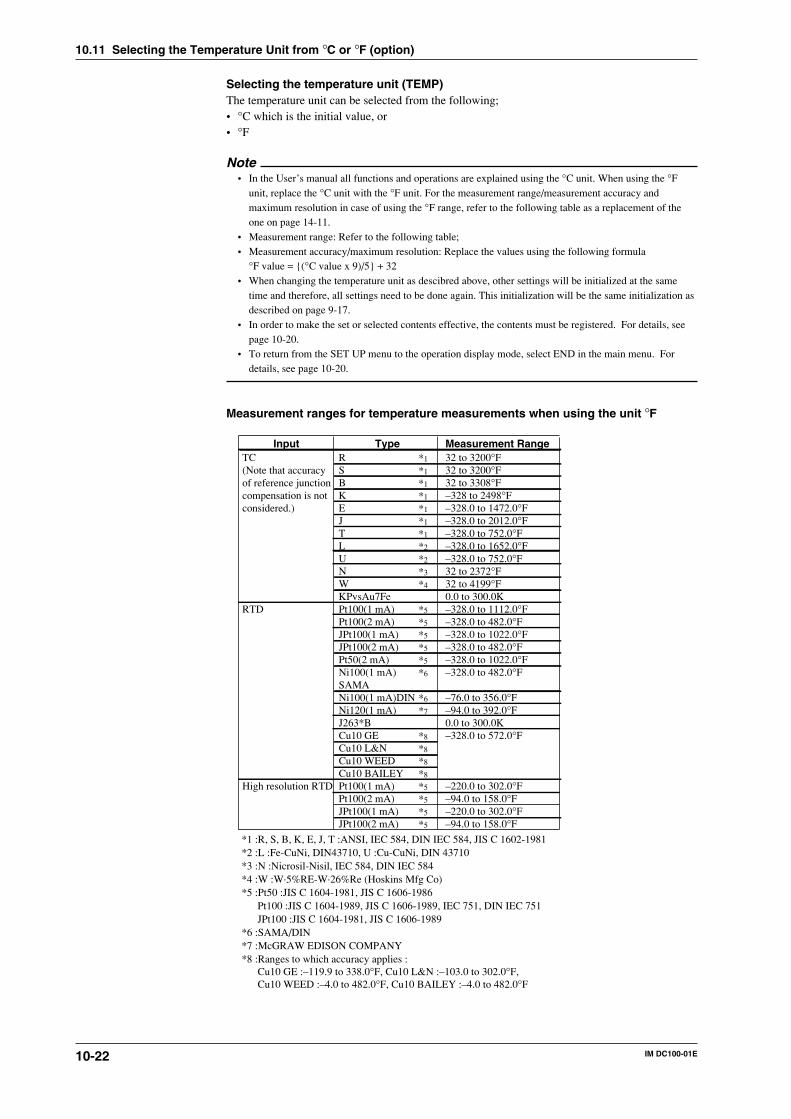
10-22 IM DC100-01E
Selecting the temperature unit (TEMP)The temperature unit can be selected from the following;• °C which is the initial value, or• °F
Note• In the User’s manual all functions and operations are explained using the °C unit. When using the °F
unit, replace the °C unit with the °F unit. For the measurement range/measurement accuracy andmaximum resolution in case of using the °F range, refer to the following table as a replacement of theone on page 14-11.
• Measurement range: Refer to the following table;• Measurement accuracy/maximum resolution: Replace the values using the following formula
°F value = (°C value x 9)/5 + 32• When changing the temperature unit as descibred above, other settings will be initialized at the same
time and therefore, all settings need to be done again. This initialization will be the same initialization asdescribed on page 9-17.
• In order to make the set or selected contents effective, the contents must be registered. For details, seepage 10-20.
• To return from the SET UP menu to the operation display mode, select END in the main menu. Fordetails, see page 10-20.
Measurement ranges for temperature measurements when using the unit °F
InputTC(Note that accuracyof reference junctioncompensation is not considered.)
RTD
High resolution RTD
RSBKEJTLUNWKPvsAu7FePt100(1 mA)Pt100(2 mA)JPt100(1 mA)JPt100(2 mA)Pt50(2 mA)Ni100(1 mA)SAMANi100(1 mA)DINNi120(1 mA)J263*BCu10 GECu10 L&NCu10 WEEDCu10 BAILEYPt100(1 mA)Pt100(2 mA)JPt100(1 mA)JPt100(2 mA)
32 to 3200°F32 to 3200°F32 to 3308°F–328 to 2498°F–328.0 to 1472.0°F–328.0 to 2012.0°F–328.0 to 752.0°F–328.0 to 1652.0°F–328.0 to 752.0°F32 to 2372°F32 to 4199°F0.0 to 300.0K–328.0 to 1112.0°F–328.0 to 482.0°F–328.0 to 1022.0°F–328.0 to 482.0°F–328.0 to 1022.0°F–328.0 to 482.0°F
–76.0 to 356.0°F–94.0 to 392.0°F0.0 to 300.0K–328.0 to 572.0°F
–220.0 to 302.0°F–94.0 to 158.0°F–220.0 to 302.0°F–94.0 to 158.0°F
Type Measurement Range*1
*1
*1
*1
*1
*1
*1
*2
*2
*3
*4
*5
*5
*5
*5
*5
*6
*6
*7
*8
*8
*8
*8
*5
*5
*5
*5
*1 :R, S, B, K, E, J, T :ANSI, IEC 584, DIN IEC 584, JIS C 1602-1981*2 :L :Fe-CuNi, DIN43710, U :Cu-CuNi, DIN 43710*3 :N :Nicrosil-Nisil, IEC 584, DIN IEC 584*4 :W :W·5%RE-W·26%Re (Hoskins Mfg Co)*5 :Pt50 :JIS C 1604-1981, JIS C 1606-1986 Pt100 :JIS C 1604-1989, JIS C 1606-1989, IEC 751, DIN IEC 751 JPt100 :JIS C 1604-1981, JIS C 1606-1989*6 :SAMA/DIN*7 :McGRAW EDISON COMPANY*8 :Ranges to which accuracy applies : Cu10 GE :–119.9 to 338.0°F, Cu10 L&N :–103.0 to 302.0°F, Cu10 WEED :–4.0 to 482.0°F, Cu10 BAILEY :–4.0 to 482.0°F
10.11 Selecting the Temperature Unit from °C or °F (option)
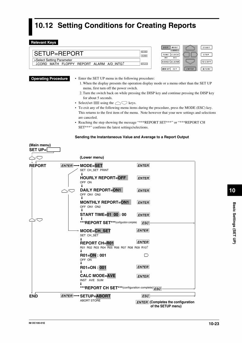
10-23IM DC100-01E
10
Basic S
etting
s (SE
T U
P)
10.12 Setting Conditions for Creating Reports
RECORD
ALARM
KEYLOCK
SETUP=REPORT
↓CORD MATH FLOPPY REPORT ALARM A/D_INTG↑>Select Setting Parameter
D I S P M O D E
C L O C KF U N C
I N S D E L
R A N G E A L A R M
S E TMEM SET E N T E R
S T O P
F D C O P Y
M. F U N C
S T A R TE S C
• Enter the SET UP menu in the following procedure:1. When the display presents the operation display mode or a menu other than the SET UP
menu, first turn off the power switch.2. Turn the switch back on while pressing the DISP key and continue pressing the DISP key
for about 5 seconds.• Select/set using the keys.• To exit any of the following menu items during the procedure, press the MODE (ESC) key.
This returns to the first item of the menu. Note however that your new settings and selectionsare canceled.
• Reaching the step showing the message “***REPORT SET***” or “***REPORT CHSET***” confirms the latest settings/selections.
Sending the Instantaneous Value and Average to a Report Output
MODE=SETSET CH_SET PRINT
HOURLY REPORT=OFFOFF ON
DAILY REPORT=ON1OFF ON1 ON2
MONTHLY REPORT=ON1OFF ON1 ON2
START TIME=01 00 : 00
***REPORT SET***(configuration complete)
MODE=CH_SETSET CH_SET
REPORT CH=R01R01 R02 R03 R04 R05 R06 R07 R08 R09 R10↑
R01=ON : 001OFF ON
R01=ON : 001
CALC MODE=AVEINST AVE SUM
***REPORT CH SET***(configuration complete)
SETUP=ABORTABORT STORE
REPORT
END
ENTER ENTER
(Main menu)
(Lower menu)
SET UP=
ENTER
ENTER
ENTER
ENTER
ESC
ENTER
ENTER
ENTER
(Completes the configuration of the SETUP menu)
ENTER
ENTER
ENTER
ESC
ESC
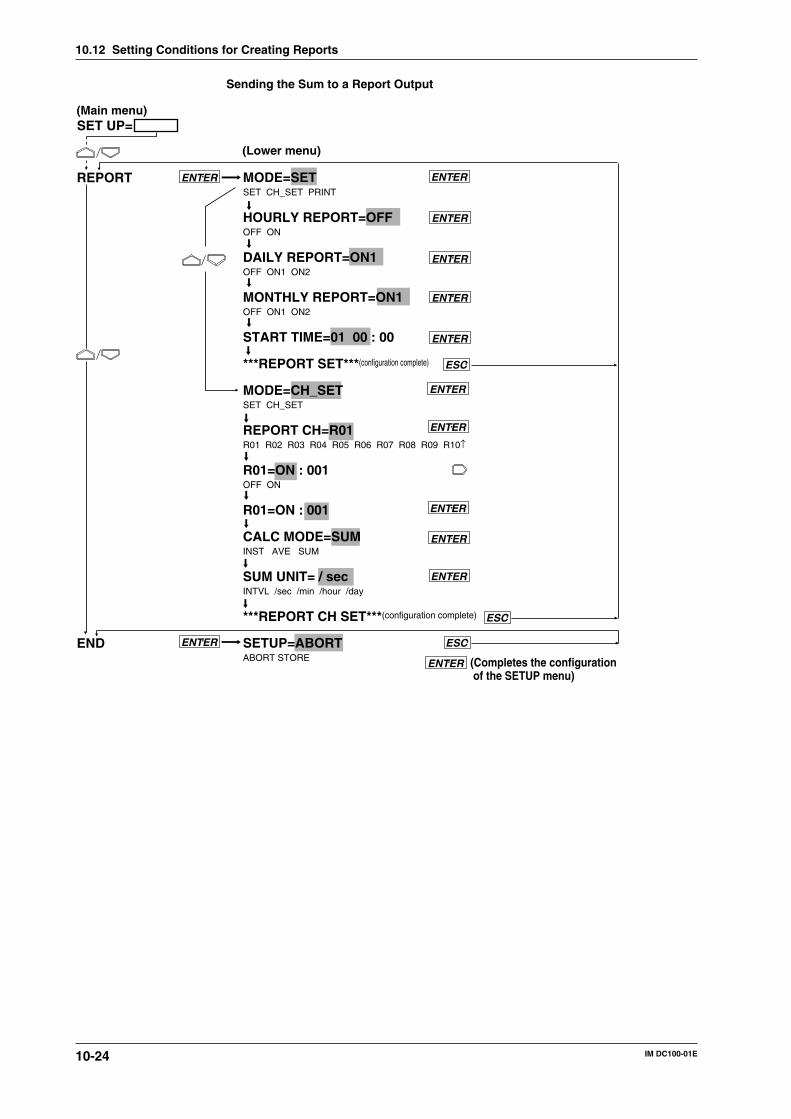
10-24 IM DC100-01E
10.12 Setting Conditions for Creating Reports
Sending the Sum to a Report Output
MODE=SETSET CH_SET PRINT
HOURLY REPORT=OFFOFF ON
DAILY REPORT=ON1OFF ON1 ON2
MONTHLY REPORT=ON1OFF ON1 ON2
START TIME=01 00 : 00
***REPORT SET***(configuration complete)
MODE=CH_SETSET CH_SET
REPORT CH=R01R01 R02 R03 R04 R05 R06 R07 R08 R09 R10↑
R01=ON : 001OFF ON
R01=ON : 001
CALC MODE=SUMINST AVE SUM
SUM UNIT= / secINTVL /sec /min /hour /day
***REPORT CH SET***(configuration complete)
SETUP=ABORTABORT STORE
REPORT
END
ENTER ENTER
(Main menu)
(Lower menu)
SET UP=
ENTER
ENTER
ENTER
ENTER
ESC
ENTER
ENTER
ENTER
(Completes the configuration of the SETUP menu)
ENTER
ENTER
ENTER
ESC
ESC
ENTER
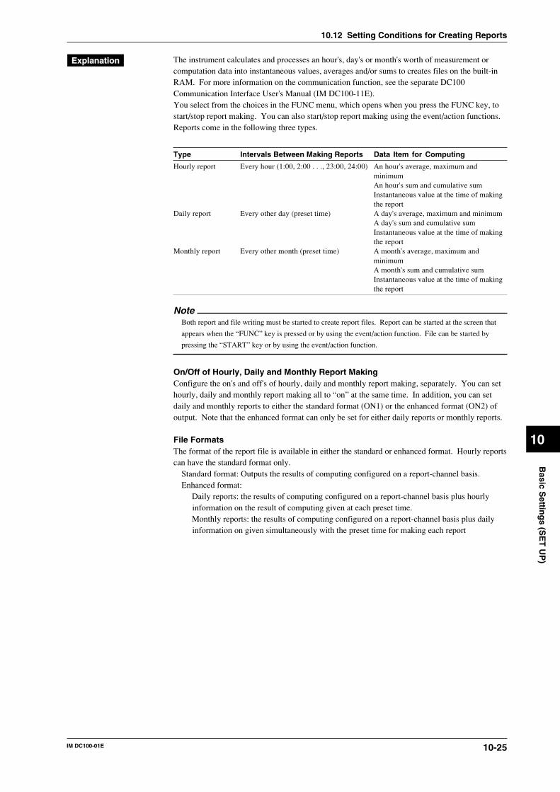
10-25IM DC100-01E
10
Basic S
etting
s (SE
T U
P)
The instrument calculates and processes an hour's, day's or month's worth of measurement orcomputation data into instantaneous values, averages and/or sums to creates files on the built-inRAM. For more information on the communication function, see the separate DC100Communication Interface User's Manual (IM DC100-11E).You select from the choices in the FUNC menu, which opens when you press the FUNC key, tostart/stop report making. You can also start/stop report making using the event/action functions.Reports come in the following three types.
Type Intervals Between Making Reports Data Item for Computing
Hourly report Every hour (1:00, 2:00 . . ., 23:00, 24:00) An hour's average, maximum andminimumAn hour's sum and cumulative sumInstantaneous value at the time of makingthe report
Daily report Every other day (preset time) A day's average, maximum and minimumA day's sum and cumulative sumInstantaneous value at the time of makingthe report
Monthly report Every other month (preset time) A month's average, maximum andminimumA month's sum and cumulative sumInstantaneous value at the time of makingthe report
NoteBoth report and file writing must be started to create report files. Report can be started at the screen that
appears when the “FUNC” key is pressed or by using the event/action function. File can be started by
pressing the “START” key or by using the event/action function.
On/Off of Hourly, Daily and Monthly Report MakingConfigure the on's and off's of hourly, daily and monthly report making, separately. You can sethourly, daily and monthly report making all to “on” at the same time. In addition, you can setdaily and monthly reports to either the standard format (ON1) or the enhanced format (ON2) ofoutput. Note that the enhanced format can only be set for either daily reports or monthly reports.
File FormatsThe format of the report file is available in either the standard or enhanced format. Hourly reportscan have the standard format only.
Standard format: Outputs the results of computing configured on a report-channel basis.Enhanced format:
Daily reports: the results of computing configured on a report-channel basis plus hourlyinformation on the result of computing given at each preset time.Monthly reports: the results of computing configured on a report-channel basis plus dailyinformation on given simultaneously with the preset time for making each report
10.12 Setting Conditions for Creating Reports
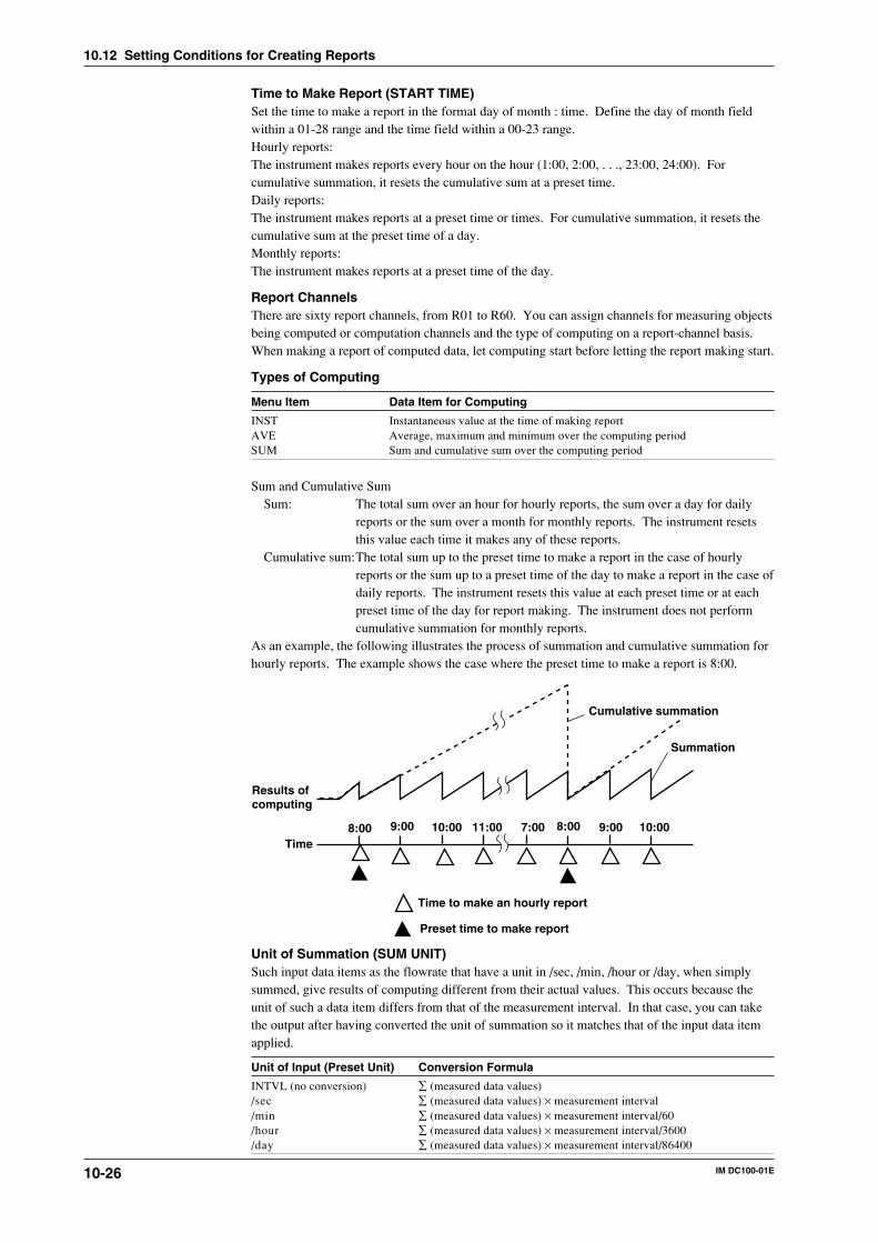
10-26 IM DC100-01E
Time to Make Report (START TIME)Set the time to make a report in the format day of month : time. Define the day of month fieldwithin a 01-28 range and the time field within a 00-23 range.Hourly reports:The instrument makes reports every hour on the hour (1:00, 2:00, . . ., 23:00, 24:00). Forcumulative summation, it resets the cumulative sum at a preset time.Daily reports:The instrument makes reports at a preset time or times. For cumulative summation, it resets thecumulative sum at the preset time of a day.Monthly reports:The instrument makes reports at a preset time of the day.
Report ChannelsThere are sixty report channels, from R01 to R60. You can assign channels for measuring objectsbeing computed or computation channels and the type of computing on a report-channel basis.When making a report of computed data, let computing start before letting the report making start.
Types of Computing
Menu Item Data Item for Computing
INST Instantaneous value at the time of making reportAVE Average, maximum and minimum over the computing periodSUM Sum and cumulative sum over the computing period
Sum and Cumulative SumSum: The total sum over an hour for hourly reports, the sum over a day for daily
reports or the sum over a month for monthly reports. The instrument resetsthis value each time it makes any of these reports.
Cumulative sum:The total sum up to the preset time to make a report in the case of hourlyreports or the sum up to a preset time of the day to make a report in the case ofdaily reports. The instrument resets this value at each preset time or at eachpreset time of the day for report making. The instrument does not performcumulative summation for monthly reports.
As an example, the following illustrates the process of summation and cumulative summation forhourly reports. The example shows the case where the preset time to make a report is 8:00.
9:00 11:00
Results ofcomputing
Time to make an hourly report
Time7:0010:008:00 8:00 9:00 10:00
Cumulative summation
Summation
Preset time to make report
Unit of Summation (SUM UNIT)Such input data items as the flowrate that have a unit in /sec, /min, /hour or /day, when simplysummed, give results of computing different from their actual values. This occurs because theunit of such a data item differs from that of the measurement interval. In that case, you can takethe output after having converted the unit of summation so it matches that of the input data itemapplied.
Unit of Input (Preset Unit) Conversion Formula
INTVL (no conversion) ∑ (measured data values)/sec ∑ (measured data values) × measurement interval/min ∑ (measured data values) × measurement interval/60/hour ∑ (measured data values) × measurement interval/3600/day ∑ (measured data values) × measurement interval/86400
10.12 Setting Conditions for Creating Reports
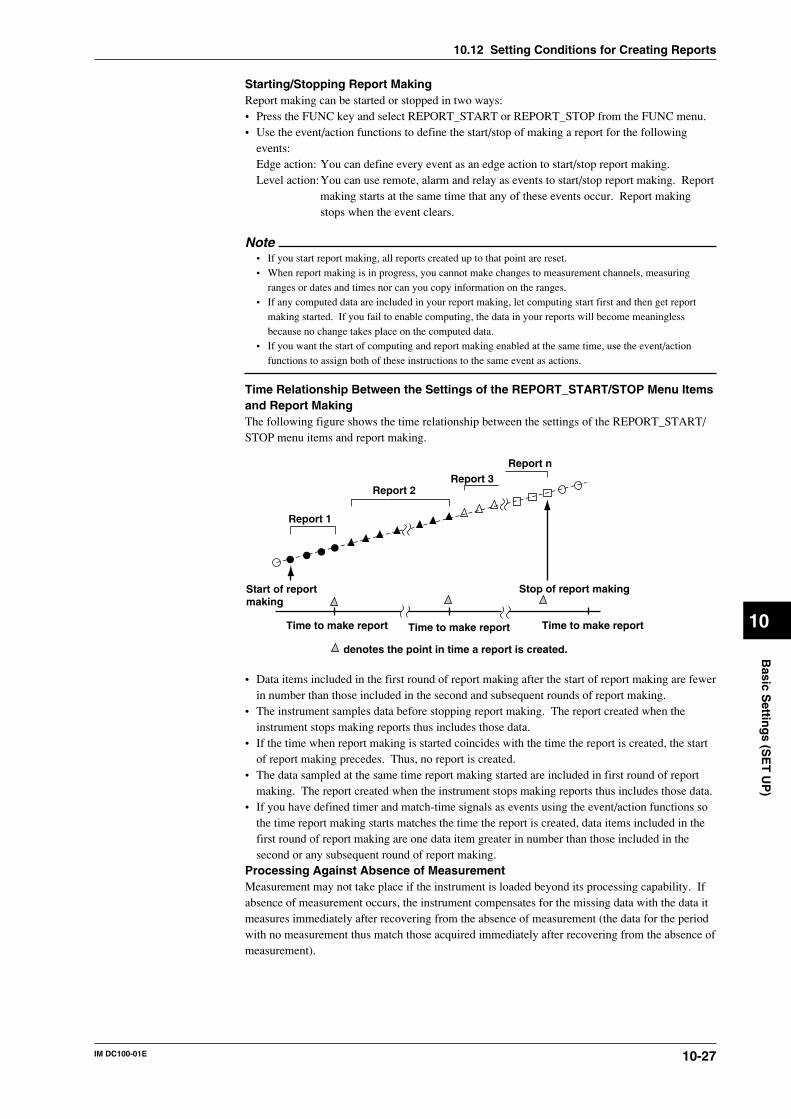
10-27IM DC100-01E
10
Basic S
etting
s (SE
T U
P)
Starting/Stopping Report MakingReport making can be started or stopped in two ways:• Press the FUNC key and select REPORT_START or REPORT_STOP from the FUNC menu.• Use the event/action functions to define the start/stop of making a report for the following
events:Edge action: You can define every event as an edge action to start/stop report making.Level action:You can use remote, alarm and relay as events to start/stop report making. Report
making starts at the same time that any of these events occur. Report makingstops when the event clears.
Note• If you start report making, all reports created up to that point are reset.• When report making is in progress, you cannot make changes to measurement channels, measuring
ranges or dates and times nor can you copy information on the ranges.• If any computed data are included in your report making, let computing start first and then get report
making started. If you fail to enable computing, the data in your reports will become meaninglessbecause no change takes place on the computed data.
• If you want the start of computing and report making enabled at the same time, use the event/actionfunctions to assign both of these instructions to the same event as actions.
Time Relationship Between the Settings of the REPORT_START/STOP Menu Itemsand Report MakingThe following figure shows the time relationship between the settings of the REPORT_START/STOP menu items and report making.
Report 1
Report 2Report 3
Report n
Start of reportmaking
denotes the point in time a report is created.
Time to make report Time to make report Time to make report
Stop of report making
• Data items included in the first round of report making after the start of report making are fewerin number than those included in the second and subsequent rounds of report making.
• The instrument samples data before stopping report making. The report created when theinstrument stops making reports thus includes those data.
• If the time when report making is started coincides with the time the report is created, the startof report making precedes. Thus, no report is created.
• The data sampled at the same time report making started are included in first round of reportmaking. The report created when the instrument stops making reports thus includes those data.
• If you have defined timer and match-time signals as events using the event/action functions sothe time report making starts matches the time the report is created, data items included in thefirst round of report making are one data item greater in number than those included in thesecond or any subsequent round of report making.
Processing Against Absence of MeasurementMeasurement may not take place if the instrument is loaded beyond its processing capability. Ifabsence of measurement occurs, the instrument compensates for the missing data with the data itmeasures immediately after recovering from the absence of measurement (the data for the periodwith no measurement thus match those acquired immediately after recovering from the absence ofmeasurement).
10.12 Setting Conditions for Creating Reports
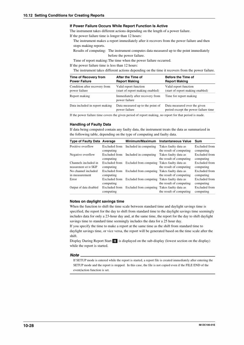
10-28 IM DC100-01E
If Power Failure Occurs While Report Function Is ActiveThe instrument takes different actions depending on the length of a power failure.If the power failure time is longer than 12 hours:
The instrument makes a report immediately after it recovers from the power failure and thenstops making reports.Results of computing: The instrument computes data measured up to the point immediately
before the power failure.Time of report making:The time when the power failure occurred.
If the power failure time is less than 12 hours:The instrument takes different actions depending on the time it recovers from the power failure.
Time of Recovery from After the Time of Before the Time ofPower Failure Report Making Report Making
Condition after recovery from Valid report function Valid report functionpower failure (start of report making enabled) (start of report making enabled)
Report making Immediately after recovery from Time for report makingpower failure
Data included in report making Data measured up to the point of Data measured over the givenpower failure period except the power failure time
If the power failure time covers the given period of report making, no report for that period is made.
Handling of Faulty DataIf data being computed contain any faulty data, the instrument treats the data as summarized inthe following table, depending on the type of computing and faulty data.
Type of Faulty Data Average Minimum/Maximum Instantaneous Value Sum
Positive overflow Excluded from Included in computing Takes faulty data as Excluded fromcomputing the result of computing computing
Negative overflow Excluded from Included in computing Takes faulty data as Excluded fromcomputing the result of computing computing
Channels included in Excluded from Excluded from computing Takes faulty data as Excluded frommeasurement set to SKIP computing the result of computing computingNo channel included Excluded from Excluded from computing Takes faulty data as Excluded fromin measurement computing the result of computing computingError Excluded from Excluded from computing Takes faulty data as Excluded from
computing the result of computing computingOutput of data disabled Excluded from Excluded from computing Takes faulty data as Excluded from
computing the result of computing computing
Notes on daylight savings timeWhen the function to shift the time scale between standard time and daylight savings time isspecified, the report for the day to shift from standard time to the daylight savings time seeminglyincludes data for only a 23-hour day and, at the same time, the report for the day to shift daylightsavings time to standard time seemingly includes the data for a 25 hour day.If you specify the time to make a report at the same time as the shift from standard time todaylight savings time, or vice versa, the report will be generated based on the time scale after theshift.Display During Report Start H is displayed on the sub-display (lowest section on the display)while the report is started.
NoteIf SETUP mode is entered while the report is started, a report file is created immediately after entering the
SETUP mode and the report is stopped. In this case, the file is not copied even if the FILE END of the
event/action function is set.
10.12 Setting Conditions for Creating Reports
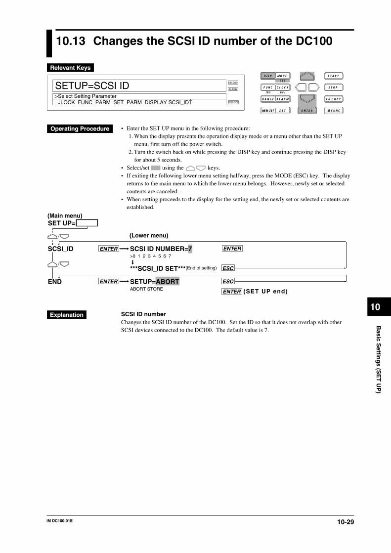
10-29IM DC100-01E
10
Basic S
etting
s (SE
T U
P)
10.13 Changes the SCSI ID number of the DC100
RECORD
ALARM
KEYLOCK
SETUP=SCSI ID
↓LOCK FUNC_PARM SET_PARM DISPLAY SCSI_ID↑>Select Setting Parameter
D I S P M O D E
C L O C KF U N C
I N S D E L
R A N G E A L A R M
S E TMEM SET E N T E R
S T O P
F D C O P Y
M. F U N C
S T A R TE S C
• Enter the SET UP menu in the following procedure:1. When the display presents the operation display mode or a menu other than the SET UP
menu, first turn off the power switch.2. Turn the switch back on while pressing the DISP key and continue pressing the DISP key
for about 5 seconds.• Select/set using the keys.• If exiting the following lower menu setting halfway, press the MODE (ESC) key. The display
returns to the main menu to which the lower menu belongs. However, newly set or selectedcontents are canceled.
• When setting proceeds to the display for the setting end, the newly set or selected contents areestablished.
SCSI ID NUMBER=7>0 1 2 3 4 5 6 7
***SCSI_ID SET***(End of setting)
SETUP=ABORTABORT STORE
SCSI_ID
END
ENTER
ESC
ENTER
ENTER
ESC
ENTER
SET UP=(Main menu)
(Lower menu)
(SET UP end)
SCSI ID numberChanges the SCSI ID number of the DC100. Set the ID so that it does not overlap with otherSCSI devices connected to the DC100. The default value is 7.
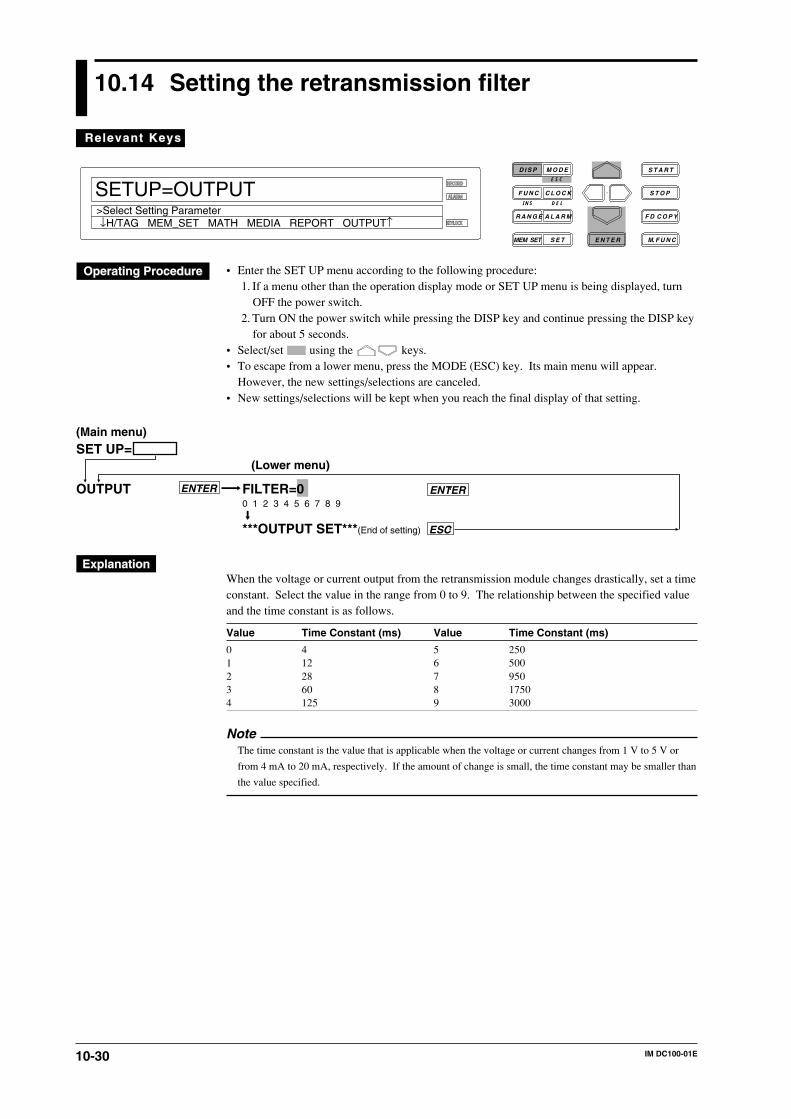
10-30 IM DC100-01E
10.14 Setting the retransmission filter
RECORD
ALARM
KEYLOCK
>Select Setting Parameter
D I S P M O D E
C L O C KF U N C
I N S D E L
R A N G E A L A R M
S E TMEM SET E N T E R
S T O P
F D C O P Y
M. F U N C
S T A R TE S C
SETUP=OUTPUT
↓H/TAG MEM_SET MATH MEDIA REPORT OUTPUT↑
Relevant KeysRelevant Keys
• Enter the SET UP menu according to the following procedure:1. If a menu other than the operation display mode or SET UP menu is being displayed, turn
OFF the power switch.2. Turn ON the power switch while pressing the DISP key and continue pressing the DISP key
for about 5 seconds.• Select/set using the keys.• To escape from a lower menu, press the MODE (ESC) key. Its main menu will appear.
However, the new settings/selections are canceled.• New settings/selections will be kept when you reach the final display of that setting.
SET UP=
OUTPUT FILTER=00 1 2 3 4 5 6 7 8 9
***OUTPUT SET***(End of setting)
ENTERENTER
ESC
(Main menu)
(Lower menu)
When the voltage or current output from the retransmission module changes drastically, set a timeconstant. Select the value in the range from 0 to 9. The relationship between the specified valueand the time constant is as follows.
Value Time Constant (ms) Value Time Constant (ms)
0 4 5 2501 12 6 5002 28 7 9503 60 8 17504 125 9 3000
NoteThe time constant is the value that is applicable when the voltage or current changes from 1 V to 5 V or
from 4 mA to 20 mA, respectively. If the amount of change is small, the time constant may be smaller than
the value specified.

11-1IM DC100-01E
Wo
rking
With
a File in
SE
T M
od
e or S
ET
UP
Mo
de
11
11.1 Saving Set-up Data
Saving set-up data for the SET mode
RECORD
ALARM
KEYLOCK
SET=MEDIA
MEDIA UNIT MATH CONST TIMER LOGIC CH_C↑>Select Setting Parameter
D I S P M O D E
C L O C KF U N C
I N S D E L
R A N G E A L A R M
S E TMEM SET E N T E R
S T O P
F D C O P Y
M. F U N C
S T A R TE S C
• Press the SET key to enter the SET menu.• Select/set using the keys.• To escape from a lower menu, press the MODE (ESC) key. Its main menu will appear,
although new settings/selections will not be kept.• New settings/selections will be kept when you reach the final display of that setting.
MEDIA=FLOPPY*1 ENTERFLOPPY SCSI IDENTIFY
FLOPPY=SAVE ENTERSAVE LOAD DIR DELETE INFO FORMAT
SAVE file= ENTER_____ AAA BBB CCC
SAVE FILE=AAA ENTER
Saving... *
***SAVE OK***(End of saving)
*1 Displayed when the SCSI option (/C5) is installed.
SET=
MEDIA ENTER
(Main menu)
(Lower menu)
SCSI is the SCSI ID number that is connected.
ESC
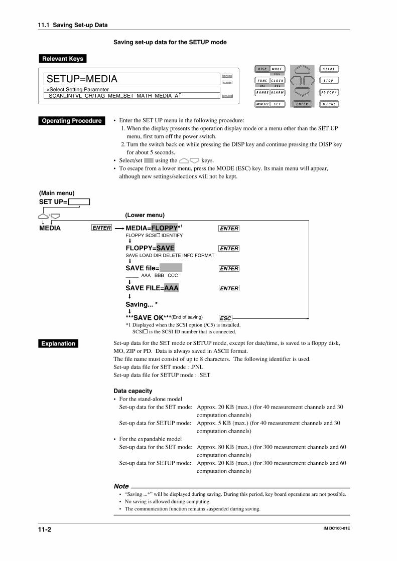
11-2 IM DC100-01E
Saving set-up data for the SETUP mode
RECORD
ALARM
KEYLOCK
SETUP=MEDIA
SCAN_INTVL CH/TAG MEM_SET MATH MEDIA A↑>Select Setting Parameter
D I S P M O D E
C L O C KF U N C
I N S D E L
R A N G E A L A R M
S E TMEM SET E N T E R
S T O P
F D C O P Y
M. F U N C
S T A R TE S C
• Enter the SET UP menu in the following procedure:1. When the display presents the operation display mode or a menu other than the SET UP
menu, first turn off the power switch.2. Turn the switch back on while pressing the DISP key and continue pressing the DISP key
for about 5 seconds.• Select/set using the keys.• To escape from a lower menu, press the MODE (ESC) key. Its main menu will appear,
although new settings/selections will not be kept.
SET UP=
MEDIA ENTER MEDIA=FLOPPY*1 ENTERFLOPPY SCSI IDENTIFY
FLOPPY=SAVE ENTERSAVE LOAD DIR DELETE INFO FORMAT
SAVE file= ENTER_____ AAA BBB CCC
SAVE FILE=AAA ENTER
Saving... *
***SAVE OK***(End of saving)
*1 Displayed when the SCSI option (/C5) is installed.
(Main menu)
(Lower menu)
SCSI is the SCSI ID number that is connected.
ESC
Set-up data for the SET mode or SETUP mode, except for date/time, is saved to a floppy disk,MO, ZIP or PD. Data is always saved in ASCII format.The file name must consist of up to 8 characters. The following identifier is used.Set-up data file for SET mode : .PNLSet-up data file for SETUP mode : .SET
Data capacity• For the stand-alone model
Set-up data for the SET mode: Approx. 20 KB (max.) (for 40 measurement channels and 30computation channels)
Set-up data for SETUP mode: Approx. 5 KB (max.) (for 40 measurement channels and 30computation channels)
• For the expandable modelSet-up data for the SET mode: Approx. 80 KB (max.) (for 300 measurement channels and 60
computation channels)Set-up data for SETUP mode: Approx. 20 KB (max.) (for 300 measurement channels and 60
computation channels)
Note• “Saving ...*” will be displayed during saving. During this period, key board operations are not possible.• No saving is allowed during computing.• The communication function remains suspended during saving.
11.1 Saving Set-up Data

11-3IM DC100-01E
Wo
rking
With
a File in
SE
T M
od
e or S
ET
UP
Mo
de
11
11.2 Reading Set-up Data
Reading set-up data for the SET mode
RECORD
ALARM
KEYLOCK
SET=MEDIA
MEDIA UNIT MATH CONST TIMER LOGIC CH_C↑>Select Setting Parameter
D I S P M O D E
C L O C KF U N C
I N S D E L
R A N G E A L A R M
S E TMEM SET E N T E R
S T O P
F D C O P Y
M. F U N C
S T A R TE S C
• Press the SET key to enter the SET menu.• Select/set using the keys.• To escape from a lower menu, press the MODE (ESC) key. Its main menu will appear,
although new settings/selections will not be kept.• New settings/selections will be kept when you reach the final display of that setting.
SET=
MEDIA ENTER MEDIA=FLOPPY*1 ENTERFLOPPY SCSI IDENTIFY
FLOPPY=LOAD ENTERSAVE LOAD DIR DELETE INFO FORMAT
LOAD MODE=DIRECT ENTERDIRECT TRIG_1 TRG_2 TRG_3
LOAD FILE=AAA ENTERAAA BBB CCC
Loading... *
Operation status displayed
*1 Displayed when the SCSI option (/C5) is installed.
(Main menu)
(Lower menu)
SCSI is the SCSI ID number that is connected.
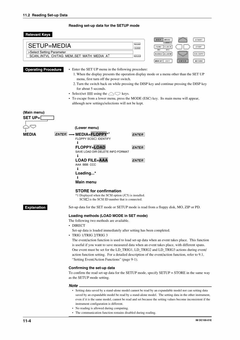
11-4 IM DC100-01E
Reading set-up data for the SETUP mode
RECORD
ALARM
KEYLOCK
SETUP=MEDIA
SCAN_INTVL CH/TAG MEM_SET MATH MEDIA A↑>Select Setting Parameter
D I S P M O D E
C L O C KF U N C
I N S D E L
R A N G E A L A R M
S E TMEM SET E N T E R
S T O P
F D C O P Y
M. F U N C
S T A R TE S C
• Enter the SET UP menu in the following procedure:1. When the display presents the operation display mode or a menu other than the SET UP
menu, first turn off the power switch.2. Turn the switch back on while pressing the DISP key and continue pressing the DISP key
for about 5 seconds.• Select/set using the keys.• To escape from a lower menu, press the MODE (ESC) key. Its main menu will appear,
although new settings/selections will not be kept.
MEDIA ENTER
SET UP=
MEDIA=FLOPPY*1 ENTERFLOPPY SCSI IDENTIFY
FLOPPY=LOAD ENTERSAVE LOAD DIR DELETE INFO FORMAT
LOAD FILE=AAA ENTERAAA BBB CCC
Loading...*
Main menu
STORE for confirmation*1 Displayed when the SCSI option (/C5) is installed.
(Main menu)
(Lower menu)
SCSI is the SCSI ID number that is connected.
Set-up data for the SET mode or SETUP mode is read from a floppy disk, MO, ZIP or PD.
Loading methods (LOAD MODE in SET mode)The following two methods are available.• DIRECT
Set-up data is loaded immediately after setting has been completed.• TRIG 1/TRIG 2/TRIG 3
The event/action function is used to load set-up data when an event takes place. This functionis useful if you want to save measured data when an event takes place, with different spans.One event must be set for the LD_TRIG1, LD_TRIG2 and LD_TRIG3 actions during event/action function setting. For a detailed description of the event/action function, refer to 9.1,“Setting Event/Action Functions” (page 9-1).
Confirming the set-up dataTo confirm the read set-up data for the SETUP mode, specify SETUP = STORE in the same wayas the SETUP mode setting.
Note• Setting data saved by a stand-alone model cannot be read by an expandable model nor can setting data
saved by an expandable model be read by a stand-alone model. The setting data in the other instrument,even if it is the same model, cannot be read and set because the setting values become inconsistent if theinstrument configuration is different.
• No reading is allowed during computing.• The communication function remains disabled during reading.
11.2 Reading Set-up Data
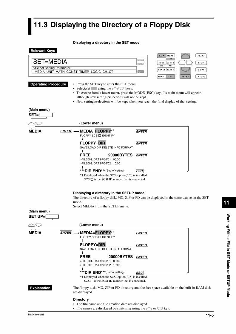
11-5IM DC100-01E
Wo
rking
With
a File in
SE
T M
od
e or S
ET
UP
Mo
de
11
11.3 Displaying the Directory of a Floppy Disk
Displaying a directory in the SET mode
RECORD
ALARM
KEYLOCK
SET=MEDIA
MEDIA UNIT MATH CONST TIMER LOGIC CH_C↑>Select Setting Parameter
D I S P M O D E
C L O C KF U N C
I N S D E L
R A N G E A L A R M
S E TMEM SET E N T E R
S T O P
F D C O P Y
M. F U N C
S T A R TE S C
• Press the SET key to enter the SET menu.• Select/set using the keys.• To escape from a lower menu, press the MODE (ESC) key. Its main menu will appear,
although new settings/selections will not be kept.• New settings/selections will be kept when you reach the final display of that setting.
MEDIA ENTER
SET=(Main menu)
(Lower menu)
MEDIA=FLOPPY*1 ENTERFLOPPY SCSI IDENTIFY
FLOPPY=DIR ENTERSAVE LOAD DIR DELETE INFO FORMAT
FREE 20000BYTES ENTER>FILE001. DAT 97/06/01 06:30>FILE002. DAT 97/06/02 10:00
***DIR END***(End of setting) ESC*1 Displayed when the SCSI option(/C5) is installed.
SCSI is the SCSI ID number that is connected.
Displaying a directory in the SETUP modeThe directory of a floppy disk, MO, ZIP or PD can be displayed in the same way as in the SETmode.Select MEDIA from the SETUP menu.
MEDIA ENTER
SET UP=(Main menu)
(Lower menu)
MEDIA=FLOPPY*1 ENTERFLOPPY SCSI IDENTIFY
FLOPPY=DIR ENTERSAVE LOAD DIR DELETE INFO FORMAT
FREE 20000BYTES ENTER>FILE001. DAT 97/06/01 06:30>FILE002. DAT 97/06/02 10:00
***DIR END***(End of setting) ESC*1 Displayed when the SCSI option(/C5) is installed.
SCSI is the SCSI ID number that is connected.
The floppy disk, MO, ZIP or PD directory and the free space available on the built-in RAM diskare displayed.
Directory• The file name and file creation date are displayed.• File names are displayed by switching using the or key.
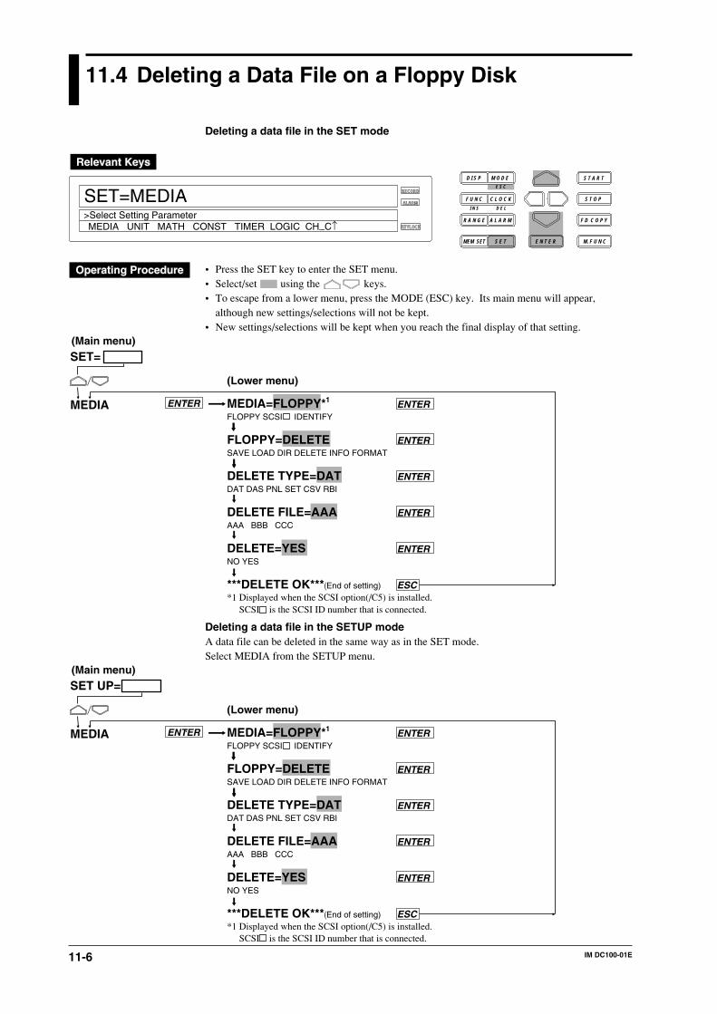
11-6 IM DC100-01E
11.4 Deleting a Data File on a Floppy Disk
Deleting a data file in the SET mode
RECORD
ALARM
KEYLOCK
SET=MEDIA
MEDIA UNIT MATH CONST TIMER LOGIC CH_C↑>Select Setting Parameter
D I S P M O D E
C L O C KF U N C
I N S D E L
R A N G E A L A R M
S E TMEM SET E N T E R
S T O P
F D C O P Y
M. F U N C
S T A R TE S C
• Press the SET key to enter the SET menu.• Select/set using the keys.• To escape from a lower menu, press the MODE (ESC) key. Its main menu will appear,
although new settings/selections will not be kept.• New settings/selections will be kept when you reach the final display of that setting.
SET=
MEDIA ENTER MEDIA=FLOPPY*1 ENTERFLOPPY SCSI IDENTIFY
FLOPPY=DELETE ENTERSAVE LOAD DIR DELETE INFO FORMAT
DELETE TYPE=DAT ENTERDAT DAS PNL SET CSV RBI
DELETE FILE=AAA ENTERAAA BBB CCC
DELETE=YES ENTERNO YES
***DELETE OK***(End of setting) ESC*1 Displayed when the SCSI option(/C5) is installed.
(Main menu)
(Lower menu)
SCSI is the SCSI ID number that is connected.
Deleting a data file in the SETUP modeA data file can be deleted in the same way as in the SET mode.Select MEDIA from the SETUP menu.
SET UP=
MEDIA ENTER MEDIA=FLOPPY*1 ENTERFLOPPY SCSI IDENTIFY
FLOPPY=DELETE ENTERSAVE LOAD DIR DELETE INFO FORMAT
DELETE TYPE=DAT ENTERDAT DAS PNL SET CSV RBI
DELETE FILE=AAA ENTERAAA BBB CCC
DELETE=YES ENTERNO YES
***DELETE OK***(End of setting) ESC*1 Displayed when the SCSI option(/C5) is installed.
(Main menu)
(Lower menu)
SCSI is the SCSI ID number that is connected.

11-7IM DC100-01E
Wo
rking
With
a File in
SE
T M
od
e or S
ET
UP
Mo
de
11
A file saved on a floppy disk, MO, ZIP or PD is deleted.
Type of File to Be DeletedDAT: Deletes the measured/computed data.DAS: Deletes the periodic file.RBI: Deletes the report data.PNL: Deletes the setting data in the SET mode.SET: Deletes the setting data in the SETUP mode.CSV: Deletes the measured data converted to ASCII format.
Acknowledging File DeletionYES: Deletes the file.NO: Does not delete the file.
NoteThe communication function is disabled during deletion.
11.4 Deleting a Data File on a Floppy Disk
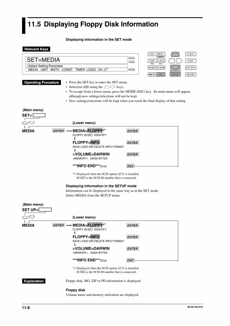
11-8 IM DC100-01E
11.5 Displaying Floppy Disk Information
Displaying information in the SET mode
RECORD
ALARM
KEYLOCK
SET=MEDIA
MEDIA UNIT MATH CONST TIMER LOGIC CH_C↑>Select Setting Parameter
D I S P M O D E
C L O C KF U N C
I N S D E L
R A N G E A L A R M
S E TMEM SET E N T E R
S T O P
F D C O P Y
M. F U N C
S T A R TE S C
• Press the SET key to enter the SET menu.• Select/set using the keys.• To escape from a lower menu, press the MODE (ESC) key. Its main menu will appear,
although new settings/selections will not be kept.• New settings/selections will be kept when you reach the final display of that setting.
SET=
MEDIA ENTER MEDIA=FLOPPY*1 ENTERFLOPPY SCSI IDENTIFY
FLOPPY=INFO ENTERSAVE LOAD DIR DELETE INFO FORMAT
>VOLUME=DARWIN ENTER>MEMORY= 20000 BYTES
***INFO END***(End) ESC
*1 Displayed when the SCSI option (/C5) is installed.
(Main menu)
(Lower menu)
SCSI is the SCSI ID number that is connected.
Displaying information in the SETUP modeInformation can be displayed in the same way as in the SET mode.Select MEDIA from the SETUP menu.
SET UP=
MEDIA ENTER MEDIA=FLOPPY*1 ENTERFLOPPY SCSI IDENTIFY
FLOPPY=INFO ENTERSAVE LOAD DIR DELETE INFO FORMAT
>VOLUME=DARWIN ENTER>MEMORY= 20000 BYTES
***INFO END***(End) ESC
*1 Displayed when the SCSI option (/C5) is installed.
(Main menu)
(Lower menu)
SCSI is the SCSI ID number that is connected.
Floppy disk, MO, ZIP or PD information is displayed.
Floppy diskVolume name and memory utilization are displayed.
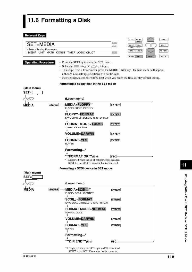
11-9IM DC100-01E
Wo
rking
With
a File in
SE
T M
od
e or S
ET
UP
Mo
de
11
11.6 Formatting a Disk
RECORD
ALARM
KEYLOCK
SET=MEDIA
MEDIA UNIT MATH CONST TIMER LOGIC CH_C↑>Select Setting Parameter
D I S P M O D E
C L O C KF U N C
I N S D E L
R A N G E A L A R M
S E TMEM SET E N T E R
S T O P
F D C O P Y
M. F U N C
S T A R TE S C
• Press the SET key to enter the SET menu.• Select/set using the keys.• To escape from a lower menu, press the MODE (ESC) key. Its main menu will appear,
although new settings/selections will not be kept.• New settings/selections will be kept when you reach the final display of that setting.
Formating a floppy disk in the SET mode
SET=
MEDIA ENTER MEDIA=FLOPPY*1 ENTERFLOPPY SCSI IDENTIFY
FLOPPY=FORMAT ENTERSAVE LOAD DIR DELETE INFO FORMAT
FORMAT MODE=1.44MB ENTER1.2MB 720KB 1.44MB
VOLUME=DARWIN ENTER
FORMAT=YES ENTERNO YES
Formatting...*
***FORMAT OK***(End) ESC*1 Displayed when the SCSI option(/C5) is installed.
(Main menu)
(Lower menu)
SCSI is the SCSI ID number that is connected.
Formating a SCSI device in SET mode
SET=
MEDIA ENTER MEDIA=SCSI *1 ENTERFLOPPY SCSI IDENTIFY
SCSI =FORMAT ENTERSAVE LOAD DIR DELETE INFO FORMAT
FORMAT MODE=NORMAL ENTERNORMAL QUICK
VOLUME=DARWIN ENTER
FORMAT=YES ENTERNO YES
Formatting...*
***DIR END***(End) ESC
*1 Displayed when the SCSI option(/C5) is installed.
(Main menu)
(Lower menu)
SCSI is the SCSI ID number that is connected.
11-10 IM DC100-01E
Formatting a floppy disk, MO, ZIP or PD in the SETUP modeA floppy disk, MO, ZIP or PD can be formatted in the same way as in the SET mode.Select MEDIA from the SETUP menu.The rest of the procedure is the same as in the SET menu.
A floppy disk, MO, ZIP or PD is formatted. All the data on the floppy disk will be deleted. Thus,copy necessary data to another media before carrying out formatting.
Format mode (FORMAT MODE)Select the format mode from the following.2HD: 1.44 MB, 1.2 MB2DD: 720 KB
Disk FormatThe format of the MO disk, ZIP or PD connected to the SCSI (option) is semi-IBM format.
Disk Format ModeNORMAL: Performs both physical format and logical format.QUICK: Performs logical format only.The time needed to format the disks are as follows.
Media NORMAL QUICK
MO (128 MB) About 15 min About 5 sMO (230 MB) About 15 min About 5 sZIP About 10 min About 5 sPD About 30 min About 5 s
Use MO/ZIP/PD disks that are formatted on the DC100.
Volume nameBeginning the volume name with a space is not allowed. If this happens, an error will occur.
NoteThe communication function is disabled during formatting.
Precautions to be taken during formatting• If a floppy disk that contains data is formatted, all the data on the disk will be lost.• Formatting for a floppy disk takes approx. one-and-half minutes.• Before starting formatting, make sure that the write protection tab on the floppy disk is
released.
Note• Logical (Quick) format only clears (initializes) the directory entries and the FAT. If you wish to check
for bad sectors, do a physical (Normal) format also.• If writing data to an external SCSI device having bad sectors no more data can be written to the device.
As a guideline, do a Normal format on disks used for the first time or disks which can no longer be reador written, and a Quick format on disks which have been used previously.
11.6 Formatting a Disk
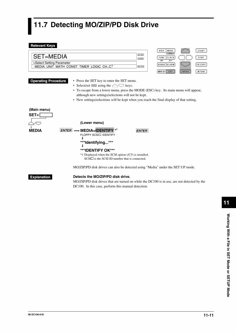
11-11IM DC100-01E
Wo
rking
With
a File in
SE
T M
od
e or S
ET
UP
Mo
de
11
11.7 Detecting MO/ZIP/PD Disk Drive
RECORD
ALARM
KEYLOCK
SET=MEDIA
MEDIA UNIT MATH CONST TIMER LOGIC CH_C↑>Select Setting Parameter
D I S P M O D E
C L O C KF U N C
I N S D E L
R A N G E A L A R M
S E TMEM SET E N T E R
S T O P
F D C O P Y
M. F U N C
S T A R TE S C
• Press the SET key to enter the SET menu.• Select/set using the keys.• To escape from a lower menu, press the MODE (ESC) key. Its main menu will appear,
although new settings/selections will not be kept.• New settings/selections will be kept when you reach the final display of that setting.
SET=
MEDIA ENTER MEDIA=IDENTIFY *1 ENTERFLOPPY SCSI IDENTIFY
***Identifying...***
***IDENTIFY OK****1 Displayed when the SCSI option (/C5) is installed.
(Main menu)
(Lower menu)
SCSI is the SCSI ID number that is connected.
MO/ZIP/PD disk drives can also be detected using "Media" under the SET UP mode.
Detects the MO/ZIP/PD disk drive.MO/ZIP/PD disk drives that are turned on while the DC100 is in use, are not detected by theDC100. In this case, perform this manual detection.
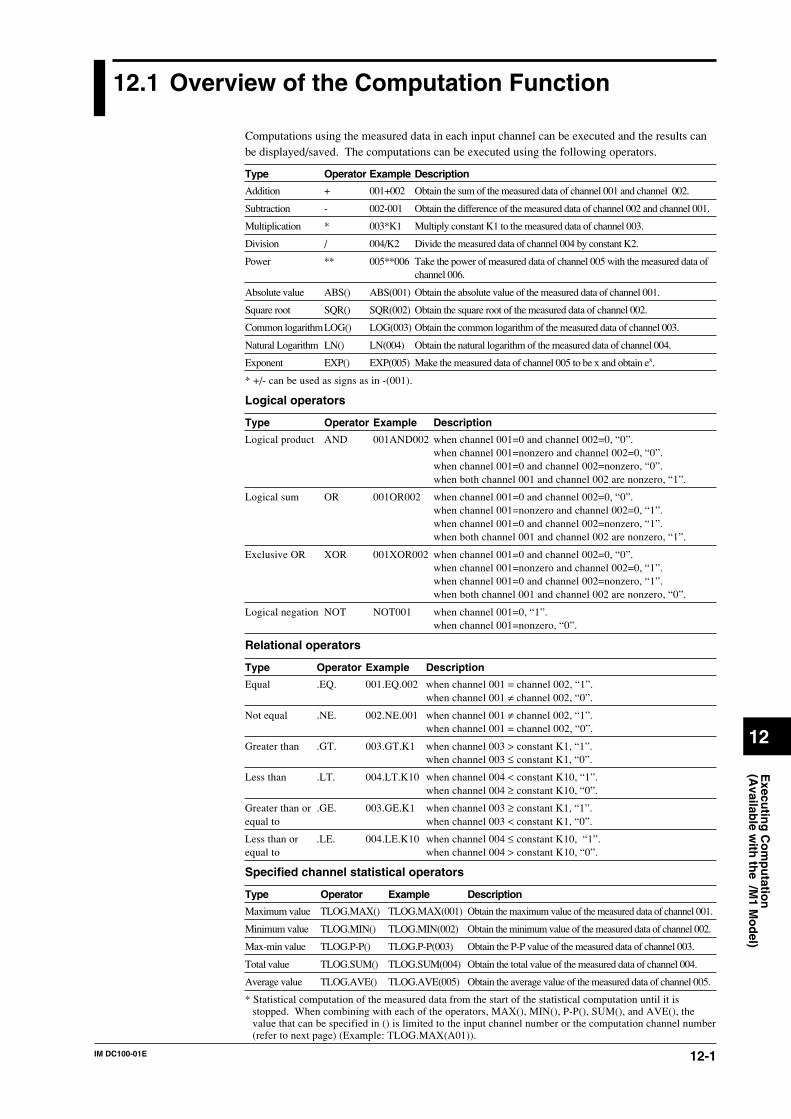
12-1IM DC100-01E
Execu
ting
Co
mp
utatio
n(A
vailable w
ith th
e /M1 M
od
el)
12
12.1 Overview of the Computation Function
Computations using the measured data in each input channel can be executed and the results canbe displayed/saved. The computations can be executed using the following operators.
Type Operator Example Description
Addition + 001+002 Obtain the sum of the measured data of channel 001 and channel 002.
Subtraction - 002-001 Obtain the difference of the measured data of channel 002 and channel 001.
Multiplication * 003*K1 Multiply constant K1 to the measured data of channel 003.
Division / 004/K2 Divide the measured data of channel 004 by constant K2.
Power ** 005**006 Take the power of measured data of channel 005 with the measured data ofchannel 006.
Absolute value ABS() ABS(001) Obtain the absolute value of the measured data of channel 001.
Square root SQR() SQR(002) Obtain the square root of the measured data of channel 002.
Common logarithmLOG() LOG(003) Obtain the common logarithm of the measured data of channel 003.
Natural Logarithm LN() LN(004) Obtain the natural logarithm of the measured data of channel 004.
Exponent EXP() EXP(005) Make the measured data of channel 005 to be x and obtain ex.
* +/- can be used as signs as in -(001).
Logical operators
Type Operator Example Description
Logical product AND 001AND002 when channel 001=0 and channel 002=0, “0”.when channel 001=nonzero and channel 002=0, “0”.when channel 001=0 and channel 002=nonzero, “0”.when both channel 001 and channel 002 are nonzero, “1”.
Logical sum OR 001OR002 when channel 001=0 and channel 002=0, “0”.when channel 001=nonzero and channel 002=0, “1”.when channel 001=0 and channel 002=nonzero, “1”.when both channel 001 and channel 002 are nonzero, “1”.
Exclusive OR XOR 001XOR002 when channel 001=0 and channel 002=0, “0”.when channel 001=nonzero and channel 002=0, “1”.when channel 001=0 and channel 002=nonzero, “1”.when both channel 001 and channel 002 are nonzero, “0”.
Logical negation NOT NOT001 when channel 001=0, “1”.when channel 001=nonzero, “0”.
Relational operators
Type Operator Example Description
Equal .EQ. 001.EQ.002 when channel 001 = channel 002, “1”.when channel 001 ≠ channel 002, “0”.
Not equal .NE. 002.NE.001 when channel 001 ≠ channel 002, “1”.when channel 001 = channel 002, “0”.
Greater than .GT. 003.GT.K1 when channel 003 > constant K1, “1”.when channel 003 ≤ constant K1, “0”.
Less than .LT. 004.LT.K10 when channel 004 < constant K10, “1”.when channel 004 ≥ constant K10, “0”.
Greater than or .GE. 003.GE.K1 when channel 003 ≥ constant K1, “1”.equal to when channel 003 < constant K1, “0”.
Less than or .LE. 004.LE.K10 when channel 004 ≤ constant K10, “1”.equal to when channel 004 > constant K10, “0”.
Specified channel statistical operators
Type Operator Example Description
Maximum value TLOG.MAX() TLOG.MAX(001) Obtain the maximum value of the measured data of channel 001.
Minimum value TLOG.MIN() TLOG.MIN(002) Obtain the minimum value of the measured data of channel 002.
Max-min value TLOG.P-P() TLOG.P-P(003) Obtain the P-P value of the measured data of channel 003.
Total value TLOG.SUM() TLOG.SUM(004) Obtain the total value of the measured data of channel 004.
Average value TLOG.AVE() TLOG.AVE(005) Obtain the average value of the measured data of channel 005.
* Statistical computation of the measured data from the start of the statistical computation until it isstopped. When combining with each of the operators, MAX(), MIN(), P-P(), SUM(), and AVE(), thevalue that can be specified in () is limited to the input channel number or the computation channel number(refer to next page) (Example: TLOG.MAX(A01)).
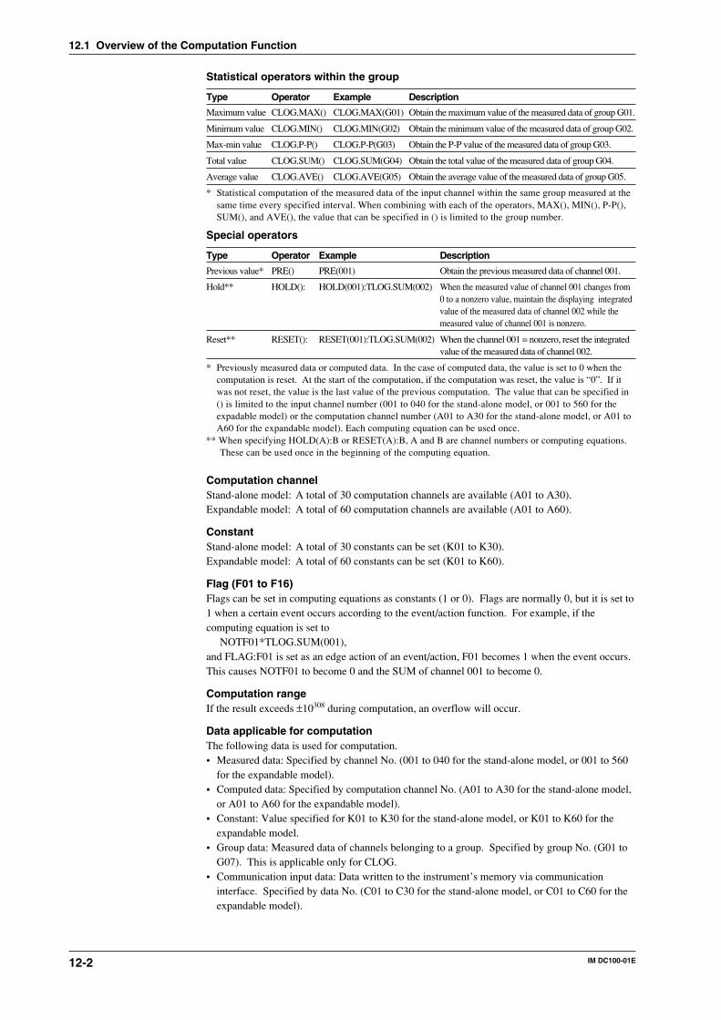
12-2 IM DC100-01E
12.1 Overview of the Computation Function
Statistical operators within the group
Type Operator Example Description
Maximum value CLOG.MAX() CLOG.MAX(G01) Obtain the maximum value of the measured data of group G01.
Minimum value CLOG.MIN() CLOG.MIN(G02) Obtain the minimum value of the measured data of group G02.
Max-min value CLOG.P-P() CLOG.P-P(G03) Obtain the P-P value of the measured data of group G03.
Total value CLOG.SUM() CLOG.SUM(G04) Obtain the total value of the measured data of group G04.
Average value CLOG.AVE() CLOG.AVE(G05) Obtain the average value of the measured data of group G05.
* Statistical computation of the measured data of the input channel within the same group measured at thesame time every specified interval. When combining with each of the operators, MAX(), MIN(), P-P(),SUM(), and AVE(), the value that can be specified in () is limited to the group number.
Special operators
Type Operator Example Description
Previous value* PRE() PRE(001) Obtain the previous measured data of channel 001.
Hold** HOLD(): HOLD(001):TLOG.SUM(002) When the measured value of channel 001 changes from0 to a nonzero value, maintain the displaying integratedvalue of the measured data of channel 002 while themeasured value of channel 001 is nonzero.
Reset** RESET(): RESET(001):TLOG.SUM(002) When the channel 001 = nonzero, reset the integratedvalue of the measured data of channel 002.
* Previously measured data or computed data. In the case of computed data, the value is set to 0 when thecomputation is reset. At the start of the computation, if the computation was reset, the value is “0”. If itwas not reset, the value is the last value of the previous computation. The value that can be specified in() is limited to the input channel number (001 to 040 for the stand-alone model, or 001 to 560 for theexpadable model) or the computation channel number (A01 to A30 for the stand-alone model, or A01 toA60 for the expandable model). Each computing equation can be used once.
** When specifying HOLD(A):B or RESET(A):B, A and B are channel numbers or computing equations.These can be used once in the beginning of the computing equation.
Computation channelStand-alone model: A total of 30 computation channels are available (A01 to A30).Expandable model: A total of 60 computation channels are available (A01 to A60).
ConstantStand-alone model: A total of 30 constants can be set (K01 to K30).Expandable model: A total of 60 constants can be set (K01 to K60).
Flag (F01 to F16)Flags can be set in computing equations as constants (1 or 0). Flags are normally 0, but it is set to1 when a certain event occurs according to the event/action function. For example, if thecomputing equation is set to
NOTF01*TLOG.SUM(001),and FLAG:F01 is set as an edge action of an event/action, F01 becomes 1 when the event occurs.This causes NOTF01 to become 0 and the SUM of channel 001 to become 0.
Computation rangeIf the result exceeds ±10308 during computation, an overflow will occur.
Data applicable for computationThe following data is used for computation.• Measured data: Specified by channel No. (001 to 040 for the stand-alone model, or 001 to 560
for the expandable model).• Computed data: Specified by computation channel No. (A01 to A30 for the stand-alone model,
or A01 to A60 for the expandable model).• Constant: Value specified for K01 to K30 for the stand-alone model, or K01 to K60 for the
expandable model.• Group data: Measured data of channels belonging to a group. Specified by group No. (G01 to
G07). This is applicable only for CLOG.• Communication input data: Data written to the instrument’s memory via communication
interface. Specified by data No. (C01 to C30 for the stand-alone model, or C01 to C60 for theexpandable model).
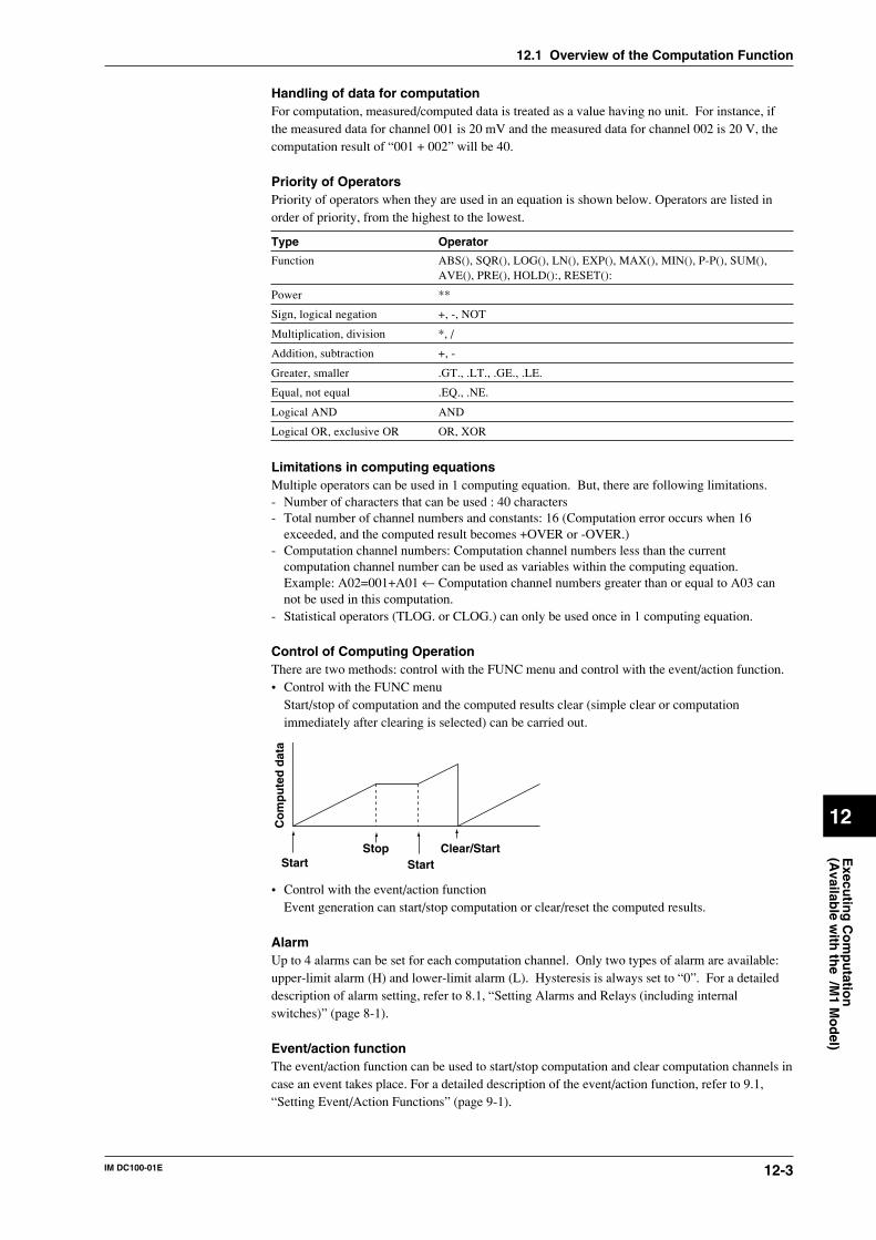
12-3IM DC100-01E
Execu
ting
Co
mp
utatio
n(A
vailable w
ith th
e /M1 M
od
el)
12
12.1 Overview of the Computation Function
Handling of data for computationFor computation, measured/computed data is treated as a value having no unit. For instance, ifthe measured data for channel 001 is 20 mV and the measured data for channel 002 is 20 V, thecomputation result of “001 + 002” will be 40.
Priority of OperatorsPriority of operators when they are used in an equation is shown below. Operators are listed inorder of priority, from the highest to the lowest.
Type Operator
Function ABS(), SQR(), LOG(), LN(), EXP(), MAX(), MIN(), P-P(), SUM(),AVE(), PRE(), HOLD():, RESET():
Power **
Sign, logical negation +, -, NOT
Multiplication, division *, /
Addition, subtraction +, -
Greater, smaller .GT., .LT., .GE., .LE.
Equal, not equal .EQ., .NE.
Logical AND AND
Logical OR, exclusive OR OR, XOR
Limitations in computing equationsMultiple operators can be used in 1 computing equation. But, there are following limitations.- Number of characters that can be used : 40 characters- Total number of channel numbers and constants: 16 (Computation error occurs when 16
exceeded, and the computed result becomes +OVER or -OVER.)- Computation channel numbers: Computation channel numbers less than the current
computation channel number can be used as variables within the computing equation.Example: A02=001+A01 ← Computation channel numbers greater than or equal to A03 cannot be used in this computation.
- Statistical operators (TLOG. or CLOG.) can only be used once in 1 computing equation.
Control of Computing OperationThere are two methods: control with the FUNC menu and control with the event/action function.• Control with the FUNC menu
Start/stop of computation and the computed results clear (simple clear or computationimmediately after clearing is selected) can be carried out.
Start StartStop Clear/Start
Co
mp
ute
d d
ata
• Control with the event/action functionEvent generation can start/stop computation or clear/reset the computed results.
AlarmUp to 4 alarms can be set for each computation channel. Only two types of alarm are available:upper-limit alarm (H) and lower-limit alarm (L). Hysteresis is always set to “0”. For a detaileddescription of alarm setting, refer to 8.1, “Setting Alarms and Relays (including internalswitches)” (page 8-1).
Event/action functionThe event/action function can be used to start/stop computation and clear computation channels incase an event takes place. For a detailed description of the event/action function, refer to 9.1,“Setting Event/Action Functions” (page 9-1).
12-4 IM DC100-01E
Actions to be taken in case of overflow and computation errorActions to be taken in case of an error during computation can be specified.• Error display: +OVER or -OVER is displayed.• Error data during TLOG or CLOG: The operator is asked to select whether to display the data
as a computation error or ignore the error and continue computation.• Overflow data during TLOG or CLOG: The operator is asked to select whether to display the
data as a computation error or ignore the error and continue computation. The operator is alsoasked to select whether or not the data be used as the upper-/lower-limit value.Description of the upper-/lower-limit value is given below:
Measurement channels to which linear scaling is applied: Specified scaling upper-/lower-limitMeasurement channels to which no linear scaling is applied: Upper-/lower-limit of themeasuring rangeComputation channels: Specified LEFT/RIGHT value
Group ResetBy using the event/action function, you can reset the computed values of computed channelsregistered in the group.
12.1 Overview of the Computation Function
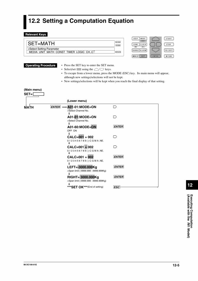
12-5IM DC100-01E
Execu
ting
Co
mp
utatio
n(A
vailable w
ith th
e /M1 M
od
el)
12
12.2 Setting a Computation Equation
RECORD
ALARM
KEYLOCK
SET=MATH
MEDIA UNIT MATH CONST TIMER LOGIC CH_C↑>Select Setting Parameter
D I S P M O D E
C L O C KF U N C
I N S D E L
R A N G E A L A R M
S E TMEM SET E N T E R
S T O P
F D C O P Y
M. F U N C
S T A R TE S C
• Press the SET key to enter the SET menu.• Select/set using the keys.• To escape from a lower menu, press the MODE (ESC) key. Its main menu will appear,
although new settings/selections will not be kept.• New settings/selections will be kept when you reach the final display of that setting.
ENTER
ENTER
A01-01:MODE=ON>Select Channel No.
A01-01:MODE=ON>Select Channel No.
A01-60:MODE=ONOFF ON
CALC=001 + 0020 1 2 3 4 5 6 7 8 9 ( ) C G M A .NE.
CALC=001 + 0020 1 2 3 4 5 6 7 8 9 ( ) C G M A .NE.
CALC=001 + 0020 1 2 3 4 5 6 7 8 9 ( ) C G M A .NE.
LEFT=-3000.000Kg>Span limit (-9999.999 ~9999.999Kg)
RIGHT= 3000.000Kg>Span limit (-9999.999 ~9999.999Kg)
***SET OK***(End of setting)
ENTER
ENTER
SET=
MATH
ESC
(Main menu)
(Lower menu)
ENTER
12-6 IM DC100-01E
For the stand-alone model, a computation equation can be set for up to 30 channels (A01 to A30).For the expandable model, a computation equation can be set for up to 60 channels (A01 to A60).
Setting the modeIf “A01-60 MODE=ON” is specified as in the example given on the previous page, the sameequation can be set for channels A01 to A60. To set an equation for one channel only, specify,for instance, “A01-A01 MODE=ON”.
Computation equationIn addition to operators described on page 12-1, the following symbols can be used in equations.
(/) : Used for ( ) setting.K : Used if equations contain constants K01 to K60 (or K01 to K30 for the stand-alone model).A : Used to specify the computation channel No. as in “A05.”C : Used to specify communication input data (digital data).G : Used to specify the group No. for which CLOG (computation of data of a group measured
on the same time) is to be used.
Restrictions in equationsComputation channel No• The specified computation equation for a computation channel No. can contain only
computation channel Nos. as variables which are equal to or smaller than the said computationchannel No.(Example) A02=001+A01In this example, any computation channel No. which is equal to or greater than A03 cannot beused.
• Either TLOG or CLOG can be used in an equation.
Note• Each equation must consist of up to 40 characters.• The total number of channels and constants to be used for each equation is 16 or smaller.
Setting the spanThe upper and lower limits of the computed results are set. The computed results, if theyoverreach these limits, are handled as over data. The setting range is from -9999999 to 99999999.The decimal point can be placed in five positions, as represented in x.xxxx, xx.xxx, xxx.xx,xxxx.x, xxxxx.. The unit specified in 8.3, “Setting the Engineering Unit” (page 8-5) will be used.LEFT : Sets the lower-limit value.RIGHT: Sets the upper-limit value.
NoteIf the computation ON/OFF, computation equation or span setting is changed, the alarm setting for thecorresponding channel will be reset.
12.2 Setting a Computation Equation
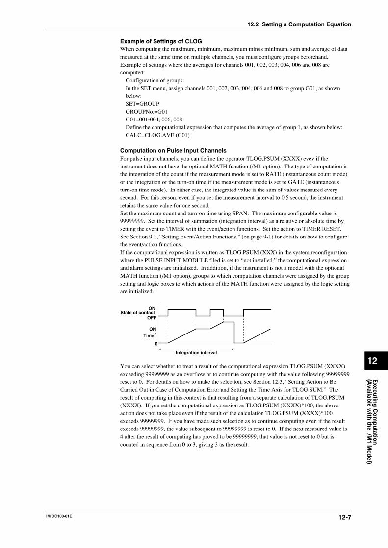
12-7IM DC100-01E
Execu
ting
Co
mp
utatio
n(A
vailable w
ith th
e /M1 M
od
el)
12
Example of Settings of CLOGWhen computing the maximum, minimum, maximum minus minimum, sum and average of datameasured at the same time on multiple channels, you must configure groups beforehand.Example of settings where the averages for channels 001, 002, 003, 004, 006 and 008 arecomputed:
Configuration of groups:In the SET menu, assign channels 001, 002, 003, 004, 006 and 008 to group G01, as shownbelow:SET=GROUPGROUPNo.=G01G01=001-004, 006, 008Define the computational expression that computes the average of group 1, as shown below:CALC=CLOG.AVE (G01)
Computation on Pulse Input ChannelsFor pulse input channels, you can define the operator TLOG.PSUM (XXXX) evev if theinstrument does not have the optional MATH function (/M1 option). The type of computation isthe integration of the count if the measurement mode is set to RATE (instantaneous count mode)or the integration of the turn-on time if the measurement mode is set to GATE (instantaneousturn-on time mode). In either case, the integrated value is the sum of values measured everysecond. For this reason, even if you set the measurement interval to 0.5 second, the instrumentretains the same value for one second.Set the maximum count and turn-on time using SPAN. The maximum configurable value is99999999. Set the interval of summation (integration interval) as a relative or absolute time bysetting the event to TIMER with the event/action functions. Set the action to TIMER RESET.See Section 9.1, “Setting Event/Action Functions,” (on page 9-1) for details on how to configurethe event/action functions.If the computational expression is written as TLOG.PSUM (XXX) in the system reconfigurationwhere the PULSE INPUT MODULE filed is set to “not installed,” the computational expressionand alarm settings are initialized. In addition, if the instrument is not a model with the optionalMATH function (/M1 option), groups to which computation channels were assigned by the groupsetting and logic boxes to which actions of the MATH function were assigned by the logic settingare initialized.
Integration interval
Time
State of contactON
OFF
0
ON
You can select whether to treat a result of the computational expression TLOG.PSUM (XXXX)exceeding 99999999 as an overflow or to continue computing with the value following 99999999reset to 0. For details on how to make the selection, see Section 12.5, “Setting Action to BeCarried Out in Case of Computation Error and Setting the Time Axis for TLOG SUM.” Theresult of computing in this context is that resulting from a separate calculation of TLOG.PSUM(XXXX). If you set the computational expression as TLOG.PSUM (XXXX)*100, the aboveaction does not take place even if the result of the calculation TLOG.PSUM (XXXX)*100exceeds 99999999. If you have made such selection as to continue computing even if the resultexceeds 99999999, the value subsequent to 99999999 is reset to 0. If the next measured value is4 after the result of computing has proved to be 99999999, that value is not reset to 0 but iscounted in sequence from 0 to 3, giving 3 as the result.
12.2 Setting a Computation Equation
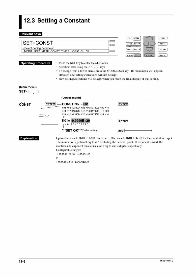
12-8 IM DC100-01E
12.3 Setting a Constant
RECORD
ALARM
KEYLOCK
SET=CONST
MEDIA UNIT MATH CONST TIMER LOGIC CH_C↑>Select Setting Parameter
D I S P M O D E
C L O C KF U N C
I N S D E L
R A N G E A L A R M
S E TMEM SET E N T E R
S T O P
F D C O P Y
M. F U N C
S T A R TE S C
• Press the SET key to enter the SET menu.• Select/set using the keys.• To escape from a lower menu, press the MODE (ESC) key. Its main menu will appear,
although new settings/selections will not be kept.• New settings/selections will be kept when you reach the final display of that setting.
CONST No. =K01K01 K02 K03 K04 K05 K06 K07 K08 K09 K10K11 K12 K13 K14 K15 K16 K17 K18 K19 K20K21 K22 K23 K24 K25 K26 K27 K28 K29 K30
K01= -9.9999E+29. - + 0 1 2 3 4 5 6 7 8 9 E
***SET OK***(End of setting)
ENTER
SET=
CONST
ESC
(Main menu)
(Lower menu)
ENTER
ENTER
Up to 60 constants (K01 to K60) can be set. (30 constants (K01 to K30) for the stand-alone type)The number of significant digits is 5 excluding the decimal point. If exponent is used, themantissa and exponent must consist of 5 digits and 2 digits, respectively.Configurable ranges:-1.0000E+35 to -1.0000E-3501.0000E-35 to -1.0000E+35
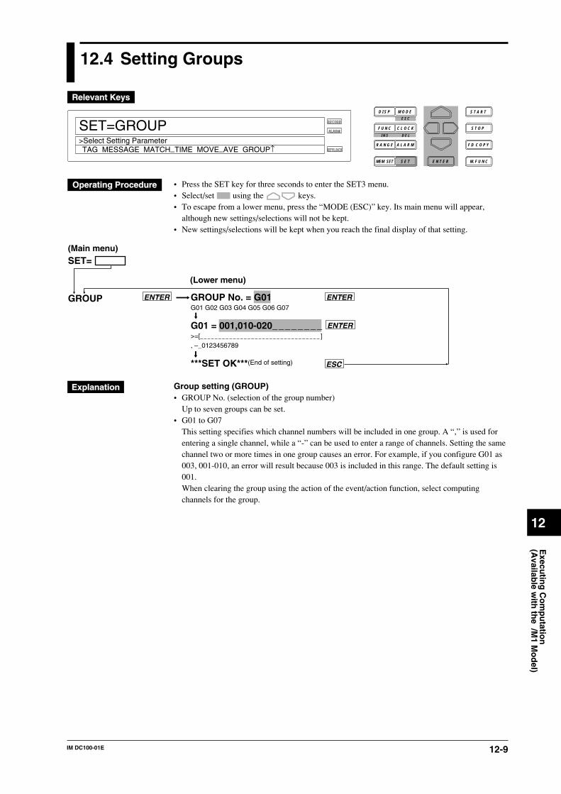
12-9IM DC100-01E
Execu
ting
Co
mp
utatio
n(A
vailable w
ith th
e /M1 M
od
el)
12
12.4 Setting Groups
RECORD
ALARM
KEYLOCK
SET=GROUP
TAG MESSAGE MATCH_TIME MOVE_AVE GROUP↑>Select Setting Parameter
D I S P M O D E
C L O C KF U N C
I N S D E L
R A N G E A L A R M
S E TMEM SET E N T E R
S T O P
F D C O P Y
M. F U N C
S T A R TE S C
• Press the SET key for three seconds to enter the SET3 menu.• Select/set using the keys.• To escape from a lower menu, press the “MODE (ESC)” key. Its main menu will appear,
although new settings/selections will not be kept.• New settings/selections will be kept when you reach the final display of that setting.
ENTER
GROUP No. = G01G01 G02 G03 G04 G05 G06 G07
G01 = 001,010-020________>=[_ _ _ _ _ _ _ _ _ _ _ _ _ _ _ _ _ _ _ _ _ _ _ _ _ _ _ _ _ _ _ _ _ ], –_0123456789
***SET OK***(End of setting)
ENTER
SET=
GROUP
ESC
(Main menu)
(Lower menu)
ENTER
Group setting (GROUP)• GROUP No. (selection of the group number)
Up to seven groups can be set.• G01 to G07
This setting specifies which channel numbers will be included in one group. A “,” is used forentering a single channel, while a “-” can be used to enter a range of channels. Setting the samechannel two or more times in one group causes an error. For example, if you configure G01 as003, 001-010, an error will result because 003 is included in this range. The default setting is001.When clearing the group using the action of the event/action function, select computingchannels for the group.
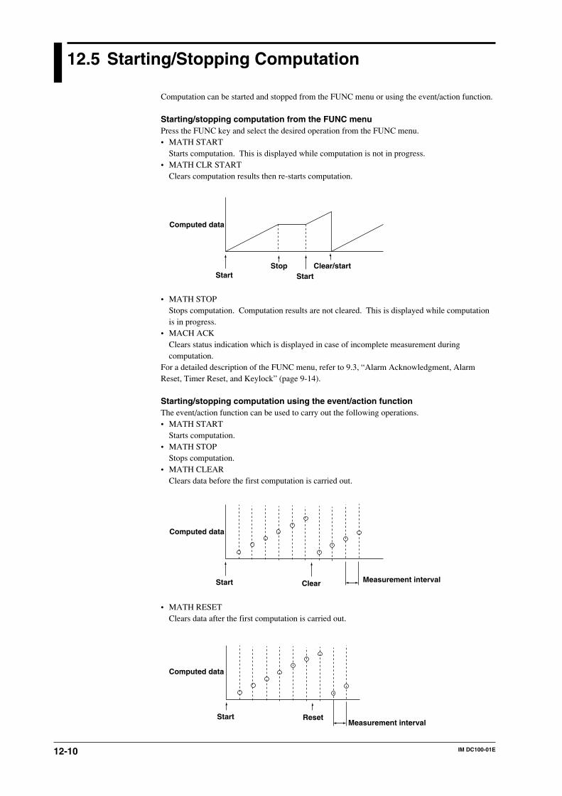
12-10 IM DC100-01E
12.5 Starting/Stopping Computation
Computation can be started and stopped from the FUNC menu or using the event/action function.
Starting/stopping computation from the FUNC menuPress the FUNC key and select the desired operation from the FUNC menu.• MATH START
Starts computation. This is displayed while computation is not in progress.• MATH CLR START
Clears computation results then re-starts computation.
Start
Computed data
StartStop Clear/start
• MATH STOPStops computation. Computation results are not cleared. This is displayed while computationis in progress.
• MACH ACKClears status indication which is displayed in case of incomplete measurement duringcomputation.
For a detailed description of the FUNC menu, refer to 9.3, “Alarm Acknowledgment, AlarmReset, Timer Reset, and Keylock” (page 9-14).
Starting/stopping computation using the event/action functionThe event/action function can be used to carry out the following operations.• MATH START
Starts computation.• MATH STOP
Stops computation.• MATH CLEAR
Clears data before the first computation is carried out.
Start Clear Measurement interval
Computed data
• MATH RESETClears data after the first computation is carried out.
Start ResetMeasurement interval
Computed data
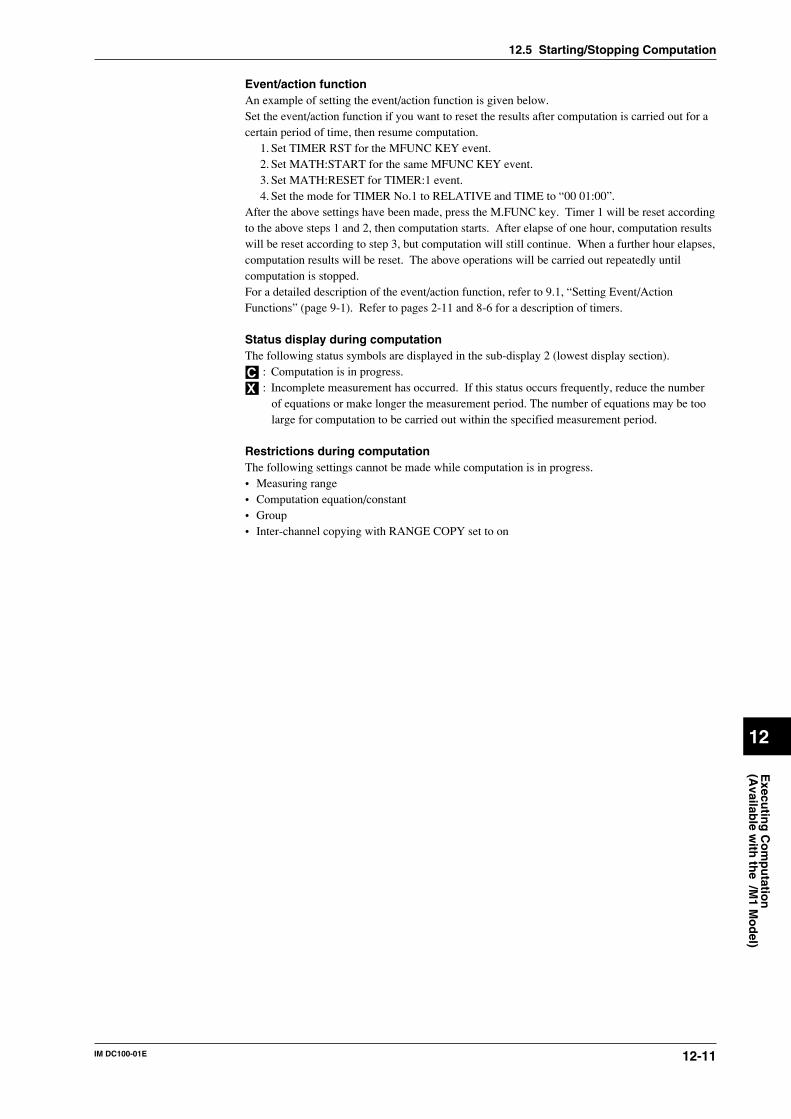
12-11IM DC100-01E
Execu
ting
Co
mp
utatio
n(A
vailable w
ith th
e /M1 M
od
el)
12
Event/action functionAn example of setting the event/action function is given below.Set the event/action function if you want to reset the results after computation is carried out for acertain period of time, then resume computation.
1. Set TIMER RST for the MFUNC KEY event.2. Set MATH:START for the same MFUNC KEY event.3. Set MATH:RESET for TIMER:1 event.4. Set the mode for TIMER No.1 to RELATIVE and TIME to “00 01:00”.
After the above settings have been made, press the M.FUNC key. Timer 1 will be reset accordingto the above steps 1 and 2, then computation starts. After elapse of one hour, computation resultswill be reset according to step 3, but computation will still continue. When a further hour elapses,computation results will be reset. The above operations will be carried out repeatedly untilcomputation is stopped.For a detailed description of the event/action function, refer to 9.1, “Setting Event/ActionFunctions” (page 9-1). Refer to pages 2-11 and 8-6 for a description of timers.
Status display during computationThe following status symbols are displayed in the sub-display 2 (lowest display section).
C : Computation is in progress.
X : Incomplete measurement has occurred. If this status occurs frequently, reduce the numberof equations or make longer the measurement period. The number of equations may be toolarge for computation to be carried out within the specified measurement period.
Restrictions during computationThe following settings cannot be made while computation is in progress.• Measuring range• Computation equation/constant• Group• Inter-channel copying with RANGE COPY set to on
12.5 Starting/Stopping Computation
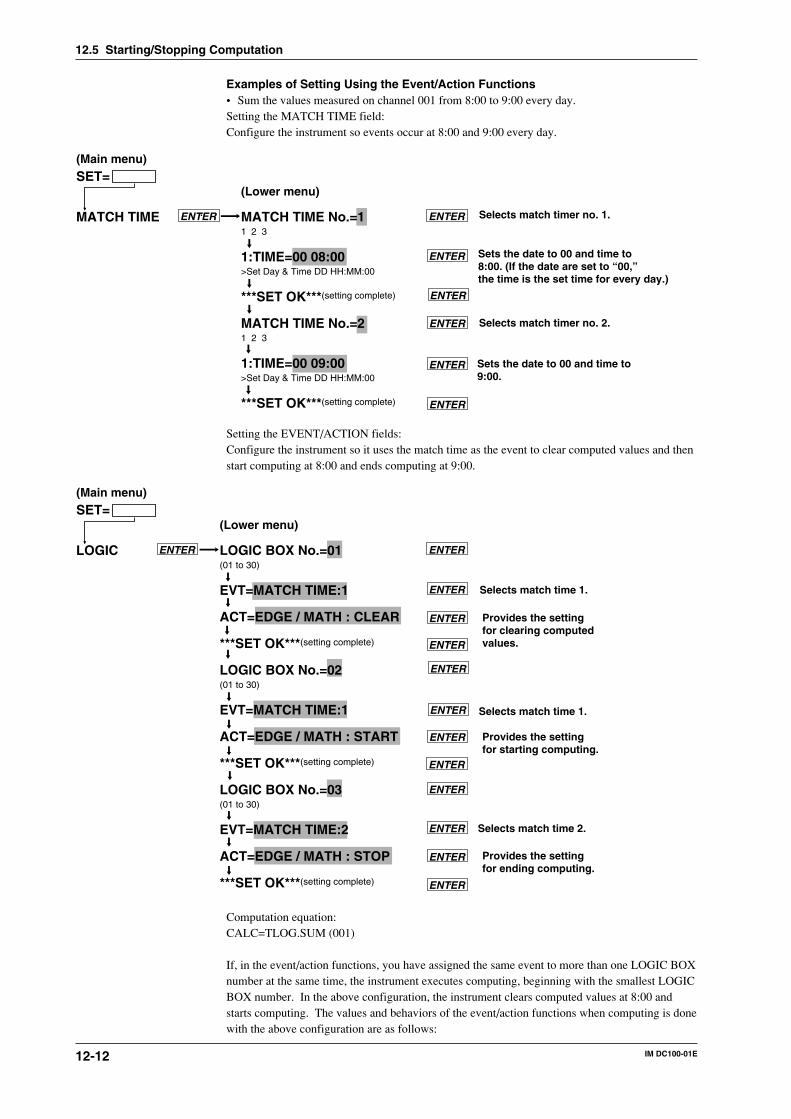
12-12 IM DC100-01E
Examples of Setting Using the Event/Action Functions• Sum the values measured on channel 001 from 8:00 to 9:00 every day.Setting the MATCH TIME field:Configure the instrument so events occur at 8:00 and 9:00 every day.
MATCH TIME No.=11 2 3
1:TIME=00 08:00>Set Day & Time DD HH:MM:00
***SET OK***(setting complete)
MATCH TIME No.=21 2 3
1:TIME=00 09:00>Set Day & Time DD HH:MM:00
***SET OK***(setting complete)
MATCH TIME ENTER ENTER
ENTER
SET=(Main menu)
(Lower menu)
ENTER
ENTER
ENTER
ENTER
Selects match timer no. 1.
Sets the date to 00 and time to8:00. (If the date are set to “00,” the time is the set time for every day.)
Selects match timer no. 2.
Sets the date to 00 and time to9:00.
Setting the EVENT/ACTION fields:Configure the instrument so it uses the match time as the event to clear computed values and thenstart computing at 8:00 and ends computing at 9:00.
ENTER LOGIC BOX No.=01(01 to 30)
EVT=MATCH TIME:1
ACT=EDGE / MATH : CLEAR
***SET OK***(setting complete)
LOGIC BOX No.=02(01 to 30)
EVT=MATCH TIME:1
ACT=EDGE / MATH : START
***SET OK***(setting complete)
LOGIC BOX No.=03(01 to 30)
EVT=MATCH TIME:2
ACT=EDGE / MATH : STOP
***SET OK***(setting complete)
LOGIC ENTER
ENTER
SET=(Main menu)
(Lower menu)
ENTER
ENTER
ENTER
ENTER
ENTER
ENTER
ENTER
ENTER
ENTER
ENTER
Selects match time 1.
Selects match time 1.
Selects match time 2.
Provides the setting for clearing computed values.
Provides the setting for starting computing.
Provides the setting for ending computing.
Computation equation:CALC=TLOG.SUM (001)
If, in the event/action functions, you have assigned the same event to more than one LOGIC BOXnumber at the same time, the instrument executes computing, beginning with the smallest LOGICBOX number. In the above configuration, the instrument clears computed values at 8:00 andstarts computing. The values and behaviors of the event/action functions when computing is donewith the above configuration are as follows:
12.5 Starting/Stopping Computation
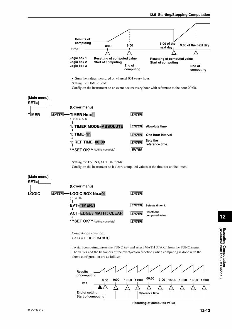
12-13IM DC100-01E
Execu
ting
Co
mp
utatio
n(A
vailable w
ith th
e /M1 M
od
el)
12
8:00 9:00 8:00 of thenext day
9:00 of the next day
Results ofcomputing
Resetting of computed valueStart of computing
Resetting of computed valueStart of computing
End ofcomputing
End ofcomputing
Time
Logic box 1Logic box 2Logic box 3
• Sum the values measured on channel 001 every hour.Setting the TIMER field:Configure the instrument so an event occurs every hour with reference to the hour 00:00.
TIMER No.=11 2 3 4 5 6
1: TIMER MODE=ABSOLUTE
1: TIME=1h
1: REF TIME=00:00
***SET OK***(setting complete)
TIMER ENTER ENTER
ENTER
SET=(Main menu)
(Lower menu)
ENTER
ENTER
ENTER
Absolute time
One-hour interval
Sets thereference time.
Setting the EVENT/ACTION fields:Configure the instrument so it clears computed values at the time set on the timer.
LOGIC BOX No.=01(01 to 30)
EVT=TIMER:1
ACT=EDGE / MATH : CLEAR
***SET OK***(setting complete)
LOGIC ENTER ENTER
ENTER
SET=(Main menu)
(Lower menu)
ENTER
ENTER
Selects timer 1.
Resets thecomputed value.
Computation equation:CALC=TLOG.SUM (001)
To start computing, press the FUNC key and select MATH START from the FUNC menu.The values and the behaviors of the event/action functions when computing is done with theabove configuration are as follows:
9:00 11:00
Resultsof computing
Resetting of computed value
Time
End of settingStart of computing
00:0010:008:00 13:00 14:00 15:00 16:00 17:00
Reference time
12.5 Starting/Stopping Computation
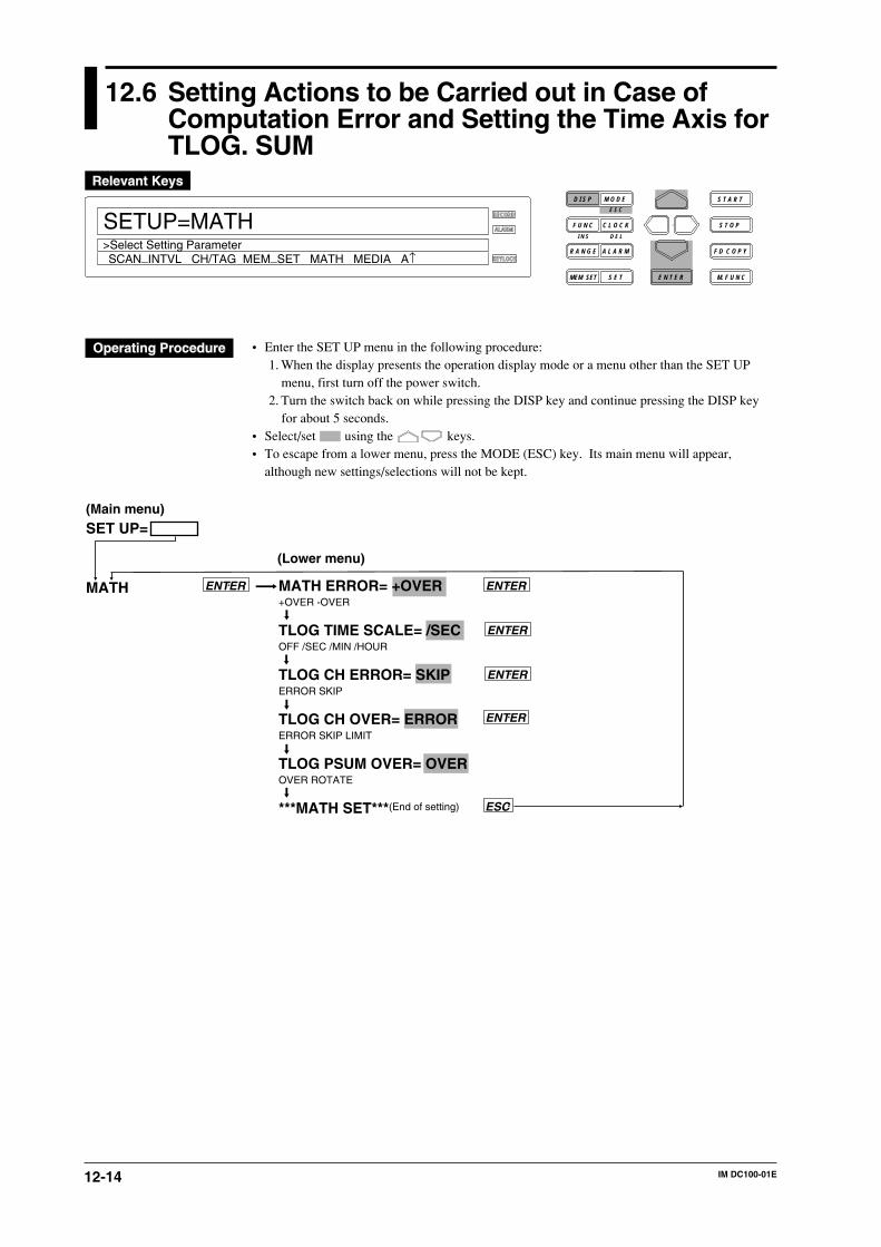
12-14 IM DC100-01E
12.6 Setting Actions to be Carried out in Case ofComputation Error and Setting the Time Axis forTLOG. SUM
RECORD
ALARM
KEYLOCK
SETUP=MATH
SCAN_INTVL CH/TAG MEM_SET MATH MEDIA A↑>Select Setting Parameter
D I S P M O D E
C L O C KF U N C
I N S D E L
R A N G E A L A R M
S E TMEM SET E N T E R
S T O P
F D C O P Y
M. F U N C
S T A R TE S C
• Enter the SET UP menu in the following procedure:1. When the display presents the operation display mode or a menu other than the SET UP
menu, first turn off the power switch.2. Turn the switch back on while pressing the DISP key and continue pressing the DISP key
for about 5 seconds.• Select/set using the keys.• To escape from a lower menu, press the MODE (ESC) key. Its main menu will appear,
although new settings/selections will not be kept.
ENTER
ENTER
MATH ERROR= +OVER+OVER -OVER
TLOG TIME SCALE= /SECOFF /SEC /MIN /HOUR
TLOG CH ERROR= SKIPERROR SKIP
TLOG CH OVER= ERRORERROR SKIP LIMIT
TLOG PSUM OVER= OVEROVER ROTATE
***MATH SET***(End of setting)
ENTER
SET UP=
MATH
ESC
(Main menu)
(Lower menu)
ENTER
ENTER
12-15IM DC100-01E
Execu
ting
Co
mp
utatio
n(A
vailable w
ith th
e /M1 M
od
el)
12
Displaying in case of computation error (MATH ERROR)Used to determine whether +OVER or -OVER be displayed/saved in case of computation error.
Time axis scale for TLOG SUM (TLOG TIME SCALE)For TLOG.SUM of time series, data is added at each measurement interval. However, in the caseof an input having unit of /s, /min or /h like flow rate, the computation result will differ from theactual value, if addition of data is carried out. In this case, setting TLOG TIME SCALEaccording to the unit of the input will cause the data measured at measurement intervals to beprocessed according to the unit of the input.
For instance, if the measurement interval is 2s and input value is 100 m3/min, the computationresult will be 30000 after the elapse of one minute, since 100 is added every 2 seconds. SettingTLOG TIME SCALE to /min will cause the measured data to be multiplied by 2s/60s at eachmeasurement interval, thus making the result close to the actual input value.If this function is set to OFF, simple addition of data will be carried out.
Process of abnormal data during TLOG or CLOG (TLOG CH ERROR)Used to select the process method for abnormal data obtained during TLOG or CLOG.• ERROR : Abnormal data is processed as a computation error.• SKIP : Abnormal data is ignored and computation is continued.
Process of overflow data during TLOG or CLOG (TLOG CH OVER)Used to select the process method for overflow data obtained during TLOG or CLOG.• ERROR : Overflow data is processed as a computation error.• SKIP : Overflow data is ignored and computation is continued.• LIMIT : Overflow data is treated as the next data for computation.
Measurement channels to which linear scaling is applied: Specified scaling upper-/lower-limitMeasurement channels to which no linear scaling is applied: Upper-/lower-limit of themeasuring rangeComputation channels: Specified LEFT/RIGHT value
Processing of the results of TLOG.PSUM computation (for pulse input)• OVER: If the result of a separate calculation of TLOG.PSUM (XXXX) exceeds 99999999, the
instrument goes into an overflow.• ROTATE: If the result of a separate calculation of TLOG.PSUM (XXXX) exceeds 99999999,
the instrument resets the value subsequent to 99999999 to 0 and continues computing. Forexample, if the measured data subsequent to 99999999 which has been reached is 3, thecomputed result becomes “2” by counting 0, 1 and 2.
The process is effective only when a pulse input module is installed.
12.6 Setting Actions to be Carried out in Case of Computation Error and Setting the Time Axis for TLOG. SUM
13-1IM DC100-01E
Tro
ub
le-sho
otin
g an
d M
ainten
ance
13
13.1 Periodic Maintenance and Recommended PartsReplacement Period
Periodic maintenanceCheck the instrument’s operation periodically to keep it in good operating condition. Especiallycheck the following items and replace consumable parts as needed. Do not use a lubricant forperiodic maintenance.
• Are display and data saving functioning properly?
If problems develop with the instrument, see Section 13.3, “Troubleshooting.”
Recommended parts replacement periodIt is necessary that the instrument’s parts be replaced periodically for use of the instrument overan extended period of time. The table below shows the recommended parts replacement periodsfor specific parts that wear out. These replacement periods indicate where the instruments havebeen used under normal operating conditions. When replacing parts, refer to these replacementperiods taking the actual operating conditions into consideration. When replacing parts other thanfuse, please contact your nearest Sales representative. Addresses may be found on the back coverof this manual.
Part Part number Replacement Descriptionperiod (in years)
Display B9233KJ 3.4 30,000 hours
Fuse A1350EF 2 For AC power supply (2.5A, time-lag fuse)A1354EF 2 For DC power supply (6.3A, time-lag fuse)
Lithium battery B9234XZ 10 For backup of information that has been set
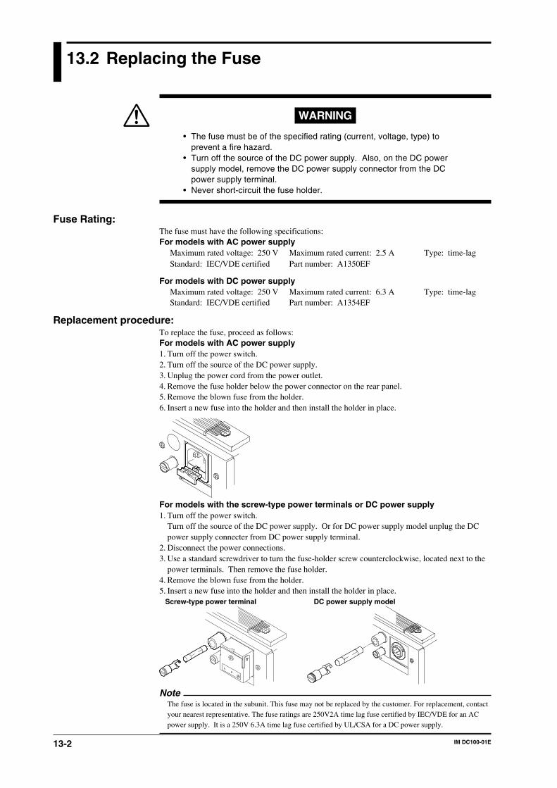
13-2 IM DC100-01E
13.2 Replacing the Fuse
WARNING
• The fuse must be of the specified rating (current, voltage, type) toprevent a fire hazard.
• Turn off the source of the DC power supply. Also, on the DC powersupply model, remove the DC power supply connector from the DCpower supply terminal.
• Never short-circuit the fuse holder.
Fuse Rating:The fuse must have the following specifications:For models with AC power supply
Maximum rated voltage: 250 V Maximum rated current: 2.5 A Type: time-lagStandard: IEC/VDE certified Part number: A1350EF
For models with DC power supplyMaximum rated voltage: 250 V Maximum rated current: 6.3 A Type: time-lagStandard: IEC/VDE certified Part number: A1354EF
Replacement procedure:To replace the fuse, proceed as follows:For models with AC power supply1. Turn off the power switch.2. Turn off the source of the DC power supply.3. Unplug the power cord from the power outlet.4. Remove the fuse holder below the power connector on the rear panel.5. Remove the blown fuse from the holder.6. Insert a new fuse into the holder and then install the holder in place.
For models with the screw-type power terminals or DC power supply1. Turn off the power switch.
Turn off the source of the DC power supply. Or for DC power supply model unplug the DCpower supply connecter from DC power supply terminal.
2. Disconnect the power connections.3. Use a standard screwdriver to turn the fuse-holder screw counterclockwise, located next to the
power terminals. Then remove the fuse holder.4. Remove the blown fuse from the holder.5. Insert a new fuse into the holder and then install the holder in place.
Screw-type power terminal DC power supply model
NoteThe fuse is located in the subunit. This fuse may not be replaced by the customer. For replacement, contactyour nearest representative. The fuse ratings are 250V2A time lag fuse certified by IEC/VDE for an ACpower supply. It is a 250V 6.3A time lag fuse certified by UL/CSA for a DC power supply.
13-3IM DC100-01E
Tro
ub
le-sho
otin
g an
d M
ainten
ance
13
13.3 Troubleshooting
If an error code appears on the display, see Section 13.4, “Error Codes.”If servicing is necessary, or if the instrument is not operating correctly though the followingcorrective actions have been taken, please contact Yokogawa Engineering Service Corporation.Addresses may be found on the back cover of this manual.
Problem Probable Cause Corrective Action
Collector does not operate. Power switch is off. Turn on the power.
Power supply is not Connect properly.connected properly.
Supplied power does not Use power meeting its requirements.meet power requirements.
Fuse blown. Replace fuse. (If the fuse blows immediately after turning on thepower, servicing will be required.)
Output beyond its limits Input specifications are not Correct input specifications.Fluctuating indication. correct.
Incorrect measuring range or Change measuring range or span.span
Noise superimposed. Connect input wiring far away from noise source.
Ground collector.
Ground measurement object.
Isolate thermocouple from measurement object.
Use shielded wiring for input line.
Change A/D integral times.
Use moving average.
Use input filter.
No countermeasure taken Install input terminal cover properly.against ambient temperature
Protect collector from blowing air of fan.changes.
Keep temperature changes near input terminals small.
Input connected improperly. Connect input properly.
Connect module properly.
Tighten screws properly.
Isolate RTD from ground.
Replace disconnected thermocouples.
Collector connected in parallel Do not use burnout functions in other instruments.with other instruments.
Ground collector and other instruments in the same ground line.
Do not connect collector in parallel with other instruments(for use with dual-element TC).
RJC set improperly Set RJC properly.(for TC input)
Other cause. Contact Yokogawa Engineering Service.
Defective display Noise superimposed. Lay input wiring far away from noise source.
Ground collector.
Ground measurement object.
Isolate TC from measurement object.
Use shielded wires for input line.
Change A/D integration times.
Use input filter.
Data indicates “xxxxxx” Input module connected Connect input properly.improperly
Collector does not work even with Keylock not released. Disable keylock functions in setup mode.operation key pressed.
Collector set in remote mode. Set collector in local mode.
Other cause. Contact Yokogawa Engineering Service.
Setting cannot be operated. A module is not connected Connect properly.properly.
The extension cable is not Connect properly.connected properly.
There is no system recognition. Execute the system structuring menu.
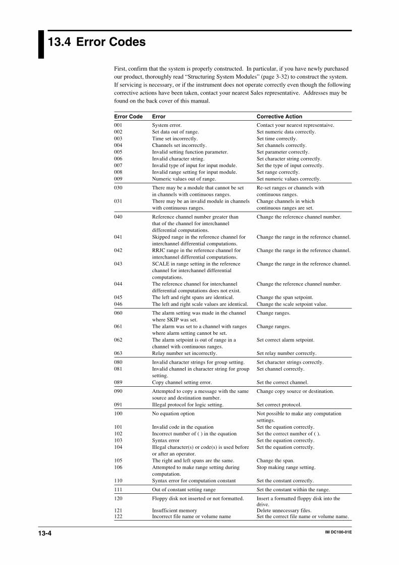
13-4 IM DC100-01E
13.4 Error Codes
First, confirm that the system is properly constructed. In particular, if you have newly purchasedour product, thoroughly read “Structuring System Modules” (page 3-32) to construct the system.If servicing is necessary, or if the instrument does not operate correctly even though the followingcorrective actions have been taken, contact your nearest Sales representative. Addresses may befound on the back cover of this manual.
Error Code Error Corrective Action
001 System error. Contact your nearest representaive.002 Set data out of range. Set numeric data correctly.003 Time set incorrectly. Set time correctly.004 Channels set incorrectly. Set channels correctly.005 Invalid setting function parameter. Set parameter correctly.006 Invalid character string. Set character string correctly.007 Invalid type of input for input module. Set the type of input correctly.008 Invalid range setting for input module. Set range correctly.009 Numeric values out of range. Set numeric values correctly.
030 There may be a module that cannot be set Re-set ranges or channels within channels with continuous ranges. continuous ranges.
031 There may be an invalid module in channels Change channels in whichwith continuous ranges. continuous ranges are set.
040 Reference channel number greater than Change the reference channel number.that of the channel for interchanneldifferential computations.
041 Skipped range in the reference channel for Change the range in the reference channel.interchannel differential computations.
042 RRJC range in the reference channel for Change the range in the reference channel.interchannel differential computations.
043 SCALE in range setting in the reference Change the range in the reference channel.channel for interchannel differentialcomputations.
044 The reference channel for interchannel Change the reference channel number.differential computations does not exist.
045 The left and right spans are identical. Change the span setpoint.046 The left and right scale values are identical. Change the scale setpoint value.
060 The alarm setting was made in the channel Change ranges.where SKIP was set.
061 The alarm was set to a channel with ranges Change ranges.where alarm setting cannot be set.
062 The alarm setpoint is out of range in a Set correct alarm setpoint.channel with continuous ranges.
063 Relay number set incorrectly. Set relay number correctly.
080 Invalid character strings for group setting. Set character strings correctly.081 Invalid channel in character string for group Set channel correctly.
setting.089 Copy channel setting error. Set the correct channel.
090 Attempted to copy a message with the same Change copy source or destination.source and destination number.
091 Illegal protocol for logic setting. Set correct protocol.
100 No equation option Not possible to make any computationsettings.
101 Invalid code in the equation Set the equation correctly.102 Incorrect number of ( ) in the equation Set the correct number of ( ).103 Syntax error Set the equation correctly.104 Illegal character(s) or code(s) is used before Set the equation correctly.
or after an operator.105 The right and left spans are the same. Change the span.106 Attempted to make range setting during Stop making range setting.
computation.110 Syntax error for computation constant Set the constant correctly.
111 Out of constant setting range Set the constant within the range.
120 Floppy disk not inserted or not formatted. Insert a formatted floppy disk into thedrive.
121 Insufficient memory Delete unnecessary files.122 Incorrect file name or volume name Set the correct file name or volume name.
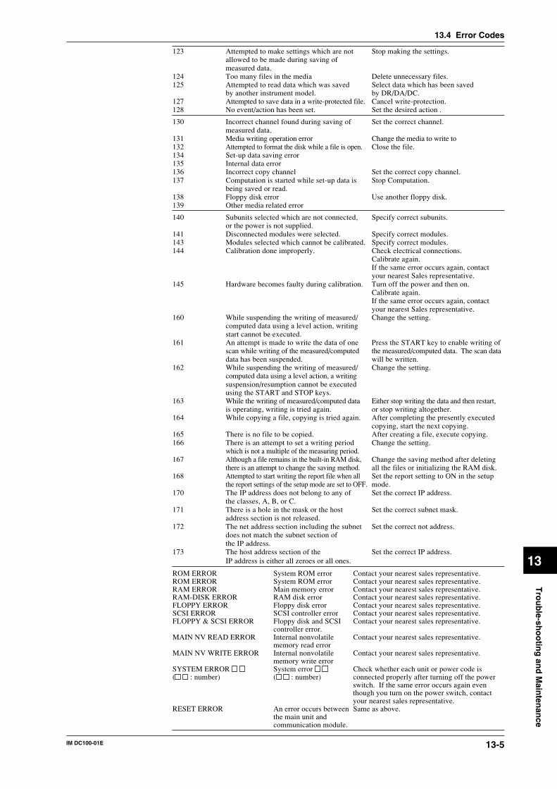
13-5IM DC100-01E
Tro
ub
le-sho
otin
g an
d M
ainten
ance
13
13.4 Error Codes
123 Attempted to make settings which are not Stop making the settings.allowed to be made during saving ofmeasured data.
124 Too many files in the media Delete unnecessary files.125 Attempted to read data which was saved Select data which has been saved
by another instrument model. by DR/DA/DC.127 Attempted to save data in a write-protected file. Cancel write-protection.128 No event/action has been set. Set the desired action .
130 Incorrect channel found during saving of Set the correct channel.measured data.
131 Media writing operation error Change the media to write to132 Attempted to format the disk while a file is open. Close the file.134 Set-up data saving error135 Internal data error136 Incorrect copy channel Set the correct copy channel.137 Computation is started while set-up data is Stop Computation.
being saved or read.138 Floppy disk error Use another floppy disk.139 Other media related error
140 Subunits selected which are not connected, Specify correct subunits.or the power is not supplied.
141 Disconnected modules were selected. Specify correct modules.143 Modules selected which cannot be calibrated. Specify correct modules.144 Calibration done improperly. Check electrical connections.
Calibrate again.If the same error occurs again, contactyour nearest Sales representative.
145 Hardware becomes faulty during calibration. Turn off the power and then on.Calibrate again.If the same error occurs again, contactyour nearest Sales representative.
160 While suspending the writing of measured/ Change the setting.computed data using a level action, writingstart cannot be executed.
161 An attempt is made to write the data of one Press the START key to enable writing ofscan while writing of the measured/computed the measured/computed data. The scan datadata has been suspended. will be written.
162 While suspending the writing of measured/ Change the setting.computed data using a level action, a writingsuspension/resumption cannot be executedusing the START and STOP keys.
163 While the writing of measured/computed data Either stop writing the data and then restart,is operating, writing is tried again. or stop writing altogether.
164 While copying a file, copying is tried again. After completing the presently executedcopying, start the next copying.
165 There is no file to be copied. After creating a file, execute copying.166 There is an attempt to set a writing period Change the setting.
which is not a multiple of the measuring period.167 Although a file remains in the built-in RAM disk, Change the saving method after deleting
there is an attempt to change the saving method. all the files or initializing the RAM disk.168 Attempted to start writing the report file when all Set the report setting to ON in the setup
the report settings of the setup mode are set to OFF. mode.170 The IP address does not belong to any of Set the correct IP address.
the classes, A, B, or C.171 There is a hole in the mask or the host Set the correct subnet mask.
address section is not released.172 The net address section including the subnet Set the correct not address.
does not match the subnet section ofthe IP address.
173 The host address section of the Set the correct IP address.IP address is either all zeroes or all ones.
ROM ERROR System ROM error Contact your nearest sales representative.ROM ERROR System ROM error Contact your nearest sales representative.RAM ERROR Main memory error Contact your nearest sales representative.RAM-DISK ERROR RAM disk error Contact your nearest sales representative.FLOPPY ERROR Floppy disk error Contact your nearest sales representative.SCSI ERROR SCSI controller error Contact your nearest sales representative.FLOPPY & SCSI ERROR Floppy disk and SCSI Contact your nearest sales representative.
controller error.MAIN NV READ ERROR Internal nonvolatile Contact your nearest sales representative.
memory read errorMAIN NV WRITE ERROR Internal nonvolatile Contact your nearest sales representative.
memory write errorSYSTEM ERROR System error Check whether each unit or power code is( : number) ( : number) connected properly after turning off the power
switch. If the same error occurs again eventhough you turn on the power switch, contactyour nearest sales representative.
RESET ERROR An error occurs between Same as above.the main unit andcommunication module.
13-6 IM DC100-01E
13.5 Calibration
OverviewWe recommend that you calibrate the DC100 at least once a year to assure its measurementaccuracy. When calibrating, please contact your nearest Sales representative at its address on theback cover of this manual.Press and hold the MODE key and then turn on the power switch to place the instrument in thecalibration mode. Select the subunit and module to calibrate the instrument on a module basis.After completing the calibration, turn off the power and then turn it back on when resuming themeasurements.
CAUTION
You can use the DISPLAY mode only for a calibration adjustment. If it is maladjusted, the instrument maybecome faulty. For details, please contact your nearest Sales representative.
Calibration needs selection of:• a subunit and module and;• the calibration mode.Once the subunit and module have been selected, they are no longer selected again as long as thecalibration END mode is not executed.
Input modules to be calibrated• Universal input module• DCV/TC/DI input module• mA-input module• Strain input module• Retransmission module
Calibration mode• CAL/EXEC mode: This mode enables specified ranges to be calibrated.• DISPLAY mode: This mode enables current calibrated values to be displayed.• END mode: This mode enables calibrated values to be stored in the internal nonvolatile
memory and terminates the calibration mode. (If ABORT is selected, the calibrated values arenot stored in memory.)
Subunit/module selection errorThe following error messages are displayed:• The specified subunit remains disconnected. Or the power supply is not turned on (ERROR 140).• The specified module remains disconnected (ERROR141).• The specified module is such that it cannot be calibrated (ERROR143).
Calibrated data errorThe following error messages are displayed:• Attempted to remove the module during calibration. Or hardware error: ERROR145• Invalid calibrated data: ERROR144• Attempted to set invalid numeric values in the DISPLAY mode: ERROR145
NoteWhen a calibrated data error appears, the error data are stored in memory.
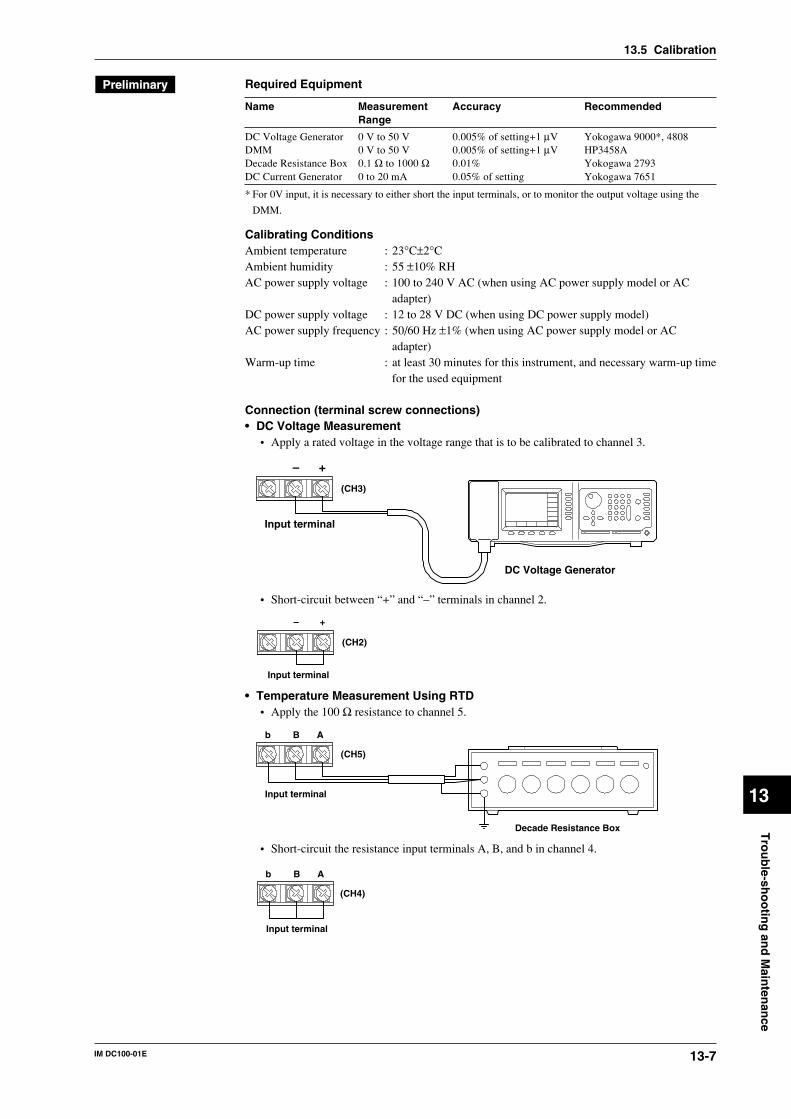
13-7IM DC100-01E
Tro
ub
le-sho
otin
g an
d M
ainten
ance
13
Required Equipment
Name Measurement Accuracy RecommendedRange
DC Voltage Generator 0 V to 50 V 0.005% of setting+1 µV Yokogawa 9000*, 4808DMM 0 V to 50 V 0.005% of setting+1 µV HP3458ADecade Resistance Box 0.1 Ω to 1000 Ω 0.01% Yokogawa 2793DC Current Generator 0 to 20 mA 0.05% of setting Yokogawa 7651
* For 0V input, it is necessary to either short the input terminals, or to monitor the output voltage using the
DMM.
Calibrating ConditionsAmbient temperature : 23°C±2°CAmbient humidity : 55 ±10% RHAC power supply voltage : 100 to 240 V AC (when using AC power supply model or AC
adapter)DC power supply voltage : 12 to 28 V DC (when using DC power supply model)AC power supply frequency : 50/60 Hz ±1% (when using AC power supply model or AC
adapter)Warm-up time : at least 30 minutes for this instrument, and necessary warm-up time
for the used equipment
Connection (terminal screw connections)• DC Voltage Measurement
• Apply a rated voltage in the voltage range that is to be calibrated to channel 3.
+–
DC Voltage Generator
Input terminal
(CH3)
• Short-circuit between “+” and “–” terminals in channel 2.
+–
Input terminal
(CH2)
• Temperature Measurement Using RTD• Apply the 100 Ω resistance to channel 5.
Bb A
Decade Resistance Box
Input terminal
(CH5)
• Short-circuit the resistance input terminals A, B, and b in channel 4.
Bb A
Input terminal
(CH4)
13.5 Calibration
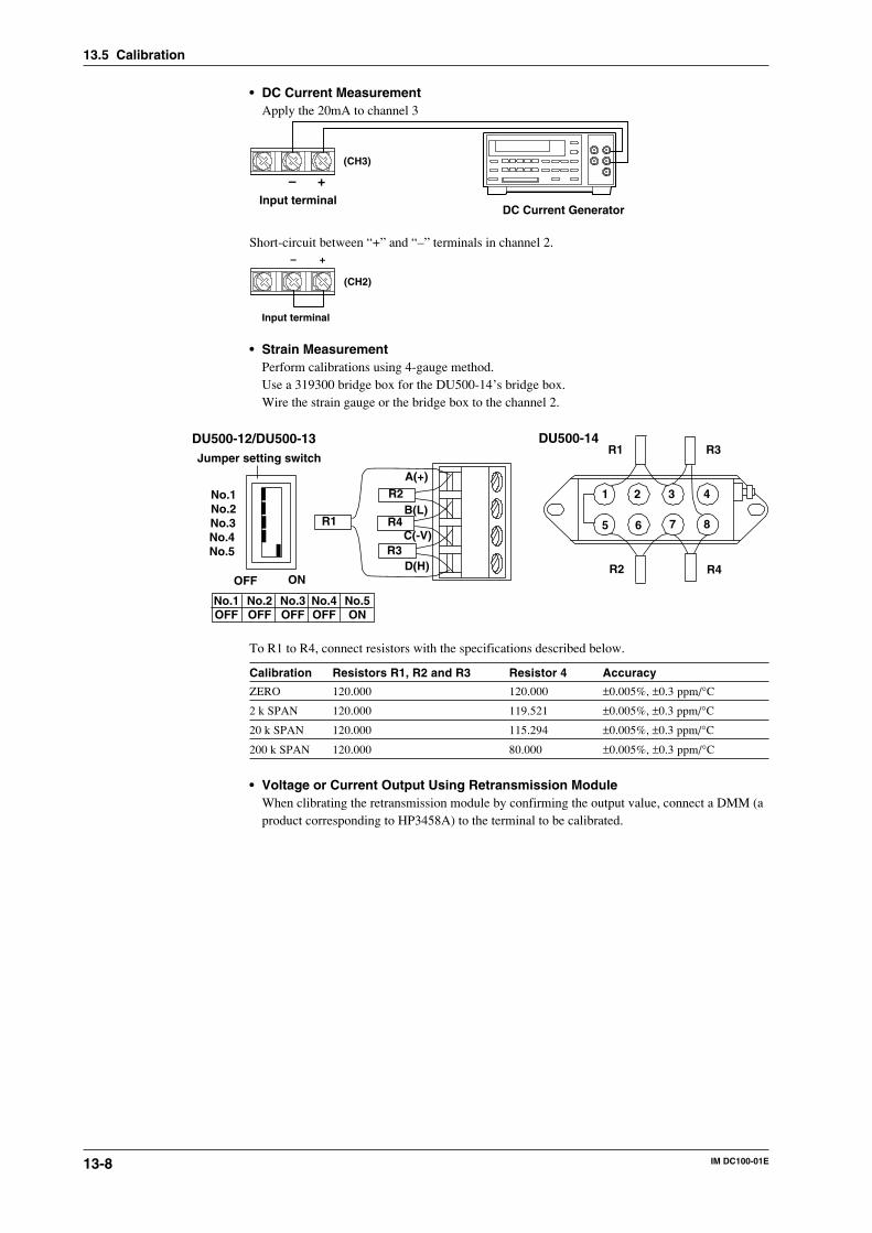
13-8 IM DC100-01E
• DC Current MeasurementApply the 20mA to channel 3
+–Input terminal
(CH3)
DC Current Generator
Short-circuit between “+” and “–” terminals in channel 2.+–
Input terminal
(CH2)
• Strain MeasurementPerform calibrations using 4-gauge method.Use a 319300 bridge box for the DU500-14’s bridge box.Wire the strain gauge or the bridge box to the channel 2.
Jumper setting switch
ONOFF
No.1No.2No.3No.4No.5
A(+)
B(L)
C(-V)
D(H)
DU500-12/DU500-13 DU500-14
No.1OFF
No.2OFF
No.3OFF
No.4OFF
No.5ON
1 2 3 4
5 6 7 8
R4R2
R3R1
R2
R4
R3
R1
To R1 to R4, connect resistors with the specifications described below.
Calibration Resistors R1, R2 and R3 Resistor 4 Accuracy
ZERO 120.000 120.000 ±0.005%, ±0.3 ppm/°C
2 k SPAN 120.000 119.521 ±0.005%, ±0.3 ppm/°C
20 k SPAN 120.000 115.294 ±0.005%, ±0.3 ppm/°C
200 k SPAN 120.000 80.000 ±0.005%, ±0.3 ppm/°C
• Voltage or Current Output Using Retransmission ModuleWhen clibrating the retransmission module by confirming the output value, connect a DMM (aproduct corresponding to HP3458A) to the terminal to be calibrated.
13.5 Calibration
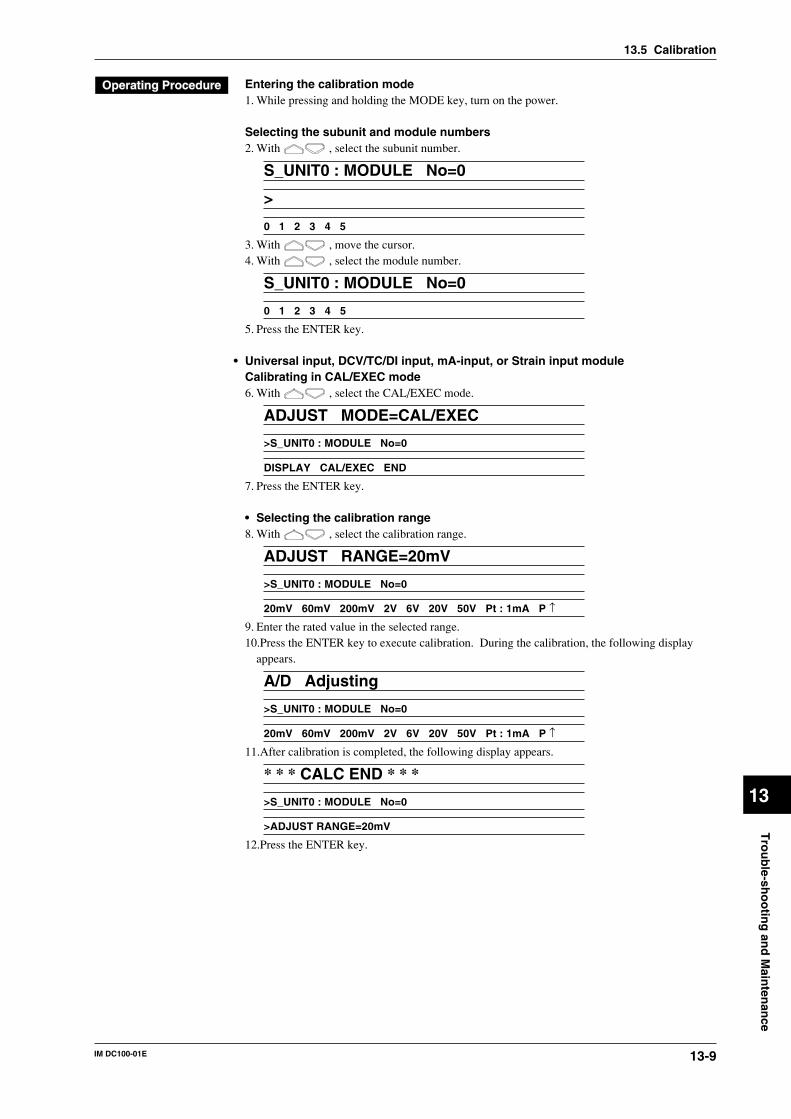
13-9IM DC100-01E
Tro
ub
le-sho
otin
g an
d M
ainten
ance
13
Entering the calibration mode1. While pressing and holding the MODE key, turn on the power.
Selecting the subunit and module numbers2. With , select the subunit number.
S_UNIT0 : MODULE No=0
>
0 1 2 3 4 5
3. With , move the cursor.4. With , select the module number.
S_UNIT0 : MODULE No=0
0 1 2 3 4 5
5. Press the ENTER key.
• Universal input, DCV/TC/DI input, mA-input, or Strain input moduleCalibrating in CAL/EXEC mode6. With , select the CAL/EXEC mode.
ADJUST MODE=CAL/EXEC
>S_UNIT0 : MODULE No=0
DISPLAY CAL/EXEC END
7. Press the ENTER key.
• Selecting the calibration range8. With , select the calibration range.
ADJUST RANGE=20mV
>S_UNIT0 : MODULE No=0
20mV 60mV 200mV 2V 6V 20V 50V Pt : 1mA P ↑
9. Enter the rated value in the selected range.10.Press the ENTER key to execute calibration. During the calibration, the following display
appears.
A/D Adjusting
>S_UNIT0 : MODULE No=0
20mV 60mV 200mV 2V 6V 20V 50V Pt : 1mA P ↑
11.After calibration is completed, the following display appears.
* * * CALC END * * *
>S_UNIT0 : MODULE No=0
>ADJUST RANGE=20mV
12.Press the ENTER key.
13.5 Calibration
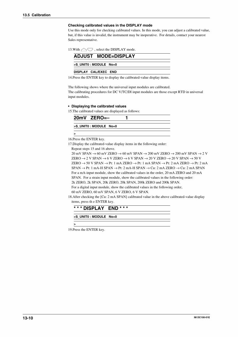
13-10 IM DC100-01E
Checking calibrated values in the DISPLAY modeUse this mode only for checking calibrated values. In this mode, you can adjust a calibrated value,but, if this value is invalid, the instrument may be inoperative. For details, contact your nearestSales representative.
13.With , select the DISPLAY mode.
ADJUST MODE=DISPLAY
>S_UNIT0 : MODULE No=0
DISPLAY CAL/EXEC END
14.Press the ENTER key to display the calibrated-value display items.
The following shows where the universal input modules are calibrated.The calibrating procedures for DC V/TC/DI input modules are those except RTD in universalinput modules.
• Displaying the calibrated values15.The calibrated values are displayed as follows:
20mV ZERO=– 1
>S_UNIT0 : MODULE No=0
>
16.Press the ENTER key.17.Display the calibrated-value display items in the following order:
Repeat steps 15 and 16 above.20 mV SPAN → 60 mV ZERO → 60 mV SPAN → 200 mV ZERO → 200 mV SPAN → 2 VZERO → 2 V SPAN → 6 V ZERO → 6 V SPAN → 20 V ZERO → 20 V SPAN → 50 VZERO → 50 V SPAN → Pt: 1 mA ZERO → Pt: 1 mA SPAN → Pt: 2 mA ZERO → Pt: 2 mASPAN → Pt: 1 mA-H SPAN → Pt: 2 mA-H SPAN → Cu: 2 mA ZERO → Cu: 2 mA SPANFor a mA-input module, show the calibrated values in the order, 20 mA ZERO and 20 mASPAN. For a strain input module, show the calibrated values in the following order:2k ZERO, 2k SPAN, 20k ZERO, 20k SPAN, 200k ZERO and 200k SPAN.For a digital input module, show the calibrated values in the following order,60 mV ZERO, 60 mV SPAN, 6 V ZERO, 6 V SPAN.
18.After checking the [Cu: 2 mA SPAN] calibrated value in the above calibrated-value displayitems, press th e ENTER key.
* * * DISPLAY END * * *
>S_UNIT0 : MODULE No=0
>
19.Press the ENTER key.
13.5 Calibration
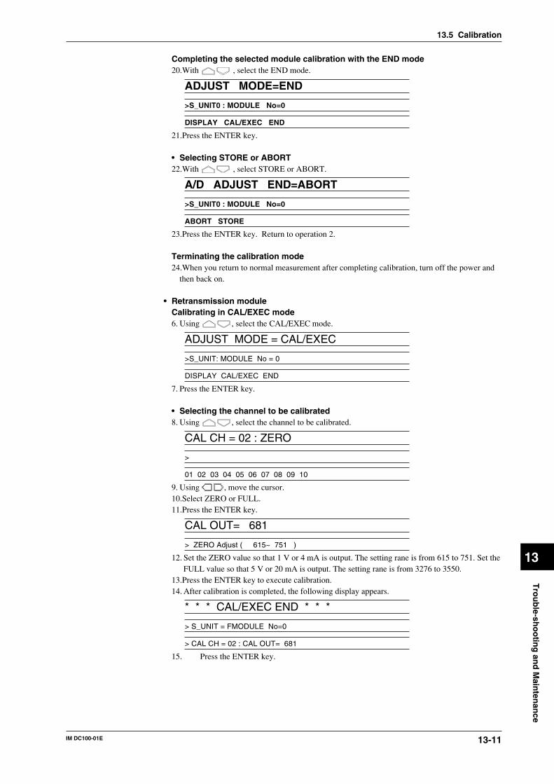
13-11IM DC100-01E
Tro
ub
le-sho
otin
g an
d M
ainten
ance
13
13.5 Calibration
Completing the selected module calibration with the END mode20.With , select the END mode.
ADJUST MODE=END
>S_UNIT0 : MODULE No=0
DISPLAY CAL/EXEC END
21.Press the ENTER key.
• Selecting STORE or ABORT22.With , select STORE or ABORT.
A/D ADJUST END=ABORT
>S_UNIT0 : MODULE No=0
ABORT STORE
23.Press the ENTER key. Return to operation 2.
Terminating the calibration mode24.When you return to normal measurement after completing calibration, turn off the power and
then back on.
• Retransmission moduleCalibrating in CAL/EXEC mode6. Using , select the CAL/EXEC mode.
ADJUST MODE = CAL/EXEC
>S_UNIT: MODULE No = 0
DISPLAY CAL/EXEC END
7. Press the ENTER key.
• Selecting the channel to be calibrated8. Using , select the channel to be calibrated.
CAL CH = 02 : ZERO
>
01 02 03 04 05 06 07 08 09 10
9. Using , move the cursor.10.Select ZERO or FULL.11.Press the ENTER key.
CAL OUT= 681
> ZERO Adjust ( 615~ 751 )
12. Set the ZERO value so that 1 V or 4 mA is output. The setting rane is from 615 to 751. Set theFULL value so that 5 V or 20 mA is output. The setting rane is from 3276 to 3550.
13.Press the ENTER key to execute calibration.14. After calibration is completed, the following display appears.
* * * CAL/EXEC END * * *
> S_UNIT = FMODULE No=0
> CAL CH = 02 : CAL OUT= 681
15. Press the ENTER key.
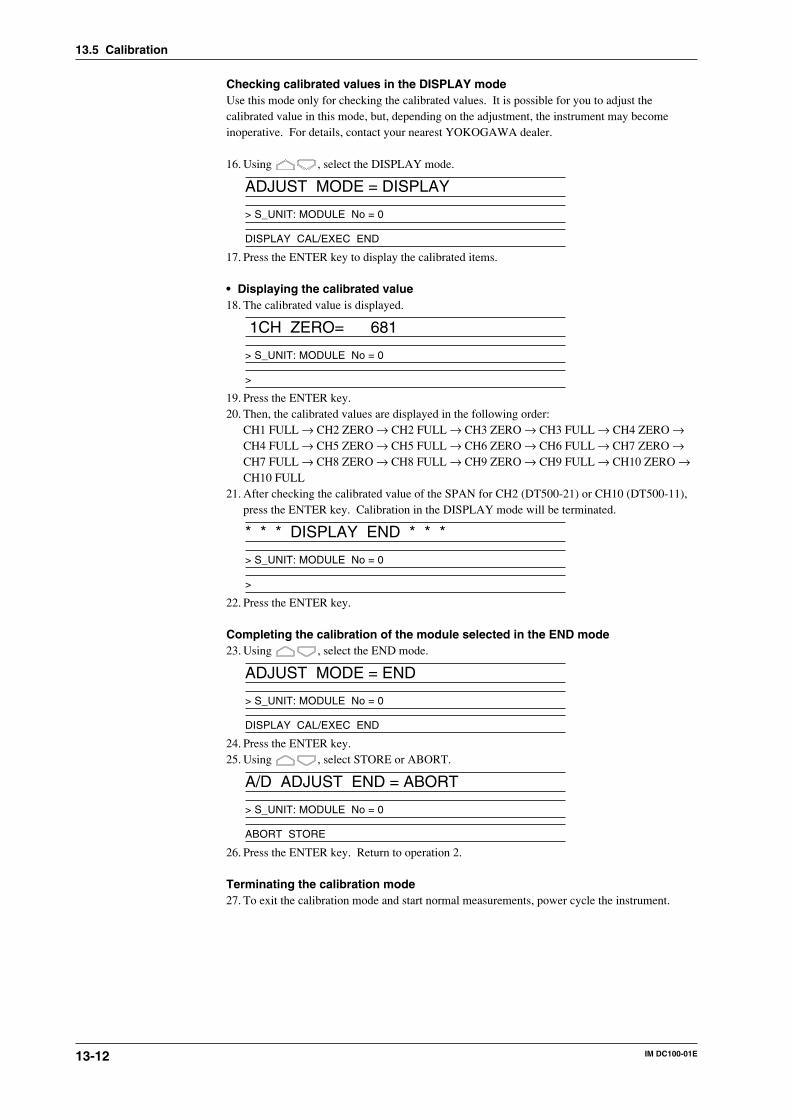
13-12 IM DC100-01E
Checking calibrated values in the DISPLAY modeUse this mode only for checking the calibrated values. It is possible for you to adjust thecalibrated value in this mode, but, depending on the adjustment, the instrument may becomeinoperative. For details, contact your nearest YOKOGAWA dealer.
16. Using , select the DISPLAY mode.
ADJUST MODE = DISPLAY
> S_UNIT: MODULE No = 0
DISPLAY CAL/EXEC END
17. Press the ENTER key to display the calibrated items.
• Displaying the calibrated value18. The calibrated value is displayed.
1CH ZERO= 681
> S_UNIT: MODULE No = 0
>
19. Press the ENTER key.20. Then, the calibrated values are displayed in the following order:
CH1 FULL → CH2 ZERO → CH2 FULL → CH3 ZERO → CH3 FULL → CH4 ZERO →CH4 FULL → CH5 ZERO → CH5 FULL → CH6 ZERO → CH6 FULL → CH7 ZERO →CH7 FULL → CH8 ZERO → CH8 FULL → CH9 ZERO → CH9 FULL → CH10 ZERO →CH10 FULL
21. After checking the calibrated value of the SPAN for CH2 (DT500-21) or CH10 (DT500-11),press the ENTER key. Calibration in the DISPLAY mode will be terminated.
* * * DISPLAY END * * *
> S_UNIT: MODULE No = 0
>
22. Press the ENTER key.
Completing the calibration of the module selected in the END mode23. Using , select the END mode.
ADJUST MODE = END
> S_UNIT: MODULE No = 0
DISPLAY CAL/EXEC END
24. Press the ENTER key.25. Using , select STORE or ABORT.
A/D ADJUST END = ABORT
> S_UNIT: MODULE No = 0
ABORT STORE
26. Press the ENTER key. Return to operation 2.
Terminating the calibration mode27. To exit the calibration mode and start normal measurements, power cycle the instrument.
13.5 Calibration
13-13IM DC100-01E
Tro
ub
le-sho
otin
g an
d M
ainten
ance
13
CAL/EXEC mode (for calibration of a specifie range)• Items for calibration range
• Items for the calibration range vary depending on the type of module to be calibrated.• For use with universal input modules, select the items for the calibration range from among
the following:20 mV/60 mV/200 mV/2 V/6 V/20 V/50 V/Pt: 1 mA/Pt: 2 mA/Pt: 1 mA-H/Pt: 2 mA-H/Cu:2 mA
• When the DC V/TC/DI input module is selected, RTD in the universal input module is notdisplayed.
• The choice is 20 mA only for mA-input modules.• For strain input modules, select from 2 k, 20 k, 200 k and INIT.
INIT: Set defaults in the A/D Adjustment section. Calibration is necessary, however, afterexecution.
• For digital input modules select form 60 mV and 6 V.
• Displaying error messagesThe following error messages are displayed.• Attempted to remove the module during calibration. Or, hardware error: ERROR145• Invalid calibrated data: ERROR144• Error generation in initial balance when making adjustments: ERROR146
Note• When calibrating a high-precision RTD (Pt: [ ]-H), do so after calibrating the voltages to maintain
accuracy.• When a calibrated data error appears, the error data are stored in memory.• If ERROR145 appears, turn off the power and then back on to restart operation. If the same error occurs
again, the recorder may be defective.• If ERROR144 or 146 appears, check the electrical connections and input data. If the same error occurs
again, the module to be calibrated may be defective.• When calibrating a strain input module, first calibrate zero (ZERO) and then the span (SPAN).
13.5 Calibration
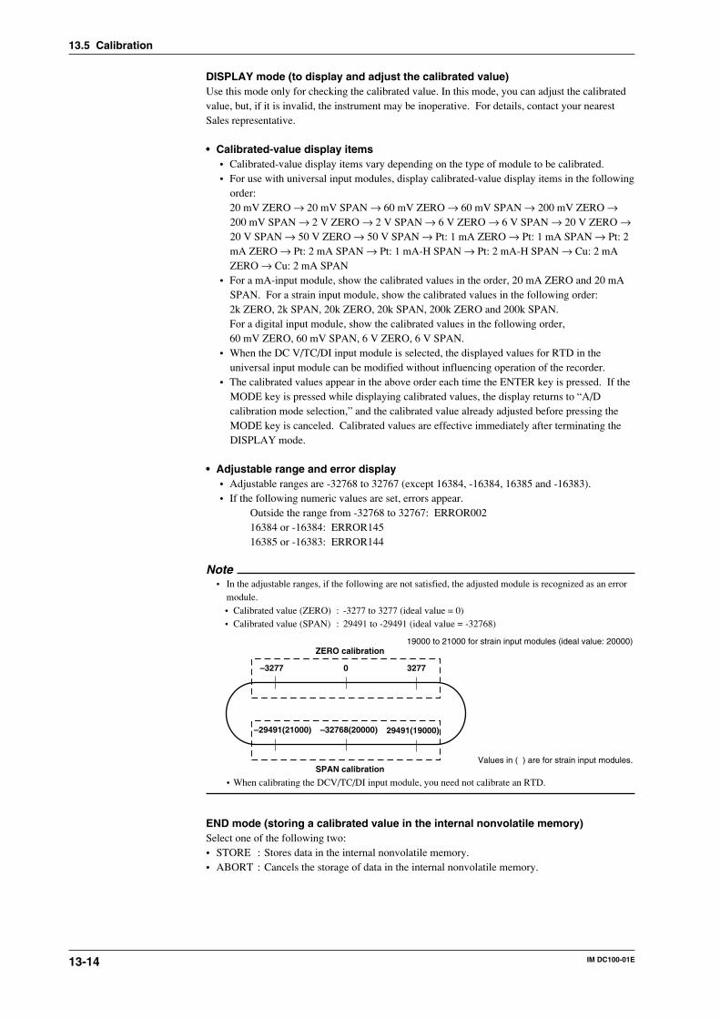
13-14 IM DC100-01E
DISPLAY mode (to display and adjust the calibrated value)Use this mode only for checking the calibrated value. In this mode, you can adjust the calibratedvalue, but, if it is invalid, the instrument may be inoperative. For details, contact your nearestSales representative.
• Calibrated-value display items• Calibrated-value display items vary depending on the type of module to be calibrated.• For use with universal input modules, display calibrated-value display items in the following
order:20 mV ZERO → 20 mV SPAN → 60 mV ZERO → 60 mV SPAN → 200 mV ZERO →200 mV SPAN → 2 V ZERO → 2 V SPAN → 6 V ZERO → 6 V SPAN → 20 V ZERO →20 V SPAN → 50 V ZERO → 50 V SPAN → Pt: 1 mA ZERO → Pt: 1 mA SPAN → Pt: 2mA ZERO → Pt: 2 mA SPAN → Pt: 1 mA-H SPAN → Pt: 2 mA-H SPAN → Cu: 2 mAZERO → Cu: 2 mA SPAN
• For a mA-input module, show the calibrated values in the order, 20 mA ZERO and 20 mASPAN. For a strain input module, show the calibrated values in the following order:2k ZERO, 2k SPAN, 20k ZERO, 20k SPAN, 200k ZERO and 200k SPAN.For a digital input module, show the calibrated values in the following order,60 mV ZERO, 60 mV SPAN, 6 V ZERO, 6 V SPAN.
• When the DC V/TC/DI input module is selected, the displayed values for RTD in theuniversal input module can be modified without influencing operation of the recorder.
• The calibrated values appear in the above order each time the ENTER key is pressed. If theMODE key is pressed while displaying calibrated values, the display returns to “A/Dcalibration mode selection,” and the calibrated value already adjusted before pressing theMODE key is canceled. Calibrated values are effective immediately after terminating theDISPLAY mode.
• Adjustable range and error display• Adjustable ranges are -32768 to 32767 (except 16384, -16384, 16385 and -16383).• If the following numeric values are set, errors appear.
Outside the range from -32768 to 32767: ERROR00216384 or -16384: ERROR14516385 or -16383: ERROR144
Note• In the adjustable ranges, if the following are not satisfied, the adjusted module is recognized as an error
module.• Calibrated value (ZERO) : -3277 to 3277 (ideal value = 0)• Calibrated value (SPAN) : 29491 to -29491 (ideal value = -32768)
–29491(21000) 29491(19000)–32768(20000)
ZERO calibration
SPAN calibration
–3277 0 3277
19000 to 21000 for strain input modules (ideal value: 20000)
Values in ( ) are for strain input modules.
• When calibrating the DCV/TC/DI input module, you need not calibrate an RTD.
END mode (storing a calibrated value in the internal nonvolatile memory)Select one of the following two:• STORE : Stores data in the internal nonvolatile memory.• ABORT : Cancels the storage of data in the internal nonvolatile memory.
13.5 Calibration
14-1IM DC100-01E
Sp
ecification
s
14
14.1 Specifications of DC100/DS400/DS600
Style Numbers DC100: S8DS400/DS600: S8
Available Modules for the DC100 Stand-alone ModelInput modules : universal (DC voltage, TC, RTD, contact), DCV/TC/DI, mA,
Power monitor, Strain, PulseAlarm modules : 4-ch output (transfer contact) or 10-ch output (make contact);
the number of channels can be increased by adding modules.Communication interface modules : Selectable from GP-IB, RS-232C and RS422-A/RS-485DI/DO modules : 2-ch alarm output (transfer contact), 1-ch fail output, 1-ch
file alarm output, and remote control signal input for datasaving functions (12 points)
Number of modules which can be connected : 4DI/DO module: not more than oneInput module: max. fourInput module + alarm module + DI/DO module + communication interface module: max. four
Connecting Subunits to the DC100 Expandable ModelTypes of SubunitsSubunit DS400: four modulesSubunit DS600: six modulesNumber of Subunits which can be connectedUp to six units can be connected (either DS400 or DS600)Connection methodUsing dedicated cables
Available Modules for the DC100 Expandable ModelMain UnitCommunication interface modules : Selectable from GP-IB, RS-232-C and RS-422-A/RS-485DI/DO modules : 2-ch alarm output (transfer contact), 1-ch fail output, 1-ch
file alarm output and remote control signal input for datasaving functions (12 points)
Alarm modules : 4-ch output (transfer contact), or 10-ch output (make contact)
• Number of modules which can be connected: 4Communication module + DI/DO module + alarm module: not more than four
SubunitInput modules : universal (DC voltage, thermocouple, RTD, contact), DCV/TC/DI, mA,
Power monitor, Strain, PulseAlarm modules : 4-ch output (transfer contact) or 10-ch output (make contact)DI/DO modules : 2-ch alarm output (transfer contact), 1-ch fail output, 1-ch file alarm output
and remote control signal input for data saving functions (12 points)
• Number of modules which can be connected to one DS400: 4Input module + alarm module + DI/DO module: max. four
• Number of modules which can be connected to one DS600: 6Input module + alarm module + DI/DO module: max. six
* Only one DI/DO module can be connected to one system.
InputMeasurement range/accuracy/resolutionRefer to 14.2 on page 14-10.Measurement intervalSelectable from 0.5, 1, 2, 3, 4, 5, 6, 10, 12, 15, 20, 30, 60 s.(with 10-ch input module, filter: OFF, A/D integration period of 20 ms (50 Hz) or 16.7 ms (60 Hz))Stand-alone model: max. 500 ms/40 chExpandable model: max. 500 ms/300 chA/D integration time (for DU100/DU200)Selectable from 20 ms (50 Hz), 16.7 ms (60 Hz), 100 ms (10 Hz), or automatically switchedbetween 50/60 Hz. (Except, auto switch does not function on the stand-alone DC power supplymodel or the subunit (DS400/DS600) of a DC power supply model.)
14-2 IM DC100-01E
14.1 Specifications of DC100/DS400/DS600
Number of inputsStand-alone model: max. 40Expandable model: max. 300
Data Saving FunctionMedia for data saveBuffer memory (internal SRAM)
Capacity: 1 MB (standard), 2 MB or 4 MB (option)Data backup: Around 10 years (backup with lithium battery, at room temperature while poweris off)Memory usage: Specify division into 2, 4, 8 or 16, or a data length.Specifiable data length: 10 data/ch to 100000 data/ch (Total memory length must be within 1MB.)
3.5-inch floppy diskNumber of drives: 1Disk types: 2HD, 2DDSupported formats: 1.2 MB, 1.44 MB, and 720 KB
Applicable dataSetting values, measured values, and computed values (only possible when optional mathfunction is specified)Saving to floppy diskMeasured/computed values: Copies data stored in the buffer memory to the floppy disk.Setting values: Directly saved to the floppy disk.Loading from floppy diskMeasured/computed values: Not able to be loaded to the buffer memory.Setting values: Directly loaded from the floppy disk.Data save formatSetting values: ASCIIMeasured/computed values: binary (except ASCII (CSV Format) is also possible when saving to
floppy disk.)Data capacitySetting values
Stand-alone model: max. about 20 KB (when saving the setting values of an operation modewith 40 ch inputs and 30 ch computations)
Expandable model: max. about 80 KB (when saving the setting values of an operation modewith 300 ch inputs and 60 ch computations.)
Measured valuesBinary data: 2 bytes / 1 dataASCII data: 12 bytes / 1 data
Computed valuesBinary data: 4 bytes / 1 dataASCII data: 12 bytes / 1 data
Equation to calculate the total data capacityStand-alone model: 256 + 64 × (number of measured ch + number of computation ch) +
(number of measured ch × 2 + number of computation ch × 4 + 6) ×specified data length
Expandable model: 576 + 64 × (number of measured ch + number of computation ch) +(number of measured ch × 2 + number of computation ch × 4 + 6) ×specified data length
Writing interval of measured/computed valuesMeasurement interval, or selectable from 1, 2, 3, 4, 5, 6, 10, 12, 15, 20, 30 s; 1, 2, 3, 4, 5, 10, 30,60 min; LOGIC (Using the event/action function as well as the FUNC menu, it can also sample 1data at a time, e.g. at each M.FUNC key or remote control signal input.)Selection of the writing method of measured/computed values (WRITE MODE)Single: Start writing the data when the key operation occurs or the trigger condition is met. After
writing a file of data, stop the writing process.Repeat:Start writing the data when the key operation occurs or the trigger condition is met.
Repeat the process of writing data to 1 file, until there is no more area in the memory.None: The measured/computed data is not wiriten (only for the /M3 option).
14-3IM DC100-01E
Sp
ecification
s
14
Trigger conditionAll Trigger conditions are configured with the event/action function (such as key operation,remote control signal, alarm status, and file end).Pretrigger: 0 to 100% (can be specified in 10% intervals)Filename when saving dataMeasured/computed values: Selectable from automatic setting and user setting. For user setting,5 ASCII characters input (last 3 letters are set automatically from 001 to 200).Setting values: 8 ASCII characters input.
DisplayDisplay methodVFD (5 × 7 dot matrix, 3 rows)Number of charactersMain display: 22 large characters (1 row); Sub-display 1 and 2: 40 small characters (2 rows)Displayed contentsDigital value display: data for freely selected channels can be displayed on each row (1 channelper line, max. 5 rows); channel No. or tag (up to 7 characters); alarm search; measurement values;engineering unitBargraph display: measurement data of the main display are displayed as a bargraphAuxiliary data: clock, alarm status, alarm relay status, keylock ON/OFF, data saving operation,file utilization, memory utilization
Alarms (when equipped with Alarm module)Number of settingsUp to four alarms can be set for each channel.Kind of alarms: selection from higher limit, lower limit, difference higher limit, difference lowerlimit, higher limit on rate of change, lower limit on rate of change.Rate of change alarm time interval: Can be set to measurement interval × 1 to 15 (common toboth rising and falling limits).Output modeEnergize/de-energize setting, AND/OR mode setting, and output hold/non-hold setting can bemade (common to all channels).A maximum number of 6 reflash alarm output points can be specified.Number of alarm output pointsMax. 300 at subunits (up to 300 can be achieved by increasing the number of alarm modules)Max. number of alarm modulesUp to 6 modules can be connected to a subunit (4 in case of DS400); by increasing the number ofsubunits, up to 30 modules can be connected.Alarm displayAlarm status indication: Lights or flashes when an alarm is detected.Alarm acknowledge indication: Indicator stops flashing by key operation.
SCSI InterfaceStandard SCSI (Small Computer System Interface) ANSI X3. 131-1986ConnectorHalf-Pitch 50-pin (pin type)Connector pin assign mentsUnbalanced (single end) contains a terminatorSapport for SCSI device
MO drive: 128/230/640 MB Semi IBM formatZIP drivePD drive
14.1 Specifications of DC100/DS400/DS600
14-4 IM DC100-01E
14.1 Specifications of DC100/DS400/DS600
Standard Computation FunctionsKinds of computationDifference between channels, linear scaling (scaling) and moving average.ScalingScalable range: DC voltage, TC, RTD, contactScaling range: –30000 to +30000Measurement accuracy for scaling: measurement accuracy for scaling (digits) = measurementaccuracy (digits) × scaling span (digits) / measurement span (digits) + 2 digits. Numbers belowthe decimal point are rounded up.(Example)Measurement accuracy when the following settings are made:Measuring range: 6 VDC, Measurement span: 1.000 to 5.000 V, Scaling span: 0.000 to 2.000,Measured value: 5 V± (0.05 × 5 + 2) × 20000/4000 + 2 = ± 3.125Measurement accuracy = +/-4 digits = +/-0.004Moving averageMoving average results for between 2 to 64 scans are computed.
Optional Math FunctionComputation typesTypes: Four arithmetical operations, SQR(square root), ABS(absolute value), LOG(commonlogarithm), LN(natural logarithm), EXP(exponent), statistical computation*1, logical computation(AND, OR, NOT, and XOR), relational computation, exponentiation, previously-measured valuereference, hold*2, and reset*1Statistical computation
CLOG: Computation process of simultaneously measured values within a group (total,maximum, minimum, average, and maximum - minimum)TLOG: Computation process of a specific channel over time axis (total, maximum, minimum,average, and maximum - minimum)Statistical computation interval: Set by the event/action function
*2HoldTemporary suspending of computation and temporary hold of the computed result.During statistical computation, resume the computation from the hold point after the hold isreleased.
Number of channels for computing (Number of channels that can be allocated forcomputational purposes.): 60 ch maximumComputation intervalEvery measurement interval (except when the computation becomes too difficult to be processedevery measured interval, in which case an alarm is generated)Significant digits during computation±10308
Significant digits of the computed result-9,999,999 to +99,999,999 (Decimal point can be set to have 1 to 4 digits on the right of thedecimal point)Input from communication interfaceDigital value (ASCII numerical array) input from the communication interface can be handled ascomputational data.Computation start/stopCan be controlled by communication commands, M.FUNC key operation, and event/actionfunction (such as M.FUNC key operation, remote control signal, time specified, and alarm status).Other functions included in the math function: Remote RJCInput type: Thermocouple (TC)Accuracy: (Twice the measurement accuracy of the standard thermocouple input) + (temperaturedifference between the terminal of the remote terminal section and thermocouple section formeasuring the remote terminal temperature)Thermocouple burnout: not selectable
14-5IM DC100-01E
Sp
ecification
s
14
Report Function (feature of the suffix code /M3; this optional function will be available in the future)Report channels60 channels, from R01 to R60Types of reportsHourly report: Hourly (every hour) statistical informationDaily report: Statistical information for a day (starting at a specified time)Monthly report: Statistical information for a month (starting at a specified date and time)These types of report making can be turned on or off separately.Output of the results of computing for reportsThe instrument outputs the results to a communication line.Output formats of the results of computing for reportsHourly report: Standard formatDaily report: Standard format or enhanced format
Standard format: results of computing daily reportsEnhanced format: results of computing daily reports plus results of computing hourly reports*
Monthly report: Standard format or enhanced formatStandard format: results of computing monthly reportsEnhanced format: results of computing monthly reports plus results of computing daily reports*
The enhanced format applies to either daily reports or monthly reports only.*: Either the average, instantaneous value or sum in each computing of a report.Types of computing for reportsAVE: Average, maximum and minimum over a preset intervalINST: Instantaneous value at the time of report makingSUM: Sum and cumulative sum over a preset interval
Sum Cumulative Sum
Hourly report Hourly sum Sum over 24 hours (resets at the time to make up a daily report)Daily report Daily sum Sum over a month (resets at the time to make up a monthly report)Monthly report Monthly sum Not applicable
Unit conversion (SUM only)When inputs over a unit of time are integrated, the unit conversion compensates for anydiscrepancy in the unit of value arising between computed values depending on the measurementinterval applied.INTVL: no conversion; Σ (results of computing)/sec: converted to the sum of input in seconds; Σ (results of computing) × measurement interval/min: converted to the sum of input in minutes; Σ (results of computing) × measurement interval/60/hour: converted to the sum of input in hours; Σ (results of computing) × measurement interval/3600/day: converted to the sum of input in days; Σ (results of computing) × measurement interval/86400Time to make reportReference dates: 1st to 28th days of a monthReference times: 00:00 to 23:00Output ranges of the results of computing for reportsAVE: -9999999 to 99999999 (with the position of the decimal point dependent on themeasurement and computing channels assigned as report channels)INST: -9999999 to 99999999 (with the position of the decimal point dependent on themeasurement and computing channels assigned as report channels)SUM: seven digits for the mantissa and two digits for the exponentProcessing of faulty dataAVE: Faulty data are excluded from computing. Data of positive and negative overflows,however, are included in the computing of the maximum and minimum.INST: Faulty data are included in computing.SUM: Faulty data are excluded from computing.
14.1 Specifications of DC100/DS400/DS600
14-6 IM DC100-01E
Information on and process in case of power failure• The instrument adds × to the time on an output provided upon recovery from a power failure. It
does not output the character, however, if it has been more than 12 hours since the powerfailure occurred.
• The instrument excludes data occurring during a power failure from its reports.• If the instrument recovers from a power failure after the time to make a report, it makes a report
immediately after the recovery.• If a power failure time is longer than 12 hours, the instrument stops report making even if the
power is restored.The instrument outputs a report (for data acquired up to the power failure), however,immediately after it recovers from the power failure.
Format of fileBinary
Hourly: 3634 bytesDaily (standard): 3634 bytesDaily (enhanced): 15346 bytesMonthly (standard): 3634 bytesMonthly (enhanced): 18762 bytes
Format of output via communicationBinaryNumber of inputsStand-alone model: max. 40Expandable model: max. 300
Periodic FileMedia for data saveBuffer memory (internal SRAM)
Capacity: 1 MB (standard), 2 MB or 4 MB (option)Data backup: Around 10 years (backup with lithium battery, at room temperature while poweris off)Memory usage: Total memory length must be within 1 MB.
Applicable dataMeasured values, and computed values (only possible when optional math function is specified)Saving to floppy disk or SCSI deviceCopies data stored in the buffer memory to the floppy disk or SCSI device.Data save formatBinary (except ASCII (CSV Format) is also possible when saving to floppy disk or SCSI device.)Data capacitySame as measured/computed dataWriting interval of measured/computed values2, 3, 4, 5, 6, 10, 12, 15, 20, 30 s; 1, 2, 3, 4, 5, 10, 30, 60 minSelection of the writing method of measured/computed values (WRITE 2 TYPE)Repeat:Start writing the data when the key operation occurs or the trigger condition is met.
Repeat the process of writing data to 1 file, until there is no more area in the memory.None: The periodic file is not wiriten (only for the /M3 option).Filename when saving dataFixed
14.1 Specifications of DC100/DS400/DS600
14-7IM DC100-01E
Sp
ecification
s
14
DisplayDisplay methodVFD (5 × 7 dot matrix, 3 rows)Number of charactersMain display: 22 large characters (1 row); Sub-display 1 and 2: 40 small characters (2 rows)Displayed contentsDigital value display: data for freely selected channels can be displayed on each row (1 channelper line, max. 5 rows); channel No. or tag (up to 7 characters); alarm search; measurement values;engineering unitBargraph display: measurement data of the main display are displayed as a bargraphAuxiliary data: clock, alarm status, alarm relay status, keylock ON/OFF, data saving operation,file utilization, memory utilization
Alarms (when equipped with Alarm module)Number of settingsUp to four alarms can be set for each channel.Kind of alarms: selection from higher limit, lower limit, difference higher limit, difference lowerlimit, higher limit on rate of change, lower limit on rate of change.Rate of change alarm time interval: Can be set to measurement interval × 1 to 15 (common toboth rising and falling limits).Output modeEnergize/de-energize setting, AND/OR mode setting, and output hold/non-hold setting can bemade (common to all channels).A maximum number of 6 reflash alarm output points can be specified.Number of alarm output pointsMax. 300 at subunits (up to 300 can be achieved by increasing the number of alarm modules)Max. number of alarm modulesUp to 6 modules can be connected to a subunit (4 in case of DS400); by increasing the number ofsubunits, up to 30 modules can be connected.Alarm displayAlarm status indication: Lights or flashes when an alarm is detected.Alarm acknowledge indication: Indicator stops flashing by key operation.SCSI InterfaceStandard SCSI (Small Computer System Interface) ANSI X3. 131-1986ConnectorHalf-Pitch 50-pin (pin type)Connector pin assign mentsUnbalanced (single end) contains a terminatorSapport for SCSI device
MO drive: 128/230/640 MB Semi IBM formatZIP drivePD drive
Standard Computation FunctionsKinds of computationDifference between channels, linear scaling (scaling) and moving average.ScalingScalable range: DC voltage, TC, RTD, contactScaling range: –30000 to +30000Measurement accuracy for scaling: measurement accuracy for scaling (digits) = measurementaccuracy (digits) × scaling span (digits) / measurement span (digits) + 2 digits. Numbers belowthe decimal point are rounded up.(Example)Measurement accuracy when the following settings are made:Measuring range: 6 VDC, Measurement span: 1.000 to 5.000 V, Scaling span: 0.000 to 2.000,Measured value: 5 V± (0.05 × 5 + 2) × 20000/4000 + 2 = ± 3.125Measurement accuracy = +/-4 digits = +/-0.004 VMoving averageMoving average results for between 2 to 64 scans are computed.
14.1 Specifications of DC100/DS400/DS600
14-8 IM DC100-01E
Communication FunctionCommunication interface is possible by GP-IB, RS-232-C, RS422-A/RS-485, or Ethernet.
Power SupplyRated supply voltageAC power supply: 100 to 240 VAC (freely selected)DC power supply: 12 to 28 VDCAC adapter: 100 to 240 VACOperating supply voltageAC power supply: 90 to 250 VACDC power supply: 10 to 32 VDCAC adapter: 90 to 250 VACRated supply frequencyAC power supply: 50/60 HzAC adapter: 50/60 HzPower consumptionDC100 stand-alone model:max. approx. 90 VA (AC power supply or AC adapter), max. approx.
30 VA (DC power supply)DC100 expandable model: max. approx. 90 VA (AC power supply or AC adapter), max. approx.
30 VA (DC power supply)Subunit DS400: max. approx. 55 VA (AC power supply or AC adapter), max. approx. 25 VA (DC
power supply)Subunit DS600: max. approx. 70 VA (AC power supply or AC adapter), max. approx. 25 VA (DC
power supply)Fuse Ratings• Main unit
For AC power supplyMaximum rated voltage/current: 250 V/2.5 A, Type: Time-lag, Standard: IEC/VDEFor DC power supplyMaximum rated voltage/current: 250 V/6.3 A, Type: Time-lag, Standard: IEC/VDE
• Subunit(The fuse may not be replaced by the customer.)For AC power supplyMaximum rated voltage/current: 250 V/2 A, Type: Time-lag, Standard: IEC/VDEFor DC power supplyMaximum rated voltage/current: 250 V/6.3 A, Type: Time-lag, Standard: UL/CSA
Normal Operating ConditionsSupply voltageAC power supply: 90 to 250 V ACDC power supply: 10 to 32 V DCAC adapter: 90 to 250 V ACSupply frequency50Hz ±2%, 60Hz ±2%Ambient temperatureMain unit : 5 to 40°CDS400/DS600 Subunit :
when desk-top use/floor installed : 0 to 50°C ,when panel mounted/DIN rail mounted/rack mounted: –10 to 60°CHowever, if the subunit DS400/DS600 is a DC power supply model, it can be used in therange from 0°C to 50°C regardless of the mounting method.
Ambient humidity20 to 80% RH for –10 to 40°C, 10 to 50% RH for 40 to 50°C, 5 to 30% RH for 50 to 60°C (nocondensation)Vibration10 to 60 Hz, 0.2 m/S2
ShockNot allowed.Magnetic field400 A/m max. (50/60 Hz)PositionUnit should be positioned left-right horizontally or vertically, as a general rule.Installation locationRoomInstallation heightAltitude up to 2,000 mInstallation category based on IEC 1010-1II*1
Pollution degree based on IEC 1010-12*2
Warm-up timeAt least 30 minutes after power switch-on.
*1Installation category is the specification of the impulse withstanding voltage which is also called asovervoltage category.
*2Polution degree is the level of foreign body adhesion such as the solid, liquid, and gas which decreasesthe withstanding voltage, 2 means general indoor atmosphere.
14.1 Specifications of DC100/DS400/DS600
14-9IM DC100-01E
Sp
ecification
s
14
Effect of Operating ConditionsAmbient temperature: variation for a temperature change of 10°C: within ±(0.1% of rdg + 1digit); ±(0.2% of span + 1 digit) for Cu10 ΩVoltage variation: within ±1 digit over the range of 90 to 132, or 180 to 250 VAC (AC powersupply, frequency 50/60 Hz)/10 to 32 VDC (DC power supply)External magnetic field: variation with respect to AC (50/60 Hz) and DC magnetic fields of 400A/m: within ± (0.1% of rdg + 10 digits) Except for power monitor module: within ±15% of rangeSignal source resistance: variation with respect to signal source resistance 1 kΩ change(1) voltage
2 V range or below: within ±10 µV6 V range or above: within ±0.1% of rdg
(2) thermocouplewithin ±10 µV; however it must be within ±100 µV when burnout is specified.
(3) RTDvariation with respect to change of 10 Ω per wire (when all wires have the same resistancevalue)indication: within ±(0.1% of rdg + 1 digit)variation in indication with respect to a difference of 40 mΩ in the resistance betweenconductors (max. difference between 3 wires): approx. 0.1°C (in case of Pt100)
Mounting positionVariation when the unit is mounted horizontally on a panel: within ±(0.1% of rdg + 1 digit)
VibrationVariation when sinusoidal vibration of acceleration 0.2 m/s2 is applied for two hours in eachof the 3 axial directions over a frequency range of 10 to 60 Hz: within ±(0.1% of rdg + 1 digit)
Transportation and Storage ConditionsThese refer to the environmental conditions existing during transportation and storage from thetime of shipment from the factory until commencement of use, and also during transportation andstorage in the case of a temporary period of non-use.If the environmental conditions are specified within the specified range, the unit will not incurpermanent damage, and can be returned to a normal working condition (although readjustmentmay be required in some cases).Ambient temperature–20 to 60°CHumidity5 to 95% RHVibration10 to 60 Hz, 4.9 m/s2 maxShock392 m/s2 max (in packed condition)
General SpecificationsEMC conformity standard• Emission EN55011:Class A• Immunity EN50082-2
IEC1000-4-2 Electrostatic Discharge Performance Criteria A*8 kV(Air), 4 kV(Contact)
IEC1000-4-3 Radiated fields Performance Criteria A*80~1000 MHz, 10 V/m
IEC1000-4-4 Fast Transients Performance Criteria BPower line 2 kV, others 1 kV
IEC1000-4-6 Conducted Disturbance Performance Criteria A*0.15~80 MHz, 10 V
*Effect on accuracyUniversal input module and DCV/TC/DI input module
±10% of range (except for 50 0V range)±20% of range (50 V range)When the extension module is used:±20% of range (except for 50 V range)±40% of range (50 V range)
Strain input module±10% of range (except for 2000 µε range)±50% of range (2000 µε range)
Other input modules±10% of range
14.1 Specifications of DC100/DS400/DS600
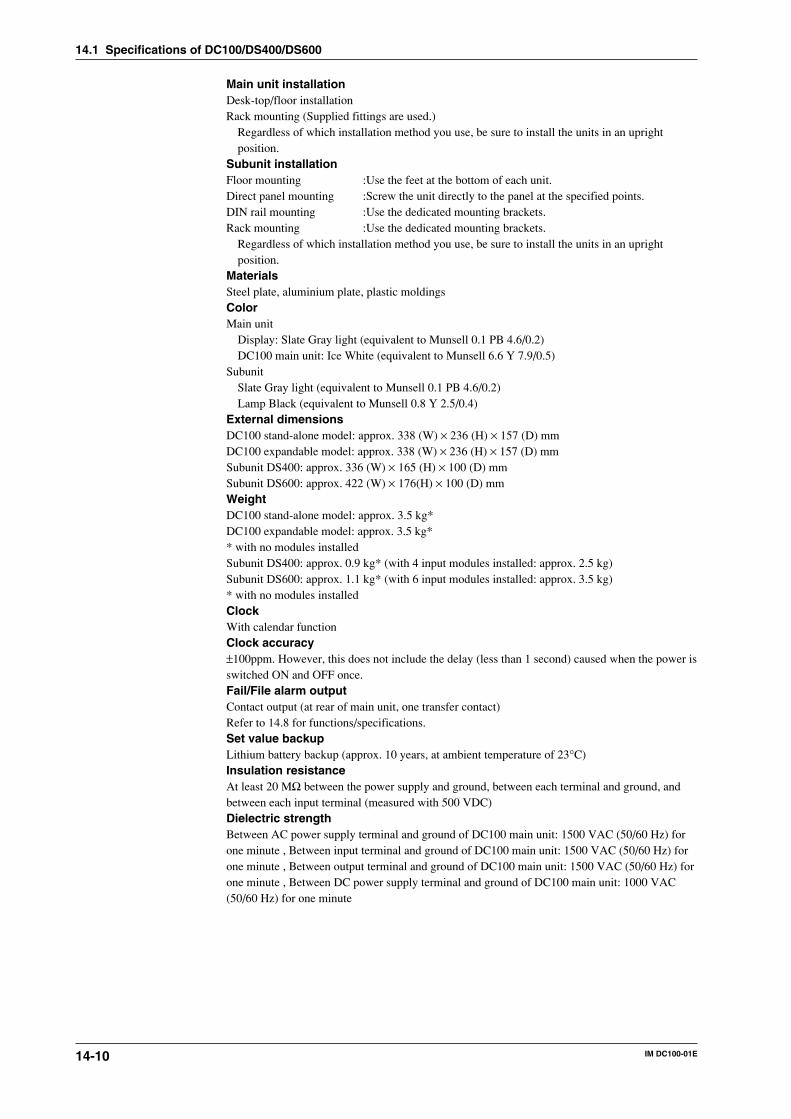
14-10 IM DC100-01E
Main unit installationDesk-top/floor installationRack mounting (Supplied fittings are used.)
Regardless of which installation method you use, be sure to install the units in an uprightposition.
Subunit installationFloor mounting :Use the feet at the bottom of each unit.Direct panel mounting :Screw the unit directly to the panel at the specified points.DIN rail mounting :Use the dedicated mounting brackets.Rack mounting :Use the dedicated mounting brackets.
Regardless of which installation method you use, be sure to install the units in an uprightposition.
MaterialsSteel plate, aluminium plate, plastic moldingsColorMain unit
Display: Slate Gray light (equivalent to Munsell 0.1 PB 4.6/0.2)DC100 main unit: Ice White (equivalent to Munsell 6.6 Y 7.9/0.5)
SubunitSlate Gray light (equivalent to Munsell 0.1 PB 4.6/0.2)Lamp Black (equivalent to Munsell 0.8 Y 2.5/0.4)
External dimensionsDC100 stand-alone model: approx. 338 (W) × 236 (H) × 157 (D) mmDC100 expandable model: approx. 338 (W) × 236 (H) × 157 (D) mmSubunit DS400: approx. 336 (W) × 165 (H) × 100 (D) mmSubunit DS600: approx. 422 (W) × 176(H) × 100 (D) mmWeightDC100 stand-alone model: approx. 3.5 kg*DC100 expandable model: approx. 3.5 kg** with no modules installedSubunit DS400: approx. 0.9 kg* (with 4 input modules installed: approx. 2.5 kg)Subunit DS600: approx. 1.1 kg* (with 6 input modules installed: approx. 3.5 kg)* with no modules installedClockWith calendar functionClock accuracy±100ppm. However, this does not include the delay (less than 1 second) caused when the power isswitched ON and OFF once.Fail/File alarm outputContact output (at rear of main unit, one transfer contact)Refer to 14.8 for functions/specifications.Set value backupLithium battery backup (approx. 10 years, at ambient temperature of 23°C)Insulation resistanceAt least 20 MΩ between the power supply and ground, between each terminal and ground, andbetween each input terminal (measured with 500 VDC)Dielectric strengthBetween AC power supply terminal and ground of DC100 main unit: 1500 VAC (50/60 Hz) forone minute , Between input terminal and ground of DC100 main unit: 1500 VAC (50/60 Hz) forone minute , Between output terminal and ground of DC100 main unit: 1500 VAC (50/60 Hz) forone minute , Between DC power supply terminal and ground of DC100 main unit: 1000 VAC(50/60 Hz) for one minute
14.1 Specifications of DC100/DS400/DS600
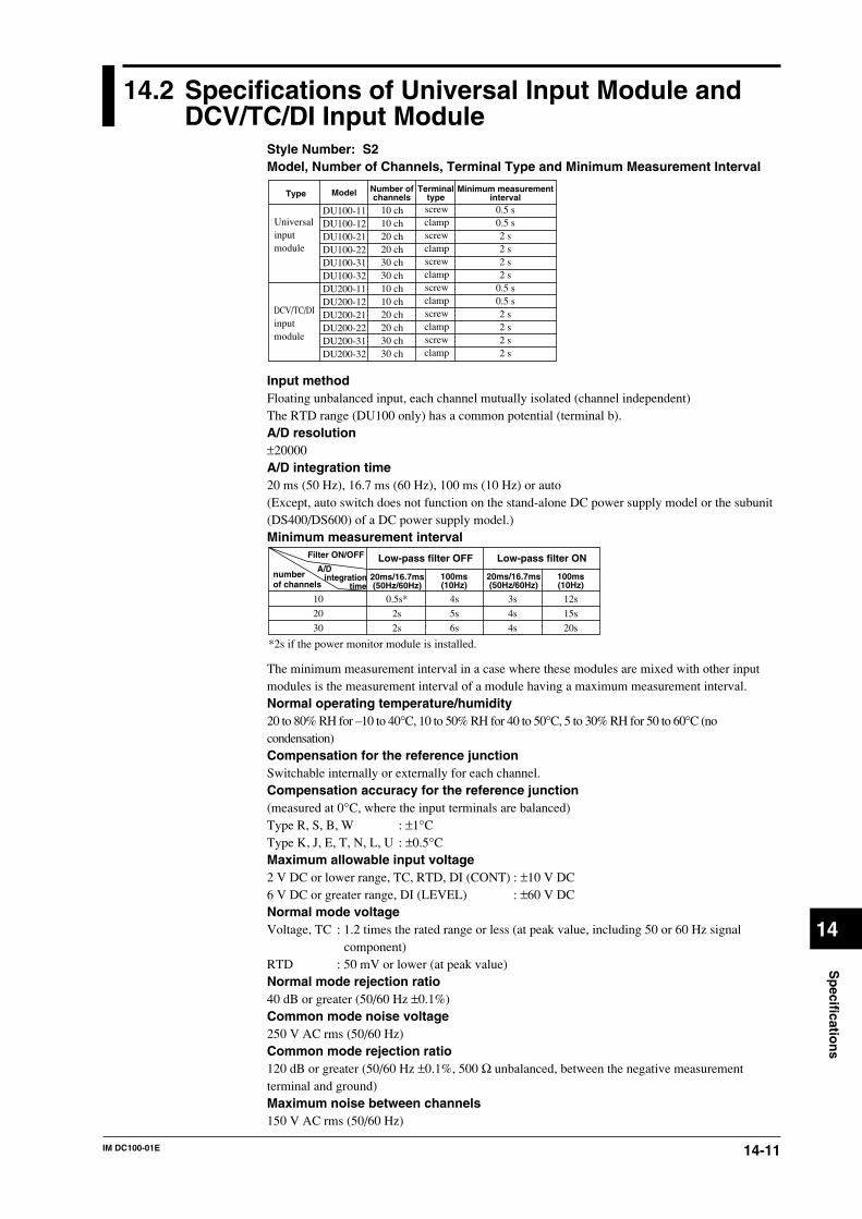
14-11IM DC100-01E
Sp
ecification
s
14
14.2 Specifications of Universal Input Module andDCV/TC/DI Input Module
Style Number: S2Model, Number of Channels, Terminal Type and Minimum Measurement Interval
0.5 s0.5 s2 s2 s2 s2 s
0.5 s0.5 s2 s2 s2 s2 s
screwclampscrewclampscrewclampscrewclampscrewclampscrewclamp
10 ch10 ch20 ch20 ch30 ch30 ch10 ch10 ch20 ch20 ch30 ch30 ch
DU100-11DU100-12DU100-21DU100-22DU100-31DU100-32DU200-11DU200-12DU200-21DU200-22DU200-31DU200-32
Type
Universalinputmodule
DCV/TC/DIinputmodule
Model Number ofchannels
Terminaltype
Minimum measurementinterval
Input methodFloating unbalanced input, each channel mutually isolated (channel independent)The RTD range (DU100 only) has a common potential (terminal b).A/D resolution±20000A/D integration time20 ms (50 Hz), 16.7 ms (60 Hz), 100 ms (10 Hz) or auto(Except, auto switch does not function on the stand-alone DC power supply model or the subunit(DS400/DS600) of a DC power supply model.)Minimum measurement interval
numberof channels
20ms/16.7ms(50Hz/60Hz)
4s
5s
6s
3s
4s
4s
12s
15s
20s
10
20
30
Low-pass filter OFF Low-pass filter ONFilter ON/OFF
A/D integration time
0.5s*
2s
2s
100ms(10Hz)
20ms/16.7ms(50Hz/60Hz)
100ms(10Hz)
*2s if the power monitor module is installed.
The minimum measurement interval in a case where these modules are mixed with other inputmodules is the measurement interval of a module having a maximum measurement interval.Normal operating temperature/humidity20 to 80% RH for –10 to 40°C, 10 to 50% RH for 40 to 50°C, 5 to 30% RH for 50 to 60°C (nocondensation)Compensation for the reference junctionSwitchable internally or externally for each channel.Compensation accuracy for the reference junction(measured at 0°C, where the input terminals are balanced)Type R, S, B, W : ±1°CType K, J, E, T, N, L, U : ±0.5°CMaximum allowable input voltage2 V DC or lower range, TC, RTD, DI (CONT) : ±10 V DC6 V DC or greater range, DI (LEVEL) : ±60 V DCNormal mode voltageVoltage, TC : 1.2 times the rated range or less (at peak value, including 50 or 60 Hz signal
component)RTD : 50 mV or lower (at peak value)Normal mode rejection ratio40 dB or greater (50/60 Hz ±0.1%)Common mode noise voltage250 V AC rms (50/60 Hz)Common mode rejection ratio120 dB or greater (50/60 Hz ±0.1%, 500 Ω unbalanced, between the negative measurementterminal and ground)Maximum noise between channels150 V AC rms (50/60 Hz)

14-12 IM DC100-01E
Measurement range, accuracy and resolutionAs described below, under the following operating conditions:Ambient temperature: 23 ±2°C; ambient humidity: 55 ±10% RH; power supply voltage: 90 to 250V AC (AC power supply)/10 to 32 V DC (DC power supply); power supply frequency: 50/60Hzwithin ±1% (AC power supply); warm-up time 30 minutes or more; vibrations and others notaffecting instrument operation. However, RTD input is not possible for the DCV/TC/DI inputmodule.
InputMeasurement (digital display)
DC Voltage
TC(Note that Accuracyof reference junctioncompensation is notconsidered).
RTD
High resolution RTD
Contact
20 mV60 mV200 mV2 V6 V20 V50 VR
SBK
EJTLUNWKPvsAu7FePt100(1mA)Pt100(2mA)JPt100(1mA)JPt100(2mA)Pt50(2mA)Ni100(1mA)SAMANi100(1mA)DINNi120(1mA)J263*BCu10 GECu10 L&NCu10 WEEDCu10 BAILEYPt100(1mA)Pt100(2mA)JPt100(1mA)JPt100(2mA)Voltage input
Contact input
–20.000 to 20.000 mV–60.00 to 60.00 mV–200.00 to 200.00 mV–2.0000 to 2.0000 V–6.000 to 6.000 V–20.000 to 20.000 V–50.00 to 50.00 V0.0 to 1760.0°C
0.0 to 1760.0°C0.0 to 1820.0°C–200.0 to 1370.0°C
–200.0 to 800.0°C–200.0 to 1100.0°C–200.0 to 400.0°C–200.0 to 900.0°C–200.0 to 400.0°C0.0 to 1300.0°C0.0 to 2315.0°C0.0 to 300.0K–200.0 to 600.0°C–200.0 to 250.0°C–200.0 to 550.0°C–200.0 to 250.0°C–200.0 to 550.0°C–200.0 to 250.0°C
–60.0 to 180.0°C–70.0 to 200.0°C0.0 to 300.0K–200.0 to 300.0°C
–140.00 to 150.00°C–70.00 to 70.00°C–140.00 to 150.00°C–70.00 to 70.00°COff for a voltage of less than 2.4 V.On for a voltage of 2.4 Vor more.(TTL)On/Off of contact
Type Measurement accuracyMaximumresolution
±(0.05% of rdg. + 5 digits)±(0.05% of rdg. + 2 digits)±(0.05% of rdg. + 2 digits)±(0.05% of rdg. + 2 digits)±(0.05% of rdg. + 2 digits)±(0.05% of rdg. + 2 digits)±(0.05% of rdg. + 2 digits)±(0.05% of rdg. + 1°C)However,R,S:0 to 100°C,±3.7°C100 to 300°C,±1.5°CB:400 to 600°C,±2°C, accuracyless than 400°C is not specified.±(0.05% of rdg. +0.7°C)However,K attains an accuracy of±(0.05% of rdg. +1°C) within the range between –200 to –100°C.±(0.05% of rdg. +0.5°C)However,J and L attain an accuracy of±(0.05% of rdg. +0.7°C) within the range between –200 to –100°C.
±(0.05% of rdg. +0.7°C) ±(0.05% of rdg. +1°C) ±(0.05% of rdg. +0.7K) ±(0.05% of rdg. +0.3°C)
±(0.05% of rdg. +0.3°C) ±(0.05% of rdg. +0.3°C)
±(0.05% of rdg. +0.3°C)
±(0.05% of rdg. +0.3K) ±(0.2% of rdg. +0.7°C)
±(0.05% of rdg. +0.3°C) ±(0.05% of rdg. +0.3°C) ±(0.05% of rdg. +0.3°C) ±(0.05% of rdg. +0.3°C)
Measurement range1 µV10 µV10 µV100 µV1 mV1 mV1 0mV
0.1°C
0.1K
0.1°C
0.1K
0.1°C
0.01°C
*1
*1
*1
*1
*1
*1
*1
*2
*2
*3
*4
*5
*5
*5
*5
*5
*6
*6
*7
*8
*8
*8
*8
*5
*5
*5
*5
*1 : R,S,B,K,E,J,T:ANSI,IEC 584,DIN IEC 584,JIS C 1602-1981*2 : L:Fe-CuNi,DIN43710,U:Cu-CuNi,DIN 43710*3 : N:Nicrosil-Nisil,IEC 584,DIN IEC 584*4 : W:W·5%RE-W·26%Re (Hoskins Mfg Co)*5 : Pt50:JIS C 1604-1981,JIS C 1606-1986 Pt100:JIS C 1604-1989,JIS C 1606-1989,IEC 751,DIN IEC 751 JPt100:JIS C 1604-1981,JIS C 1606-1989
*6 : SAMA/DIN*7 : McGRAW EDISON COMPANY*8 : ranges to which accuracy applies: Cu10 GE:–84.4 to 170.0°C, Cu10 L&N:–75.0 to 150.0°C, Cu10 WEED:–200.0 to 250.0°C, Cu10 BAILEY:–200.0 to 250.0°C
Noise rejectionRejection by integration type A/D, lowpass filter, or moving averaging.Input resistanceMin. 10 MΩ at 2 V DC or lower, thermocouple rangeApprox. 1 MΩ at 6 V DC or higher.Insulation resistanceMin. 20 MΩ at 500 V DC between the input terminal and ground.
14.2 Specifications of Universal Input Module and DCV/TC/DI Input Module
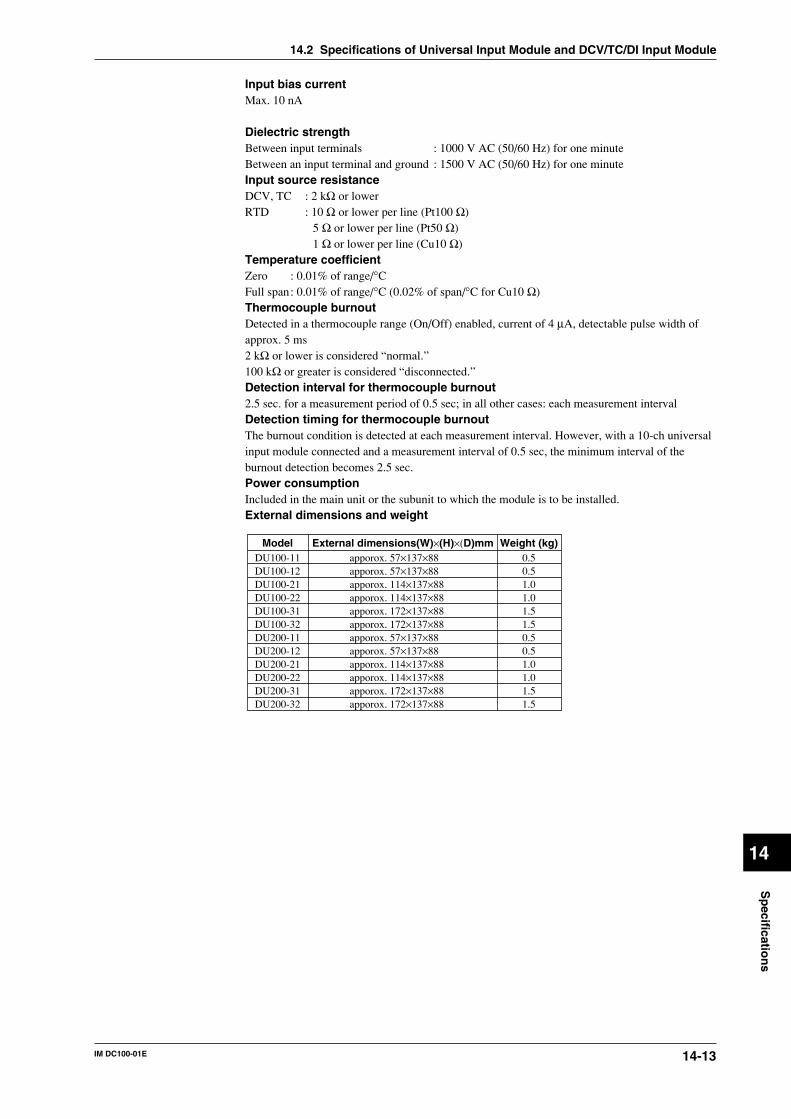
14-13IM DC100-01E
Sp
ecification
s
14
Input bias currentMax. 10 nA
Dielectric strengthBetween input terminals : 1000 V AC (50/60 Hz) for one minuteBetween an input terminal and ground : 1500 V AC (50/60 Hz) for one minuteInput source resistanceDCV, TC : 2 kΩ or lowerRTD : 10 Ω or lower per line (Pt100 Ω)
5 Ω or lower per line (Pt50 Ω)1 Ω or lower per line (Cu10 Ω)
Temperature coefficientZero : 0.01% of range/°CFull span: 0.01% of range/°C (0.02% of span/°C for Cu10 Ω)Thermocouple burnoutDetected in a thermocouple range (On/Off) enabled, current of 4 µA, detectable pulse width ofapprox. 5 ms2 kΩ or lower is considered “normal.”100 kΩ or greater is considered “disconnected.”Detection interval for thermocouple burnout2.5 sec. for a measurement period of 0.5 sec; in all other cases: each measurement intervalDetection timing for thermocouple burnoutThe burnout condition is detected at each measurement interval. However, with a 10-ch universalinput module connected and a measurement interval of 0.5 sec, the minimum interval of theburnout detection becomes 2.5 sec.Power consumptionIncluded in the main unit or the subunit to which the module is to be installed.External dimensions and weight
Weight (kg)0.50.51.01.01.51.50.50.51.01.01.51.5
External dimensions(W)×(H)×(D)mmapporox. 57×137×88apporox. 57×137×88apporox. 114×137×88apporox. 114×137×88apporox. 172×137×88apporox. 172×137×88apporox. 57×137×88apporox. 57×137×88apporox. 114×137×88apporox. 114×137×88apporox. 172×137×88apporox. 172×137×88
ModelDU100-11DU100-12DU100-21DU100-22DU100-31DU100-32DU200-11DU200-12DU200-21DU200-22DU200-31DU200-32
14.2 Specifications of Universal Input Module and DCV/TC/DI Input Module
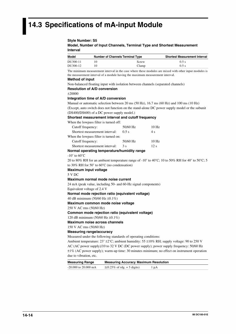
14-14 IM DC100-01E
14.3 Specifications of mA-input Module
Style Number: S5Model, Number of Input Channels, Terminal Type and Shortest MeasurementInterval
Model Number of Channels Terminal Type Shortest Measurement Interval
DU300-11 10 Screw 0.5 sDU300-12 10 Clamp 0.5 s
The minimum measurement interval in the case where these modules are mixed with other input modules isthe measurement interval of a module having the maximum measurement interval.
Method of inputNon-balanced floating input with isolation between channels (separated channels)Resolution of A/D conversion±20000Integration time of A/D conversionManual or automatic selection between 20 ms (50 Hz), 16.7 ms (60 Hz) and 100 ms (10 Hz)(Except, auto switch does not function on the stand-alone DC power supply model or the subunit(DS400/DS600) of a DC power supply model.)Shortest measurement interval and cutoff frequencyWhen the lowpass filter is turned off:
Cutoff frequency: 50/60 Hz 10 HzShortest measurement interval: 0.5 s 4 s
When the lowpass filter is turned on:Cutoff frequency: 50/60 Hz 10 HzShortest measurement interval: 3 s 12 s
Normal operating temperature/humidity range-10˚ to 60˚C20 to 80% RH for an ambient temperature range of -10˚ to 40˚C; 10 to 50% RH for 40˚ to 50˚C; 5to 30% RH for 50˚ to 60˚C (no condensation)Maximum input voltage5 V DCMaximum normal mode noise current24 mA (peak value, including 50- and 60-Hz signal components)Equivalent voltage of 2.4 VNormal mode rejection ratio (equivalent voltage)40 dB minimum (50/60 Hz ±0.1%)Maximum common mode noise voltage250 V AC rms (50/60 Hz)Common mode rejection ratio (equivalent voltage)120 dB minimum (50/60 Hz ±0.1%)Maximum noise across channels150 V AC rms (50/60 Hz)Measuring range/accuracyMeasured under the following standards of operating conditions:Ambient temperature: 23˚ ±2˚C; ambient humidity: 55 ±10% RH; supply voltage: 90 to 250 VAC (AC power supply)/10 to 32 V DC (DC power supply); power supply frequency: 50/60 Hz±1% (AC power supply); warm-up time: 30 minutes minimum; no effect on instrument operationdue to vibration, etc.
Measuring Range Measuring Accuracy Maximum Resolution
-20.000 to 20.000 mA ±(0.25% of rdg. + 5 digits) 1 µA
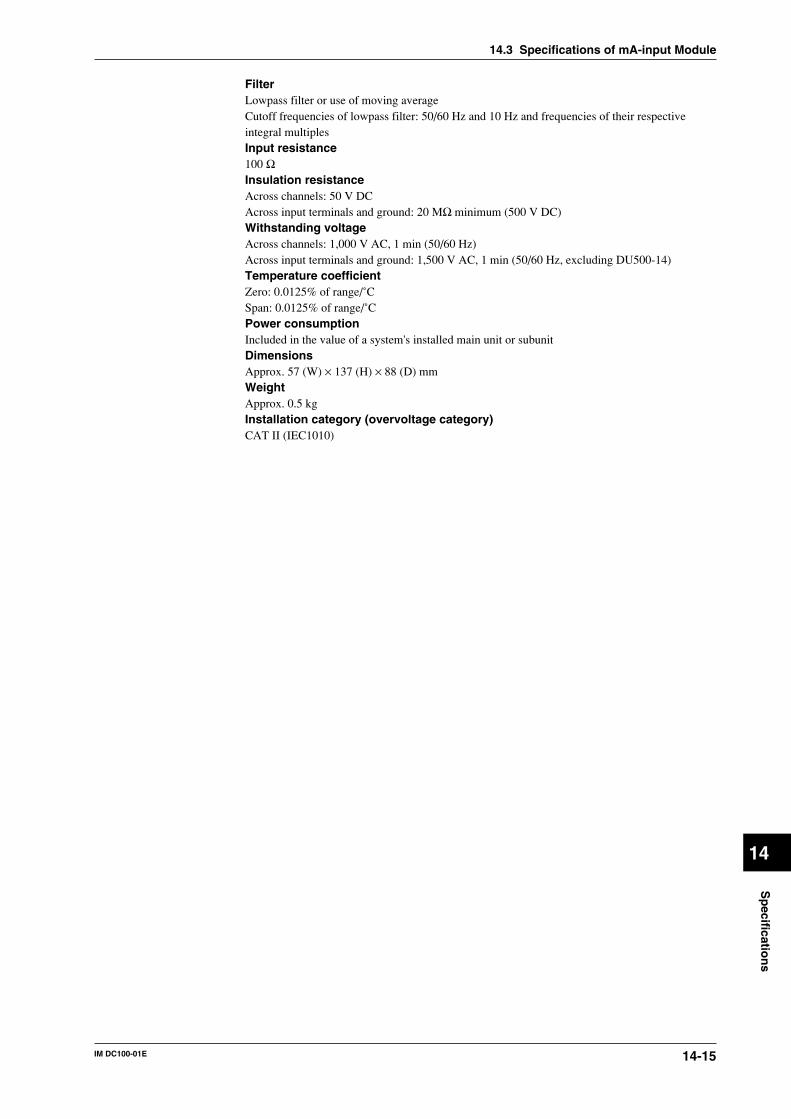
14-15IM DC100-01E
Sp
ecification
s
14
FilterLowpass filter or use of moving averageCutoff frequencies of lowpass filter: 50/60 Hz and 10 Hz and frequencies of their respectiveintegral multiplesInput resistance100 ΩInsulation resistanceAcross channels: 50 V DCAcross input terminals and ground: 20 MΩ minimum (500 V DC)Withstanding voltageAcross channels: 1,000 V AC, 1 min (50/60 Hz)Across input terminals and ground: 1,500 V AC, 1 min (50/60 Hz, excluding DU500-14)Temperature coefficientZero: 0.0125% of range/˚CSpan: 0.0125% of range/˚CPower consumptionIncluded in the value of a system's installed main unit or subunitDimensionsApprox. 57 (W) × 137 (H) × 88 (D) mmWeightApprox. 0.5 kgInstallation category (overvoltage category)CAT II (IEC1010)
14.3 Specifications of mA-input Module
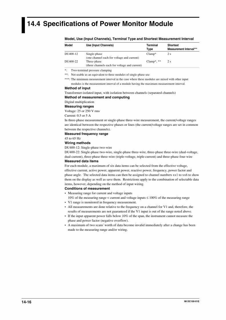
14-16 IM DC100-01E
14.4 Specifications of Power Monitor Module
Model, Use (Input Channels), Terminal Type and Shortest Measurement Interval
Model Use (Input Channels) Terminal ShortestType Measurement Interval***
DU400-12 Single-phase Clamp* 2 s(one channel each for voltage and current)
DU400-22 Three-phase Clamp*, ** 2 s(three channels each for voltage and current)
*: Two-terminal pressure clamping
**: Not usable as an equivalent to three modules of single-phase use
***: The minimum measurement interval in the case where these modules are mixed with other input
modules is the measurement interval of a module having the maximum measurement interval.
Method of inputTransformer-isolated input, with isolation between channels (separated channels)Method of measurement and computingDigital multiplicationMeasuring rangesVoltage: 25 or 250 V rmsCurrent: 0.5 or 5 AIn three-phase measurement or single-phase three-wire measurement, the current/voltage rangesare identical between the respective phases or lines (the current/voltage ranges are set in commonbetween the respective channels).Measured frequency range45 to 65 HzWiring methodsDU400-12: Single-phase two-wireDU400-22: Single-phase two-wire, single-phase three-wire, three-phase three-wire (dual-voltage,dual-current), three-phase three-wire (triple-voltage, triple-current) and three-phase four-wireMeasured data itemsFor each module, a maximum of six data items can be selected from the effective voltage,effective current, active power, apparent power, reactive power, frequency, power factor andphase angle. The selected data items can then be assigned to channel numbers xx1 to xx6 to showthem on the display as well as save them. Restrictions apply to the combination of selectable dataitems, however, depending on the method of input wiring.Conditions of measurement• Measuring range for current and voltage inputs
10% of the measuring range < current and voltage inputs ≤ 100% of the measuring range• V1 range is monitored in frequency measurement.• All measurements are done relative to the frequency on a channel for V1 and, therefore, the
results of measurements are not guaranteed if the V1 input is out of the range noted above.• If the input apparent power falls below 10% of the span, the instrument cannot measure the
phase and power factor (negative overflow).• A maximum of two scans' worth of data become invalid immediately after a change has been
made to the measuring range and/or wiring.
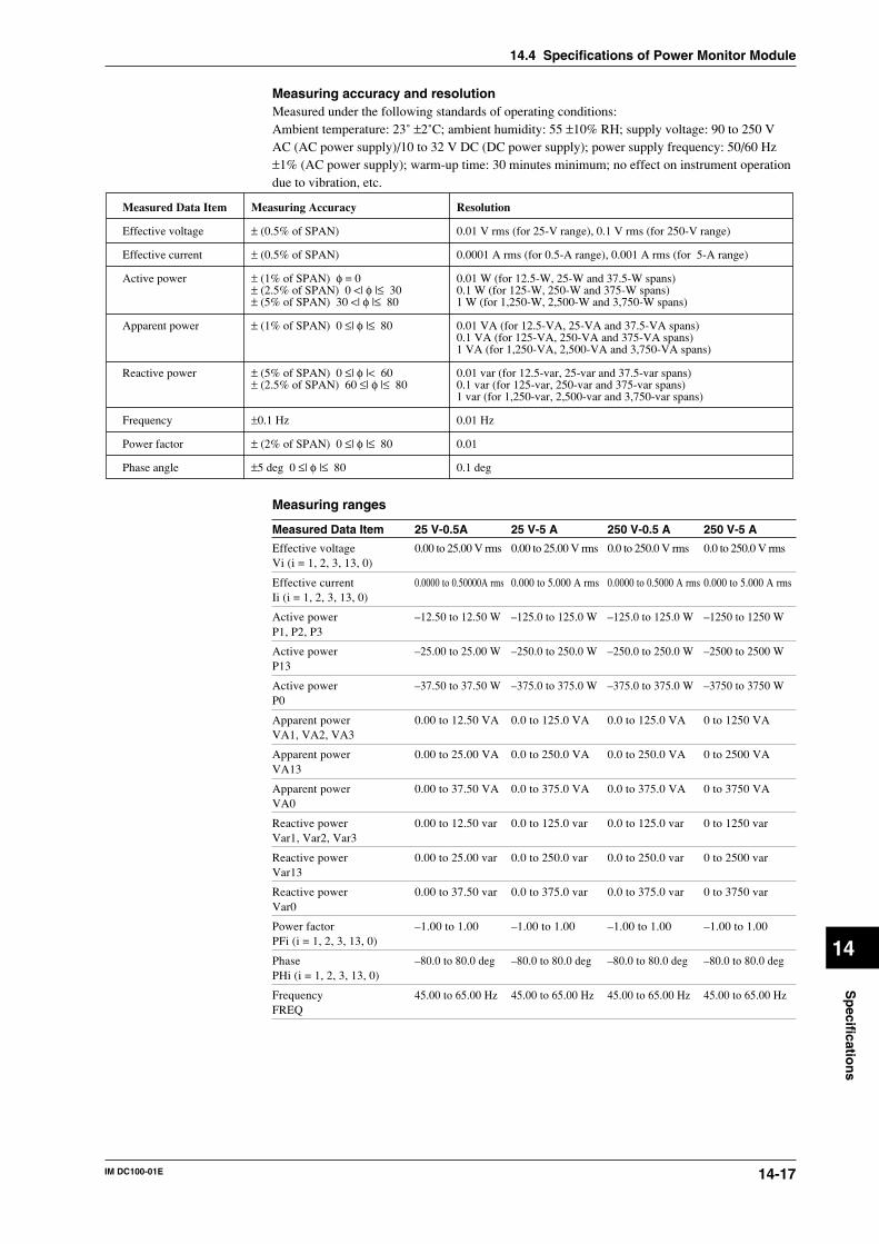
14-17IM DC100-01E
Sp
ecification
s
14
Measuring accuracy and resolutionMeasured under the following standards of operating conditions:Ambient temperature: 23˚ ±2˚C; ambient humidity: 55 ±10% RH; supply voltage: 90 to 250 VAC (AC power supply)/10 to 32 V DC (DC power supply); power supply frequency: 50/60 Hz±1% (AC power supply); warm-up time: 30 minutes minimum; no effect on instrument operationdue to vibration, etc.
Measured Data Item Measuring Accuracy Resolution
Effective voltage ± (0.5% of SPAN) 0.01 V rms (for 25-V range), 0.1 V rms (for 250-V range)
Effective current ± (0.5% of SPAN) 0.0001 A rms (for 0.5-A range), 0.001 A rms (for 5-A range)
Active power ± (1% of SPAN) φ = 0 0.01 W (for 12.5-W, 25-W and 37.5-W spans)± (2.5% of SPAN) 0 <| φ |≤ 30 0.1 W (for 125-W, 250-W and 375-W spans)± (5% of SPAN) 30 <| φ |≤ 80 1 W (for 1,250-W, 2,500-W and 3,750-W spans)
Apparent power ± (1% of SPAN) 0 ≤| φ |≤ 80 0.01 VA (for 12.5-VA, 25-VA and 37.5-VA spans)0.1 VA (for 125-VA, 250-VA and 375-VA spans)1 VA (for 1,250-VA, 2,500-VA and 3,750-VA spans)
Reactive power ± (5% of SPAN) 0 ≤| φ |< 60 0.01 var (for 12.5-var, 25-var and 37.5-var spans)± (2.5% of SPAN) 60 ≤| φ |≤ 80 0.1 var (for 125-var, 250-var and 375-var spans)
1 var (for 1,250-var, 2,500-var and 3,750-var spans)
Frequency ±0.1 Hz 0.01 Hz
Power factor ± (2% of SPAN) 0 ≤| φ |≤ 80 0.01
Phase angle ±5 deg 0 ≤| φ |≤ 80 0.1 deg
Measuring ranges
Measured Data Item 25 V-0.5A 25 V-5 A 250 V-0.5 A 250 V-5 A
Effective voltage 0.00 to 25.00 V rms 0.00 to 25.00 V rms 0.0 to 250.0 V rms 0.0 to 250.0 V rmsVi (i = 1, 2, 3, 13, 0)
Effective current 0.0000 to 0.50000A rms 0.000 to 5.000 A rms 0.0000 to 0.5000 A rms 0.000 to 5.000 A rmsIi (i = 1, 2, 3, 13, 0)
Active power –12.50 to 12.50 W –125.0 to 125.0 W –125.0 to 125.0 W –1250 to 1250 WP1, P2, P3
Active power –25.00 to 25.00 W –250.0 to 250.0 W –250.0 to 250.0 W –2500 to 2500 WP13
Active power –37.50 to 37.50 W –375.0 to 375.0 W –375.0 to 375.0 W –3750 to 3750 WP0
Apparent power 0.00 to 12.50 VA 0.0 to 125.0 VA 0.0 to 125.0 VA 0 to 1250 VAVA1, VA2, VA3
Apparent power 0.00 to 25.00 VA 0.0 to 250.0 VA 0.0 to 250.0 VA 0 to 2500 VAVA13
Apparent power 0.00 to 37.50 VA 0.0 to 375.0 VA 0.0 to 375.0 VA 0 to 3750 VAVA0
Reactive power 0.00 to 12.50 var 0.0 to 125.0 var 0.0 to 125.0 var 0 to 1250 varVar1, Var2, Var3
Reactive power 0.00 to 25.00 var 0.0 to 250.0 var 0.0 to 250.0 var 0 to 2500 varVar13
Reactive power 0.00 to 37.50 var 0.0 to 375.0 var 0.0 to 375.0 var 0 to 3750 varVar0
Power factor –1.00 to 1.00 –1.00 to 1.00 –1.00 to 1.00 –1.00 to 1.00PFi (i = 1, 2, 3, 13, 0)
Phase –80.0 to 80.0 deg –80.0 to 80.0 deg –80.0 to 80.0 deg –80.0 to 80.0 degPHi (i = 1, 2, 3, 13, 0)
Frequency 45.00 to 65.00 Hz 45.00 to 65.00 Hz 45.00 to 65.00 Hz 45.00 to 65.00 HzFREQ
14.4 Specifications of Power Monitor Module
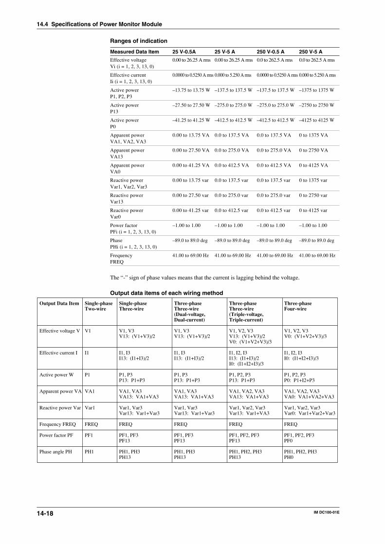
14-18 IM DC100-01E
Ranges of indication
Measured Data Item 25 V-0.5A 25 V-5 A 250 V-0.5 A 250 V-5 A
Effective voltage 0.00 to 26.25 A rms 0.00 to 26.25 A rms 0.0 to 262.5 A rms 0.0 to 262.5 A rmsVi (i = 1, 2, 3, 13, 0)
Effective current 0.0000 to 0.5250 A rms 0.000 to 5.250 A rms 0.0000 to 0.5250 A rms 0.000 to 5.250 A rmsIi (i = 1, 2, 3, 13, 0)
Active power –13.75 to 13.75 W –137.5 to 137.5 W –137.5 to 137.5 W –1375 to 1375 WP1, P2, P3
Active power –27.50 to 27.50 W –275.0 to 275.0 W –275.0 to 275.0 W –2750 to 2750 WP13
Active power –41.25 to 41.25 W –412.5 to 412.5 W –412.5 to 412.5 W –4125 to 4125 WP0
Apparent power 0.00 to 13.75 VA 0.0 to 137.5 VA 0.0 to 137.5 VA 0 to 1375 VAVA1, VA2, VA3
Apparent power 0.00 to 27.50 VA 0.0 to 275.0 VA 0.0 to 275.0 VA 0 to 2750 VAVA13
Apparent power 0.00 to 41.25 VA 0.0 to 412.5 VA 0.0 to 412.5 VA 0 to 4125 VAVA0
Reactive power 0.00 to 13.75 var 0.0 to 137.5 var 0.0 to 137.5 var 0 to 1375 varVar1, Var2, Var3
Reactive power 0.00 to 27.50 var 0.0 to 275.0 var 0.0 to 275.0 var 0 to 2750 varVar13
Reactive power 0.00 to 41.25 var 0.0 to 412.5 var 0.0 to 412.5 var 0 to 4125 varVar0
Power factor –1.00 to 1.00 –1.00 to 1.00 –1.00 to 1.00 –1.00 to 1.00PFi (i = 1, 2, 3, 13, 0)
Phase –89.0 to 89.0 deg –89.0 to 89.0 deg –89.0 to 89.0 deg –89.0 to 89.0 degPHi (i = 1, 2, 3, 13, 0)
Frequency 41.00 to 69.00 Hz 41.00 to 69.00 Hz 41.00 to 69.00 Hz 41.00 to 69.00 HzFREQ
The “-” sign of phase values means that the current is lagging behind the voltage.
Output data items of each wiring method
Output Data Item Single-phase Single-phase Three-phase Three-phase Three-phaseTwo-wire Three-wire Three-wire Three-wire Four-wire
(Dual-voltage, (Triple-voltage,Dual-current) Triple-current)
Effective voltage V V1 V1, V3 V1, V3 V1, V2, V3 V1, V2, V3V13: (V1+V3)/2 V13: (V1+V3)/2 V13: (V1+V3)/2 V0: (V1+V2+V3)/3
V0: (V1+V2+V3)/3
Effective current I I1 I1, I3 I1, I3 I1, I2, I3 I1, I2, I3I13: (I1+I3)/2 I13: (I1+I3)/2 I13: (I1+I3)/2 I0: (I1+I2+I3)/3
I0: (I1+I2+I3)/3
Active power W P1 P1, P3 P1, P3 P1, P2, P3 P1, P2, P3P13: P1+P3 P13: P1+P3 P13: P1+P3 P0: P1+I2+P3
Apparent power VA VA1 VA1, VA3 VA1, VA3 VA1, VA2, VA3 VA1, VA2, VA3VA13: VA1+VA3 VA13: VA1+VA3 VA13: VA1+VA3 VA0: VA1+VA2+VA3
Reactive power Var Var1 Var1, Var3 Var1, Var3 Var1, Var2, Var3 Var1, Var2, Var3Var13: Var1+Var3 Var13: Var1+Var3 Var13: Var1+VA3 Var0: Var1+Var2+Var3
Frequency FREQ FREQ FREQ FREQ FREQ FREQ
Power factor PF PF1 PF1, PF3 PF1, PF3 PF1, PF2, PF3 PF1, PF2, PF3PF13 PF13 PF13 PF0
Phase angle PH PH1 PH1, PH3 PH1, PH3 PH1, PH2, PH3 PH1, PH2, PH3PH13 PH13 PH13 PH0
14.4 Specifications of Power Monitor Module
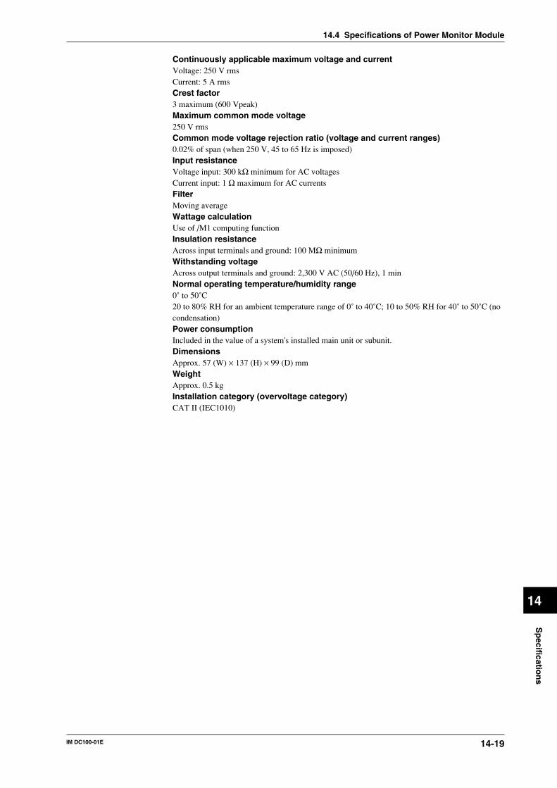
14-19IM DC100-01E
Sp
ecification
s
14
Continuously applicable maximum voltage and currentVoltage: 250 V rmsCurrent: 5 A rmsCrest factor3 maximum (600 Vpeak)Maximum common mode voltage250 V rmsCommon mode voltage rejection ratio (voltage and current ranges)0.02% of span (when 250 V, 45 to 65 Hz is imposed)Input resistanceVoltage input: 300 kΩ minimum for AC voltagesCurrent input: 1 Ω maximum for AC currentsFilterMoving averageWattage calculationUse of /M1 computing functionInsulation resistanceAcross input terminals and ground: 100 MΩ minimumWithstanding voltageAcross output terminals and ground: 2,300 V AC (50/60 Hz), 1 minNormal operating temperature/humidity range0˚ to 50˚C20 to 80% RH for an ambient temperature range of 0˚ to 40˚C; 10 to 50% RH for 40˚ to 50˚C (nocondensation)Power consumptionIncluded in the value of a system's installed main unit or subunit.DimensionsApprox. 57 (W) × 137 (H) × 99 (D) mmWeightApprox. 0.5 kgInstallation category (overvoltage category)CAT II (IEC1010)
14.4 Specifications of Power Monitor Module
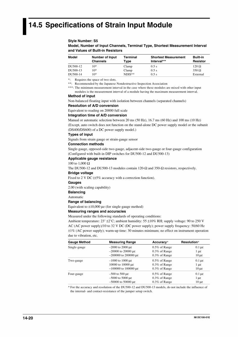
14-20 IM DC100-01E
14.5 Specifications of Strain Input Module
Style Number: S5Model, Number of Input Channels, Terminal Type, Shortest Measurement Intervaland Values of Built-in Resistors
Model Number of Input Terminal Shortest Measurement Built-inChannels Type Interval*** Resistor
DU500-12 10* Clamp 0.5 s 120 ΩDU500-13 10* Clamp 0.5 s 350 ΩDU500-14 10* NDIS** 0.5 s External
*: Requires the space of two slots.**: Recommended by the Japanese Nondestructive Inspection Association***: The minimum measurement interval in the case where these modules are mixed with other input
modules is the measurement interval of a module having the maximum measurement interval.
Method of inputNon-balanced floating input with isolation between channels (separated channels)Resolution of A/D conversionEquivalent to reading on 20000 full scaleIntegration time of A/D conversionManual or automatic selection between 20 ms (50 Hz), 16.7 ms (60 Hz) and 100 ms (10 Hz)(Except, auto switch does not function on the stand-alone DC power supply model or the subunit(DS400/DS600) of a DC power supply model.)Types of inputSignals from strain gauge or strain-gauge sensorConnection methodsSingle-gauge, opposed-side two-gauge, adjacent-side two-gauge or four-gauge configuration(Configured with built-in DIP switches for DU500-12 and DU500-13)Applicable gauge resistance100 to 1,000 ΩThe DU500-12 and DU500-13 modules contain 120-Ω and 350-Ω resistors, respectively.Bridge voltageFixed to 2 V DC (±5% accuracy with a correction function).Gauges2.00 (with scaling capability)BalancingAutomaticRange of balancingEquivalent to ±10,000 µe (for single-gauge method)Measuring ranges and accuraciesMeasured under the following standards of operating conditions:Ambient temperature: 23˚ ±2˚C; ambient humidity: 55 ±10% RH; supply voltage: 90 to 250 VAC (AC power supply)/10 to 32 V DC (DC power supply); power supply frequency: 50/60 Hz±1% (AC power supply); warm-up time: 30 minutes minimum; no effect on instrument operationdue to vibration, etc.
Gauge Method Measuring Range Accuracy* Resolution*
Single-gauge –2000 to 2000 µε 0.5% of Range 0.1 µε–20000 to 20000 µε 0.3% of Range 1 µε–200000 to 200000 µε 0.3% of Range 10 µε
Two-gauge –1000 to 1000 µε 0.5% of Range 0.1 µε10000 to 10000 µε 0.3% of Range 1 µε–100000 to 100000 µε 0.3% of Range 10 µε
Four-gauge –500 to 500 µε 0.5% of Range 0.1 µε–5000 to 5000 µε 0.3% of Range 1 µε–50000 to 50000 µε 0.3% of Range 10 µε
* For the accuracy and resolution of the DU500-12 and DU500-13 models, do not include the influence ofthe internal- and contact-resistance of the jumper setup switch.
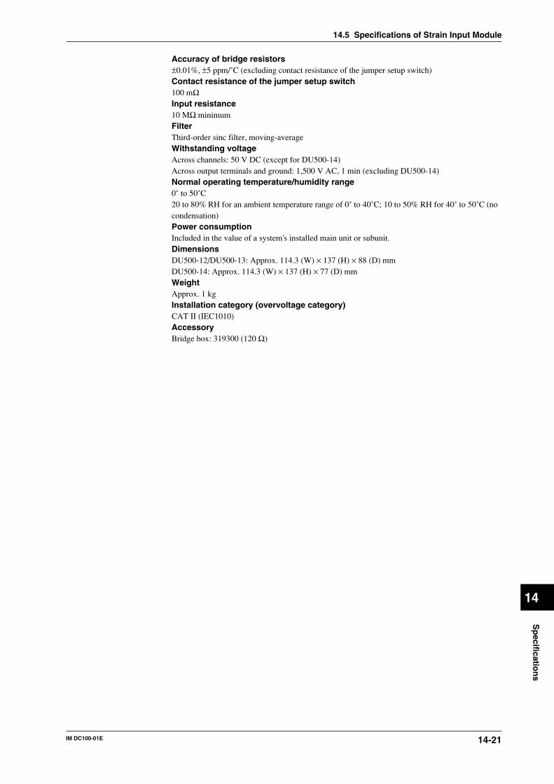
14-21IM DC100-01E
Sp
ecification
s
14
Accuracy of bridge resistors±0.01%, ±5 ppm/˚C (excluding contact resistance of the jumper setup switch)Contact resistance of the jumper setup switch100 mΩInput resistance10 MΩ minimumFilterThird-order sinc filter, moving-averageWithstanding voltageAcross channels: 50 V DC (except for DU500-14)Across output terminals and ground: 1,500 V AC, 1 min (excluding DU500-14)Normal operating temperature/humidity range0˚ to 50˚C20 to 80% RH for an ambient temperature range of 0˚ to 40˚C; 10 to 50% RH for 40˚ to 50˚C (nocondensation)Power consumptionIncluded in the value of a system's installed main unit or subunit.DimensionsDU500-12/DU500-13: Approx. 114.3 (W) × 137 (H) × 88 (D) mmDU500-14: Approx. 114.3 (W) × 137 (H) × 77 (D) mmWeightApprox. 1 kgInstallation category (overvoltage category)CAT II (IEC1010)AccessoryBridge box: 319300 (120 Ω)
14.5 Specifications of Strain Input Module
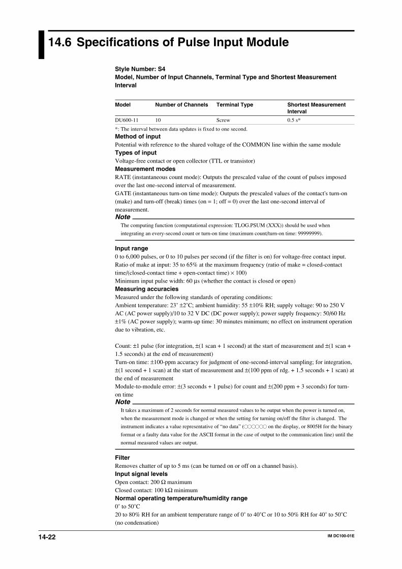
14-22 IM DC100-01E
14.6 Specifications of Pulse Input Module
Style Number: S4Model, Number of Input Channels, Terminal Type and Shortest MeasurementInterval
Model Number of Channels Terminal Type Shortest MeasurementInterval
DU600-11 10 Screw 0.5 s*
*: The interval between data updates is fixed to one second.
Method of inputPotential with reference to the shared voltage of the COMMON line within the same moduleTypes of inputVoltage-free contact or open collector (TTL or transistor)Measurement modesRATE (instantaneous count mode): Outputs the prescaled value of the count of pulses imposedover the last one-second interval of measurement.GATE (instantaneous turn-on time mode): Outputs the prescaled values of the contact's turn-on(make) and turn-off (break) times (on = 1; off = 0) over the last one-second interval ofmeasurement.Note
The computing function (computational expression: TLOG.PSUM (XXX)) should be used when
integrating an every-second count or turn-on time (maximum count/turn-on time: 99999999).
Input range0 to 6,000 pulses, or 0 to 10 pulses per second (if the filter is on) for voltage-free contact input.Ratio of make at input: 35 to 65% at the maximum frequency (ratio of make = closed-contacttime/(closed-contact time + open-contact time) × 100)Minimum input pulse width: 60 µs (whether the contact is closed or open)Measuring accuraciesMeasured under the following standards of operating conditions:Ambient temperature: 23˚ ±2˚C; ambient humidity: 55 ±10% RH; supply voltage: 90 to 250 VAC (AC power supply)/10 to 32 V DC (DC power supply); power supply frequency: 50/60 Hz±1% (AC power supply); warm-up time: 30 minutes minimum; no effect on instrument operationdue to vibration, etc.
Count: ±1 pulse (for integration, ±(1 scan + 1 second) at the start of measurement and ±(1 scan +1.5 seconds) at the end of measurement)Turn-on time: ±100-ppm accuracy for judgment of one-second-interval sampling; for integration,±(1 second + 1 scan) at the start of measurement and ±(100 ppm of rdg. + 1.5 seconds + 1 scan) atthe end of measurementModule-to-module error: ±(3 seconds + 1 pulse) for count and ±(200 ppm + 3 seconds) for turn-on timeNote
It takes a maximum of 2 seconds for normal measured values to be output when the power is turned on,
when the measurement mode is changed or when the setting for turning on/off the filter is changed. The
instrument indicates a value representative of “no data” ( on the display, or 8005H for the binary
format or a faulty data value for the ASCII format in the case of output to the communication line) until the
normal measured values are output.
FilterRemoves chatter of up to 5 ms (can be turned on or off on a channel basis).Input signal levelsOpen contact: 200 Ω maximumClosed contact: 100 kΩ minimumNormal operating temperature/humidity range0˚ to 50˚C20 to 80% RH for an ambient temperature range of 0˚ to 40˚C or 10 to 50% RH for 40˚ to 50˚C(no condensation)
14-23IM DC100-01E
Sp
ecification
s
14
Normal operating magnetic-field strength400 A/m maximumMaximum input voltage5 V DCSignal source rating15 V DC, 30 mA minimumInsulation resistanceAcross input terminals and ground: 20 MΩ minimum (500 V DC)Withstanding voltageAcross output terminals and ground: 500 V DC, 1 min (no channel-to-channel isolation)Power consumptionIncluded in the value of a system's installed main unit or subunit.DimensionsApprox. 57 (W) × 137 (H) × 68 (D) mmWeightApprox. 0.3 kgInstallation category (overvoltage category)CAT II (IEC1010)
14.6 Specifications of Pulse Input Module
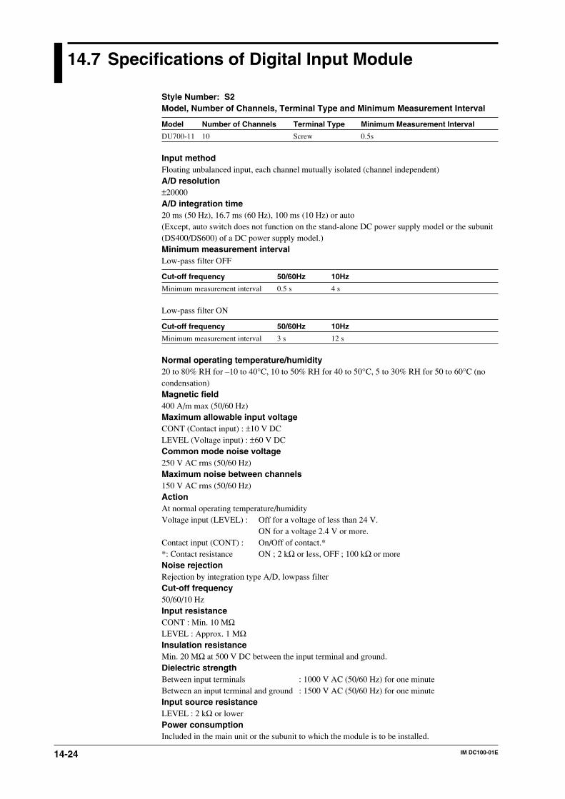
14-24 IM DC100-01E
14.7 Specifications of Digital Input Module
Style Number: S2Model, Number of Channels, Terminal Type and Minimum Measurement Interval
Model Number of Channels Terminal Type Minimum Measurement Interval
DU700-11 10 Screw 0.5s
Input methodFloating unbalanced input, each channel mutually isolated (channel independent)A/D resolution±20000A/D integration time20 ms (50 Hz), 16.7 ms (60 Hz), 100 ms (10 Hz) or auto(Except, auto switch does not function on the stand-alone DC power supply model or the subunit(DS400/DS600) of a DC power supply model.)Minimum measurement intervalLow-pass filter OFF
Cut-off frequency 50/60Hz 10Hz
Minimum measurement interval 0.5 s 4 s
Low-pass filter ON
Cut-off frequency 50/60Hz 10Hz
Minimum measurement interval 3 s 12 s
Normal operating temperature/humidity20 to 80% RH for –10 to 40°C, 10 to 50% RH for 40 to 50°C, 5 to 30% RH for 50 to 60°C (nocondensation)Magnetic field400 A/m max (50/60 Hz)Maximum allowable input voltageCONT (Contact input) : ±10 V DCLEVEL (Voltage input) : ±60 V DCCommon mode noise voltage250 V AC rms (50/60 Hz)Maximum noise between channels150 V AC rms (50/60 Hz)ActionAt normal operating temperature/humidityVoltage input (LEVEL) : Off for a voltage of less than 24 V.
ON for a voltage 2.4 V or more.Contact input (CONT) : On/Off of contact.**: Contact resistance ON ; 2 kΩ or less, OFF ; 100 kΩ or moreNoise rejectionRejection by integration type A/D, lowpass filterCut-off frequency50/60/10 HzInput resistanceCONT : Min. 10 MΩLEVEL : Approx. 1 MΩInsulation resistanceMin. 20 MΩ at 500 V DC between the input terminal and ground.Dielectric strengthBetween input terminals : 1000 V AC (50/60 Hz) for one minuteBetween an input terminal and ground : 1500 V AC (50/60 Hz) for one minuteInput source resistanceLEVEL : 2 kΩ or lowerPower consumptionIncluded in the main unit or the subunit to which the module is to be installed.

14-25IM DC100-01E
Sp
ecification
s
14
DimensionsApproximately 57(W) x 137(H) x 68(D) (mm)Weight0.5 kgInstallation Category (Overvoltage Category)CAT II (IEC 1010)
14.7 Specifications of Digital Input Module
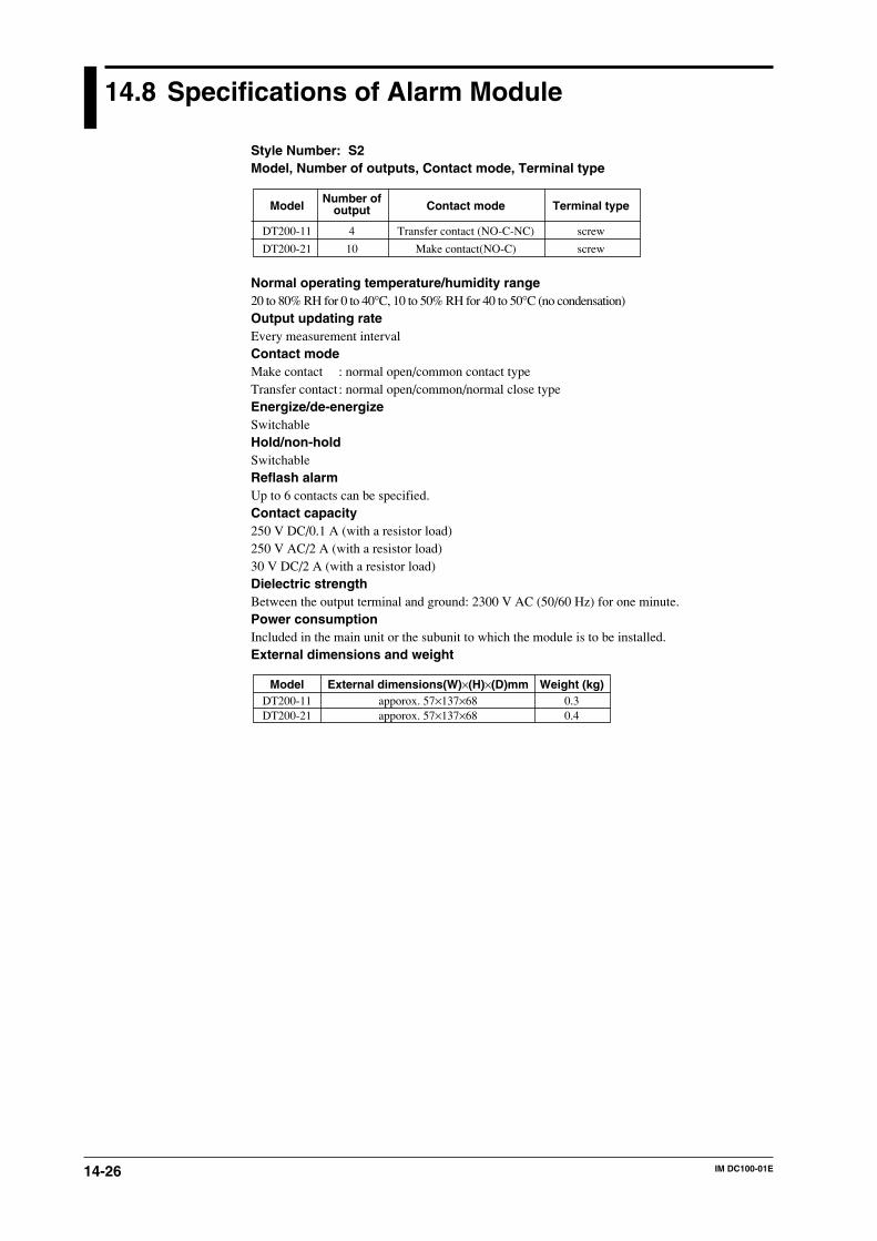
14-26 IM DC100-01E
14.8 Specifications of Alarm Module
Style Number: S2Model, Number of outputs, Contact mode, Terminal type
Contact mode
Transfer contact (NO-C-NC)
Make contact(NO-C)
Terminal type
screw
screw
Number ofoutput
4
10
Model
DT200-11
DT200-21
Normal operating temperature/humidity range20 to 80% RH for 0 to 40°C, 10 to 50% RH for 40 to 50°C (no condensation)Output updating rateEvery measurement intervalContact modeMake contact : normal open/common contact typeTransfer contact: normal open/common/normal close typeEnergize/de-energizeSwitchableHold/non-holdSwitchableReflash alarmUp to 6 contacts can be specified.Contact capacity250 V DC/0.1 A (with a resistor load)250 V AC/2 A (with a resistor load)30 V DC/2 A (with a resistor load)Dielectric strengthBetween the output terminal and ground: 2300 V AC (50/60 Hz) for one minute.Power consumptionIncluded in the main unit or the subunit to which the module is to be installed.External dimensions and weight
Weight (kg)0.30.4
External dimensions(W)×(H)×(D)mmapporox. 57×137×68apporox. 57×137×68
ModelDT200-11DT200-21
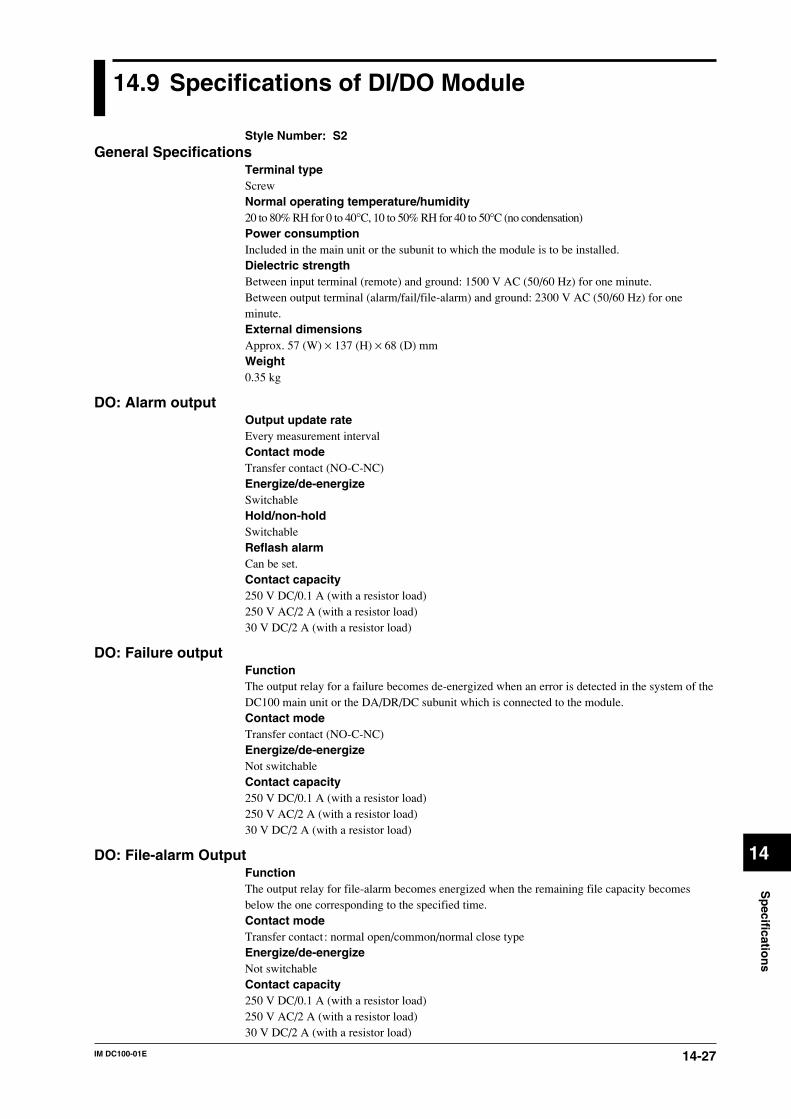
14-27IM DC100-01E
Sp
ecification
s
14
14.9 Specifications of DI/DO Module
Style Number: S2General Specifications
Terminal typeScrewNormal operating temperature/humidity20 to 80% RH for 0 to 40°C, 10 to 50% RH for 40 to 50°C (no condensation)Power consumptionIncluded in the main unit or the subunit to which the module is to be installed.Dielectric strengthBetween input terminal (remote) and ground: 1500 V AC (50/60 Hz) for one minute.Between output terminal (alarm/fail/file-alarm) and ground: 2300 V AC (50/60 Hz) for oneminute.External dimensionsApprox. 57 (W) × 137 (H) × 68 (D) mmWeight0.35 kg
DO: Alarm outputOutput update rateEvery measurement intervalContact modeTransfer contact (NO-C-NC)Energize/de-energizeSwitchableHold/non-holdSwitchableReflash alarmCan be set.Contact capacity250 V DC/0.1 A (with a resistor load)250 V AC/2 A (with a resistor load)30 V DC/2 A (with a resistor load)
DO: Failure outputFunctionThe output relay for a failure becomes de-energized when an error is detected in the system of theDC100 main unit or the DA/DR/DC subunit which is connected to the module.Contact modeTransfer contact (NO-C-NC)Energize/de-energizeNot switchableContact capacity250 V DC/0.1 A (with a resistor load)250 V AC/2 A (with a resistor load)30 V DC/2 A (with a resistor load)
DO: File-alarm OutputFunctionThe output relay for file-alarm becomes energized when the remaining file capacity becomesbelow the one corresponding to the specified time.Contact modeTransfer contact: normal open/common/normal close typeEnergize/de-energizeNot switchableContact capacity250 V DC/0.1 A (with a resistor load)250 V AC/2 A (with a resistor load)30 V DC/2 A (with a resistor load)

14-28 IM DC100-01E
DI: Remote control of data saving functionsFunctionThe following functions can be controlled by contact input:- alarm acknowledge;- alarm reset;- timer reset;- message display;- starting/stopping/clearing/resetting computation;- starting of writing of measured/computed sata;- suspending/resuming of writing of measured/computed data;- trigger to start of writing of measured/computed data;- writing of measured/computed data for one screen;- copying of measured/computed data onto a floppy disk;- reading of setting data.Input signalNo voltage contact, open-collector driven by a TTL or transistorRated voltage:0 to 5 V DC (input impedance:4.7 kΩ, 5 V DC pull up)Maximum input voltage (allowable range)–2 to 7 V DCInput conditions• ON voltage:0.5 V max. (30 mA DC)• Leakage current at OFF state:0.25 mA max.Duration of input signalOne second or longer (input signal detection interval:approx. 0.5 seconds)
14.9 Specifications of DI/DO Module
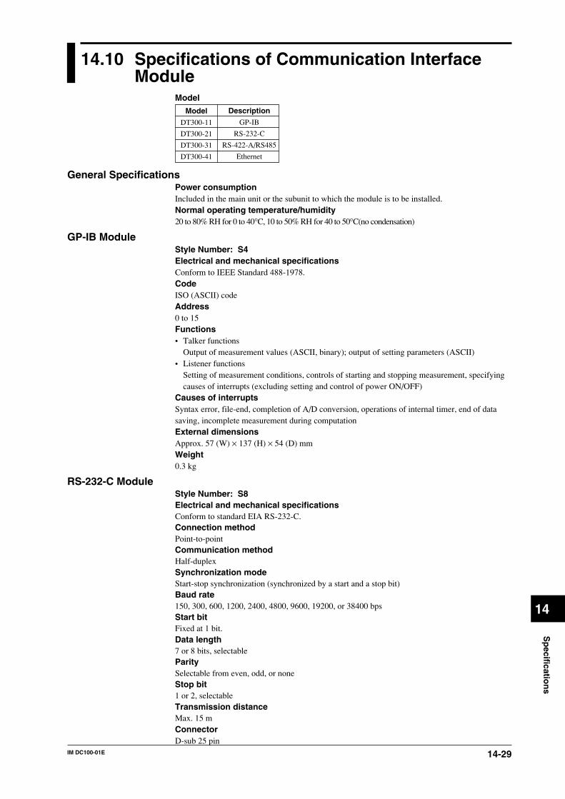
14-29IM DC100-01E
Sp
ecification
s
14
14.10 Specifications of Communication InterfaceModule
ModelDescription
GP-IB
RS-232-C
RS-422-A/RS485
Ethernet
Model
DT300-11
DT300-21
DT300-31
DT300-41
General SpecificationsPower consumptionIncluded in the main unit or the subunit to which the module is to be installed.Normal operating temperature/humidity20 to 80% RH for 0 to 40°C, 10 to 50% RH for 40 to 50°C(no condensation)
GP-IB ModuleStyle Number: S4Electrical and mechanical specificationsConform to IEEE Standard 488-1978.CodeISO (ASCII) codeAddress0 to 15Functions• Talker functions
Output of measurement values (ASCII, binary); output of setting parameters (ASCII)• Listener functions
Setting of measurement conditions, controls of starting and stopping measurement, specifyingcauses of interrupts (excluding setting and control of power ON/OFF)
Causes of interruptsSyntax error, file-end, completion of A/D conversion, operations of internal timer, end of datasaving, incomplete measurement during computationExternal dimensionsApprox. 57 (W) × 137 (H) × 54 (D) mmWeight0.3 kg
RS-232-C ModuleStyle Number: S8Electrical and mechanical specificationsConform to standard EIA RS-232-C.Connection methodPoint-to-pointCommunication methodHalf-duplexSynchronization modeStart-stop synchronization (synchronized by a start and a stop bit)Baud rate150, 300, 600, 1200, 2400, 4800, 9600, 19200, or 38400 bpsStart bitFixed at 1 bit.Data length7 or 8 bits, selectableParitySelectable from even, odd, or noneStop bit1 or 2, selectableTransmission distanceMax. 15 mConnectorD-sub 25 pin
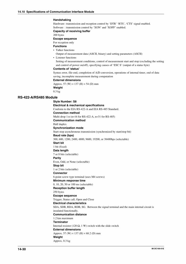
14-30 IM DC100-01E
HandshakingHardware : transmission and reception control by ‘DTR’ ‘RTS’, ‘CTS’ signal enabled.Software : transmission control by ‘XON’ and ‘XOFF’ enabled.Capacity of receiving buffer200 bytesEscape sequenceFor reception onlyFunctions• Talker functions
Output of measurement data (ASCII, binary) and setting parameters (ASCII)• Listener functions
Setting of measurement conditions, control of measurement start and stop (excluding the settingand control of power on/off), specifying causes of ‘ESC S’ (output of a status byte)
Contents of ‘status’Syntax error, file-end, completion of A/D conversion, operations of internal timer, end of datasaving, incomplete measurement during computationExternal dimensionsApprox. 57 (W) × 137 (H) × 54 (D) mmWeight0.3 kg
RS-422-A/RS485 ModuleStyle Number: S8Electrical & mechanical specificationsConform to the EIA RS-422-A and EIA RS-485 Standard.Connection methodMulti-drop 1:n (n=16 for RS-422-A, n=31 for RS-485)Communication methodHalf duplexSynchronization modeStart-stop asynchronous transmission (synchronized by start/stop bit)Baud rate (bps)300, 600, 1200, 2400, 4800, 9600, 19200, or 38400bps (selectable)Start bit1 bit (fixed)Data length7 or 8 bits (selectable)ParityEven, Odd, or None (selectable)Stop bit1 or 2 bits (selectable)Connector6-point screw type terminal (uses M4 screws)Minimum response time0, 10, 20, 50 or 100 ms (selectable)Reception buffer length250 bytesEscape sequenceTrigger, Status call, Open and CloseElectrical characteristicsSDA, SDB, RDA, RDB, SG. Between the signal terminal and the main internal circuit isinsulated functionally.Communication distance1.2 km maximumTerminatorInternal resistor (120 Ω, 1 W) switch with the slide switchExternal dimensionsApprox. 57 (W) × 137 (H) × 68.2 (D) mmWeightApprox. 0.3 kg
14.10 Specifications of Communication Interface Module
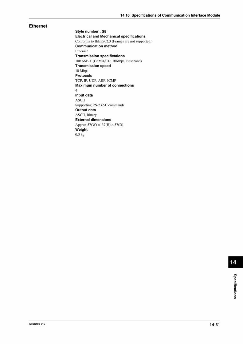
14-31IM DC100-01E
Sp
ecification
s
14
EthernetStyle number : S8Electrical and Mechanical specificationsConforms to IEEE802.3 (Frames are not supported.)Communication methodEthernetTransmission specifications10BASE-T (CSMA/CD, 10Mbps, Baseband)Transmission speed10 MbpsProtocolsTCP, IP, UDP, ARP, ICMPMaximum number of connections4Input dataASCIISupporting RS-232-C commandsOutput dataASCII, BinaryExternal dimensionsApprox 57(W) ×137(H) × 57(D)Weight0.3 kg
14.10 Specifications of Communication Interface Module
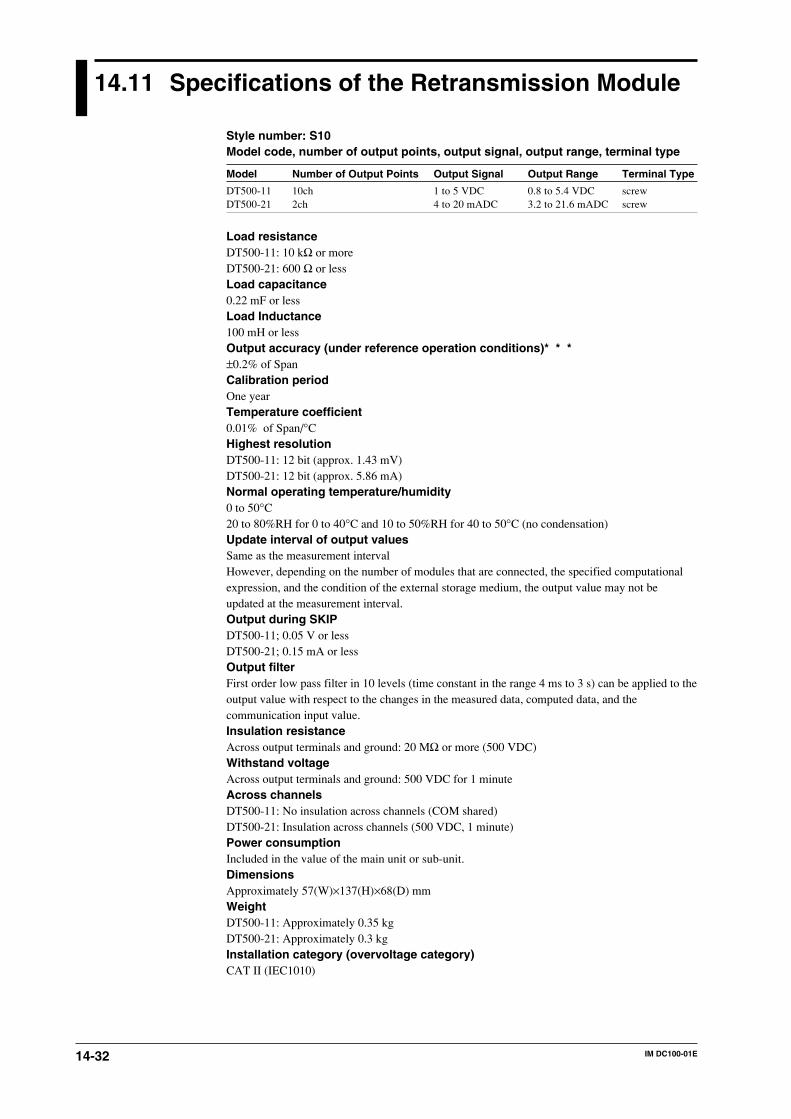
14-32 IM DC100-01E
14.11 Specifications of the Retransmission Module
Style number: S10Model code, number of output points, output signal, output range, terminal type
Model Number of Output Points Output Signal Output Range Terminal Type
DT500-11 10ch 1 to 5 VDC 0.8 to 5.4 VDC screwDT500-21 2ch 4 to 20 mADC 3.2 to 21.6 mADC screw
Load resistanceDT500-11: 10 kΩ or moreDT500-21: 600 Ω or lessLoad capacitance0.22 mF or lessLoad Inductance100 mH or lessOutput accuracy (under reference operation conditions)* * *±0.2% of SpanCalibration periodOne yearTemperature coefficient0.01% of Span/°CHighest resolutionDT500-11: 12 bit (approx. 1.43 mV)DT500-21: 12 bit (approx. 5.86 mA)Normal operating temperature/humidity0 to 50°C20 to 80%RH for 0 to 40°C and 10 to 50%RH for 40 to 50°C (no condensation)Update interval of output valuesSame as the measurement intervalHowever, depending on the number of modules that are connected, the specified computationalexpression, and the condition of the external storage medium, the output value may not beupdated at the measurement interval.Output during SKIPDT500-11; 0.05 V or lessDT500-21; 0.15 mA or lessOutput filterFirst order low pass filter in 10 levels (time constant in the range 4 ms to 3 s) can be applied to theoutput value with respect to the changes in the measured data, computed data, and thecommunication input value.Insulation resistanceAcross output terminals and ground: 20 MΩ or more (500 VDC)Withstand voltageAcross output terminals and ground: 500 VDC for 1 minuteAcross channelsDT500-11: No insulation across channels (COM shared)DT500-21: Insulation across channels (500 VDC, 1 minute)Power consumptionIncluded in the value of the main unit or sub-unit.DimensionsApproximately 57(W)×137(H)×68(D) mmWeightDT500-11: Approximately 0.35 kgDT500-21: Approximately 0.3 kgInstallation category (overvoltage category)CAT II (IEC1010)
14-33IM DC100-01E
Sp
ecification
s
14
14.12 Specifications of Extension Module andExtension Base
Style Number: S5ModelExtension module: DV100-011Extension base: DV100-012Units to which extension modules are connectedDS400/DS600Input modules connectable to an extension baseUniversal input modules: DU100-11 or DU100-12, 10 channelsDCV/TC/DI input modules: DU200-11 or DU200-12, 10 channelsMaximum mountable number of extension modulesOne each on a subunitMaximum connectable number of extension basesUp to three to each extension module. It is not possible, however, to wire extension bases in sucha manner that the total number of modules already mounted on the subunit and the extensionbases being wired exceeds the maximum number of modules allowed for mounting on the sub-unit.Overall length of wiring30 m maximum(The maximum overall length of cable measured from the extension module to the farthestextension base)Normal operating temperature/humidity range-10˚ to 60˚C20 to 80% RH for an ambient temperature range of -10˚ to 40˚C; 10 to 50% RH for 40˚ to 50˚C; 5to 30% RH for 50˚ to 60˚C (no condensation)Insulation resistanceDepends on the input module installed.Withstanding voltageDepends on the input module installed.Power consumptionIncluded in the value of a system's installed main unit or subunitDimensionsExtension module: Approx. 57 (W) × 137 (H) × 49.5 (D) mm (The dimensions do not include the
support feet.)Extension base: Approx. 114.8 (W) x 152.7 (H) x 43.7 D mm (The dimensions do not include
the support feet.)Approx. 114.8 (W) x 171.5 (H) x 143.3 (D) mm (The dimensions include thesupport feet.)
WeightExtension module: Approx. 176 gExtension base: Approx. 345 g
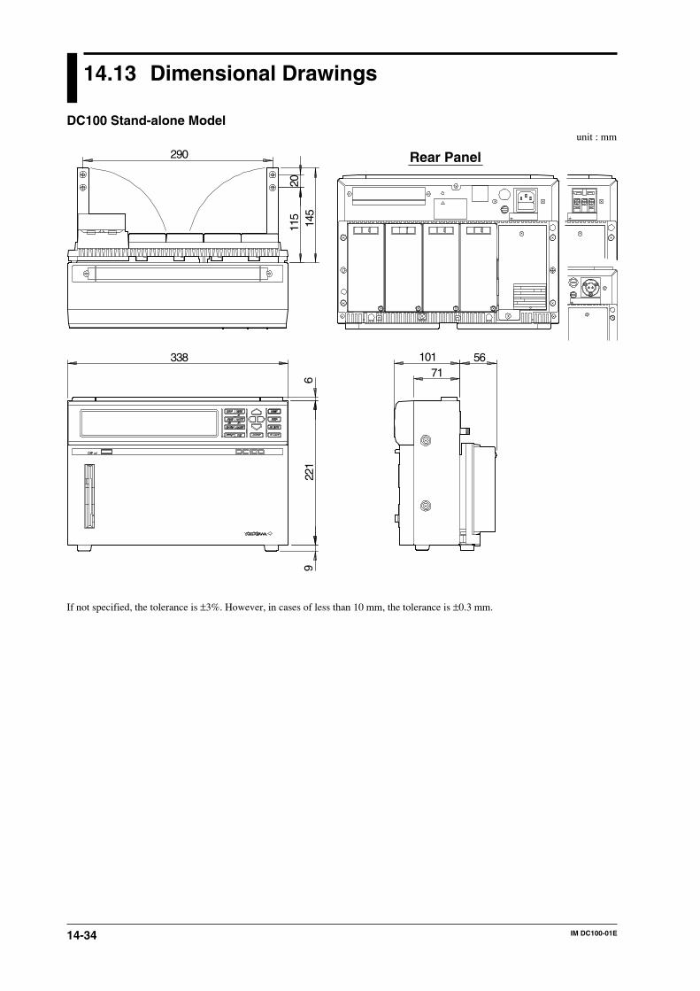
14-34 IM DC100-01E
14.13 Dimensional Drawings
DC100 Stand-alone Model
Rear Panel
unit : mm
If not specified, the tolerance is ±3%. However, in cases of less than 10 mm, the tolerance is ±0.3 mm.
145
115
20
290
33871
101 56
622
19

14-35IM DC100-01E
Sp
ecification
s
14
DC100 Expandable Model
Rear Panelunit : mm
If not specified, the tolerance is ±3%. However, in cases of less than 10 mm, the tolerance is ±0.3 mm.
145
115
20
290
33871
101 566
221
9
14.13 Dimensional Drawings
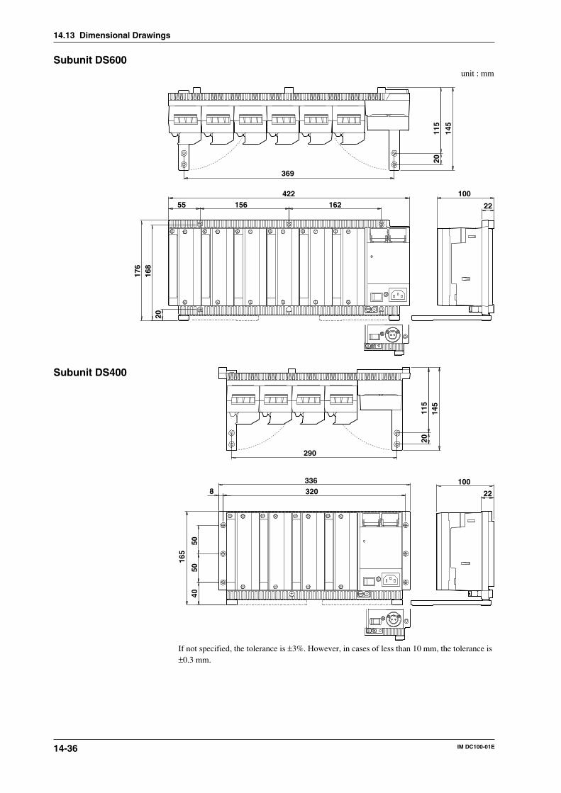
14-36 IM DC100-01E
Subunit DS600
156
168
20
100422
145
2216255
176
115
369
20
unit : mm
Subunit DS400
165
40
100336
145
223208
5050
115
290
20
If not specified, the tolerance is ±3%. However, in cases of less than 10 mm, the tolerance is±0.3 mm.
14.13 Dimensional Drawings
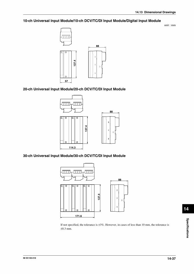
14-37IM DC100-01E
Sp
ecification
s
14
10-ch Universal Input Module/10-ch DCV/TC/DI Input Module/Digital Input Moduleunit : mm
137.
4
88
57
20-ch Universal Input Module/20-ch DCV/TC/DI Input Module
114.3
137.
4
88
30-ch Universal Input Module/30-ch DCV/TC/DI Input Module
171.6
137.
4
88
If not specified, the tolerance is ±3%. However, in cases of less than 10 mm, the tolerance is±0.3 mm.
14.13 Dimensional Drawings
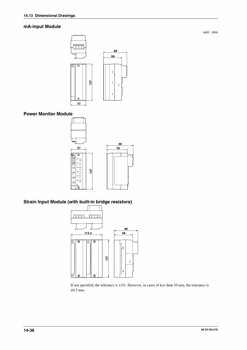
14-38 IM DC100-01E
mA-input Moduleunit : mm
57
88
68
137
Power Monitor Module
5799
78
137
Strain Input Module (with built-in bridge resistors)
114.3 6888
137
If not specified, the tolerance is ±3%. However, in cases of less than 10 mm, the tolerance is±0.3 mm.
14.13 Dimensional Drawings

14-39IM DC100-01E
Sp
ecification
s
14
Strain Input Module (with NDIS terminals)unit : mm
114.3 5777
137
Pulse Input Module
57
6848
137
Digital input Module
137.
4
88
57
If not specified, the tolerance is ±3%. However, in cases of less than 10 mm, the tolerance is±0.3 mm.
14.13 Dimensional Drawings
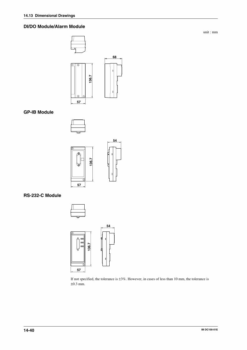
14-40 IM DC100-01E
DI/DO Module/Alarm Moduleunit : mm
136.
7
68
57
GP-IB Module
136.
7
54
57
RS-232-C Module
136.
7
54
57
If not specified, the tolerance is ±3%. However, in cases of less than 10 mm, the tolerance is±0.3 mm.
14.13 Dimensional Drawings
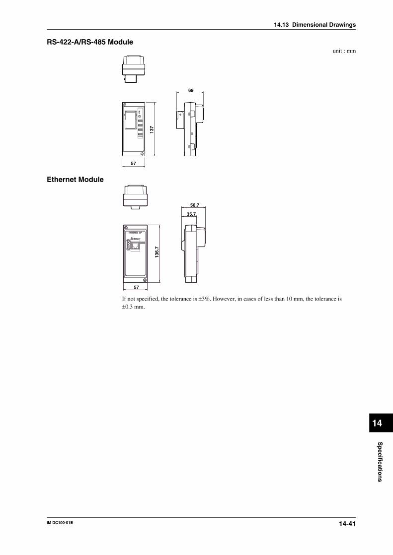
14-41IM DC100-01E
Sp
ecification
s
14
14.13 Dimensional Drawings
RS-422-A/RS-485 Moduleunit : mm
57
69
137
Ethernet Module
57
35.7
56.7
136.
7
If not specified, the tolerance is ±3%. However, in cases of less than 10 mm, the tolerance is ±0.3 mm.
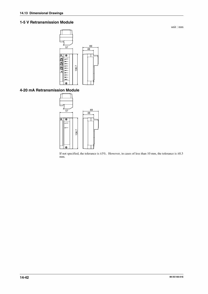
14-42 IM DC100-01E
1-5 V Retransmission Moduleunit : mm
57 6948
136.
7
4-20 mA Retransmission Module
57 6948
136.
7
If not specified, the tolerance is ±3%. However, in cases of less than 10 mm, the tolerance is ±0.3mm.
14.13 Dimensional Drawings
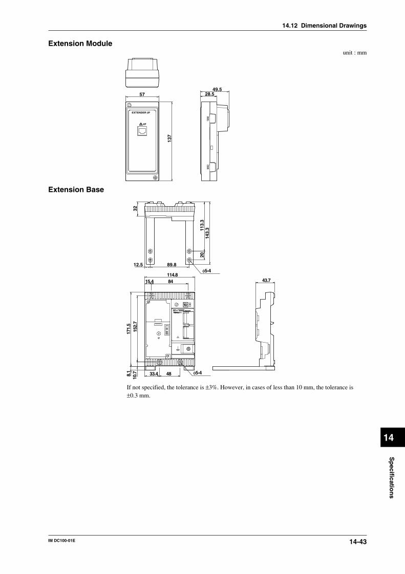
14-43IM DC100-01E
Sp
ecification
s
14
14.12 Dimensional Drawings
Extension Moduleunit : mm
5749.5
28.5
137
EXTENDER I/F
I/F
Extension Base
89.812.5
114.884 43.7
4833.4 φ5-4
φ5-4
15.4
3217
1.5
8.1
10.7
152.
7
113.
314
3.3
20
If not specified, the tolerance is ±3%. However, in cases of less than 10 mm, the tolerance is±0.3 mm.
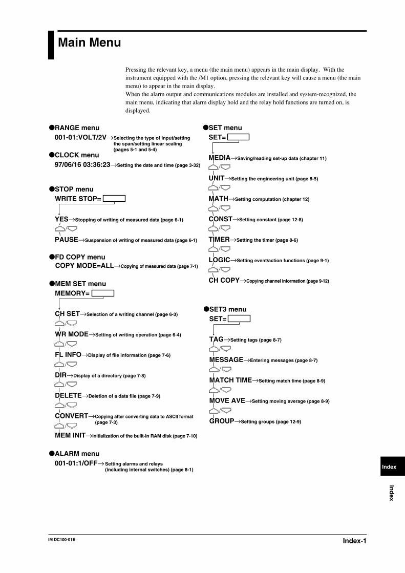
Index-1IM DC100-01E
Ind
ex
Index
Main Menu
Pressing the relevant key, a menu (the main menu) appears in the main display. With theinstrument equipped with the /M1 option, pressing the relevant key will cause a menu (the mainmenu) to appear in the main display.When the alarm output and communications modules are installed and system-recognized, themain menu, indicating that alarm display hold and the relay hold functions are turned on, isdisplayed.
SET=
TAG→Setting tags (page 8-7)
MESSAGE→Entering messages (page 8-7)
MATCH TIME→Setting match time (page 8-9)
MOVE AVE→Setting moving average (page 8-9)
GROUP→Setting groups (page 12-9)
SET3 menu
001-01:VOLT/2V→RANGE menu
Selecting the type of input/setting the span/setting linear scaling (pages 5-1 and 5-4)
97/06/16 03:36:23→Setting the date and time (page 3-32)
CLOCK menu
001-01:1/OFF→ALARM menu
Setting alarms and relays (including internal switches) (page 8-1)
SET=
MEDIA→Saving/reading set-up data (chapter 11)
UNIT→Setting the engineering unit (page 8-5)
MATH→Setting computation (chapter 12)
CONST→Setting constant (page 12-8)
TIMER→Setting the timer (page 8-6)
LOGIC→Setting event/action functions (page 9-1)
CH COPY→Copying channel information (page 9-12)
SET menu
MEMORY=
CH SET→Selection of a writing channel (page 6-3)
WR MODE→Setting of writing operation (page 6-4)
FL INFO→Display of file information (page 7-6)
DIR→Display of a directory (page 7-8)
DELETE→Deletion of a data file (page 7-9)
CONVERT→Copying after converting data to ASCII format (page 7-3)
MEM INIT→Initialization of the built-in RAM disk (page 7-10)
MEM SET menu
WRITE STOP=
YES→Stopping of writing of measured data (page 6-1)
PAUSE→Suspension of writing of measured data (page 6-1)
STOP menu
FD COPY menuCOPY MODE=ALL→Copying of measured data (page 7-1)
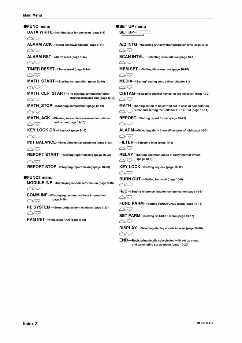
IM DC100-01EIndex-2
DATA WRITE→Writing data for one scan (page 6-1)
ALARM ACK→Alarm acknowledgment (page 9-14)
ALARM RST→Alarm reset (page 9-14)
TIMER RESET→Timer reset (page 9-14)
MATH_START→Starting computation (page 12-10)
MATH_CLR_START→
MATH_STOP→Stopping computation (page 12-10)
MATH_ACK→Clearing incomplete measurement status indication (page 12-10)
KEY LOCK ON→Keylock (page 9-14)
INIT BALANCE→Executing initial balancing (page 5-12)
REPORT START→Starting report making (page 10-23)
REPORT STOP→Stopping report making (page 10-23)
FUNC menu
MODULE INF→Displaying module information (page 9-16)
COMM INF→Displaying communications information (page 9-16)
RE SYSTEM→Structuring system modules (page 3-27)
RAM INIT→Initializing RAM (page 9-16)
FUNC3 menu
SET UP=
A/D INTG→Selecting A/D converter integration time (page 10-3)
SCAN INTVL→Selecting scan interval (page 10-1)
MEM SET→Setting file alarm time (page 10-10)
MEDIA→Saving/reading set-up data (chapter 11)
CH/TAG→Selecting channel number or tag indication (page 10-2)
MATH→Setting action to be carried out in case of computation error and setting the units for TLOG.SUM (page 12-14)
REPORT→Setting report format (page 10-23)
ALARM→Selecting alarm interval/hysteresis/hold (page 10-3)
FILTER→Selecting filter (page 10-3)
RELAY→Setting operation mode of relay/internal switch(page 10-5)
KEY LOCK→Setting keylock (page 10-12)
BURN OUT→Setting burn-out (page 10-8)
RJC→Setting reference junction compensation (page 10-8)
FUNC PARM→Setting FUNC/FUNC3 menu (page 10-14)
SET PARM→Setting SET/SET3 menu (page 10-17)
DISPLAY→Selecting display update interval (page 10-20)
END→Registering details set/selected with set up menu,and terminating set up menu (page 10-20)
SET UP menu
Re-starting computation after clearing computed data (page 12-10)
Main Menu
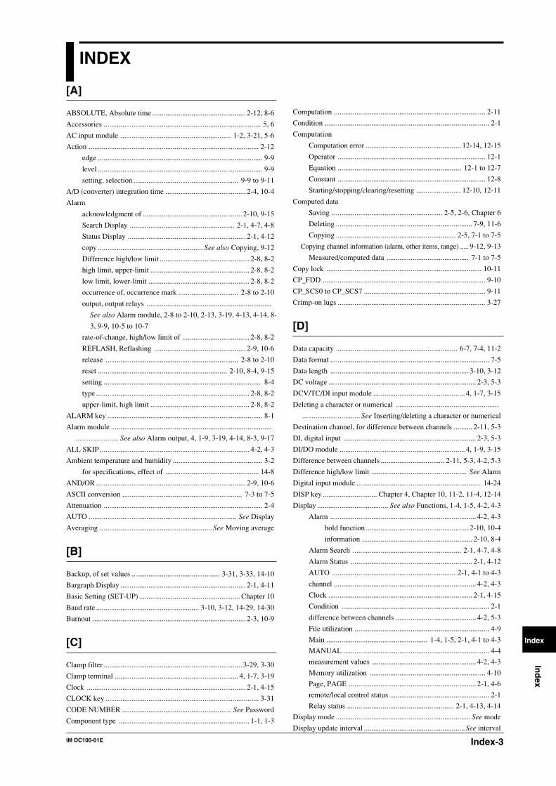
Index-3IM DC100-01E
Ind
ex
Index
INDEX
[A]
ABSOLUTE, Absolute time .................................................. 2-12, 8-6
Accessories .................................................................................... 5, 6
AC input module ........................................................... 1-2, 3-21, 5-6
Action ........................................................................................... 2-12
edge ........................................................................................ 9-9
level ........................................................................................ 9-9
setting, selection ........................................................ 9-9 to 9-11
A/D (converter) integration time ........................................... 2-4, 10-4
Alarm
acknowledgment of ..................................................... 2-10, 9-15
Search Display ........................................................ 2-1, 4-7, 4-8
Status Display ............................................................... 2-1, 4-12
copy ........................................................ See also Copying, 9-12
Difference high/low limit ................................................ 2-8, 8-2
high limit, upper-limit ..................................................... 2-8, 8-2
low limit, lower-limit ...................................................... 2-8, 8-2
occurrence of, occurrence mark ................................ 2-8 to 2-10
output, output relays ...................................................................
See also Alarm module, 2-8 to 2-10, 2-13, 3-19, 4-13, 4-14, 8-
3, 9-9, 10-5 to 10-7
rate-of-change, high/low limit of .................................... 2-8, 8-2
REFLASH, Reflashing ................................................. 2-9, 10-6
release ....................................................................... 2-8 to 2-10
reset ..................................................................... 2-10, 8-4, 9-15
setting .................................................................................... 8-4
type .................................................................................. 2-8, 8-2
upper-limit, high limit ..................................................... 2-8, 8-2
ALARM key ................................................................................... 8-1
Alarm module ......................................................................................
....................... See also Alarm output, 4, 1-9, 3-19, 4-14, 8-3, 9-17
ALL SKIP ................................................................................ 4-2, 4-3
Ambient temperature and humidity ................................................ 3-2
for specifications, effect of .................................................. 14-8
AND/OR ................................................................................ 2-9, 10-6
ASCII conversion ................................................................ 7-3 to 7-5
Attenuation ..................................................................................... 2-4
AUTO ............................................................................... See Display
Averaging ............................................................ See Moving average
[B]
Backup, of set values ............................................... 3-31, 3-33, 14-10
Bargraph Display ................................................................... 2-1, 4-11
Basic Setting (SET-UP) ...................................................... Chapter 10
Baud rate ....................................................... 3-10, 3-12, 14-29, 14-30
Burnout .................................................................................. 2-3, 10-9
[C]
Clamp filter .......................................................................... 3-29, 3-30
Clamp terminal .................................................................. 4, 1-7, 3-19
Clock ..................................................................................... 2-1, 4-15
CLOCK key .................................................................................. 3-31
CODE NUMBER .......................................................... See Password
Component type ...................................................................... 1-1, 1-3
Computation ................................................................................. 2-11
Condition ........................................................................................ 2-1
Computation
Computation error ................................................... 12-14, 12-15
Operator ............................................................................... 12-1
Equation .................................................................. 12-1 to 12-7
Constant ............................................................................... 12-8
Starting/stopping/clearing/resetting ........................ 12-10, 12-11
Computed data
Saving ........................................................... 2-5, 2-6, Chapter 6
Deleting ......................................................................... 7-9, 11-6
Copying ................................................................ 2-5, 7-1 to 7-5
Copying channel information (alarm, other items, range) ..... 9-12, 9-13
Measured/computed data ............................................ 7-1 to 7-5
Copy lock ................................................................................... 10-11
CP_FDD ....................................................................................... 9-10
CP_SCS0 to CP_SCS7 ................................................................. 9-11
Crimp-on lugs ............................................................................... 3-27
[D]
Data capacity ................................................................. 6-7, 7-4, 11-2
Data format ..................................................................................... 7-5
Data length .......................................................................... 3-10, 3-12
DC voltage ............................................................................... 2-3, 5-3
DCV/TC/DI input module ................................................. 4, 1-7, 3-15
Deleting a character or numerical .......................................................
............................... See Inserting/deleting a character or numerical
Destination channel, for difference between channels .......... 2-11, 5-3
DI, digital input ....................................................................... 2-3, 5-3
DI/DO module ................................................................... 4, 1-9, 3-15
Difference between channels .................................. 2-11, 5-3, 4-2, 5-3
Difference high/low limit ................................................... See Alarm
Digital input module .................................................................. 14-24
DISP key ............................. Chapter 4, Chapter 10, 11-2, 11-4, 12-14
Display ...................................... See also Functions, 1-4, 1-5, 4-2, 4-3
Alarm .............................................................................. 4-2, 4-3
hold function ....................................................... 2-10, 10-4
information ........................................................... 2-10, 8-4
Alarm Search .......................................................... 2-1, 4-7, 4-8
Alarm Status ................................................................. 2-1, 4-12
AUTO .................................................................. 2-1, 4-1 to 4-3
channel ............................................................................ 4-2, 4-3
Clock ............................................................................. 2-1, 4-15
Condition ............................................................................... 2-1
difference between channels ........................................... 4-2, 5-3
File utilization ........................................................................ 4-9
Main ...................................................... 1-4, 1-5, 2-1, 4-1 to 4-3
MANUAL .............................................................................. 4-4
measurement values ........................................................ 4-2, 4-3
Memory utilization .............................................................. 4-10
Page, PAGE .................................................................... 2-1, 4-6
remote/local control status ..................................................... 2-1
Relay status ......................................................... 2-1, 4-13, 4-14
Display mode ........................................................................ See mode
Display update interval ......................................................See interval
IM DC100-01EIndex-4
[E]
Edge action ..................................................................................... 9-9
Engineering unit
display ............................................................................. 4-2, 4-3
Setting .................................................................................... 8-7
Ethernet
Setting .................................................................................. 3-13
Specification ...................................................................... 14-31
Event, event/action functions ................................... 2-12, 9-1 to 9-11
Extension base .............................................................................. 3-23
Extension module ......................................................................... 3-23
External in/output ......................................................................... 2-13
External RJC (EXT) ............................................................... See RJC
[F]
Fail (failure) output ............................................................. 2-12, 3-19
FD COPY key ................................................................................ 7-1
Ferrite core .................................................................. 3-9, 3-11, 3-43
File alarm ............................................................................. 2-7, 10-11
File alarm output ................................................................. 2-13, 3-19
File cancellation .................................................................. 2-7, 10-11
File end ........................................................................................... 9-9
Filename setting ...................................................................... 2-6, 6-5
File operation .................................................... Chapter 7, Chapter 11
File overwriting ................................................................... 2-6, 10-11
File utilization display .................................................................... 4-9
Filter
Input .............................................................................. 2-4, 10-4
Noise .................................................................................... 3-38
First channel ................................................................................... 5-2
Flag ...................................................................................... 9-11, 12-2
Floppy disk
Directory display .................................................................. 11-5
Formatting ............................................................................ 11-9
Handling ............................................................................... 1-12
Information display .............................................................. 11-8
FUNC key ......................... 3-30, 6-1, 9-14, 9-16, 10-25, 12-10, 12-13
Functions
Action ................................................................................... 2-12
Alarm ........................................................................ 2-8 to 2-10
Alarm display hold ...................................................... 2-10, 10-4
Computation ......................................................................... 2-17
Data saving ..................................................................... 2-5, 2-6
Display ................................................................................... 2-1
Event/action ..................................................... 2-12, 9-1 to 9-11
External in/output ................................................................ 2-12
Key-lock, keylock ................................ 2-12, 9-15, 10-12, 10-13
Match Time function .................................................... 8-10, 9-9
Measurement input ......................................................... 2-3, 2-4
Relay hold ................... See also HOLD/NON-HOLD, 2-8, 10-7
Function Grounding Terminal, function-ground terminal, .................
............................................................................. 7, 3-9, 3-11, 3-43
Fuse ................................................................................................... 5
holder ................................................................................... 13-2
replacement of ...................................................................... 13-2
[G]
GP-IB interface ...................................................................... 2-14, 3-9
GP-IB module ...................................................................... 4, 1-9, 3-9
Graph ................................................................. See Bargraph display
Grounding, protective grounding ........................................................
.............................................. 7, 3-15, 3-27, 3-28, 3-37, 3-42, 3- 43
Group reset ................................................................................... 9-10
Group setting ................................................................................ 12-9
[H]
Handshake ......................................................................... 3-10, 14-28
High limit alarm ................................................................... See alarm
High resolution RTD .................................................................. 14-12
HOLD/NON-HOLD .............................................................. 2-9, 10-7
Hysteresis .............................................................................. 2-8, 10-4
[I]
Initialization ......................................................................... 7-10, 9-17
Input
channel ............................................................................ 1-2, 1-3
filter ............................................................................... See filter
terminals ........................................................... 1-4, 3-15 to 3-22
type ................................................................... 2, 2-3, 5-1 to 5-3
Inserting/deleting a character or numerical .................................... 8-8
Installation method .............................................................. 3-2 to 3-5
Instrument number ............................................................................ 3
Integration time ......................... See A/D (converter) integration time
Internal RJC ............................................................................ See RJC
Internal switches ................................................ 2-8, 8-3, 10-5 to 10-7
Interval
Display update ............................................................ 2-1, 10-20
for scan (measurement) ................................................. 2-4, 10-1
for rate-of-change alarms .............................................. 2-8, 10-4
INTVL ............................................................................................ 6-6
[J]
[K]
Keepalive ...................................................................................... 3-13
Key-lock (keylock) function ............................................... 2-13, 9-15
setting of ................................................................. 10-12, 10-13
KEY LOCK, KEYLOCK ................................ See Key-lock function
[L]
Last channel .................................................................................... 5-2
Level action .................................................................................... 9-9
Life of lithium battery ....................................................... 3-31, 14-10
Linear scaling ........................................................................ 2-11, 5-5
LOGIC ............................................................................................ 6-6
Logic (LOGIC) box ........................................................................ 9-9
Low limit alarm, lower-limit alarm .................................... See Alarm
INDEX
Index-5IM DC100-01E
Ind
ex
Index
[M]
mA input module ....................................................... 1-7, 3-17, 14-13
MANUAL ........................................................................ See Display
Match Time function
setting of ......................................................................... 8-9, 9-9
Measured data
Saving ........................................................... 2-5, 2-6, Chapter 6
Deleting ......................................................................... 7-9, 11-6
Copying ................................................................ 2-5, 7-1 to 7-5
Measurement input functions .................................................. 2-3, 2-4
Measurement interval ....................................................... See interval
Measurement range ...................................................................... 14-2
MEM SET key ............................................. 6-3, 7-3, 7-6, 7-8 to 7-10
Memory ............................................................................................. 3
Memory utilization display .......................................................... 4-10
Message display .................................................................... 8-8, 9-10
M. FUNC key ................................................................................. 9-9
MODE key ................................................................... Chapter 4, 9-6
Mode
Display ............................................................... 2-1, 4-1 to 4-15
Monitor Display ..................................................................... 2-1
Operation ......................................................... 2-9, 10-5 to 10-7
Model and Suffix Codes ............................................................. 3 to 6
Module information ...................................................................... 9-17
Monitor Display Mode ................................................................... 2-1
Moving average functions ................................................... 2-11, 8-10
number of samples for ................................................ 2-11, 8-10
[N]
Names of parts .................................................. 1-4 to 1-11, 3-4 to 3-8
Name plate ..................................................................................... 3, 4
NO ALARM ........................................................................ 4-7 to 4-9
Noise, countermeasures ................................................... 3-34 to 3-43
[O]
Operating conditions (reference) .................................................. 14-8
Operation panel ....................................................................... 1-4, 1-5
Operation mode .................................................................... See mode
Optional modules ....................................................................... 4, 1-7
alarm module ....................................................................... 2-13
communication interface modules ....................................... 2-14
DI/DO module ..................................................................... 2-13
[P]
Parity ............................................................ 3-10, 3-12, 14-27, 14-28
Parts replacement ......................................................................... 13-1
Password .................................................................. 2-12, 9-15, 10-11
Periodic file
copy ........................................................................................ 7-1
setting .......................................................................... 6-3 to 6-7
START ............................................................................ 6-1, 6-2
STOP ............................................................................... 6-1, 6-2
summary ................................................................................. 2-5
Periodic maintenance ................................................................... 13-1
Power
connector ............................................................... 1-4, 1-5, 3-27
cable (code) ........................................................... 3, 5, 3-1, 3-27
switch .................................................................... 1-4, 1-5, 3-31
terminals ........................................................................ 1-5, 3-28
Power supply voltage .................................................. 2, 4, 3-27, 3-28
Pre trigger ................................................................................ 2-5, 6-6
Protective grounding .................................................... See grounding
Pulse input module ...................................................... 1-2, 3-19, 5-14
[Q]
[R]
Rack mount kit, rack mounting .................................................. 6, 3-3
RAM disk
Directory display .................................................................... 7-8
File information display ......................................................... 7-6
Initialization ......................................................................... 7-10
RANGE key ......................................................................... Chapter 5
Re-failure or re-alarm ........................................ See Alarm reflashing
Reference channel, for difference between channels ............ 2-11, 5-3
Reference junction compensation .......................................... See RJC
REFLASH, Reflashing alarm ................................................ 2-9, 10-6
Registration, of details set/selected with SET UP menu ............ 10-20
RELATIVE, relative time ..................................................... 2-12, 8-6
Relay
for alarm output ......................................................... See Alarm
energizing/de-energizing setting ................................... 2-9, 10-7
Remote control, REMOTE .......................................... 2-13, 3-19, 9-9
Replacement period, for parts ...................................................... 13-1
Report
ON/OFF ............................................................................. 10-23
START ...................................................................... 9-11, 10-27
STOP ......................................................................... 9-11, 10-27
Reset
Alarm ......................................................................... See Alarm
Group ................................................................. See Group reset
Timer .................................................................. See Timer reset
Resistance temperature detector ............................................ See RTD
Retransmission module .......................................................................
............................... 1-2, 1-10, 2-14, 3-6, 3-20, 13-11, 14-32, 14-42
RJC ........................................................................................ 2-3, 10-9
RRJC ..................................................................................... 2-14, 5-3
RS-232C Interface ............................................................... 2-14, 3-10
RS-232C module ............................................................... 4, 1-9, 3-10
RS-422-A/RS-485 Interface ................................................ 2-14, 3-11
RS-422-A/RS-485 module ................................................ 4, 1-6, 3-11
INDEX
IM DC100-01EIndex-6
RST_G01 to RST_G07 ................................................................ 9-10
RTD ......................................................................................... 2-3, 5-3
[S]
Scan interval ..................................................................... See Interval
Screw terminals ................................................ 4, 1-7, 1-8, 3-16, 3-28
SCSI
connecting ............................................................................ 3-25
device ................................................................................... 3-25
ID ....................................................................................... 10-29
SCSI0 to SCSI7 ............................................................................ 9-11
SET key ...............................................................................................
6-10, 8-5 to 8-7, 8-9, 9-1, 9-12, 9-19, Chapter 11, 12-5, 12-8, 12-9
Set-up data
Saving ................................................................. 2-5, 11-1, 11-2
Reading ............................................................... 2-5, 11-3, 11-4
Deleting ....................................................................... 11-6, 11-7
Shunt resistor (resistance) ........................................................ 6, 3-16
SKIP, skipping ............................... 2-3, 4-2, 4-3, 4-5 to 4-7, 4-11, 5-3
Slots ............................................ 3-8, 4-2, 4-3, 4-12, 4-14, 10-6, 10-7
Software ......................................................................................... 3, 6
Span ......................................................................................... 2-4, 5-3
calibrated values of ............................................................ 13-10
START key ..................................................................................... 6-1
Stop bit ......................................................... 3-10, 3-12, 14-27, 14-28
STOP key ....................................................................................... 6-1
Strain balance ............................................................................... 5-10
Strain input module ......................................... 1-2, 3-17, 5-10 to 5-12
Style number ...................................................................................... 2
Sub-display 1, 2 ........................................................ 1-4, 1-5, 2-1, 4-3
Suffix codes ........................................... See Model and Suffix Codes
Symbols
for conventions ......................................................................... 9
for safety ................................................ See also WARNING, 7
System module, recognition of ..................................................... 3-30
[T]
Tag
setting .................................................................... 6-9, 8-8, 10-2
Terminal cover ............................................................................. 3-15
Thermocouple .......................................................................... 2-3, 5-3
Timer ..................................................................................... 2-12, 8-6
Timer reset ................................................................. 2-12, 9-14, 9-15
Trigger ..................................................................................... 2-5, 6-5
Troubleshooting ............................................................................ 13-3
[U]
Unit No. ................................................................ 4-2, 4-3, 4-13, 4-15
Universal input module .................................. 4, 1-2, 1-7, 3-16, 14-11
Upper-limit alarm ............................................................... See Alarm
[V]
Voltage level ................................................................................... 5-3
INDEX
[W]
Warm up ....................................................................................... 3-31
WARNING, for safety precautions ................................................... 7
Wiring ........................................................................................... 3-15
Writing (saving)
auxiliary setting ............................................... 2-7, 10-10, 10-11
channel selection ..................................................... 2-5, 6-3, 6-4
setting ................................................................... 2-5, 6-4 to 6-8
data length .............................................................. 2-5, 6-6
division method ...................................................... 2-5, 6-6
filename setting ...................................................... 2-5, 6-5
trigger ..................................................................... 2-5, 6-5
write mode, saving method .................................... 2-5, 6-4
writing period ......................................................... 2-5, 6-6
start/stop/pause ............................ 2-5, 6-2, 6-9, 6-10, 9-10, 9-11
write data for one scan .......................................... 2-5, 6-2, 9-10
[X]
[Y]
[Z]
Zero position
calibrated values of ............................................................ 13-10