dc to ac converters inverters - elg.uottawa.carhabash/elg4139dctoacconverters.pdf · elg4139: dc to...
TRANSCRIPT
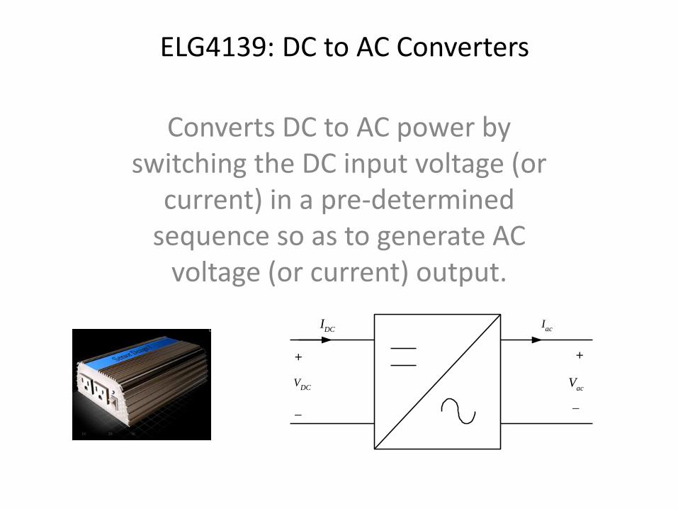
ELG4139: DC to AC Converters
Converts DC to AC power by switching the DC input voltage (or
current) in a pre-determined sequence so as to generate AC
voltage (or current) output.
IDC
Iac
+
VDC V
ac
+
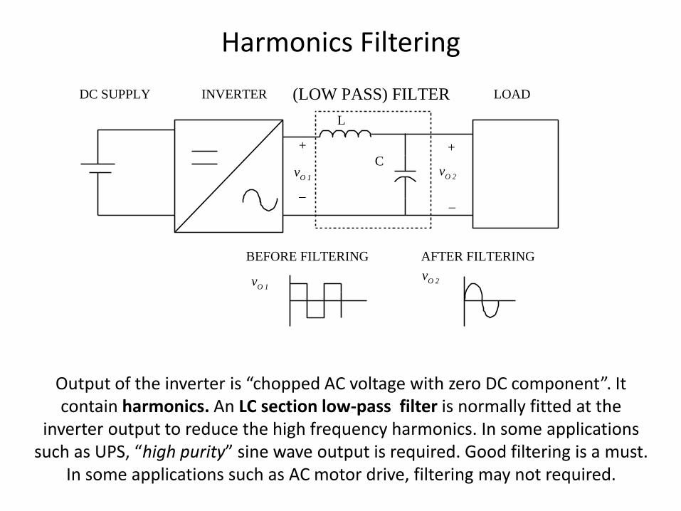
Harmonics Filtering
vO 1
+
L
Cv
O 2
(LOW PASS) FILTER
+
vO 1
vO 2
BEFORE FILTERING AFTER FILTERING
INVERTER LOADDC SUPPLY
Output of the inverter is “chopped AC voltage with zero DC component”. It contain harmonics. An LC section low-pass filter is normally fitted at the
inverter output to reduce the high frequency harmonics. In some applications such as UPS, “high purity” sine wave output is required. Good filtering is a must.
In some applications such as AC motor drive, filtering may not required.

Single Phase Half-Bridge Inverter
Vo
RL
+
VC1
VC2
+
-
+
-
S1
S2
Vdc
2
Vdc
2
Vdc
S1 ON
S2 OFF
S1 OFF
S2 ON
t0G
Also known as the Inverter Leg! Both capacitors have the same value. Thus the DC link is equally
spilt into two. The top and bottom switch has to be complementary. Meaning, If the top switch is closed (ON), the bottom must be OFF,
and vice-versa.

Q1 on, Q2 off, vo = Vs/2
Peak Reverse Voltage of Q2 = Vs

Q1 off, Q2 on, vo = -Vs/2

Single Phase Full Bridge
S1
S4
S3
S2
+
-
G
+
2
dcV
2
dcV
-
2
dcV
2
dcV
dcV
2
dcV
2
dcV
dcV
p
p
p
p2
p2
p2
tw
tw
tw
RGV
GRV '
oV
GRo VVVRG '=
groumd" virtual" is G
LEG R LEG R'
R R'- oV+
dcV
+
-
Single phase full bridge is built from two half-bridge leg. The switching in the second leg is delayed by 180 degrees from the first leg.

Q1-Q2 on, Q3-Q4 off, vo = Vs
+ Vs -

Q3-Q4 on, Q1-Q2 off, vo = -Vs
- Vs +
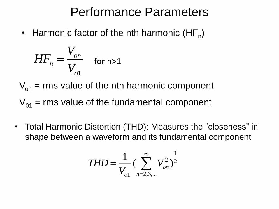
Performance Parameters
• Harmonic factor of the nth harmonic (HFn)
1
onn
o
VHF
V= for n>1
Von = rms value of the nth harmonic component
V01 = rms value of the fundamental component
• Total Harmonic Distortion (THD): Measures the “closeness” in
shape between a waveform and its fundamental component
1
2 2
2,3,...1
1( )on
no
THD VV
=
=

Design Constraints of a Pure Sine wave Inverter
Quantity Details
Voltage Convert 12VDC to 120 VAC
Power Provide 300 W continuous
Efficiency > 90% efficiency
Waveform Pure 60 Hz sinusoidal
Total Harmonic
Distortion
< 5% THD
Physical Dimensions 8” x 4.75” x 2.5”
Cost $175.00

Required Components for Design
Full-bridge
Inverter
Sinusoidal PWM
Controller
Low-pass
Filter
PWM Control
Circuit
Half-bridge
Converter Transformer
12 V DC Input
from vehicle battery)
120 VAC, 60 Hz, 300 W
Output

PWM Controller
• Produces two complementary pulses to control half-bridge transistors.
• Problem:
– Voltage may drop when the input voltage is decreased.
• Solution:
– A feedback network may be added for voltage regulation.

Pulse Width Modulation
Modulating Waveform Carrier waveform
1M
1+
1
0
2
dcV
2
dcV
00t 1t 2t 3t 4t 5t
Triangulation method (Natural sampling). Amplitudes of the triangular wave
(carrier) and sine wave (modulating) are compared to obtain PWM
waveform. Analogue comparator may be used. Basically an analogue
method. Its digital version, known as REGULAR sampling is widely used in
industry.
h x( ) if k x( ) c x( ) 1 if k x( ) c x( ) 1 0( )( )=1
Regular sampling PWM
Sinusoidal modulating
waveform, vm(t)
Carrier, vc(t)t
1 t2
t'1
t'2
t
t
p
p2
)(tvs
pwmv
Regular sampling waveform,

Software Flow Diagram (Dr. Yaroslav Koshka)
Initialize all variables
Count0 = 300 (300 duty cycles)
Has duty cycle been
reached?
Output 1 = high, Output 2 = low
duty cycle table (increment pointer) Output 1 = low, Output 2 = high
300 duty cycle
values?
Decrement Count0 by 1 Duty cycle and sampling period timer
One Sampling
Period? no yes
yes
no
yes no

Low-pass Filter
• 2nd order L-C filter
– Filters to retain a 60
Hz fundamental
frequency
– Few components
– Handle current
– Wind inductor (fine
tune)

PCB Layout

Case Study: Solar System Using Inverters Stand Alone; Simple Grid Tied; Grid Tie with Battery
Solar Schoolhouse and San Mateo College


Simple Grid-Connected System
Solar Array
Inverter Distribution Panel
Utility

Subpanel
Solar AC in from Inverter
Lightning surge arrestor


Stand Alone Residential System
Solar Array
Charge Controller
Battery
DC to AC Inverter
Distribution Panel AC
Distribution Panel DC

Small Stand Alone
System
(to power an office)
Solar Array
Charge Control
Storage: Battery
“Fuel Gauge”
Inverter DC to AC