day 14.2 inter vlan
TRANSCRIPT
Virtual Trunk Protocol
Trunking
• A trunk is a physical and logical connection between two
switches across which network traffic travels.
• In a switched network, a trunk is a point-to-point link that
supports several VLANs.
• The purpose of a trunk is to conserve ports when a link
between two devices that implement VLANs is created.

Trunking
• Trunking bundles multiple virtual links over one physical
link.
• This allows the traffic of several VLANs to travel over a
single cable between the switches.
Trunking
• Trunking protocols were developed to effectively manage
the transfer of frames from different VLANs on a single
physical line.
• Frame tagging has been adopted as the standard trunking
mechanism by the IEEE.

Trunking
• The unique physical link between the two switches is able
to carry traffic for any VLAN.
• Each frame sent on the link is tagged so that it carries the
VLAN ID to identify which VLAN it belongs to.
• The two most common tagging schemes for Ethernet
segments are ISL and 802.1Q:– ISL – A Cisco proprietary protocol
– 802.1Q – An IEEE standard that is the focus of this section
Trunking
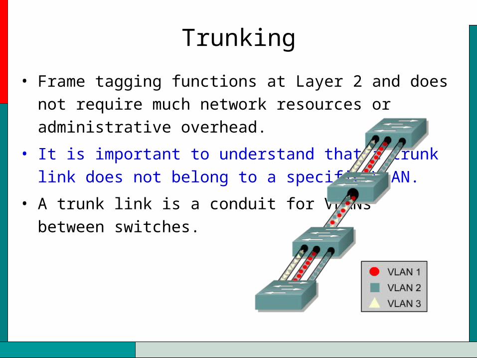
• Frame tagging functions at Layer 2 and does not require
much network resources or administrative overhead.
• It is important to understand that a trunk
link does not belong to a specific VLAN.
• A trunk link is a conduit for VLANs
between switches.
Trunking
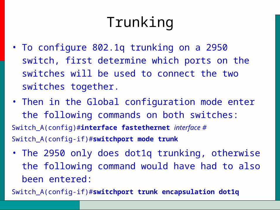
• To configure 802.1q trunking on a 2950 switch, first
determine which ports on the switches will be used to
connect the two switches together.
• Then in the Global configuration mode enter the following
commands on both switches:Switch_A(config)#interface fastethernet interface #
Switch_A(config-if)#switchport mode trunk
• The 2950 only does dot1q trunking, otherwise the following
command would have had to also been entered:Switch_A(config-if)#switchport trunk encapsulation dot1q

Trunking
• To verify that trunking has been configured and verify the settings use the following commands from Privileged EXEC mode of the switch:
show interfaces Fa0/port_num
show interfaces trunk
Virtual Trunking Protocol (VTP)
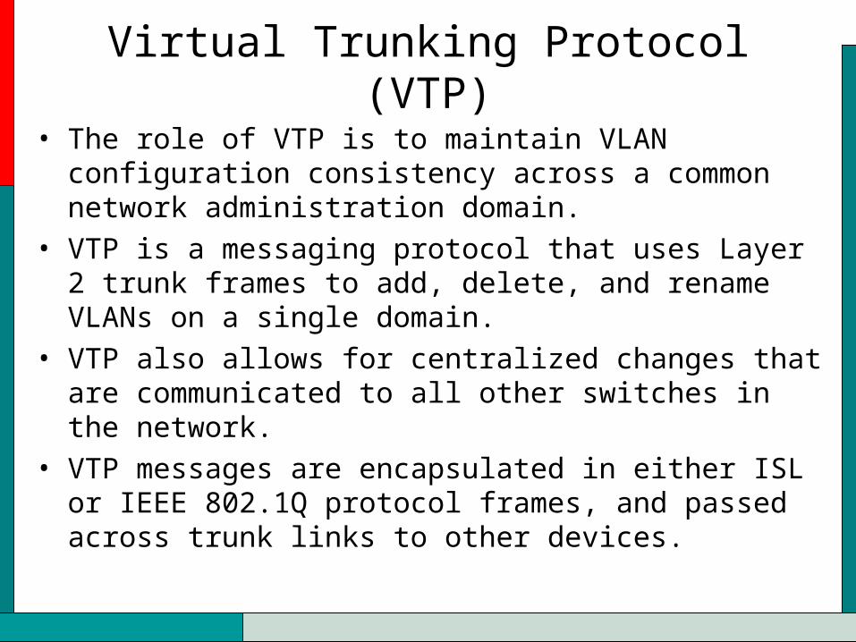
• The role of VTP is to maintain VLAN configuration consistency across a common network administration domain.
• VTP is a messaging protocol that uses Layer 2 trunk frames to add, delete, and rename VLANs on a single domain.
• VTP also allows for centralized changes that are communicated to all other switches in the network.
• VTP messages are encapsulated in either ISL or IEEE 802.1Q protocol frames, and passed across trunk links to other devices.
Virtual Trunking Protocol (VTP)
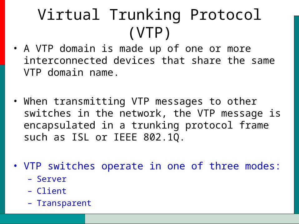
• A VTP domain is made up of one or more interconnected devices that share the same VTP domain name.
• When transmitting VTP messages to other switches in the network, the VTP message is encapsulated in a trunking protocol frame such as ISL or IEEE 802.1Q.
• VTP switches operate in one of three modes:– Server – Client – Transparent

VTP Servers
• VTP servers can create, modify, and delete VLAN and VLAN configuration parameters for the entire domain.
• VTP servers save VLAN configuration information in the switch NVRAM.
• VTP servers send VTP messages out to all trunk ports.

VTP Client
• VTP clients cannot create, modify, or delete VLAN information.
• The only role of VTP clients is to process VLAN changes and send VTP messages out all trunk ports.

VTP Transparent Mode
• Switches in VTP transparent mode forward VTP advertisements but ignore information contained in the message.
• A transparent switch will not modify its database when updates are received, or send out an update that indicates a change in its VLAN status.
• Except for forwarding VTP advertisements, VTP is disabled on a transparent switch.
• Switches in VTP transparent mode can create and remember VLANs, but only of local significance.
• VLANs created in the transparent mode will not be sent to other switches.
VTP Transparent Mode
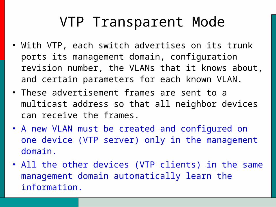
• With VTP, each switch advertises on its trunk ports its management domain, configuration revision number, the VLANs that it knows about, and certain parameters for each known VLAN.
• These advertisement frames are sent to a multicast address so that all neighbor devices can receive the frames.
• A new VLAN must be created and configured on one device (VTP server) only in the management domain.
• All the other devices (VTP clients) in the same management domain automatically learn the information.
VTP Advertisements
• Each advertisement starts as configuration revision number 0.
• As changes are made, the configuration revision number is increased incrementally by one, or n + 1.
• Only the advertisement with the highest revision number is maintained.

VTP ConfigurationSwitch# configure terminalSwitch(config)# vtp mode [ server | client | transparent ]Switch(config)# vtp domain domain-nameSwitch(config)# vtp passwordSwitch(config)# vtp pruningSwitch(config)# exit
Switch(config)# vtp domain ICNDChanging VTP domain name to ICNDSwitch(config)# vtp mode transparentSetting device to VTP TRANSPARENT mode.Switch(config)# exit
Switch#show vtp statusVTP Version : 2Configuration Revision : 0Maximum VLANs supported locally : 64Number of existing VLANs : 17VTP Operating Mode : TransparentVTP Domain Name : ICNDVTP Pruning Mode : DisabledVTP V2 Mode : DisabledVTP Traps Generation : DisabledMD5 digest : 0x7D 0x6E 0x5E 0x3D 0xAF 0xA0 0x2F 0xAAConfiguration last modified by 10.1.1.4 at 3-3-93 20:08:05Switch#

Inter-VLAN Routing
• If a VLAN spans across multiple devices a trunk is used to interconnect the devices.
• A trunk carries traffic for multiple VLANs. – a trunk can connect a switch to another switch– a switch to the inter-VLAN router– a switch to a server with a special NIC installed that supports
trunking.
• Remember that when a host on one VLAN wants to communicate with a host on another, a router must be involved.

Inter-VLAN Routing
• In a traditional situation, a network with four VLANs would require four physical connections between the switch and the external router.
• The router only supports one VLAN per interface.• This does not scale very well.

Inter-VLAN Routing
• Networks with many VLANs must use VLAN trunking to assign multiple VLANs to a single router interface.
• The router can support many logical interfaces on individual physical links through the use of subinterfaces.
• The primary advantage of using a trunk link is a reduction in the number of router and switch ports used.

Inter-VLAN Routing
• A subinterface is a logical interface within a physical interface.
• Each subinterface supports one VLAN, and is assigned one IP address.
• In order to route between VLANs with subinterfaces, a subinterface must be created for each VLAN.
Inter-VLAN Routing
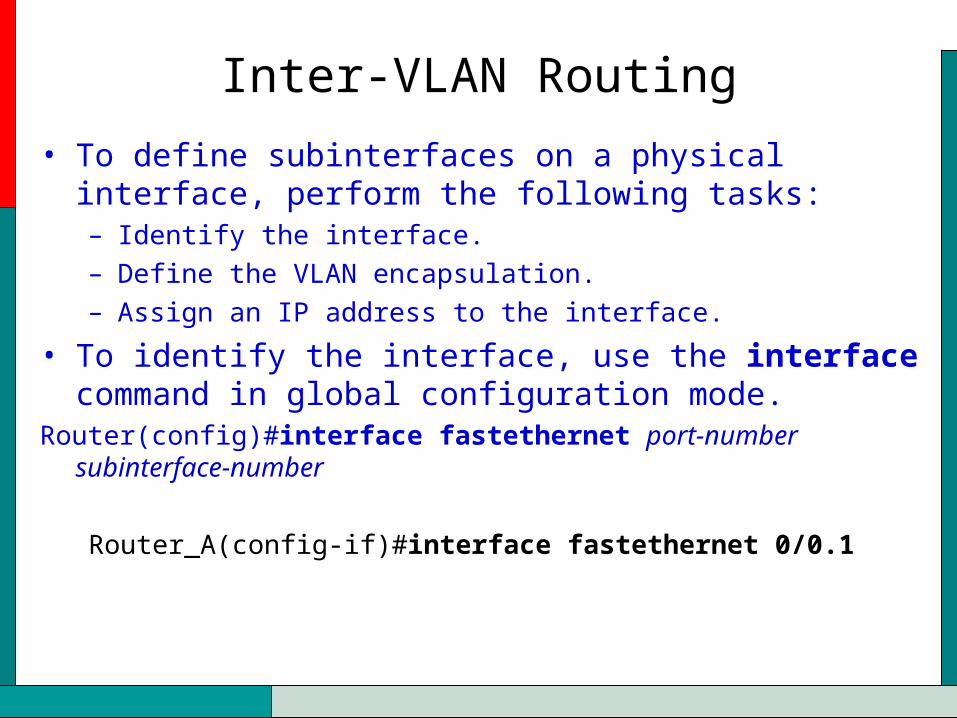
• To define subinterfaces on a physical interface, perform the following tasks: – Identify the interface. – Define the VLAN encapsulation. – Assign an IP address to the interface.
• To identify the interface, use the interface command in global configuration mode.
Router(config)#interface fastethernet port-number subinterface-number
Router_A(config-if)#interface fastethernet 0/0.1
Inter-VLAN Routing
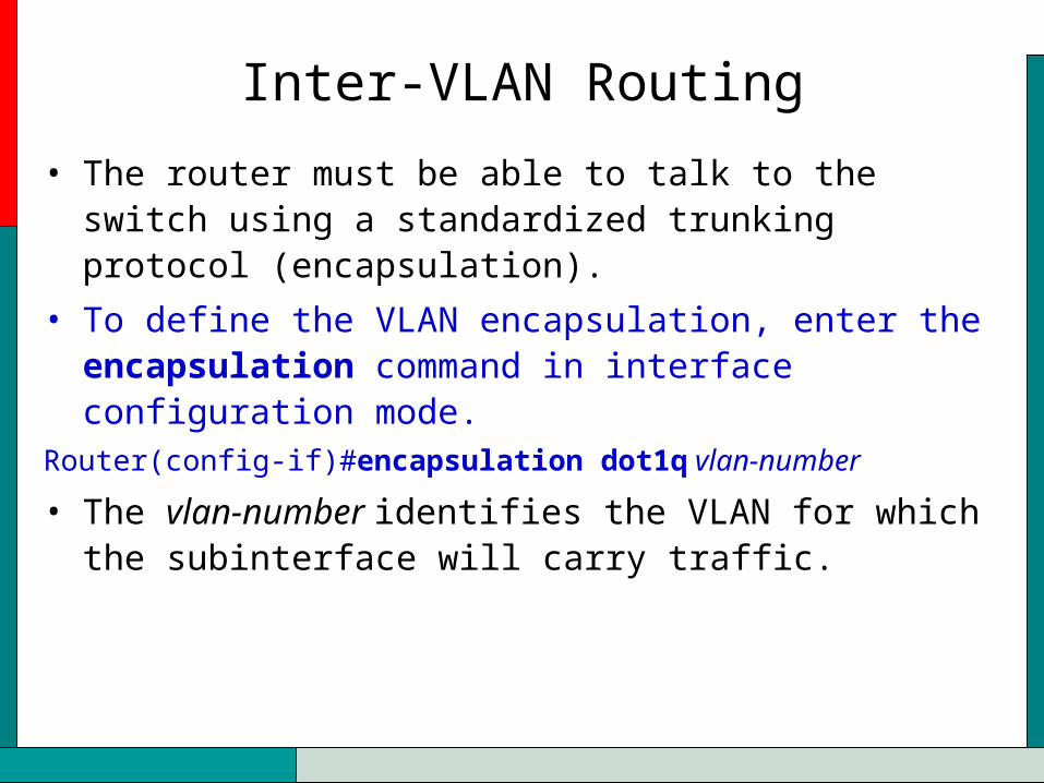
• The router must be able to talk to the switch using a standardized trunking protocol (encapsulation).
• To define the VLAN encapsulation, enter the encapsulation command in interface configuration mode.
Router(config-if)#encapsulation dot1q vlan-number
• The vlan-number identifies the VLAN for which the subinterface will carry traffic.

Inter-VLAN Routing
• To assign the IP address to the subinterface, enter the following command in subinterface configuration mode.
Router_A(config-subif)# ip address ip-address subnet-mask
Router_A(config)#interface fastethernet 0/0
Router_A(config-if)#no shutdown
Router_A(config-if)#interface fastethernet 0/0.1
Router_A(config-subif)#encapsulation dot1q 1
Router_A(config-subif)#ip address 192.168.1.1 255.255.255.0