david kring april 8, 2014 - unols kring april 8, 2014 ... transom stern modeling ... nonlinear free...
TRANSCRIPT
David Kring April 8, 2014
Green Boats: Ship Design Tools
Green Ports: Alternative Energy

Overview
Green Boats:
• Analysis and Design Methods
• Hydrodynamic Research
• Case Study: Wind Farm Vessel
Green Ports:
• Plasma actuation for Wind Turbines
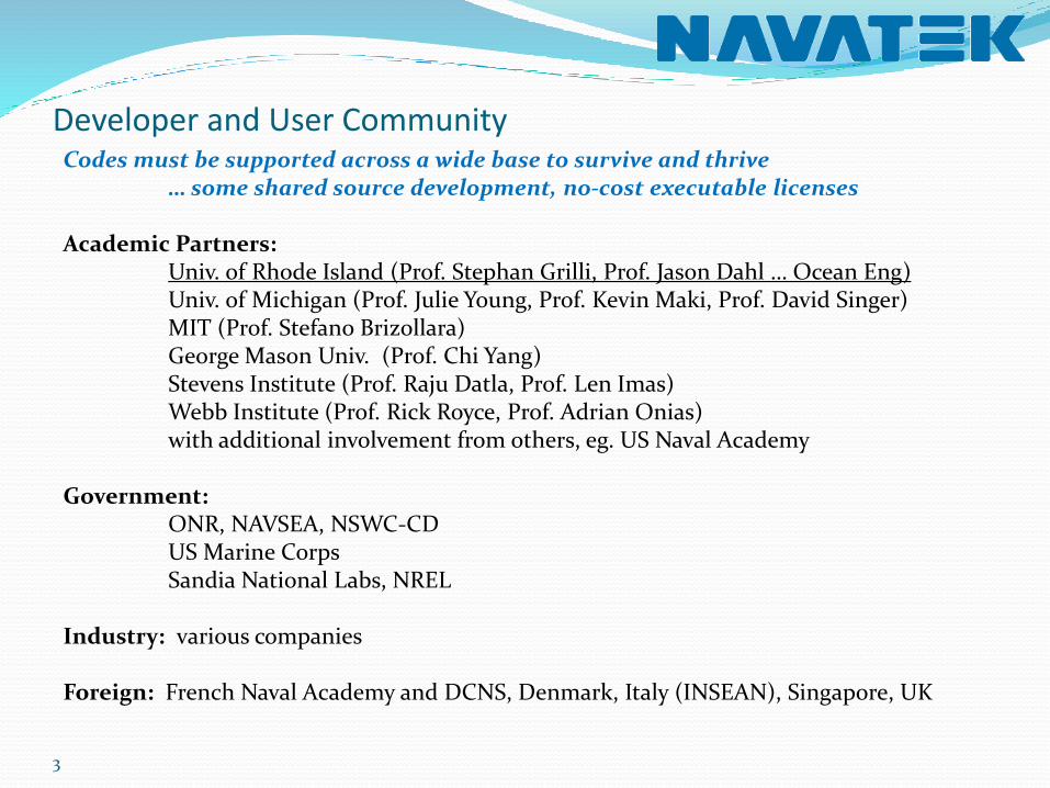
Developer and User Community
3
Codes must be supported across a wide base to survive and thrive… some shared source development, no-cost executable licenses
Academic Partners:Univ. of Rhode Island (Prof. Stephan Grilli, Prof. Jason Dahl … Ocean Eng)Univ. of Michigan (Prof. Julie Young, Prof. Kevin Maki, Prof. David Singer)MIT (Prof. Stefano Brizollara)George Mason Univ. (Prof. Chi Yang)Stevens Institute (Prof. Raju Datla, Prof. Len Imas)Webb Institute (Prof. Rick Royce, Prof. Adrian Onias)with additional involvement from others, eg. US Naval Academy
Government:ONR, NAVSEA, NSWC-CDUS Marine CorpsSandia National Labs, NREL
Industry: various companies
Foreign: French Naval Academy and DCNS, Denmark, Italy (INSEAN), Singapore, UK
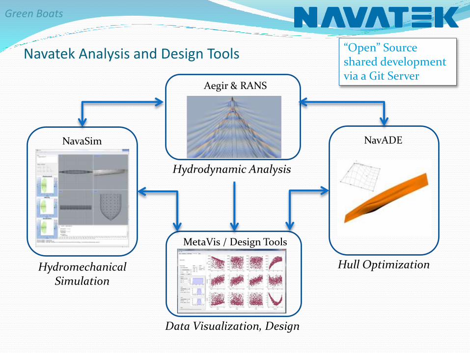
Navatek Analysis and Design Tools
MetaVis / Design Tools
Aegir & RANS
NavaSim NavADE
Hydrodynamic Analysis
Data Visualization, Design
HydromechanicalSimulation
Hull Optimization
“Open” Sourceshared development via a Git Server

Courtesy of Dr. Josh Knight, Prof. Dave Singer U.Mich
Design Methods: Escaping the Design Spiral
Set-based Designflexibility in the design process
Network Theoryidentifying important couplings
Markov Decision Processramifications of design decisions
Prospect-Theory Based Real Option Analogyhedging the design
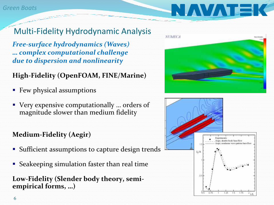
Multi-Fidelity Hydrodynamic Analysis
6
Free-surface hydrodynamics (Waves)… complex computational challengedue to dispersion and nonlinearity
High-Fidelity (OpenFOAM, FINE/Marine)
Few physical assumptions
Very expensive computationally … orders of magnitude slower than medium fidelity
Medium-Fidelity (Aegir)
Sufficient assumptions to capture design trends
Seakeeping simulation faster than real time
Low-Fidelity (Slender body theory, semi-empirical forms, …)
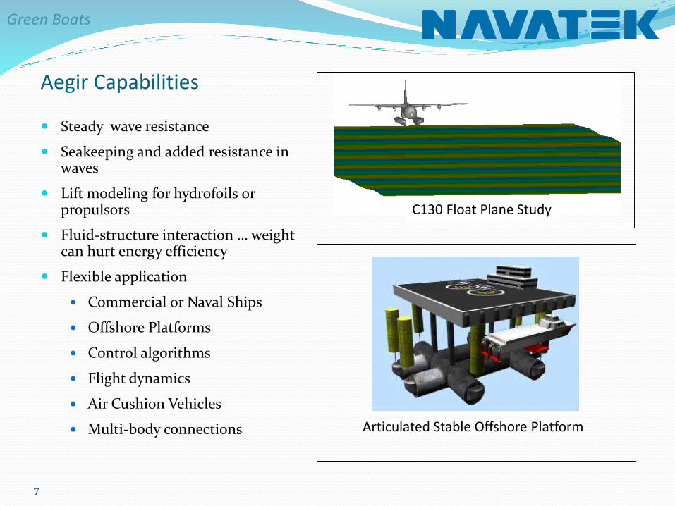
Steady wave resistance
Seakeeping and added resistance in waves
Lift modeling for hydrofoils or propulsors
Fluid-structure interaction … weight can hurt energy efficiency
Flexible application
Commercial or Naval Ships
Offshore Platforms
Control algorithms
Flight dynamics
Air Cushion Vehicles
Multi-body connections
C130 Float Plane Study
Articulated Stable Offshore Platform
7
Aegir Capabilities

8
Multi-hull Wave Resistance Validation

Hydrodynamics Research
Transom Stern Modeling
Verification and Validation
Efficient Hybrid Methods
Nonlinear Free Surface
3D High-Speed Simulations
STEM Ship Design Competition
Wave Loads & Structures
Impulse Response Functions
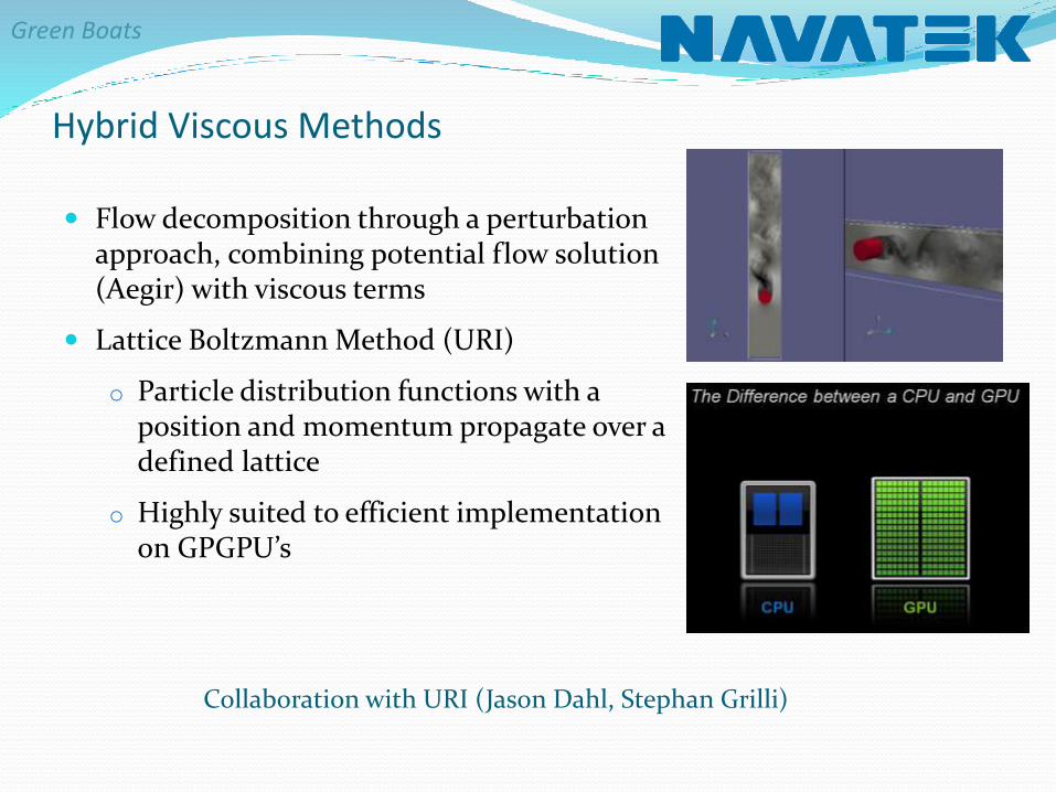
Flow decomposition through a perturbation approach, combining potential flow solution (Aegir) with viscous terms
Lattice Boltzmann Method (URI)
o Particle distribution functions with a position and momentum propagate over a defined lattice
o Highly suited to efficient implementation on GPGPU’s
Hybrid Viscous Methods
Collaboration with URI (Jason Dahl, Stephan Grilli)
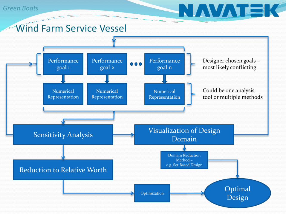
Performance goal n
Sensitivity Analysis
Reduction to Relative Worth
Visualization of Design Domain
Numerical Representation
Numerical Representation
Numerical Representation
Could be one analysis tool or multiple methods
Performance goal 2
Performance goal 1
Designer chosen goals –most likely conflicting
Optimal Design
Optimization
Domain Reduction Method –
e.g. Set Based Design
Wind Farm Service Vessel
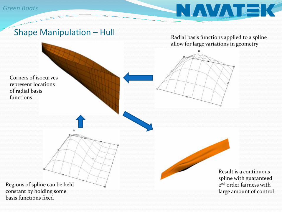
Shape Manipulation – Hull Radial basis functions applied to a spline allow for large variations in geometry
Regions of spline can be held constant by holding some basis functions fixed
Result is a continuous spline with guaranteed 2nd order fairness with large amount of control
Corners of isocurvesrepresent locations of radial basis functions

Shape Manipulation – Lifting Bodies
Radial basis functions not well suited for lifting surfaces in non-viscous solution – amount of freedom too great
Direct manipulation of gross dimensions used – span, chord, camber, thickness, angle, & position
chordspan
thicknesstop & bottom
angle
vertical & horizontal location

Evaluation of Candidate Designs
Aegir Steady Solution Stratford Criterion
Aegir Unsteady Solution Other Checks
X
Y
Z
Y
Z
X
• Wetted Area
• Sinkage
• Trim
• Wave Making Resistance
• Total Lift
• Dynamic Lift
• Total Moment
-60
-40
-20
0
20
40
60
-60
-40
-20
0
20
40
60
-60
-40
-20
0
20
40
60
0 0.1 0.2 0.3 0.4 0.5 0.6 0.7 0.8 0.9 1 𝐶𝑃 𝑥𝑑𝐶𝑝𝑑𝑥
=𝑅𝑒
106
0.1
𝑆
𝑆 =0.35
𝑑2𝑦
𝑑𝑥2> 0
0.39𝑑2𝑦
𝑑𝑥2< 0
Flat Spectrum Solution
Motions in flat spectrum can be used to estimate response in various conditions
60 70 80 90 100 110 120-2.5
-2
-1.5
-1
-0.5
0
0.5
1
1.5
2
2.5
X
Y
Z
Cavitation? – pressure < Pcav
Frictional resistance – ITTC ‘78
Separation likelihood

Determination of Relative Worth
𝐶 =𝐿
𝐷−
𝑈=0,17
𝜉3 + 𝜉5 ∗ 𝐶𝐴𝑉 ∗ 𝑆𝐸𝑃
𝐶𝐴𝑉 = 1 𝐻𝑢𝑙𝑙 𝑖𝑠 𝑛𝑜𝑡 𝑐𝑎𝑣𝑖𝑡𝑎𝑡𝑖𝑛𝑔0 𝐻𝑢𝑙𝑙 𝑖𝑠 𝑐𝑎𝑣𝑖𝑡𝑎𝑡𝑖𝑛𝑔
𝑆𝐸𝑃 = 1 𝐻𝑢𝑙𝑙 𝑖𝑠 𝑛𝑜𝑡 𝑠𝑒𝑝𝑎𝑟𝑎𝑡𝑖𝑛𝑔0 𝐻𝑢𝑙𝑙 𝑖𝑠 𝑠𝑒𝑝𝑎𝑟𝑎𝑡𝑖𝑛𝑔
Objective Function Particle Swarm Optimization
Desig
n p
ara
mete
r 2
Design parameter 1
Desig
n p
ara
mete
r 2
Design parameter 1
Global
optimum
Initial particle distribution in 2D
design space
Particle distribution after
optimization
Heave motions at CG Pitch motions at CG
𝑣𝑖 𝑡 + 1 = 𝑤𝑣𝑖 𝑡 + 𝐶𝑙 𝑙𝑖 − 𝑥𝑖 𝑡 + 𝐶𝑔 𝑔[𝑡] − 𝑥𝑖 𝑡
𝑥𝑖 𝑡 + 1 = 𝑥𝑖 𝑡 + 𝑣𝑖 𝑡 + 1
Optimal Design
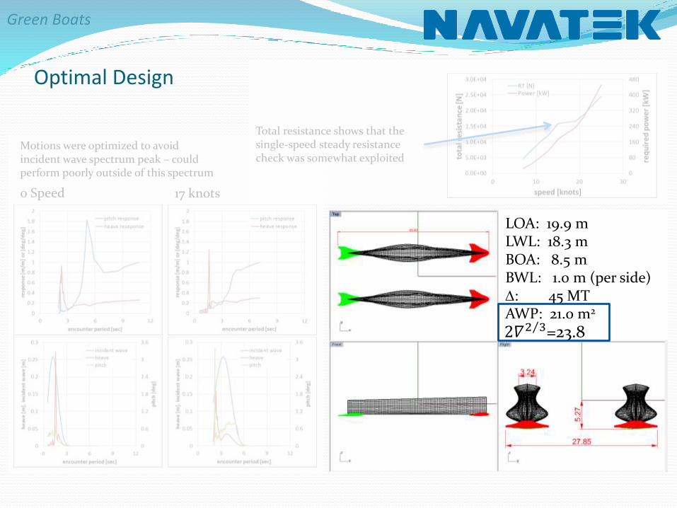
LOA: 19.9 mLWL: 18.3 mBOA: 8.5 mBWL: 1.0 m (per side)D: 45 MTAWP: 21.0 m2
2𝛻 2 3=23.8
0 Speed 17 knots
Motions were optimized to avoid incident wave spectrum peak – could perform poorly outside of this spectrum
Total resistance shows that the single-speed steady resistance check was somewhat exploited
Optimal Design
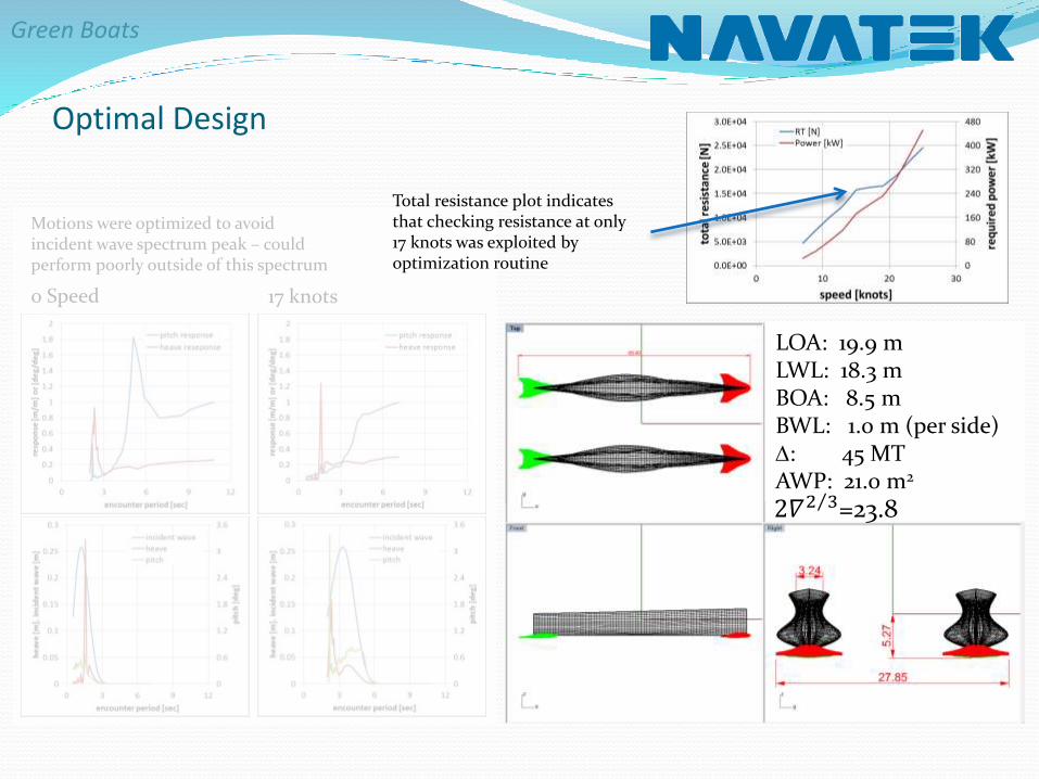
LOA: 19.9 mLWL: 18.3 mBOA: 8.5 mBWL: 1.0 m (per side)D: 45 MTAWP: 21.0 m2
2𝛻 2 3=23.8
0 Speed 17 knots
Motions were optimized to avoid incident wave spectrum peak – could perform poorly outside of this spectrum
Total resistance plot indicates that checking resistance at only 17 knots was exploited by optimization routine

Total resistance plot indicates that checking resistance at only 17 knots was exploited by optimization routine
Optimal Design
LOA: 19.9 mLWL: 18.3 mBOA: 8.5 mBWL: 1.0 m (per side)D: 45 MTAWP: 21.0 m2
2𝛻 2 3=23.8
0 Speed 17 knots
Motions were optimized to avoid incident wave spectrum peak – could perform poorly outside of this spectrum