date: 8/8/2002 design animation - ptc.com: log...
TRANSCRIPT

Title: Design Animation Date: 8/8/2002 PTC-MSS Services
Design Animation
Table of Contents:
1) Overview 2) Tutorial 3) Key Vocabulary 4) Tutorial Evaluation
Page 1 of 20
Title: Design Animation Date: 8/8/2002 PTC-MSS Services
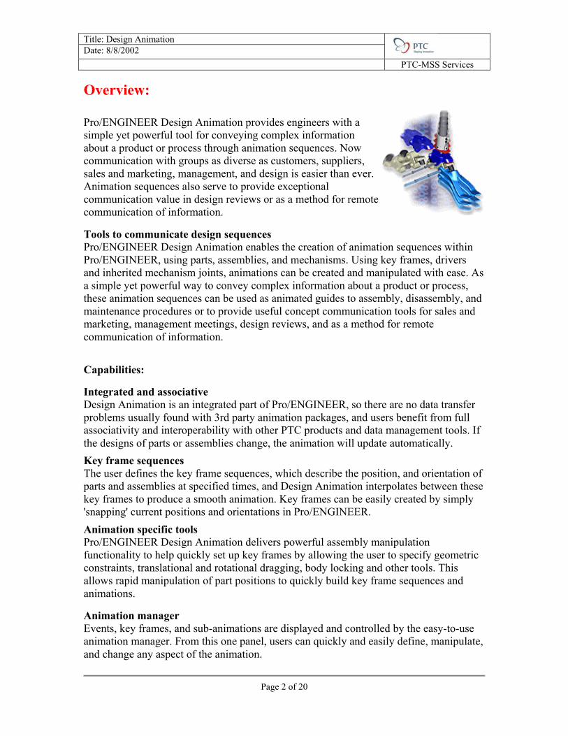
Overview: Pro/ENGINEER Design Animation provides engineers with a simple yet powerful tool for conveying complex information about a product or process through animation sequences. Now communication with groups as diverse as customers, suppliers, sales and marketing, management, and design is easier than ever. Animation sequences also serve to provide exceptional communication value in design reviews or as a method for remote communication of information.
Tools to communicate design sequences Pro/ENGINEER Design Animation enables the creation of animation sequences within Pro/ENGINEER, using parts, assemblies, and mechanisms. Using key frames, drivers and inherited mechanism joints, animations can be created and manipulated with ease. As a simple yet powerful way to convey complex information about a product or process, these animation sequences can be used as animated guides to assembly, disassembly, and maintenance procedures or to provide useful concept communication tools for sales and marketing, management meetings, design reviews, and as a method for remote communication of information.
Capabilities:
Integrated and associative Design Animation is an integrated part of Pro/ENGINEER, so there are no data transfer problems usually found with 3rd party animation packages, and users benefit from full associativity and interoperability with other PTC products and data management tools. If the designs of parts or assemblies change, the animation will update automatically. Key frame sequences The user defines the key frame sequences, which describe the position, and orientation of parts and assemblies at specified times, and Design Animation interpolates between these key frames to produce a smooth animation. Key frames can be easily created by simply 'snapping' current positions and orientations in Pro/ENGINEER. Animation specific tools Pro/ENGINEER Design Animation delivers powerful assembly manipulation functionality to help quickly set up key frames by allowing the user to specify geometric constraints, translational and rotational dragging, body locking and other tools. This allows rapid manipulation of part positions to quickly build key frame sequences and animations.
Animation manager Events, key frames, and sub-animations are displayed and controlled by the easy-to-use animation manager. From this one panel, users can quickly and easily define, manipulate, and change any aspect of the animation.
Page 2 of 20

Title: Design Animation Date: 8/8/2002 PTC-MSS Services Design intent re-use The mechanism joints used to create and move assemblies in Pro/ENGINEER Mechanism Design are re-used by Pro/ENGINEER Design Animation where they can be selectively activated and de-activated at any stage during animation sequences.
Page 3 of 20
Title: Design Animation Date: 8/8/2002 PTC-MSS Services
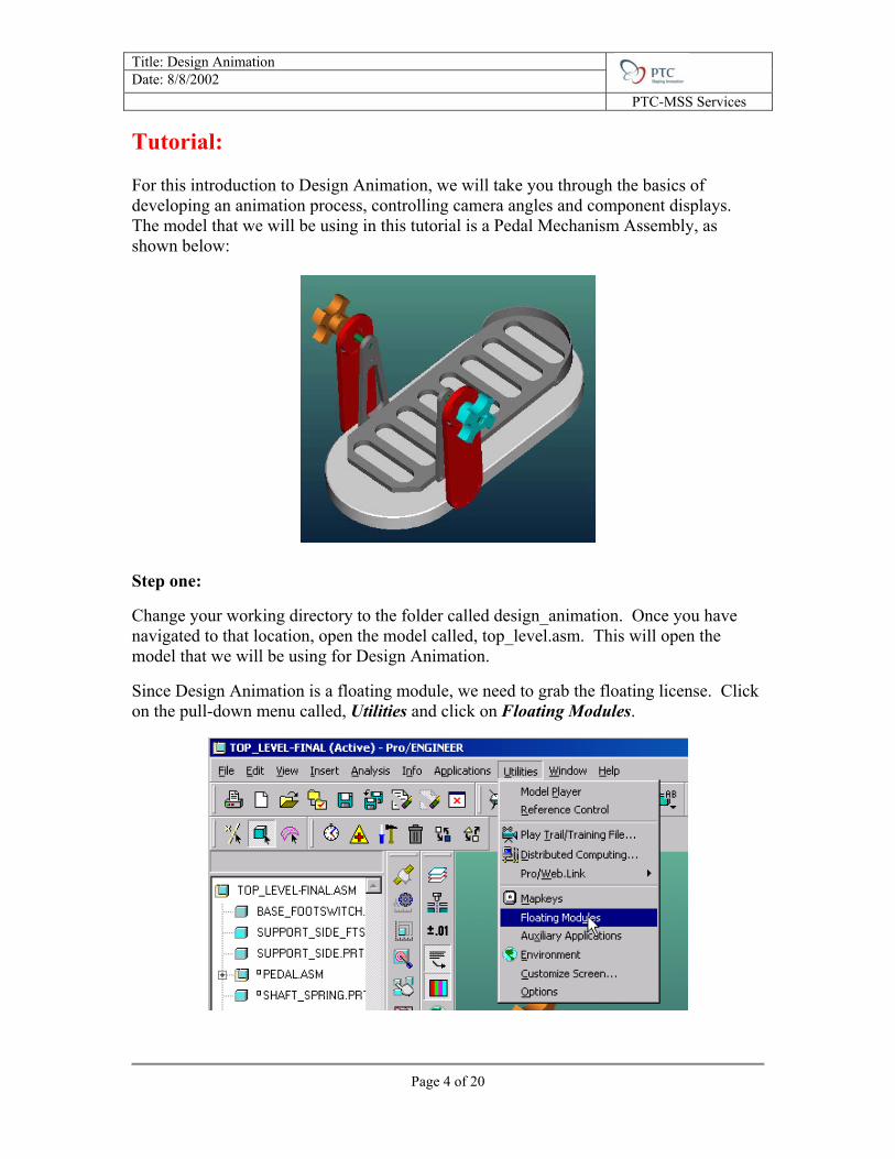
Tutorial: For this introduction to Design Animation, we will take you through the basics of developing an animation process, controlling camera angles and component displays. The model that we will be using in this tutorial is a Pedal Mechanism Assembly, as shown below:
Step one:
Change your working directory to the folder called design_animation. Once you have navigated to that location, open the model called, top_level.asm. This will open the model that we will be using for Design Animation.
Since Design Animation is a floating module, we need to grab the floating license. Click on the pull-down menu called, Utilities and click on Floating Modules.
Page 4 of 20
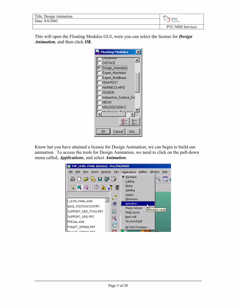
Title: Design Animation Date: 8/8/2002 PTC-MSS Services This will open the Floating Modules GUI, were you can select the license for Design Animation, and then click OK.
Know hat you have attained a license for Design Animation; we can begin to build our animation. To access the tools for Design Animation, we need to click on the pull-down menu called, Applications, and select Animation.
Page 5 of 20

Title: Design Animation Date: 8/8/2002 PTC-MSS Services This will open the new Design Animation toolbars: And open the Sequencer Window:
Animation
Animation Icon Display
Body Definition in Animation
Drag Model and Create Snapshots
Create New Keyframe Sequence
Create New Body – Body Lock
Create New Driver
Create New View @ Time
Create New Display @ Time
Edit Selected Animation Object
Undo
Redo
Remove Selected Entity
Start Animation
Playback
Export the Animation
Sequencer Window
Page 6 of 20
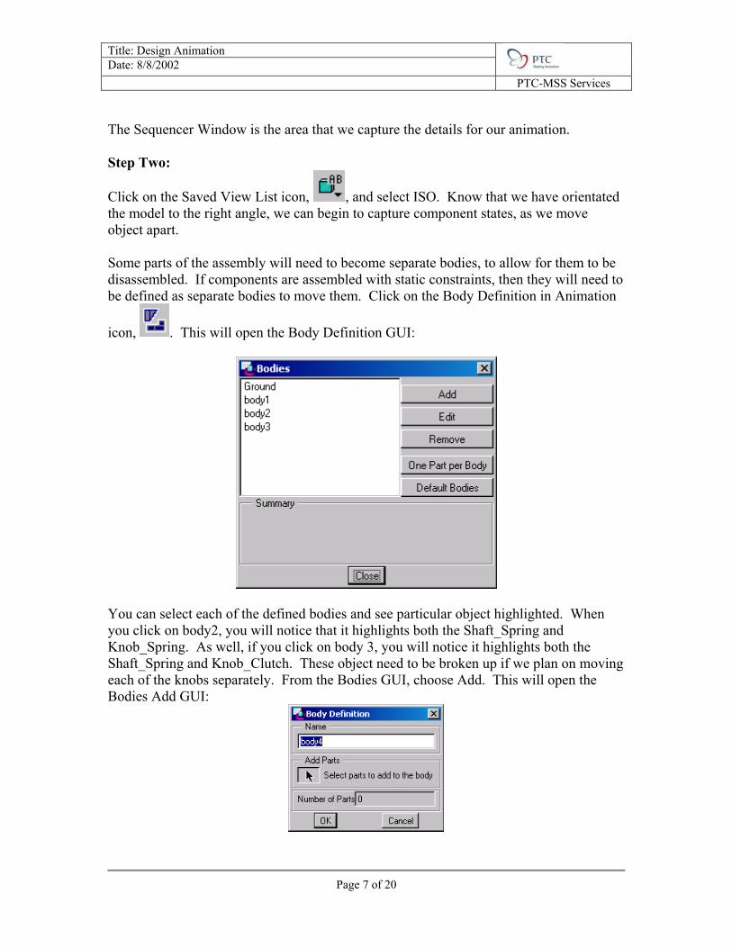
Title: Design Animation Date: 8/8/2002 PTC-MSS Services The Sequencer Window is the area that we capture the details for our animation. Step Two:
Click on the Saved View List icon, , and select ISO. Know that we have orientated the model to the right angle, we can begin to capture component states, as we move object apart. Some parts of the assembly will need to become separate bodies, to allow for them to be disassembled. If components are assembled with static constraints, then they will need to be defined as separate bodies to move them. Click on the Body Definition in Animation
icon, . This will open the Body Definition GUI:
You can select each of the defined bodies and see particular object highlighted. When you click on body2, you will notice that it highlights both the Shaft_Spring and Knob_Spring. As well, if you click on body 3, you will notice it highlights both the Shaft_Spring and Knob_Clutch. These object need to be broken up if we plan on moving each of the knobs separately. From the Bodies GUI, choose Add. This will open the Bodies Add GUI:
Page 7 of 20
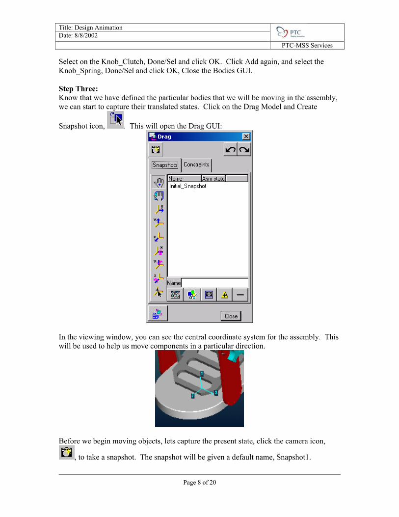
Title: Design Animation Date: 8/8/2002 PTC-MSS Services Select on the Knob_Clutch, Done/Sel and click OK. Click Add again, and select the Knob_Spring, Done/Sel and click OK, Close the Bodies GUI. Step Three: Know that we have defined the particular bodies that we will be moving in the assembly, we can start to capture their translated states. Click on the Drag Model and Create
Snapshot icon, . This will open the Drag GUI:
In the viewing window, you can see the central coordinate system for the assembly. This will be used to help us move components in a particular direction.
Before we begin moving objects, lets capture the present state, click the camera icon,
, to take a snapshot. The snapshot will be given a default name, Snapshot1.
Page 8 of 20
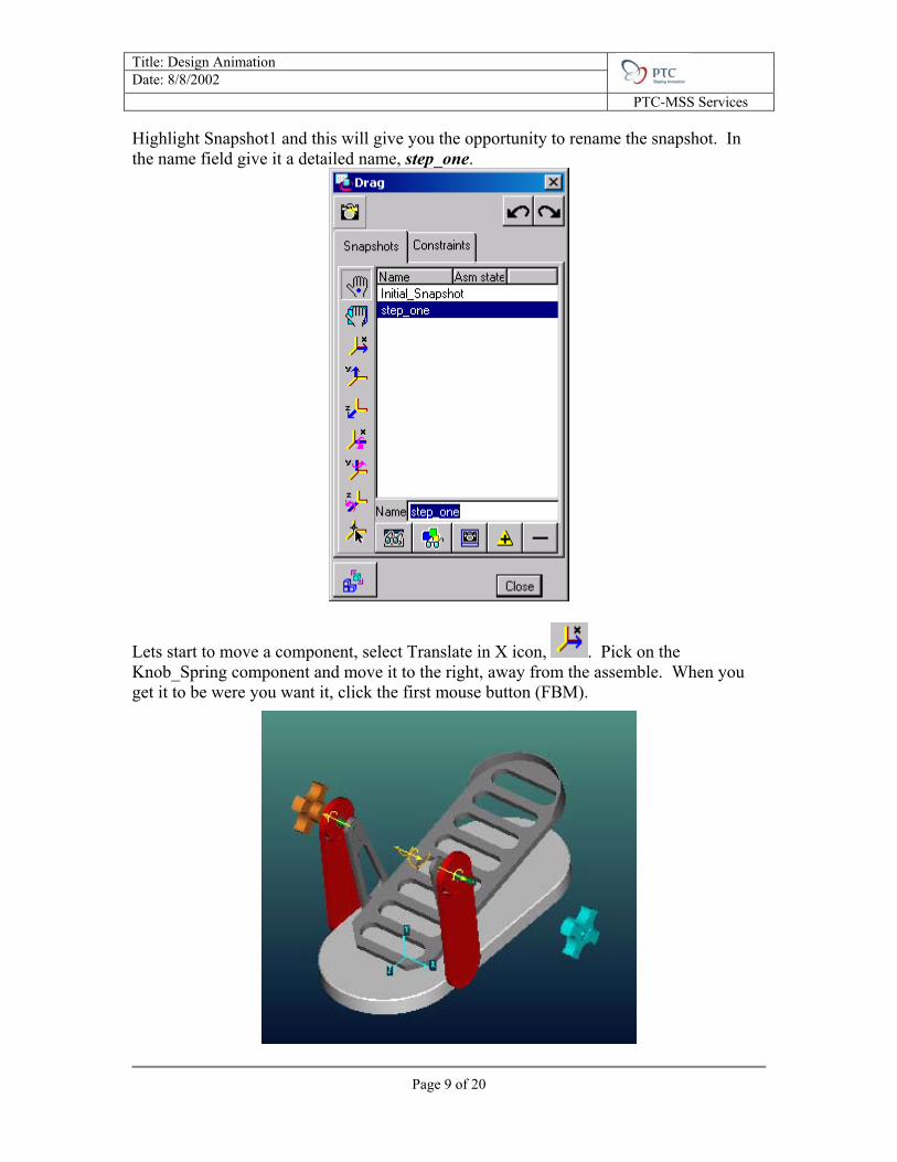
Title: Design Animation Date: 8/8/2002 PTC-MSS Services Highlight Snapshot1 and this will give you the opportunity to rename the snapshot. In the name field give it a detailed name, step_one.
Lets start to move a component, select Translate in X icon, . Pick on the Knob_Spring component and move it to the right, away from the assemble. When you get it to be were you want it, click the first mouse button (FBM).
Page 9 of 20

Title: Design Animation Date: 8/8/2002 PTC-MSS Services
Click the camera icon, , to take a new snapshot. The snapshot will be given a default name, Snapshot2. Highlight Snapshot2 and this will give you the opportunity to rename the snapshot. In the name field give it a detailed name, step_two.
Repeat this process for the Knob_Clutch. Select Translate in X icon, , click the component and move it to the left, away from the assembly. Click the FMB to place the
component were you like it. Click the camera icon, , to take a new snapshot. The snapshot will be given a default name, Snapshot. Highlight Snapshot3 and this will give you the opportunity to rename the snapshot. In the name field give it a detailed name, step_three.
Mechanism Constraint
Step Four: Know that we have translated the knobs. We can start to move the other components. In the assembly, we see mechanism constraint symbols on the components we want to move. Since they were assembled with these special types of constraints (see Mechanism Tutorial to learn more about mechanism constraints), we need to disable them to translate the component. Still in the Drag GUI, select the Constraint tab. This will open new options to select from.
Page 10 of 20

Title: Design Animation Date: 8/8/2002 PTC-MSS Services
We can perform a variety of tasks from this window, however we are concerned with
disabling the existing constraints. Select the Enable/Disable Constraint icon, . This will allow you to select a constraint, select the following pin-joint:
Once you have highlighted it red, click done/Sel, this disable the constraint and show it in the list.
Page 11 of 20

Title: Design Animation Date: 8/8/2002 PTC-MSS Services
Select the Snapshots tab again and select the Translate in X icon, . Pick the Shaft_Spring component were we disabled the constraint and move it to the right away
from the assembly. Click the camera icon, , to take a new snapshot. The snapshot will be given a default name, Snapshot4. Highlight Snapshot4 and this will give you the opportunity to rename the snapshot. In the name field give it a detailed name, step_four.
Page 12 of 20

Title: Design Animation Date: 8/8/2002 PTC-MSS Services Lets move the other knob. Still in the Drag GUI, select the Constraint tab. This will open new options to select from.
Select the Enable/Disable Constraint icon, . This will allow you to select a constraint, select the following pin-joint:
Once you have highlighted it red, click done/Sel, this disable the constraint and show it in the list.
Page 13 of 20
Title: Design Animation Date: 8/8/2002 PTC-MSS Services
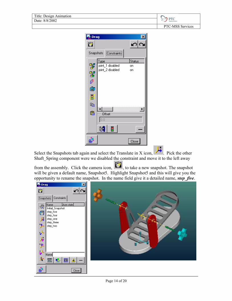
Select the Snapshots tab again and select the Translate in X icon, . Pick the other Shaft_Spring component were we disabled the constraint and move it to the left away
from the assembly. Click the camera icon, , to take a new snapshot. The snapshot will be given a default name, Snapshot5. Highlight Snapshot5 and this will give you the opportunity to rename the snapshot. In the name field give it a detailed name, step_five.
Page 14 of 20

Title: Design Animation Date: 8/8/2002 PTC-MSS Services Only one more component to move, the pedal. We will need to disable one last constraint. Still in the Drag GUI, select the Constraint tab. This will open new options to
select from. Select the Enable/Disable Constraint icon, . This will allow you to select a constraint, select the following pin-joint:
Once you have highlighted it red, click done/Sel, this disable the constraint and show it in the list.
Select the Snapshots tab again and select the Translate in X icon, . Pick the other Pedal component were we disabled the constraint and move it up away from the
assembly. Click the camera icon, , to take a new snapshot. The snapshot will be given a default name, Snapshot6. Highlight Snapshot6 and this will give you the opportunity to rename the snapshot. In the name field give it a detailed name, step_six.
Page 15 of 20
Title: Design Animation Date: 8/8/2002 PTC-MSS Services
Page 16 of 20
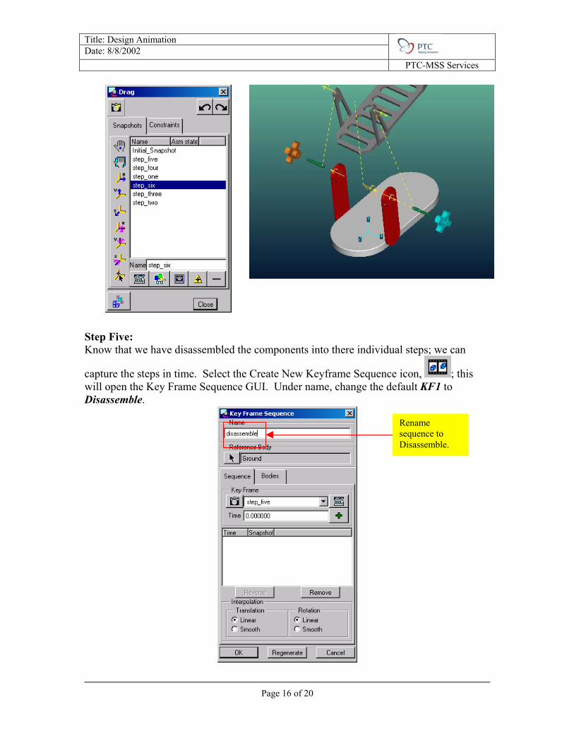
Step Five: Know that we have disassembled the components into there individual steps; we can
capture the steps in time. Select the Create New Keyframe Sequence icon, ; this will open the Key Frame Sequence GUI. Under name, change the default KF1 to Disassemble.
Rename sequence to Disassemble.

Title: Design Animation Date: 8/8/2002 PTC-MSS Services Under Key Frame, click he pull down menu and select step_six, with a time of zero.
Click the Add Keyframe icon, ; this will add the Keyframe to the list, as well as, the sequence window.
Next click the Keyframe pull down menu again and select step_five. This time we are going to edit the time. By default the time will have changed to 1 sec., we are going to
put 2 sec. Once you have made the changes click the Add Keyframe icon, . Repeat the previous steps to add the keyframes until you have added all the steps. When you are done it should look like the following, every step will be 2 seconds apart. Click OK to exit the GUI.
Page 17 of 20

Title: Design Animation Date: 8/8/2002 PTC-MSS Services Step Six: Know that we have defined the Keyframe in the sequence window; lets play the sequence
to see what it looks like, click the Start the Animation icon, . How does that look? Lets add another level of detail, by capturing camera angles at specific times. Click the
Create a New View @ Time icon, ; this will open View @ Time GUI.
Under the Name pull down menu select the predefined view called Right, click Apply, this will add the view to the sequence window.
Click the Name pull down menu and select ISO. Under the Time area put 3 in the value field, click Apply. Repeat adding the following views; Angle and ISO2, at 3-second intervals. When you are done it should look something like this:
Play the sequence; click the Start the Animation icon, . If the camera angles are not were you want them, you can click on the camera object in the sequence window and move it to were you want it.
Page 18 of 20

Title: Design Animation Date: 8/8/2002 PTC-MSS Services Step Seven:
Lets view the animation, click the Playback icon, . This will open the Playback GUI; it looks like a VCR control panel.
Click the icon to play the animation; you can even control the speed by moving the toggle switch. If you want to save the animation to a movie file (MPEG), click capture.
Leaving everything as default, click ok, this start to create the movie. Save the file in Pro/E. You are done the tutorial! There are other details you can add to the animation, like Display settings and render output. If this is of interest, please contact you local Design Animation export. Open the file called Final_Top_Level.asm to see the advance details.
Page 19 of 20
Title: Design Animation Date: 8/8/2002 PTC-MSS Services
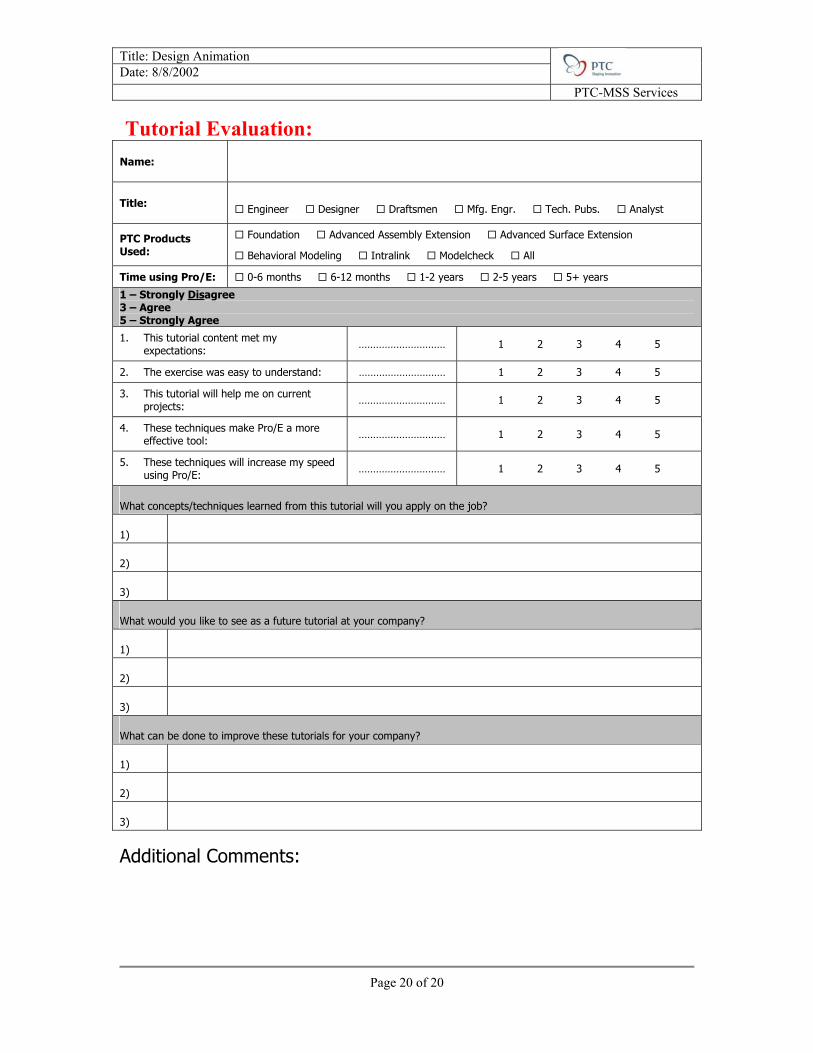
Tutorial Evaluation:
Name:
Title: Engineer Designer Draftsmen Mfg. Engr. Tech. Pubs. Analyst
PTC Products Used:
Foundation Advanced Assembly Extension Advanced Surface Extension
Behavioral Modeling Intralink Modelcheck All
Time using Pro/E: 0-6 months 6-12 months 1-2 years 2-5 years 5+ years
1 – Strongly Disagree 3 – Agree 5 – Strongly Agree
1. This tutorial content met my expectations: ………………………… 1 2 3 4 5
2. The exercise was easy to understand: ………………………… 1 2 3 4 5
3. This tutorial will help me on current projects: ………………………… 1 2 3 4 5
4. These techniques make Pro/E a more effective tool: ………………………… 1 2 3 4 5
5. These techniques will increase my speed using Pro/E: ………………………… 1 2 3 4 5
What concepts/techniques learned from this tutorial will you apply on the job?
1)
2)
3)
What would you like to see as a future tutorial at your company?
1)
2)
3)
What can be done to improve these tutorials for your company?
1)
2)
3)
Additional Comments:
Page 20 of 20