data communications (under graduate course) lecture 4 of 5
TRANSCRIPT
Dr. Randa Elanwar
2012-2013
Introduction:
So far, we have discussed base band digital systems where signals are transmitted directly without any shift in the frequencies of the signal.
Because baseband signals have sizable power at low frequencies, they are suitable for transmission over a pair of wires, coaxial cables or optical fibers (guided-limited distance channels).
Data Communications Dr. Randa Elanwar 2012-2013 2

Introduction: Baseband signals cannot be transmitted over a
radio link or satellite because in such case we need large antenna to radiate low frequency spectrum of signal.
Effective radiation of EM waves requires antenna dimensions comparable with the wavelength:
Antenna for 3 kHz would be ~100 km long Antenna for 3 GHz carrier is 10 cm long
Therefore, the signal spectrum has to be shifted to a high frequency range.
Data Communications Dr. Randa Elanwar 2012-2013 3
Introduction:
Shifting signal spectrum to a higher frequency range has another advantage which is that we can transmit several messages simultaneously by sharing the large bandwidth of the transmission medium.
The spectrum of a signal can be shifted to a higher frequency by modulating a high frequency analog carrier signal by the baseband signal. Sinusoidal waves, pulse train, square wave, etc. can be used as carriers.
Data Communications Dr. Randa Elanwar 2012-2013 4

Introduction:
A modem (modulator-demodulator) is a device that modulates an analog carrier signal to encode digital information, and also demodulates such a carrier signal to decode the transmitted information.
In other words, modulators embed information into waveform with frequencies passed by bandpass channel
Data Communications Dr. Randa Elanwar 2012-2013 5
Band pass channels:
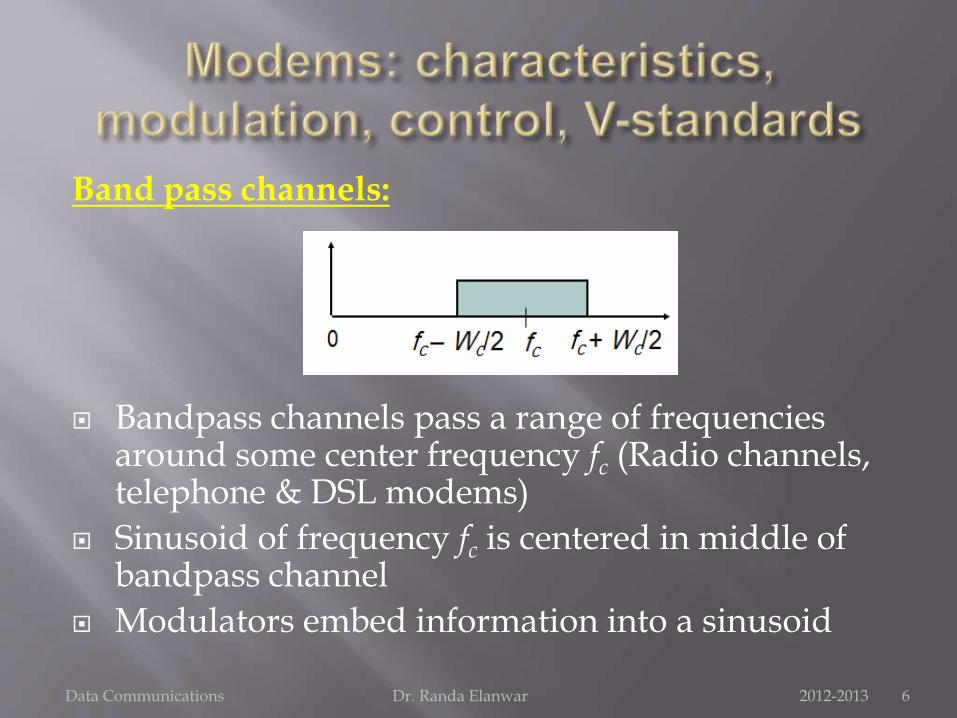
Bandpass channels pass a range of frequencies around some center frequency fc (Radio channels, telephone & DSL modems)
Sinusoid of frequency fc is centered in middle of bandpass channel
Modulators embed information into a sinusoid
Data Communications Dr. Randa Elanwar 2012-2013 6

fc take different values according to communication channel type:
Data Communications Dr. Randa Elanwar 2012-2013 7
What does this mean? This means “ANALOG TRANSMISSION OF DIGITAL DATA”!!!
Yes because: for long distance communications we get much less attenuation for analog carrier than digital.
Data Communications Dr. Randa Elanwar 2012-2013 8

Data Communications Dr. Randa Elanwar 2012-2013 9
Thus:
Modulation A process that converts the digital information sequences into waveforms that are compatible with the characteristics of the channel.
Why we need modulation? Reduce noise and interference.
Channel assignment, reusability.
Multiplexing (transmission of several messages from multiple transmitters over a single channel)
Overcome equipment limitation.
Data Communications Dr. Randa Elanwar 2012-2013 10
The carrier signal has three characteristics: amplitude, frequency and phase. Modulation is achieved by varying any of the three characteristics according to the transmitted modulating signal.
Thus, modulation exists in two forms: Amplitude modulation (AM) and Angle modulation (frequency modulation: FM, phase modulation: PM)
Data Communications Dr. Randa Elanwar 2012-2013 11

Data Communications Dr. Randa Elanwar 2012-2013 12
Data Communications Dr. Randa Elanwar 2012-2013 13
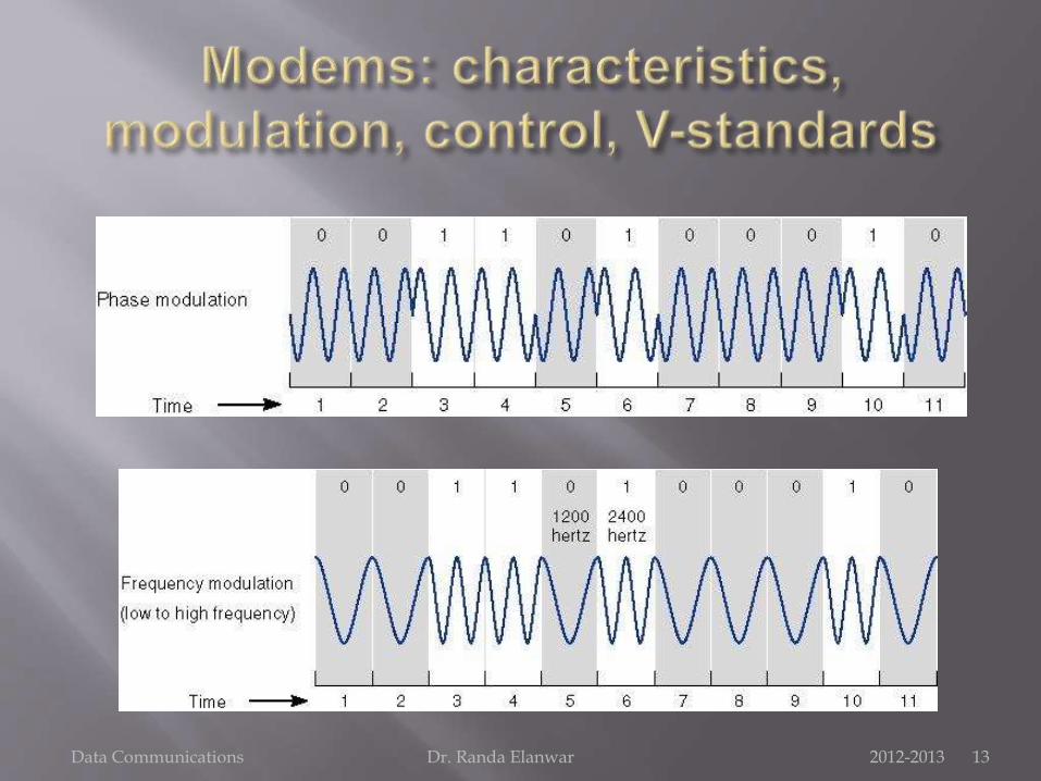
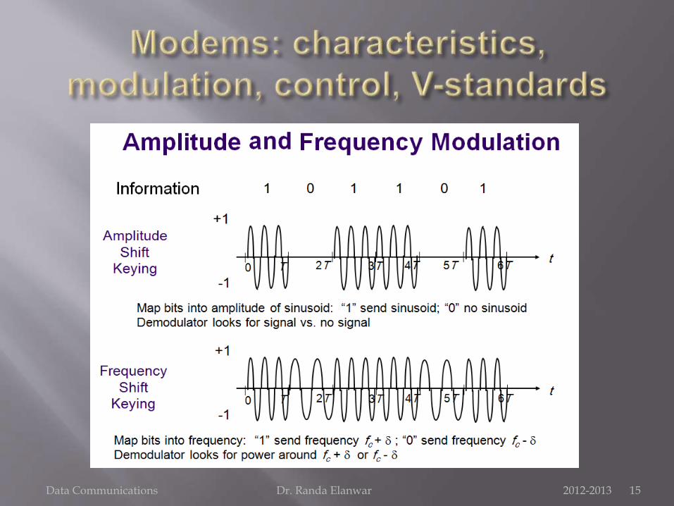
In amplitude modulation, the carrier amplitude is varied in proportion to the modulating signal (baseband signal). If the modulating signal is binary (OOK, polar, etc.) we call this Amplitude shift keying (ASK).
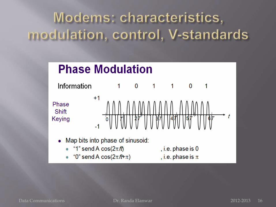
If the carrier phase is varied in proportion to the modulating signal (baseband signal) we call it Phase shift keying (PSK) and if the carrier frequency is varied in proportion to the modulating signal (baseband signal) we call it Frequency shift keying (FSK)
Data Communications Dr. Randa Elanwar 2012-2013 14
Data Communications Dr. Randa Elanwar 2012-2013 15
Data Communications Dr. Randa Elanwar 2012-2013 16

Sending Multiple Bits Simultaneously
Each of the three modulation techniques (ASK, FSK, PSK) can be refined to send more than one bit at a time. It is possible to send two bits on one wave by defining four different amplitudes (example: source extension case).
This technique could be further refined to send three bits at the same time by defining 8 different amplitude levels or four bits by defining 16, etc. The same approach can be used for frequency and phase modulation.
Data Communications Dr. Randa Elanwar 2012-2013 17
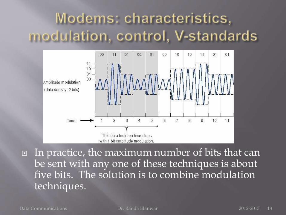
In practice, the maximum number of bits that can be sent with any one of these techniques is about five bits. The solution is to combine modulation techniques.
Data Communications Dr. Randa Elanwar 2012-2013 18
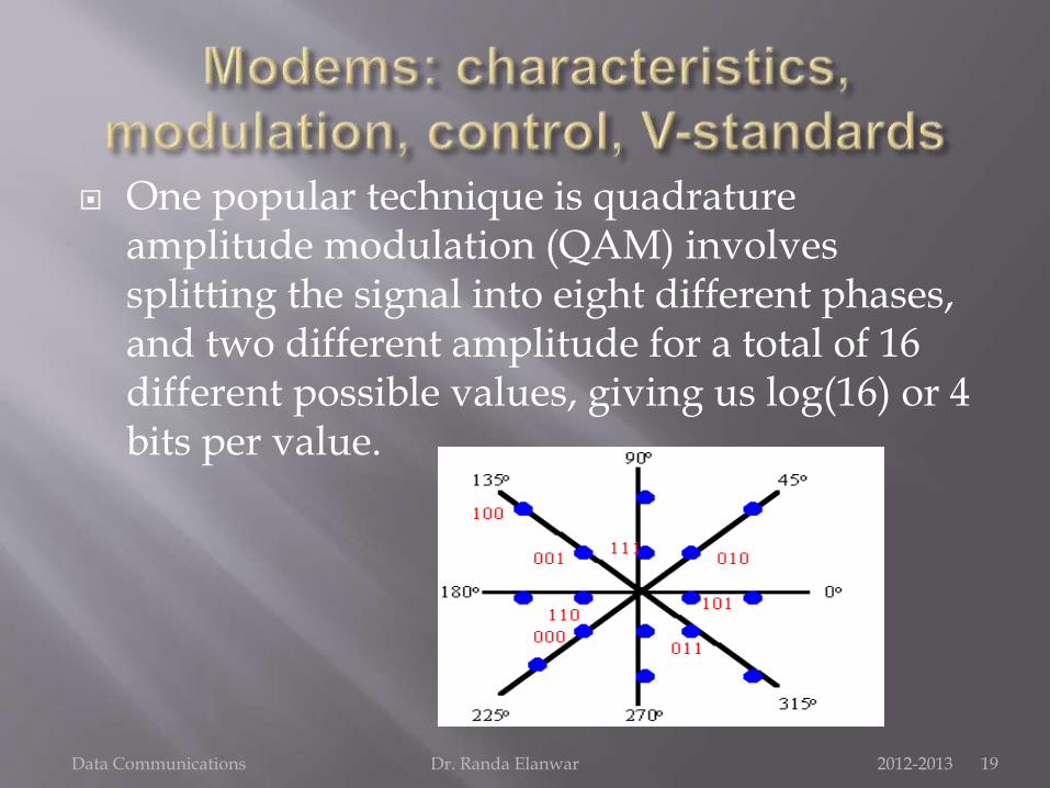
One popular technique is quadratureamplitude modulation (QAM) involves splitting the signal into eight different phases, and two different amplitude for a total of 16 different possible values, giving us log(16) or 4 bits per value.
Data Communications Dr. Randa Elanwar 2012-2013 19
Another popular high speed modulation technique is Trellis coded modulation (TCM) which is an enhancement of QAM that combines phase modulation and amplitude modulation but is more sensitive to imperfections in the communications circuit.
Before knowing the types of different modems, their characteristics and the criteria of choosing a modem, we first need to learn the following concepts:
Digital multiplexing
Multiple access control
Duplexing
Transmission modes and standards
Data Communications Dr. Randa Elanwar 2012-2013 20

Digital Multiplexing:
A multiplexer puts two or more simultaneous transmissions on a single communications circuit.
A multiplexer (or MUX) is a device that selects one of several analog or digital input signals and forwards the selected input into a single line.
A multiplexer makes it possible for several signals to share one communication line and save cost.
Data Communications Dr. Randa Elanwar 2012-2013 21

Digital Multiplexing:
A multiplexer of 2n inputs has n select lines, which are used to select which input line to send to the output.
Multiplexers are mainly used to increase the amount of data that can be sent over the network within a certain amount of time and bandwidth. A multiplexer is also called a data selector.
Data Communications Dr. Randa Elanwar 2012-2013 22

Digital Multiplexing:
Conversely, at the receiving end of the data link a complementary demultiplexer (or demux) is normally required to break single data stream back down into the original streams.
Generally, the multiplexed circuit must have the same capacity as the sum of the circuits it combines.
Data Communications Dr. Randa Elanwar 2012-2013 23

Digital Multiplexing: In telecommunications and signal processing, a digital
TDM multiplexer may combine a limited number of constant bit rate digital data streams into one data stream of a higher data rate, by forming data frames consisting of one timeslot per channel.
In telecommunications, computer networks and digital video, a statistical multiplexer may combine several variable bit rate data streams into one constant bandwidth signal, for example by means of packet mode communication. An inverse multiplexer may utilize several communication channels for transferring one signal.
Data Communications Dr. Randa Elanwar 2012-2013 24
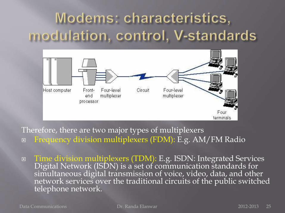
Therefore, there are two major types of multiplexers Frequency division multiplexers (FDM): E.g. AM/FM Radio
Time division multiplexers (TDM): E.g. ISDN: Integrated Services Digital Network (ISDN) is a set of communication standards for simultaneous digital transmission of voice, video, data, and other network services over the traditional circuits of the public switched telephone network.
Data Communications Dr. Randa Elanwar 2012-2013 25
Frequency Division Multiplexing (FDM):
Frequency division multiplexers can be described as dividing the circuit “horizontally” so that many signals can travel a single communication circuit simultaneously.
The circuit is divided into a series of separate channels, each transmitting on a different frequency.
Guardbands are employed to keep one channel from leaking over into another channel.
Data Communications Dr. Randa Elanwar 2012-2013 26
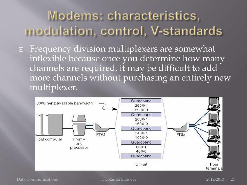
Frequency division multiplexers are somewhat inflexible because once you determine how many channels are required, it may be difficult to add more channels without purchasing an entirely new multiplexer.
Data Communications Dr. Randa Elanwar 2012-2013 27
Time Division Multiplexing (TDM):
Time division multiplexing shares a circuit among two or more terminals by having them take turns, dividing the circuit “vertically.”
Time on the circuit is allocated even when data are not transmitted, so that some capacity is wasted when a terminal is idle.
Data Communications Dr. Randa Elanwar 2012-2013 28
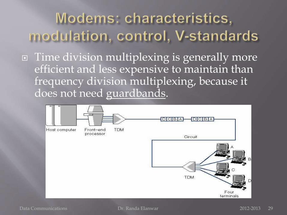
Time division multiplexing is generally more efficient and less expensive to maintain than frequency division multiplexing, because it does not need guardbands.
Data Communications Dr. Randa Elanwar 2012-2013 29

It became obvious that the block diagram of a typical communication system has more blocks than we discussed before:
Data Communications Dr. Randa Elanwar 2012-2013 30
We are concerned now with the modulator, multiplexer and multiple access blocks.

Multiple access control:
A channel-access scheme is based on a multiplexing method, that allows several data streams or signals to share the same communication channel.
A channel-access scheme is also based on a multiple access protocol and control mechanism, also known as media access control (MAC). This protocol deals with issues such as addressing, assigning multiplex channels to different users, and avoiding collisions.
Data Communications Dr. Randa Elanwar 2012-2013 31

These are the four fundamental types of channel access schemes:
1. The frequency division multiple access (FDMA) channel-access scheme is based on the frequency-division multiplex (FDM) scheme, which provides different frequency bands to different data-streams.
In FDMA, the data streams are allocated to different nodes or devices.
An example of FDMA systems were the first-generation (1G) cell-phone systems, where each phone call was assigned to a specific uplink frequency channel, and another downlink frequency channel. Each message signal (each phone call) is modulated on a specific carrier frequency.
Data Communications Dr. Randa Elanwar 2012-2013 32

2. The time division multiple access (TDMA) channel access scheme is based on the time division multiplex (TDM) scheme, which provides different time-slots to different data-streams (in the TDMA case to different transmitters) in a cyclically repetitive frame structure.
As an example, 2G cellular systems are based on a combination of TDMA and FDMA. Each frequency channel is divided into eight timeslots, of which seven are used for seven phone calls, and one for signaling data
Data Communications Dr. Randa Elanwar 2012-2013 33

3. Packet mode multiple-access is typically also based on time-domain multiplexing, but not in a cyclically repetitive frame structure (i.e. random).
This require a media access control (MAC) protocol, i.e. a principle for the nodes to take turns on the channel and to avoid collisions.
Common examples are used in Ethernet bus networks and hub networks, and wireless networks.
Data Communications Dr. Randa Elanwar 2012-2013 34

4. The code division multiple access (CDMA) scheme is based on spread spectrum, meaning that several message signals are transferred simultaneously over the same carrier frequency, utilizing different spreading codes.
One form is direct sequence spread spectrum (DS-CDMA), used for example in 3G cell phone systems.
Another form is frequency-hopping (FH-CDMA), where the channel frequency is changing very rapidly according to a sequence that constitutes the spreading code. All nodes belonging to the same user use the same frequency hopping sequence synchronously. As an example, bluetooth communication system.
Data Communications Dr. Randa Elanwar 2012-2013 35

Duplexing: Another important concept that characterizes the
transmission on a channel is simplex/duplex capability.
A duplex communication system is a point-to-point system composed of two connected parties or devices that can communicate with one another in both directions simultaneously.
An example of a duplex device is a telephone. The people at both ends of a telephone call can speak at the same time, the earphone can reproduce the speech of the other person as the microphone transmits the speech of the local person, because there is a two-way communication channel between them.
Data Communications Dr. Randa Elanwar 2012-2013 36

Duplex systems are employed in many communications networks, either to allow for a communication "two-way street" between two connected parties or to provide a "reverse path" for the monitoring and remote adjustment of equipment in the field.
Systems that do not need the duplex capability use instead simplex communication in which one device transmits and the others just "listen". Examples are broadcast radio and television, garage door openers, baby monitors, wireless microphones, and surveillance cameras
Data Communications Dr. Randa Elanwar 2012-2013 37

A half-duplex (HDX) system provides communication in both directions, but only one direction at a time (not simultaneously). Typically, once a party begins receiving a signal, it must wait for the transmitter to stop transmitting, before replying (antennas are of trans-receiver type in these devices, so as to transmit and receive the signal as well).
An example of a half-duplex system is a two-party system such as a walkie-talkie, wherein one must use "Over" or another previously designated command to indicate the end of transmission, and ensure that only one party transmits at a time, because both parties transmit and receive on the same frequency.
Data Communications Dr. Randa Elanwar 2012-2013 38

In automatically run communications systems, such as two-way data-links, the time allocations for communications in a half-duplex system can be firmly controlled by the hardware. Thus, there is no waste of the channel for switching.
Data Communications Dr. Randa Elanwar 2012-2013 39
For example, station A on one end of the data link could be allowed to transmit for exactly one second, and then station B on the other end could be allowed to transmit for exactly one second. And then this cycle repeats over and over again.
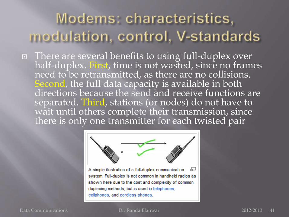
A full-duplex (FDX), or sometimes double-duplex system, allows communication in both directions, and, unlike half-duplex, allows this to happen simultaneously.
Land-line telephone networks are full-duplex, since they allow both callers to speak and be heard at the same time. A good analogy for a full-duplex system would be a two-lane road with one lane for each direction.
Two-way radios can be designed as full-duplex systems, transmitting on one frequency and receiving on another. This is also called frequency-division duplex.
Data Communications Dr. Randa Elanwar 2012-2013 40
There are several benefits to using full-duplex over half-duplex. First, time is not wasted, since no frames need to be retransmitted, as there are no collisions. Second, the full data capacity is available in both directions because the send and receive functions are separated. Third, stations (or nodes) do not have to wait until others complete their transmission, since there is only one transmitter for each twisted pair
Data Communications Dr. Randa Elanwar 2012-2013 41

Transmission modes and standards Modems are generally classified by the amount of
data they can send in a given unit of time.
The terms bit rate (the number of bits per second) and baud rate are used incorrectly much of the time. They are not the same.
A bit is a unit of information, a baud is a unit of signaling speed, the number of times a signal on a communications circuit changes. ITU-T now recommends the term baud rate be replaced by the term symbol rate.
Data Communications Dr. Randa Elanwar 2012-2013 42

Transmission modes and standards
The bit rate and the symbol rate (or baud rate) are the same only when one bit is sent on each symbol. If we use QAM or TCM, the bit rate would be several times the baud rate.
Better modems can change data rates during transmission to reduce the rate in case of noisy transmission (fast retrain).
Data Communications Dr. Randa Elanwar 2012-2013 43
Modes of transmission (Data flow perspective):
Simplex transmission
Television and radio
Half-duplex (HDX) transmission
Walkie-talkie, terminal
Full-duplex (FDX) transmission
Telephone, computer to computer
Data Communications Dr. Randa Elanwar 2012-2013 44

Modes of transmission (Physical connection perspective):
Parallel transmission
Fast
Simple
Line cost
Serial transmission
Complicated transmitter and receiver
Decomposing and reconstructing
Data Communications Dr. Randa Elanwar 2012-2013 45
Modes of transmission (Timing perspective): Asynchronous transmission
Start/stop bits for character synchronization
Mark (1or stop) /space (0 or start ) bits for bit synchronization
Simple, inexpensive, slow speed transmission
For personal computer
Synchronous transmission Clock circuitry
One to four synchronization characters for each block of data
Large amount of data on dedicated line
Data Communications Dr. Randa Elanwar 2012-2013 46
There are many different types of modems available today.
Most modems support several standards so that they can communicate with a variety of different modems.
Modem standards: V. by ITU-T (International Telecommunications Union-
Telephony Sector) V. bis & V.ter
MNP standard (Microcom networking protocols) Modem standard: V.34 (28.8 Kbps) Data compression standard: V.42bis & MNP 5 Error control standard: V.42 & MNP 4
Data Communications Dr. Randa Elanwar 2012-2013 47

V.22
1200-2400 baud/bps, FSK
V.32 and V.32bis
full duplex at 9600 bps (2400 baud at QAM)
bis uses TCM to achieve 14,400 bps.
V.34 and V.34bis
Works best for phone networks using digital transmission beyond the local loop to reduce noise. Up to 28,800 bps (TCM)
bis up to 36,600 with TCM
Data Communications Dr. Randa Elanwar 2012-2013 48

V.42bis
data compression modems, accomplished by run length encoding, code book compression, Huffman encoding and adaptive Huffman encoding
MNP5 - uses Huffman encoding to attain 1.3:1 to 2:1 compression.
bis uses Lempel-Ziv encoding and attains 3.5:1 to 4:1.
V.42bis compression can be added to almost any modem standard effectively tripling the data rate.
Data Communications Dr. Randa Elanwar 2012-2013 49

Data Communications Dr. Randa Elanwar 2012-2013 50

Modem Functions: Convert signals
Reverse channel for signal one another
Auto dial/auto answer
Modem diagnostics for accuracy checking
Modems Handshaking: Exchange signals between modems
Test the characteristics of circuit and quality
determine baud rate, modulation technique and error control
Data Communications Dr. Randa Elanwar 2012-2013 51
Modem types:
Simplex, half-duplex, full-duplex transmission modems
Asynchronous or synchronous transmission modems
Acoustically coupled modems (portable)
Limited distance modems/short haul modems (less than 20 miles)
Modem eliminators/null modems (cable less than several thousand feet)
Facsimile modems Error correction and data compression
Modem for fiber-optics circuits Digital-electrical to digital-optical
Data Communications Dr. Randa Elanwar 2012-2013 52
Cable modems DTE (data terminal equipment) to
cable television system cable Internet and cable television system
problems
Cellular modems Wired/wireless modems ISDN modems CSU/DSU Enhanced V.34 modems 56-kbps modems Digital simultaneous voice data
(DSVD) Analog simultaneous voice data
(ASVD) Asymmetric digital subscriber line
(ADSL)

Modem selection criteria:
Digital or analog signals
Asynchronous or synchronous
Speed
Distance
Type of line
Cost
Use compatible modems for both ends
Data Communications Dr. Randa Elanwar 2012-2013 53