data communications & computer networks chapter2 protocols...
TRANSCRIPT

1
1
Data Communications &
Computer Networks
Chapter 2
Protocols and Architecture
Fall 2008
Agenda
• Protocol architecture
• The Layered network Model
• The OSI reference model
—Layers of OSI
• The TCP/IP model
—Layers of TCP/IP
• Comparison between OSI and TCP/IP models

2
3
Protocol Architecture
4
Need For Protocol Architecture
• Used for communications between entities in a system
• Must speak the same language
• Entities
—User applications
—e-mail facilities
—terminals
• Systems
—Computer
—Terminal
—Remote sensor
3
5
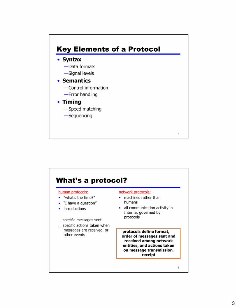
Key Elements of a Protocol
• Syntax
—Data formats
—Signal levels
• Semantics
—Control information
—Error handling
• Timing
—Speed matching
—Sequencing
6
What’s a protocol?
human protocols:
• “what’s the time?”
• “I have a question”
• introductions
… specific messages sent
… specific actions taken when messages are received, or other events
network protocols:
• machines rather than humans
• all communication activity in Internet governed by protocols
protocols define format, order of messages sent and received among network entities, and actions taken on message transmission,
receipt
4
7
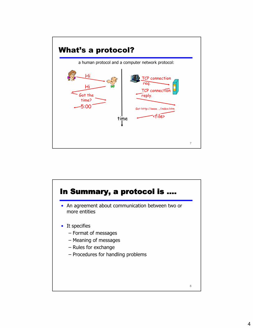
What’s a protocol?
a human protocol and a computer network protocol:
Hi
Hi
Got thetime?
5:00
TCP connectionreq.
TCP connectionreply.
Get http://www…./index.htm
<file>time
8
In Summary, a protocol is ....In Summary, a protocol is ....In Summary, a protocol is ....In Summary, a protocol is ....
• An agreement about communication between two or more entities
• It specifies
– Format of messages
– Meaning of messages
– Rules for exchange
– Procedures for handling problems

5
9
Protocol Specification
• As designers, we can specify a protocol using Space-Time Diagrams
• Internet Protocols are formalized by RFCs (Request For Comment) which are administered by IETF (Internet Engineering Task Force)
10
Space-Time Diagrams
• Defines causal ordering
• Defines indication/request/response actions

6
11
Protocol Architecture
• Task of communication broken up into modules
• For example file transfer could use three modules
—File transfer application
—Communication service module
—Network access module
12
The layered network model
7
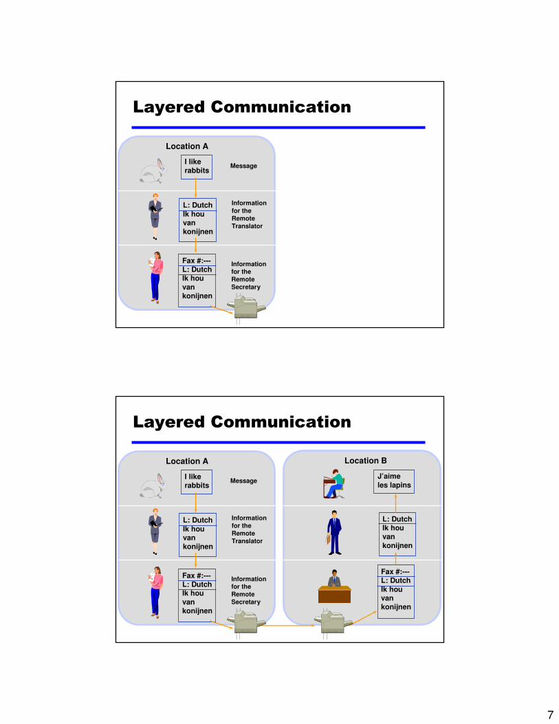
Layered Communication
I like rabbits
L: Dutch
Ik hou vankonijnen
Fax #:---L: DutchIk hou
vankonijnen
Message
Information
for the
Remote
Translator
Informationfor the
Remote
Secretary
Location A
Layered Communication
I like rabbits
L: Dutch
Ik hou vankonijnen
L: DutchIk hou van
konijnen
Fax #:---L: DutchIk hou
vankonijnen
Fax #:---L: Dutch
Ik hou vankonijnen
J’aime
les lapins
Information
for the
Remote
Translator
Informationfor the
Remote
Secretary
Location A Location B
Message
8
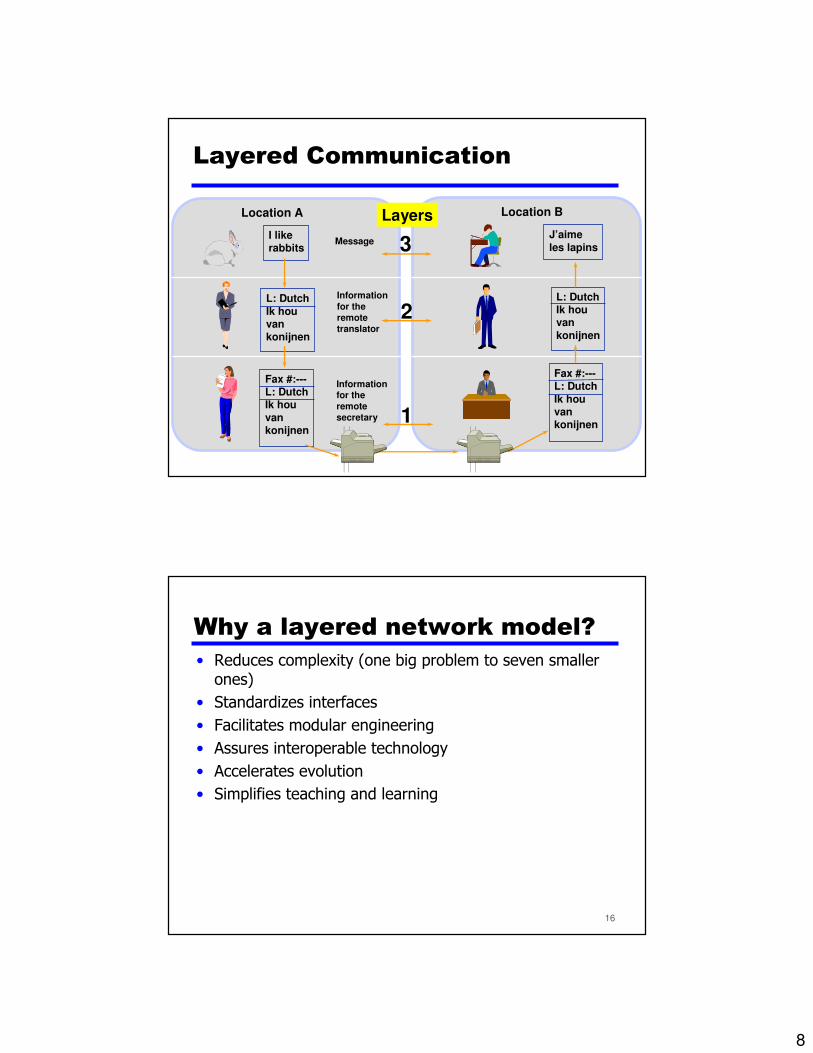
Layered Communication
I like rabbits
L: Dutch
Ik hou vankonijnen
L: DutchIk hou van
konijnen
Fax #:---L: DutchIk hou
vankonijnen
Fax #:---L: Dutch
Ik hou vankonijnen
J’aime
les lapins
Information
for the
remote
translator
Informationfor the
remote
secretary
Location A Location B
1
2
3
Layers
Message
16
Why a layered network model?
• Reduces complexity (one big problem to seven smaller ones)
• Standardizes interfaces
• Facilitates modular engineering
• Assures interoperable technology
• Accelerates evolution
• Simplifies teaching and learning
9
17
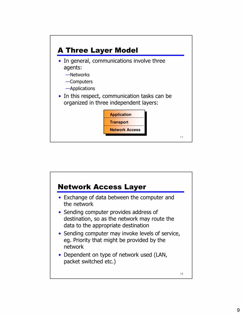
A Three Layer Model
• In general, communications involve three agents:
—Networks
—Computers
—Applications
• In this respect, communication tasks can be organized in three independent layers:
Application
Transport
Network Access
18
Network Access Layer
• Exchange of data between the computer and the network
• Sending computer provides address of destination, so as the network may route the data to the appropriate destination
• Sending computer may invoke levels of service, eg. Priority that might be provided by the network
• Dependent on type of network used (LAN, packet switched etc.)

10
19
Transport Layer
• Reliable data exchange
• Independent of network being used
• Independent of application
20
Application Layer
• Contains the logic to support different user applications
• For each type of application, e.g. e-mail, file transfer, a separate module is needed

11
21
Protocol Architectures and
Networks
22
Addressing Requirements
• Two levels of addressing required
—Each computer needs unique network address
—Each application on a (multi-tasking) computer needs a unique address within the computer
• The Service Access Point (SAP)
• The port on TCP/IP stacks

12
23
Protocols in Simplified
Architecture
24
Protocol Data Units (PDU)
• At each layer, protocols are used to communicate
• Control information is added to user data at each layer
• Transport layer may fragment user data to make it more manageable
• This gives a transport protocol data unit
• Each fragment has a transport header added—Destination SAP
—Sequence number for each PDU
—Error-detection code

13
25
Protocol Data Units
26
Network PDU
• Adds network header
—network address for destination computer
• The network must know to which computer in the network the data are to be delivered
—Facilities requests
• The network access protocol might want the network to make use of certain facilities, such as priority

14
27
Operation of a Protocol
Architecture
28
Standardized Protocol
Architectures• Required for devices to communicate
• Vendors have more marketable products
• Customers can insist on standards-based equipment
• As computers dropped in price, joining them together became verypopular – i.e. they were ‘Networked’ to share information.
• But how are they to talk to each other? If company A sold a computer that cannot talk to company B’s computer, then lifebecomes very difficult.
• What is needed is a standard – a set of rules that every companywill obey, so that their machines will know how to communicate.
• Two standards:
— OSI reference model• Never lived up to early promises
— TCP/IP model• Most widely used

15
29
Why is it important to have
standards for communicating?
• To enable devices to communicate together
• To allow devices to be guaranteed as reliable
• To allow purchasers to know the device willwork
30
The OSI reference model

16
31
The OSI layered model• Open Systems Interconnection (OSI) was an effort to standardize
networking that was started in 1982 by the International Organization for Standardization (ISO), along with the ITU-T.
• Prior to OSI, according to its proponents, networking was largely vendor-developed and proprietary
• OSI was an industry effort, attempting to get everyone to agree tocommon network standards to provide multi-vendor interoperability. It wascommon for large networks to support multiple network protocol suites, with many devices unable to talk to other devices because of a lack ofcommon protocols between them.
• However while OSI developed its networking standards, TCP/IP came intowidespread use as the de facto standard.
• The OSI reference model (which actually predates the OSI protocolwork, dating to 1977) was a major advance in the teaching of networkconcepts. It promoted the idea of a common model of protocol layers, defining interoperability between network devices and software.
32
OSI - The Model
• A layer model
• Each layer performs a subset of the required communication functions
• Each layer relies on the next lower layer to perform more primitive functions
• Each layer provides services to the next higher layer
• Changes in one layer should not require changes in other layers
17
33
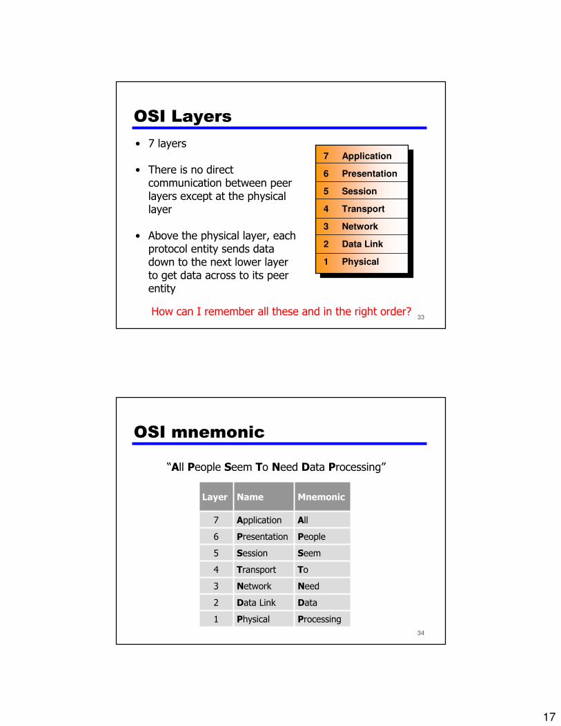
OSI Layers
• 7 layers
• There is no direct communication between peer layers except at the physical layer
• Above the physical layer, each protocol entity sends data down to the next lower layer to get data across to its peer entity
7 Application
6 Presentation
5 Session
4 Transport
3 Network
2 Data Link
1 Physical
How can I remember all these and in the right order?
34
OSI mnemonic
“All People Seem To Need Data Processing”
ProcessingPhysical1
Data Data Link2
NeedNetwork3
ToTransport4
SeemSession5
PeoplePresentation6
AllApplication7
MnemonicNameLayer

18
35
Other OSI mnemonics
“All Pretty Serious Teenagers Never Do Physics ”or:
“Please Do Not Tell Sales People Anything ”
Physics
Do
Never
Teenagers
Serious
Pretty
All
Mnemonic(top to bottom)
PleasePhysical1
DoData Link2
NotNetwork3
TellTransport4
SalesSession5
PeoplePresentation6
AnythingApplication7
Mnemonic (from bottom up)
NameLayer
36
Host and Media layers
7 Application
6 Presentation
5 Session
4 Transport
3 Network
2 Data Link
1 Physical
Host layers:Host layers: Provide
accurate data delivery between
computers
Media layers:Media layers: Control
physical delivery of messages
over the network}}

19
37
Basic Rules in the OSI model• Each layer can only talk to the one above it andbelow it— e.g. The ‘Network’ layer can only pass information to the
‘Transport’ layer above it and the ‘Data Link’ layer below it.
• Passing information from one layer to another isdone in a standard way— This means that if company ‘A’ has written some software for
the ‘Transport’ layer – and company ‘B’ has written somesoftware for the ‘Network’ layer – then they are guaranteed tobe able talk to each other.
• Any layer does not care or need to know how thelayers beneath it work— It will assume that the information it needs, is going to be
presented in a standard way. This makes it much simpler todesign the layer itself.
38
Description of OSI layers

20
39
Layer 1: Physical layer• The physical layer defines all the electrical and physical specifications for devices. In
particular, it defines the relationship between a device and a physical medium. Thisincludes the layout of pins, voltages and cable specifications. Hubs, repeaters, network adapters and Host Bus Adapters are physical-layer devices.
• The physical layer is concerned primarily with the interaction of a single device witha medium. The physical layer will tell one device how to transmit to the medium, andanother device how to receive from it, but not, with modern protocols, how to gainaccess to the medium. Physical layer standards such as RS-232 use physical wires tocontrol access to the medium.
• The major functions and services performed by the physical layer are:
— Establishment and termination of a connection to a medium.
— Participation in the process whereby the communication resources areeffectively shared among multiple users. For example, floe control.
— Modulation, or conversion between the representation of digital data in userequipment and the corresponding signals transmitted over a communicationschannel. These are signals operating over the physical cabling (such as copperand optical fiber) or over a radio link.
40
Layer 2: Data Link layer (1/2)• The Data Link layer provides the functional and procedural means to
transfer data between network entities and to detect and possibly correcterrors that may occur in the Physical layer.
• Originally, this layer was intended for point-to-point and point-to-multipointmedia, characteristic of wide area media in the telephone system. Localarea network architecture, which included broadcast-capable multiaccessmedia, was developed independently of the ISO work, in IEEE Project
802. IEEE work assumed sublayering and management functions notrequired for WAN use.
• Both WAN and LAN services arrange bits, from the physical layer, intological sequences called frames. Not all physical layer bits necessarily gointo frames, as some of these bits are purely intended for physical layer
functions. For example, every fifth bit of the FDDI bit stream is not used bythe data link layer.
21
41
Layer 2: Data Link layer (2/2)• WAN Protocol Architecture
— Connection-oriented WAN data link protocols, in addition to framing, detect andmay correct errors. They also are capable of controlling the rate of transmission. A WAN data link layer might implement a sliding window flow control andacknowledgment mechanism to provide reliable delivery of frames.
• IEEE 802 LAN Architecture*
— Practical, connectionless LANs began with the pre-IEEE Ethernet specification, which is the ancestor of the IEEE 802.3. This layer manages the interaction ofdevices with a shared medium, which is the function of a Media Access Control (MAC) sublayer. Above this MAC sublayer is the media-independent IEEE 802.2Logical Link Control (LLC) sublayer, which deals with addressing andmultiplexing on multiaccess media.
• While IEEE 802.3 is the dominant wired LAN protocol and IEEE 802.11 thewireless LAN protocol, obsolescent MAC layers include Token Ring andFDDI. The MAC sublayer detects but does not correct errors.
* this specification is covered thoroughly in the ACOE322 course.
42
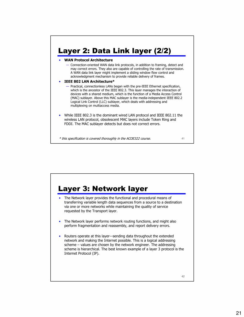
Layer 3: Network layer• The Network layer provides the functional and procedural means of
transferring variable length data sequences from a source to a destinationvia one or more networks while maintaining the quality of service
requested by the Transport layer.
• The Network layer performs network routing functions, and might alsoperform fragmentation and reassembly, and report delivery errors.
• Routers operate at this layer—sending data throughout the extendednetwork and making the Internet possible. This is a logical addressingscheme – values are chosen by the network engineer. The addressingscheme is hierarchical. The best known example of a layer 3 protocol is theInternet Protocol (IP).

22
43
Layer 4: Transport layer• The Transport layer provides transparent transfer of data between end
users, providing reliable data transfer services to the upper layers.
• It controls the reliability of a given link through flow control, segmentation/desegmentation, and error control. Some protocols are state andconnection oriented. This means that the transport layer can keep track ofthe segments and retransmit those that fail.
• It converts messages into TCP segments or User Datagram Protocol (UDP), Stream Control Transmission Protocol (SCTP).
• Perhaps an easy way to visualize the Transport Layer is to compare it witha Post Office, which deals with the dispatch and classification of mail andparcels sent. Do remember, however, that a post office manages the outerenvelope of mail. Higher layers may have the equivalent of doubleenvelopes, such as cryptographic Presentation services that can be read bythe addressee only.
44
Layer 5: Session layer• The Session layer controls the dialogues/connections (sessions) between
computers.
• It establishes, manages and terminates the connections between the localand remote application.
• It provides for either full-duplex or half-duplex operation, and establishescheckpointing, interruption, termination, and restart procedures. The OSI model made this layer responsible for "graceful close" of sessions, which isa property of TCP, and also for session checkpointing and recovery, whichis not usually used in the Internet protocols suite.

23
45
Layer 6: Presentation layer• The Presentation layer transforms the data to provide a standard interface
for the Application layer.
• MIME* encoding, data encryption and similar manipulation of thepresentation are done at this layer to present the data as a service orprotocol that the developer sees fit.
• Examples of this layer are converting an 8-bit-coded text file to an ASCII-coded file (character encoding) and other data structures into and out ofXML.
* Multipurpose Internet Mail Extensions (MIME) is an internet standard that extends theformat of email.
46
Layer 7: Application layer• The Application layer interfaces directly to and performs common application
services for the application processes; it also issues requests to the presentationlayer.
• Note that this layer provides services to user-defined application processes, and notto the end user. For example, it defines a file transfer protocol, but the end usermust go through an application process to invoke file transfer. The OSI model doesnot include human interfaces.
• The common application services sublayer provides functional elements including theRemote Operations Service Element (comparable to Internet Remote ProcedureCall), Association Control, and Transaction Processing.
• Above the common application service sublayer are functions meaningful to userapplication programs, such as messaging (X.400), directory (X.500), file transfer(FTAM), etc.
24
47
James Bond and OSI analogy• James Bond meets Number One on the 7th floor (application) of the spy headquarters
building. Number One gives Bond a secret message that must get through to the US Embassy across town.
• Bond proceeds to the 6th floor (presentation) where the message is translated into anintermediary language, encrypted and miniaturized.
• Bond takes the elevator to the 5th (session) floor where Security checks the message tobe sure it is all there and puts some checkpoints in the message so his counterpart at theUS end can be sure he’s got the whole message.
• On the 4th floor (transport) the message is analyzed to see if it can be combined withsome other small messages that need to go to the US end. Also if the message was verylarge it might be broken into several small packages so other spies can take it and have itreassembled on the other end.
• The 3rd floor (Network) personnel check the address on the message and determinewho the addressee is and advising Bond of the fastest route to the Embassy.
• On the 2nd floor (Data link) the message is put into a special courier pouch (packet). Itcontains the message, the sender and destination ID. It also warns the recipient if otherpieces are still coming.
• Bond proceeds to the 1st floor (Physical) where Q has prepared the Aston Martin for thetrip to the Embassy. Bond departs for the US Embassy with the secret packet in hand.
• On the other end the process is reversed. Bond proceeds from floor to floor where themessage is decoded. The US Ambassador is very grateful the message got through safely. "Bond, please tell Number One I’ll be glad to meet him for dinner tonight".
7 Application
6 Presentation
5 Session
4 Transport
3 Network
2 Data Link
1 Physical
Host A
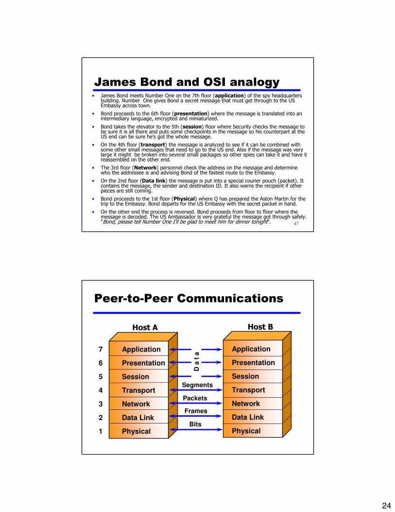
Peer-to-Peer Communications
Application
Presentation
Session
Transport
Network
Data Link
PhysicalBits
Frames
Packets
Segments
Host B
D a
t a

25
Data Encapsulation
Application
Presentation
Session
Transport
Network
Physical
Data Link
Application
Presentation
Session
Transport
Network
Physical
Data Link
Host A Host B
Data} {
• The process of moving data from host A to host B is known as data encapsulation• the data is being wrapped in the appropriate protocol
header so it can be properly received.
Data Encapsulation
DataNetworkHeader
Application
Presentation
Session
Transport
Network
Physical
Data Link
Application
Presentation
Session
Transport
Network
Physical
Data Link
Host A Host B
Data} {
At the network layer, a network header is added to the data. This header contains information required to complete the transfer, such as source and destination logical addresses.

26
Data Encapsulation
FrameHeader
FrameTrailer
DataNetworkHeader
Application
Presentation
Session
Transport
Network
Physical
Data Link
Application
Presentation
Session
Transport
Network
Physical
Data Link
Host A Host B
} {Data
NetworkHeader
Data
The packet from the network layer is then passed to the data link layer where a frame header and a frame trailer are added thus creating a data link frame.
Data Encapsulation
FrameHeader
FrameTrailer
DataNetworkHeader
Application
Presentation
Session
Transport
Network
Physical
Data Link
Application
Presentation
Session
Transport
Network
Physical
Data Link
Host A Host B
} {Data
NetworkHeader
Data
• Finally, the physical layer provides a service to the data link layer.
• This service includes encoding the data link frame into a pattern of 1s and 0s for transmission on the medium (usually a wire).
1011110101001001
27
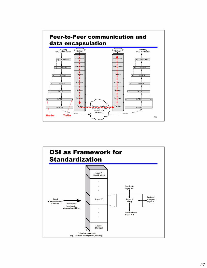
53
Peer-to-Peer communication and
data encapsulation
Header Trailer
54
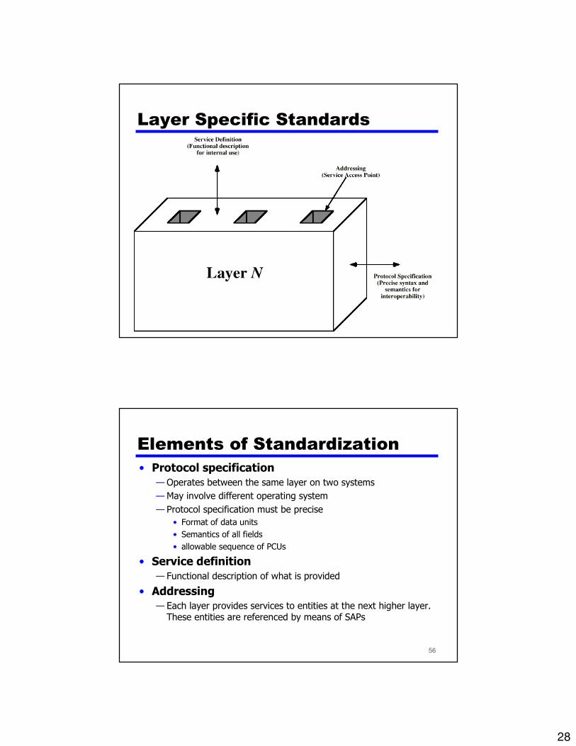
OSI as Framework for
Standardization
28
55
Layer Specific Standards
56
Elements of Standardization
• Protocol specification
— Operates between the same layer on two systems
— May involve different operating system
— Protocol specification must be precise
• Format of data units
• Semantics of all fields
• allowable sequence of PCUs
• Service definition
— Functional description of what is provided
• Addressing
— Each layer provides services to entities at the next higher layer. These entities are referenced by means of SAPs
29
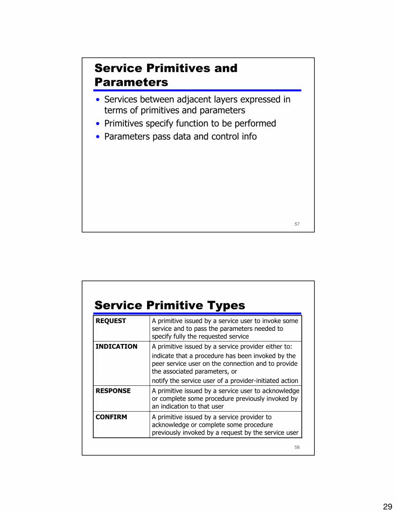
57
Service Primitives and
Parameters
• Services between adjacent layers expressed in terms of primitives and parameters
• Primitives specify function to be performed
• Parameters pass data and control info
58
Service Primitive Types
A primitive issued by a service provider to acknowledge or complete some procedure previously invoked by a request by the service user
CONFIRM
A primitive issued by a service user to acknowledge or complete some procedure previously invoked by an indication to that user
RESPONSE
A primitive issued by a service provider either to:
indicate that a procedure has been invoked by the peer service user on the connection and to provide the associated parameters, or
notify the service user of a provider-initiated action
INDICATION
A primitive issued by a service user to invoke some service and to pass the parameters needed to specify fully the requested service
REQUEST

30
59
Timing Sequence for Service
Primitives
60
Use of a Relay
network node
L3 L3
L2 L2
L1 L1
e.g. router
31
61
Benefits of OSI model• Any hardware that meets the OSI standard will be able to
communicate with any other hardware that also meets thestandard
• Any software that meets the OSI standard will be able tocommunicate with any other hardware or software that also meetsthe standard
• Consumers are given a wider choice since hardware/software fromany manufacturer will work together
• OSI is independent of country, it doesn't matter where thehardware/software is made
• OSI is not dependent on the operating system used
• The protocols for OSI are defined at each stage
• Any errors that occur are handled in each layer
• The different layers can operate automatically
62
The OSI model vs the Real World
• The most major difficulty with the OSI model is that is does not map well to the real world!
• The OSI was created after many of today’s protocols were already in production use. These existing protocols, such as TCP/IP, were designed and built around the needs of real users with real problems to solve. The OSI model was created by academicians for academic purposes.
• The OSI model is a very poor standard, but it's the only well-recognized standard we have which describes networked applications.
• The easiest way to deal with the OSI model is to map the real-world protocols to the model, as well as they can be mapped.
32
63
OSI modem summary
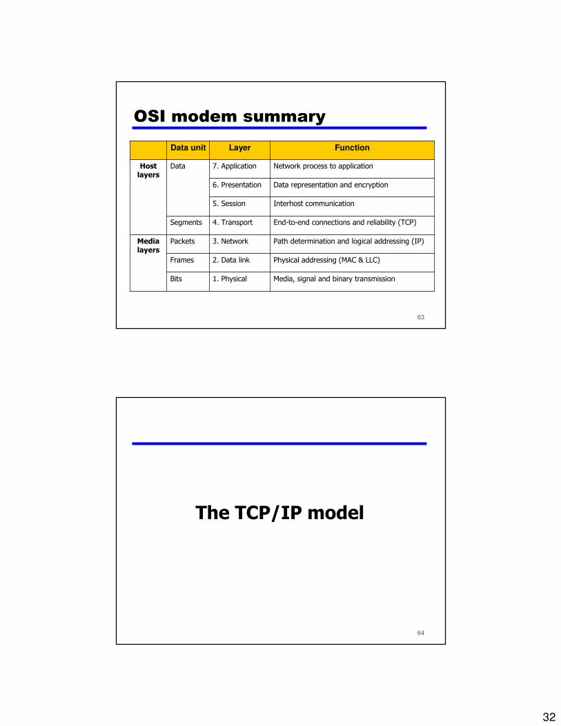
Media, signal and binary transmission1. PhysicalBits
Physical addressing (MAC & LLC)2. Data linkFrames
Path determination and logical addressing (IP)3. NetworkPacketsMedialayers
End-to-end connections and reliability (TCP)4. TransportSegments
Interhost communication5. Session
Data representation and encryption6. Presentation
Network process to application7. ApplicationDataHostlayers
FunctionLayerData unit
64
The TCP/IP model
33
65
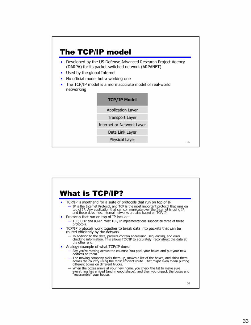
The TCP/IP model
• Developed by the US Defense Advanced Research Project Agency (DARPA) for its packet switched network (ARPANET)
• Used by the global Internet
• No official model but a working one
• The TCP/IP model is a more accurate model of real-world networking
Data Link Layer
Physical Layer
Internet or Network Layer
Transport Layer
Application Layer
TCP/IP Model
66
What is TCP/IP?• TCP/IP is shorthand for a suite of protocols that run on top of IP.
— IP is the Internet Protocol, and TCP is the most important protocol that runs on top of IP. Any application that can communicate over the Internet is using IP, and these days most internal networks are also based on TCP/IP.
• Protocols that run on top of IP include: — TCP, UDP and ICMP. Most TCP/IP implementations support all three of these
protocols.
• TCP/IP protocols work together to break data into packets that can be routed efficiently by the network. — In addition to the data, packets contain addressing, sequencing, and error
checking information. This allows TCP/IP to accurately reconstruct the data at the other end.
• Analogy example of what TCP/IP does:— Say you’re moving across the country: You pack your boxes and put your new
address on them. — The moving company picks them up, makes a list of the boxes, and ships them
across the country using the most efficient route. That might even mean putting different boxes on different trucks.
— When the boxes arrive at your new home, you check the list to make sure everything has arrived (and in good shape), and then you unpack the boxes and “reassemble” your house.
34
67
TCP/IP Physical Layer• The Physical layer is responsible for encoding and transmission of
data over network communications media. It operates with data inthe form of bits that are sent from the Physical layer of the sending(source) device and received at the Physical layer of the destinationdevice.
• Ethernet, Token Ring, hubs, repeaters, cables and connectors arestandard network devices that function at the Physical layer.
• The Physical layer is also considered the domain of many hardware-related network design issues, such as LAN and WAN topology andwireless technology.
68
TCP/IP Data Link Layer• The link layer, which is the method used to move packets from the network
layer on two different hosts, is not really part of the Internet protocol suite, because IP can run over a variety of different link layers.
• The processes of transmitting packets on a given link layer and receivingpackets from a given link layer can be controlled both in the software device driver for the network card, as well as on firmware or specialistchipsets. These will perform data link functions such as adding a packet header to prepare it for transmission, then actually transmit the frame overa physical medium.
• For Internet access over a dial-up modem, IP packets are usuallytransmitted using PPP. For broadband Internet access such as ADSL, PPPoEis often used. On a local wired network, Ethernet is usually used, and onlocal wireless networks, IEEE802.11 is usually used. For WANs, either PPP over E1-carrier lines, Frame Relay, ATM, or Packet Over SONET/SDH (POS) are often used.
35
69
TCP/IP Internet (or Network) Layer
• This layer is responsible for getting data from the source network tothe destination network. This generally involves routing the packetacross a network of networks, known as an internetwork or (lower-case) internet.
• In the Internet protocol suite, IP performs the basic task of gettingpackets of data from source to destination. IP can carry data for a number of different upper layer protocols; these protocols are eachidentified by a unique protocol number. For example, ICMP (used totransmit diagnostic information about IP transmission) and IGMP(used to manage IP multicat data) are protocols 1 and 2, respectively, which are layered on top of IP.
• All routing protocols, such as OSPF, and RIP are also part of thenetwork layer. What makes them part of the network layer is thattheir payload is totally concerned with management of the networklayer.
70
TCP/IP Transport Layer (1/2)• The Transport layer's responsibilities include end-to-end message transfer
capabilities independent of the underlying network, along with error control, fragmentation and flow control. End to end message transmission or connectingapplications at the transport layer can be categorized as either:— Connection-oriented (reliable)— Connectionless (unreliable)
• The transport layer can be thought of literally as a transport mechanism e.g. a vehicle whose responsibility is to make sure that its contents (passengers/goods) reach its destination safely and soundly, unless a higher or lower layer is responsiblefor safe delivery. Some applications, such as Voice over IP (VoIP) can toleratedropped packets, but not delay or reordering that would be caused by a reliabletransport.
• The transport layer provides this service of connecting applications together throughthe use of ports. Since IP provides only a best effort delivery, the transport layer isthe first layer of the TCP/IP stack to offer reliability.
• For example, Transmission Control Protocol (TCP) is a connection-orientedprotocol that addresses numerous reliability issues to provide a reliable byte stream.
36
71
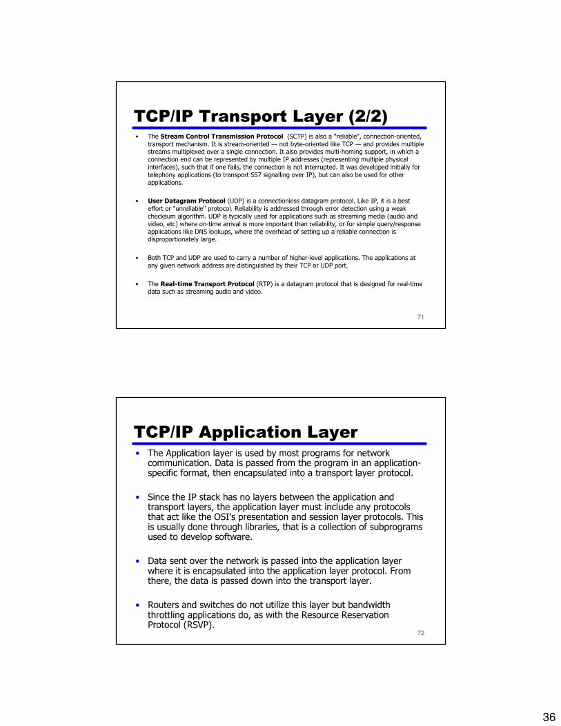
TCP/IP Transport Layer (2/2)• The Stream Control Transmission Protocol (SCTP) is also a "reliable", connection-oriented,
transport mechanism. It is stream-oriented — not byte-oriented like TCP — and provides multiplestreams multiplexed over a single connection. It also provides multi-homing support, in which a connection end can be represented by multiple IP addresses (representing multiple physicalinterfaces), such that if one fails, the connection is not interrupted. It was developed initially fortelephony applications (to transport SS7 signalling over IP), but can also be used for otherapplications.
• User Datagram Protocol (UDP) is a connectionless datagram protocol. Like IP, it is a best effort or "unreliable" protocol. Reliability is addressed through error detection using a weakchecksum algorithm. UDP is typically used for applications such as streaming media (audio andvideo, etc) where on-time arrival is more important than reliability, or for simple query/responseapplications like DNS lookups, where the overhead of setting up a reliable connection isdisproportionately large.
• Both TCP and UDP are used to carry a number of higher-level applications. The applications atany given network address are distinguished by their TCP or UDP port.
• The Real-time Transport Protocol (RTP) is a datagram protocol that is designed for real-timedata such as streaming audio and video.
72
TCP/IP Application Layer• The Application layer is used by most programs for network
communication. Data is passed from the program in an application-specific format, then encapsulated into a transport layer protocol.
• Since the IP stack has no layers between the application andtransport layers, the application layer must include any protocolsthat act like the OSI's presentation and session layer protocols. Thisis usually done through libraries, that is a collection of subprogramsused to develop software.
• Data sent over the network is passed into the application layerwhere it is encapsulated into the application layer protocol. Fromthere, the data is passed down into the transport layer.
• Routers and switches do not utilize this layer but bandwidth throttling applications do, as with the Resource Reservation Protocol (RSVP).

37
73
TCP protocol• TCP stands for Transmission Control Protocol.
• TCP establishes a reliable connection between two applications over the network (connection-oriented). This means that TCP guarantees accurate, sequential delivery of your data. If something goes wrong, TCP reports an error, so you always know whether your data arrived at the other end.
Here’s how it works:
• Every TCP connection is uniquely identified by four numbers:— source IP address
— source port
— destination IP address
— destination port
• Typically, a client will use a random port number, but a server will use a “well known” port number, e.g. 25=SMTP (email), 80=HTTP (Web) and so on. Because every TCP connection is unique, even though many people may be making requests to the same Web server, TCP/IP can identify your packets among the crowd.
• In addition to the port information, each TCP packet has a sequence number. Packets may arrive out of sequence (they may have been routed differently, or one may have been dropped), so the sequence numbers allow TCP to reassemble the packets in the correct order and to request retransmission of any missing packets.
• TCP packets also include a checksum to verify the integrity of the data. Packets that fail checksum get retransmitted.
74
UDP protocol• Alternative to TCP is the User Datagram Protocol
• UDP is a fast, unreliable, connectionless protocol, that is suitable for some applications.
• Unreliable means there is no sequencing, no guaranteed delivery (no automatic retransmission of lost packets) and sometimes no checksums.
• Fast means there is no connection setup time, unlike TCP. In reality, once a TCP session is established, packets will go just as fast over a TCP connection as over UDP.
• UDP is useful for applications such as streaming audio that don’t care about dropped packets and for applications such as TFTP that inherently do their own sequencing and checksums. Also, applications such as NFS that usually run on very reliable physical networks and which need fast, connectionless transactions use UDP.
38
75
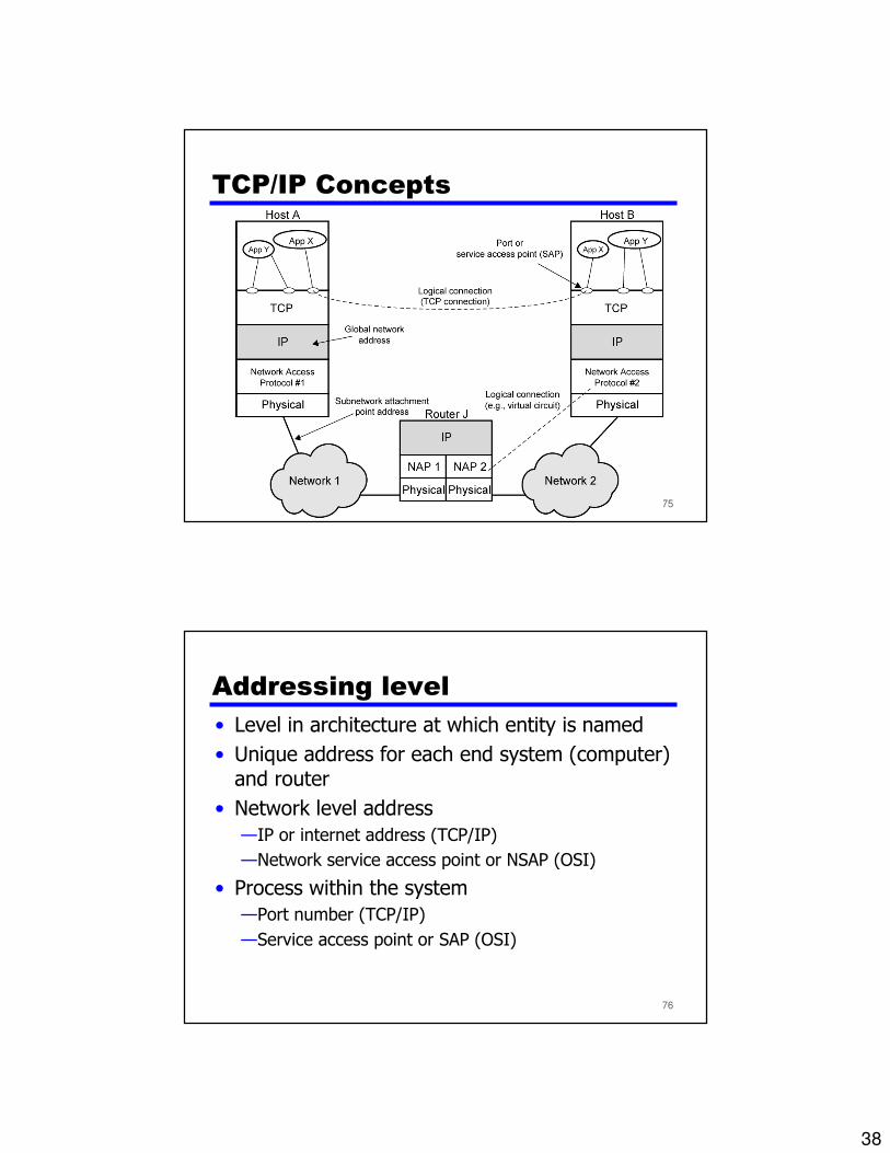
TCP/IP Concepts
76
Addressing level
• Level in architecture at which entity is named
• Unique address for each end system (computer) and router
• Network level address
—IP or internet address (TCP/IP)
—Network service access point or NSAP (OSI)
• Process within the system
—Port number (TCP/IP)
—Service access point or SAP (OSI)
39
77
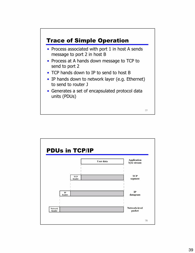
Trace of Simple Operation
• Process associated with port 1 in host A sends message to port 2 in host B
• Process at A hands down message to TCP to send to port 2
• TCP hands down to IP to send to host B
• IP hands down to network layer (e.g. Ethernet) to send to router J
• Generates a set of encapsulated protocol data units (PDUs)
78
PDUs in TCP/IP
40
79
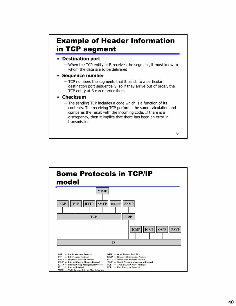
Example of Header Information
in TCP segment
• Destination port
— When the TCP entity at B receives the segment, it must know to whom the data are to be delivered
• Sequence number
— TCP numbers the segments that it sends to a particular destination port sequentially, so if they arrive out of order, the TCP entity at B can reorder them
• Checksum
— The sending TCP includes a code which is a function of its contents. The receiving TCP performs the same calculation and compares the result with the incoming code. If there is a discrepancy, then it implies that there has been an error in transmission.
80
Some Protocols in TCP/IP
model

41
81
Mapping examples of Real-World
protocols to OSI model
Cat-5, RS-232, 10BaseT, DSLPhysical1
Ethernet, ATM, FR, FDDI, Token Ring, PPPData Link2
IP, IPSec, RIP, OSPF Network3
TCP, UDPTransport4
SQL, SIP, NETBIOSSession5
HTTP, SMTP, SNMP, JPEG, MPEGPresentation6
Telnet, SNMP, SMTP, FTP, DNS, HTTPApplication7
Examples of common protocolsNameLayer
82
Comparison between OSI and TCP/IP models

42
83
Comparison between OSI and
TCP/IP models (1/3)
84
OSI model• Has been devised before the corresponding protocols
were invented• Has good definition of service, interface, and protocol • Fits well with object oriented programming concepts • Protocols are better hidden
TCP model• the protocols came first, the model was just a
description of the protocols• the model isn't good for any other protocols part from
TCP/IP.
Comparison between OSI and
TCP/IP models (2/3)
43
85
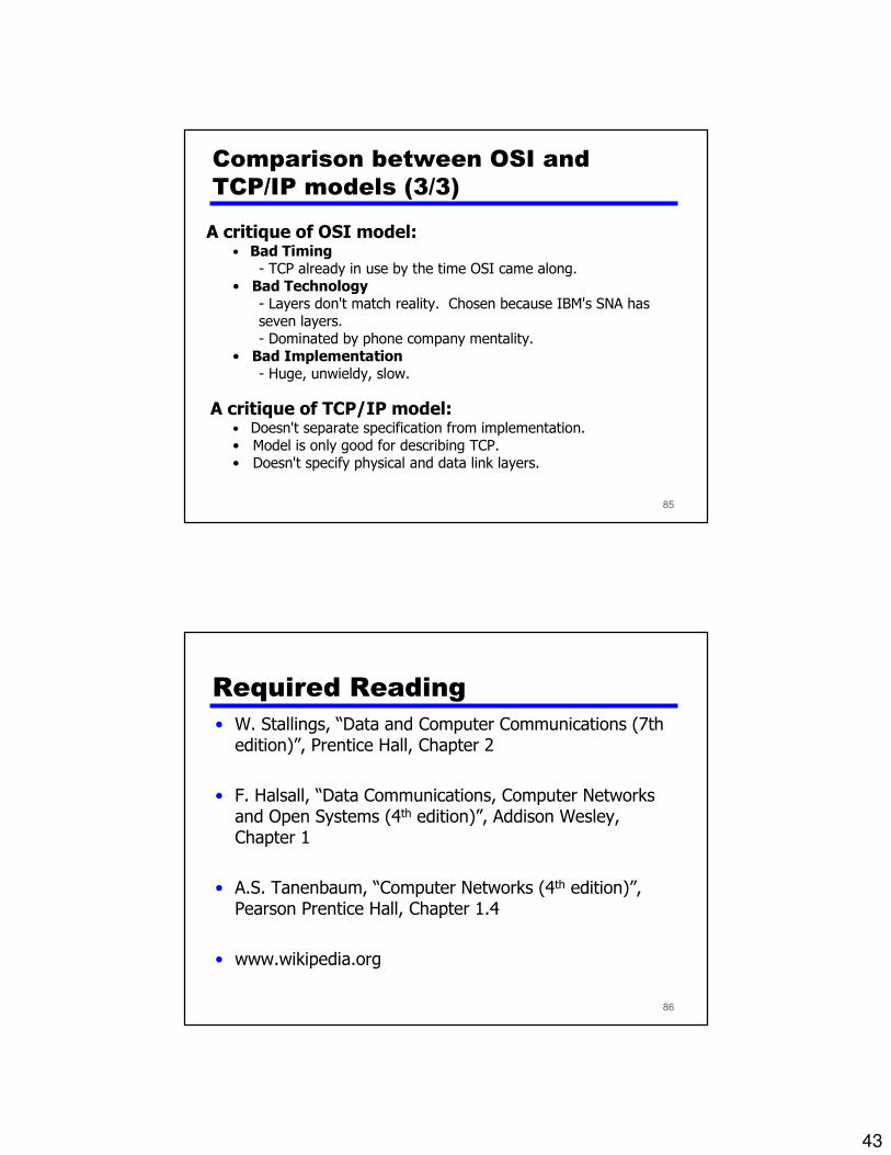
A critique of OSI model:• Bad Timing
- TCP already in use by the time OSI came along.• Bad Technology
- Layers don't match reality. Chosen because IBM's SNA has seven layers.- Dominated by phone company mentality.
• Bad Implementation- Huge, unwieldy, slow.
A critique of TCP/IP model:• Doesn't separate specification from implementation.• Model is only good for describing TCP.• Doesn't specify physical and data link layers.
Comparison between OSI and
TCP/IP models (3/3)
86
Required Reading
• W. Stallings, “Data and Computer Communications (7thedition)”, Prentice Hall, Chapter 2
• F. Halsall, “Data Communications, Computer Networks and Open Systems (4th edition)”, Addison Wesley, Chapter 1
• A.S. Tanenbaum, “Computer Networks (4th edition)”, Pearson Prentice Hall, Chapter 1.4
• www.wikipedia.org