data collection & machine diagnostics - advance · pdf filevibscanner® data collection...
TRANSCRIPT
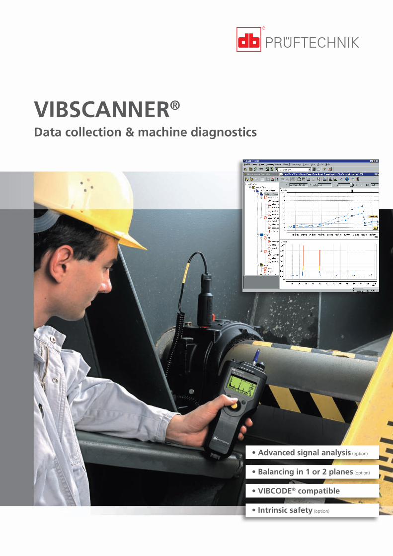
VIBSCANNER®
Data collection & machine diagnostics
• Advanced signal analysis (option)
• Balancing in 1 or 2 planes (option)
• VIBCODE® compatible
• Intrinsic safety (option)

The clever data collectorfor better maintenance
Vibration*
Bearing condition
Temperature
RPM
Process parameters
FFT spectrum
Signal analysis
Balancing
VIBSCANNER® is an offline condi-tion monitoring system for predic-tive maintenance. Its comprehen-sive measurement and analysisfunctions and the convenient joy-stick for navigation make thishandy instrument ideal for every-day inspection routines.
Well equipped
* DisplacementVelocityAccelerationacc. to the new ISO 10816-3- even at frequencies down to 2 Hz
Use trend curves to follow thedevelopment of machine de-fects.
FFT analysis with enveloping isprovided for the diagnosis ofmachine condition, bearingcondition and gear faults.
Time signals and orbits detectdamage in low-speed ma-chines, gearboxes or turbomachinery.
Signal analysis
Totally compatible with the OMNI-TREND® PC software it gives analy-sis and reporting functions in aneasy to understand format to pre-vent catastrophic machine failure,unplanned production downtimeand consequential damage to pro-cess equipment.
Trending Machine diagnosis
VIBSCANNER® measures the mostimportant machine parameters onrotating equipment. All the sensorsrequired are built into the instru-ment.
VIBSCANNER® is protected bya rugged, waterproof anddustproof case. An intrinsicallysafe version is also available.
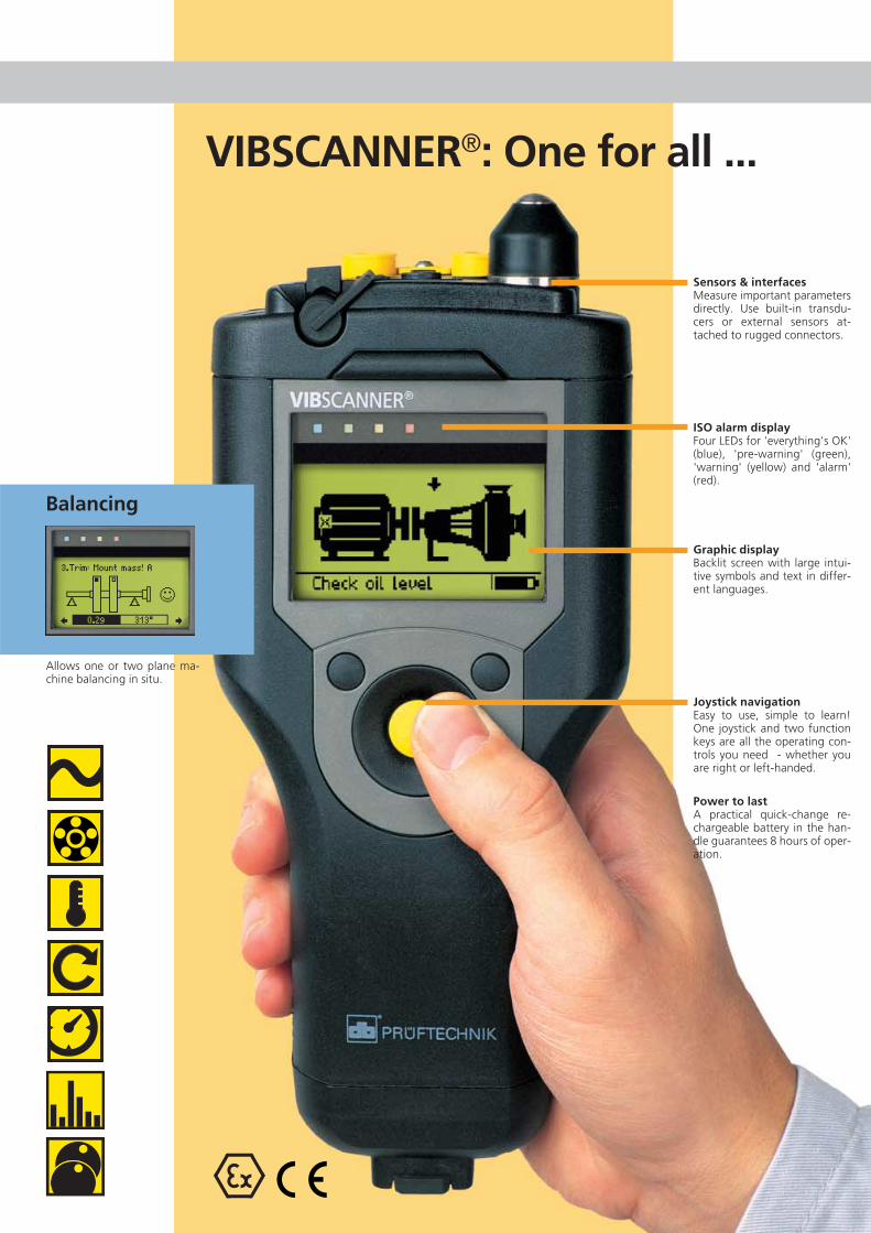
Allows one or two plane ma-chine balancing in situ.
Balancing
Graphic displayBacklit screen with large intui-tive symbols and text in differ-ent languages.
Joystick navigationEasy to use, simple to learn!One joystick and two functionkeys are all the operating con-trols you need - whether youare right or left-handed.
Power to lastA practical quick-change re-chargeable battery in the han-dle guarantees 8 hours of oper-ation.
ISO alarm displayFour LEDs for 'everything's OK'(blue), 'pre-warning' (green),'warning' (yellow) and 'alarm'(red).
Sensors & interfacesMeasure important parametersdirectly. Use built-in transdu-cers or external sensors at-tached to rugged connectors.
VIBSCANNER®: One for all ...

Take-along convenience - with built-in sensors!
Up to speed?Non-contact RPM measurementfrom distances up to 0.5 meterswith no need for reflective tape –even in poor light. A bright redpointer beam helps in directingyour aim at the rotating shaft.
Takes the heat for youThe retractable, flexible tempera-ture probe ensures optimal surfacecontact for quick, accurate read-ings – even in liquid. Or plug in anexternal probe – even IR tempera-ture guns are available.
Good vibrationsThe rugged, patented accelerome-ter measures machine vibration aswell as the high-frequency shockpulses emitted by anti-frictionbearings and cavitating pumps –for a total of three different ma-chine signals all at the same time.
Unmistakable connectorsColor-coding of the input and out-put channels as well as the con-necting cables prevents confusion.
– In –Nearly any transducer (ICP®, CLD*,Pt100, AC, DC,...) can be used tomeasure analog signals.
– Out –Data exchange with the PC, themeasurement of digital trigger sig-nals and the output of analog sig-nals for headphones and analysisdevices is carried out via the yellowinterface.
All the right connections
*CLD: Current LineDrive

Step-by-stepCollect machine condition data in apredefined measurement route oruse VIBCODE® for automatic datacollection. As soon as VIBCODE® isconnected to a measurement loca-tion, the programmed measure-ment tasks start automatically.
Adaptive routesMeasurement values are comparedto alarm limits and stored. If alarmconditions arise, additional diag-nostic measurements start auto-matically.
Electronic notepadNext to measurement tasks, visualinspection tasks appear as a picklist for entry of inspection data.(e.g. ‘Check oil level’)
Don't forget!VIBSCANNER® indicates the end ofthe route – namely when all mea-surement locations have beencompleted.
Data collection with VIBCODE®
or 'machine scanning'
Positive identification!VIBCODE® is the world's first intel-ligent, field-tested transducer sys-tem to recognize its measurementlocations automatically – at an un-beatably low price. The probe locksonto the measurement stud viabayonet mount and reads its en-coded plastic ring. Then it readsthe machine signals programmedfor that location. VIBCODE® there-fore delivers extremely reliabletrending results by ensuring thatthe location, measurement direc-tion and probe pressure are exactlythe same each time.The new VIBCODE® transducernow also measures signals on low-speed machines (as low as 2 Hz).
Coded measure-ment locations
Easy data collection with'machine scan'Run through non-VIBCODE® mea-surement locations using a graphi-cal route. VIBSCANNER® graphical-ly displays the next measurementpoint location with its direction ofmeasurement. This prevents mea-surement locations from beingoverlooked or mixed up.

Balancing in1 and 2 planes
Clear indicationAfter every measurement, the posi-tion and weight of the correctionmasses appear. The 'Smiley' showsthat required balancing quality hasbeen reached.
Flexible balancingCorrect unbalance with fixed-massbalancing weights, fixed correctionlocations (e.g. for blowers) or bytape measure positioning. Choosebetween adding masses or remo-ving weight by boring into therotor.
Intuitive operationGraphical step-by-step operatorguidance for an extremely easy yetaccurate balancing procedure.
Also for bearings and gearsAs well as normal spectra, VIB-SCANNER® measures envelopedspectra to diagnose bearing andgear meshing problems. Spectracan be zoomed with the joystick,facilitating field evaluations.
The correct settingHow to measure high-speed gearsor low-speed machines? VIBSCAN-NER® has all the answers in opti-mized and predefined setups.
Analysis in detail
Activating softwareThe optional balancing, analysisand FFT software are simple toactivate in VIBSCANNER® by enter-ing a password - without anychanges to the hardware or anyadditional update programs. Youcan even try out FFT for 30 hours ofoperation free-of-charge.
Going into orbitThe movement of a rotating shaftis measured sequentially in boththe X and Y axis and displayed asan orbit.
Temporarily 'online'Overall values or spectra can berecorded at scheduled times in or-der to identify the problems introublesome machines - almost likean online system!
Report functionReports are very simple to com-pile and print out.
Diagnosis by FFT

The right settingOptimized settings for almostevery measurement task arestored in OMNITREND®. Thesoftware knows which mea-surement instrument can usewhich set-up in order to avoidwrong settings.
Always in the pictureThe clearly-structured databaseenables a quick localization ofthe measurement data. Thedata can then be visualized andcombined in trend curves,spectra, time based signals ororbits.
PC software for storage,analysis and reporting
OMNITREND®: One for allOMNITREND® allows you to defineyour condition-monitoring proce-dure, to store and to analyze data,to create comprehensive reportsand to communicate with all yourPRÜFTECHNIK condition monitor-ing products such as: VIBSCAN-NER®, VIBXPERT®, VIBROTIP®, VI-BROWEB®, VIBNODE® and VIBRO-NET® Signalmaster.NEW: Alignment data from RO-TALIGN® and smartALIGN® cannow be conveniently administratedand archived in OMNITREND®.
Off to the next roundCreating a VIBSCANNER® routeis particularly easy as every ma-chine can be representedgraphically. Use ‘drag & drop’to position measurement loca-tions, which are then shown onthe VIBSCANNER® display.
Import - ExportAll recorded data (route, multi-mode) is transferred onto thePC and placed into OMNI-TREND® database. For synchro-nizing and archiving existingdata records, data can be im-ported from other OMNI-TREND® or TIPTREND® databas-es. The export of data in astandard format (ASCII) en-ables the data to be convertedinto other database formats.
A series of spectraA spectra waterfall diagrammakes it easy to see changeswhen looking at multiple spec-tra for data analysis.

1 not for intrinsically safe instruments² optionally available for intrinsically safe instruments³ in cone sinking4CLD: Current line drive = amplifier with current output5 no power supply
Visit us at www.pruftechnik.com
Technical dataHardware
Measurement channelsAnalog: Vibration signals (CLD4, ICP®)
Temperature (Pt100,NiCrNi)Transducer & instrument outputsAC (± 30V; 0 - 20mA)1
DC (± 30V; 0 - 20mA)1
Digital: Trigger (5V TTL)
OutputsRS 232 (up to 115 kbaud, PC connection),Headphone, Analog signal (4Vpp; Rout= 200 Ω)
Operating elements1 joystick (Cursor & ENTER function)2 keys (Menu and Escape)
DisplayGraphical pixel display (backgr. illumination)Dimensions 54 x 27mm / 128 x 64 px4 LEDs for status / signal evaluation
Power supplyNiMH recharg. battery with quick-change lockElectrical data 7.2V /1.5AhCharge dur. < 6 hours (EX: <10 hours)Operat. dur. > 10 hours in intermit. use
> 6 hours in continuous use with illumination
HousingMaterial ABS, reinforced with steel fiberProtect. class IP 65Rel. humidity 10 ... 90%; non condensingDimension 250 x 100 x 55 mm (HxWxD)Weight approx. 690 g
Temperature rangeOperation 0 ... +60°C (EX: 0 ... +45°C)Storage -20 ... +80°C (EX: -20 ... +45°C)
Measurement range / AccuracyRPM 60 ... 60000 min-1 / 0.1‰
TemperaturePt 100 -50...+600°C / 1°+ sensor%NiCrNi (int.) -50...+100°C / 0.5° + 3% (ext.) -50..+100°C / 0.5°+ sensor% (ext.) 100..+1000°C / 1°+ sensor%
Extra low -9...+9V / 2% (Ri=30kΩ,voltage with cable VIB 5.440)(AC/DC) -30...+30V / 2%
(Ri=100kΩ,with cable VIB 5.433)
Extra low -20..+20mA/ 2%; 4..20mA/ 2%current (Rshunt =200 Ω, with cable(AC/DC) VIB 5.434)
For internal sensor and external sensors (1µA/ms-² CLD4; 100mV/g ICP®) and external mea-surement devices (1mV/ms-²), the followingapplies:
Displacement up to 9000 µm (p-p) / 1%Velocity up to 9000 mm/s (p-p) / 1%Acceleration up to 6000 m/s² (p-p) / 1%Shock pulses up to 81 dBsv / ± 3dB
Standards metFrequency response according to ISO 2954 -other parameters and measured variablesaccording to DIN 45662 class 1
Noise, internal sensor (from 10 Hz)Velocity 0.1 mm/s eff.Displacement 2µm eff. (instr.+sensor)Shock pulse < 0dBsv , peak
CompatibilityExternal transducerVibration
• CurrentLineDrive (CLD4) transducer• ICP® transducer1
• Velocity transducer (mV/mms-1)• Displacement transducer (mV/µm)5
RPM• Optical sensor (passive/active)• 5V TTL (opt. or induct. transducer)
Temperature• NiCrNi (magnetic/probe)• IR probe• Pt1001
Intrinsically safe version (option)
Protection class II 2 G EEx em ib IIC T4
Prototype test certificateTÜV 01 ATEX 1699
Firmware
Measurement functionsVelocity / displacement / acceleration in ma-chine-specific measurement tasks;Shock pulse (bearing condition);Cavitation; Temperature; RPM
Time signalfmax. 200/ 500/ 1000/ 2000/ 5000 HzMeas. time [125 - 4000] ... [7.8 - 250] ms
Recording (overall values and spectra)Start delay AdjustableRepetition AdjustableWaiting time Adjustable
FFT analysisFmax 0.1/ 0.2/ 0.4/ 1/ 5/ 10² kHzNo. of lines 400 to 6400 linesLine width > 0.03 Hz
Balancing1-plane/ sequential 2-plane balancingBalancing: Free, fixed location, fixed weight,tape measure
Process parametersManual inputUser-defined tasks:DC: ±30V; -20 ... +20mAAC: ±30V; -20 ... +20mA(extra-low voltage/ current)
Data processingEvaluation functions for characteristic overallvalue;Bearing diagnosis using shock pulse:Machine-condition evaluation according to ISOstandards (vibration according to the new ISO10816-3);Data collection functions for characteristicoverall value and for machine inspection;
Measurement parametersAveraging Free run, linear, peak-hold,
exponential, time synchronous;Adjustable averaging no. & time
Meas. time: AdjustableAmplitude Autorange
UnitsISO and US units, switchable
LanguagesGerman, English, French, Italian, Swedish,Czech, Spanish, Dutch, Polish
Internal sensorsVibration/shock pulse (bearing condition) Frequency range ±10% 10Hz ... 10kHz3
Resonance freq. 36 kHz³RPM (IR sensor with light point for adjustment)Temperature (NiCrNi)
Signal processingr.m.s., 0-p, p-p, Max/Carpet, Envelope, Rectifi-cationFilter: Highpass: 2/10 Hz; 1/5 kHz
Lowpass: 1/5/10²/40 kHzIntegrat.: Two selectable stagesSampling frequencies: Up to 64kHz (dependingon measuring range)
Memory512 MB (intr. safe: 4 MB)
Productive maintenance technology
PRÜFTECHNIKCondition MonitoringD-85730 Ismaning, GermanyPhone: +49 89 99616-0Fax: +49 89 99616-300eMail: [email protected]
Printed in Germany VIB 9.660.01.10.GVIBSCANNER® and VIBCODE® are registered trademarks ofPRÜFTECHNIK Dieter Busch AG. No copying orreproduction of this information, in any form whatsoever,may be undertaken without express written permission ofPRÜFTECHNIK AG. The information contained in thisleaflet is subject to change without further notice due tothe PRÜFTECHNIK policy of continuous productdevelopment. PRÜFTECHNIK products are the subject ofpatents granted or pending throughout the world.© Copyright 2002 by PRÜFTECHNIK AG.

3-in-1
smartSCANNER™
The handy maintenance partner
ShaftAlignment
Two award-winning tried-and-testedmeasurement systems from PRÜF-TECHNIK now come together: Thenew smartSCANNER™ combinessmartALIGN® shaft alignment withVIBSCANNER® vibration analysis in asingle device.
The 3-in-1 solution forAlignment, Balancing & Vibration
Machine vibrationHorizontal alignmentBalancingBearing conditionRPMMachine train alignmentGear diagnosisTemperatureMachine diagnosisProcess parametersCavitationSoftfootVertical alignmentData collection
Vibrationmeasurement
Balancing

DimensionsThe graphic display and thestatus line ensure simple en-try of machine dimensions.
MeasureOn-screen beam adjustmentis assisted by the computerLEDs. The auto start / stopallows measurement to startat any shaft position and inany direction.
ResultThe alignment condition isfully described by the LEDindicators, the smiley, thegraphical display and thecoupling and foot results.
Alignment readingsin three smart steps
Live moveBoth horizontal and verticallive moves can be monitoredon the display. The bold ar-row indicates the direction tomove the machine feet.
Alignment softwareThe smartSCANNER™ pack-age includes the popularsmartREADER software forthe viewing of alignmentdata. The optional smart-EDITOR software is availablefor editing the files.

Signal analysisTime signals and orbits de-tect damage in low-speedmachines, gearboxes or tur-bo machinery.
TrendingFollow the development ofmachine defects using trendcurves in the instrument or inthe OMNITREND® software ifthe instrument is used asdata collector.
Machine diagnosisFFT analysis with envelopingis provided for the diagnosisof machine condition, bear-ing condition and gear faults.
BalancingAllows one or two plane ma-chine balancing in situ.
Data collection andmachine diagnostics
Electronic notepadNext to measurement tasks,visual inspection tasks ap-pear as a pick list for entry ofinspection data. (e.g. ‘Checkoil level’)
Built-in sensors•The rugged, patented ac-
celerometer simultaneouslymeasures machine vibra-tion, cavitation and thehigh-frequency shock puls-es emitted by bearings.
•The retractable, flexibleprobe for temperaturesfrom -50°C to +100°C.
•Non-contact RPM measure-ment.
OMNITREND® PC softwareFor the first time, machine datafrom alignment and conditionmonitoring can be transmitted andadministrated in a joint database inthe tried-and-tested OMNITREND®
software.
Some items or features are optional and not part of the standard package.

© C
opyr
ight
200
3 by
PRÜ
FTEC
HN
IKA
G -
Pri
nted
in G
erm
any
VIB
9.7
05.0
5.03
.G -
sm
artS
CA
NN
ER™
is a
reg
iste
red
trad
emar
k of
PRÜ
FTEC
HN
IK A
G, G
erm
any.
PRÜFTECHNIK AGD-85737 Ismaning, Germanywww.pruftechnik.comPhone: +49 (0)89 99 61 60Fax: +49 (0)89 99 61 62 00eMail: [email protected]
Productive maintenance technology
Visit us at www.pruftechnik.com
Benefits of the3-in-1 solution
More InfosmartALIGN® and VIBSCANNER®, thetwo systems that combine their func-tionality in smartSCANNER™, are alsoavailable as stand-alone shaft align-ment and vibration analysis systemsrespectively. Detailed informationabout smartALIGN® and VIBSCANNER®
features and capabilities are availablein the two brochures that we will bepleased to send you.
Data collection, machine analysisand correction in one instrument
All the data in one maintenance da-tabase
The ideal partner for every serviceprovider
Flexible and modular – grows withyour needs
All you need in a case
Graphic displayBacklit screen with large intui-tive symbols and text in differ-ent languages.
Joystick navigationEasy to use, simple to learn!One joystick and two functionkeys are all the operating con-trols you need - whether youare right or left-handed.
Power to lastA practical quick-change re-chargeable battery in the han-dle guarantees 8 hours of op-eration.
LED indicationFour LEDs show ISO alarm andalignment condition:blue = excellent,green = acceptable,yellow = warning,red = alarm.
Sensors & interfacesMeasure important parame-ters directly. Use built-intransducers or external sen-sors attached to rugged con-nectors.
In detail