data centric approach for scada technology assessment...
TRANSCRIPT

Data Centric Approach for SCADA Technology Assessment Study
Prepared by: Bruce Carruthers Creativity + inc. 311-1861 Robertson Rd Ottawa, ON K2H 1B9
Scientific Authority: Daniel Charlebois DRDC Centre for Security Science 613-944-8191
The scientific or technical validity of this Contract Report is entirely the responsibility of the Contractor and the contents do not necessarily have the approval or endorsement of the Department of National Defence of Canada.
Defence Research and Development Canada DRDC-RDDC-2015-C007 January 2015

IMPORTANT INFORMATIVE STATEMENTS CSSP-2013-CD-1077 Data Centric Approaches for SCADA supported by the Canadian Safety and Security Program which is led by Defence Research and Development Canada’s Centre for Security Science, in partnership with Public Safety Canada. The project was led by Public Safety Canada
Canadian Safety and Security Program is a federally-funded program to strengthen Canada’s ability to anticipate, prevent/mitigate, prepare for, respond to, and recover from natural disasters, serious accidents, crime and terrorism through the convergence of science and technology with policy, operations and intelligence.
© Her Majesty the Queen in Right of Canada, as represented by the Minister of National Defence, 2014
© Sa Majesté la Reine (en droit du Canada), telle que représentée par le ministre de la Défense nationale, 2014

4
Abstract
Cyber security risks in the 21st Century are more pervasive and expansive than ever before. They affect many areas of Canadians lives, including health and safety of citizens, government operations, economic industries and have been shifting from traditional threats, to non-traditional, such as, Industrial Control Systems, Embedded Systems and the Smart Grid (technology deployed which control heating and air conditioning). Thus, it is imminent that the systems designed to prevent security risks be examined and considered in light of the increasing risks that exist today.
Supervisory Control and Data Acquisition (SCADA) systems will be surveyed in terms of the application for security protection and assurance techniques for the safety of CIP information and control systems that are Internet Protocol (IP) based. The four generations of SCADA systems, along with two main types of SCADA systems, Modbus and DNP3 will bother be profiled. In addition, in order for the reader to understand the depth and intricacies of security risks, the types of risks will also be analyzed and detailed in this report. Suggestions for examination of SCADA current systems, including a simulation testing is recommended to expand knowledge of these systems. This report surmises that the implementation and adoption of any of the SCADA systems within the power utility industry will advance security protection techniques for industrial control systems.
Résumé
Au 21e siècle, les risques en matière de cybersécurité sont plus envahissants et répandus que jamais. Ils touchent de nombreux domaines dans la vie des Canadiens, dont la santé et la sécurité de la population, les opérations gouvernementales et les industries, et sont passés de menaces traditionnelles à des menaces non traditionnelles, comme les systèmes de contrôle des industries, les systèmes intégrés et le réseau intelligent (technologie déployée qui contrôle le chauffage et l’air climatisé). Ainsi, il est crucial d’examiner les systèmes conçus pour prévenir les risques à la sécurité et de les analyser à la lumière des risques grandissants d’aujourd’hui.
Les systèmes d’acquisition et de contrôle des données (SCADA) seront vérifiés quant à l’application pour la protection de la sécurité et aux techniques d’assurance pour la sûreté des systèmes d’information et de contrôle en matière de PIE (protection des infrastructures essentielles) qui sont basés sur un protocole Internet (IP). On établira le profil des quatre générations de systèmes SCADA, ainsi que de deux principaux types de systèmes SCADA, Modbus et DNP3. De plus, afin que le lecteur comprenne la profondeur et les subtilités des risques à la sécurité, les types de risques seront aussi analysées et détaillés dans le présent rapport. Des suggestions relatives à l’examen des systèmes actuels SCADA, dont une simulation, sont recommandées en vue d’approfondir la connaissance de ces systèmes. Le présent rapport émet l’hypothèse que la mise en œuvre et l’adoption de tout système SCADA au sein de l’industrie de la production énergétique permettront de faire progresser les techniques de protection en matière de sécurité pour les systèmes de contrôle industriels.

Table of Contents
Abstract ........................................................................................................................................ 4 Résumé ........................................................................................................................................ 4 Table of Contents ............................................................................................................................. 5 1. Executive Summary .................................................................................................................. 8 2. Introduction ............................................................................................................................... 9
2.1 Overview ............................................................................................................................ 9 2.2 Purpose ............................................................................................................................... 9 2.3 Scope .................................................................................................................................. 9 2.4 Definitions and Acronyms .................................................................................................. 9
3. SCADA Protocols Overview ................................................................................................... 11 3.1 Evolution of SCADA Systems .......................................................................................... 11
3.1.1 First Generation –Monolithic Systems ................................................................ 11 3.1.2 Second Generation – Distributed Systems .......................................................... 12 3.1.3 Third Generation – Networked Systems ............................................................. 12 3.1.4 Fourth Generation – Internet of Things ............................................................... 12
3.2 Types of SCADA Systems ................................................................................................ 14 3.2.1 Distributed Control Systems (DCS) .................................................................... 14 3.2.3 Supervisory Control and Data Acquisition (SCADA) ........................................ 14
4. SCADA Security Current State ............................................................................................... 15 4.1 Industrial Control Systems and Critical Infrastructure Protection .................................... 15 4.2 Understanding the Threat to ICS ....................................................................................... 16
4.2.1 Cyber Attacks involving Critical Infrastructure ................................................. 17 4.2.2 The Cyber Attacker ............................................................................................ 19
20 4.2.3 Findings from Canadian Threat Studies ............................................................. 20
4.3 Current State of SCADA Security ..................................................................................... 21 4.3.1 The Nature of ICS and SCADA Makes Them Vulnerable Systems ................... 22 4.3.2 Common ICS Security Weaknesses .................................................................... 26
5. Advance Protection Techniques - Data Centric Security ........................................................ 28 Overview – IM Systems .......................................................................................................... 28 5.1 Data Centric Security vs Network Centric ........................................................................ 30 5.2 Data Centric Security – SCADA Systems ......................................................................... 31
5.2.1 Overview ............................................................................................................. 31 5.2.2 ICCP .................................................................................................................... 31 5.2.3 Modbus ................................................................................................................ 33 5.2.4 DNP3 ................................................................................................................... 39
6. Conclusions ............................................................................................................................. 41 7. Recommendations ................................................................................................................... 46 8. Bibliography ............................................................................................................................ 47

6
Tables
Table 1Emerging Threat Agents .................................................................................................... 19
Table 2 Findings from Canadian Threat Studies ............................................................................ 20
Table 3 – Distinctions between Industrial Control and IT System Environments ......................... 24
Table 4 – Technical Security Posture Differences between ICS and IT Systems .......................... 25
Table 5 – ICS Security Weaknesses Identified by DHS ................................................................ 26
Table 6 – Modbus Data Types ....................................................................................................... 36
Table 7 - Comparison of ICS Protocols and Ease of Implementation of Data Centric Approach . 45
Figures
Figure 1 – Evolution of SCADA .................................................................................................... 11
Figure 2 – IP-Compatibility Outlook ............................................................................................. 13
Figure 3: Interconnectivity ............................................................................................................. 13
Figure 4: Generic Industrial Control System ................................................................................. 14
Figure 5 - The Shifting Threat ....................................................................................................... 15
Figure 6-ICS Incident Taxonomy .................................................................................................. 20
Figure 7- Differences within ICS ................................................................................................... 22
Figure 8-SCADA Component Protocol Compatibility with IP ..................................................... 27
Figure 9- Data Centric Security Services ....................................................................................... 29
Figure 10 ICCP .............................................................................................................................. 32
Figure 11- IEC 60870 Protocol ...................................................................................................... 33
Figure 12 ModBus ......................................................................................................................... 34
Figure 13- Basic Modbus Network ................................................................................................ 35
Figure 14- Basic Modbus Transaction ........................................................................................... 35
Figure 15- Modbus Frame .............................................................................................................. 36
Figure 16- Modbus Transaction with Data Types .......................................................................... 37
Figure 17- Modbus Message .......................................................................................................... 37
Figure 18- Modbus TCP Frame1 .................................................................................................... 38
Figure 19- MBAP Header1 ............................................................................................................. 38
Figure 20 DNP3 ............................................................................................................................. 39
Figure 21- DNP3 Message Data .................................................................................................... 40

Figure 22- SCADA Overview ........................................................................................................ 41
Figure 23- DNP3 control stack ...................................................................................................... 42
Figure 24 ICCP Communications Overview ................................................................................. 43
Figure 25 ICCP Overview .............................................................................................................. 43
Figure 26 Object Model ICCP ....................................................................................................... 44

8
1. Executive Summary
This technology report for SCADA systems will be broken into 6 sections: introduction, SCADA Protocols Overview, Current state of security, Advance Protection Techniques (Data Centric Security), Conclusions and Recommendations. Within each of these sections, they will be also expanded upon in subsections which will be further detailed.
The introduction will give a comprehensive overview of SCADA systems today. As well, it will look at the purpose of these systems and cover the scope. Important acronym/definitions will be included at the end of the section.
The second section analyzes the evolution of the first generation SCADA systems beginning in the 1940’s up until the fourth generation of systems, which brings us to the current year. It also provides a brief introduction to the types of SCADA systems existing. The purpose is to delve into the progression and intricate nature of these operating systems.
The third section, Current State of Security, highlights the security risks that pose threats to Information Technology (IT) today. It outlines the shift from traditional IT targets, to non-traditional targets, which is becoming more pertinent in recent years. It highlights 4 concrete sceneries from the media which demonstrate increased threats from early 2000’s.
The fourth section looks at advanced protection techniques, specifically at data centric security from an Information Management (IM) point of view. As well, it also analyzes its software components.
The Conclusions section summarizes the important details of SCADA systems. The final section, Recommendations, introduces ideas for improvement of SCADA systems, providing suggestions for areas of further examination with respect to approaches of interception and protocol presentations.
This report will show the full scope of SCADA systems today, examining the most feasible options for further investigation and application of a data centric approach for application to real-time and near-real-time operating environments..

2. Introduction
2.1 Overview Supervisory Control and Data Acquisition (SCADA) systems are used to provide centralized control of systems distributed embedded for a range of industries. Examples of such structures are present in manufacturing, utilities (gas, electricity, water) and transportation systems. Basic actions are performed automatically through the use of discrete components such as Remote Terminal Units (RTUs) and Programmable Logic Units (PLUs). However, these can be overridden through the supervisor functions of central operators. It is now the era of what is euphemistically referred to as the ‘internet of things’, where connectivity of SCADA systems, components, Human Machine Interface (HMI) has created networks that are functional for operators, but are subject to the same security concerns that traditional Informational Management (IM) systems must safeguard against. Traditional methods of securing SCADA systems have used perimeter, intrusion detection and combined Security System Life Development Cycle (SSLDC) practices to counter the growing cyber threats. These threats are both domestic and foreign and are directed towards all business sectors of country. As such, Critical Infrastructure Protection (CIP) is crucial to safeguarding and protecting our country. This study will focus on understanding SCADA systems both current and past. It will have a focus on examining the viability of applying advanced security protection and assurance techniques for the safety of CIP information and control systems that are Internet Protocol (IP) based.
2.2 Purpose Current safeguards and countermeasures within Canada’s critical infrastructure are largely based on zoning principles that are inadequate within the current interoperability requirements and state sponsored threats. This study will improve the safeguards and countermeasure solutions that are available to the community, which will enhance data sharing and system integrity.
2.3 Scope This study will present evidence of that reveals new approaches to safeguarding critical infrastructure and improving interoperability within organizations are extremely viable and necessary. It will examine this in the context of:
• Operations within SCADA data centre;
• Improved interoperability for field equipment including secure data collection, and
• Identification of proprietary protocols and securing the flow of control data.
2.4 Definitions and Acronyms • ADU- Application Data Unit • AVP- Anti-Virus Protection • CIA- Confidentiality Integrity Availability

10
• C.I.P.C- Critical Infrastructure Protection Committee • CIP- Critical Infrastructure Protection • COTS- Commercial Off the Shelf Software • CRT- Cathode Ray Tube • CSIS- Canadian Security Intelligent System • CTS- Cryptographic Transformation Service • DCSs- Distributed Control Systems • DPN3- Distributed Network Protocol • EMS- Energy Management Systems • GOA- Government Accountability Office • HMI- Human Machine Interface • HTTP- Hyper Text Transfer Protocol • ICCP- Inter-Control Centre Communications Protocol • ICS- Industrial Control System • IDS- Intrusion Detection Systems • IEC- International Electrotechnical Commission • IEEE- Institute of Electrical and Electronics Engineers • IGMP - Internet Group Management Protocol • IM- Informational Management • IP- Internet Protocol • IT- Information Technology • IM/IT – Information Management/Information Technology • IED- Intelligent Electronic Devices • LAN- Local Area Networks • MMS- Manufacturing Messaging Specification • M2M- Machine To Machine • N.E.R.C.- North American Electric Reliability Corporation • OSI- Open System Interconnection • PCS- Process Control Systems • PEP- Policy Enforcement Point • PDU- Protocol Data Unit • PLC- Programmable Logical Controller • PLU- Programmable Logic Units • RTU- Remote Terminal Units • SCADA- Supervisory Control and Data Acquisition • SSLDC- Security System Life Development Cycle • SW/HW - Software/Hardware • TASE2- Telecontrol Application Service Element • TCP/IP- Transmission Control Protocol/Internet Protocol • XML – Extensible Markup Language • USDHS- The Department of Homeland Security • VPN- Virtual Private Network
3. SCADA Protocols Overview
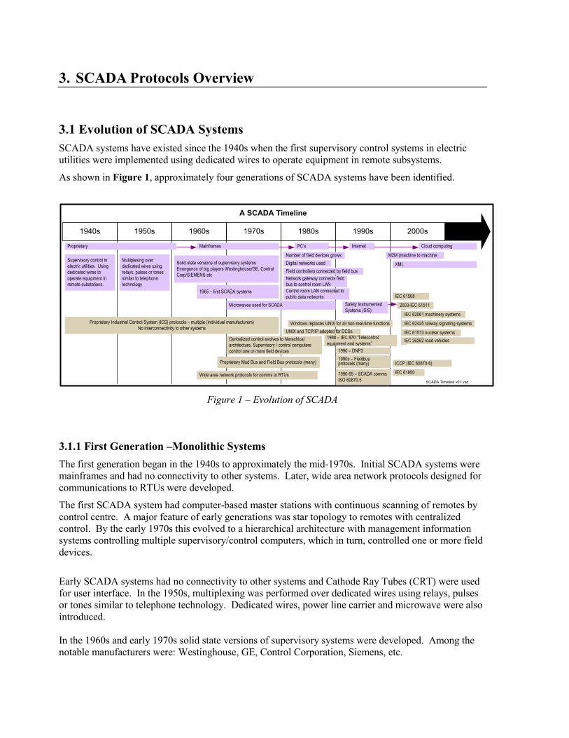
3.1 Evolution of SCADA Systems SCADA systems have existed since the 1940s when the first supervisory control systems in electric utilities were implemented using dedicated wires to operate equipment in remote subsystems.
As shown in Figure 1, approximately four generations of SCADA systems have been identified.
Figure 1 – Evolution of SCADA
3.1.1 First Generation –Monolithic Systems The first generation began in the 1940s to approximately the mid-1970s. Initial SCADA systems were mainframes and had no connectivity to other systems. Later, wide area network protocols designed for communications to RTUs were developed.
The first SCADA system had computer-based master stations with continuous scanning of remotes by control centre. A major feature of early generations was star topology to remotes with centralized control. By the early 1970s this evolved to a hierarchical architecture with management information systems controlling multiple supervisory/control computers, which in turn, controlled one or more field devices.
Early SCADA systems had no connectivity to other systems and Cathode Ray Tubes (CRT) were used for user interface. In the 1950s, multiplexing was performed over dedicated wires using relays, pulses or tones similar to telephone technology. Dedicated wires, power line carrier and microwave were also introduced. In the 1960s and early 1970s solid state versions of supervisory systems were developed. Among the notable manufacturers were: Westinghouse, GE, Control Corporation, Siemens, etc.
1940s 1950s 1960s 1970s 1980s 1990s 2000s
1990 – DNP31990s – Fieldbus protocols (many)
1990-95 – SCADA comms ISO 60870.5
Windows replaces UNIX for all non-real-time functionsUNIX and TCP/IP adopted for DCSs
Number of field devices growsDigital networks usedField controllers connected by field bus
Control room LAN connected to public data networks
Network gateway connects field bus to control room LAN
1988 – IEC 870 “Telecontrol equipment and systems”
Cloud computing
M2M (machine to machineSupervisory control in electric utilities. Using dedicated wires to operate equipment in remote substations.
Multiplexing over dedicated wires using relays, pulses or tones similar to telephone technology
Solid state versions of supervisory systemsEmergence of big players Westinghouse/GE, Control Corp/SIEMENS etc
Proprietary Industrial Control System (ICS) protocols – multiple (individual manufacturers)No interconnectivity to other systems
1965 – first SCADA systems
A SCADA Timeline
Proprietary Mod Bus and Field Bus protocols (many)
SCADA Timeline v01.vsd
Mainframes InternetPC’s
Wide area network protocols for comms to RTUs
Microwaves used for SCADA
Proprietary
Centralized control evolves to hierachical architecture. Supervisory / control computers control one or more field devices
ICCP (IEC 60870-6)
IEC 61850
XML
Safety Instrumented Systems (SIS)
2003-IEC 61511
IEC 61508
IEC 62061 machinery systems
IEC 62425 railway signaling systems
IEC 61513 nuclear systemsIEC 26262 road vehicles

12
Importantly, the initial protocols developed for SCADA were highly proprietary and had little or no interoperability.
3.1.2 Second Generation – Distributed Systems The second generation began mid-1970s, running until early 1980s and consisted of distributed processing across multiple systems on a LAN. Controllers and control room computers all connected by serial digital networks and serial digital buses. Controllers were put closer to field devices and control rooms contained an operator console and a supervisory computer.
By the early 1980s the number of field devices expands and digital networks were used extensively. Field controllers were now connected by a field bus and a network gateway typically connected the field bus to the control room LAN. As well, the control room LAN connected to public data networks. There was little to no security in SCADA systems during this time period.
Furthermore, protocols within the second generation were still mostly proprietary in nature.
3.1.3 Third Generation – Networked Systems The third generation began early 1980s and extended in time to the late -90s and the advent of the Internet. In this time period, a series of protocols was standardized for SCADA systems. UNIX and Transmission Control Protocol/Internet Protocol (TCP/IP) was adopted for DCSs and International Electrotechnical Commission (IEC) 870 “Telecontrol equipment and systems” was introduced. Windows replaced UNIX in the 90s for all non-real-time functions. Many new mod bus and field bus protocols were introduced in the 80s and 90s by multiple manufacturers but no clear standard emerged. The DNP3 protocol was defined as an open protocol for SCADA communications in the early 90s, becoming Institute of Electrical and Electronics Engineers (IEEE) 60870.5 by 1999. Also, there was a transition to Commercial off the Shelf Controllers (COTS) instead of proprietary/custom. SCADA Manufacturers in this time period began to focus on software features rather than hardware. Network connectivity with SCADA systems became near-ubiquitous among manufacturers during this time, but still many proprietary systems, particularly among the field devices.
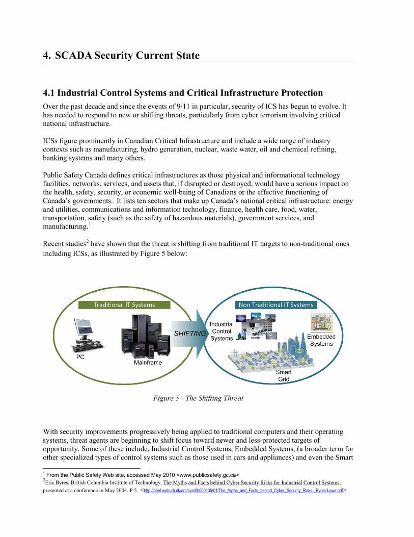
3.1.4 Fourth Generation – Internet of Things Currently and looking into the future, it is anticipated that SCADA systems will become more interconnected. Initiatives such as SMARTGRID, Cloud computing and M2M (machine to machine) will continue to drive the transformation. Protocols such as ICCP (Extensible Markup Language (XML)-based) will interconnect separate SCADA Local Area Networks (LANs) in a growing array of ‘internet of things’. The following Figure 2 summarizes the SCADA protocol landscape which has evolved over time. As well, Figure 3 shows the evolution of this trend toward great interconnectivity.
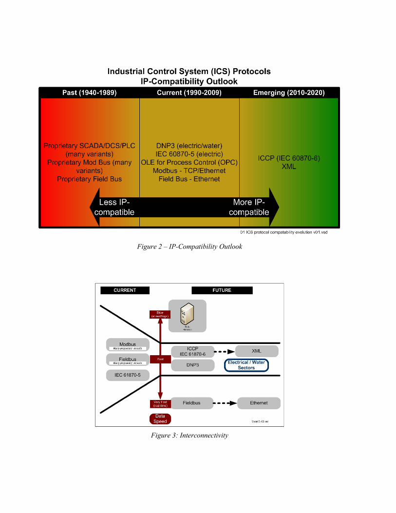
Figure 2 – IP-Compatibility Outlook
Figure 3: Interconnectivity

14
Sensors and Actuators
FieldControllers
(e.g. RTU, PLC)
Communications
ControlFacility
Field Bus
Control Data
3.2 Types of SCADA Systems Industrial Control System (ICS) is a general term encompassing two general classes of control systems:
• SCADA – Supervisory Control and Data Acquisition • DCSs – Distributed Control Systems
3.2.1 Distributed Control Systems (DCS) Usually for industrial process control plants (e.g., oil and gas, refining, chemical, pharmaceutical , some food and beverage, water and wastewater, pulp and paper, generation, mining, metals). DCSs evolved from a need to gather data and control systems on a large campus in real time on high bandwidth. Low latency data networks process control is via feedback or feed forward loops to hold conditions around a set point using custom controllers and proprietary interconnections.
3.2.3 Supervisory Control and Data Acquisition (SCADA) SCADA has evolved from distribution applications (e.g. power, natural gas pipelines, and water pipelines) and allows collection of remote data over unreliable or intermittent low-bandwidth, high-latency links.
Open loop controls with geographically separated sites, Remote Terminal Units (RTUs) were used to collect data and send it to a control centre. RTUs have evolved to have independent control capability.
DCS is typically process-state driven, whereas SCADA is event driven and central control functions usually restricted to supervisory intervention. Figure 4 shown below is an example of a Remote PLC may control flow of cooling water in a process. The Central SCADA computer may allow flow set points to be changed, alarms to be enabled, displayed or recorded. The Control loop includes PLC, but SCADA system monitors overall performance of the loop.
Figure 4: Generic Industrial Control System
4. SCADA Security Current State
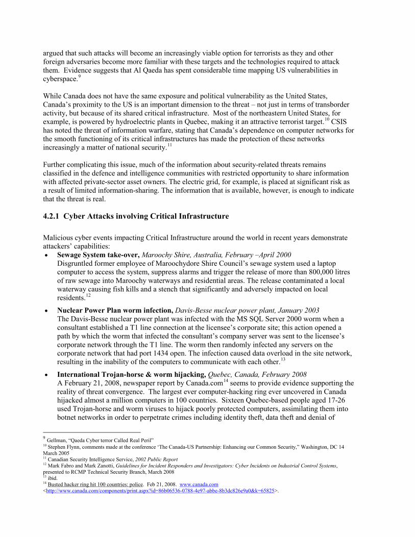
4.1 Industrial Control Systems and Critical Infrastructure Protection Over the past decade and since the events of 9/11 in particular, security of ICS has begun to evolve. It has needed to respond to new or shifting threats, particularly from cyber terrorism involving critical national infrastructure. ICSs figure prominently in Canadian Critical Infrastructure and include a wide range of industry contexts such as manufacturing, hydro generation, nuclear, waste water, oil and chemical refining, banking systems and many others. Public Safety Canada defines critical infrastructures as those physical and informational technology facilities, networks, services, and assets that, if disrupted or destroyed, would have a serious impact on the health, safety, security, or economic well-being of Canadians or the effective functioning of Canada’s governments. It lists ten sectors that make up Canada’s national critical infrastructure: energy and utilities, communications and information technology, finance, health care, food, water, transportation, safety (such as the safety of hazardous materials), government services, and manufacturing.1 Recent studies2 have shown that the threat is shifting from traditional IT targets to non-traditional ones including ICSs, as illustrated by Figure 5 below:
Figure 5 - The Shifting Threat
With security improvements progressively being applied to traditional computers and their operating systems, threat agents are beginning to shift focus toward newer and less-protected targets of opportunity. Some of these include, Industrial Control Systems, Embedded Systems, (a broader term for other specialized types of control systems such as those used in cars and appliances) and even the Smart 1 From the Public Safety Web site, accessed May 2010 <www.publicsafety.gc.ca> 2Eric Byres, British Columbia Institute of Technology, The Myths and Facts behind Cyber Security Risks for Industrial Control Systems, presented at a conference in May 2004. P.5 <http://brief.weburb.dk/archive/00000135/01/The_Myths_and_Facts_behind_Cyber_Security_Risks-_Byres-Lowe.pdf>

16
Grid (technology deployed by utilities for wireless metering and remote control of residential power systems such as heating and air conditioning.) The term ‘Industrial Control System’ refers to a collection of devices or components working together for a common process. They are controlled by a master entity that can direct, regulate, and refine the behaviour of those devices or components through observations and commands.3 ICS can variously include a range of process control systems:
• Supervisory control and data acquisition (SCADA) systems;
• Distributed control systems (DCS);
• Process Control Systems (PCS);
• Energy Management Systems (EMS); and
• Any other automated control system
4.2 Understanding the Threat to ICS ICS owners and operators face security threats beyond physical protection of assets; they must consider cyber security in the context of misuse, not just loss or unintentional physical damage of cyber-assets. Now, more than ever, security-related threats are undertaken by malicious actors who deliberately manipulate or disrupt normal operations, intending to cause damage. These particular threats pose a special set of concerns because they can arise anytime, anywhere and change and emerge without warning.4 Cyber security attacks of various kinds continue to escalate, growing in sophistication and reach every year. Even though most of the attacks have been directed at commercial targets (such as banks) and individuals (such as identity theft), there is a significant increase in the number of attacks on infrastructure such as ports, oil facilities, and the electric grid.5 Today, half of the world's critical infrastructure companies report cyber attacks, and they see the situation worsening in the future. 6 Reports by the Canadian Security Intelligence Service (CSIS) indicate that the primary threat to the physical security and safety of Canadian citizens, as well as to the country’s critical infrastructures, is international terrorism. In its first public report following 9/11, CSIS determined that Canada was at risk of being targeted directly or indirectly by Sunni Islamic terrorists.7 The Department of National Defence has echoed that the most serious, direct threat faced by Canada is terrorism.8 In the United States, the Central Intelligence Agency is also alert to the possibility of a cyber-warfare attack by terrorists. The increasing dependence of Western societies on computer systems and networks has created vulnerabilities that can be exploited. Critical infrastructures at risk of a cyber-war attack include transportation, oil and gas production and storage, water supply, emergency services, banking and finance, electrical power, and information and communications. US intelligence has 3 Mark Fabro’s definition of “Control Systems” in his Sector presentation: Process Control and SCADA: Process Control and SCADA: Protecting Industrial Systems from Cyber Attack, November 2008 4 Assante congressional testimony http://www.gpo.gov/fdsys/pkg/CHRG-111hhrg53425/html/CHRG-111hhrg53425.htm 5 ARC Advisory group - Rethinking Cyber Security: Resilient Control Systems for Securing Our Infrastructure (http://www.arcweb.com/Events/Orlando2010-ARC-World-Industry- Forum/Pages/Rethinking-Cyber-Security.aspx). 6 In the Crossfire: Critical Infrastructure in the Age of Cyberwar. Washington DC: Baker, Waterman, & Ivanov. 7 Canadian Security Intelligence Service, 2001 Public Report 8 Calder, testimony before the Standing Senate Committee on National Security and Defence
argued that such attacks will become an increasingly viable option for terrorists as they and other foreign adversaries become more familiar with these targets and the technologies required to attack them. Evidence suggests that Al Qaeda has spent considerable time mapping US vulnerabilities in cyberspace.9 While Canada does not have the same exposure and political vulnerability as the United States, Canada’s proximity to the US is an important dimension to the threat – not just in terms of transborder activity, but because of its shared critical infrastructure. Most of the northeastern United States, for example, is powered by hydroelectric plants in Quebec, making it an attractive terrorist target.10 CSIS has noted the threat of information warfare, stating that Canada’s dependence on computer networks for the smooth functioning of its critical infrastructures has made the protection of these networks increasingly a matter of national security.11 Further complicating this issue, much of the information about security-related threats remains classified in the defence and intelligence communities with restricted opportunity to share information with affected private-sector asset owners. The electric grid, for example, is placed at significant risk as a result of limited information-sharing. The information that is available, however, is enough to indicate that the threat is real.
4.2.1 Cyber Attacks involving Critical Infrastructure Malicious cyber events impacting Critical Infrastructure around the world in recent years demonstrate attackers’ capabilities: • Sewage System take-over, Maroochy Shire, Australia, February –April 2000
Disgruntled former employee of Maroochydore Shire Council’s sewage system used a laptop computer to access the system, suppress alarms and trigger the release of more than 800,000 litres of raw sewage into Maroochy waterways and residential areas. The release contaminated a local waterway causing fish kills and a stench that significantly and adversely impacted on local residents.12
• Nuclear Power Plan worm infection, Davis-Besse nuclear power plant, January 2003 The Davis-Besse nuclear power plant was infected with the MS SQL Server 2000 worm when a consultant established a T1 line connection at the licensee’s corporate site; this action opened a path by which the worm that infected the consultant’s company server was sent to the licensee’s corporate network through the T1 line. The worm then randomly infected any servers on the corporate network that had port 1434 open. The infection caused data overload in the site network, resulting in the inability of the computers to communicate with each other.13
• International Trojan-horse & worm hijacking, Quebec, Canada, February 2008 A February 21, 2008, newspaper report by Canada.com14 seems to provide evidence supporting the reality of threat convergence. The largest ever computer-hacking ring ever uncovered in Canada hijacked almost a million computers in 100 countries. Sixteen Quebec-based people aged 17-26 used Trojan-horse and worm viruses to hijack poorly protected computers, assimilating them into botnet networks in order to perpetrate crimes including identity theft, data theft and denial of
9 Gellman, “Qaeda Cyber terror Called Real Peril” 10 Stephen Flynn, comments made at the conference ‘The Canada-US Partnership: Enhancing our Common Security,” Washington, DC 14 March 2005 11 Canadian Security Intelligence Service, 2002 Public Report 12 Mark Fabro and Mark Zanotti, Guidelines for Incident Responders and Investigators: Cyber Incidents on Industrial Control Systems, presented to RCMP Technical Security Branch, March 2008 13 ibid. 14 Busted hacker ring hit 100 countries: police. Feb 21, 2008. www.canada.com <http://www.canada.com/components/print.aspx?id=86b06536-0788-4e97-abbe-8b3dc826e9a0&k=65825>.

18
service attacks. The estimated damage to governments, businesses and individuals is $45 million.
• Cyberspies penetrate the U.S. electrical grid, United States, 2009 The Wall Street Journal reports15 that, according to current and former national-security officials, international cyberspies penetrated the U.S. electrical grid and left behind software programs that could be used to disrupt the system. Cybersecurity specialists and intelligence officials believe the spies are mainly from China and Russia, due to the sophistication of the intrusions, which extended beyond the electrical grid to other critical infrastructure. They were believed to be on a mission to navigate the U.S. electrical system and its controls. No damage was done, but the officials warned that cyberspies could try to infiltrate the power grid and other key infrastructure again during a crisis or war. Senior intelligence officials explained that investigations have turned up software tools left behind, that could be used to destroy infrastructure components.
• Stuxnet work attack Iran’s nuclear facilities –Iran, June 2010
The Stuxnet worm which inflected Iranian nuclear facilities in 2010 was believed to have been created by US and Israeli Agencies. The worm specifically targets Siemens industrial control systems by subverting the Step-7 software application used to reprogram these devices. This incident was the first discovered malware that subverts ICS and the first to include a PLC rootkit.16
These are just a few examples of cyber attacks. Additionally, in the last several years17:
• Hackers have compromised: o major water utilities causing damage o dams and reservoir control systems o portions of the energy T&D capability
• Hostile mobile code and excessive packet storming have caused at least 4 nuclear facility shutdowns;
• Network failures have caused more than 1000 in-flight planes to have no communications and force;
• Major urban centers have had their traffic systems hijacked (lighting/signage);
o Hydro generation, refinery, and pipeline facilities have all experienced catastrophic damage and loss of life due to control system errors.
These examples run the spectrum from malware and mischief-making to individual criminal activity with intent to do specific damage to international terrorism – some of which relied on internal connectivity or insider knowledge
15 “Electricity Grid in U.S. Penetrated By Spies,” Wall Street Journal, 8 April, 2009. Accessed May, 2009. Available: http://online.wsj.com/article/SB123914805204099085.html 16 http://en.wikipedia.org/wiki/Stuxnet 17 Taken directly from Mark Fabro SecTor presentation: Process Control and SCADA: Process Control and SCADA: Protecting Industrial Systems from Cyber Attack, November 2008

4.2.2 The Cyber Attacker In order to understand how this threat translates into risks to control systems owners and operators, it is important to understand the actors and motivations behind cyber attacks, not just on control systems, but on digital computing in general. In his testimony before the US House Subcommittee on Emerging Threats, Cybersecurity, and Science and Technology, Seán McGurk (USDHS) described several broad types:18
• Common hackers comprise the most prevalent group of cyber attackers. They attempt to break-in or hack into computer systems or exploit flaws in software to circumvent systems security. Often the motivation is data exfiltration for financial gain. Other hackers install backdoors such as Trojans or other software such as rootkits that enable them to remotely access the system or device at a later date to perform a variety of nefarious actions. • The insider is a dangerous threat to control systems because the individual has internal knowledge to processes and components. Insiders can defeat security measures put in place even when entities follow best practices and procedures. • Cyber-terrorists or hacktivists are those who seek to disrupt Internet activity in the name of a shared ideology or personal, political, or social cause. These actors collaborate via cyberspace and work as an organized group against their targets to further their political or social agenda. Web defacements, denial of service attacks and redirects are the most common acts carried out against a target or targets.
The United States Government Accountability Office (GAO)19 has published findings which identify the emerging threat agents likely to perpetrate cyber-attacks against Critical Infrastructure, which typically use process control systems to operate a wide range of applications including hydro-electric dams, nuclear plants and manufacturing factories to municipal water purification systems (see Table 1):
Table 1Emerging Threat Agents
Critical Infrastructure Threat Agents Bot-network operators Criminal groups Foreign intelligence services Hackers Insiders Phishers Spammers Spyware/malware Authors Terrorists
18 McGurk, Seán P. “Securing the Modern Electric Grid from Physical and Cyber Attacks”. (July 21, 2009) Testimony before US House of Representatives House Committee on Homeland Security http://homeland.house.gov/SiteDocuments/20090721141651-51198.pdf 19 GAO,05-434 Department of Homeland Security faces challenges in fulfilling Cybersecurity responsibilities, May 2005, p.5. < http://www.gao.gov/new.items/d05434.pdf >.

20
The following Figure 6 summarizes a taxonomy of typical incidents for Industrial Control Systems:
Figure 6-ICS Incident Taxonomy
4.2.3 Findings from Canadian Threat Studies The Public Safety Canada Cyber Security Strategy Secretariat published a study20 in July 2007 that identified threats common to the environment of ICS and SCADA systems (Table 2). The PSC findings mirror the GAO findings from the United States.
Table 2 Findings from Canadian Threat Studies
Actor/Agent Typical Mode Motivation Commercial Competition Social networking, Open Source $ Hackers Computer Network Exploitation and Attack, Malcode,
social engineering, dumpster diving, defacement Access to computer systems
Phreakers telephone switch access Toll Fraud Terrorists Explosives, hostage, propaganda Fear and messaging Criminal Extremists Explosives Retribution Organized Crime Theft, fraud, laundering, drugs, contraband, black
marketing, prostitution, credit cards, banking $
Insider Sabotage, accounting fraud Retribution, disgruntled, personal gain Military Physical kinetic attack Destruction of enemy forces
20 Final Report. Cyber Interdependencies within Canada’s Key Infrastructure Sectors, July 6, 2007. P.94. Copies of this report can be obtained from the PSEPC Cyber Security Strategy Secretariat.

Actor/Agent Typical Mode Motivation State espionage HUMINT, SIGINT, TCHINT, ELINT, IMINT,
PSYOPS, EW Confidentiality of military and economic information
Fundamentalists (ideology) Social networking, propaganda, physical intimidation Conversion Organizational Risk aversion, inaction, red tape, fratricide Maintain control Natural /Accidental Physical Path of least resistance, affecting
independent systems along risk conductors
Importantly however, the study also identified and discussed the growing phenomenon of threat convergence. As the study points out:
“The reality is that the threat agents facing the data-interdependent critical infrastructures of 2007 have compounded agendas and common exploitation tools at their disposal. Although this does not necessarily mean those traditional threat agents have merged organizations nor have established lines communications; in cyberspace they start to look similar, act the same and tread over each other’s conventional turf. Cyber space acts as a confluence for the threat, and the threat like a collective.”21
Threats from the table above, therefore, should also be considered in a new paradigm:
Actor/Agent Typical Mode Motivation Groups interbreeding, morphing, mixing and competing for territory
Multi-source collection, blended attacks, joint operations
Multiple agendas
4.3 Current State of SCADA Security
Most SCADA systems have not been designed with security in mind and a majority of traditional device protocols have no security provisions. Instead, systems are designed with attention to functionality and liability, the result of which are inherent security vulnerabilities. Components are also designed assuming either a trusted environment (for example, isolation) or an environment where other components implement various protections.22
Process control networks that were once isolated are now being connected to corporate networks, which also creates cyber attack vulnerabilities. Additionally, increasing sophistication of threats, and the threat of insider misuse creates a challenge for unprotected or loosely secured systems. Cyber threats to control systems are still evolving and are not yet fully understood, as discussed in section 5.2.3 with the introduction of the concept of ‘threat convergence’. The potential for an intelligent attacker (or collaborating attackers) to exploit a common vulnerability that impacts many assets at once, from a distance, is one of the most disconcerting aspects of this challenge.
21 Ibid, p.94. 22 “Rethinking Cyber Security: Resilient Control Systems for Securing Our Infrastructure,” presentation at the ARC World Industry Forum: Where Industry Leaders Meet to Solve Their Most Challenging Issues, February 8-11, 2010 - Orlando, Florida. Available at: http://www.arcweb.com/Events/Orlando2010-ARC-World-Industry-Forum/Pages/Rethinking-Cyber-Security.aspx

22
4.3.1 The Nature of ICS and SCADA Makes Them Vulnerable Systems
The technical nature of ICS and SCADA systems makes them vulnerable to an array of cyber threats. ICS differ from more traditional IT systems and environments in a number of key and significant ways. The main distinctions are summarized in Table 3 below.
Industrial control systems are at the core of Canadian critical infrastructure (see chart at right) and encompass many different and diverse organizations and facilities, including: electric power, oil, water, gasoline, chemicals, manufacturing, mining, transportation, food processing, etc. The purpose of an ICS is typically to control some kind of physical process in an industrial, manufacturing or remote environment. While IT Systems use physics to manipulate and control data, ICS use data to manipulate physics (i.e. control physical processes). For example, ICS are used to generate hydro in a power station, manufacture tires in a plant, control traffic lights on a highway and regulate the flow of natural gas through a pipeline. The end user in an ICS is a computer or remote sensor. By contrast, IT systems are designed for human end-users and are usually situated in business or home environments to perform tasks such as email, spreadsheet calculations, browse the internet, populate databases and store business information. ICS typically operate in hostile or remote locations and require the process controller components to be ruggedized against failure, whereas IT components typically are centrally located in corporate server rooms and are easily accessed for service. Even Industrial Control Systems, there are important differences between different kinds of ICS. As shown in Figure 7, SCADA systems operate in near real-time conditions (e.g. hydro generation), whereas other ICS such as DCS, PCS and EMS are considered real-time (e.g. manufacturing/production). This is an important factor when decisions are made about where best to deploy a data-centric approach, discussed later in this report.
Figure 7- Differences within ICS
Industrial Control Systems are not traditionally designed or configured with security in mind, although this is gradually changing. ICS is concerned with continuous availability of services, whereas within

traditional IT environments, confidentiality of data is paramount. This is primarily because industries with ICS use these systems to generate profits from selling commodities or products to users. If the ICS systems aren’t running this immediately, this can directly impact profits the company makes and explains why the organization always wants its systems to be continuously operating and available. The hardware used in Industrial control systems, includes numerous components and protocols unique to the process control environment. Terms such as HMI, Historian, RTU, IED and PLC refer to hardware components only found in process control environments. Each of these components capture, store and process information like traditional IT systems, but how these components accomplish these actions is where the similarity ends. ICS systems also utilize unique and even proprietary protocols exclusive to the process control environment. Protocols such as ICCP, DNP3, Internet Group Management Protocol (IGMP), and Fieldbus are not found anywhere else but the ICS environment. Not surprisingly, the expertise to create and maintain process control systems is extremely specialized and is in the realm of sector-specific engineering. Much of the equipment and code developed by specific vendors for industrial control systems is proprietary and even include proprietary protocols. Due to the specialized nature of this equipment, operators regularly work closely with vendors to maintain ICS components. It is common for vendors to have a Virtual Private Network (VPN) connection to install equipment at the operator site to monitor and maintain it remotely. By extension, in the event of a cyber-incident, it is common for operator staff and engineers to interact with vendors early on, due to specialized information they possess, such as, vulnerability and configuration information. Another key distinction between Industrial Control and IT Systems is the potential impacts resulting from threats to ICS. Traditional IT systems for businesses or individuals in a home setting can experience a range of impacts due to risks, including viruses, malware, identity theft, theft of company data and other similar threats. These kinds of risks typically cause impacts ranging from annoyance and minor inconvenience to large-scale information theft or individual identity theft due to phishing attacks. By contrast, the impacts to Industrial Control Systems can range from minor impacts such as malware infections or data loss to extreme impacts including mass disruption, catastrophic events, environmental damage and death. Cyber events in an ICS environment typically occur in real-time and can result in a chain of events that alters safety parameters of industrial processes and eventually results in mass destruction, such as from explosions, overloaded electrical transmissions or fire in a manufacturing facility. In fact, many ICS environments include major industrial complexes such as hydro generation or oil refineries, which if destroyed, could take up to ten years to rebuild. IT environments undergo regular upgrades due to evolving technologies and software patching/updates. A typical IT ever greening plan will see the replacement of servers and other IT equipment approximately every 5 years. By contrast, ICS equipment has a much longer life-cycle, as much as 30-50 years and the supporting software would range over multiple generations from Windows 95 all the way up to current releases. The environment within traditional information technology and Industrial Control Systems differ in a number of ways, as, just discussed above and summarized in Table 2. As alluded to in the previous table, Industrial Control System environments are very concerned with availability of services provided by the infrastructure or ‘always being on’. This is in sharp contrast to IT environments which place an emphasis more upon confidentiality and integrity before availability. As a result, ICS environments don’t have a strong security code of practice and, instead, focus on keeping components in the infrastructure operational.

24
Another major way then that these environments differ is in regards to security and the entire approach to protecting the associated infrastructure. Users and administrators in IT environments have a good awareness of security issues such as viruses, portable code, phishing, email attachments and other related items. While this is partially due to increased sensitivity from near-daily media headlines about viruses etc. more importantly, a majority of organizations have well-developed IT security training and awareness programs for users in these environments.
Table 3 – Distinctions between Industrial Control and IT System Environments
Attribute Traditional IT Industrial Control Systems Operating environment Office / home Industrial / manufacturing / remote
Cyber security priority confidentialityintegrityavailability availabilityintegrityconfidentiality
Key hardware components CPU, hard drive, CD burner, server, modem, Ethernet, wireless card, etc.
RTU’s, HMI’s, IED, Historian, Engineering Workstation, etc.
Protocols TCP/IP, HTTP, SMTP, FTP, etc. ICCP, DNP3, Mod Bus, Field Bus, etc.
Skills to develop or operate these technologies
Common, widespread, ubiquitous, plentiful (e.g. architects, programmers, network administrators)
Very specialized by sector, type of technology and vendor.
Potential impacts due to cyber incidents
Viruses, malware, denial of service, theft of company data, cyber crimes against individuals (phishing, identity theft, fraud)
Potentially catastrophic events, mass disruption, significant environmental damage, facility/equipment damage, death
Evergreening of hardware and software
Equipment frequently replaced. Shorter lifespan, <10 years, new software technology introduced regularly
Equipment lifecycle long, typically 10+ to 50 years. Software can cover multiple generations (e.g. Win NT, 95, 98, XP, 8.1 and up). Newer equipment (10 years old or less) can connect to networks.
By contrast, ICS environments, including engineers and operators, are not generally aware of cyber security. In the event of an incident, the first action is likely to ‘get the broken part running again’ rather than to treat it as potentially suspicious activity as an event which might have originated from an external attack or malicious code infection. Within IT environments, equipment such as servers is normally locked up in server rooms requiring privileged access. As well, workstations are typically locked down with passwords, encryption and network zoning through firewalls and operating systems are restricted to privileged users. By contrast, industrial control systems are frequently housed in facilities which may be locked, but are remote and may not have resident staff onsite. ICS components such as the HMI or engineering workstation are typically left logged in. As well, a user id/password will generally allow access to all components on the SCADA LAN as opposed to limited access control and ‘need to know’ principles. Thus, if someone were to break into a remote ICS facility, they would generally have access to the key ICS systems within which are left logged on. Security testing in IT environments regularly occurs as patches and software is security tested for code-level vulnerabilities prior to deployment. By contrast industrial control systems are not designed or deployed with security in mind and the usual form of testing is for system outages, referring to the priority on reliability, performance and availability as discussed earlier. By extension, whereas in IT environments some scheduled (and unscheduled) outages are acceptable, within ICS environments the goal is to be operational 100% of the time and outages are never acceptable. Change management is commonly scheduled and performed within IT environments, but for ICS, legacy-based technology is

not really designed for modern security methods. For example, industrial control systems have limited power and are often sensitive to latency. Common IT security technical controls such as host-based intrusion prevention systems (IPS) or even anti-virus for sensor components are very difficult to implement and often interfere with ICS configurations. While common in IT environments, patch management such as scheduled and unscheduled down-times for applying security patches is not practical in ICS environments. As well, application of patches to ICS is generally slow due to being vendor-specific. Outsourcing of system maintenance is very common for IT systems but is almost never done for ICS environments. This is primarily due to the very customized and specialized nature of process control environments. For example, while there are many hydro-generating facilities throughout Canada and the United States, each one tends to be custom-designed and is also based on the geographic constraints and hydro-generating nature (i.e. wind, gas, water, nuclear etc.) of each the location. Effective audit and logging is commonly available for traditional IT systems, including being compliant for forensics methods. However, retrieval of digital evidence in process control environments is considerably more complex, due to the proprietary nature of the hardware and software. However, when software such as Windows or Linux or Unix is used, some ICS components will have logging capability. But where specialized ICS components, such as field devices, use proprietary software, the ability to extract digital information can widely vary depending upon many factors including whether data has been even recorded (often logging is turned off), whether the information has been overwritten (volatility of memory), whether the first responder must work with the sw/hw Vendors (vendors can be reluctant to discuss vulnerabilities), whether there have been post-implementation modifications to the software configuration (and has this even been documented), and many other factors. The following Table 3 below summarizes the key technical security differences between the two environments of traditional IT and Industrial Control Systems.
Table 4 – Technical Security Posture Differences between ICS and IT Systems
Attribute Traditional IT Industrial Control Systems IT Security Training & Awareness
Generally good awareness of cyber security in public and private sector
Poor to low understanding of cyber security in the industrial control environment
Physical security Server rooms and IT equipment are generally secure
Generally secure but facilities are often remote and/or unstaffed
IT security testing or audit Regularly scheduled and compliance mandated
No specific security testing normally performed except for outages
Availability Delays are typically acceptable 24/7 x 365 x forever
Time sensitive content Delays are typically acceptable Safety critical
Change management Commonly scheduled and performed Legacy based technology not suitable for modern security methods
Application of patches Consistently scheduled and performed Generally slow due to being vendor-specific
Outsourcing Common and pervasively used Rarely used
Anti-virus & mobile code protection
Common and pervasively used Not common and difficult with deployment
Logs Effective audit logging available. Most likely forensics compliant documentation available.
Where modern software used (e.g. Win, UNIX, etc.), effective audit logging available but probably not for proprietary sw/hw such as that used in remote sensors.

26
4.3.2 Common ICS Security Weaknesses Homeland Security in 2010 analyzed the cyber security vulnerabilities in Industrial Control systems based on assessments undertaken with ICS operators. The report provides extensive evidence that security vulnerabilities exploitable by cyber attackers continue to persist widely among ICS Operators. According to the report, the top three highest percentages of vulnerabilities identified in ICS product assessments are:
• Improper input validation by ICS code • Poor access controls – credential management and security configuration • Authentication weaknesses
A more granular analysis of vulnerabilities is summarized in Table 4:
Table 5 – ICS Security Weaknesses Identified by DHS
Category Vulnerability Common ICS Software/Product Security Weaknesses
Improper input validation Poor code quality Permissions, privileges, and access controls Improper authentication Insufficient verification of data authenticity Cryptographic issues Credentials management ICS software security configuration and maintenance (Development)
Common ICS Configuration Weaknesses Permissions, privileges, and access controls Improper authentication Credentials management ICS security configuration and maintenance Planning/policy/procedures Audit and accountability
Common ICS Network Security Weaknesses Common ICS network design weaknesses Weak firewall rules ICS network component configuration (implementation) vulnerabilities Audit and accountability
In his 2008 paper, “Assuring Industrial Control System (ICS) Cyber Security,” Joe Weiss makes an important note that is not always clarified in current ICS cyber security discussions: it is often, but mistakenly, assumed that a cyber security incident is always a premeditated, targeted attack. Unintentional compromises of confidentiality, integrity, or availability of an information system, are more prevalent and can have severe consequences. Protecting ICS from these unintentional compromises also protects them from intentional compromise and outside threat.23 The current doctrine for securing SCADA in North America is to focus on IP protocols rather than serial communications (including DNP3, ICCP, Mod Bus and others) and the equipment using them. As reported recently in the New York Times24:
23 Joe Weiss. “Assuring Industrial Control System (ICS) Cyber Security,” 25 August 2008. 24 http://bits.blogs.nytimes.com/2013/10/18/electrical-grid-called-vulnerable-to-power-shutdown/?hpw&_r=1

“Even more troubling… is that most DNP3 communications aren’t regulated. The original version of DNP3 worked on serial communications — a way of transmitting data usually found in things like coaxial cables — and is still widely deployed in large systems, particularly substations around the country. But current cybersecurity regulations, governed by the North American Electric Reliability Corporation’s (N.E.R.C.) Critical Infrastructure Protection Committee (C.I.P.C.) are focused on Internet Protocols, or I.P. protocols, and specifically exclude serial communications and the equipment that uses them from meeting any security requirements.”
With the wide array of proprietary vendors producing SCADA and ICS equipment, it is not surprising that NERC has focused on the network and not the SCADA components themselves. Due to the unique and proprietary nature of the protocols typically used in ICS, the success of securing ICS requires the cooperation of ICS owners, operators, and the ICS component manufacturers themselves. As the following Figure 8 shows, IP compatibility in SCADA/ICS systems and protocols decreases when moving from the Control components to the Controllers and Field Devices.
Figure 8-SCADA Component Protocol Compatibility with IP
Traditional IM/IT data
Internet Protocol (IP) based
SCADA Component Protocol Compatibility with IP
More IP-compatible
Less IP- compatible(Proprietary
signals)
Control(HMI, EW, Historian)
Field Devices(PLC, IED, etc.)
Controllers(RTU)
02 Component IP compatibility view v01.vsd

28
5. Advance Protection Techniques - Data Centric Security
Overview – IM Systems
A network environment that is protected by the Data Centric security overlay will have Data Centric enabled application proxies positioned between the user workstation and the back end data service that is serving data to the user’s application. In that location, the application proxies are able to monitor the information request/response cycle. By intercepting the information flow, Data Centric can be invoked to mitigate access to data and only release information when the request is compliant with the security policy. The software components that intercept information requests are part of the application Policy Enforcement Point (PEP) architecture in that they:
• Interpret the information that is being requested;
• Formulate the information request in terms of a policy decision request;
• Send the policy request to the Authorization Service;
• Respond to the decision that has been returned in a policy decision response
• Perform any needed transformations on the data; and
• Audit the actions that were taken in the course of processing this information request.
Since the communication protocols and data formats vary depending on the type of application that is to be protected, the proxy portion of the application PEP will vary in its implementation. However, the general application proxy architecture for intercepting data, the leveraging of the defined core security services and information protection logic that defines how Data Centric processes data requests, leads to the complete picture of the Data Centric security architecture.
The following sub-sections describe key technical concepts that will be used to address the secure operation of the collapsed enclaves in order to support convergence. These concepts are deemed essential to providing the requisite data protection including operator “need-to-know” access.

Figure 9- Data Centric Security Services
The above diagram provides a detailed interpretation of the Data Centric processing steps involved in an attempt to retrieve a file from a Data Centric protected file store.
1. Over an authenticated session, the Data Centric user submits a request to retrieve the file to the Data Centric file sharing PEP using the file management tools that are present in the target environment (e.g. Windows File Sharing).
2. The Data Centric File Sharing PEP retrieves a copy of the file, in encrypted form, to the PEP for local processing. Any temporary or working files are removed and the associated memory locations zeroized at the end of the transition processing cycle.
3. The Data Centric labelling service, co-located with the File Sharing PEP with access to the local copy of the encrypted file, is called to extract the security label on the target file.
4. With the identity of the user, the security attributes of the file and the requested action on the file now known, the PEP calls the Authorization Service to determine if the transaction is permitted as per the domain security policy.
5. The Authorization Service calls upon the identity service to retrieve security attributes of the user, including the user’s membership in communities of interest. This information is returned to the Authorization Service which then evaluates the request against the policy and returns a decision to the PEP.
6. Where the transaction is permitted, the PEP calls upon the Cryptographic Transformation Service to decrypt the file prior to delivery.
7. The CTS calls upon the Key Management Service using the token that is stored with the data asset to retrieve the key that was used to protect the file as it was originally protected by Data Centric.

30
8. After performing the decryption process on the data asset, the file is ready to be delivered to the end user. However, prior to delivery, an audit record of the transaction is submitted, along the Audit Message Bus, to the Trusted Audit Store and, subsequently, to the Audit Store.
9. The originally requested file is then delivered to the end user.
Unlike the Data Centric security services, which are exclusively connected to the Data Centric security or audit message bus, the Data Centric application services must maintain multiple independent communication channels:
1. On the DATA network, the application proxy communication channel that monitors the traffic between the source and target of the information request (i.e. the user and the data); and
2. On the Data Centric security message bus, the PEP is able to leverage the Data Centric security services for data mediation and protection. If the chosen deployment architecture calls for security and audit messages to be hosted on separate networks, a third connection is needed to connect the PEP to the Audit Secure Message Bus.
Using this generalized architecture, the Data Centric security overlay is able to provide information protection for a wide range of applications as defined below.
File Sharing: Data Centric intercepts file access attempts, including directory listings and operations on individual files. The Data Centric Application file sharing service will make policy decisions based upon the identity of the user requesting access to the file, the label on the targeted file, and the operation that is being attempted.
Instant Messaging: Data Centric intercepts the creation and joining of chat rooms and only allows those rooms to which a user has a policy right to create or access, respectively. Messages sent via the IM server remain protected while awaiting delivery and are only accessible to users that are leveraging the Data Centric security overlay. Chat room history is similarly stored in encrypted form. Individual messages can be sent in a sub-channel within the chat room, that is encrypted with a unique key and restricted to a smaller community of users within the chat room
Email: Data Centric intercepts email messages in transit and enforces the security policy to ensure that the originator has the policy right to send the message and its attachments. Data Centric will, for each recipient, ensure that the message and its attachments can be received. Email messages will not be delivered to recipients for whom access to the information will be a policy violation. Messages are stored in encrypted form while awaiting delivery.
Web Services: Data Centric protects web services by gating access to the web interface, only allowing users with a policy right to access the service to submit web requests via that interface.
5.1 Data Centric Security vs Network Centric
Traditional security solutions rely on the network to provide a number of security safeguards for an organization. These safeguards such as Firewalls, authentication, Intrusion Detection Systems (IDS), Anti-Virus Protection (AVP) have been deployed to prevent the breach of the network through, Detection, Response, Resolve, and Monitor activities. Despite the number of security safeguards, incidents continue to occur resulting in data leakage and the exfiltration of sensitive information.

Data centric security compliments the network security through the application of security (labelling, encryption and mediation) to the individual data objects or data within a network. The protection of data objects at the data level allows for a breach to occur at the network level yet the loss of data (confidentiality, integrity, availability) will have little or no effect because each object is protected individually.
The application of a data centric approach for SCADA systems will allow for the protection of control systems data and event/historian data in the event that the network has been breached and malware is present.
5.2 Data Centric Security – SCADA Systems
5.2.1 Overview
The examination of advanced protection techniques and their applicability to SCADA systems and in particular those used for utilities is the purpose of this technology assessment report. The power industry has advanced the use of SCADA systems within its sector and includes a range of components and systems that may be analyzed for the suitability of data centric protection techniques. When applied to Information Management/Information Technology (IM/IT) systems, data centric best provides safeguarding across the two of the three typical security attributes, Confidentiality and Integrity but to a lesser degree, Availability (CIA). SCADA control system must focus on Integrity and Availability of the flow of control data to RTUs and PLC in the field. The flow of information in reverse, data points which indicate, status, measurement of process values and historian values maybe viewed with the traditional IM/IT the perspective and application of section 5 is direct.
There are three dominate protocols that the power industry uses to communicate and control, Inter-Control Centre Communications Protocol (ICCP), ModBus and DNP3. The details of these control protocols are examined in the following sections.
5.2.2 ICCP ICCP, known in Europe as Tele-control Application Service Element (TASE2) (Figure10), is a standardized and widely adopted communications protocol (IEC 60870-6) for information exchange. The protocol facilitates seamless exchange of time-critical data over local and wide area networks and the integration of instrumentation and control into the corporate wide information and data processing in any application domain including utilities, manufacturing, process control and especially electric utility control centres. In North America, ICCP networks are widely used to tie together groups of utility companies typically a regional system operator with transmission utilities, distribution utilities and generators. Regional operators may also be connected together to co-ordinate import and export of power between regions across major inter-ties.

32
Figure 10 ICCP
ICCP allows the exchange of real time and historical power system information including status and control data, measured values, scheduling data, energy accounting data and operator messages. Basic ICCP functionality is specified as “Conformance Blocks” listed below. The objects that are used to convey the data are defined in various parts of IEC 60870-6. Block Description Data Examples:
1. Periodic System Data – Status points, analogue points, quality flags, time stamp, change of value counter, protection events. Association objects to control ICCP sessions;
2. Extended Data Set Condition Monitoring – Provides report by exception capability for the data types that block 1 is able to transfer periodically;
3. Block Data Transfer – Provides a means transferring Block 1 and Block 2 data types as block transfers instead of point by point. In some situations this may reduce bandwidth requirements;
4. Information Messages – Simple text and binary files. 5. Device Control: -- Device control requests: on/off, trip/close, raise/lower etc. and
digital setpoints. Includes mechanisms for interlocked controls and select-before operate;
6. Program Control – Allows an ICCP client to remote control programs executing on an ICCP server;
7. Event Reporting – Extended reporting to a client of error conditions and device state changes at a server;
8. Additional User Objects – Scheduling, accounting, outage and plant information. 9. Time Series Data – Allows a client to request a report from a server of historical time
series data between a start and end date.

ICCP is in the upper sublayer of Layer 7 of the Open Systems Interconnection (OSI) stack and is just one of the elements in the standard 7 layer OSI model. As such, any physical interfaces, transport, and network services that fit this model are supported, with TCP/IP over Ethernet, typically being the most common. It uses Manufacturing Messaging Specification (MMS) as the underlying messaging service. MMS is used because it is the only public (ISO standard) protocol that has a proven implementation track record that can easily support the complex naming and service models inherent in IEC61850.
Figure 11- IEC 60870 Protocol
ICCP is based on client / server principles. Data transfers result from a request from a control centre (client) to another control centre (server). Control centers may be both clients and servers. ICCP may operate over a single point-to-point link between two control centers; however, the more general case is for many control centers and a routed wide area network. The logical connections or “associations” between control centers are completely general. A client may establish associations with more than one server and a client may establish more than one association with the same server. Multiple associations with same server can be established at different levels of quality of service so that high priority real time data is not delayed by lower priority or non-real time data transfers.
5.2.3 Modbus Modbus is a serial communications protocol, shown in Figure 12, originally developed by Schneider Electric in 1979 to be used in conjunction with its Programmable Logic Controllers (PLC)s. It has since evolved into a standard communication protocol, commonly used for connecting industrial electronic devices.

34
Figure 12 ModBus
The Modbus protocol follows a master/slave architecture where a master will request data from the slave. The master can also ask the slave to perform some action. The master initiates a process by sending a function code that represents the type of transaction to perform. The transaction performed by the Modbus protocol defines the process a controller uses to request access to another device, how it will respond to requests from other devices, and how errors will be detected and reported. The Modbus protocol establishes a common format for the layout and contents of message fields. During communications on a Modbus network, shown in Figure 13, the protocol determines how each controller will know its device address, recognize a message addressed to it, determine the kind of action to be taken, and extract any data or other information contained in the message. Controllers communicate using a master/slave technique, Figure 14, where only one device, the master, can initiate transactions or queries. The other devices, slaves, respond by supplying the requested data to the master or by taking the action requested in the query. Typical master devices include host processors and programming panels. Typical slaves include programmable controllers.
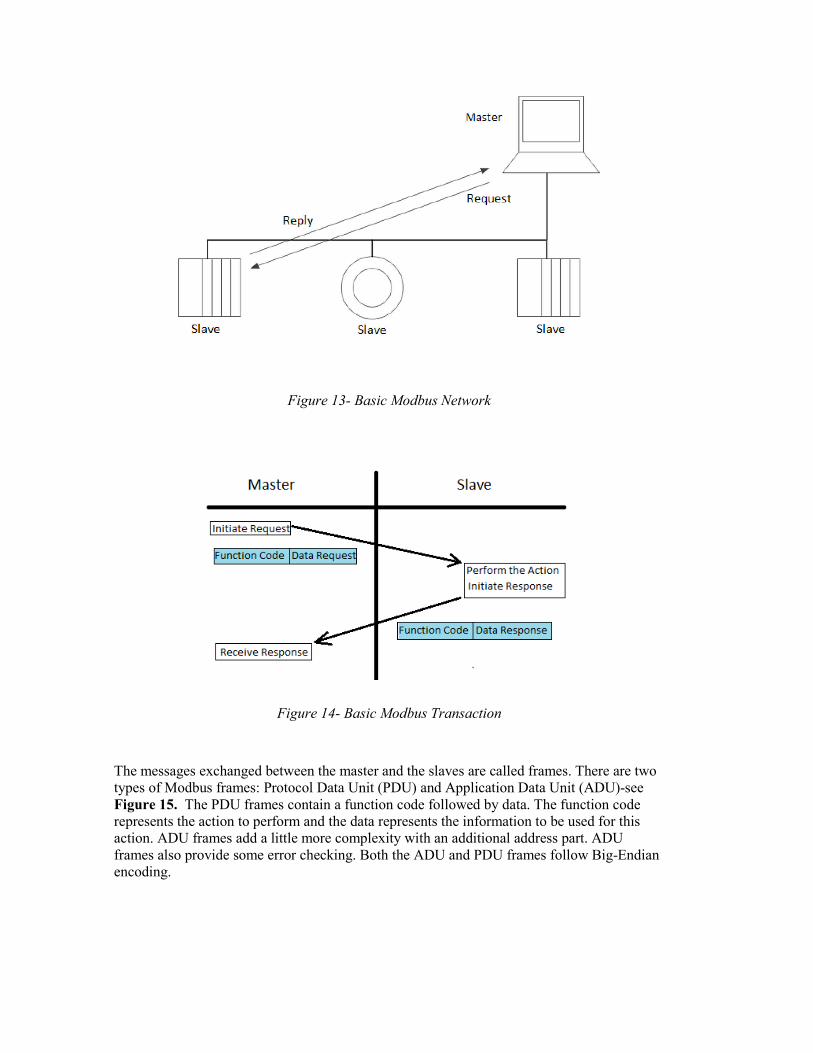
Figure 13- Basic Modbus Network
Figure 14- Basic Modbus Transaction
The messages exchanged between the master and the slaves are called frames. There are two types of Modbus frames: Protocol Data Unit (PDU) and Application Data Unit (ADU)-see Figure 15. The PDU frames contain a function code followed by data. The function code represents the action to perform and the data represents the information to be used for this action. ADU frames add a little more complexity with an additional address part. ADU frames also provide some error checking. Both the ADU and PDU frames follow Big-Endian encoding.

36
Figure 15- Modbus Frame
Modbus transactions always perform a set of actions by reading or writing to a set of four data types. Table 6 describes the four data formats used by the Modbus application layer.
Table 6 – Modbus Data Types
Primary Tables Object Type Type of
Discrete Input Single bit Read-Only
Coils Single bit Read-Write
Input Registers 16-bit word Read-Only
Holding Registers 16-bit word Read-Write
The Discrete Inputs represent a single bit (Boolean) which can only be read. In other words, the master can only perform a read action on the discrete inputs. The same holds for the Input Registers. The master can only read the slave’s Input Registers. The difference between the Discrete Inputs and the Input Registers is that the Input Registers represent 16 bits while the Discrete Inputs are only a single bit. The Coils also represent a Boolean data type which can be read and written to by the master. The Holding Registers represent a 16 bit word that can be read and written to.

Figure 16- Modbus Transaction with Data Types
Figure 17- Modbus Message
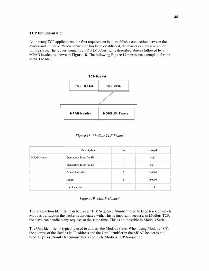
38
TCP Implementation As in many TCP applications, the first requirement is to establish a connection between the master and the slave. When connection has been established, the master can build a request for the slave. The request contains a PDU (Modbus frame described above) followed by a MPAB header, as shown in Figure 18. The following Figure 19 represents a template for the MPAB header.
Figure 18- Modbus TCP Frame1
Description Size Example
MBAP Header Transaction Identifier Hi 1 0x15
Transaction Identifier Lo 1 0x01
Protocol Identifier 2 0x0000
Length 2 0x0006
Unit Identifier 1 0xFF
Figure 19- MBAP Header1
The Transaction Identifier can be like a “TCP Sequence Number” used to keep track of which Modbus transaction the packet is associated with. This is important because, in Modbus TCP, the slave can handle many requests at the same time. This is not possible in Modbus Serial. The Unit Identifier is typically used to address the Modbus slave. When using Modbus TCP, the address of the slave is its IP address and the Unit Identifier in the MBAP header is not used. Figures 15and 16 demonstrates a complete Modbus TCP transaction.

5.2.4 DNP3 The Distributed Network Protocol (DNP3), shown in Figure 20, was introduced in 1993 by GE-Harris Canada and is designed to allow reliable communications in adverse environments that electric utility automation systems are subjected to; being specifically designed to overcome distortion induced by factors such as electromagnetic interference, aging components and poor transmission media. It is commonly used in electric and water utilities but not in other industries.
Figure 20 DNP3
It is primarily used for communications between a master station and RTUs or IEDs. In particular, it was developed for communications between various types of SCADA systems, where it is used by SCADA Master Stations, Remote Terminal Units (RTUs) and Intelligent Electronic Devices (IEDs). The DNP3 protocol has significant features that make it more robust, efficient, and interoperable than Modbus, but is of somewhat higher complexity. DNP3 message data is always comprised of one or more pairs of object header plus data object. A header specifies details about the object, e.g. width (in bits) of a counter, name of a file, etc.
It includes the following types of objects:
◦ Binary input objects ◦ Binary output objects ◦ Counter objects ◦ Analog input objects ◦ Analog output objects ◦ Time objects ◦ Class objects ◦ File objects

40
◦ Device objects ◦ Application objects ◦ Alternate numeric objects
Figure 21- DNP3 Message Data
DNP3 as shown in Figure 21 specifies a layer 2 protocol in terms of the OSI Model. It provides multiplexing, data fragmentation, error checking, link control, prioritization, and layer 2 addressing services for user data. It also defines a Transport function (somewhat similar to the function of layer 4) and an Application Layer (layer 7) that defines functions and generic data types suitable for common SCADA applications.
Model 44 v01.vsd
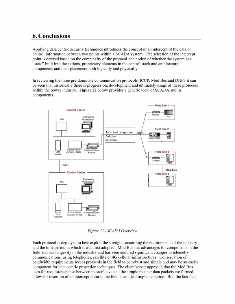
6. Conclusions
Applying data centric security techniques introduces the concept of an intercept of the data or control information between two points within a SCADA system. The selection of the intercept point is derived based on the complexity of the protocol, the notion of whether the system has “state” built into the actions, proprietary elements in the control stack and architectural components and their placement both logically and physically.
In reviewing the three pre-dominate communication protocols, ICCP, Mod Bus and DNP3 it can be seen that historically there is progression, development and ultimately usage of these protocols within the power industry. Figure 22 below provides a generic view of SCADA and its components.
Figure 22- SCADA Overview
Each protocol is deployed to best exploit the strengths according the requirements of the industry and the time period in which it was first adopted. Mod Bus has advantages for components in the field and has longevity in the industry and has seen endured significant changes in telemetry communications, using telephones, satellite or 4G cellular infrastructures. Conservation of bandwidth requirements forces protocols in the field to be robust and simple and may be an easier component for data centric protection techniques. The client/server approach that the Mod Bus uses for request/response between master/slave and the simple manner data packets are formed allow for insertion of an intercept point in the field is an ideal implementation. But, the fact that

42
mediation and protection occurs at the field level leads to a multitude of scenarios. Understanding the boundary and checkpoint faults would be extensive and difficult to model and therefore mediate.
As supervisory control and the use of DNP3 especially is considered, control elements may be simpler from a conceptual point of view, but the actual implementation of the protocol may require vendor specific knowledge to understand all aspects of the control stack as shown in Figure 20.
The first three layers of the DNP3 protocol over IP are: application, DNP pseudo-transport and DNP Data Link which are mapped into the TCP/IP communication stack. If the mapping is proprietary from the application through the second and third, the intercept can receive and re-transmit, but with limited knowledge as to the flow of control information, it will be challenging to effectively apply safeguard criteria to the control data. As DNP3 is very chatty with small packets, “state” information in transition may be required to gather enough information so as select the correct control points. This is especially challenging as timing requirements must be respected with the protocol. Access to vendor specific implementation information would be required to fully understand the model and assess viability for determining values that are out of bound or rate of change that exceed thresholds.
Figure 23- DNP3 control stack
ICCP protocol is designed to allow communication between utility control centres and if reviewed at the highest level in the chain of communication events, would offer the most flexibility, with the least investment of effort if interception was performed at the appropriate point. Figure 24 shown below details a typical sequence of communication events that allow a separate control centre to request action within another control centre.
Model 44 v01.vsd

Figure 24 ICCP Communications Overview
If this chain of communication events is examined it will be seen that there are a number of components that will interact to perform the requested actions (Figure 25). The operator console that initiates the control sequence will interact with the Application Program Interface (API) and from software point of view will call up the object models (Figure 26) in support of the required component blocks.
Figure 25 ICCP Overview

44
Figure 26 Object Model ICCP
Conformance blocks specify services, protocols and associated data objects required to implement a function or set of functions that a utility might wish to implement.
1. Periodic System Data: Status points, analogue points, quality flags, time stamp, change of value counter, protection events. Association object to control ICCP sessions.
2. Extended Data Set Condition Monitoring: Provides report by exception capability for the data types that block 1 is able to transfer periodically.
3. Block Data Transfer: Provides a means transferring Block 1 and Block 2 data types as block transfers instead of point by point. In some situations this may reduce bandwidth requirements.
4. Information Messages: Simple text and binary files.
5. Device Control: Device control requests: on/off, trip/close, raise/lower etc. and digital set points. Includes mechanisms for interlocked controls and select-before operate.
6. Program Control: Allows an ICCP client to remote control programs executing on an ICCP server.

7. Event Reporting: Extended reporting to a client of error conditions and device state changes at a server.
8. Additional User Objects: Scheduling, accounting, outage and plant information.
9. Time Series Data: Allows a client to request a report from a server of historical time series data between a start and end date.
When considering how to implement an intercept point for ICCP working at the conformance block level, it would be required to compartmentalize the actions and build a reference monitor so that policy could be applied to the transactions. The messaging system for ICCP is MMS which is open but complex. It allows for an MMS intercept to mediate the flow messages.
A better approach to deconstructing could be achievable due to clarity on structure and events if XML over HTTP is in use by the utility. This direction is very compatible for intercept technology and lends itself fully to mediate and policy control for elements within for example dispatch and query transaction sets. The adoption of XML is a newer variant in the industry, but could be promising for advance protection techniques.
Table 7 below summarizes the various protocols in use by the industry and their suitability to be used to apply data centric protection direction. Impact on Operations – Real-time protocols is much more difficult than near-real time protocols to implement
Table 7 - Comparison of ICS Protocols and Ease of Implementation of Data Centric Approach
Protocol
Assessment of Individual Protocol Attributes Impact on Operations: Near Real-Time (NRT) or Real-Time (RT)
Protocol Openness: Open Standard (O) or Proprietary (P)
Relative Implementation Complexity: Simple (S) or Complex (C)
Total
ICCP NRT O S and C25
Mod Bus RT O S
DNP3 RT P C
25 If MMS is used it is complex, XML with HTTP is simple

46
7. Recommendations
The implementation and adoption of any of the three prevailing protocols within the power utility industry will advance the application of a data centric security protection technique for industrial control systems. ICCP implementation has the advantage of sitting near the top of the communication event chain and with the industry adopting a XML approach it would lend itself ideally to a data centric mediation and protection approach. ModBus has the advantage of simplicity and granularity from the protection point of view but distribution and breadth of control can prove to obstacles, through the volume of control points, management components and policy development.
To further advance this area of study it would be necessary to examine each the protocols in a simulated network environment so as to better understand the industry and analyze protocols and the flow of simulated control data. Recommendations for further work in this area are centered on prioritization of protocols for review, which are ICCP, ModBus and DNP3, in that order.
Examination of the approaches for the intercept as presented in chapter 6 is important for the scope. However, investigation of what each protocol presents and the “state model” for protocol and the application of a reference model must be thoroughly examined. Preparation of the reference model, mediation techniques and integration of these elements in a real-time system will provide options for development and overall adoption within the industry. Finally, an overarching reference model that could incorporate data interception techniques, but include an integration of all three protocols may offer the most comprehensive solution.

8. Bibliography
1. Macauley, T. And B. Singer, Cyber security for Industrial Control Systems, CRC Press, 2012.
2. Stouffer, K., J. Falco, K. Scarfone, Guide to Industrial Control Systems (ICS) Security, NIST Special Publication 800-82, Revision 1, U.S Department of Commerce, May 2013.
3. Clarke, G., D. Reynders and E. Wright, Practical Modern SCADA Protocols – DNP3, IEC 60870-5 and Related Systems, Elsevier, 2004.
4. Fabro, Mark, Process Control and SCADA: Protecting Industrial Systems from Cyber Attack, SecTor Toronto: Lofty Perch Inc., November 2007.
References for Footnotes [1] From the Public Safety Web site, accessed May 2010 www.publicsafety.gc.ca
[2] Eric Byres, British Columbia Institute of Technology, The Myths and Facts behind Cyber Security Risks for Industrial Control Systems, presented at a conference in May 2004. P.5 <http://brief.weburb.dk/archive/00000135/01/The_Myths_and_Facts_behind_Cyber_Security_Risks-_Byres-Lowe.pdf>
[3] Mark Fabro’s definition of “Control Systems” in his Sector presentation: Process Control and SCADA: Process Control and SCADA: Protecting Industrial Systems from Cyber Attack, November 2008
[4] Assante congressional testimonyhttp://www.gpo.gov/fdsys/pkg/CHRG-111hhrg53425/html/CHRG-111hhrg53425.htm, accessed November 2014
[5] ARC Advisory group - Rethinking Cyber Security: Resilient Control Systems for Securing Our Infrastructure(http://www.arcweb.com/Events/Orlando2010-ARC-World-Industry- Forum/Pages/Rethinking-Cyber-Security.aspx).
[6] In the Crossfire: Critical Infrastructure in the Age of Cyberwar. Washington DC: Baker, Waterman, & Ivanov. http://www.mcafee.com/us/resources/reports/rp-in-crossfire-critical-infrastructure-cyber-war.pdf
[7] Canadian Security Intelligence Service, 2001 Public Report http://www.pco-bcp.gc.ca/docs/information/publications/aarchives/csis-scrs/pdf/si-eng.pdf
[8] Calder, testimony before the Standing Senate Committee on National Security and Defence http://www.parl.gc.ca/Content/SEN/Committee/371/defe/rep/rep08sep02-e.htm
[9] Gellman, “Qaeda Cyber terror Called Real Peril”
[10] Stephen Flynn, comments made at the conference ‘The Canada-US Partnership: Enhancing our Common Security,” Washington, DC 14 March 2005

48
[11] Canadian Security Intelligence Service, 2002 Public Report
[12] Mark Fabro and Mark Zanotti, Guidelines for Incident Responders and Investigators: Cyber Incidents on Industrial Control Systems, presented to RCMP Technical Security Branch, March 2008
[13] ibid.
[14] Busted hacker ring hit 100 countries: police. Feb 21, 2008. www.canada.com <http://www.canada.com/components/print.aspx?id=86b06536-0788-4e97-abbe-8b3dc826e9a0&k=65825>.
[15] “Electricity Grid in U.S. Penetrated By Spies,” Wall Street Journal, 8 April, 2009. Accessed May, 2009. Available: http://online.wsj.com/article/SB123914805204099085.html
[16] http://en.wikipedia.org/wiki/Stuxnet
[17] Taken directly from Mark Fabro SecTor presentation: Process Control and SCADA: Process Control and SCADA:
[18] Protecting Industrial Systems from Cyber Attack, November 2008
[19] McGurk, Seán P. “Securing the Modern Electric Grid from Physical and Cyber Attacks”. (July 21, 2009) Testimony before US House of Representatives House Committee on Homeland Security http://homeland.house.gov/SiteDocuments/20090721141651-51198.pdf
[20] GAO,05-434 Department of Homeland Security faces challenges in fulfilling Cybersecurity responsibilities, May 2005, p.5. < http://www.gao.gov/new.items/d05434.pdf >.
[21] Final Report. Cyber Interdependencies within Canada’s Key Infrastructure Sectors, July 6, 2007. P.94. Copies of this report can be obtained from the PSEPC Cyber Security Strategy Secretariat.
[22] Ibid, p.94.
[23] “Rethinking Cyber Security: Resilient Control Systems for Securing Our Infrastructure,” presentation at the ARC World Industry Forum: Where Industry Leaders Meet to Solve Their Most Challenging Issues, February 8-11, 2010 - Orlando, Florida. Available at: http://www.arcweb.com/Events/Orlando2010-ARC-World-Industry-Forum/Pages/Rethinking-Cyber-Security.aspx
[24] Joe Weiss. “Assuring Industrial Control System (ICS) Cyber Security,” 25 August 2008.
[25] http://bits.blogs.nytimes.com/2013/10/18/electrical-grid-called-vulnerable-to-power-shutdown/?hpw&_r=1
