data and computer communications - dr. bhargavi … · data and computer communications ... •ie....
TRANSCRIPT

Data and Computer Communications
Dr. Bhargavi Goswami,HOD – CS, Associate Professor,
Garden City College,Bangalore.
Chapter 4 –Transmission Media
Transmission Media
Communication channels in the animal world include
touch, sound, sight, and scent. Electric eels even use
electric pulses. Ravens also are very expressive. By a
combination voice, patterns of feather erection and
body posture ravens communicate so clearly that an
experienced observer can identify anger, affection,
hunger, curiosity, playfulness, fright, boldness, and
depression. —Mind of the Raven, Bernd Heinrich
Overview
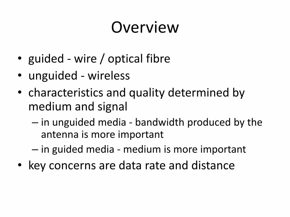
• guided - wire / optical fibre
• unguided - wireless
• characteristics and quality determined by medium and signal– in unguided media - bandwidth produced by the
antenna is more important
– in guided media - medium is more important
• key concerns are data rate and distance
Design Factors
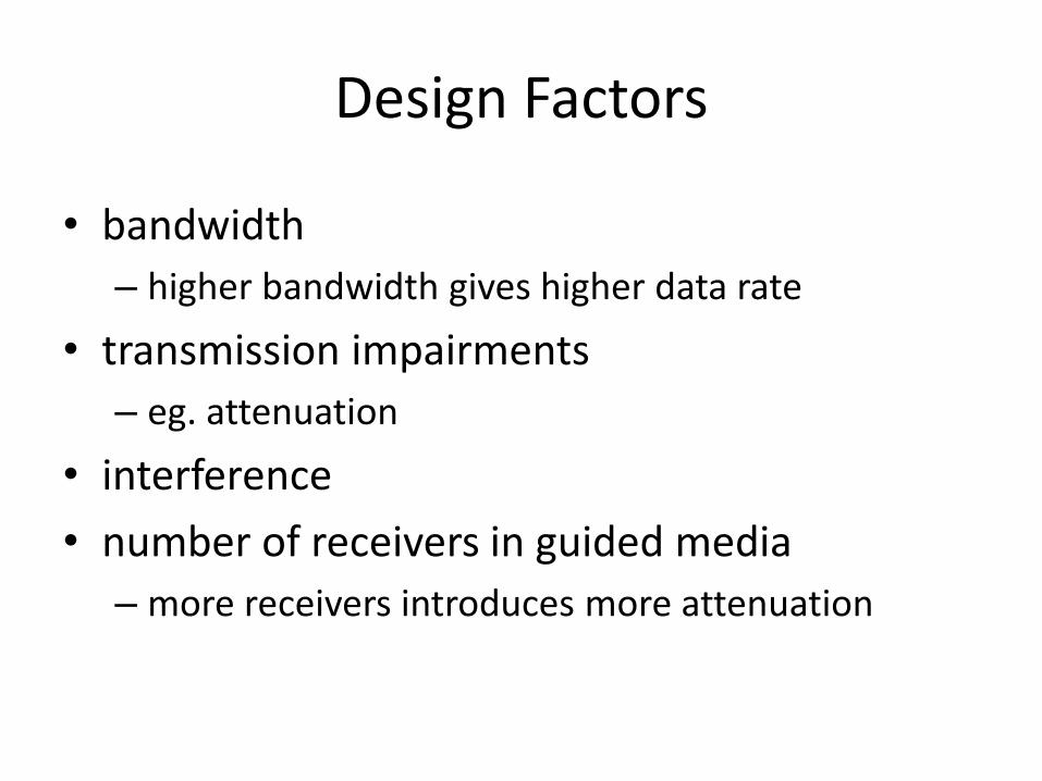
• bandwidth
– higher bandwidth gives higher data rate
• transmission impairments
– eg. attenuation
• interference
• number of receivers in guided media
– more receivers introduces more attenuation
Electromagnetic Spectrum
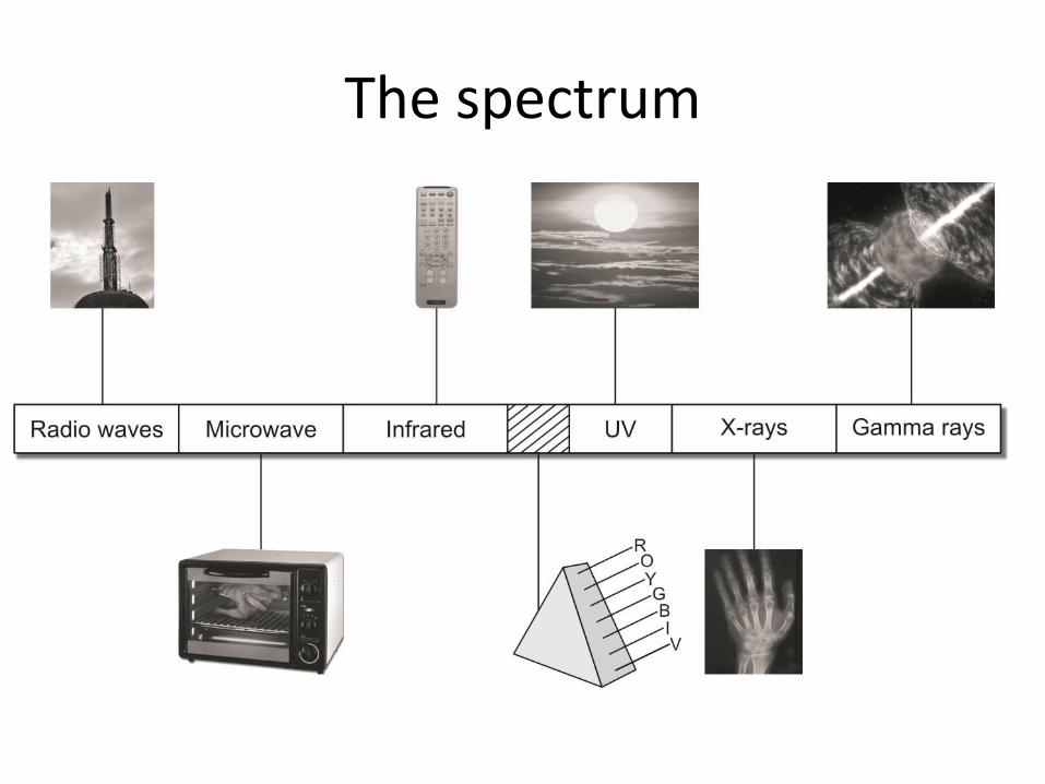
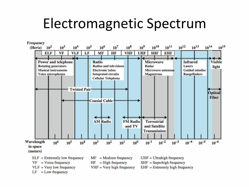
The spectrum
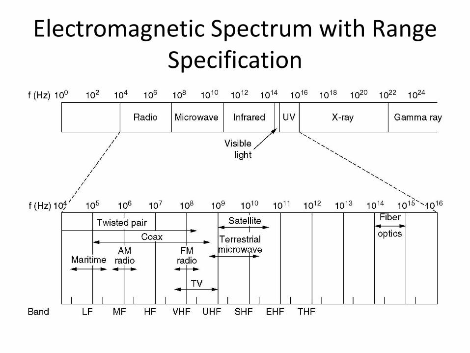
Electromagnetic Spectrum with Range Specification
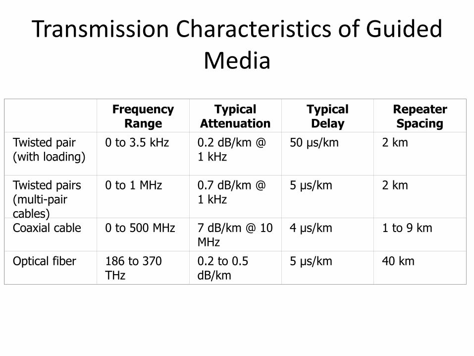
Transmission Characteristics of Guided Media
Frequency Range
Typical Attenuation
Typical Delay
Repeater Spacing
Twisted pair (with loading)
0 to 3.5 kHz 0.2 dB/km @ 1 kHz
50 µs/km 2 km
Twisted pairs (multi-pair cables)
0 to 1 MHz 0.7 dB/km @ 1 kHz
5 µs/km 2 km
Coaxial cable 0 to 500 MHz 7 dB/km @ 10 MHz
4 µs/km 1 to 9 km
Optical fiber 186 to 370 THz
0.2 to 0.5 dB/km
5 µs/km 40 km
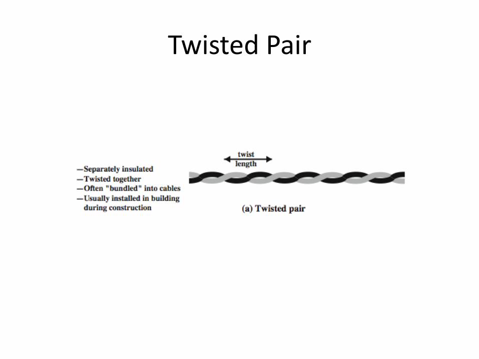
Twisted Pair
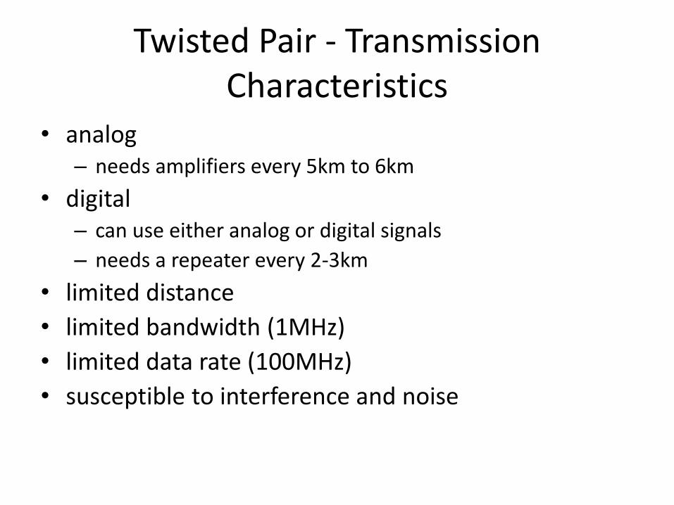
Twisted Pair - Transmission Characteristics
• analog – needs amplifiers every 5km to 6km
• digital– can use either analog or digital signals
– needs a repeater every 2-3km
• limited distance
• limited bandwidth (1MHz)
• limited data rate (100MHz)
• susceptible to interference and noise
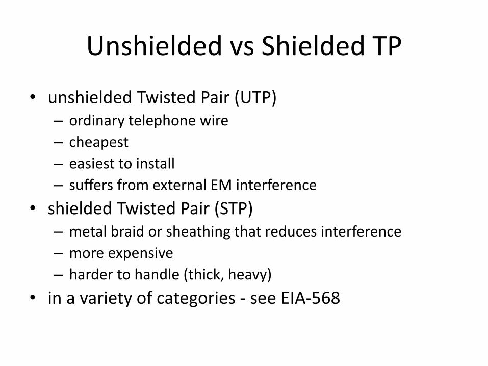
Unshielded vs Shielded TP
• unshielded Twisted Pair (UTP)– ordinary telephone wire
– cheapest
– easiest to install
– suffers from external EM interference
• shielded Twisted Pair (STP)– metal braid or sheathing that reduces interference
– more expensive
– harder to handle (thick, heavy)
• in a variety of categories - see EIA-568
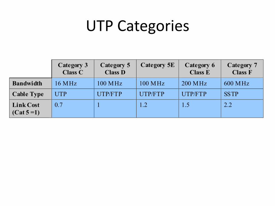
UTP Categories
Category 3
Class C
Category 5
Class D
Category 5E Category 6
Class E
Category 7
Class F
Bandwidth 16 MHz 100 MHz 100 MHz 200 MHz 600 MHz
Cable Type UTP UTP/FTP UTP/FTP UTP/FTP SSTP
Link Cost
(Cat 5 =1)
0.7 1 1.2 1.5 2.2
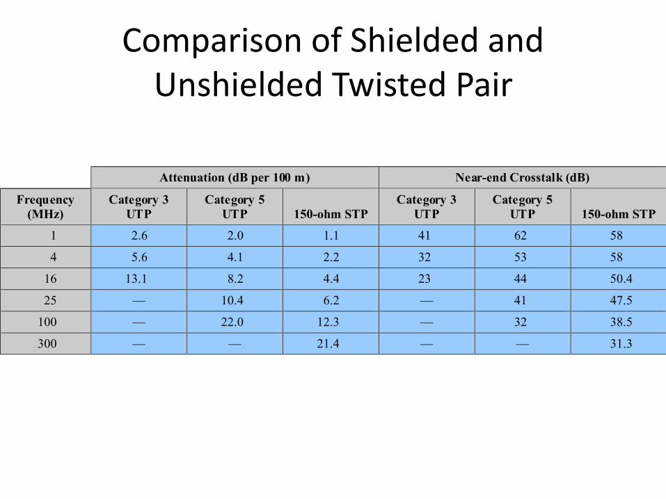
Comparison of Shielded and Unshielded Twisted Pair
Attenuation (dB per 100 m) Near-end Crosstalk (dB)
Frequency
(MHz)
Category 3
UTP
Category 5
UTP 150-ohm STP
Category 3
UTP
Category 5
UTP 150-ohm STP
1 2.6 2.0 1.1 41 62 58
4 5.6 4.1 2.2 32 53 58
16 13.1 8.2 4.4 23 44 50.4
25 — 10.4 6.2 — 41 47.5
100 — 22.0 12.3 — 32 38.5
300 — — 21.4 — — 31.3
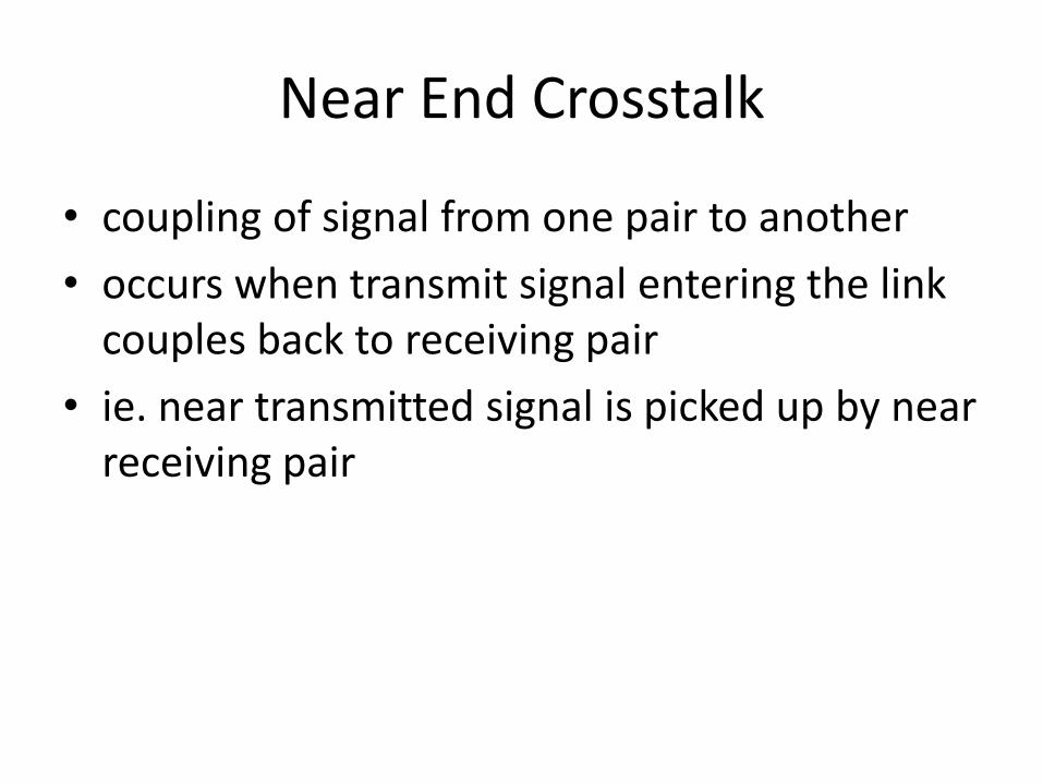
Near End Crosstalk
• coupling of signal from one pair to another
• occurs when transmit signal entering the link couples back to receiving pair
• ie. near transmitted signal is picked up by near receiving pair
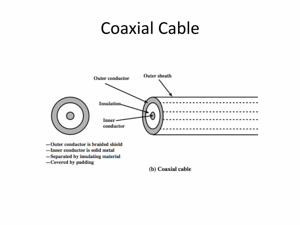
Coaxial Cable
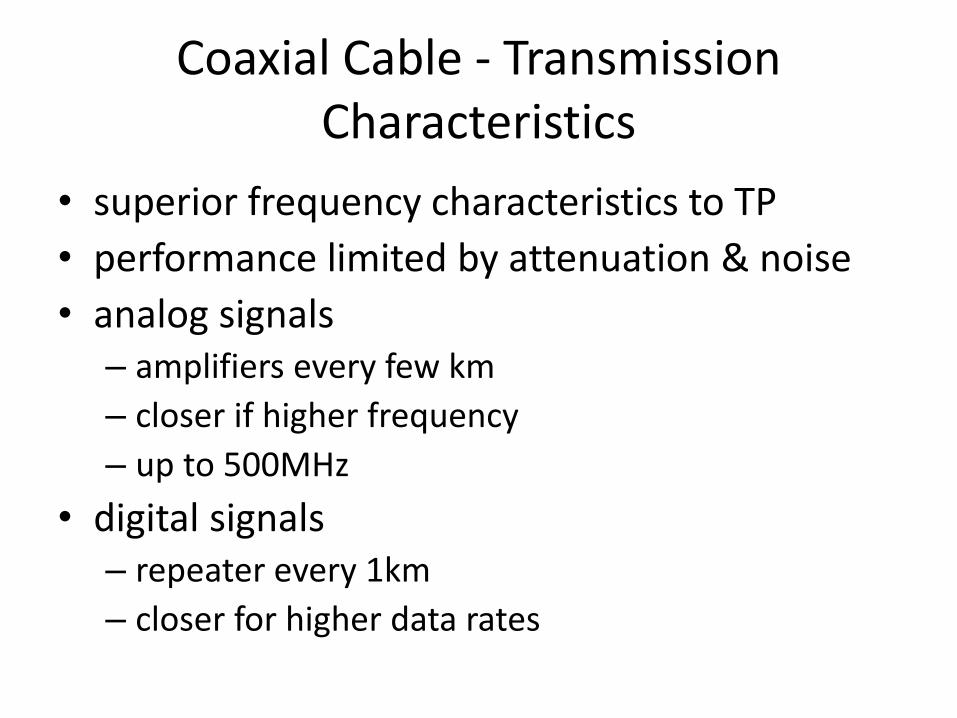
Coaxial Cable - Transmission Characteristics
• superior frequency characteristics to TP
• performance limited by attenuation & noise
• analog signals– amplifiers every few km
– closer if higher frequency
– up to 500MHz
• digital signals– repeater every 1km
– closer for higher data rates
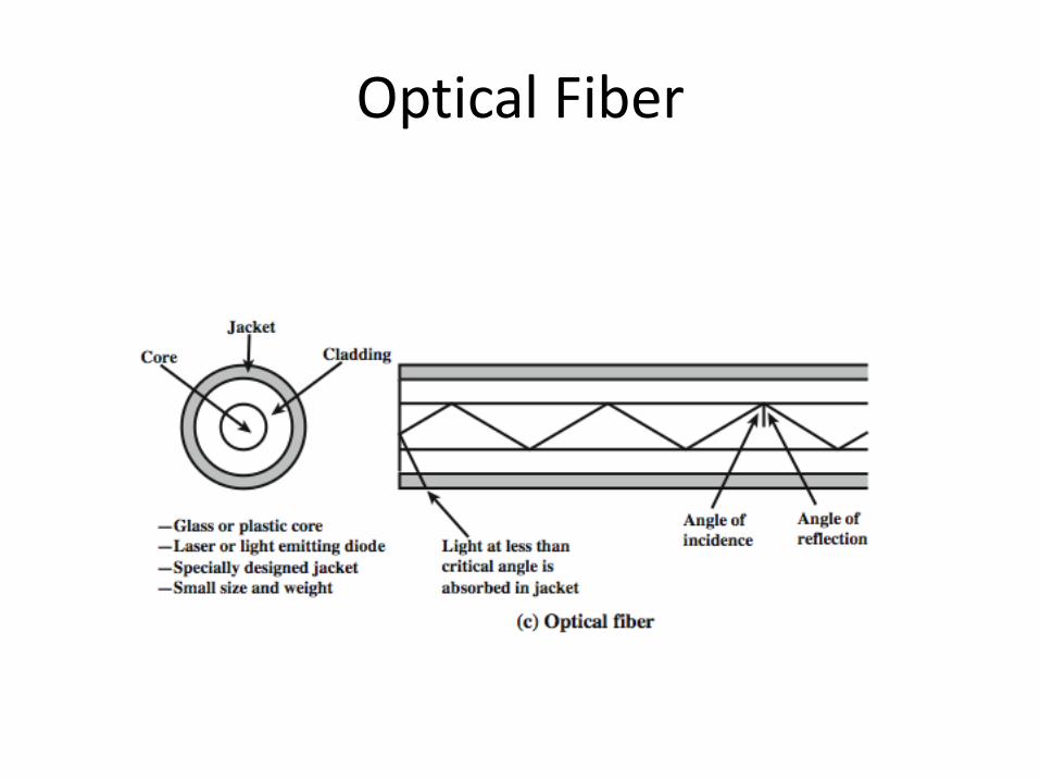
Optical Fiber
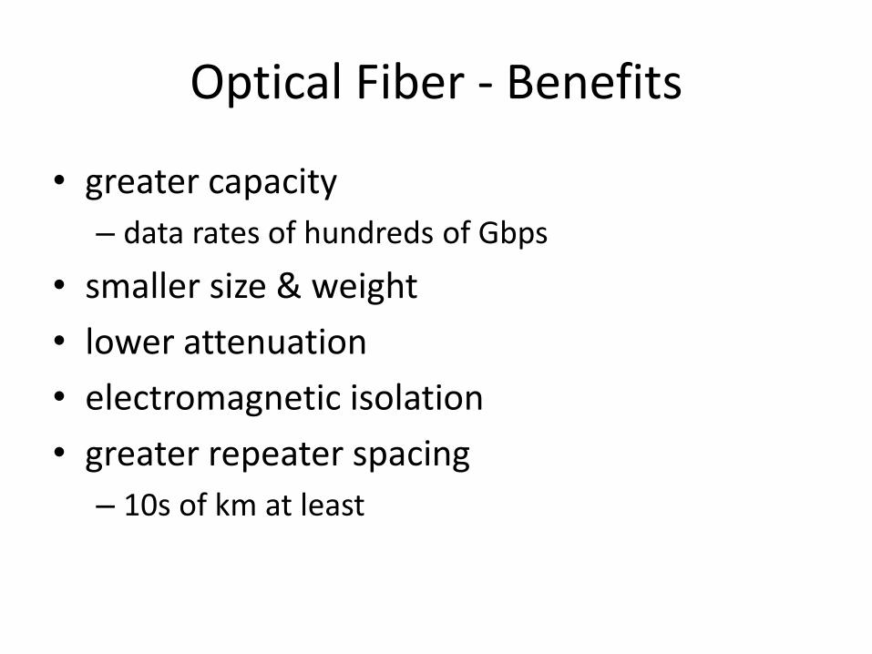
Optical Fiber - Benefits
• greater capacity
– data rates of hundreds of Gbps
• smaller size & weight
• lower attenuation
• electromagnetic isolation
• greater repeater spacing
– 10s of km at least

Optical Fiber - Transmission Characteristics
• uses total internal reflection to transmit light– effectively acts as wave guide for 1014 to 1015 Hz
• can use several different light sources– Light Emitting Diode (LED)
• cheaper, wider operating temp range, lasts longer
– Injection Laser Diode (ILD)• more efficient, has greater data rate
• relation of wavelength, type & data rate

Total Internal Reflection
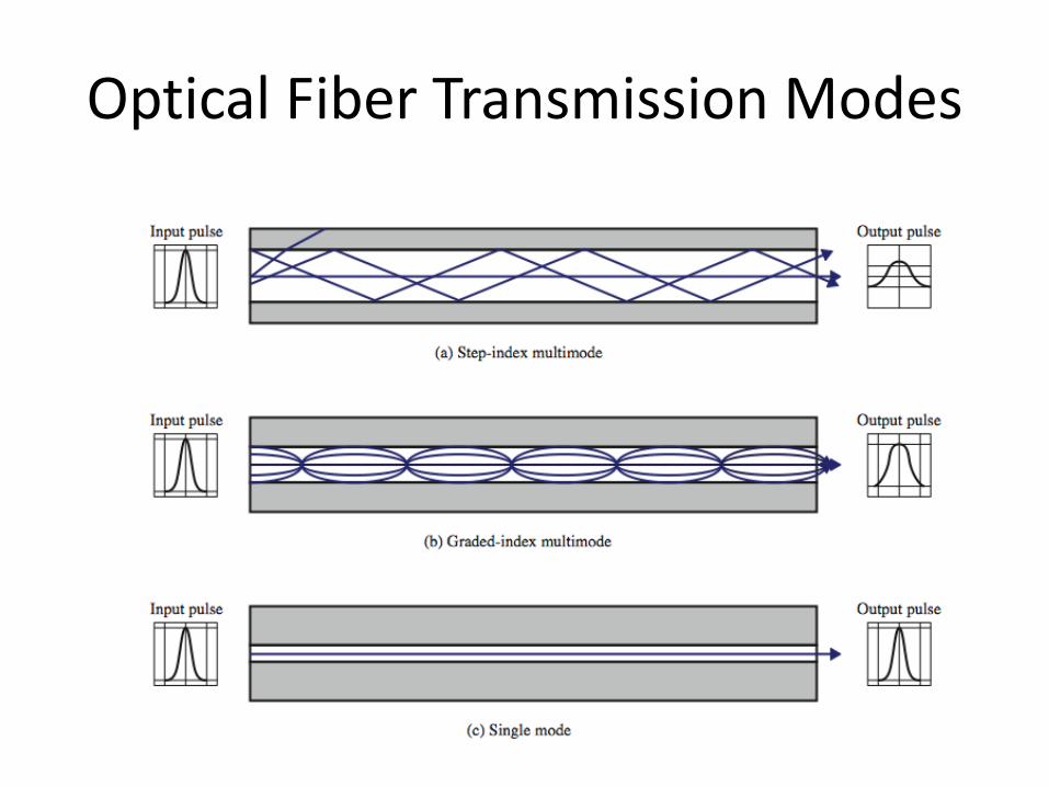
Optical Fiber Transmission Modes

Dispersion in fiber optic

Frequency Utilization for Fiber Applications
Wave length (in
vacuum) range
(nm)
Frequency
Range (THz)
Band
Label
Fiber Type Application
820 to 900 366 to 333 Multimode LAN
1280 to 1350 234 to 222 S Single mode Various
1528 to 1561 196 to 192 C Single mode WDM
1561 to 1620 192 to 185 L Single mode WDM
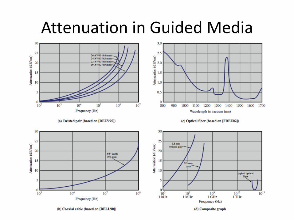
Attenuation in Guided Media
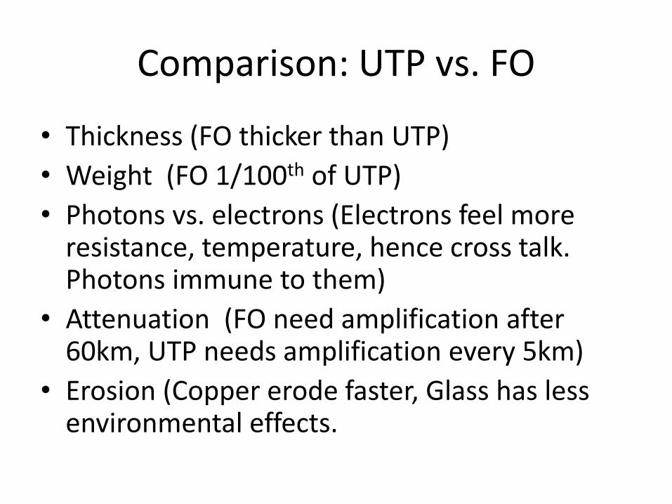
Comparison: UTP vs. FO
• Thickness (FO thicker than UTP)
• Weight (FO 1/100th of UTP)
• Photons vs. electrons (Electrons feel more resistance, temperature, hence cross talk. Photons immune to them)
• Attenuation (FO need amplification after 60km, UTP needs amplification every 5km)
• Erosion (Copper erode faster, Glass has less environmental effects.

Comparison: UTP vs. FO
• Effect of EM interference (High on UTP and less on FO)
• Leaking (High risk of eavesdropping and tapping attack in UTP then FO)
• Bandwidth (Far more in FO then UTP)• Cost (FO far more expensive than UTP)• Need for skilled engineer (in FO and not in UTP)• Technology Complexity (High in FO and easy in
UTP)• Flexibility ( High in UTP and low in FO)
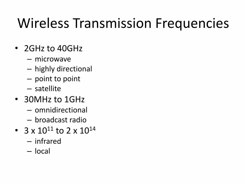
Wireless Transmission Frequencies
• 2GHz to 40GHz– microwave– highly directional– point to point– satellite
• 30MHz to 1GHz– omnidirectional– broadcast radio
• 3 x 10¹¹ to 2 x 10¹⁴
– infrared– local
Antennas
• electrical conductor used to radiate or collect electromagnetic energy
• transmission antenna
– radio frequency energy from transmitter
– converted to electromagnetic energy byy antenna
– radiated into surrounding environment
• reception antenna
– electromagnetic energy impinging on antenna
– converted to radio frequency electrical energy
– fed to receiver
• same antenna is often used for both purposes

Radiation Pattern
• power radiated in all directions
• not same performance in all directions
– as seen in a radiation pattern diagram
• an isotropic antenna is a (theoretical) point in space
– radiates in all directions equally
– with a spherical radiation pattern
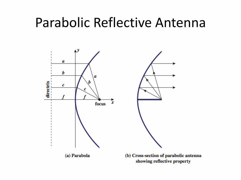
Parabolic Reflective Antenna

Antenna Gain
• measure of directionality of antenna
• power output in particular direction verses that produced by an isotropic antenna
• measured in decibels (dB)
• results in loss in power in another direction
• effective area relates to size and shape
– related to gain

Terrestrial Microwave
• used for long haul telecommunications
• and short point-to-point links
• requires fewer repeaters but line of sight
• use a parabolic dish to focus a narrow beam onto a receiver antenna
• 1-40GHz frequencies
• higher frequencies give higher data rates
• main source of loss is attenuation– distance, rainfall
• also interference
Satellite Microwave
• satellite is relay station• receives on one frequency, amplifies or repeats
signal and transmits on another frequency– eg. uplink 5.925-6.425 GHz & downlink 3.7-4.2 GHz
• typically requires geo-stationary orbit– height of 35,784km– spaced at least 3-4° apart
• typical uses– television– long distance telephone– private business networks– global positioning
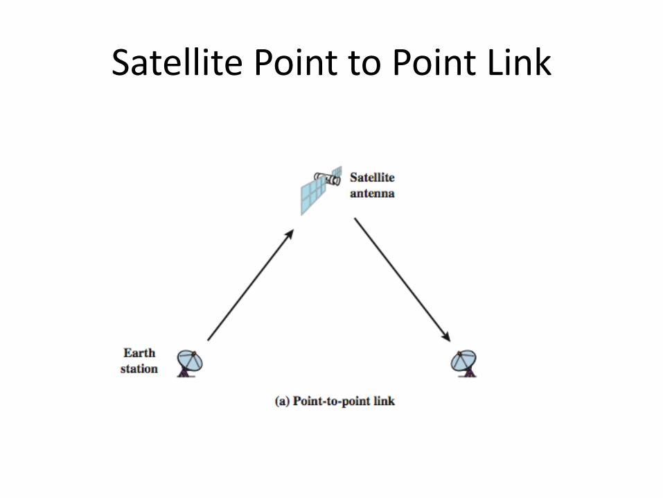
Satellite Point to Point Link
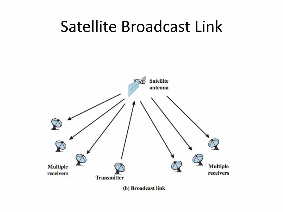
Satellite Broadcast Link
Broadcast Radio
• radio is 3kHz to 300GHz
• use broadcast radio, 30MHz - 1GHz, for:
– FM radio
– UHF and VHF television
• is omnidirectional
• still need line of sight
• suffers from multipath interference
– reflections from land, water, other objects
Infrared
• modulate noncoherent infrared light
• end line of sight (or reflection)
• are blocked by walls
• no licenses required
• typical uses– TV remote control
– IRD port
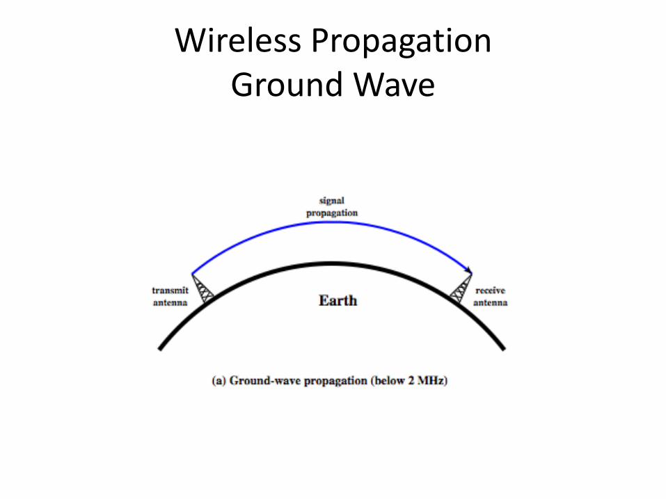
Wireless PropagationGround Wave
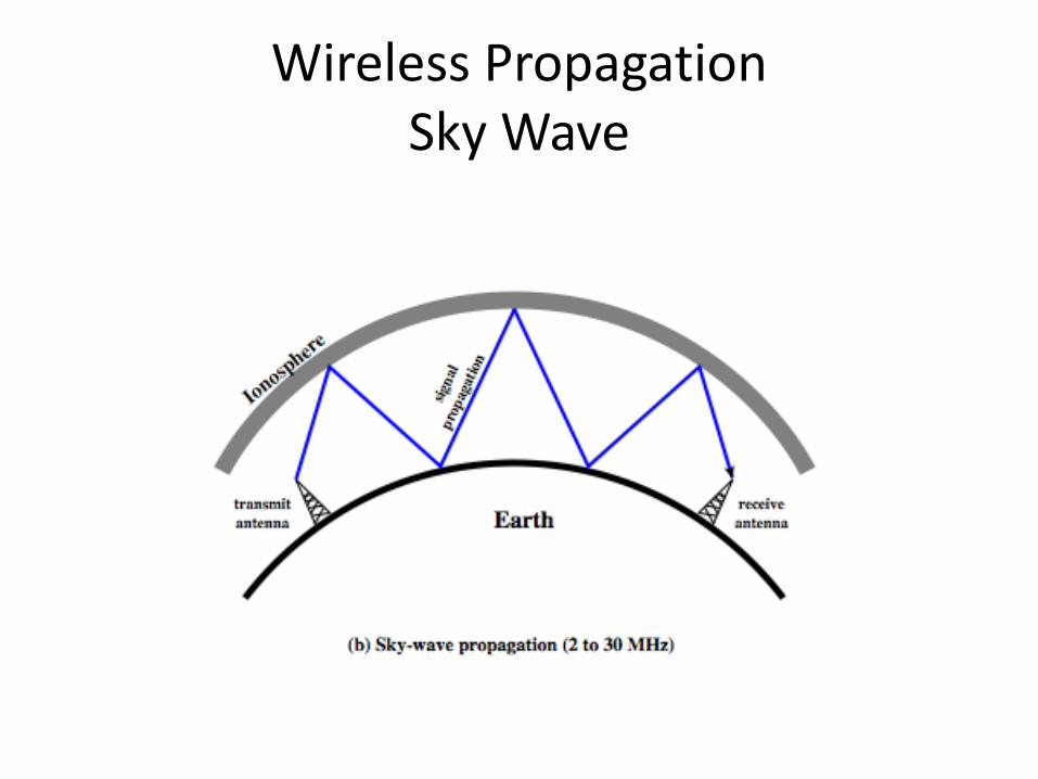
Wireless PropagationSky Wave
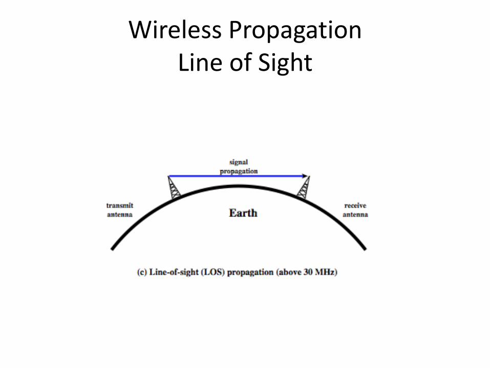
Wireless PropagationLine of Sight
Refraction
• velocity of electromagnetic wave is a function of density of material~3 x 10⁸ m/s in vacuum, less in anything else
• speed changes as move between media• Index of refraction (refractive index) is
– sin(incidence)/sin(refraction)
– varies with wavelength
• have gradual bending if medium density varies– density of atmosphere decreases with height– results in bending towards earth of radio waves– hence optical and radio horizons differ

Line of Sight Transmission
• Free space loss
– loss of signal with distance
• Atmospheric Absorption
– from water vapour and oxygen absorption
• Multipath
– multiple interfering signals from reflections
• Refraction
– bending signal away from receiver
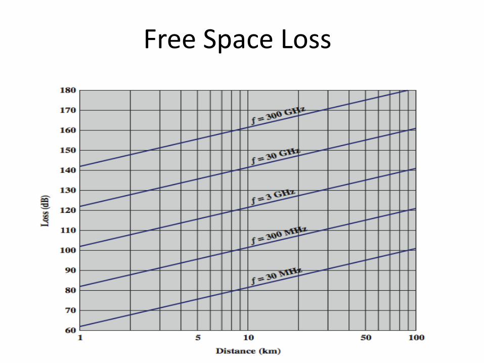
Free Space Loss
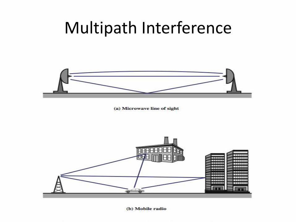
Multipath Interference
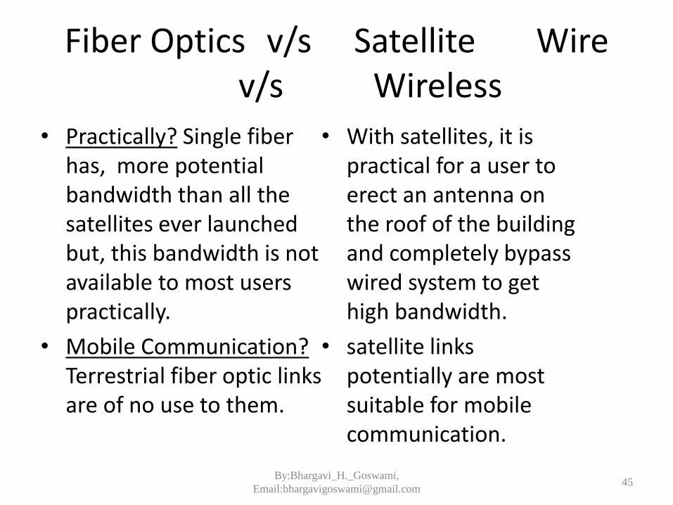
Fiber Optics v/s Satellite Wire v/s Wireless
• Practically? Single fiber has, more potential bandwidth than all the satellites ever launched but, this bandwidth is not available to most users practically.
• Mobile Communication?Terrestrial fiber optic links are of no use to them.
• With satellites, it is practical for a user to erect an antenna on the roof of the building and completely bypass wired system to get high bandwidth.
• satellite links potentially are most suitable for mobile communication.
45By:Bhargavi_H._Goswami,
Email:[email protected]
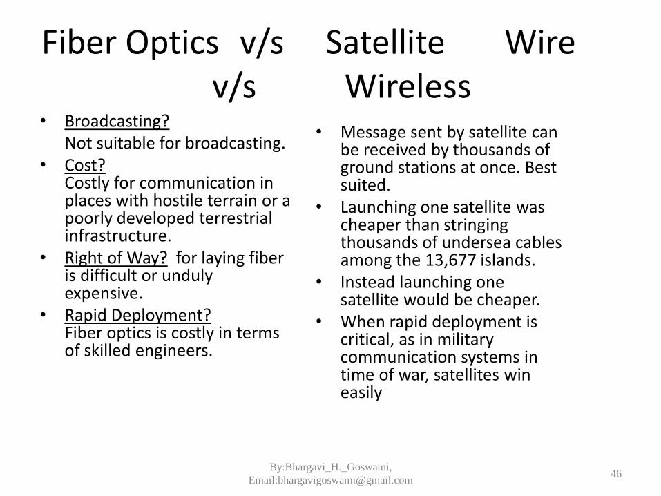
• Broadcasting?Not suitable for broadcasting.
• Cost?Costly for communication in places with hostile terrain or a poorly developed terrestrial infrastructure.
• Right of Way? for laying fiber is difficult or unduly expensive.
• Rapid Deployment?Fiber optics is costly in terms of skilled engineers.
• Message sent by satellite can be received by thousands of ground stations at once. Best suited.
• Launching one satellite was cheaper than stringing thousands of undersea cables among the 13,677 islands.
• Instead launching one satellite would be cheaper.
• When rapid deployment is critical, as in military communication systems in time of war, satellites win easily
46By:Bhargavi_H._Goswami,
Email:[email protected]
Fiber Optics v/s Satellite Wire v/s Wireless
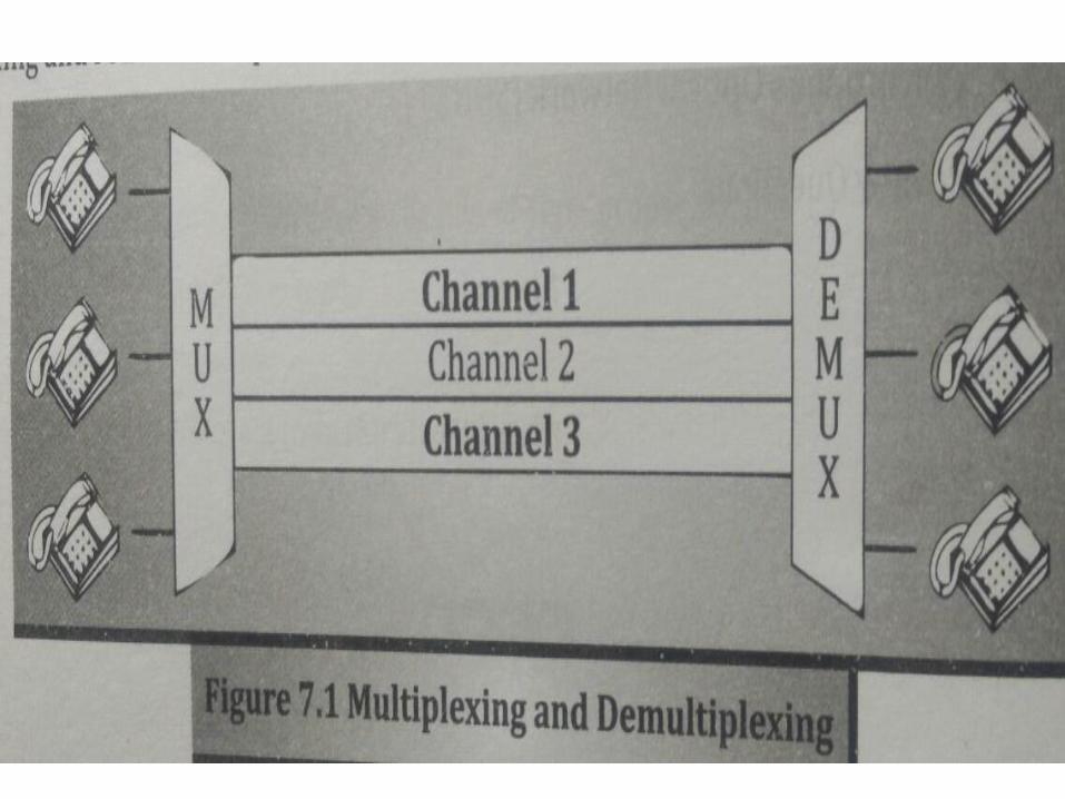
MULTIPLEXING
• MUX – DEMUX
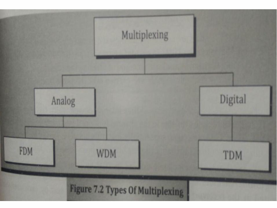
• TYPES
– FREQUENCY DIVISION MULTIPLEXING
– TIME DIVISION MULTIPLEXING
• ASYNCHRONOUS V/S SYNCHRONOUS TDM
– WAVELENGTH DIVISION MULTIPLEXING
– SONET MULTIPLEXING (SYNCHRONOUS – OPTICAL NETWORK MULTIPLEXING)
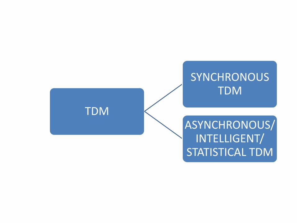
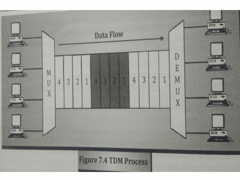
TDM
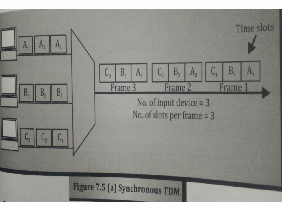
SYNCHRONOUS TDM
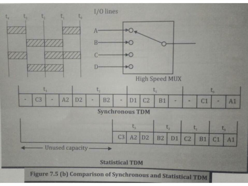
ASYNCHRONOUS/ INTELLIGENT/
STATISTICAL TDM

WDM – Wavelength Division Multiplexing
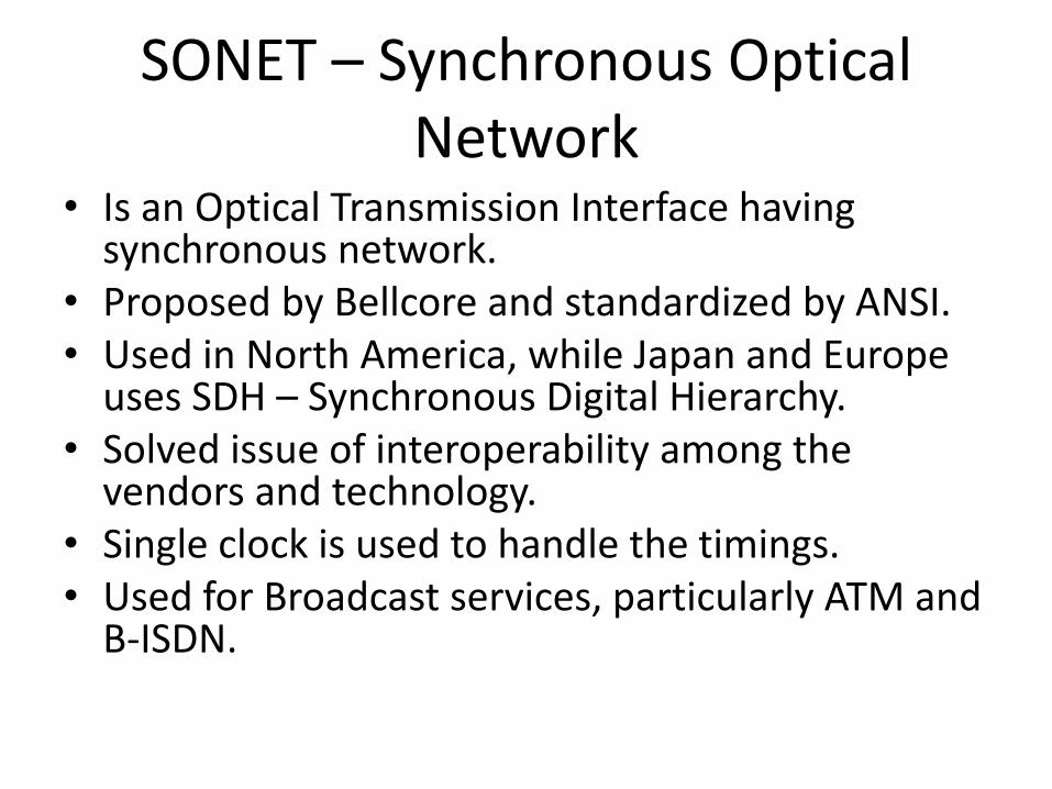
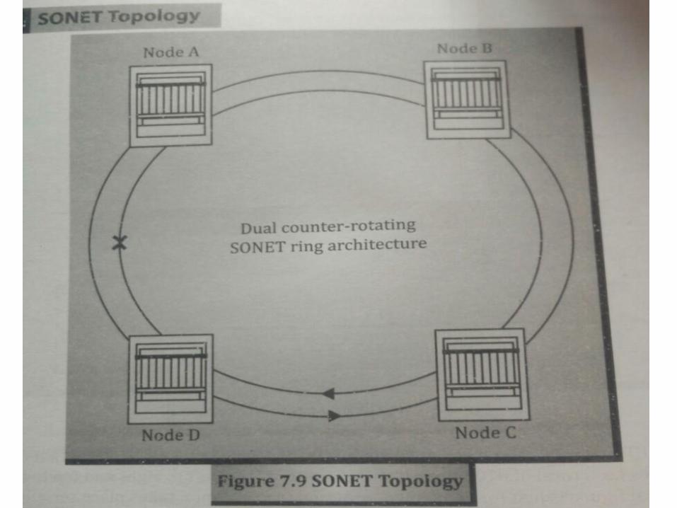
SONET – Synchronous Optical Network
• Is an Optical Transmission Interface having synchronous network.
• Proposed by Bellcore and standardized by ANSI.• Used in North America, while Japan and Europe
uses SDH – Synchronous Digital Hierarchy.• Solved issue of interoperability among the
vendors and technology.• Single clock is used to handle the timings. • Used for Broadcast services, particularly ATM and
B-ISDN.
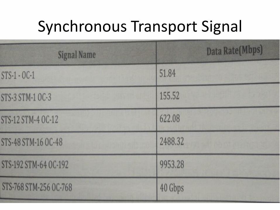
Synchronous Transport Signal

PHYSICAL CONFIGURATION
• STS Multiplexers
• Regenerators
• Add/Drop Multiplexers
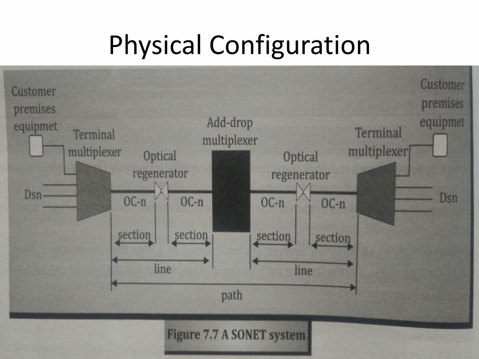
Physical Configuration
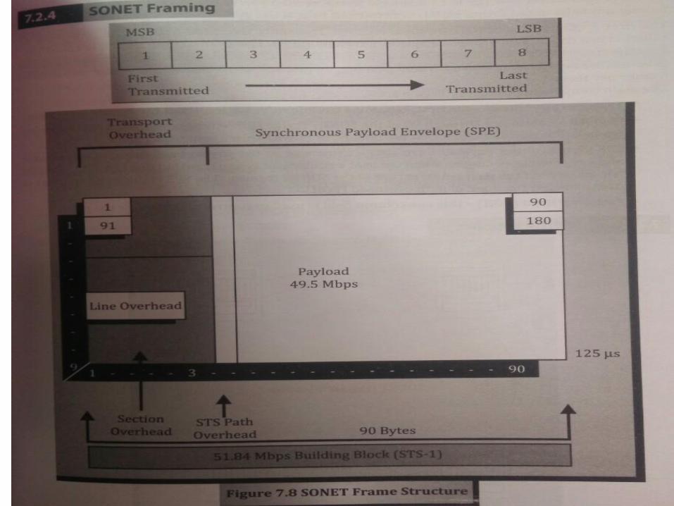
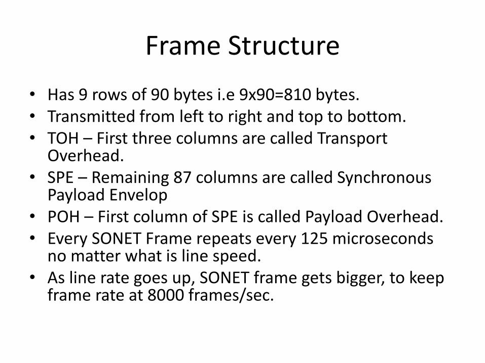
Frame Structure
• Has 9 rows of 90 bytes i.e 9x90=810 bytes.• Transmitted from left to right and top to bottom.• TOH – First three columns are called Transport
Overhead.• SPE – Remaining 87 columns are called Synchronous
Payload Envelop• POH – First column of SPE is called Payload Overhead.• Every SONET Frame repeats every 125 microseconds
no matter what is line speed.• As line rate goes up, SONET frame gets bigger, to keep
frame rate at 8000 frames/sec.

CIRCUIT SWITCHING
CROSSBARMULTISTAGE
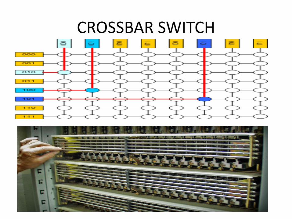
CROSSBAR SWITCH
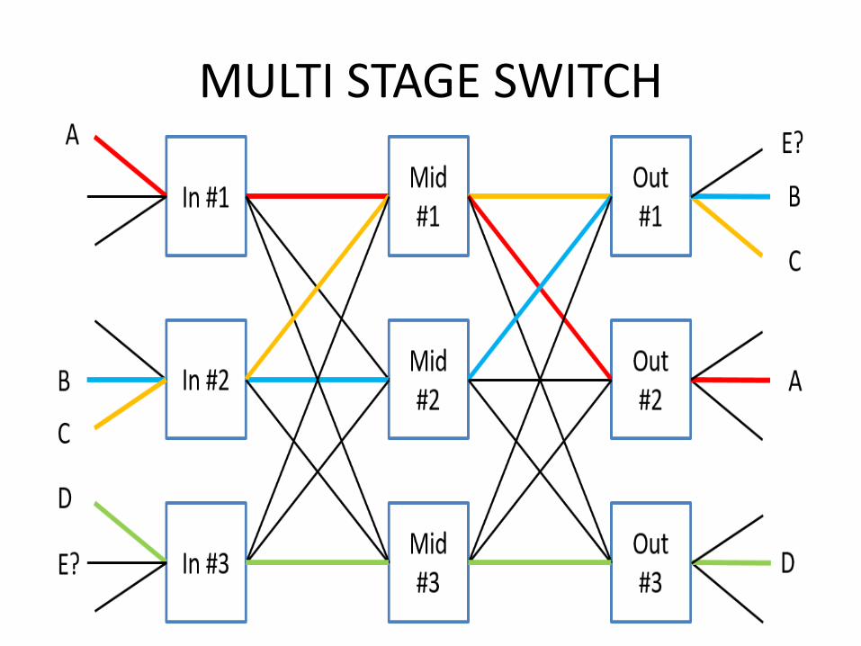
MULTI STAGE SWITCH
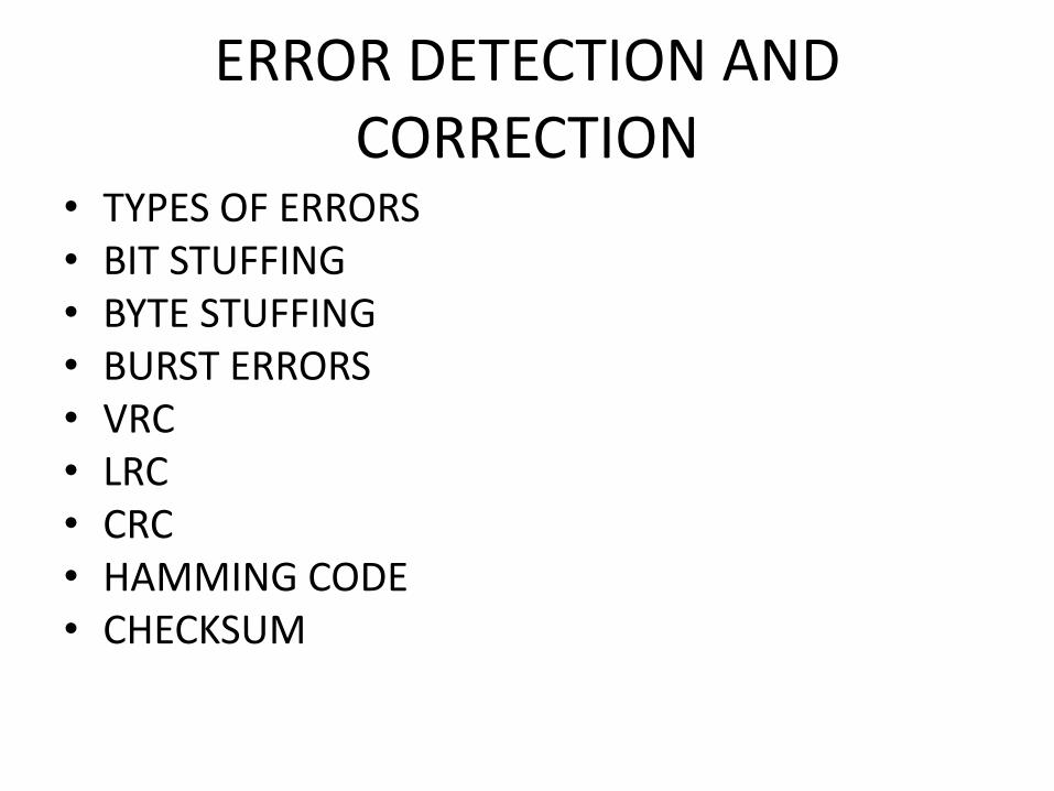
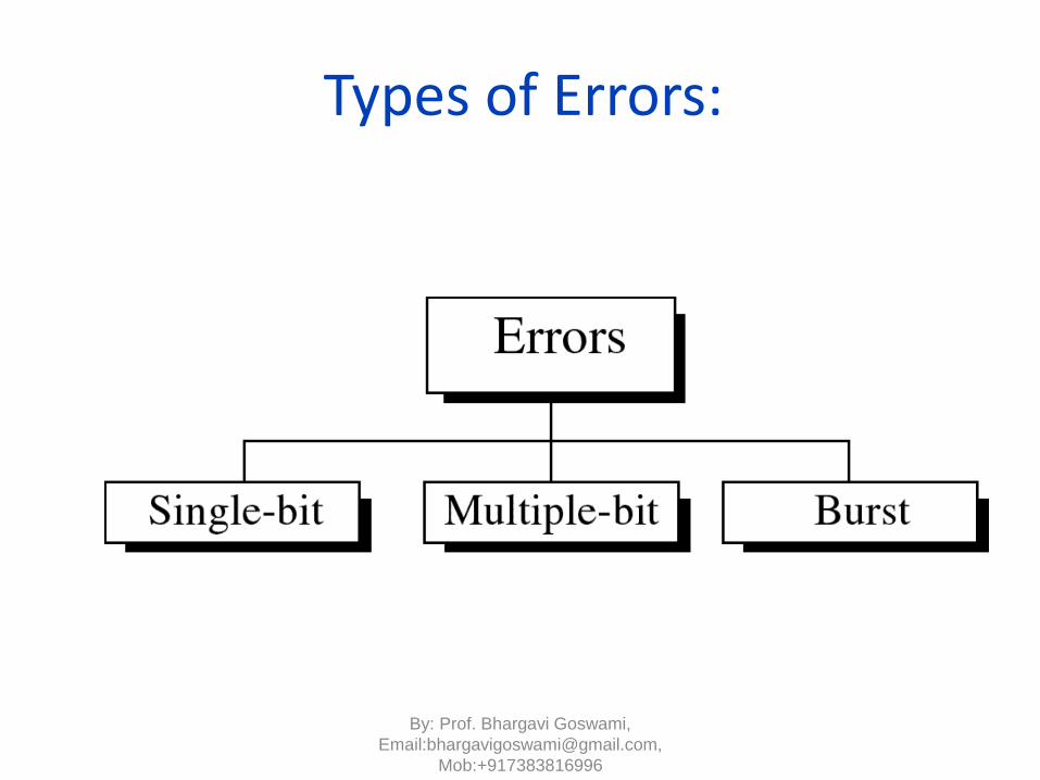
ERROR DETECTION AND CORRECTION
• TYPES OF ERRORS• BIT STUFFING• BYTE STUFFING• BURST ERRORS• VRC• LRC• CRC• HAMMING CODE• CHECKSUM
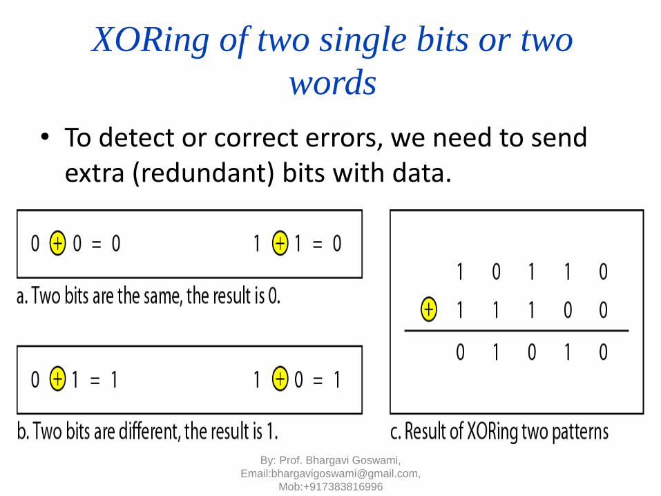
XORing of two single bits or two
words
• To detect or correct errors, we need to send extra (redundant) bits with data.
By: Prof. Bhargavi Goswami,
Email:[email protected],
Mob:+917383816996

Detection Methods:
• Detection methods
– VRC(Vertical Redundancy Check)
– LRC(Longitudinal Redundancy)
– CRC(Cyclical redundancy Check)
– Checksum
By: Prof. Bhargavi Goswami,
Email:[email protected],
Mob:+917383816996
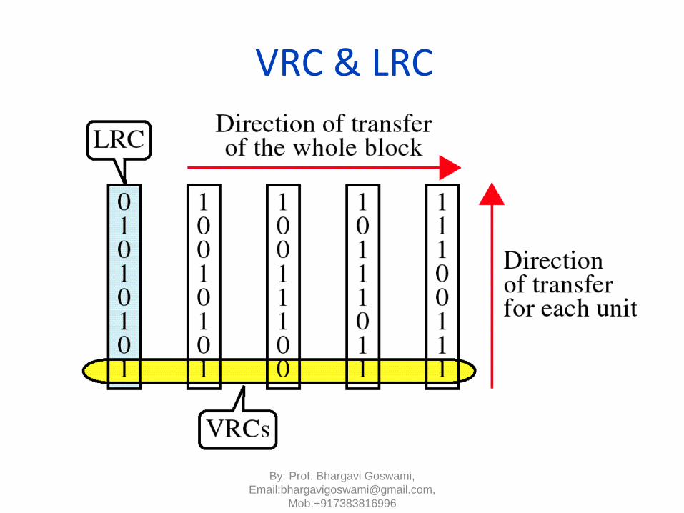
VRC
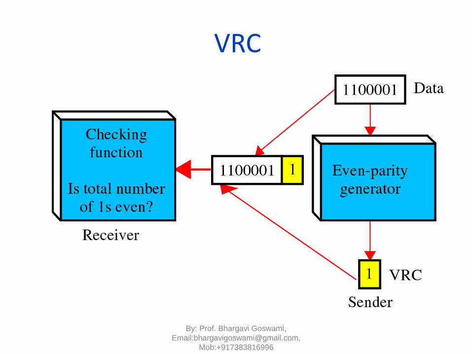
• VRC(Vertical Redundancy Check)
– A parity bit is added to every data unit so that the total number of 1s(including the parity bit) becomes even for even-parity check or odd for odd-parity check
– VRC can detect all single-bit errors.
– It can detect multiple-bit or burst errors only the total number of errors is odd.
• Even parity VRC concept is given in next fig
By: Prof. Bhargavi Goswami,
Email:[email protected],
Mob:+917383816996
LRC
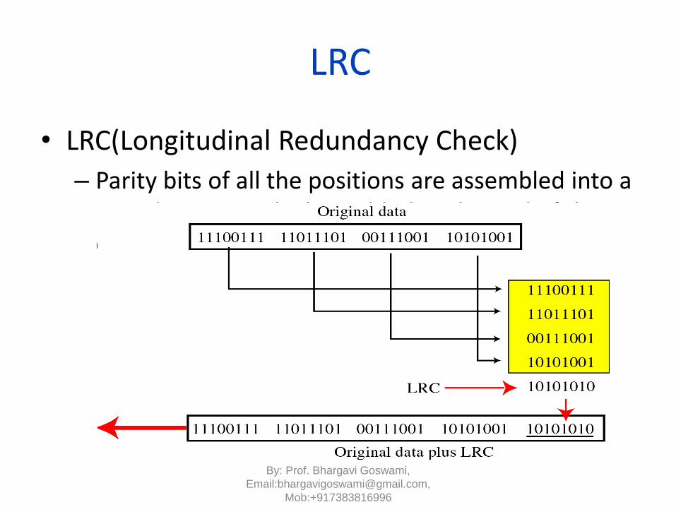
• LRC(Longitudinal Redundancy Check)
– Parity bits of all the positions are assembled into a new data unit, which is added to the end of the data block
By: Prof. Bhargavi Goswami,
Email:[email protected],
Mob:+917383816996
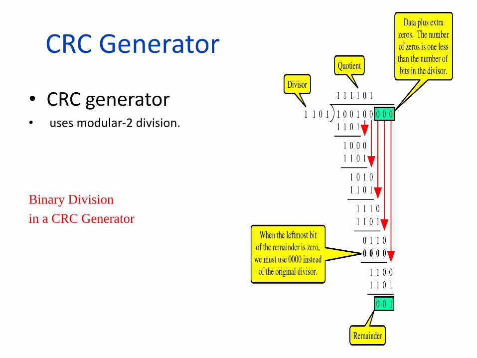
CRC Generator
• CRC generator• uses modular-2 division.
Binary Division
in a CRC Generator
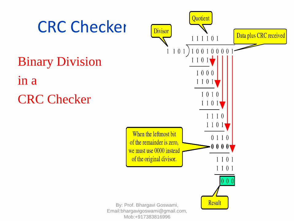
CRC Checker
Binary Division
in a
CRC Checker
By: Prof. Bhargavi Goswami,
Email:[email protected],
Mob:+917383816996

As per text book:
Calculation of the polynomial code checksum.
By: Prof. Bhargavi Goswami,
Email:[email protected],
Mob:+917383816996
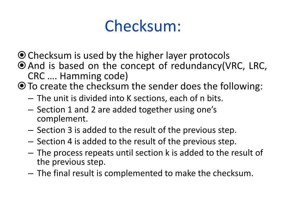
Checksum:
Checksum is used by the higher layer protocolsAnd is based on the concept of redundancy(VRC, LRC,
CRC …. Hamming code)To create the checksum the sender does the following:
– The unit is divided into K sections, each of n bits.– Section 1 and 2 are added together using one’s
complement.– Section 3 is added to the result of the previous step.– Section 4 is added to the result of the previous step.– The process repeats until section k is added to the result of
the previous step.– The final result is complemented to make the checksum.
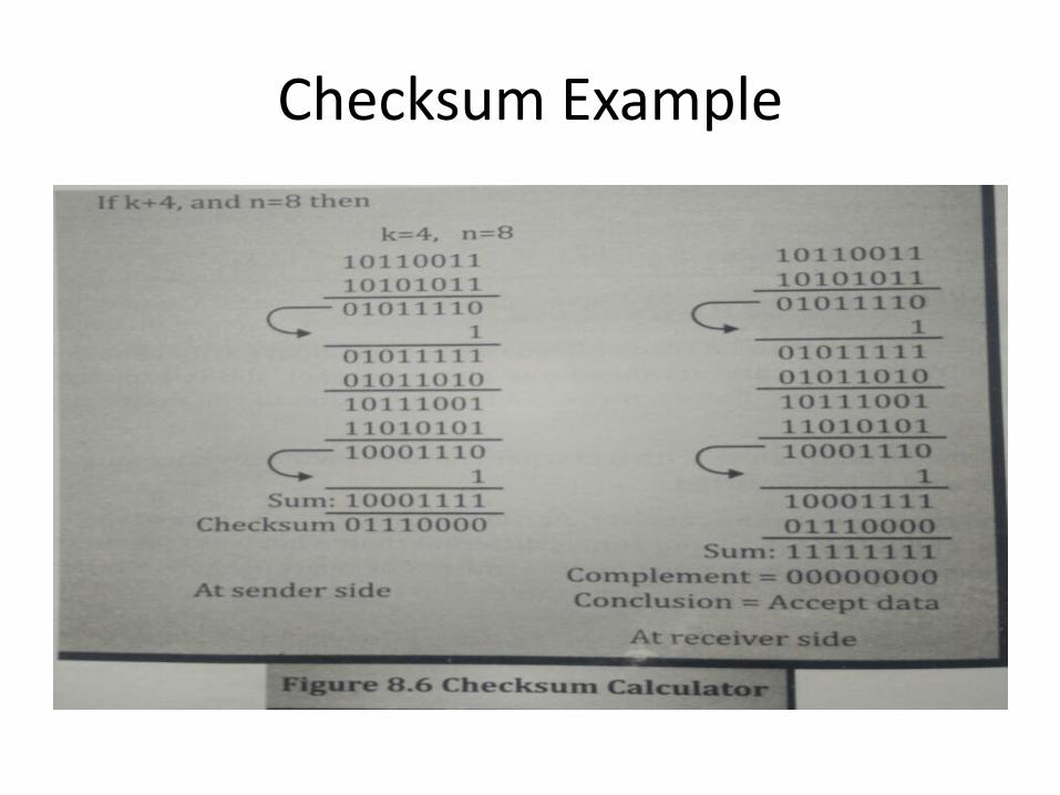
Checksum Example

Hamming code and Error
7 bit data 4 bit redundant bits makes it 11
• Redundancy for error handling• m data bits and r redundant bits• for m + r bits only one correct value of r for a
given m• one correct bit pattern requires m + r incorrect
patterns• m + r + 1 < 2 r
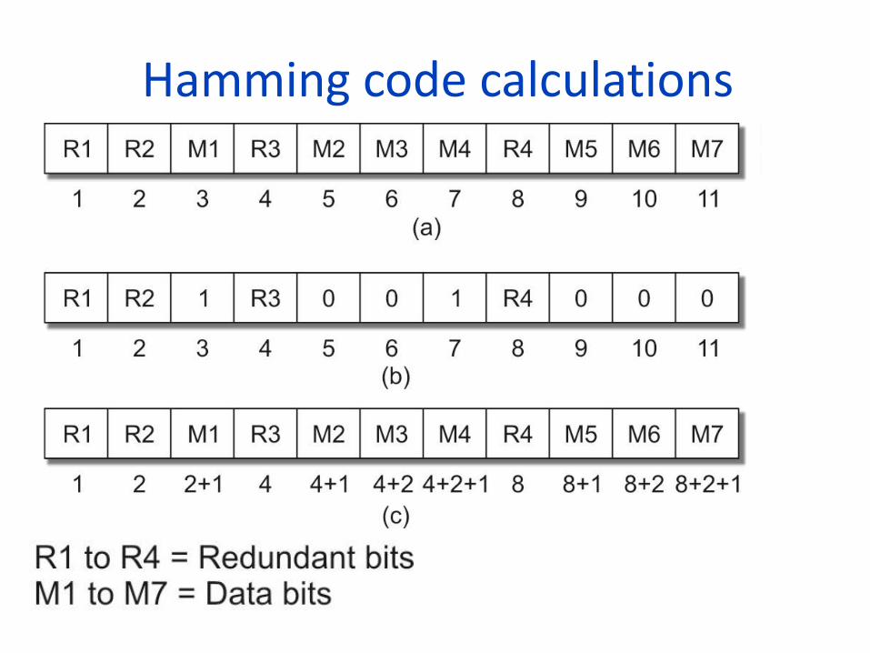
Hamming code calculations
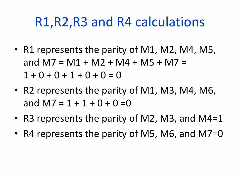
R1,R2,R3 and R4 calculations
• R1 represents the parity of M1, M2, M4, M5, and M7 = M1 + M2 + M4 + M5 + M7 = 1 + 0 + 0 + 1 + 0 + 0 = 0
• R2 represents the parity of M1, M3, M4, M6, and M7 = 1 + 1 + 0 + 0 =0
• R3 represents the parity of M2, M3, and M4=1
• R4 represents the parity of M5, M6, and M7=0
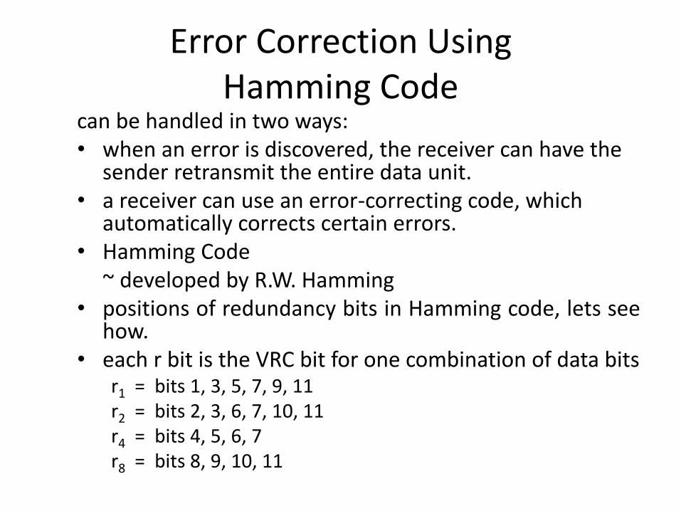
Error Correction Using Hamming Code
can be handled in two ways:• when an error is discovered, the receiver can have the
sender retransmit the entire data unit.• a receiver can use an error-correcting code, which
automatically corrects certain errors.• Hamming Code
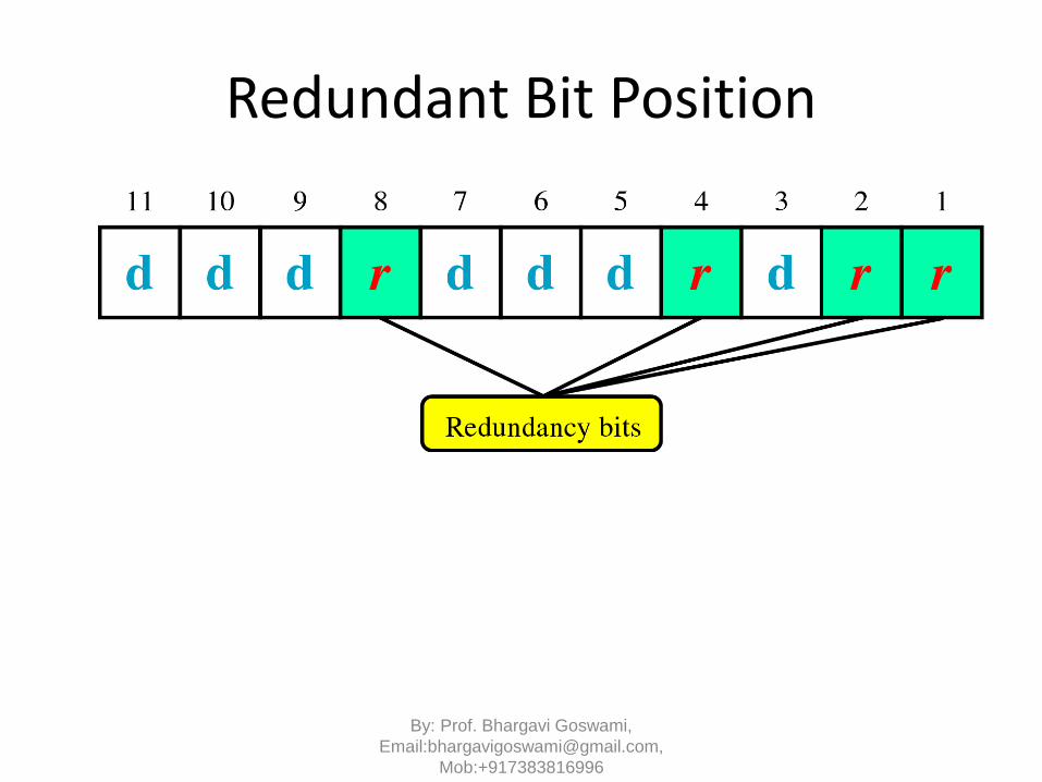
~ developed by R.W. Hamming• positions of redundancy bits in Hamming code, lets see
how.• each r bit is the VRC bit for one combination of data bits
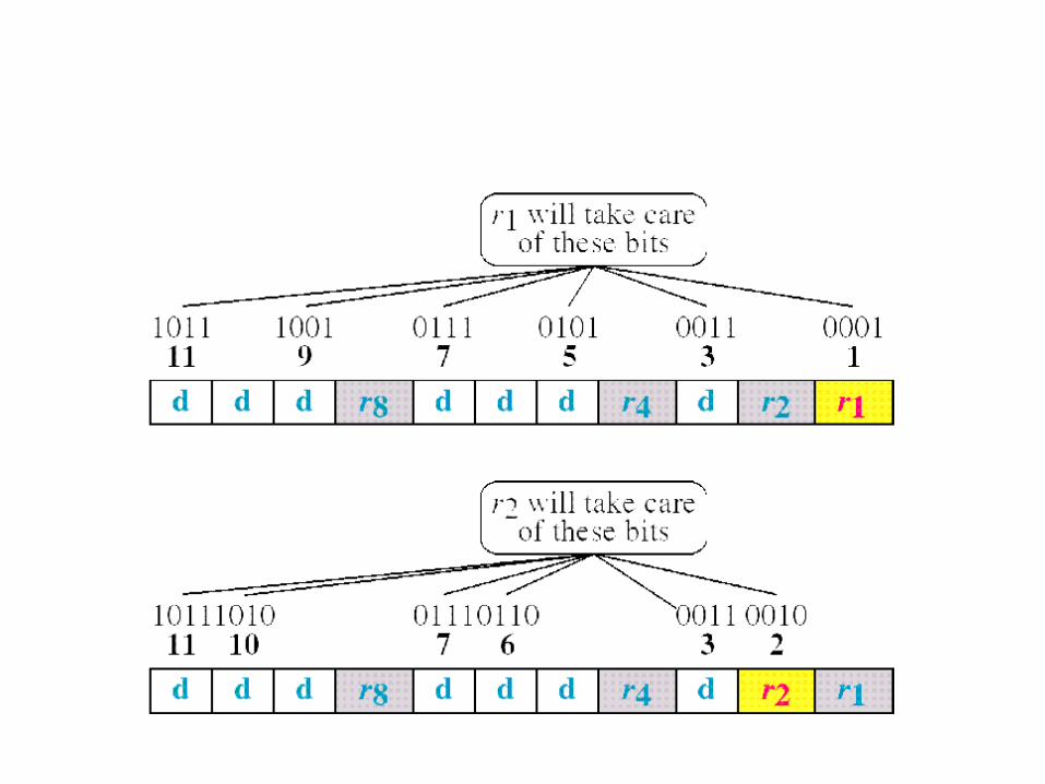
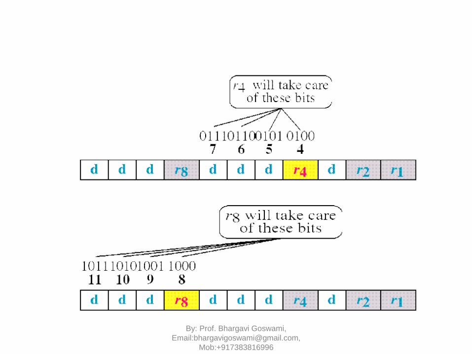
r1 = bits 1, 3, 5, 7, 9, 11r2 = bits 2, 3, 6, 7, 10, 11r4 = bits 4, 5, 6, 7r8 = bits 8, 9, 10, 11
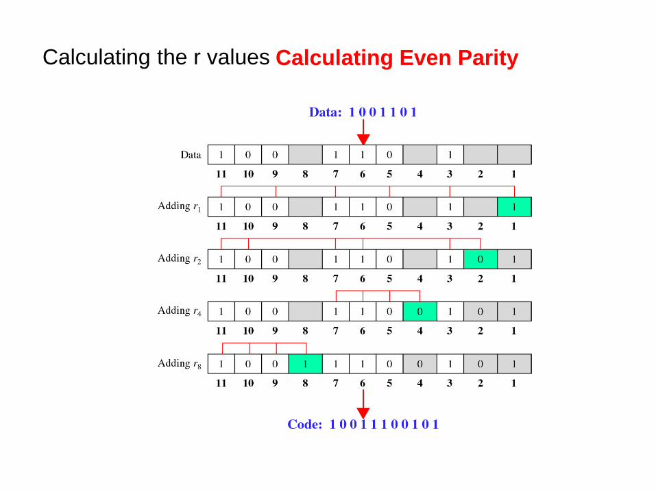
Calculating the r values Calculating Even Parity
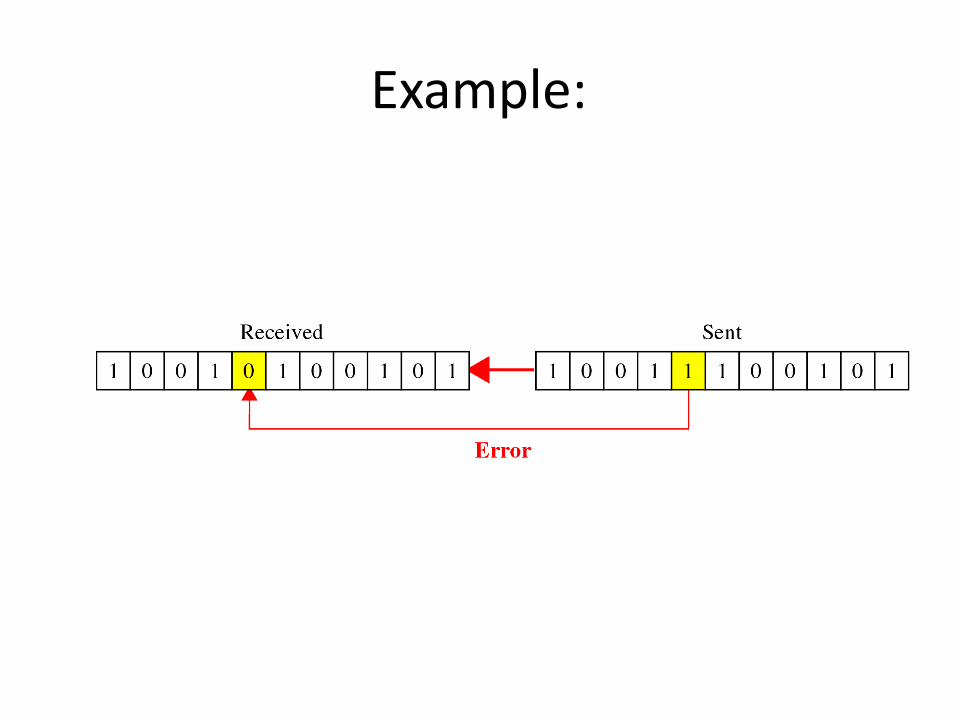
Example:

Error Detection Using Hamming Code:

THANK YOU
Start preparation for final exam….