data and computer communications chapter 5 – signal...
TRANSCRIPT

Data and Computer Communications
Chapter 5 – Signal Encoding Techniques

Computer EngineeringKyungpook National University
Terminology Encoding
Data → Signal Decoding
Signal →Data Data rate (R)
Rate, in bits per second (bps) that data are transmitted Duration or length of a bit
Time taken for transmitter to emit the bit Tb = 1/R (R = Transmission rate or data rate)
Modulation rate (signaling rate) Rate at which the signal level is changed; the rate is
expressed in baud, which means signal elements per second

Computer EngineeringKyungpook National University
Signal Encoding Techniques Digital data =>
Digital signal Analog data =>
Digital signal
Digital data => Analog signal
Analog data => Analog signal
sender receiver
link

Computer EngineeringKyungpook National University
Digital Data, Digital Signal
Digital signalDiscrete, discontinuous voltage pulsesEach pulse is a signal elementBinary data encoded into signal elements

Computer EngineeringKyungpook National University
Interpreting Digital Signals
Tasks involved in interpreting digital
signal at the receiver:
Timing of bits - when they start and end
(synchronization)
Signal levels or transitions
Factors affecting signal interpretation:
Signal to noise ratio
Data rate
Bandwidth

Computer EngineeringKyungpook National University
Synchronization The receiver must find beginning/end of each
signal To prevent timing drift between transmitter and
receiver, their clocks must somehow be synchronized
Out of sync
In sync
Sending time of each signal at sender
Picking-up time of each signal at receiver

Computer EngineeringKyungpook National University
Encoding Schemes

Computer EngineeringKyungpook National University
Biphase Encoding Manchester
Has transition in middle of each bit period Low to high represents “1” High to low represents “0” Transition serves as clock and data Used by IEEE 802 LAN standard
Differential Manchester Transition at start of bit period representing “0” No transition at start of bit period representing “1” Mid-bit transition is clocking only

Computer EngineeringKyungpook National University
Synchronization vs Transition Embed the clocking information in the data signal
So, transition provides clocking (timing) information Receiver adjusts its picking-up time by referring to transition
times More transitions facilitates synchronization
Actual transition
Receiver expects transitions here using its own clockTime drift
1st bit 2nd bit 3rd bit
DataPreamble Headersync Frame = Data plus header (control
information)
Computer EngineeringKyungpook National University
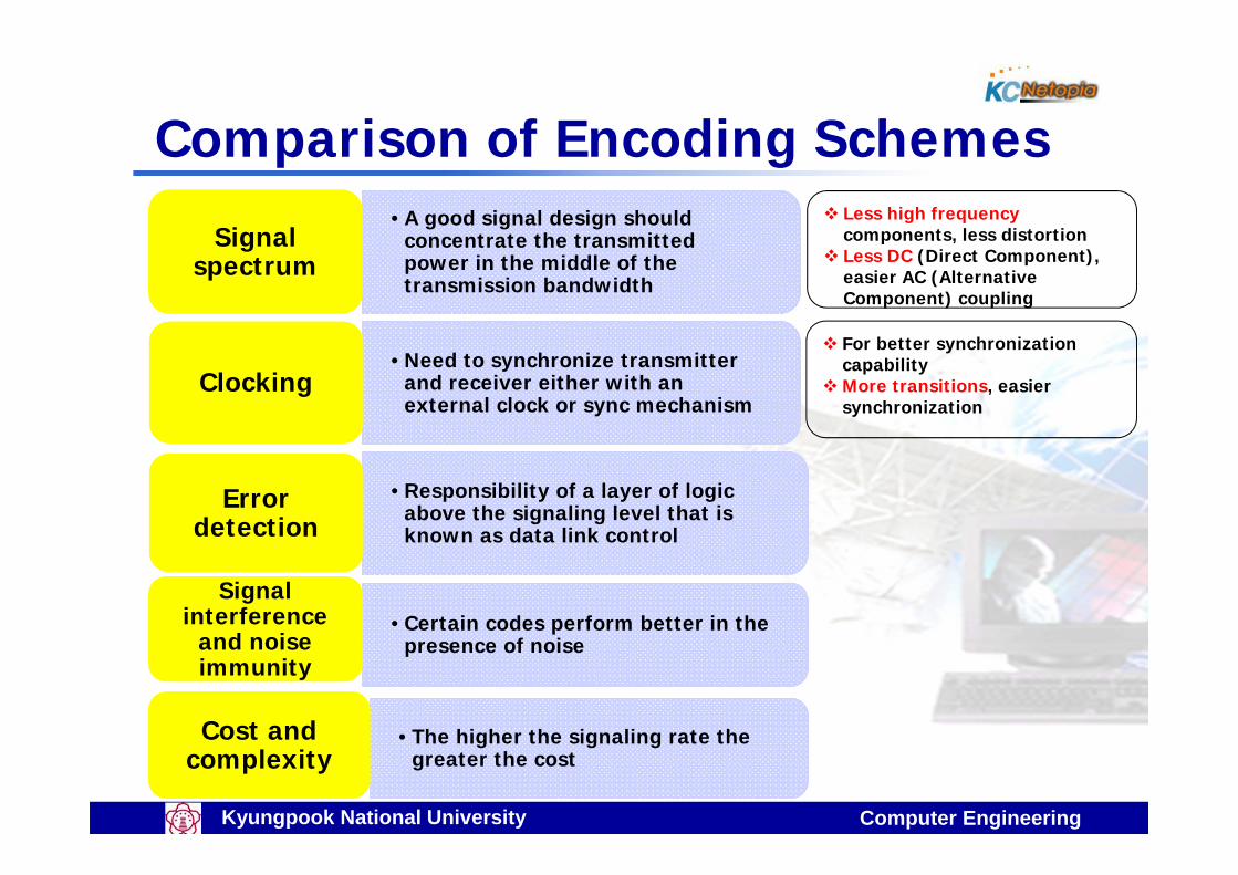
Comparison of Encoding Schemes• A good signal design should
concentrate the transmitted power in the middle of the transmission bandwidth
Signal spectrum
Signal spectrum
• Need to synchronize transmitter and receiver either with an external clock or sync mechanism
ClockingClocking
• Responsibility of a layer of logic above the signaling level that is known as data link control
Error detection
Error detection
• Certain codes perform better in the presence of noise
Signal interference
and noise immunity
Signal interference
and noise immunity
• The higher the signaling rate the greater the cost
Cost and complexityCost and
complexity
Less high frequency components, less distortion
Less DC (Direct Component), easier AC (Alternative Component) coupling
For better synchronization capability
More transitions, easier synchronization

Computer EngineeringKyungpook National University
Signal SpectrumNRZ = Nonreturn to zero levelNRZI = Nonreturn to zero invertedAMI = Alternate mark inversionB8ZS = Bipolar with 8 zeros substitutionHDB3 = High density bipolar - 3 zeros
f = frequency (Hz)R = data rate (bps)
Mea
n sq
uare
vol
tage
per
uni
t ba
ndw
idth
Normalized frequency ( f / R )
NRZ-L,NRZI
B8ZS, HDB3
AMI, Pseudoternary
Manchester,Differential Manchester

Computer EngineeringKyungpook National University
NRZ vs ManchesterNRZ Manchester
Spectrum
HighFrequency
Less (Make good use of givenbandwidth)
More (Requires more bandwidth)
DC Yes No
SynchronizationCapability No Yes (self clocking)
Pros Easy to engineer More reliable (easy error detection)
Cons Not often used for signal transmission
Maximum modulation rate is twice NRZ

Computer EngineeringKyungpook National University
Digital Data, Analog Signal
Main use is public telephone systemHas freq range of 300Hz to 3400HzUse modem (modulator-demodulator)
Encoding techniquesChange shape of carrier depending on data (cf) carrier = signal carrying dataAmplitude shift keying (ASK) Frequency shift keying (FSK)Phase shift keying (PSK)

Computer EngineeringKyungpook National University
ASK: Encode 0/1 by different amplitudes of carrier “0” = zero amplitude “1” = high amplitude
FSK: Two binary values represented by two different frequencies “0” = low frequency “1” = high frequency Less susceptible to error than
ASK
PSK: Phase of carrier signal is shifted to represent data “0” = No change of phase “1” = 180o change of phase
ASK, FSK, PSK

Computer EngineeringKyungpook National University
Quadrature PSK Each signal element represents two bits
00 - Shifts of 0o
01 - Shifts of 90o
10 - Shifts of 180o
11 - Shifts of 270o
Split input data stream in two & modulate onto carrier

Computer EngineeringKyungpook National University
Quadrature Amplitude Modulation Combination of ASK and PSK
Each carrier is ASK and PSK modulated simultaneously Receiver extracts two original bits from one signal by
demodulation
QAM used on asymmetric digital subscriber line (ADSL) and some wireless
Phase shift
0o 90o 180o 270o
Amplitude Low 000 010 100 110
High 001 011 101 111

Computer EngineeringKyungpook National University
Example : QAM Signal Elements
45°
0°
90°
135°
180°
225°
270°
315°
1010
10000010
0111
0011
1111
1011
1100
01001110
0110
0001 1001
0101
0000
1101
Total 16 states Phase shift - 8 states
(0o,45o,90o,135o,180o,225o,270o,
315o) Amplitude - 2 states (high, low)
Sender modulates 4 bits into one signal
Receiver extracts four original bits from one signal by demodulation
QAM used on asymmetric digital subscriber line (ADSL) and some wireless

Computer EngineeringKyungpook National University
Analog Data, Digital Signal
Digitization is conversion of analog data into digital data Sampling
How often the analog signal should be sampled?? (Sampling frequency)
QuantizationHow many bits are used to express each sample??
Samples3.0
1.4
6.2
1.32.8
5.94.1
31
6
13
64 Quantized samples
0 1 1 0 0 1 1 1 0 0 0 1 0 1 1 1 1 0 1 0 0 Digitized output
Analog data
Sampling times

Computer EngineeringKyungpook National University
Sampling Theorem Sampling frequency > 2* (the highest frequency
contained in the signal) “If a signal is sampled at a rate higher than twice the
highest signal frequency, the samples contain all information in original signal”

Computer EngineeringKyungpook National University
Example
For 4Khz voice data, how many samples per sec? Sampling frequency = 2*4000 = 8000 samples per sec A sample per 125us
Quantization 1 sample is expressed by 1 byte Values : 0 ~ 255
So, digital output = 8000*8bits/s = 64Kbps Digital recording for 1 hour
64K * 3600sec = 230.4Mbits = 28.8Mbytes

Computer EngineeringKyungpook National University
ExampleDigitizer
1010111…111
Manchester codeAnalog data Sampled data Digitized data

Computer EngineeringKyungpook National University
Analog Data, Analog Signals Modulate carrier with analog data
Carrier
Data
Amplitude Modulation
Frequency Modulation
Phase Modulation

Computer EngineeringKyungpook National University
Summary
Digital data, digital signalsBiphase (Manchester, Differential Manchester)Comparison
Analog data, digital signalsSamplingQuantization
Digital data, analog signalsASK, FSK, PSKQuadrature amplitude modulation