data acquisition software user’s manual version 2€¦ · · 2015-10-19data acquisition...
TRANSCRIPT
Data Acquisition Software User’s Manual
Version 2.1
Triangle BioSystems International 2224 Page Rd. Suite 108 Durham, NC 27703
Phone: (919) 361‐2663 • Fax: (919) 544‐3061 www.trianglebiosystems.com

NeuroWare© User’s Manual
Version1.2 ‐1‐ 1/2014
ContentsDocument Overview ....................................................................................................................... ‐ 3 ‐
System Overview ............................................................................................................................ ‐ 3 ‐
Standard Shipped items list ............................................................................................................. ‐ 4 ‐
System Requirements ..................................................................................................................... ‐ 4 ‐
System I/O ..................................................................................................................................... ‐ 4 ‐
POWER INPUT ................................................................................................................. ‐ 5 ‐
Analog Input .................................................................................................................... ‐ 5 ‐
DATA A............................................................................................................................ ‐ 5 ‐
DATA B ............................................................................................................................ ‐ 5 ‐
USB A .............................................................................................................................. ‐ 5 ‐
USB B .............................................................................................................................. ‐ 5 ‐
GND ................................................................................................................................ ‐ 5 ‐
DATA I/O ......................................................................................................................... ‐ 5 ‐
Headstage input pinout .................................................................................................... ‐ 5 ‐
NeuroWare© Installation................................................................................................................. ‐ 6 ‐
Loading and Configuration .............................................................................................................. ‐ 8 ‐
Start NeuroWare ................................................................................................................. ‐ 8 ‐
Load a Configuration File...................................................................................................... ‐ 8 ‐
Configure NeuroWare© ........................................................................................................ ‐ 9 ‐
Load New Config.................................................................................................................. ‐ 9 ‐
Save.................................................................................................................................. ‐ 10 ‐
Return to NeuroWare ........................................................................................................ ‐ 10 ‐
Daq tab ............................................................................................................................. ‐ 10 ‐
Spike Tab .......................................................................................................................... ‐ 10 ‐
LFP Tab ............................................................................................................................. ‐ 11 ‐
Notch Filter Tab ................................................................................................................. ‐ 12 ‐
Chart Display Tab............................................................................................................... ‐ 12 ‐
Reference Tab ................................................................................................................... ‐ 12 ‐
Record Data Tab ................................................................................................................ ‐ 12 ‐
Record Data Tab ................................................................................................................ ‐ 13 ‐

NeuroWare© User’s Manual
Version1.2 ‐2‐ 1/2014
System Gain Tab ................................................................................................................ ‐ 13 ‐
Start Data Acquisition ................................................................................................................... ‐ 14 ‐
Notch Filter .................................................................................................................................. ‐ 15 ‐
Spike Detection and Display .......................................................................................................... ‐ 17 ‐
Spike Filter ........................................................................................................................ ‐ 17 ‐
Spike Triggering ................................................................................................................. ‐ 18 ‐
Audio Output .................................................................................................................... ‐ 18 ‐
Graph Settings................................................................................................................... ‐ 19 ‐
Auto Trigger Settings ......................................................................................................... ‐ 19 ‐
Threshold Settings ............................................................................................................. ‐ 20 ‐
Spike Channels Tabs...................................................................................................................... ‐ 21 ‐
Strip Chart.................................................................................................................................... ‐ 22 ‐
LFP Waveform .............................................................................................................................. ‐ 23 ‐
Multi‐Channel Viewer ................................................................................................................... ‐ 24 ‐
Channel Reference........................................................................................................................ ‐ 26 ‐
Record Data ................................................................................................................................. ‐ 27 ‐
File Types .......................................................................................................................... ‐ 27 ‐
File Save Path .................................................................................................................... ‐ 28 ‐
Recording Data Selection ................................................................................................... ‐ 28 ‐
Comments......................................................................................................................... ‐ 28 ‐
Recorded Channel ............................................................................................................. ‐ 28 ‐
Recorded File Name........................................................................................................... ‐ 29 ‐
Start/Stop Recording ......................................................................................................... ‐ 30 ‐
How to Load Nex File ......................................................................................................... ‐ 30 ‐
How to Load Text Data....................................................................................................... ‐ 30 ‐
Events.......................................................................................................................................... ‐ 31 ‐
Digital Lines Connection ..................................................................................................... ‐ 31 ‐
Digital Events .................................................................................................................... ‐ 31 ‐
Event File .......................................................................................................................... ‐ 33 ‐
Analog Input Channel.................................................................................................................... ‐ 34 ‐
Error Log Window......................................................................................................................... ‐ 35 ‐

NeuroWare© User’s Manual
Version1.2 ‐3‐ 1/2014
Quit NeuroWare ........................................................................................................................... ‐ 35 ‐
Reading files................................................................................................................................. ‐ 36 ‐
Load Data into NeuroExplorer ............................................................................................ ‐ 36 ‐
Load Data into MatLAB ...................................................................................................... ‐ 38 ‐
Technical Support ......................................................................................................................... ‐ 41 ‐
Contact Information.................................................................................................................. ‐ 41 ‐
Version history for this manual...................................................................................................... ‐ 41 ‐
DocumentOverview This document is intended to educate users about the full functionality of TBSI’s online data acquisi tion software. NeuroWare
© has the capabili ty to graphically display and s tore up to 32 simultaneous channels of neural data .
SystemOverview
NeuroWare© is designed to interface seamlessly with all
TBSI tethered and wireless (shown above) neural recording systems.

NeuroWare© User’s Manual
Version1.2 ‐4‐ 1/2014
StandardShippeditemslist
1 Wireless headstage
1 Magnet on/off wand 1 Wireless receiver/demux base s tation 2 receiver antenna
2 receiver antenna extension cables 2 antenna clamps 1 USB A‐B cable 1 6v power supply
1 headstage charger 1 headstage test cable 1 headstage shorting plug
SystemRequirementsThe recommended minimum PC requirements are as follows:
At least i7 Quad Core Processor 8 GB RAM, DDR1333 or higher
512MB of video memory C: drive (OS) SATA 2 3GB/S or faster, 250GB or greater D: drive (s torage) SATA 3 6GB/S SSD 500GB or greater RECOMMENDED HARDWARE IS A
SATA 3 (6GB/S) SAMSUNG EVO SSD 500GB OR LARGER.
USB 2.0 port Windows 7 64 bit OS
SystemI/O

NeuroWare© User’s Manual
Version1.2 ‐5‐ 1/2014
POWERINPUT – This is to be connected to the 6V DC power supply provided by TBSI only.
AnalogInput ‐ TTL input, ±5V, 30kS/s . DATAA – Digi tal Events input DATAB – Digi tal Events input USBA – Primary ADC I/O connection USBB – Secondary ADC I/O connection GND – Earth ground connection lug DATAI/O– Not supported Headstageinputpinout– refer to appropriate channel hardware manual
NeuroWare© User’s Manual
Version1.2 ‐6‐ 1/2014
NeuroWare©InstallationInstall the driver for the USB‐2533 DAQ card
Navigate to CD drive:\NeuroWare\DAQ Drivers and run mccdaq.exe.
Follow the prompts to ins tall the DAQ drivers and the Instacal and TracerDAQ software tools.
You may be required to restart your computer once ins tallation is complete. Install NeuroWare
Navigate to CD drive:\NeuroWare Ins taller\Volume and run the file labeled setup.exe. Follow the prompts to ins tall the NeuroWare© software.
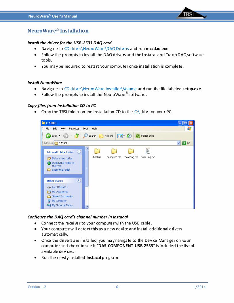
Copy files from Installation CD to PC
Copy the TBSI folder on the ins tallation CD to the C:\ drive on your PC.
Configure the DAQ card’s channel number in Instacal
Connect the receiver to your computer with the USB cable. Your computer will detect this as a new device and ins tall additional drivers
automatically.
Once the drivers are ins talled, you may navigate to the Device Manager on your computer and check to see if “DAS‐COMPONENT‐USB 2533” is included the lis t of available devices .
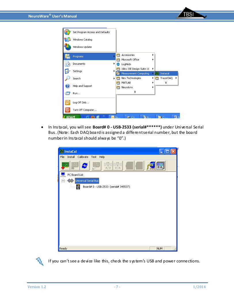
Run the newly installed Instacal program.
NeuroWare© User’s Manual
Version1.2 ‐7‐ 1/2014
In Ins tacal, you will see Board# 0 ‐ USB‐2533 (serial#******) under Universal Serial Bus . (Note: Each DAQ board is assigned a different serial number, but the board number in Ins tacal should always be “0”.)
If you can’t see a device like this, check the system’s USB and power connections.
NeuroWare© User’s Manual
Version1.2 ‐8‐ 1/2014
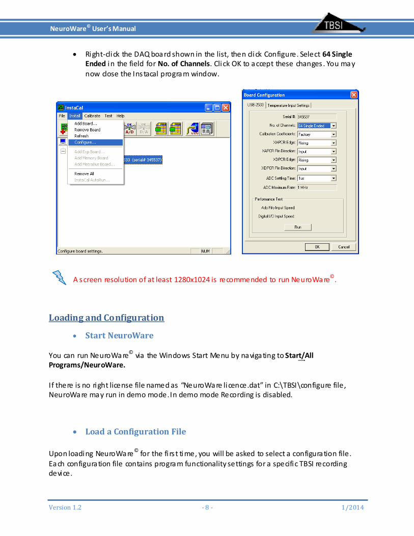
Right‐click the DAQ board shown in the list, then click Configure. Select 64 Single Ended in the field for No. of Channels. Click OK to accept these changes . You may now close the Ins tacal program window.
A screen resolution of at least 1280x1024 is recommended to run NeuroWare©.
LoadingandConfiguration
StartNeuroWare You can run NeuroWare
© via the Windows Start Menu by navigating to Start͢/All Programs/NeuroWare. If there is no right license file named as “NeuroWare li cence.dat” in C:\TBSI\configure file, NeuroWare may run in demo mode. In demo mode Recording is disabled.
LoadaConfigurationFile Upon loading NeuroWare© for the fi rs t time, you will be asked to select a configuration file. Each configuration file contains program functionality settings for a specific TBSI recording device.

NeuroWare© User’s Manual
Version1.2 ‐9‐ 1/2014
Choose the configuration file which matches your data acquisi tion hardware model (ex. a file ending in M32 should be used with a 32 channel M‐Series recording system).
ConfigureNeuroWare© Adjusting Settings in a Configuration File To change and save selected DAQ settings to be loaded in future ins tances of NeuroWare
©, navigate to the Tools menu at the top left of the program, then select Configuration from the drop‐down menu to open the Configuration Dialog. Many settings in the Configuration Dialog are unique to that menu and can’t be accessible in NeuroWare . It is recommended to review all settings in the Configuration Dialog to ensure that each parameter is appropriately defined. Refer to other sections for how to set up those settings that are only accessible in Configuration. Be sure to s top DAQ before opening the configuration dialog.
LoadNewConfig Use this button when you want to load a new configuration file.
NeuroWare© User’s Manual
Version1.2 ‐10‐ 1/2014
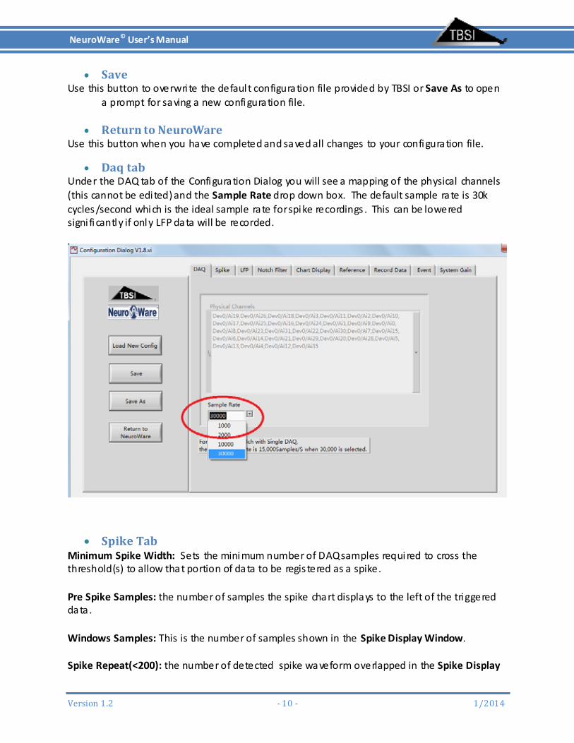
Save Use this button to overwri te the defaul t configuration file provided by TBSI or Save As to open
a prompt for saving a new configuration file.
ReturntoNeuroWare Use this button when you have completed and saved all changes to your configuration file.
Daqtab Under the DAQ tab of the Configuration Dialog you will see a mapping of the physical channels (this cannot be edited) and the Sample Rate drop down box. The default sample rate is 30k cycles/second which is the ideal sample rate for spike recordings . This can be lowered signi ficantly if only LFP data will be recorded.
SpikeTabMinimum Spike Width: Sets the minimum number of DAQ samples required to cross the threshold(s) to allow that portion of data to be regis tered as a spike. Pre Spike Samples: the number of samples the spike chart displays to the left of the triggered data . Windows Samples: This is the number of samples shown in the Spike Display Window. Spike Repeat(<200): the number of detected spike waveform overlapped in the Spike Display

NeuroWare© User’s Manual
Version1.2 ‐11‐ 1/2014
Window Spike Filter: A low cutoff frequency of more than 100Hz is recommended to remove the low‐frequency component signal . Taps determine the order of the digi tal fil ter. Selecting an odd number larger than 101 is recommended. Threshold Selection: There are two threshold are available to set up the threshold levels.
Threshold1: Only Threshold1 is enabled. Threshold2: Only Threshold2 is enabled. Threshold1 and Threshold2: Both Threshold1 and Threshold2 are enabled.
Only Spikes crossing Threshold1 and Threshold2 will be detected. Threshold1 or Threshold2: Both Threshold1 and Threshold2 are enabled.
Spike crossing either Threshold1 or Threshold2 will be detected. Trigger Oder: (only available when Threshold1 and Threshold2 is selected in Threshold Selection ) Threshold Level: This displays the ampli tude in uV. That each channels Threshold is set at.
LFPTabLFP sample rate: This is the sample rate at which LFP signal is acquired and displayed. Since LFPs do not require as high a sample rate as Spike recordings this tab gives you the option to sample LFPs at a much lower sample rate.
LFP filter: A lowpass filter is used to remove unwanted high frequency noise and signals. Adjust filter bandwidths by changing low cut frequency. The high cut frequency will be ignored when you use the lowpass filter. The “taps” is the order of digital filter. An odd number more than 101 is recommended. The “window” option affects the digital filter performance. If the “Click to enable” button is on, the current filter is used. If the “Click to enable” button is of”, the current filter is off.

NeuroWare© User’s Manual
Version1.2 ‐12‐ 1/2014
NotchFilterTabA Notch Filter can be applied to the raw data of all channels from DAQ card. The default cutoff frequencies are set around 60Hz rejection. It is recommended to review the Notch Filter Settings under the Filters tab before setting up spike triggering conditions and browsing spike and LFP waveform.
Filter Selection: The default filter is Butterworth filter.
ChartDisplayTabDisplay Mode/Strip Display Mode: Strip Chart: displays the selected channel ’s data as a constantly scrolling s tream Scope Chart: refreshes enti re window with new data after chart is filled Sweep Chart: same as scope chart, but continues to display previous data until it is overwri tten by newer data Multiple chs Window Config: Window Width (ms): adjusts the maximum amount of x‐data displayed at a time Display Zoom: increases or decreases the zoom of the Y‐axis. Strip Window config: Data Select Raw Data: displays the incoming raw data (unfil tered) Spike Waveform: displays the selected channel with spike fil ter settings applied LFP Waveform: displays the selected channel with LFP fil ter settings applied
ReferenceTabNeuroware is set defaul t to reference from the headstage “AGND” which should be connected to an animal ground implant. If you wish to ins tead use differential referencing from a speci fic recorded channel click the oval Enable Referencing button. When enabled, the green light on the oval button will be lit. Reference Channel Setting: This function is also available through the Reference Tab in Neuroware . For each channel you are able to set up separate reference channels for Spike data and LFP data recordings.
RecordDataTabFile save path: The defaul t file path is “C:\TBSI\recording file. However, i t is highly recommended that you change this path to an appropriately sized SATA 3 Solid state storage drive or high speed RAID array. Recording Data Selection: You can select to record simultaneous spike waveform, LFP, and continuous raw data by checking associated boxes . Spike chain is checked by defaul t. Comments: You can add additional information to recording files before starting record. Recording time: Use this box to set the duration (in seconds) of your recordings . Recorded channel setting: Set up if the channel is recorded and select what type of continuous data are selected.
NeuroWare© User’s Manual
Version1.2 ‐13‐ 1/2014
RecordDataTabMax Event num: This is the max number of events showed in Event Table. For example, if we set it up to 50, the 51st event will be displayed on the fi rst line of Event Table.
Min Event Interval: This box sets the minimum time expected for an event to take place. Default this is set to 100mS. If more than one event input is to be recorded this needs to be set to 1.
Event Definition Table: Use this table to change the definition of the events recorded.
SystemGainTabSystem Gain: This displays the gain applied to the signal acquired by the DAQ. This cannot be changed.
NeuroWare© User’s Manual
Version1.2 ‐14‐ 1/2014
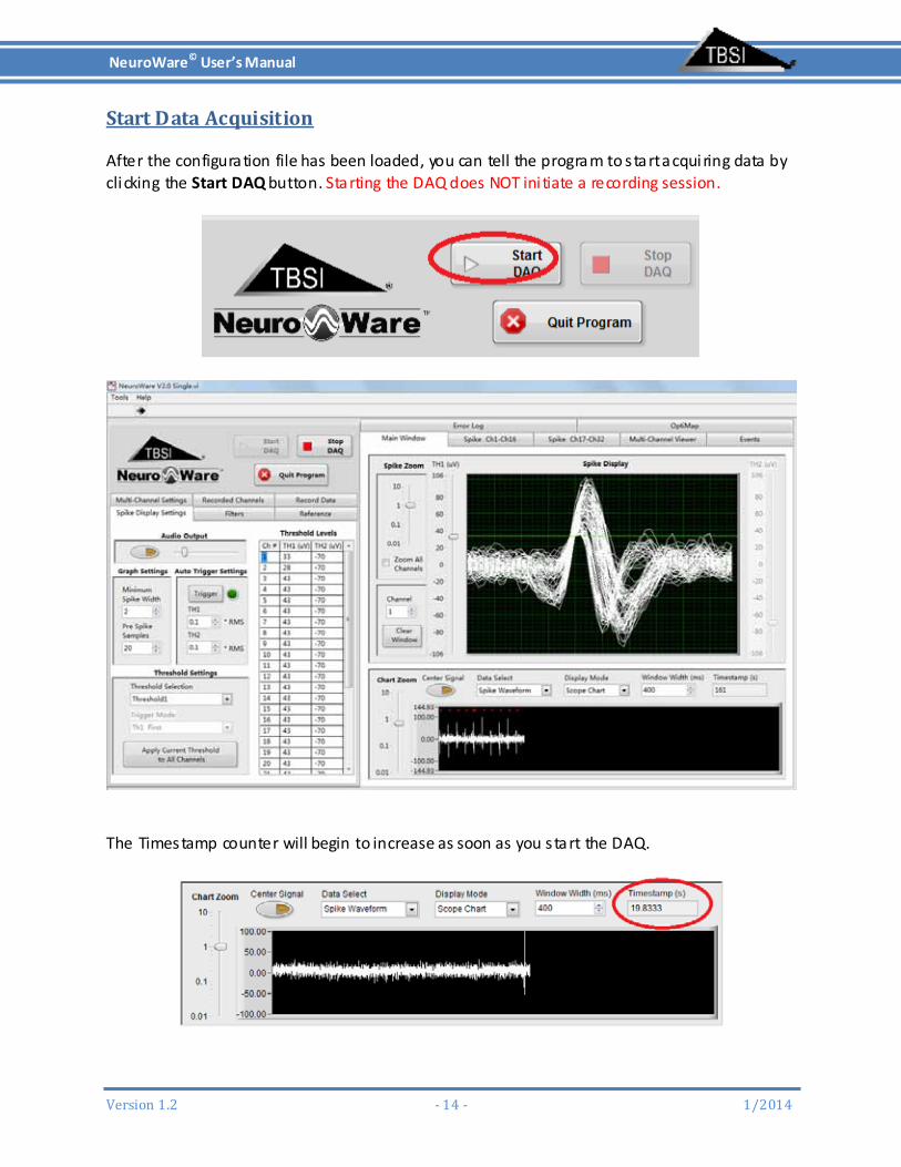
StartDataAcquisition
After the configuration file has been loaded, you can tell the program to start acquiring data by clicking the Start DAQ button. Starting the DAQ does NOT ini tiate a recording session.
The Timestamp counter will begin to increase as soon as you start the DAQ.

NeuroWare© User’s Manual
Version1.2 ‐15‐ 1/2014
The raw data acquired by the DAQ will then be processed by NeuroWare©’s digi tal spike and LFP fil ters (if they are enabled under the Filters tab). NeuroWare
©’s spike detection functions utilize the data generated by the designated spike fil ter settings . Only one spike filtered channel can be displayed at a time within the Main Window tab. Refer to the settings provided under the Spike Display Settings tab to configure spike thresholding and trigger conditions for each channel as they are displayed in the Main Window. Use the Channel counter to the left of the Spike Display chart under the Main Window tab to cycle through your system’s available channels . Navigate to the Spike Ch1‐Ch16, Spike Ch17‐Ch32, Spike Ch33‐Ch48, and Spike Ch49‐Ch64 tabs to simultaneously view those channels’ Main Window data streams. This is a good way to quickly determine which channels s till require trigger/zoom/filter adjustments. Clicking the Clear Window button will clear the Spike Display and the corresponding Spike Ch tab chart of all detected spike waveforms. This is for viewing purposes only and will not delete any recorded data .
NotchFilter Notch Filter can be applied to the raw data of all channels from DAQ card. It is recommended to review the Notch Filter Settings under the Filters tab before setting up spike triggering conditions and browsing spike and LFP waveform. NeuroWare
© defaul ts the notch fil ter enabled(Yellow) as shown below. You can choose to disable i t by clicking the Enable button. NeuroWare© defaul ts the fil ter settings to the ones shown below. You can adjust the high, low cutoff frequencies and order any time. Note: You may adjust the cutoff frequency based on local power line frequency

NeuroWare© User’s Manual
Version1.2 ‐16‐ 1/2014

NeuroWare© User’s Manual
Version1.2 ‐17‐ 1/2014
SpikeDetectionandDisplay
SpikeFilter It is recommended to review the Spike Filter Settings under the Filters tab before setting up spike triggering conditions . NeuroWare
© defaul ts the fil ter settings to the ones shown below. You can adjust the high and low cutoff frequencies any time before or during a recording. A low cutoff frequency of more than 100Hz is recommended to remove the low‐frequency component signal . Taps determine the order of the digi tal filter. Selecting an odd number larger than 101 is recommended.

NeuroWare© User’s Manual
Version1.2 ‐18‐ 1/2014
SpikeTriggering Once you have finalized your Spike Filter Settings , you can begin setting up the spike trigger conditions , found within the Spike Display Settings tab.
AudioOutput
If any spike is detected in the current selected channel, you will hear “pu” if Audio output is enabled. Use the oval button to enable/disable audio output. The audio corresponds to the channel currently displayed in the Spike Display chart. Drag the slider to adjust the volume output.

NeuroWare© User’s Manual
Version1.2 ‐19‐ 1/2014
GraphSettings
Note: Windows Samples and Spike Repeat(<200) are only accessible in Configuration Dialog and you can’t change them when DAQ is going.
Minimum Spike Width: the minimum number of DAQ samples required to cross the threshold(s) to allow that portion of data to be regis tered as a spike Pre Spike Samples: the number of samples the spike chart displays to the left of the triggered data Windows Samples: the number of samples the Spike Display Window.
Spike Repeat(<200): the number of detected spike waveform overlapped in the Spike Display Window
AutoTriggerSettings
Trigger Settings are located in Spike Display Settings tab
Auto triggering applies to all channels and will take a few seconds to complete as i t processes samples from the current channel ’s data. Clicking the Auto trigger button will automatically set up trigger threshold(s) for every available channel , which can be useful for quickly identifying
NeuroWare© User’s Manual
Version1.2 ‐20‐ 1/2014
possible spikes on any given channel . This function sets the spike threshold(s) by calculating each channel’s root mean square (RMS) voltage and multiplying i t by a user‐defined rational number. If you wish to use auto triggering with both available thresholds (TH1 and TH2), you must enable them by selecting Threshold1 and Threshold2 from the dropdown list in the Threshold Selection of Threshold Settings section found in the same tab.
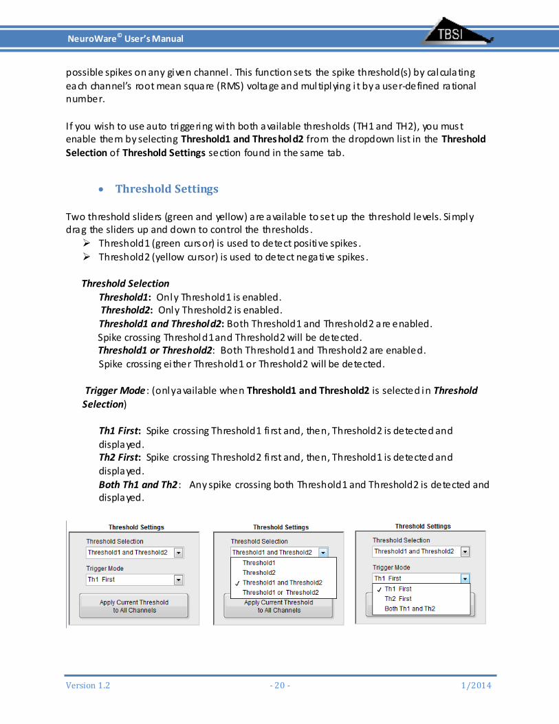
ThresholdSettings Two threshold sliders (green and yellow) are available to set up the threshold levels. Simply drag the sliders up and down to control the thresholds . Threshold1 (green cursor) is used to detect positive spikes . Threshold2 (yellow cursor) is used to detect negative spikes .
Threshold Selection
Threshold1: Only Threshold1 is enabled. Threshold2: Only Threshold2 is enabled. Threshold1 and Threshold2: Both Threshold1 and Threshold2 are enabled. Spike crossing Threshold1 and Threshold2 will be detected. Threshold1 or Threshold2: Both Threshold1 and Threshold2 are enabled. Spike crossing either Threshold1 or Threshold2 will be detected.
Trigger Mode : (only available when Threshold1 and Threshold2 is selected in Threshold Selection)
Th1 First: Spike crossing Threshold1 fi rst and, then, Threshold2 is detected and displayed. Th2 First: Spike crossing Threshold2 fi rst and, then, Threshold1 is detected and displayed. Both Th1 and Th2: Any spike crossing both Threshold1 and Threshold2 is detected and displayed.
NeuroWare© User’s Manual
Version1.2 ‐21‐ 1/2014
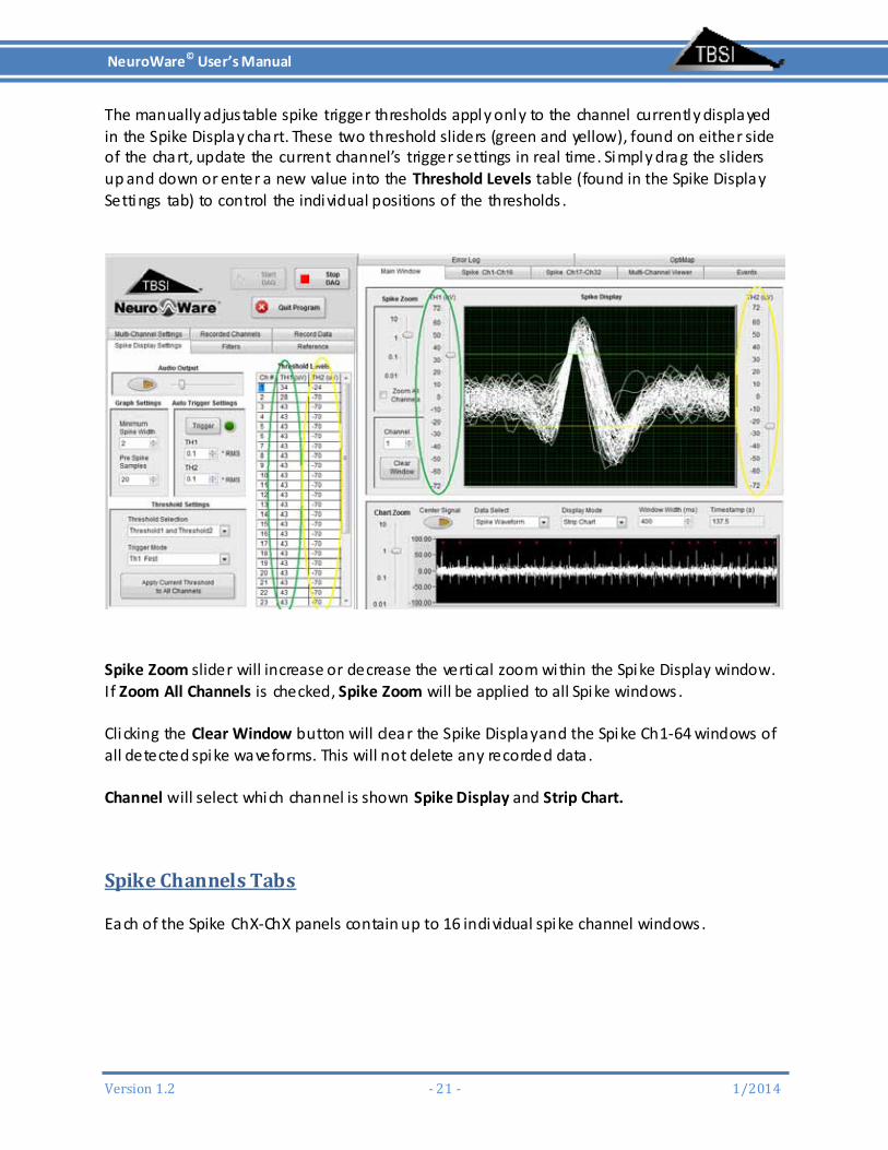
The manually adjustable spike trigger thresholds apply only to the channel currently displayed in the Spike Display chart. These two threshold sliders (green and yellow), found on either side of the chart, update the current channel’s trigger settings in real time. Simply drag the sliders up and down or enter a new value into the Threshold Levels table (found in the Spike Display Settings tab) to control the individual positions of the thresholds .
Spike Zoom slider will increase or decrease the vertical zoom within the Spike Display window. If Zoom All Channels is checked, Spike Zoom will be applied to all Spike windows. Clicking the Clear Window button will clear the Spike Display and the Spike Ch1‐64 windows of all detected spike waveforms. This will not delete any recorded data . Channel will select which channel is shown Spike Display and Strip Chart.
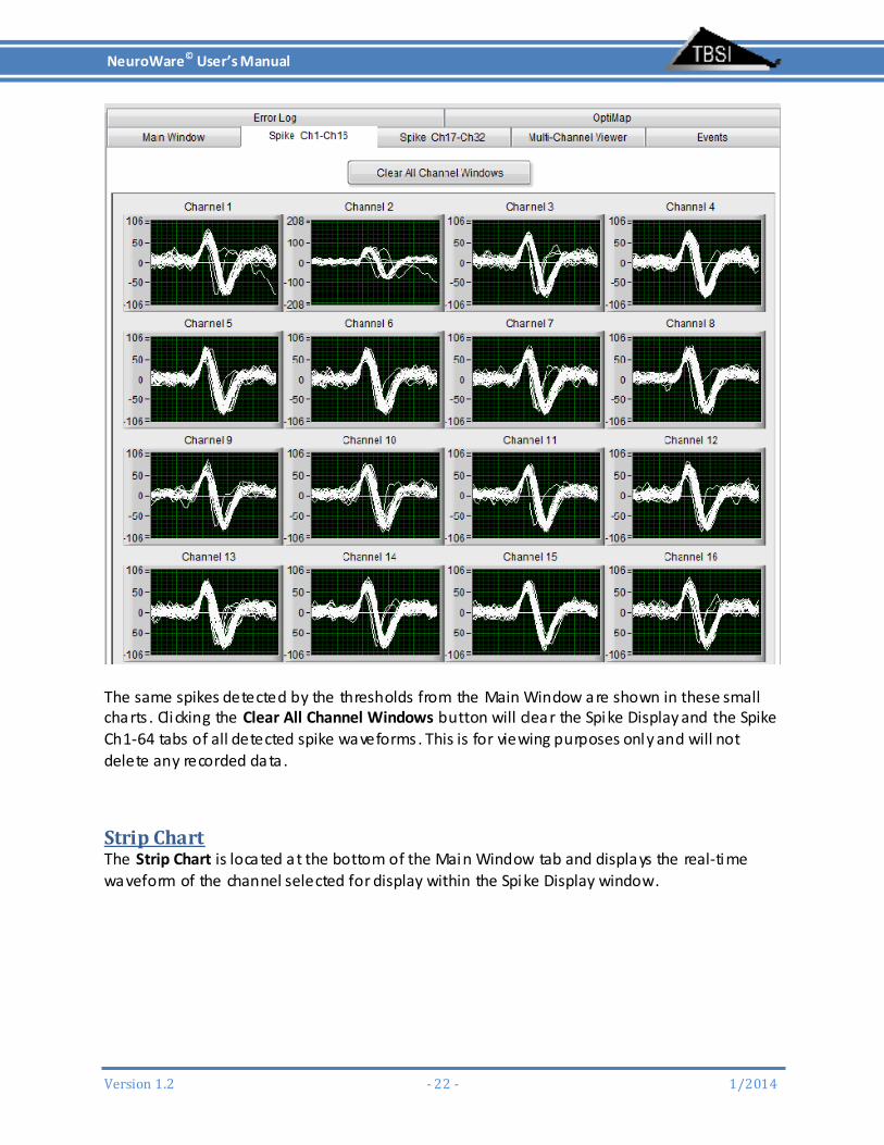
SpikeChannelsTabs Each of the Spike ChX‐ChX panels contain up to 16 individual spike channel windows.
NeuroWare© User’s Manual
Version1.2 ‐22‐ 1/2014
The same spikes detected by the thresholds from the Main Window are shown in these small charts . Clicking the Clear All Channel Windows button will clear the Spike Display and the Spike Ch1‐64 tabs of all detected spike waveforms. This is for viewing purposes only and will not delete any recorded data .
StripChartThe Strip Chart is located at the bottom of the Main Window tab and displays the real‐time waveform of the channel selected for display within the Spike Display window.

NeuroWare© User’s Manual
Version1.2 ‐23‐ 1/2014
Center Signal Click the oval Center Signal button to automatically center the incoming signal to 0V. Data Select Raw Data: displays the incoming raw data (unfil tered) Spike Waveform: displays the selected channel with spike fil ter settings applied LFP Waveform: displays the selected channel with LFP fil ter settings applied Display Mode Strip Chart: displays the selected channel ’s data as a constantly scrolling s tream Scope Chart: refreshes enti re window with new data after chart is filled Sweep Chart: same as scope chart, but continues to display previous data until it is overwri tten by newer data Window Width (ms): adjusts the maximum amount of x‐data displayed at a time Chart zoom: increases or decreases the zoom of the Y‐axis.
LFPWaveformLFP waveform can be viewed by Strip Chart or Multi‐Channels Viewer when selecting the right data type. It is recommended to review the Fil ter tab before viewing LFP. NeuroWare defaul ts the filter settings to the ones shown as follows .
NeuroWare© User’s Manual
Version1.2 ‐24‐ 1/2014
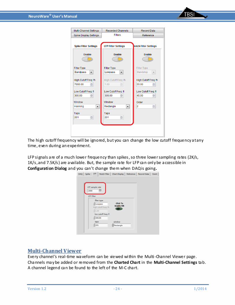
The high cutoff frequency will be ignored, but you can change the low cutoff frequency at any time, even during an experiment. LFP signals are of a much lower frequency than spikes , so three lower sampling rates (2K/s, 1K/s , and 7.5K/s ) are available. But, the sample rate for LFP can only be accessible in Configuration Dialog and you can’t change them when DAQ is going.
Multi‐ChannelViewerEvery channel ’s real‐time waveform can be viewed within the Multi ‐Channel Viewer page. Channels may be added or removed from the Charted Chart in the Multi‐Channel Settings tab. A channel legend can be found to the left of the M‐C chart.

NeuroWare© User’s Manual
Version1.2 ‐25‐ 1/2014
Charted Channels: Select the channels that are displayed in Multi‐Channel by Add or Remove buttons Center Signal Click the oval Center Signal button to automatically center the incoming signal to 0V. Continuous Data Type Raw Data: displays the incoming raw data (unfil tered) Spike Waveform: displays the selected channel with spike fil ter settings applied LFP Waveform: displays the selected channel with LFP fil ter settings applied Window Width (ms): adjusts the maximum amount of x‐data displayed at a time Zoom: increases or decreases the zoom of the Y‐axis . Interval: adjust the interval among the channels of Y‐axis.

NeuroWare© User’s Manual
Version1.2 ‐26‐ 1/2014
ChannelReferenceUnder the Reference tab, click the oval Enable Referencing button to enable channel referencing. These settings may be adjusted during a recording if necessary, and any changes will be reflected in real time. When channel referencing is enabled, the selected Reference Channel (within the Reference Settings box) will be applied to the channel currently being viewed in the Spike Display chart. Click the Apply Current Reference to All Channels button to change every channel ’s reference channel or manually enter any channel number into the Channel Reference Chart to change reference channel for individual channel . So, you are able to select di fferent channel as reference channel. Note: If Reference is enabled, both Spike and LFP fil ter will function based on referenced data .
NeuroWare© User’s Manual
Version1.2 ‐27‐ 1/2014
RecordData
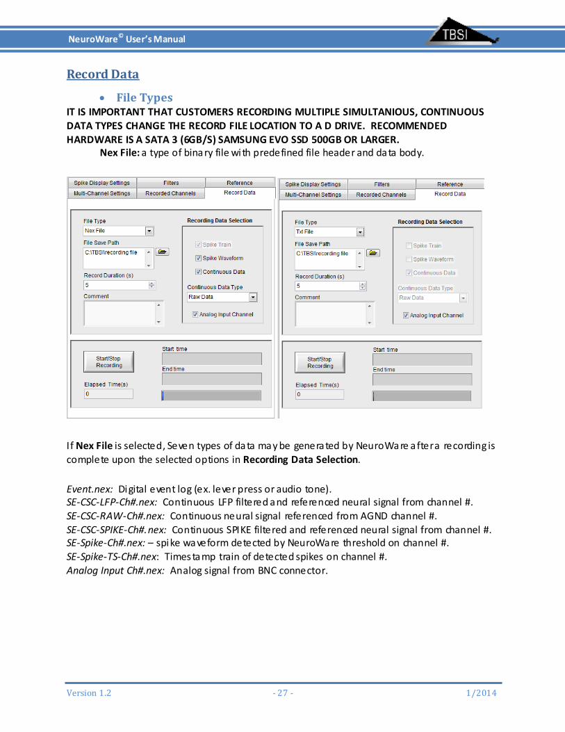
FileTypesIT IS IMPORTANT THAT CUSTOMERS RECORDING MULTIPLE SIMULTANIOUS, CONTINUOUS DATA TYPES CHANGE THE RECORD FILE LOCATION TO A D DRIVE. RECOMMENDED HARDWARE IS A SATA 3 (6GB/S) SAMSUNG EVO SSD 500GB OR LARGER. Nex File: a type of binary file with predefined file header and data body.
If Nex File is selected, Seven types of data may be generated by NeuroWare after a recording is complete upon the selected options in Recording Data Selection.
Event.nex: Digital event log (ex. lever press or audio tone). SE‐CSC‐LFP‐Ch#.nex: Continuous LFP filtered and referenced neural signal from channel #. SE‐CSC‐RAW‐Ch#.nex: Continuous neural signal referenced from AGND channel #. SE‐CSC‐SPIKE‐Ch#.nex: Continuous SPIKE filtered and referenced neural signal from channel #. SE‐Spike‐Ch#.nex: – spike waveform detected by NeuroWare threshold on channel #. SE‐Spike‐TS‐Ch#.nex: Timestamp train of detected spikes on channel #. Analog Input Ch#.nex: Analog signal from BNC connector.

NeuroWare© User’s Manual
Version1.2 ‐28‐ 1/2014
FileSavePathNeuroWare defaul ts the file path for recorded file to C:\TBSI\recording file. Change the file path before start recording if needed.
RecordingDataSelection If Nex File is selected, Spike Train is selected by defaul t. Spike Waveform, Continuous Data and Analog Input Channel are ready for being selected. If Continuous Data is checked, you get a chance to select what kind of data is recorded. Raw Data: the incoming raw data (unfil tered) Spike Waveform: data with spike filter settings applied LFP Waveform: data with LFP fil ter settings applied Analog Input Channel i s particularly for BNC analog input.
CommentsAny information less than 256 char typed in Comment will be not only saved in Nex file, but also in “Note.txt” file which is in the same folder as Nex or Txt file.
RecordedChannelAll channels will be recorded by defaul t. You can add or remove the channel by clicking Remove or Add button in Recorded Channels tab.

NeuroWare© User’s Manual
Version1.2 ‐29‐ 1/2014
RecordedFileNameBy default, the Nex files are named as SE‐CSC‐Ch#_.nex/ SE‐Spike‐Ch#_.nex/ SE‐Spike‐TS‐Ch#_. If you want to change them, you can go to Configuration Dialog to add suffix to each channel. For example, i f you type in Neuron1 in Ch1 and Neuron2 in Ch2, the recorded file name will be SE‐CSC‐Ch1_Neuron1.nex.

NeuroWare© User’s Manual
Version1.2 ‐30‐ 1/2014
Start/StopRecordingIt is recommended to review the Charted Channel, File type, Recording Data Selection and Record Duration before recording. Record Duration is required to be a number with the unit Second, which means you have to convert the recording time to time with the unit second. Click Start/Stop recording button to start recording. The recording process can be monitored either by Elapsed Time or by progress bar. Whenever you want to stop recording before Record Duration run out, you can click Start/Stop recording.
HowtoLoadNexFileThe .nex files generated by NeuroWare can be loaded directly into NeuroExplorer for analysis. These binary files can also be loaded into Matlab – please refer to the Appendix for details.
HowtoLoadTextDataThe .txt file generated by NeuroWare is an ASCII file which can be loaded directly into MS Excel .

NeuroWare© User’s Manual
Version1.2 ‐31‐ 1/2014
EventsNeuroWare can detect the status change of up to 24 digi tal lines within the ADC DAQ board. Digi tal level changes (such as 0→1 or 1→0) are thought of as an event and can be displayed and recorded in NeuroWare. *The ADC cannot support simultaneous changes on different channels. For this reason TBSI does not support the use of more than one Digital Data input at a time.
DigitalLinesConnectionAll 24 digi tal lines are accessible with a 68‐pin SCSI connector. A couple of digi tal lines are also accessible with BNC connector. Connect the digi tal signals of interest to your system via pins A0‐A7,B0‐B7,C0‐C7 (shown below).
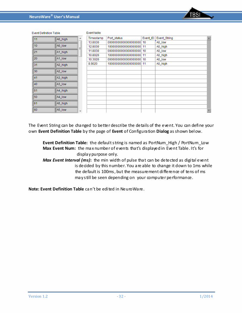
DigitalEventsDigi tal level changes of 24 digi tal lines are defined as di fferent Event ID within NeuroWare (see table and image below). Any changes to the event variables A0→A7,B0→B7 , C0→C7, will be shown in the Event Table. For example, if the digi tal level of the A0 line changes , you will see an event in the Event Table as shown below.
NeuroWare© User’s Manual
Version1.2 ‐32‐ 1/2014
The Event String can be changed to better describe the details of the event. You can define your own Event Definition Table by the page of Event of Configuration Dialog as shown below. Event Definition Table: the defaul t s tring is named as PortNum_High / PortNum_Low Max Event Num: the max number of events that’s displayed in Event Table. It’s for display purpose only. Max Event Interval (ms): the min width of pulse that can be detected as digi tal event is decided by this number. You are able to change it down to 1ms while the default is 100ms, but the measurement di fference of tens of ms may s till be seen depending on your computer performance. Note: Event Definition Table can’t be edited in NeuroWare.

NeuroWare© User’s Manual
Version1.2 ‐33‐ 1/2014
EventFileDigi tal event information s tored within the event.nex file (shown below) can be loaded into NeuroExplorer.

NeuroWare© User’s Manual
Version1.2 ‐34‐ 1/2014
AnalogInputChannel
An analog input channel separated from the other neural channels is provided for custom purpose. The TTL waveform up to +/‐ 5V can be acquired by DAQ directly at up to 30kS/s . Also, no fil ter will be applied to this channel .

NeuroWare© User’s Manual
Version1.2 ‐35‐ 1/2014
ErrorLogWindow
The Error Log window helps trace problems that have occurred within NeuroWare. Please consult this page if you experience problems during recording. All errors are logged into a .txt file located in the directory speci fied within the Error Log File Path field.
QuitNeuroWareTo quit the program, click the Quit Program button which is located beneath the Start DAQ button or close panel directly. It’s recommended to check if you like to save the current setting to the current config file or save as a new config file by Configuration Dialog (Tools/Configuration)

NeuroWare© User’s Manual
Version1.2 ‐36‐ 1/2014
Click OK in the next dialog box to confi rm that you want to quit.
Readingfiles
LoadDataintoNeuroExplorerLoad the NeuroExplorer program, navigate to File→Open and open SE‐CSC‐Ch#.nex (where # is the channel of your choice).

NeuroWare© User’s Manual
Version1.2 ‐37‐ 1/2014
NeuroWare© User’s Manual
Version1.2 ‐38‐ 1/2014
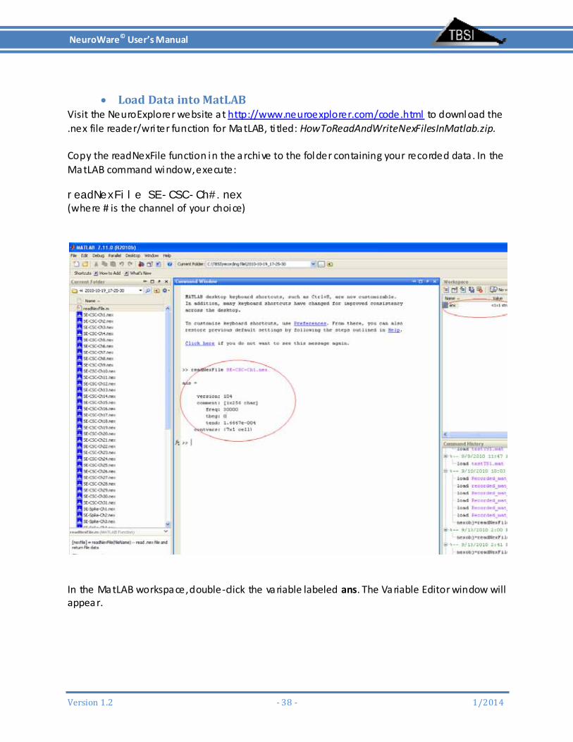
LoadDataintoMatLABVisit the NeuroExplorer website at http://www.neuroexplorer.com/code.html to download the .nex file reader/wri ter function for MatLAB, ti tled: HowToReadAndWriteNexFilesInMatlab.zip. Copy the readNexFile function in the archive to the folder containing your recorded data . In the MatLAB command window, execute: readNexFile SE-CSC-Ch#.nex (where # is the channel of your choice)
In the MatLAB workspace, double‐click the variable labeled ans. The Variable Editor window will appear.
NeuroWare© User’s Manual
Version1.2 ‐39‐ 1/2014
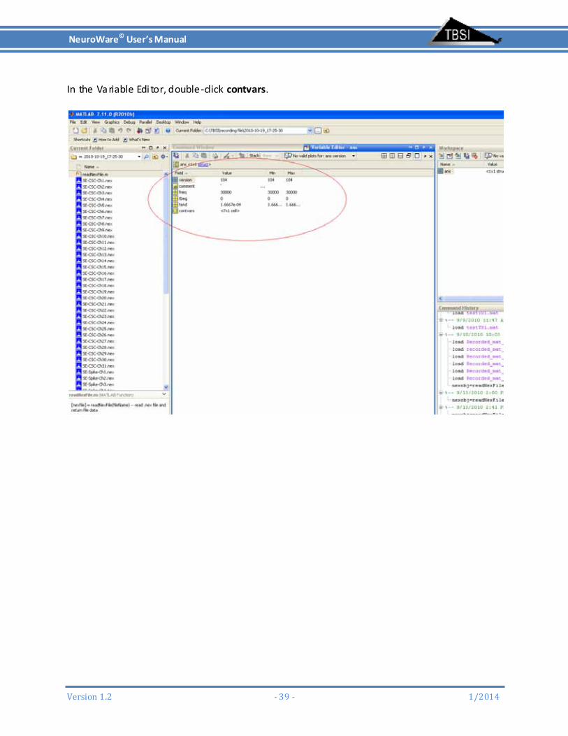
In the Variable Editor, double‐click contvars.
NeuroWare© User’s Manual
Version1.2 ‐40‐ 1/2014
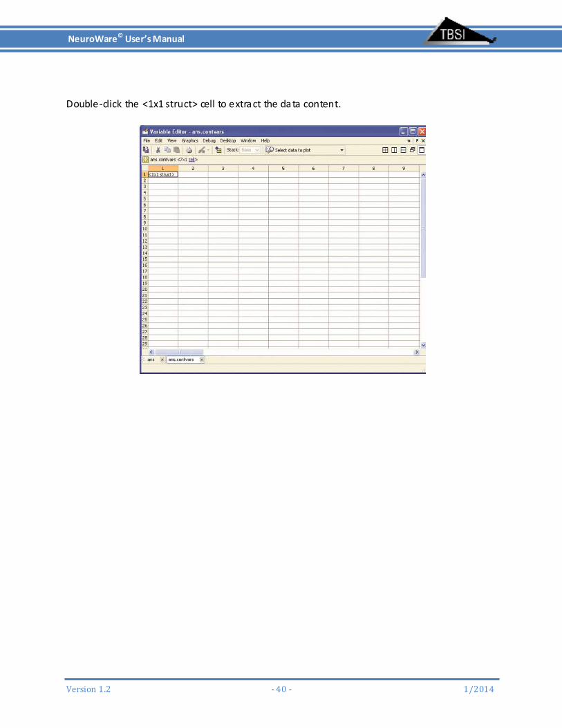
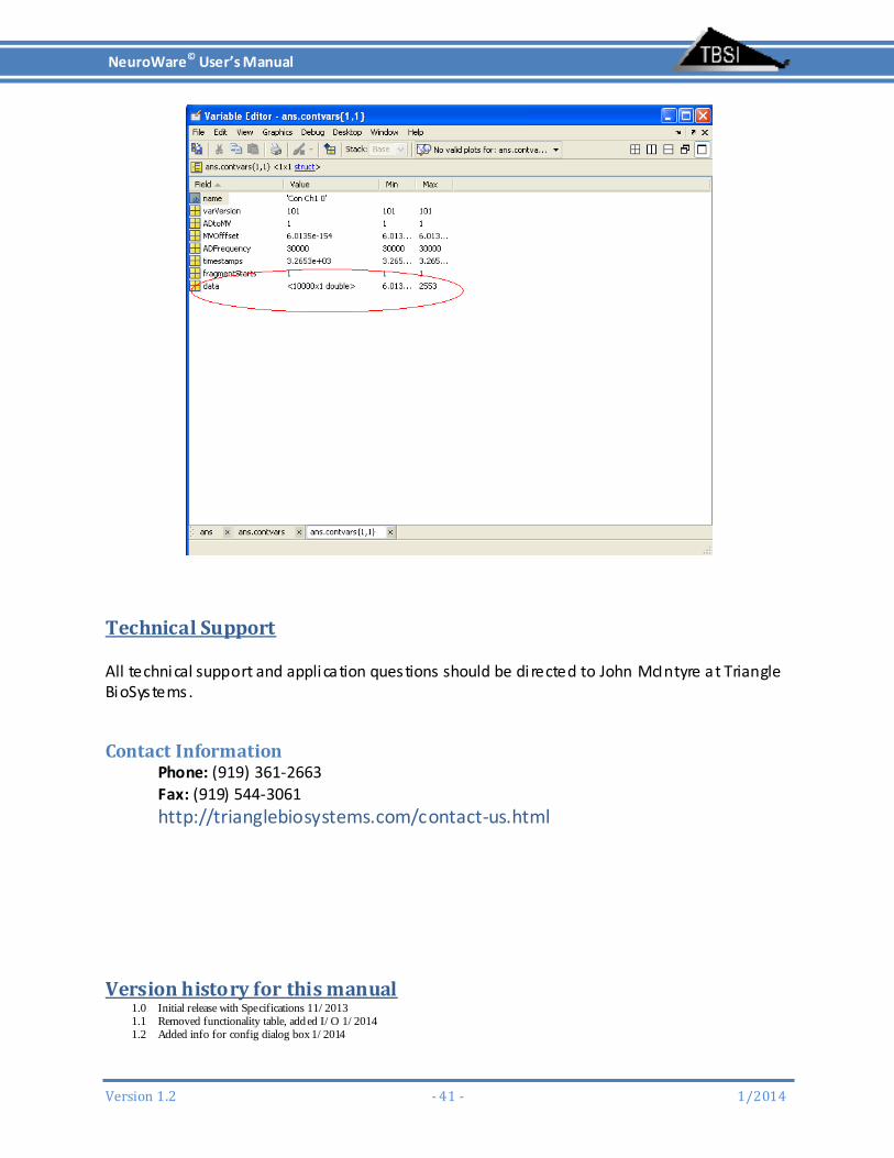
Double‐click the <1x1 struct> cell to extract the data content.
NeuroWare© User’s Manual
Version1.2 ‐41‐ 1/2014
TechnicalSupport All technical support and application questions should be directed to John McIntyre at Triangle BioSystems.
ContactInformationPhone: (919) 361‐2663 Fax: (919) 544‐3061
http://trianglebiosystems.com/contact‐us.html
Versionhistoryforthismanual1.0 Initial release with Specifications 11/2013 1.1 Removed functionality table, add ed I/O 1/2014 1.2 Added info for config dialog box 1/2014