imageteam™ 4400/4700 2d series user’s guide …...user’s guide user’s guide user’s guide...
TRANSCRIPT

™
Use
r’s
Gui
de U
ser’
s G
uid
e U
ser’
s G
uide
Use
r’s
Gu
ide
Use
r’s
Gui
de U
ser’
s G
uid
e U
ser’
s G
uide
IMAGETEAM™ 4400/47002D SeriesHand Held Imager

Statement of Agency Compliance
This device complies with part 15 of the FCC Rules. Operation is subject to the following two conditions: (1) this device may not cause harmful interference, and (2) this device must accept any interference received, including interference that may cause undesired operation.
FCC Class B Compliance Statement
This equipment has been tested and found to comply with the limits for a Class B digital device pursuant to part 15 of the FCC Rules. These limits are designed to provide reasonable protection against harmful interference in a residential installation. This equipment generates, uses, and can radiate radio frequency energy and, if not installed and used in accordance with the instructions, may cause harmful interference to radio communications. However, there is no guarantee that interference will not occur in a particular installation. If this equipment does cause harmful interference to radio or television reception, which can be determined by turning the equipment off and on, the user is encouraged to try to correct the interference by one or more of the following measures:
• Reorient or relocate the receiving antenna.• Increase the separation between the equipment and receiver.• Connect the equipment into an outlet on a circuit different from that to
which the receiver is connected.• Consult the dealer or an experienced radio or television technician for
help.Caution: Any changes or modifications made to this device that are not expressly approved by Welch Allyn Data Collection, Inc. may void the user’s authority to operate the equipment.Note: To maintain compliance with FCC Rules and Regulations, cables connected to this device must be shielded cables, in which the cable shield wire(s) have been grounded (tied) to the connector shell.
Canadian Notice
This equipment does not exceed the Class B limits for radio noise emissions as described in the Radio Interference Regulations of the Canadian Department of Communications.Le present appareil numerique n’emet pas de bruits radioelectriques depassant les limites applicables aux appareils numeriques de la classe B prescrites dans le Reglement sur le brouillage radioelectrique edicte par le ministere des Communications du Canada.
CDRH Laser Safety Statement
This product complies with US DHHS 21 CFR J Part 1040.10. This product is a CLASS II LASER PRODUCT with a maximum output of 1.0 mW at 670 nanometers and continuous wave.
EN 60825-1 Laser Safety Statement
This product is classified as a CLASS 2 LASER PRODUCT with a maximum output of 1.0 mW at 670 nanometers per EN 60825-1:1994, Issue 2, June 1997.

The CE mark on the product indicates that the system has been tested to and conforms with the provisions noted within the 89/336/EEC Electromagnetic Compatibility Directive and the 73/23/EEC Low Voltage Directive.
For further information please contact:Welch Allyn Ltd.Block 1, Bracken Business ParkSandyford, Co. DublinIrelandorWelch Allyn Ltd.1st FloorDallam Court Dallam LaneWarrington, Cheshire WA2 7LTEngland
Welch Allyn Data Collection, Inc. shall not be liable for use of our product with equipment (i.e., power supplies, personal computers, etc.) that is not CE marked and does not comply with the Low Voltage Directive.
Patents
The IMAGETEAM 4400/4700 products are covered by one or more of the following U.S. Patents: 5,420,409, 5,780,834, 5,723,853; 5,723,868; 5,825,006; 5,900,613; 5,929,418. Other U.S. and foreign patents pending.Scan on Demand is covered by the following patent: 5,463,214.Image Sensor Containment System is covered by the following patent: 5,838,495.
Disclaimer
Welch Allyn Data Collection, Inc. reserves the right to make changes in specifications and other information contained in this document without prior notice, and the reader should in all cases consult Welch Allyn Data Collection, Inc. to determine whether any such changes have been made. The information in this publication does not represent a commitment on the part of Welch Allyn Data Collection, Inc.Welch Allyn Data Collection, Inc. shall not be liable for technical or editorial errors or omissions contained herein; nor for incidental or consequential damages resulting from the furnishing, performance, or use of this material.This document contains proprietary information which is protected by copyright. All rights are reserved. No part of this document may be photocopied, reproduced, or translated into another language without the prior written consent of Welch Allyn Data Collection, Incorporated. 1999-2000 Welch Allyn Data Collection, Inc. All rights reserved.
Welch Allyn Data Collection, Inc. Web Address: http://dcd.welchallyn.com


Chapter 1 - Introduction and Installation
About the Hand-Held 2D Imager ......................................... 1-1Unpacking the Imager........................................................... 1-2IT4400 Imager Identification................................................ 1-3IT4700 Imager Identification................................................ 1-4Laser and LED Safety........................................................... 1-5Connecting the Scanner When Powered by Host
(Keyboard Wedge)............................................................. 1-6Reading Techniques.............................................................. 1-7Depth of Field Charts............................................................ 1-8
Chapter 2 - Programming
Introduction........................................................................... 2-1Reset Factory Settings .......................................................... 2-2Status Check ......................................................................... 2-2All Symbologies ................................................................... 2-3Revision Selections............................................................... 2-3Terminal Interface ................................................................ 2-4Supported Terminals Chart ................................................... 2-5Keyboard Country ................................................................ 2-6Keyboard Style ..................................................................... 2-7Keyboard Modifiers.............................................................. 2-8Keyboard Function Relationships......................................... 2-9Connecting the Scanner to a Serial Port ............................. 2-10Communication Settings..................................................... 2-11
Parity ............................................................................ 2-11Baud Rate ..................................................................... 2-12Word Length Data Bits ................................................ 2-13Word Length Stop Bits................................................. 2-13Hardware Flow Control................................................ 2-14Software Flow Control ................................................. 2-14Serial Triggering .......................................................... 2-15
Power Saving Mode............................................................ 2-16Power Hold Mode............................................................... 2-16
i

LED Power Level................................................................2-17LED Flashing ......................................................................2-17Aimer Delay ........................................................................2-18Aimer Timeout ....................................................................2-18Aimer Interval ..................................................................... 2-19AutoTrigger......................................................................... 2-20Scan Stand...........................................................................2-20
Scan Stand LED Intensity.............................................2-20Scan Stand Lights .........................................................2-21
Presentation Mode...............................................................2-21Presentation Reread Delay............................................2-21Presentation Default .....................................................2-21Presentation Aimer .......................................................2-22
Zoom ...................................................................................2-22Zoom Placement.................................................................. 2-23Beeper Volume....................................................................2-24Power Up Beeper ................................................................2-24Output Sequence Beeper .....................................................2-24Beep On Decode ................................................................. 2-25
Beeper Default.............................................................. 2-25Intercharacter, Interfunction,
and Intermessage Delays .................................................. 2-26Intercharacter Delay ....................................................2-26Interfunction Delay ...................................................... 2-27Intermessage Delay ...................................................... 2-28
Prefix/Suffix Overview.......................................................2-29Adding a Prefix or Suffix .............................................2-30Add a Carriage Return Suffix to All Symbologies ......2-31Add a Code I.D. Prefix to All Symbologies ................ 2-31Add an AIM I.D. Prefix to All Symbologies ............... 2-31Prefix Entries ................................................................2-32Suffix Entries................................................................2-32
Symbology Chart ................................................................2-33Decimal to Hex to ASCII Conversion Chart....................... 2-34
ii

Data Format Editor Overview .............................................2-35Format Editor Commands.............................................2-36Data Format Editor .......................................................2-38Data Formatter ..............................................................2-39Require Data Format.....................................................2-39Show Data Formats.......................................................2-39Alternate Data Formats.................................................2-40
Output Sequence Overview.................................................2-41Require Output Sequence .............................................2-43Output Sequence Editor ................................................2-44
Multiple Symbols ................................................................2-45No Read...............................................................................2-45Print Weight ........................................................................2-46
Chapter 3 - Symbologies
Introduction ...........................................................................3-1Codabar .................................................................................3-2
Start/Stop Characters ......................................................3-2Message Length ..............................................................3-2Check Character..............................................................3-3
Code 39..................................................................................3-4Start/Stop Characters ......................................................3-4Message Length ..............................................................3-4Full ASCII.......................................................................3-5Check Character..............................................................3-6
Interleaved 2 of 5...................................................................3-7Message Length ..............................................................3-7Check Digit .....................................................................3-8
Iata 2 of 5...............................................................................3-9Message Length ..............................................................3-9
Code 93................................................................................3-10Message Length ............................................................3-10
Code 128..............................................................................3-11Message Length ............................................................3-11
ISBT ....................................................................................3-12
iii
EAN/JAN 8 ......................................................................... 3-13Check Digit...................................................................3-13
EAN/JAN 13 .......................................................................3-14Check Digit...................................................................3-14
EAN Addenda ..................................................................... 3-15UPC A................................................................................. 3-16
Check Digit...................................................................3-16Number System ............................................................3-16
UPC E0................................................................................3-17Check Digit...................................................................3-17Number System ............................................................3-17Version E Expand.........................................................3-18
UPC E1................................................................................3-18UPC Addenda......................................................................3-18RSS-14 ................................................................................3-19RSS-14 Limited...................................................................3-19RSS-14 Expanded ...............................................................3-20
Message Length............................................................3-20Codablock ...........................................................................3-21
Message Length............................................................3-21PDF417 ...............................................................................3-22
Message Length............................................................3-22Micro PDF417..................................................................... 3-23
Message Length............................................................3-23Code 49 ...............................................................................3-24
Message Length............................................................3-24Composite Codes ................................................................3-25
Message Length............................................................3-25U.S. Postal Service POSTNET Code ..................................3-26Planet Code ......................................................................... 3-26British Post Office 4 State Code ........................................3-26Canadian 4 State Code ........................................................3-26Dutch Postal Code...............................................................3-26Australian 4 State Code.......................................................3-27Japanese Postal Service.......................................................3-27QR Code..............................................................................3-28
Message Length............................................................3-28
iv

Data Matrix..........................................................................3-29Message Length ............................................................3-29
MaxiCode ............................................................................3-30Message Length ............................................................3-30Structured Carrier Message Only .................................3-31
Aztec Code ..........................................................................3-32Message Length ............................................................3-32
VeriCode .............................................................................3-33VeriCode Size ...............................................................3-34
Test Menu............................................................................3-352D Scan Diagnostics ...........................................................3-35
Chapter 4 - OCR Programming
Introduction ...........................................................................4-1OCR.......................................................................................4-2Creating OCR Templates ......................................................4-3
Creating an OCR Template.............................................4-3Stringing Together Multiple Formats (Creating “Or” Statements).............................................4-5Creating a User-Defined Variable ..................................4-6Adding an OCR Check Character...................................4-6OCR Template Codes .....................................................4-7
Chapter 5 - Default Charts
Communication (RS-232) Selections .............................5-1Imager Selections............................................................5-1Prefix/Suffix Selections .................................................5-2Data Formatter Selections...............................................5-2Output Sequence Selections............................................5-2Linear Symbologies ........................................................5-3Postal Symbology Selections..........................................5-52D Matrix Selections ......................................................5-5
v
Chapter 6 - Quick*View
Quick*View Demonstration Software Instructions .............. 6-1Setting Up the Imager and the Quick*View Software ...6-1
Installing Quick*View from the Web...................................6-2Using the Quick*View Software ..........................................6-3
Electronic Parts Manufacturing Demonstration .............6-6Patient Registration Demonstration................................6-8Bills of Lading Demonstration .......................................6-9Load New Imager Software.......................................... 6-14Serial Programming Commands................................... 6-15
Status Check .......................................................... 6-17Output Selections .................................................. 6-17Communication Settings ....................................... 6-18Imager Selections .................................................. 6-19Output Selections .................................................. 6-20Prefix/Suffix Selections ........................................6-20Data Formatter Selections .....................................6-21Output Sequence Selections ..................................6-21Linear Symbology Selections ............................... 6-21Stacked Symbology Selections .............................6-25Postal Symbology Selections ................................6-252D Matrix Symbology Selections .........................6-26
Chapter 7 - Visual Menu
Visual Menu Introduction .....................................................7-1Installing Visual Menu from the Web............................7-2
Chapter 8 - Interface Keys
Chapter 9 - Product Specifications & Pinouts
Product Specifications...........................................................9-1Cable Pinouts ........................................................................9-3
RS-232 Output, external power (IT4400 and IT4700) ...9-3IT4400 Dimensions...............................................................9-4IT4700 Dimensions...............................................................9-5
vi

Chapter 10 - Maintenance & Troubleshooting
Repairs.................................................................................10-1Maintenance ........................................................................10-1
Replacing the Interface Cable .......................................10-2Troubleshooting...................................................................10-4
Application Support ......................................................10-5
Chapter 11 - Customer Support
Obtaining Factory Service...................................................11-1Limited Warranty ................................................................11-3
Sample Symbols
Programming Chart
vii

viii

1
Introduction and InstallationAbout the Hand-Held 2D Imager
The hand-held 2D Imager is an economical, durable solution for a wide variety of data collection applications. The Imager features the following:
• A tough, ergonomic thermoplastic housing for comfort and durability.
• Omni-directional reading of a variety of printed symbols, including the most popular linear and 2D matrix symbologies.
• Advanced binary optics for ease of aiming and framing labels.
• RS-232, keyboard wedge, and laser emulation communication outputs.
• The ability to capture and download images to a PC for signature capture software applications, and PC-based decoding.
• The ability to read single line OCR-A and OCR-B fonts.
About this Manual
This user’s guide provides installation instructions for the hand-held Imager. The chapters contain the following information:
Chapter 1 Unpacking and installing the ImagerChapter 2 Programming selectionsChapter 3 Symbology programming selectionsChapter 4 OCR programming
Chapter 5 Default settingsChapter 6 Quick*View software information and serial programming
commandsChapter 7 Visual Menu softwareChapter 8 Interface Keys
Chapter 9 Product specifications and connector pinout listingsChapter 10 Maintenance and troubleshootingChapter 11 Customer support, service information, and warranty
1 - 1

Unpacking the Imager
Open the carton. The shipping carton or container should contain:
IMAGETEAM 4400:
IMAGETEAM 4700:
• Check to make sure everything you ordered is present.
• Save the shipping container for later storage or shipping.
• Check for damage during shipment. Report damage immediately to the carrier who delivered the carton.
Holder
Universal Power Supply and Power Cable
User’s Guide
IMAGETEAM 4400 Hand Held Imager
Quick*ViewVisual Menu
Demonstration Diskettes
Universal Power Supply and Power Cable
Demonstration Diskettes
User’s Guide
IMAGETEAM 4700 Hand Held/Fixed
Mount Imager
1 - 2

IT4400 Imager Identification
Model# = 4400XX-XXManufactured = July 1999Serial # = P-12-34567S/W = 34567001/4400
Enlarged View of Label
Hand Held IT4400 ImagerBottom View
1 - 3

IT4700 Imager Identification
Enlarged View of Label
Hand Held IT4700 ImagerBottom View
1 - 4

Laser and LED Safety
The Laser Aiming subsystem projects 670 nm laser light onto the bar code target to define the optical field of view. The projected pattern consists of a central cross and four 90 degree corner sections. This pattern is generated by a lens and diffractive component positioned at the output of the enclosed laser diode. This projected pattern assists the operator to frame the bar code being scanned.
The Good Read Indicator and the LED Illumination Array have been tested in accordance with the specification “Safety of Laser Products” EN 60825-1:1994, Issue 2, June 1997 and found to satisfy the requirements of Class 1. Class 1 optical systems are considered safe under reasonably foreseeable conditions of operation. The Aiming Laser has been tested in accordance with the specification “Safety of Laser Products” EN 60825-1:1994, Issue 2, June 1997 and found to satisfy the requirements of Class 2. Class 2 systems are considered to emit visible radiation in the wavelength range from 400 nm to 700 nm. Eye protection is normally afforded by aversion responses including the blink reflex. It is recommended that you do not stare into the beam or cause others to stare into the beam.
1 - 5

Connecting the Scanner When Powered by Host(Keyboard Wedge)
A scanner can be connected between the keyboard and PC as a “keyboard wedge,” plugged into the serial port, or connected to a portable data terminal in wand emulation or non decoded output mode.
Note: Only units ordered from the factory with keyboard wedge capability can be connected as keyboard wedge units.
The following is an example of a keyboard wedge connection:
1. Turn off power to the terminal/computer.
2. Disconnect the keyboard cable from the back of the terminal/computer.
3. Connect the appropri-ate interface cable to the scanner and to the terminal/computer. The scan-ner will beep twice.
4. Turn the terminal/com-puter power back on.
5. Verify the scanner operation by scanning a bar code from the back cover of this manual. The scanner will beep once.
The scanner is now connected and ready to communicate with your terminal/PC. You must program the scanner for your interface before bar code data can be transmitted to your terminal/PC. If you are using the scanner as a keyboard wedge, see"Terminal Interface" on page 2-4. If the scanner is connected via a serial port, turn to "Connecting the Scanner to a Serial Port" on page 2-10.
Disconnect
1
2
3
4
1 - 6

Reading Techniques
The hand-held Imager has a view finder (shown below) which is similar to those on cameras. The view finder allows you to position the code within the field of view.
The illustration below shows where to aim the red illuminated beam over the symbol for a good read. Center the symbology in the view finder. The entire symbology must be within the view finder (aiming beam). The view finder changes size as you move the Imager closer to or farther away from a code.
Note: The symbols can be in any orientation for the Imager to read.
The view finder is smaller when the Imager is closer to the code and larger when it is farther from the code. Symbologies with smaller bars or elements (mil size) should be read closer to the unit. Symbologies with larger bars or elements (mil size) should be read farther from the unit. (see "Depth of Field Charts "on page 1-8.) To read single or multiple symbols (on a page or on an object), hold the Imager at an appropriate distance from the target, pull the trigger, and center the view finder cross hairs on the symbol.
Linear bar code 2D Matrix symbol
View Finder(Aiming Beam)
1 - 7
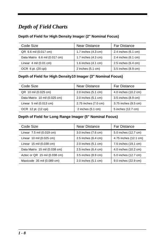
Depth of Field Charts
Depth of Field for High Density Imager (2" Nominal Focus)
Depth of Field for High Density10 Imager (3" Nominal Focus)
Depth of Field for Long Range Imager (5" Nominal Focus)
Code Size Near Distance Far Distance
QR 6.6 mil (0.017 cm) 1.7 inches (4.3 cm) 2.4 inches (6.1 cm)
Data Matrix 6.6 mil (0.017 cm) 1.7 inches (4.3 cm) 2.4 inches (6.1 cm)
Linear 4 mil (0.01 cm) 1.6 inches (4.1 cm) 2.5 inches (6.4 cm)
OCR 6 pt. (20 cpi) 2 inches (5.1 cm) 3.5 inches (8.9 cm)
Code Size Near Distance Far Distance
QR 10 mil (0.025 cm) 2.0 inches (5.1 cm) 4.0 inches (10.2 cm)
Data Matrix 10 mil (0.025 cm) 2.0 inches (5.1 cm) 3.5 inches (8.9 cm)
Linear 5 mil (0.013 cm) 2.75 inches (7.0 cm) 3.75 inches (9.5 cm)
OCR 12 pt. (12 cpi) 2 inches (5.1 cm) 5 inches (12.7 cm)
Code Size Near Distance Far Distance
Linear 7.5 mil (0.019 cm) 3.0 inches (7.6 cm) 5.0 inches (12.7 cm)
Linear 10 mil (0.025 cm) 2.5 inches (6.4 cm) 4.75 inches (12.1 cm)
Linear 15 mil (0.038 cm) 2.0 inches (5.1 cm) 7.5 inches (19.1 cm)
Data Matrix 15 mil (0.038 cm) 2.5 inches (6.4 cm) 4.0 inches (10.2 cm)
Aztec or QR 15 mil (0.038 cm) 3.5 inches (8.9 cm) 5.0 inches (12.7 cm)
Maxicode 35 mil (0.089 cm) 2.0 inches (5.1 cm) 9.0 inches (22.9 cm)
1 - 8

2
ProgrammingIntroduction
Use this section to program the hand-held Imager.
This programming section contains the following menuing selections:
• General Selections
• Terminal Interface Selections
• Keyboard Selections
• Communication Settings
• Imager Selections
• Output Selections
• Prefix/Suffix Selections
• Data Formatter Selections
• Output Sequence Selections
2 - 1

Reset Factory Settings
All operating parameters are stored in nonvolatile memory resident in the Imager, where they are permanently retained in the event of a power interruption. When you receive your Imager, certain operating parameters have already been set. These are the factory defaults, indicated by the symbol “✱ ” on the programming menu pages (beneath the default programming symbol). Default charts begin on page 5-1.
Depending on your model, scan one of the following bar codes to set the imager to the original factory settings, clearing any programming changes you may have made.
Status Check
Read the Show Software Revision symbol to transmit the software revision level to the host terminal. The software revision will be printed out as “REV_SW:$ProjectRevision:1.xx$;REV_WA:31204734-xxx.”
Read the Show Data Formats symbol to transmit the existing Data Format Editor formats. One format per line will be printed out.
LR
HD10HD
Show Software Revision
Show Data Formats
2 - 2

All Symbologies
If you want to decode all the symbologies allowable for your scanner, scan the All Symbologies On code.
Revision Selections
Both the following programming codes would not normally be needed unless you have a problem with the unit. An Application Support Representative may request the boot code or power PC revision information in order to trouble shoot a problem.
All SymbologiesOn
All SymbologiesOff
Boot Code RevisionPower PC Revision
2 - 3
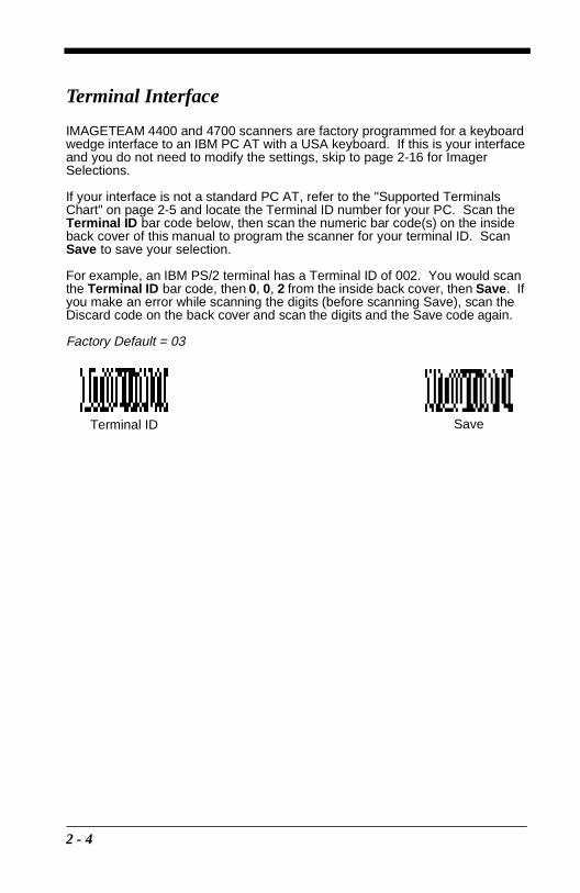
Terminal Interface
IMAGETEAM 4400 and 4700 scanners are factory programmed for a keyboard wedge interface to an IBM PC AT with a USA keyboard. If this is your interface and you do not need to modify the settings, skip to page 2-16 for Imager Selections.
If your interface is not a standard PC AT, refer to the "Supported Terminals Chart" on page 2-5 and locate the Terminal ID number for your PC. Scan the Terminal ID bar code below, then scan the numeric bar code(s) on the inside back cover of this manual to program the scanner for your terminal ID. Scan Save to save your selection.
For example, an IBM PS/2 terminal has a Terminal ID of 002. You would scan the Terminal ID bar code, then 0, 0, 2 from the inside back cover, then Save. If you make an error while scanning the digits (before scanning Save), scan the Discard code on the back cover and scan the digits and the Save code again.
Factory Default = 03
Terminal ID Save
2 - 4

Supported Terminals Chart
Note: These interfaces are available only for units that have 1 megabyte of program memory. The software revision indicates the memory size. If you are not certain of your unit’s memory, please contact Welch Allyn’s Application Support (see page 10-5).
Terminal Model(s) Terminal I.D.
DEC PC433 SE (Portable PC) 003
DELL Latitude (Portable PC) 003
DTK 486 SLC (Portable PC) 003
Fujitsu Stylistic (Portable PC) 003
HHLC (Code 128 Emulation) 089*
* This capability is not available for the IT4700. Contact the factory if this capability isneeded for the IT4700.
IBM PC X 001
IBM PS/2 25, 30, 77DX2 002
IBM AT, PS/2 30-286, 50, 55SX, 60, 70, 003, 70-061, 70-121, 80
IBM AT Compatibles Keyboard Emulation(Non-wedge) 003
IBM Thinkpad 360 CSE, 34, 750 (Portable PC) 097
IBM Thinkpad 365, 755 CV (Portable PC) 003
IBM AT Thinkpad 106
Midwest Micro Elite TS 30 PS (Portable PC) 003
Mitak 4022 (Portable PC) 003
Olivetti M19, M24, M28, M200 001
Olivetti M240, M250, M290, M380, P500 003
Reliasys TR 175 003
RS-232 TTL 000
Televideo 990, 995, 9060 002
Texas Instruments Extensa 560CD (Portable PC) 003
Toshiba 2600 (Portable PC) 003
Toshiba Satellite T1960, T2130, CS (Portable PC) 003
Zenith Z-note (Portable PC) 003
2 - 5

Keyboard Country
Scan the Program Keyboard Country bar code below, then scan the numeric bar code(s) from the inside back cover, then the Save bar code to program the keyboard for your country. As a general rule, the following characters are not supported by the scanner for countries other than the United States:
@ | $ # { } [ ] = / ‘ \ < > ~
Country Code Scan Country Code ScanBelgium..................... 1 Italy ........................5Denmark ................... 8 Norway...................9Finland...................... 2 Spain......................10France ...................... 3 Switzerland ............6Germany/Austria....... 4 USA (Default).........0Great Britain ............. 7
Keyboard Country
Save
2 - 6

Keyboard Style
This programs keyboard styles, such as Caps Lock and Shift Lock. Default = Regular.
Regular is used when you normally have the Caps Lock key off.
Caps Lock is used when you normally have the Caps Lock key on.
Shift Lock is used when you normally have the Shift Lock key on. (Not common to U.S. keyboards.)
Automatic Caps Lock is used if you change the Caps Lock key on and off. The software tracks and reflects if you have Caps Lock on or off (AT and PS/2 only). This selection can only be used with systems that have an LED which notes the Caps Lock status.
Emulate External Keyboard should be scanned if you do not have an external keyboard (IBM AT or equivalent), but should not be used for laptops. To connect the scanner to a laptop, use "Automatic Direct Connect Mode On"on page 2-8.
* Regular Caps Lock
Shift Lock
Emulate External Keyboard
Automatic Caps Lock
2 - 7

Keyboard Modifiers
This modifies special keyboard features, such as CTRL+ ASCII codes and Turbo Mode.
Control + ASCII Mode On - The scanner sends key combinations for ASCII control characters for values 00-1F. Refer to "Keyboard Function Relationships" on page 2-9 for CTRL+ ASCII Values. Default = Off
Turbo Mode - The scanner sends characters to an IBM AT terminal faster. (For use with IBM AT only.) If the terminal drops characters, do not use Turbo Mode. Default = Off
Numeric Keypad Mode - Sends numeric characters as if entered from a numeric keypad. Default = Off
Automatic Direct Connect - Use this selection if you are using a laptop whose keyboard is disabled when you plug in the scanner. This selection can also be used if you have an IBM AT style terminal and the system is dropping characters. Default = Off
Control + ASCII Mode On
* Control + ASCII Mode Off
Turbo Mode On * Turbo Mode Off
Numeric Keypad Mode On
* Numeric Keypad Mode Off
Automatic Direct Connect Mode On
* Automatic Direct Connect Mode Off
2 - 8

Keyboard Function Relationships
The following Keyboard Function Code, Hex/ASCII Value, and Full ASCII “CTRL”+ relationships apply to all terminals that can be used with the scanner.
Function Code HEX/ASCII Value Full ASCII “CTRL” +NUL 00 2SOH 01 ASTX 02 BETX 03 CEOT 04 DENQ 05 EACK 06 FBEL 07 GBS 08 HHT 09 ILF 0A JVT 0B KFF 0C LCR 0D MSO 0E NSI 0F ODLE 10 PDC1 11 QDC2 12 RDC3 13 SDC4 14 TNAK 15 USYN 16 VETB 17 WCAN 18 XEM 19 YSUB 1A ZESC 1B [FS 1C \GS 1D ]RS 1E 6US 1F -
2 - 9

Connecting the Scanner to a Serial Port
6. Turn off power to the terminal/computer.
7. Connect the interface cable to the scanner.
8. Connect the interface cable to the 5 or 14 VDC power supply and plug in the power supply. The scanner will beep twice.
9. Connect the interface cable to the terminal/computer.
10. Turn the terminal/computer power back on.
11. Verify the scanner operation by scanning a bar code from the back cover of this manual. The scanner will beep once.
The scanner is now connected and ready to communicate with your terminal/PC. Turn to "Communication Settings" on page 2-11 to program the communication parameters for a serial interface.
2
3
1
Power Supply
Interface Cable
2 - 10

Communication Settings
<Default All RS-232 Communication Settings>
Parity
Parity provides a means of checking character bit patterns for validity. The Imager can be configured to operate under Mark, Space, Odd, Even, or No (None) parity options. The host terminal must be set up for the same parity as the Imager, to ensure reliable communication.
SpaceMark
* None
Odd Even
2 - 11
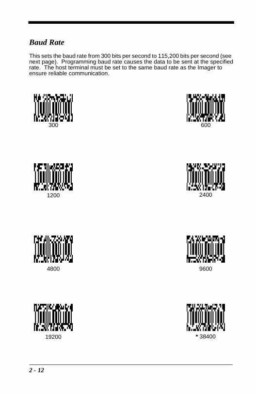
Baud Rate
This sets the baud rate from 300 bits per second to 115,200 bits per second (see next page). Programming baud rate causes the data to be sent at the specified rate. The host terminal must be set to the same baud rate as the Imager to ensure reliable communication.
300 600
1200 2400
96004800
19200 * 38400
2 - 12

Baud Rate, continued
Word Length Data Bits
You can set the Word Length at 7 or 8 bits of data per character. If an application requires only ASCII Hex characters 0 through 7F decimal (text, digits, and punctuation), select 7 data bits. For applications requiring use of the full ASCII set, select 8 data bits per character.
Word Length Stop Bits
Word Length can be set to one or two stop bits.
57600 115200
7 Data Bits * 8 Data Bits
* 1 Stop Bit 2 Stop Bits
2 - 13

Hardware Flow Control
When hardware flow control is on, the software checks for a CTS signal before sending data. This option is useful when your application supports the CTS signal.
Software Flow Control
This allows control of data transmission from the Imager using software commands from the host device. When this feature is turned off, no data flow control is used. When Data Flow Control is turned on, the host device suspends transmission by sending the XOFF character (DC3, hex 13) to the Imager. To resume transmission, the host sends the XON character (DC1, hex 11). Data transmission continues where it left off when XOFF was sent.
On * Off
* OffOn
2 - 14

Serial Triggering
This provides a means of sending a serial trigger command to start and stop decoding. When this feature is turned off, the Imager will not respond to serial trigger commands. When serial triggering is turned on, the Imager requires a serial trigger character to activate scanning and decoding. The unit continues to scan and decode bar codes until the Trigger Off character turns off the scanner, or a time out occurs.
On the "Decimal to Hex to ASCII Conversion Chart" on page 2-34, find the hex characters you want to use to turn the trigger on and off. Locate the decimal values for those characters and scan the 2 digits for each one from the Programming Chart in the back of this manual.
When Serial Triggering is On, the default Trigger On decimal character is 18 (hex 12, DC2), and the default Trigger Off decimal character is 20 (hex 14, DC4).
‡ A one to three digit decimal number and Save are required after reading this programming symbol. See "Decimal to Hex to ASCII Conversion Chart" on page 2-34, and the Programming Chart (inside back cover).
* OffOn
* Trigger Defaults
Trigger On ‡ Trigger Off ‡
2 - 15
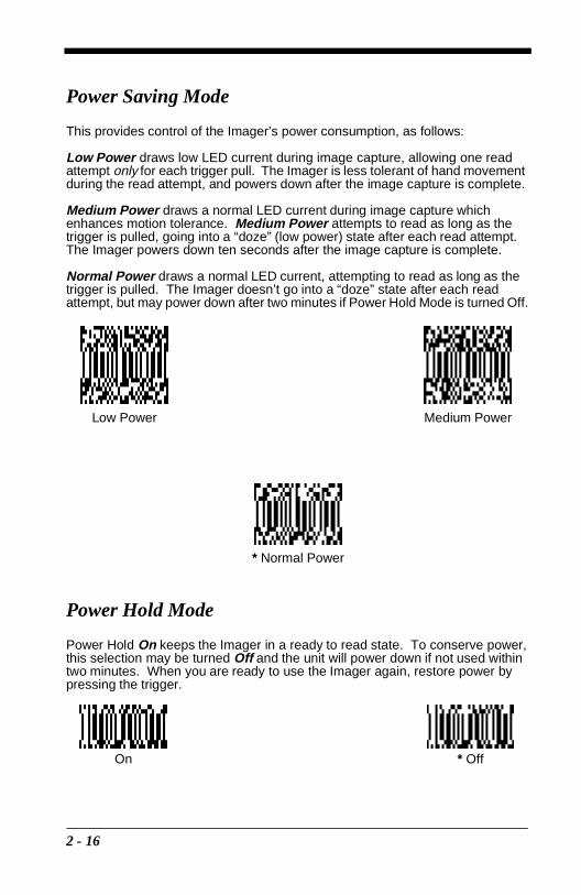
Power Saving Mode
This provides control of the Imager’s power consumption, as follows:
Low Power draws low LED current during image capture, allowing one read attempt only for each trigger pull. The Imager is less tolerant of hand movement during the read attempt, and powers down after the image capture is complete.
Medium Power draws a normal LED current during image capture which enhances motion tolerance. Medium Power attempts to read as long as the trigger is pulled, going into a “doze” (low power) state after each read attempt. The Imager powers down ten seconds after the image capture is complete.
Normal Power draws a normal LED current, attempting to read as long as the trigger is pulled. The Imager doesn’t go into a “doze” state after each read attempt, but may power down after two minutes if Power Hold Mode is turned Off.
Power Hold Mode
Power Hold On keeps the Imager in a ready to read state. To conserve power, this selection may be turned Off and the unit will power down if not used within two minutes. When you are ready to use the Imager again, restore power by pressing the trigger.
Low Power Medium Power
* Normal Power
On * Off
2 - 16

LED Power Level
This selection allows you to adjust LED brightness.
Off is used when no illumination is needed. Low is used if low illumination is sufficient. High (the default) is the brightest setting.
LED Flashing
If LED Flashing is turned off, the average current draw is increased and the aiming light won’t illuminate while the scanner reads a bar code.
† If LED Flashing is turned off, the average current draw is increased and the view finder won’t illuminate during the reading phase.
Off Low
* High
Off † * On
2 - 17

Aimer Delay
The aimer delay allows a delay time for the operator to aim the scanner before the picture is taken. Use these codes to set the time between when the trigger is pulled and when the picture is taken. During the delay time, the aiming light will appear, but the LEDs won’t turn on until the delay time is over.
Aimer Timeout
Use this selection to set a timeout (in seconds) of the Imager’s aiming light when the device is not reading a bar code. Default setting = 60 seconds
‡ A one- to three digit number and Save are required after reading this programming symbol. Refer to the Programming Chart (inside back cover).
400 milliseconds
* Off (no delay)
200 milliseconds
Set Timeout ‡
2 - 18

Aimer Interval
Aimer Interval turns off the aiming light, or programs the aimer to come on at certain intervals when reading symbols with the scanner. You may program the scanner to use the aimer Every Read, Every Second Read, or Every Third Read. You may also program the scanner to use the aimer every “x” reads, by entering a number from 0 to 999 to indicate “x.”
‡ A one- to three digit number and Save are required after reading this programming symbol. Refer to the Programming Chart (inside back cover).
* Every ReadOff
Every “x” Reads ‡
Every Second Read Every Third Read
2 - 19

AutoTrigger
Two AutoTrigger Modes are available: Scan Stand and Presentation Mode.
When a unit is in Scan Stand mode, the LED shines at the symbol on the base of the stand which tells it to remain idle. When a different code is presented, the Imager is triggered to read the new code.
Presentation mode is for those applications where a scan stand will not work, i.e., when large packages must be scanned. To program the device for presentation mode, refer to "Presentation Mode" on page 2-21.
Scan Stand
This selection programs the Imager to work in a Scan Stand.
Scan Stand LED Intensity
This sets the idle LED intensity when the Imager is in Scan Stand mode. When a unit is in Scan Stand mode, the LED shines at the symbol on the base of the stand which tells it to remain idle. When a different code is presented, the Imager is triggered to read the new code. If the Imager has difficulty going back to reading the Scan Stand’s fixed code, for instance, in a low lighting situation, you may want to adjust the Scan Stand LED Intensity. A two digit number between 15 and 75 must be input after the Scan Stand LED Intensity programming code is scanned. A 15 corresponds to the lowest intensity level, and a 75 corresponds to the highest intensity level. 15 is the default setting.
Note that when the unit is triggered to read a code, the unit uses the LED power level specified through "LED Power Level" on page 2-17.
On* Off
Set Scan Stand LED Intensity
2 - 20
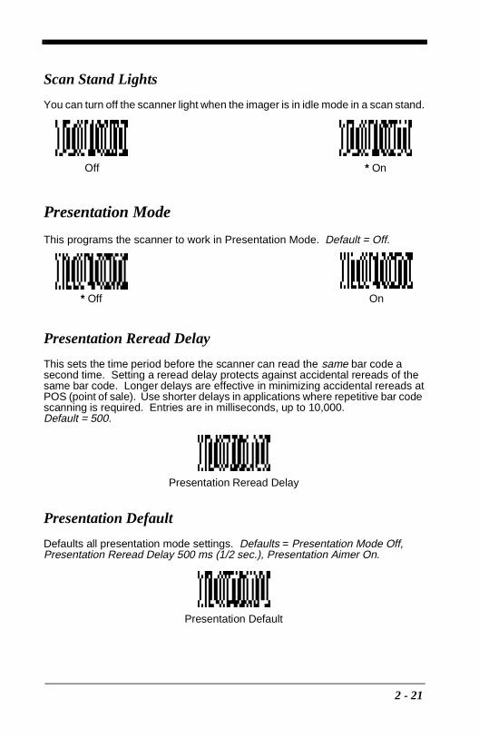
Scan Stand Lights
You can turn off the scanner light when the imager is in idle mode in a scan stand.
Presentation Mode
This programs the scanner to work in Presentation Mode. Default = Off.
Presentation Reread Delay
This sets the time period before the scanner can read the same bar code a second time. Setting a reread delay protects against accidental rereads of the same bar code. Longer delays are effective in minimizing accidental rereads at POS (point of sale). Use shorter delays in applications where repetitive bar code scanning is required. Entries are in milliseconds, up to 10,000. Default = 500.
Presentation Default
Defaults all presentation mode settings. Defaults = Presentation Mode Off, Presentation Reread Delay 500 ms (1/2 sec.), Presentation Aimer On.
* OnOff
On* Off
Presentation Reread Delay
Presentation Default
2 - 21
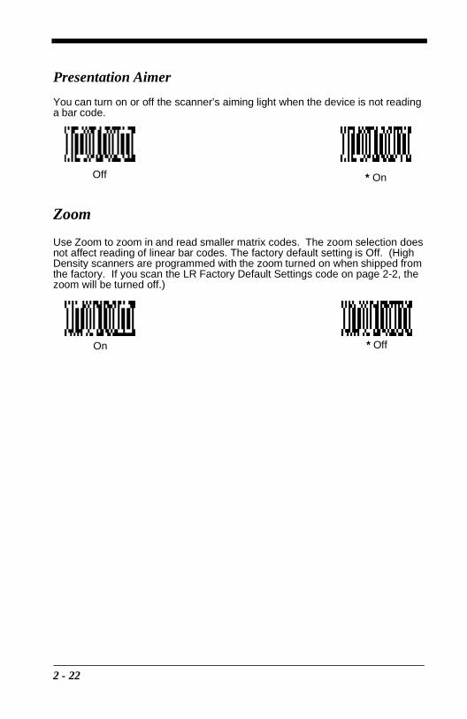
Presentation Aimer
You can turn on or off the scanner’s aiming light when the device is not reading a bar code.
Zoom
Use Zoom to zoom in and read smaller matrix codes. The zoom selection does not affect reading of linear bar codes. The factory default setting is Off. (High Density scanners are programmed with the zoom turned on when shipped from the factory. If you scan the LR Factory Default Settings code on page 2-2, the zoom will be turned off.)
Off * On
* OffOn
2 - 22
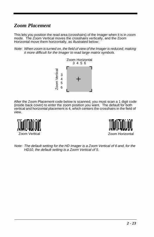
Zoom Placement
This lets you position the read area (crosshairs) of the Imager when it is in zoom mode. The Zoom Vertical moves the crosshairs vertically, and the Zoom Horizontal move them horizontally, as illustrated below:
Note: When zoom is turned on, the field of view of the Imager is reduced, making it more difficult for the Imager to read large matrix symbols.
After the Zoom Placement code below is scanned, you must scan a 1 digit code (inside back cover) to enter the zoom position you want. The default for both vertical and horizontal placement is 4, which centers the crosshairs in the field of view.
Note: The default setting for the HD Imager is a Zoom Vertical of 6 and, for the HD10, the default setting is a Zoom Vertical of 5.
Zoom HorizontalZ
oom
Ver
tical
3 4 5 6
3456
Zoom Vertical Zoom Horizontal
2 - 23
Beeper Volume
Power Up Beeper
Output Sequence Beeper
If you are using an Output Sequence (see "Output Sequence Overview" on page 2-41), you may want to hear a beep after each bar code as it is read. Scan Output Sequence Beeper On to enable this feature, or Off to disable it.
Off
* HighMedium
Low
* On Off
* On Off
2 - 24

Beep On Decode
If you want the scanner to beep each time it reads a bar code, leave this setting On. If you don’t want it to beep on each read, but do want it to beep for other events, set this selection to Off.
Beeper Default
Defaults all beeper settings. Defaults = Beeper Volume High, Power Up Beeper On, Output Sequence Beeper On, Beep On Read On.
* On Off
Beeper Default
2 - 25

Intercharacter, Interfunction, and Intermessage DelaysSome terminals drop information (characters) if data comes through too quickly. Intercharacter, interfunction, and intermessage delays slow the transmission of data, which increases data integrity.
Each delay is composed of a 5 millisecond step. You can program up to 99 steps (of 5 ms each).
Intercharacter Delay
This is a delay of up to 495 milliseconds (in multiples of 5) placed between the transmission of each character of scanned data. You can program up to 99 steps (of 5 ms each). Scan the Intercharacter Delay bar code below, then scan the number of steps, and the SAVE bar code from the inside back cover.
Note: If you make an error while scanning the digits (before scanning Save), scan Discard on the back cover and scan the correct digits and Save again.
To remove this delay, scan the Intercharacter Delay bar code, then set the number of steps to 00. Scan the SAVE bar code from the inside back cover.
1 2 3 4 5
Intercharacter Delay
Prefix Scanned Data Suffix
Intercharacter Delay
2 - 26

Interfunction Delay
This is a delay of up to 495 milliseconds (in multiples of 5) placed between the transmission of each segment of the message string. You can program up to 99 steps (of 5 ms each). Scan the Interfunction Delay bar code below, then scan the number of steps, and the SAVE bar code from the inside back cover.
Note: If you make an error while scanning the digits (before scanning Save), scan Discard on the back cover and scan the correct digits and Save again.
To remove this delay, scan the Interfunction Delay bar code, then set the number of steps to 00. Scan the SAVE bar code from the inside back cover.
Interfunction Delays
Prefix Scanned Data Suffix
1 2 3 4 5STX HT CR LF
Interfunction Delay
2 - 27
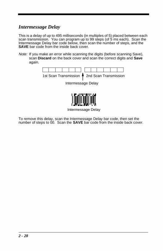
Intermessage Delay
This is a delay of up to 495 milliseconds (in multiples of 5) placed between each scan transmission. You can program up to 99 steps (of 5 ms each). Scan the Intermessage Delay bar code below, then scan the number of steps, and the SAVE bar code from the inside back cover.
Note: If you make an error while scanning the digits (before scanning Save), scan Discard on the back cover and scan the correct digits and Save again.
To remove this delay, scan the Intermessage Delay bar code, then set the number of steps to 00. Scan the SAVE bar code from the inside back cover.
2nd Scan Transmission1st Scan Transmission
Intermessage Delay
Intermessage Delay
2 - 28
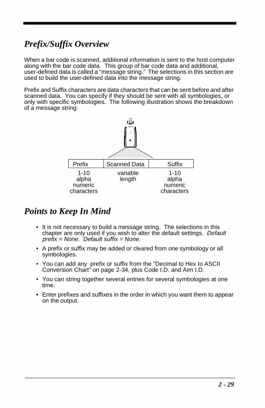
Prefix/Suffix Overview
When a bar code is scanned, additional information is sent to the host computer along with the bar code data. This group of bar code data and additional, user-defined data is called a “message string.” The selections in this section are used to build the user-defined data into the message string.
Prefix and Suffix characters are data characters that can be sent before and after scanned data. You can specify if they should be sent with all symbologies, or only with specific symbologies. The following illustration shows the breakdown of a message string:
Points to Keep In Mind
• It is not necessary to build a message string. The selections in this chapter are only used if you wish to alter the default settings. Default prefix = None. Default suffix = None.
• A prefix or suffix may be added or cleared from one symbology or all symbologies.
• You can add any prefix or suffix from the "Decimal to Hex to ASCII Conversion Chart" on page 2-34, plus Code I.D. and Aim I.D.
• You can string together several entries for several symbologies at one time.
• Enter prefixes and suffixes in the order in which you want them to appear on the output.
Prefix Scanned Data Suffix
1-10alpha
numeric characters
variable length
1-10alpha
numeric characters
2 - 29

Adding a Prefix or Suffix
1. Scan the Add Prefix (page 2-32) or Add Suffix symbol (page 2-32).
2. Determine the 2 digit Hex value from the "Symbology Chart "on page 2-33 for the symbology to which you want to apply the prefix or suffix.
3. Scan the 2 hex digits from the Programming Chart inside the back cover or scan 9, 9 for all symbologies.
4. Determine the hex value from the "Symbology Chart "on page 2-33 for the prefix or suffix you wish to enter.
5. Scan the 2 digit hex value from the Programming Chart inside the back cover.
Note: Repeat Steps 4 and 5 for every prefix or suffix character.
Note: To add the Code I.D., scan 5, C, 8, 0.To add AIM I.D., scan 5, C, 8, 1.To add a backslash (\), scan 5, C, 5, C.
6. Scan Save to exit and save, or scan Discard to exit without saving.
Repeat Steps 1-6 to add a prefix or suffix for another symbology.
Example: Add a Suffix to a specific symbology
To send a CR (carriage return)Suffix for UPC only:
1. Scan Add Suffix.
2. Determine the 2 digit hex value from the "Symbology Chart" on page 2-33 for UPC.
3. Scan 6, 3 from the Programming Chart (inside back cover).
4. Determine the hex value from the "Decimal to Hex to ASCII Conversion Chart" on page 2-34 for the CR (carriage return).
5. Scan 0, D from the Programming Chart (inside back cover).
6. Scan Save, or scan Discard to exit without saving.
Clearing One or All Prefixes or Suffixes
You can clear a single prefix or suffix, or clear all prefixes/suffixes for a symbology. When you Clear One Prefix (Suffix), the specific character you select is deleted from the symbology you want. When you Clear All Prefixes (Suffixes), all the prefixes or suffixes for a symbology are deleted.
1. Scan the Clear One Prefix or symbol.
2. Determine the 2 digit Hex value from the "Symbology Chart "on page 2-33 for the symbology from which you want to clear the prefix or suffix.
3. Scan the 2 digit hex value from the Programming Chart inside the back cover or scan 9, 9 for all symbologies.
Your change is automatically saved.
2 - 30

Add a Carriage Return Suffix to All Symbologies
Scan the following bar code if you wish to add a Carriage Return Suffix to all symbologies at once. This action first clears all current suffixes, then programs a carriage return suffix for all symbologies.
Add a Code I.D. Prefix to All Symbologies
This selection allows you to turn on (or off) transmission of a Code I.D. before the decoded symbology. (See the "Symbology Chart"on page 2-33 for the single character code that identifies each symbology.) This action first clears all current prefixes, then programs a Code I.D. prefix for all symbologies.
Add an AIM I.D. Prefix to All Symbologies
This selection allows you to turn on (or off) transmission of an AIM I.D. before the decoded symbology. (See the "Symbology Chart"on page 2-33 for the single character code that identifies each symbology.) This action first clears all current prefixes, then programs an AIM I.D. prefix for all symbologies.
(See AIM Guidelines on Symbology Identifiers for more information on the AIM symbology ID characters.)
Add CR SuffixAll Symbologies
Add Code ID PrefixAll Symbologies
Add AIM ID PrefixAll Symbologies
2 - 31

Prefix Entries
Suffix Entries
† One or more two digit numbers and Save are required after reading this programming symbol. Refer to the Programming Chart (inside back cover).
Exit Selections
Add Prefix †
Clear All Prefixes
Clear One Prefix †
Add Suffix †
Clear All Suffixes
Clear One Suffix †
Save Discard
2 - 32

Symbology Chart
Note: Prefix/Suffix entries for specific symbologies override the universal (All Symbologies, 99) entry.
† All Symbologies: Prefix/Suffix programming only!
** Not available in standard product. Only available when ordered in custom firmware
SymbologyCode
IDAIMID
HexID
SymbologyCode
IDAIMID
HexID
Australian 4 State A [X 41 Interleaved 2 of 5 e [l 65
Aztec Code z [z 7A Japanese Postal J [X 4A
BC412** g [X 67 Kix (Dutch) Postal K [X 4B
BPO 4 State B [X 42 Maxicode x [U 78
Canadian 4 State C [X 43 Micro PDF417 R [L 52
Codabar a [F 61 No Read 9C
Codablock-F q [O 71 OCR o [Y 6F
Code 39 b [A 62 PDF417 r [L 72
Code 49 l [T 6C Planet Code L [X 4C
Code 93/93i i [G 69 Postnet P [X 50
Code 128 j [C 6A QR Code s [Q 73
Code Z** u [X 75 RSS/Composites y [e 79
Data Matrix w [d 77 UPC c [E 63
EAN d [E 64 Vericode** v [V 76
Iata 2 of 5 f [R 66 All Symbologies † 99
2 - 33

Decimal to Hex to ASCII Conversion Chart
Dec. Hex ASCII Dec. Hex ASCII Dec. Hex ASCII Dec. Hex ASCII
0 00 NUL 32 20 SP 64 40 @ 96 60 ‘1 01 SOH 33 21 ! 65 41 A 97 61 a2 02 STX 34 22 “ 66 42 b 98 62 b3 03 ETX 35 23 # 67 43 C 99 63 c4 04 EOT 36 24 $ 68 44 D 100 64 d5 05 ENQ 37 25 % 69 45 E 101 65 e6 06 ACK 38 26 & 70 46 F 102 66 f7 07 BEL 39 27 ‘ 71 47 G 103 67 g8 08 BS 40 28 ( 72 48 H 104 68 h9 09 HT 41 29 ) 73 49 l 105 69 i10 0A LF 42 2A * 74 4A J 106 6A j11 0B VT 43 2B + 75 4B K 107 6B k12 0C FF 44 2C , 76 4C L 108 6C l13 0D CR 45 2D - 77 4D M 109 6D m14 0E SO 46 2E . 78 4E N 110 6E n15 0F SI 47 2F / 79 4F O 111 6F o16 10 DLE 48 30 0 80 50 P 112 70 p17 11 DC1 49 31 1 81 51 Q 113 71 q18 12 DC2 50 32 2 82 52 R 114 72 r19 13 DC3 51 33 3 83 53 S 115 73 s20 14 DC4 52 34 4 84 54 T 116 74 t21 15 NAK 53 35 5 85 55 U 117 75 u22 16 SYN 54 36 6 86 56 V 118 76 v23 17 ETB 55 37 7 87 57 W 119 77 w24 18 CAN 56 38 8 88 58 X 120 78 x25 19 EM 57 39 9 89 59 Y 121 79 y26 1A SUB 58 3A : 90 5A Z 122 7A z27 1B ESC 59 3B ; 91 5B [ 123 7B {28 1C FS 60 3C < 92 5C \ 124 7C |29 1D GS 61 3D = 93 5D ] 125 7D }30 1E RS 62 3E > 94 5E ^ 126 7E ~31 1F US 63 3F ? 95 5F _ 127 7F DEL
2 - 34

Data Format Editor Overview
The Data Format Editor selections are used to edit scanned data. For example, you can use the Data Format Editor to insert characters at certain points in bar code data as it is scanned.
It is not necessary to use the Data Format Editor. A set of defaults for the data format is already programmed in the scanner. The selections in the following pages are used only if you wish to alter the default settings. Default Data Format setting = none.
If you have changed data format settings, and wish to clear all formats and return to the defaults, scan the Default Data Format code.
To Add a Data Format
1. Scan the Enter Data Format symbol (page 2-38).2. Primary/Alternate Format
Determine if this will be your primary data format, or one of 3 alternate for-mats. (Alternate formats allow you “single shot” capability to scan one bar code using a different data format. After the one bar code has been read, the scanner reverts to the primary data format. See "Alternate Data Formats" on page 2-40.) If you are programming the primary format, scan 0. If you are programming an alternate format, scan 1, 2, or 3, depending on the alternate format you are programming.
3. Terminal TypeRefer to the "Supported Terminals Chart"on page 2-5 and locate the Termi-nal ID number for your PC. Scan three numeric bar codes on the inside back cover to program the scanner for your terminal ID (you must enter 3 digits). For example, scan 0 0 3 for an AT wedge.
4. Code I.D.On page 2-33, find the symbology to which you want to apply the data for-mat. Locate the Hex value for that symbology and scan the 2 digit hex value from the Programming Chart.
5. LengthSpecify what length (up to 9999 characters) of data will be acceptable for this symbology. Scan the four digit data length from the Programming Chart. (Note: 50 characters is entered as 0050. 9999 is a universal number, indi-cating all lengths.)
6. Editor CommandsRefer to the "Format Editor Commands" on page 2-36. Scan the symbols that represent the command you want to enter. 94 alphanumeric characters may be entered for each symbology data format.
7. Scan Save to save your entries.
2 - 35

Other Programming Selections
• Clear One Data Format This deletes one data format for one symbology. If you are clearing the primary format, scan 0. If you are clearing an alternate format, scan 1, 2, or 3, depending on the alternate format you are clearing. Scan the Terminal Type (refer to the "Supported Terminals Chart"on page 2-5), Code I.D. and the length of the format you want to delete. That length data format for that symbology is deleted and all other formats are unaffected.
• SaveThis exits, saving any Data Format changes.
• DiscardThis exits without saving any Data Format changes.
Format Editor Commands
Send Commands
F1 Send all characters followed by “xx” key or function code, starting from current cursor position. Syntax = F1xx (xx stands for the hex value for an ASCII code, see "Decimal to Hex to ASCII Conversion Chart" on page 2-34.)
F2 Send “nn” characters followed by “xx” key or function code, starting from current cursor position. Syntax = F2nnxx (nn stands for the numeric value (00-99) for the number of characters and xx stands for the hex value for an ASCII code. See "Decimal to Hex to ASCII Conversion Chart" on page 2-34.)
F3 Send up to but not including “ss” character (Search and Send) starting from current cursor position, leaving cursor pointing to “ss” character followed by “xx” key or function code. Syntax = F3ssxx (ss and xx both stand for the hex values for ASCII codes, see "Decimal to Hex to ASCII Conversion Chart" on page 2-34.)
F4 Send “xx” character “nn” times (Insert) leaving cursor in current cursor position. Syntax = F4xxnn (xx stands for the hex value for an ASCII code, see "Decimal to Hex to ASCII Conversion Chart" on page 2-34, and nn is the numeric value (00-99) for the number of times it should be sent.)
E9 Send all but the last “nn” characters, starting from the current cursor position. Syntax = E9nn (nn is the numeric value (00-99) for the number of characters that will not be sent at the end of the message.)
Move Commands
F5 Move the cursor ahead “nn” characters from current cursor position. Syntax = F5nn (nn stands for the numeric value (00-99) for the number of characters the cursor should be moved ahead.)
F6 Move the cursor back “nn” characters from current cursor position. Syntax = F6nn (nn stands for the numeric value (00-99) for the number of characters the cursor should be moved back.)
F7 Move the cursor to the beginning of the data string. Syntax = F7.EA Move the cursor to the end of the data string. Syntax = EA
2 - 36

Search Commands
F8 Search ahead for “xx” character from current cursor position, leaving cursor pointing to “xx” character. Syntax = F8xx (xx stands for the hex value for an ASCII code, see "Decimal to Hex to ASCII Conversion Chart" on page 2-34.)
F9 Search back for “xx” character from current cursor position, leaving cursor pointing to “xx” character. Syntax = F9xx (xx stands for the hex value for an ASCII code, see "Decimal to Hex to ASCII Conversion Chart" on page 2-34.)
E6 Search ahead for the last instance of “xx” character from the current cursor position, then increment cursor. Syntax = E6xx (xx stands for the hex value for an ASCII code, see "Decimal to Hex to ASCII Conversion Chart" on page 2-34.)
E7 Search back for the last instance of “xx” character from the current cursor position, then increment cursor. Syntax = E7xx (xx stands for the hex value for an ASCII code, see "Decimal to Hex to ASCII Conversion Chart" on page 2-34.)
Miscellaneous Commands
FB Suppress all occurrences of up to 15 different characters, starting at the current cursor position, as the cursor is advanced by other commands. When the FC command is encountered, the suppress function is terminated. The cursor is not moved by the FB command. Syntax = FBnnxxyy . .zz where nn is a count of the number suppress characters in the list and xxyy .. zz is the list of characters to be suppressed. (xx stands for the hex value for an ASCII code, see "Decimal to Hex to ASCII Conversion Chart" on page 2-34.)
FC Disable suppress filter and clear all suppressed characters. Syntax = FC.E4 Replaces up to 15 characters in the data string with user specified
characters. Replacement continues until the E5 command is encountered. Syntax = E4nnxx1xx2yy1yy2...zz1zz2 where nn is the total count of both characters to be replaced plus replacement characters; xx1 defines characters to be replaced and xx2 defines replacement characters, continuing through zz1 and zz2.
E5 Terminates character replacement. Syntax = E5.FE Compare character in current cursor position to the character “xx.” If
characters are equal, increment cursor. If characters are not equal, no format match. Syntax = FExx (xx stands for the hex value for an ASCII code, see "Decimal to Hex to ASCII Conversion Chart" on page 2-34.)
EC Check to make sure there is a numeric character at the current cursor position. If character is not numeric, format is aborted. Syntax = EC.
ED Check to make sure there is a non-numeric character at the current cursor position. If character is numeric, format is aborted. Syntax = ED.
2 - 37

Data Format Editor
See page 2-35 through page 2-37 for a description of Data Format selections and commands.
Exit Selections
† One or more two digit numbers and Save are required after reading this programming symbol. Refer to the Programming Chart (inside back cover).
Enter Data Format † Default Data Format
(none)
Clear OneData Format †
Clear All Data Formats
Save Current Data Format Changes
Discard Current Data Format Changes
2 - 38

Data Formatter
When Data Formatter is turned off, the bar code data is output to the host as read (including prefixes and suffixes).
Require Data Format
When Data Formatter is required, all input data must conform to an edited format or the scanner does not transmit the input data to the host device.
Show Data Formats
Read the Show Data Formats bar code to transmit the existing data formats. One format per line is printed out.
* On Off
Required
Show Data Formats
2 - 39

Alternate Data Formats
Alternate formats allow you “single shot” capability to scan one bar code using a different data format than your primary format. When data formats are programmed (see page 2-35), you must input whether you are programming the primary format, or an alternate format numbered 1, 2, or 3.
An alternate format is initiated by scanning one of the 3 alternate format bar codes below. The scanner will scan the next bar code, formatting the data with the selected alternate format, then revert immediately to the primary format.
Alternate Data Format 1
Alternate Data Format 2
Alternate Data Format 3
2 - 40

Output Sequence Overview
Require Output Sequence
When turned off, the bar code data will be output to the host as the Imager decodes it. When turned on, all output data must conform to an edited sequence or the Imager will not transmit the output data to the host device.
Note: This selection is unavailable when the Multiple Symbols Selection is turned on.
Output Sequence Editor
This programming selection allows you to program the Imager to output data (when scanning more than one symbol) in whatever order your application requires. Reading the Default Sequence symbol programs the Imager to the Universal values, shown below. These are the defaults. Be certain you want to delete or clear all formats before you read the Default Sequence symbol.
Note: To make Output Sequence Editor selections, you’ll need to know the code I.D., code length, and character match(es) your application requires. Use the Alphanumeric symbols (inside back cover) to read these options.
To Add an Output Sequence
1. Scan the Enter Sequence symbol (see "Output Sequence Editor "on page 2-44).
2. Code I.D.On the "Symbology Chart"on page 2-33, find the symbology to which you want to apply the output sequence format. Locate the Hex value for that symbology and scan the 2 digit hex value from the Programming Chart (inside back cover).
3. LengthSpecify what length (up to 9999 characters) of data output will be acceptable for this symbology. Scan the four digit data length from the Programming Chart. (Note: 50 characters is entered as 0050. 9999 is a universal num-ber, indicating all lengths.)
4. Character Match SequencesOn the "Decimal to Hex to ASCII Conversion Chart" on page 2-34, find the Hex value that represents the character(s) you want to match. Use the Pro-gramming Chart to read the alphanumeric combination that represents the ASCII characters. (99 is the Universal number, indicating all characters.)
5. End Output Sequence EditorScan F F to enter an Output Sequence for an additional symbology, or Save Current Sequence Changes to save your entries.
Other Programming Selections
• Discard Current Sequence ChangesThis exits without saving any Output Sequence changes.
2 - 41

Output Sequence Example
In this example, you are scanning Codabar, Code 128, and Code 39 bar codes, but you want the scanner to output Code 39 1st, Code 128 2nd, and Codabar 3rd, as shown below.
Note: To use this example, you must turn on Codabar start/stop characters (see page 3-2).
You would set up the sequence editor with the following command line:
SEQBLK62999941FF6A999942FF61999943FF
The breakdown of the command line is shown below:
SEQBLKsequence editor start command62 code identifier for Code 399999 code length that must match for Code 39, 9999 = all lengths41 start character match for Code 39, 41h = “A”FF termination string for first code6A code identifier for Code 1289999 code length that must match for Code 128, 9999 = all lengths42 start character match for Code 128, 42h = “B”FF termination string for second code61 code identifier for Codabar9999 code length that must match for Codabar, 9999 = all lengths43 start character match for Codabar, 43h = “C”FF termination string for third code
A - Code 39
B - Code 128
C-123456789B
2 - 42

Require Output Sequence
When an output sequence is Required, all output data must conform to an edited sequence or the scanner will not transmit the output data to the host device. When it’s On/Not Required, the scanner will attempt to get the output data to conform to an edited sequence, but if it cannot, the scanner transmits all output data to the host device as is.
When the output sequence is Off, the bar code data is output to the host as the scanner decodes it.
Note: This selection is unavailable when the Multiple Symbols Selection is turned on.
Required On/Not Required
Off
2 - 43
Output Sequence Editor
Exit Selections
Note: If you want the scanner to beep after each bar code is read, please see "Output Sequence Beeper" on page 2-24.
† One or more two digit numbers and Save are required after reading this programming symbol. Refer to the Programming Chart (inside back cover).
Enter Sequence † Default Sequence
Save Current Output Sequence Changes
Discard Current Output Sequence Changes
2 - 44

Multiple Symbols
Note: This feature does not work when the Imager is in Low Power mode.
When this programming selection is turned on, it allows you to read multiple symbols with a single pull of the Imager’s trigger. If you press and hold the trigger, aiming the Imager at a series of symbols, it reads unique symbols once, beeping (if turned on) for each read. When this programming selection is turned off, the Imager will only read the symbol closest to the aiming beam.
No Read
With No Read turned on, the Imager notifies you if a code cannot be read. In the Quick*View Scan Data Window (see "Scan Data Window" on page 6-4), an “NR” appears when a code cannot be read. If No Read is turned off, the “NR” will not appear.
If you want a different notation than “NR,” for example, “Error,” or “Bad Code,” you can edit the output message using the Data Formatter (see page 2-35). The hex code for the No Read symbol is 9C.
On * Off
On * Off
2 - 45

Print Weight
Print Weight is used to adjust the way the scanner reads Matrix symbols. If a scanner will be seeing consistently heavily printed matrix symbols, then a print weight of 6 may improve the reading performance. For consistently light printing, a print weight of 2 may help. A value from 0 to 8 may be used to adjust the print weight. The default print weight is 4.
† A one digit number from 0 to 8 is required after reading this programming symbol. Refer to the Programming Chart (inside back cover).
† Set Print Weight * Default
2 - 46

3
SymbologiesIntroduction
Use this section to program the hand-held Imager.
This programming section contains the following menuing selections:
• Linear Symbology Selections
• Stacked Symbology Selections
• Postal Symbology Selections
• 2D Matrix Symbology Selections
• Diagnostics
3 - 1

Linear Symbologies
Codabar
<Default All Codabar Settings>
Codabar
Start/Stop Characters
Start/Stop characters identify the leading and trailing ends of the bar code. You may either transmit, or not transmit Start/Stop characters.
Message Length
The message length selection is used to set the valid reading length of the bar code. If the data length of the scanned bar code doesn’t match the valid reading length, the scanner will issue an error beep. You may wish to set the same value for minimum and maximum length to force the scanner to read fixed length bar code data. This helps reduce the chances of a misread.
EXAMPLE: Decode only those bar codes with a count of 9-20 characters.Min. length = 09 Max. length = 20
EXAMPLE: Decode only those bar codes with a count of 15 characters.Min. length = 15 Max. length = 15
A one- to two-digit number and Save are required after reading this programming symbol. Refer to the Programming Chart (inside back cover).
* On Off
Start/Stop Transmit * Don’t Transmit Start/Stop
MaximumMessage Length
MinimumMessage Length
3 - 2

Linear Symbologies
Codabar, continued
Check Character
No Check Character indicates that the scanner reads and transmits bar code data with or without a check character.
When Check Character is set to Validate, But Don’t Transmit, the unit will only read Codabar bar codes printed with a check character, but will not transmit the check character with the scanned data.
When Check Character is set to Validate, And Transmit, the scanner will only read Codabar bar codes printed with a check character, and will transmit this character at the end of the scanned data.
Validate, But Don’t Transmit
* No Check Character
Validate, And Transmit
3 - 3

Linear Symbologies
Code 39
< Default All Code 39 Settings >
Code 39
Start/Stop Characters
Start/Stop characters identify the leading and trailing ends of the bar code. You may either transmit, or not transmit Start/Stop characters.
Message Length
The message length selection is used to set the valid reading length of the bar code. If the data length of the scanned bar code doesn’t match the valid reading length, the scanner will issue an error beep. You may wish to set the same value for minimum and maximum length to force the scanner to read fixed length bar code data. This helps reduce the chances of a misread.
EXAMPLE: Decode only those bar codes with a count of 9-20 characters.Min. length = 09 Max. length = 20
EXAMPLE: Decode only those bar codes with a count of 15 characters.Min. length = 15 Max. length = 15
A one- to two-digit number and Save are required after reading this programming symbol. Refer to the Programming Chart (inside back cover).
* On Off
Transmit * Don’t Transmit
MaximumMessage Length
MinimumMessage Length
3 - 4

Linear Symbologies
Code 39, continued
Full ASCII
If Full ASCII Code 39 decoding is turned on, certain character pairs within the bar code symbol will be interpreted as a single character. For example: $V will be decoded as the ASCII character SYN, and /C will be decoded as the ASCII character #.
Character pairs /M and /N decode as a minus sign and period respectively.Character pairs /P through /Y decode as 0 through 9.
NUL %U DLE $P SP SPACE 0 0 @ %V P P ‘ W p +P
SOH $A DC1 $Q ! /A 1 1 A A Q Q a +A q +Q
STX $B DC2 $R “ /B 2 2 B B R R b +B r +R
ETX $C DC3 $S # /C 3 3 C C S S c +C s +S
EOT $D DC4 $T $ /D 4 4 D D T T d +D t +T
ENQ $E NAK $U % /E 5 5 E E U U e +E u +U
ACK $F SYN $V & /F 6 6 F F V V f +F v +V
BEL $G ETB $W ‘ /G 7 7 G G W W g +G w +W
BS $H CAN $X ( /H 8 8 H H X X h +H x +X
HT $I EM $Y ) /I 9 9 I I Y Y i +I y +Y
LF $J SUB $Z * /J : /Z J J Z Z j +J z +Z
VT $K ESC %A + /K ; %F K K [ %K k +K { %P
FF $L FS %B , /L < %G L L \ %L l +L | %Q
CR $M GS %C - - = %H M M ] %M m +M } %R
SO $N RS %D . . > %I N N ^ %N n +N ~ %S
SI $O US %E / /O ? %J O O _ %0 o +O DEL %T
* Full ASCII OffFull ASCII On
3 - 5

Linear Symbologies
Code 39, continued
Check Character
No Check Character indicates that the scanner reads and transmits bar code data with or without a check character.
When Check Character is set to Validate, But Don’t Transmit, the unit will only read Code 39 bar codes printed with a check character, but will not transmit the check character with the scanned data.
When Check Character is set to Validate, And Transmit, the scanner will only read Code 39 bar codes printed with a check character, and will transmit this character at the end of the scanned data.will transmit this character at the end of the scanned data.
Validate, But Don’t Transmit
* No Check Character
Validate, And Transmit
3 - 6

Linear Symbologies
Interleaved 2 of 5
< Default All Interleaved 2 of 5 Settings >
Interleaved 2 of 5
Message Length
The message length selection is used to set the valid reading length of the bar code. If the data length of the scanned bar code doesn’t match the valid reading length, the scanner will issue an error beep. You may wish to set the same value for minimum and maximum length to force the scanner to read fixed length bar code data. This helps reduce the chances of a misread.
EXAMPLE:Decode only those bar codes with a count of 9-20 characters.Min. length = 09 Max. length = 20
EXAMPLE:Decode only those bar codes with a count of 15 characters.Min. length = 15 Max. length = 15
A one- to two-digit number and Save are required after reading this programming symbol. Refer to the Programming Chart (inside back cover).
* On Off
Maximum Message Length
Minimum Message Length
3 - 7

Linear Symbologies
Interleaved 2 of 5, continued
Check Digit
When Check Digit is set to Validate, But Don’t Transmit, the unit will only read Interleaved 2 of 5 bar codes printed with a check digit, but will not transmit the check digit with the scanned data.
When Check Digit is set to Validate, And Transmit, the scanner will only read Interleaved 2 of 5 bar codes printed with a check digit, and will transmit this digit at the end of the scanned data.
Validate, But Don’t Transmit
* No Check Digit
Validate, And Transmit
3 - 8

Linear Symbologies
Iata 2 of 5
< Default All Iata 2 of 5 Settings >
Iata 2 of 5
Message Length
The message length selection is used to set the valid reading length of the bar code. If the data length of the scanned bar code doesn’t match the valid reading length, the scanner will issue an error beep. You may wish to set the same value for minimum and maximum length to force the scanner to read fixed length bar code data. This helps reduce the chances of a misread.
EXAMPLE:Decode only those bar codes with a count of 9-20 characters.Min. length = 09 Max. length = 20
EXAMPLE:Decode only those bar codes with a count of 15 characters.Min. length = 15 Max. length = 15
A one- to two-digit number and Save are required after reading this programming symbol. Refer to the Programming Chart (inside back cover).
* On Off
Maximum Message Length
Minimum Message Length
3 - 9

Linear Symbologies
Code 93
< Default All Code 93 Settings >
Code 93
Message Length
The message length selection is used to set the valid reading length of the bar code. If the data length of the scanned bar code doesn’t match the valid reading length, the scanner will issue an error beep. You may wish to set the same value for minimum and maximum length to force the scanner to read fixed length bar code data. This helps reduce the chances of a misread.
EXAMPLE: Decode only those bar codes with a count of 9-20 characters.Min. length = 09 Max. length = 20
EXAMPLE: Decode only those bar codes with a count of 15 characters.Min. length = 15 Max. length = 15
A one- to two-digit number and Save are required after reading this programming symbol. Refer to the Programming Chart (inside back cover).
* On Off
Maximum Message Length
Minimum Message Length
3 - 10

Linear Symbologies
Code 128
< Default All Code 128 Settings >
Code 128
Message Length
The message length selection is used to set the valid reading length of the bar code. If the data length of the scanned bar code doesn’t match the valid reading length, the scanner will issue an error beep. You may wish to set the same value for minimum and maximum length to force the scanner to read fixed length bar code data. This helps reduce the chances of a misread.
EXAMPLE:Decode only those bar codes with a count of 9-20 characters.Min. length = 09 Max. length = 20
EXAMPLE:Decode only those bar codes with a count of 15 characters.Min. length = 15 Max. length = 15
A one- to two-digit number and Save are required after reading this programming symbol. Refer to the Programming Chart (inside back cover).
* On Off
Maximum Message Length
Minimum Message Length
3 - 11

Linear Symbologies
ISBT
Scan the On code below if you wish to decode ISBT bar codes. (ISBT codes are a combination of multiple linear symbols used to mark blood bags.)
On * Off
3 - 12
Linear Symbologies
EAN/JAN 8
< Default All EAN/JAN 8 Settings >
EAN/JAN 8
Check Digit
This selection allows you to specify whether the check digit should be transmitted at the end of the scanned data or not.
* On Off
Transmit Check Digit
* Don’t TransmitCheck Digit
3 - 13

Linear Symbologies
EAN/JAN 13
< Default all EAN/JAN 13 Settings >
EAN/JAN 13
Check Digit
This selection allows you to specify whether the check digit should be transmitted at the end of the scanned data or not.
* On Off
TransmitCheck Digit
* Don’t TransmitCheck Digit
3 - 14

Linear Symbologies
EAN Addenda
You can add 2 or 5 digits to the end of all scanned EAN data (EAN 8 and EAN 13).
* 2 Digit Addenda Off
5 Digit Addenda On * 5 DigitAddenda Off
2 Digit Addenda On
3 - 15

Linear Symbologies
UPC A
< Default All UPC A Settings >
UPC A
Check Digit
This selection allows you to specify whether the check digit should be transmitted at the end of the scanned data or not.
Number System
The numeric system digit of a UPC symbol is normally transmitted, but the unit can be programmed so it will not transmit it.
* On Off
TransmitCheck Digit
* Don’t TransmitCheck Digit
Don’t TransmitNumber System
* TransmitNumber System
3 - 16
Linear Symbologies
UPC E0
< Default All UPC E0 Settings >
UPC E0
Most UPC bar codes lead with the 0 number system. For these codes, use the UPC E0 selection. If you need to read codes which lead with the 1 number system, use the UPC E1 selection.
Check Digit
This selection allows you to specify whether the check digit should be transmitted at the end of the scanned data or not.
Number System
The numeric system digit of a UPC symbol is normally transmitted, but the unit can be programmed so it will not transmit it.
* On Off
TransmitCheck Digit
* Don’t TransmitCheck Digit
* Don’t TransmitNumber System
Transmit Number System
3 - 17
Linear Symbologies
UPC E0, continued
Version E Expand
Version E Expand, expands the UPC-E code to the 12 digit, UPC-A format.
UPC E1
Most UPC bar codes lead with the 0 number system. For these codes, use the UPC E0 selection. If you need to read codes which lead with the 1 number system, use the UPC E1 selection.
UPC Addenda
You can add 2 or 5 digits to the end of all scanned UPC data (UPC A, UPC E0, and UPC E1).
Expand * Don’t Expand
* On Off
2 Digit Addenda On
* 2 Digit Addenda Off
5 Digit Addenda On
* 5 Digit Addenda Off
3 - 18

Linear Symbologies
RSS-14
< Default All RSS-14 Settings >
RSS-14
Reduced Space Symbology (RSS) is a family of linear bar codes which meets restricted space requirements, while still providing full product identification.
RSS-14 Limited
< Default All RSS-14 Limited Settings >
RSS-14 Limited
* RSS-14 On RSS-14 Off
* RSS-14 Limited On RSS-14 Limited Off
3 - 19

Linear Symbologies
RSS-14 Expanded
< Default All RSS-14 Expanded Settings >
RSS-14 Expanded
Message Length
The message length selection is used to set the valid reading length of the bar code. If the data length of the scanned bar code doesn’t match the valid reading length, the scanner will issue an error beep. You may wish to set the same value for minimum and maximum length to force the scanner to read fixed length bar code data. This helps reduce the chances of a misread.
EXAMPLE: Decode only those bar codes with a count of 9-20 characters.Min. length = 09 Max. length = 20
EXAMPLE: Decode only those bar codes with a count of 15 characters.Min. length = 15 Max. length = 15
A one- to two-digit number and Save are required after reading this programming symbol. Refer to the Programming Chart (inside back cover).
* RSS Expanded On RSS Expanded Off
Maximum Message Length
Minimum Message Length
3 - 20

Stacked Symbologies
Codablock
< Default All Codablock Settings >
Codablock
Message Length
The message length selection is used to set the valid reading length of the bar code. If the data length of the scanned bar code doesn’t match the valid reading length, the scanner will issue an error beep. You may wish to set the same value for minimum and maximum length to force the scanner to read fixed length bar code data. This helps reduce the chances of a misread.
EXAMPLE:Decode only those bar codes with a count of 9-20 characters.Min. length = 09 Max. length = 20
EXAMPLE:Decode only those bar codes with a count of 15 characters.Min. length = 15 Max. length = 15
A one- to two-digit number and Save are required after reading this programming symbol. Refer to the Programming Chart (inside back cover).
* OffOn
Maximum Message Length
Minimum Message Length
3 - 21

Stacked Symbologies
PDF417
< Default All PDF417 Settings >
PDF417
Message Length
The message length selection is used to set the valid reading length of the bar code. If the data length of the scanned bar code doesn’t match the valid reading length, the scanner will issue an error beep. You may wish to set the same value for minimum and maximum length to force the scanner to read fixed length bar code data. This helps reduce the chances of a misread.
EXAMPLE: Decode only those bar codes with a count of 9-20 characters.Min. length = 09 Max. length = 20
EXAMPLE: Decode only those bar codes with a count of 15 characters.Min. length = 15 Max. length = 15
A one- to two-digit number and Save are required after reading this programming symbol. Refer to the Programming Chart (inside back cover).
Off* On
Maximum Message Length
Minimum Message Length
3 - 22

Stacked Symbologies
Micro PDF417
< Default All Micro PDF417 Settings >
Micro PDF417
Message Length
The message length selection is used to set the valid reading length of the bar code. If the data length of the scanned bar code doesn’t match the valid reading length, the scanner will issue an error beep. You may wish to set the same value for minimum and maximum length to force the scanner to read fixed length bar code data. This helps reduce the chances of a misread.
EXAMPLE:Decode only those bar codes with a count of 9-20 characters.Min. length = 09 Max. length = 20
EXAMPLE:Decode only those bar codes with a count of 15 characters.Min. length = 15 Max. length = 15
A one- to two-digit number and Save are required after reading this programming symbol. Refer to the Programming Chart (inside back cover).
* OffOn
Maximum Message Length
Minimum Message Length
3 - 23
Stacked Symbologies
Code 49
< Default All Code 49 Settings >
Code 49
Message Length
The message length selection is used to set the valid reading length of the bar code. If the data length of the scanned bar code doesn’t match the valid reading length, the scanner will issue an error beep. You may wish to set the same value for minimum and maximum length to force the scanner to read fixed length bar code data. This helps reduce the chances of a misread.
EXAMPLE: Decode only those bar codes with a count of 9-20 characters.Min. length = 09 Max. length = 20
EXAMPLE: Decode only those bar codes with a count of 15 characters.Min. length = 15 Max. length = 15
A one- to two-digit number and Save are required after reading this programming symbol. Refer to the Programming Chart (inside back cover).
* OffOn
Maximum Message Length
Minimum Message Length
3 - 24

Stacked Symbologies
Composite Codes
Linear codes are combined with a unique 2D composite component to form a new class called Composite symbology. Composite symbologies allow for the co-existence of symbologies already in use.
Message Length
The message length selection is used to set the valid reading length of the bar code. If the data length of the scanned bar code doesn’t match the valid reading length, the scanner will issue an error beep. You may wish to set the same value for minimum and maximum length to force the scanner to read fixed length bar code data. This helps reduce the chances of a misread.
EXAMPLE:Decode only those bar codes with a count of 9-20 characters.Min. length = 09 Max. length = 20
EXAMPLE:Decode only those bar codes with a count of 15 characters.Min. length = 15 Max. length = 15
A one- to two-digit number and Save are required after reading this programming symbol. Refer to the Programming Chart (inside back cover).
* On Off
Maximum Message Length
Minimum Message Length
3 - 25
Postal Symbologies
U.S. Postal Service POSTNET Code
Planet Code
British Post Office 4 State Code
Canadian 4 State Code
Dutch Postal Code
* OffOn
* OffOn
* OffOn
* OffOn
* OffOn
3 - 26
Postal Symbologies
Australian 4 State Code
Note: Australian 4 State Code symbology is not available in the standard IMAGETEAM 4400/4700 products, and may only be ordered by licensed users as a custom 6-digit part number.
Japanese Postal Service
* OffOn
* OffOn
3 - 27

2D Matrix Symbologies
QR Code
< Default All QR Code Settings >
QR Code
Message Length
The message length selection is used to set the valid reading length of the bar code. If the data length of the scanned bar code doesn’t match the valid reading length, the scanner will issue an error beep. You may wish to set the same value for minimum and maximum length to force the scanner to read fixed length bar code data. This helps reduce the chances of a misread.
EXAMPLE: Decode only those bar codes with a count of 9-20 characters.Min. length = 09 Max. length = 20
EXAMPLE: Decode only those bar codes with a count of 15 characters.Min. length = 15 Max. length = 15
A one- to two-digit number and Save are required after reading this programming symbol. Refer to the Programming Chart (inside back cover).
Off* On
Maximum Message Length
Minimum Message Length
3 - 28

2D Matrix Symbologies
Data Matrix
< Default All Data Matrix Settings >
Data Matrix
Message Length
The message length selection is used to set the valid reading length of the bar code. If the data length of the scanned bar code doesn’t match the valid reading length, the scanner will issue an error beep. You may wish to set the same value for minimum and maximum length to force the scanner to read fixed length bar code data. This helps reduce the chances of a misread.
EXAMPLE:Decode only those bar codes with a count of 9-20 characters.Min. length = 09 Max. length = 20
EXAMPLE:Decode only those bar codes with a count of 15 characters.Min. length = 15 Max. length = 15
A one- to two-digit number and Save are required after reading this programming symbol. Refer to the Programming Chart (inside back cover).
Off* On
Maximum Message Length
Minimum Message Length
3 - 29

2D Matrix Symbologies
MaxiCode
< Default All MaxiCode Settings >
MaxiCode
Message Length
The message length selection is used to set the valid reading length of the bar code. If the data length of the scanned bar code doesn’t match the valid reading length, the scanner will issue an error beep. You may wish to set the same value for minimum and maximum length to force the scanner to read fixed length bar code data. This helps reduce the chances of a misread.
EXAMPLE: Decode only those bar codes with a count of 9-20 characters.Min. length = 09 Max. length = 20
EXAMPLE: Decode only those bar codes with a count of 15 characters.Min. length = 15 Max. length = 15
A one- to two-digit number and Save are required after reading this programming symbol. Refer to the Programming Chart (inside back cover).
Off* On
Maximum Message Length
Minimum Message Length
3 - 30

2D Matrix Symbologies
MaxiCode, continued
Structured Carrier Message Only
A MaxiCode is made up of a primary and secondary message. The primary portion, also known as the “structured carrier message,” contains information of primary importance, such as package destination. The secondary portion contains less important data, such as package weight. If your application requires only the primary data from MaxiCodes, turn Structured Carrier Message Only on. Turn this feature on if you are trying to read a damaged Maxicode. The scanner may be able to extract just the structured carrier message if the center portion of the code is intact.
* OffOn
3 - 31

2D Matrix Symbologies
Aztec Code
< Default All Aztec Code Settings >
Aztec Code
Message Length
The message length selection is used to set the valid reading length of the bar code. If the data length of the scanned bar code doesn’t match the valid reading length, the scanner will issue an error beep. You may wish to set the same value for minimum and maximum length to force the scanner to read fixed length bar code data. This helps reduce the chances of a misread.
EXAMPLE: Decode only those bar codes with a count of 9-20 characters.Min. length = 09 Max. length = 20
EXAMPLE: Decode only those bar codes with a count of 15 characters.Min. length = 15 Max. length = 15
A one- to two-digit number and Save are required after reading this programming symbol. Refer to the Programming Chart (inside back cover).
Off* On
Maximum Message Length
Minimum Message Length
3 - 32
2D Matrix Symbologies
VeriCode
Note: VeriCode is a proprietary symbology, licensed to its users by Veritec, Inc. This symbology is not available in standard IMAGETEAM 4400/4700 products and may only be ordered by licensed users as a custom 6-digit part number.
< Default All VeriCode Settings >
VeriCode
Off* On
3 - 33

2D Matrix Symbologies
VeriCode, continued
VeriCode Size
This selection allows you to program the Imager to read fixed VeriCode symbol sizes. If your application requires that the Imager read one fixed size, scan one of the Size menu symbols and the size (from 10 to 48, even numbers only). The size you set will be the only one turned on. If you need more sizes turned on (up to 3), scan another Size menu symbol and the required size(s). Default = 0 or Off (all sizes turned on).
A one- to two-digit number and Save are required after reading this programming symbol. Refer to the Programming Chart (inside back cover).
Size B
Size A
Size C
Size ESize D
3 - 34

Diagnostics
Test Menu
When you scan the Test Menu code then scan a programming code in this manual, the scanner displays the content of a programming code. The programming function will still occur, but in addition, the content of that programming code is output to the terminal. You may wish to use this feature in conjunction with Quick*View (see page 6-1).
2D Scan Diagnostics
When turned on, 2D Scan Diagnostics display information about symbologies as codes are scanned. Your terminal displays the diagnostic information first, then the data from the scanned code.
The following list shows the information that appears for each type of symbology.
Note: The higher the percentage of unused error correction (UEC), the easier it should be to read each code.
Aztec Code: x layers, xx data & xx chks in GF(xxx), EUC = xxx%Layers = Aztec propertiesData = Number of data wordsChks = Number of check wordsUEC = Unused Error Correction
PDF 417: x rows, x cols, xx data & xx chks (ECL = x), EUC = xxx%Rows = Number of rowsCols = Number of columnsData = Number of data wordsChks = Number of check wordsECL = Error Correction LevelUEC = Unused Error Correction Data Matrix: ECC xxx, 20 x 20, UEC = xxx%ECC = Error Checking and Correction20 x 20 = Symbol size in modulesUEC = Unused Error Correction
On * Off
On * Off
3 - 35
Diagnostics
2D Scan Diagnostics, continued
MaxiCode: Mode x, UEC = xxx%Mode x = Code structure definitionUEC = Unused Error Correction Micro PDF 417: x rows, x cols, xx data & xx chks, EUC = xxx%Rows = Number of rowsCols = Number of columnsData = Number of data wordsChks = Number of check wordsUEC = Unused Error Correction QR Code: Model x, Version x, ECL x, Mask x, EUC = xxx%Model = Code capacity specificationVersion = Code structure definitionECL = Error Correction LevelMask = Mask pattern specificationUEC = Unused Error Correction
3 - 36
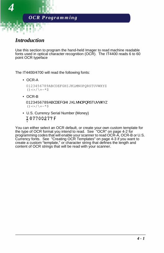
4
OCR ProgrammingIntroduction
Use this section to program the hand-held Imager to read machine readable fonts used in optical character recognition (OCR). The IT4400 reads 6 to 60 point OCR typeface
The IT4400/4700 will read the following fonts:
• OCR-A
0123456789ABCDEFGHIJKLMNOPQRSTUVWXYZ()<>/\+-*$
• OCR-B
0123456789ABCDEFGHIJKLMNOPQRSTUVWXYZ()<>/\+-*$
• U.S. Currency Serial Number (Money)
You can either select an OCR default, or create your own custom template for the type of OCR format you intend to read. See "OCR" on page 4-2 for programming codes that will enable your scanner to read OCR-A, OCR-B or U.S. Currency fonts. See "Creating OCR Templates" on page 4-3 if you want to create a custom “template,” or character string that defines the length and content of OCR strings that will be read with your scanner.
*
4 - 1

OCRDefault All OCR Settings turns off all OCR capability in the scanner, so the scanner will be able to scan linear, stacked, matrix, and composite bar codes, but not OCR fonts. In addition, any OCR templates you have created are erased. The 8 digit default templates are reinstated for any future use of the OCR On codes listed below.
< Default All OCR Settings >
OCR
OCR-A On allows you to scan characters in the OCR-A font. The default setting allows you to scan any 8 digit combination. If you have created an OCR template, character combinations that fit the template can be scanned (see "Creating an OCR Template"on page 4-3).
OCR-B On allows you to scan characters in the OCR-B font. The default setting allows you to scan any 8 digit combination. If you have created an OCR template, character combinations that fit the template can be scanned (see "Creating an OCR Template"on page 4-3).
U.S. Currency On allows you to scan characters in the font used on U.S. currency. The default setting allows you to scan any 8 digit combination. If you have created an OCR template, character combinations that fit the template can be scanned (see "Creating an OCR Template "on page 4-3).
OCR-A On
OCR-B On
U.S. Currency On
4 - 2
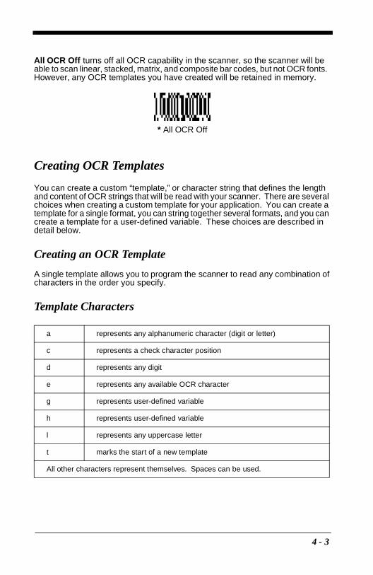
All OCR Off turns off all OCR capability in the scanner, so the scanner will be able to scan linear, stacked, matrix, and composite bar codes, but not OCR fonts. However, any OCR templates you have created will be retained in memory.
Creating OCR Templates
You can create a custom “template,” or character string that defines the length and content of OCR strings that will be read with your scanner. There are several choices when creating a custom template for your application. You can create a template for a single format, you can string together several formats, and you can create a template for a user-defined variable. These choices are described in detail below.
Creating an OCR Template
A single template allows you to program the scanner to read any combination of characters in the order you specify.
Template Characters
a represents any alphanumeric character (digit or letter)
c represents a check character position
d represents any digit
e represents any available OCR character
g represents user-defined variable
h represents user-defined variable
l represents any uppercase letter
t marks the start of a new template
All other characters represent themselves. Spaces can be used.
* All OCR Off
4 - 3

To Add an OCR Template
1. Begin building the template.Scan the Enter OCR Template symbol (page 4-7).
2. Scan the characters for the string.Use the Template Characters chart above to determine what characters you need to create your format. Use the Programming Chart (inside back cover) to scan the characters for your template.
Example A: You need to read any combination of 8 digits. The template:
dddddddd
To create this template, you would scan the Enter OCR Template symbol (page 4-7), then scan the “d” from the inside back cover 8 times. Scan Save OCR Template (page 4-8). This would let you read any string of 8 digits, for example:
37680981
3. Character Match SequencesOn the "Decimal to Hex to ASCII Conversion Chart" on page 2-34, find the Hex value that represents the character(s) you want to match. Use the Pro-gramming Chart (inside back cover) to scan the numbers that represent these characters.
Example B: You need to read 3 digits, 3 specific characters (ABC), 3 digits. The template:
ddd414243ddd
To create this template, you would scan the Enter OCR Template symbol (page 4-7), scan the “d” from the inside back cover 3 times, scan 414243 from the inside back cover (the hex characters for “A,” “B,” and “C”), then scan the “d” from the inside back cover 3 more times. Scan Save OCR Template (page 4-8). This would let you read any string of 3 digits, “ABC,” then any string of 3 digits, for example:
551ABC983
}
hex codes for letters A, B, and C
4 - 4

4. Adding SpacesYou may also need to put spaces in your template.
Example C: You need to read 3 digits, space, 3 specific characters (ABC), space, 3 digits. The template:
ddd2041424320ddd
To create this template, you would scan the Enter OCR Template symbol (page 4-7), scan the “d” from the inside back cover 3 times, scan 2041424320 from the inside back cover (the hex characters for “space,” “A,” “B,” “C,” “space”), then scan the “d” from the inside back cover 3 more times. Scan Save OCR Template (page 4-8). This would let you read any string of 3 digits, space, “ABC,” space, then any string of 3 digits, for example:
551 ABC 983
5. Exit OCR Template EditorScan Save OCR Template to save your entries. Discard OCR Template exits without saving any OCR Template changes.
Stringing Together Multiple Formats (Creating “Or” Statements)
You may want to program the scanner to accept many OCR formats. To do this, you would string together each format with a “t.” This tells the scanner to read optical characters that match any one of the formats in the template.
Example D: You need to read any combination of 8 digits, or a combination of 4 digits, 2 uppercase letters, and 2 digits. The template:
ddddddddtddddlldd
To create this template, you would scan the Enter OCR Template symbol (page 4-7), scan the “d” from the inside back cover 8 times, then scan the “t” to create the “or” statement. Then you would scan the characters for the 2nd template. Scan the “d” 4 times, scan “l” 2 times, then scan “d” 2 more times. Scan Save OCR Template (page 4-8). This would let you read either type of format, for example:
99028650or
9902XZ50
You can string together as many templates as you need.
hex code for a space
4 - 5

Creating a User-Defined Variable
You can create up to two of your own user variables for an OCR template. These variables will represent any OCR readable characters. The user-defined variables are stored under the letters “g” and “h.” Creating a user variable follows the same steps as creating a template, but instead of scanning the Enter OCR Template symbol, you scan the Enter User-Defined Variable symbol (page 4-7). The letters g and h can then be used in an OCR template to define the variable you specified.
Example E: You need a variable to represent the letters “A,” “B,” or “C.” The template for this variable:
414243
To create this template, you would scan the Enter User-Defined Variable “g” symbol (page 4-7). Scan 414243 from the inside back cover (the hex characters for “A,” “B,” and “C”). Scan Save OCR Template (page 4-8). This will let you read either A or B or C in any position where you place the g. For example, you could create the following template:
ddddddggg
This template would then let you read data that began with 6 digits, and had an A, B, or C trailing. So you would be able to read:
654321ABCor
654321BACor
654321CCC
Adding an OCR Check Character
You may want to program the scanner to read OCR strings that have a check character. The IT4400/4700 reads and strips out the OCR check character created using a modulo 10 or modulo 36 table. (Modulo 10 being digits 0-9, modulo 36 being digits 0-9 and characters A-Z.)
Scan the Modulo 10 or Modulo 36 Check Character bar code to specify the type of check character used in the OCR strings you’re scanning. The scanner will then only read OCR character strings with a valid check character. The IT4400/4700 transmits the OCR data without the check character data. You must specify the location of the check character in the template with a c.
4 - 6

Example F: You need to read any combination of 6 digits, with a modulo 10 check character in the 7th position. The template:
ddddddc
To create this template, you would scan the Modulo 10 Check Character symbol (page 4-7). Then scan the Enter OCR Template symbol, scan the “d” from the inside back cover 6 times, and scan the “c” once. Scan Save OCR Template (page 4-8). This template will let you read any combination of 6 digits with a correct check character after. (If the check character is invalid, the scanner will issue an error beep.) For example, the following string could be scanned:
0123455
and the output would be:012345
OCR Template Codes
† One or more two-digit numbers and Save are required after reading this programming symbol. Refer to the Programming Chart (inside back cover).
Enter OCR Template †
Enter User-Defined Variable
“h”
Enter User-Defined Variable
“g”
OCR Modulo 10 Check
Character OCR Modulo 36
Check Character
4 - 7

Exit Selections
Save OCR Template
Discard OCR Template
4 - 8
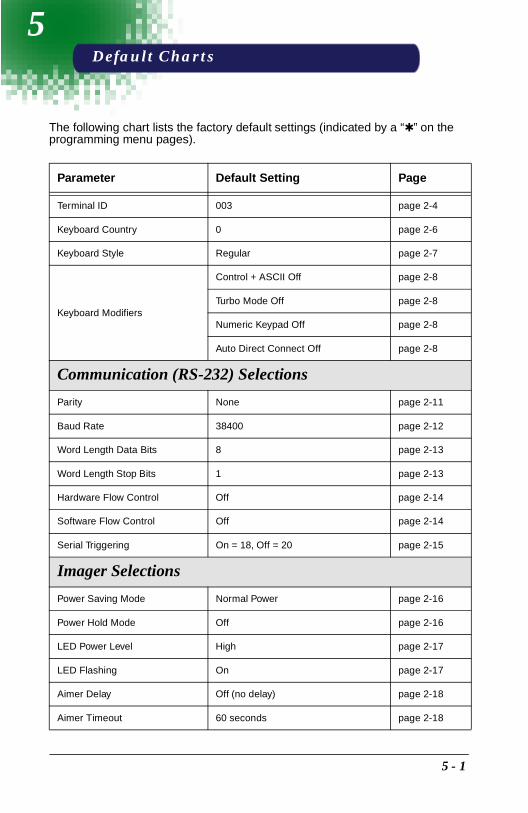
5
Default ChartsThe following chart lists the factory default settings (indicated by a “✱ ” on the programming menu pages).
Parameter Default Setting Page
Terminal ID 003 page 2-4
Keyboard Country 0 page 2-6
Keyboard Style Regular page 2-7
Keyboard Modifiers
Control + ASCII Off page 2-8
Turbo Mode Off page 2-8
Numeric Keypad Off page 2-8
Auto Direct Connect Off page 2-8
Communication (RS-232) Selections
Parity None page 2-11
Baud Rate 38400 page 2-12
Word Length Data Bits 8 page 2-13
Word Length Stop Bits 1 page 2-13
Hardware Flow Control Off page 2-14
Software Flow Control Off page 2-14
Serial Triggering On = 18, Off = 20 page 2-15
Imager Selections
Power Saving Mode Normal Power page 2-16
Power Hold Mode Off page 2-16
LED Power Level High page 2-17
LED Flashing On page 2-17
Aimer Delay Off (no delay) page 2-18
Aimer Timeout 60 seconds page 2-18
5 - 1
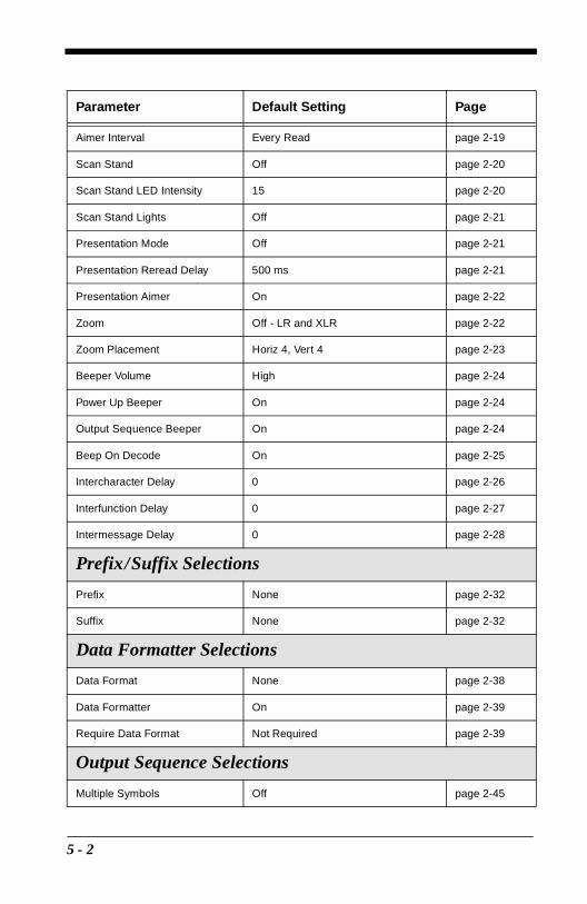
Aimer Interval Every Read page 2-19
Scan Stand Off page 2-20
Scan Stand LED Intensity 15 page 2-20
Scan Stand Lights Off page 2-21
Presentation Mode Off page 2-21
Presentation Reread Delay 500 ms page 2-21
Presentation Aimer On page 2-22
Zoom Off - LR and XLR page 2-22
Zoom Placement Horiz 4, Vert 4 page 2-23
Beeper Volume High page 2-24
Power Up Beeper On page 2-24
Output Sequence Beeper On page 2-24
Beep On Decode On page 2-25
Intercharacter Delay 0 page 2-26
Interfunction Delay 0 page 2-27
Intermessage Delay 0 page 2-28
Prefix/Suffix Selections
Prefix None page 2-32
Suffix None page 2-32
Data Formatter Selections
Data Format None page 2-38
Data Formatter On page 2-39
Require Data Format Not Required page 2-39
Output Sequence Selections
Multiple Symbols Off page 2-45
Parameter Default Setting Page
5 - 2
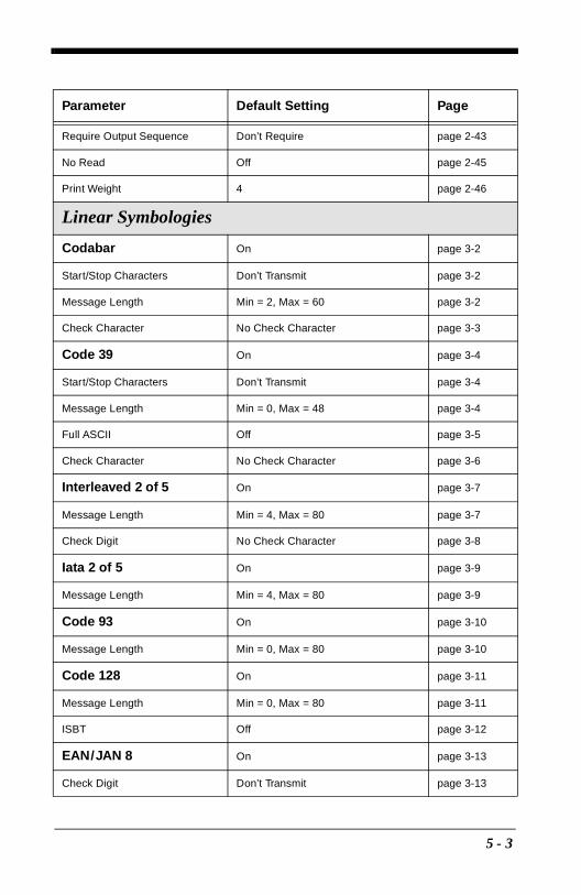
Require Output Sequence Don’t Require page 2-43
No Read Off page 2-45
Print Weight 4 page 2-46
Linear Symbologies
Codabar On page 3-2
Start/Stop Characters Don’t Transmit page 3-2
Message Length Min = 2, Max = 60 page 3-2
Check Character No Check Character page 3-3
Code 39 On page 3-4
Start/Stop Characters Don’t Transmit page 3-4
Message Length Min = 0, Max = 48 page 3-4
Full ASCII Off page 3-5
Check Character No Check Character page 3-6
Interleaved 2 of 5 On page 3-7
Message Length Min = 4, Max = 80 page 3-7
Check Digit No Check Character page 3-8
Iata 2 of 5 On page 3-9
Message Length Min = 4, Max = 80 page 3-9
Code 93 On page 3-10
Message Length Min = 0, Max = 80 page 3-10
Code 128 On page 3-11
Message Length Min = 0, Max = 80 page 3-11
ISBT Off page 3-12
EAN/JAN 8 On page 3-13
Check Digit Don’t Transmit page 3-13
Parameter Default Setting Page
5 - 3

EAN/JAN 13 On page 3-14
Check Digit Don’t Transmit page 3-14
UPC A On page 3-16
Check Digit Don’t Transmit page 3-16
Number System Transmit page 3-16
UPC E0 On page 3-17
Check Digit Don’t Transmit page 3-17
Number System Don’t Transmit page 3-17
Version E Expand Don’t Expand page 3-18
UPC E1 On page 3-18
UPC 2 Digit Addenda Off page 3-18
UPC 5 Digit Addenda Off page 3-18
RSS-14 On page 3-19
RSS-14 Limited On page 3-19
RSS-14 Expanded On page 3-20
RSS-14 Expanded Message Length
Min = 1, Max = 80 page 3-20
Codablock Off page 3-21
Message Length Min = 0, Max = 2048 page 3-21
PDF417 On page 3-22
Message Length Min = 1, Max = 2750 page 3-22
Micro PDF417 Off page 3-23
Message Length Min = 1, Max = 2750 page 3-23
Code 49 Off page 3-24
Message Length Min = 1, Max = 81 page 3-24
Parameter Default Setting Page
5 - 4

Composite Codes On page 3-25
Message Length Min = 1, Max = 300 page 3-25
Postal Symbology Selections
POSTNET Code (USPS) Off page 3-26
BPO 4 State Code Off page 3-26
Canadian 4 State Code Off page 3-26
Kix Code Off page 3-26
Australian 4 State Code Off page 3-27
Japanese Postal Service Off page 3-27
Planet Code Off page 3-27
2D Matrix Selections
QR Code On page 3-28
Message Length Min = 1, Max = 3500 page 3-28
Data Matrix On page 3-29
Message Length Min = 1, Max = 1500 page 3-29
MaxiCode On page 3-30
Message Length Min = 1, Max = 150 page 3-30
SCM Only Off page 3-31
Aztec Code On page 3-32
Message Length Min = 1, Max = 3750 page 3-32
VeriCode On page 3-33
VeriCode Size 0 or Off (all sizes on) page 3-34
Parameter Default Setting Page
5 - 5

5 - 6

6
Quick*ViewQuick*View Demonstration Software Instructions
Quick*View is a Microsoft Windows program that displays decoded symbol messages and captures images (for instance, ID photographs) from the IMAGETEAM 4400/4700 Imager. Bar code information and images are displayed in the Quick*View window.
Setting Up the Imager and the Quick*View Software
1. Connect the Imager to the PC’s com port (com port 1 or com port 2) via the appropriate interface cable.Connect the appropriate power supply to the Imager. (The Imager cannot get its power from the PC’s com port.)
For Microsoft Windows 95 or NT 4.0
2. Insert the Quick*View diskette labelled “32 Bit Release” into Drive A or B.
3. From the Start Menu, click on Run. Type “x:\setup” in the command line box, where “x” represents a drive letter, typically “A” for the 3.5" floppy drive on most PCs. Click on OK.
4. Follow the instructions in the setup screens.
5. To start the Quick*View program, from the Start Menu click on Programs, Quickview, QuickView (32 Bit).
For Microsoft Windows 3.1
2. Insert the Quick*View diskette labelled “16 Bit Release” into Drive A or B.
3. Copy the QV16.EXE file to your PC hard drive.
4. From the Program Manager, File Menu, Run the QV16.EXE file.
6 - 1

Installing Quick*View from the Web
1. Access the Welch Allyn DCD web site at http://dcd.welchallyn.com.
2. Click on the Support button, then click on the Software Download button.
3. When prompted, enter the user name: pumpkin and the password: pie
4. Locate the listing for Quick*View. Click on the yellow Download button.
5. When prompted, select Save File, and save the files to the c:\win-dows\temp directory.
6. Once you have finished downloading the file, exit the web site.
7. Using Explorer, go to the c:\windows\temp file.
8. Double click on the Quickview.exe file. Follow the screen prompts to install the Quick*View program.
9. To start Quick*View, from the Start Menu click on Programs, Quick*View, Quick*View.
Note: If you wish, you can create a shortcut to the Quick*View executable on your desktop.
Temporary Quick*Load Configuration
For a quick download communication configuration, scan the Quick*Load bar code and the scanner will be temporarily configured for Quick*Load settings.
Note: If you have a unit capable of keyboard wedge mode, scan the bar code below and the unit will communicate in RS-232 mode, allowing it to work with Quick*Load. To convert the scanner back to keyboard wedge communication, cycle the power.
Quick*Load
6 - 2

Using the Quick*View Software
Upon startup, the Quick*View splash screen appears for approximately three seconds. Quick*View will then attempt to establish communications with the Imager.
If Communication Cannot Be Established
This message appears if communication cannot be established:
Quick*View defaults to com 1 as the communications port. If you have plugged the Imager into another com port, you must Cancel out of this message.
Click on File - Preferences. This popup appears:
Click on the radio button for the appropriate com port, then click on OK. Quick*View should now be able to locate the Imager.
You may also need to pull the Imager’s trigger to establish communications between the PC and the Imager.
If you want Quick*View to search for the Imager and establish communication, click on Device - Auto Baud Detect.
6 - 3
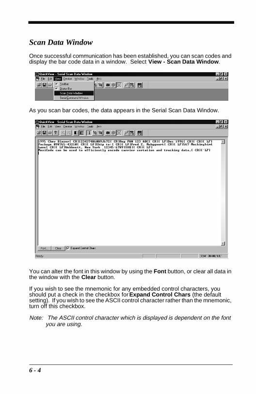
Scan Data Window
Once successful communication has been established, you can scan codes and display the bar code data in a window. Select View - Scan Data Window.
As you scan bar codes, the data appears in the Serial Scan Data Window.
You can alter the font in this window by using the Font button, or clear all data in the window with the Clear button.
If you wish to see the mnemonic for any embedded control characters, you should put a check in the checkbox for Expand Control Chars (the default setting). If you wish to see the ASCII control character rather than the mnemonic, turn off this checkbox.
Note: The ASCII control character which is displayed is dependent on the font you are using.
6 - 4
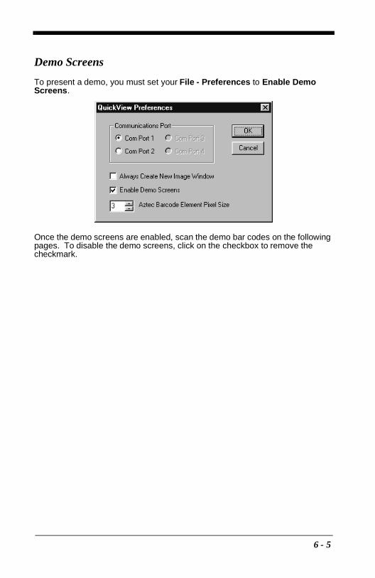
Demo Screens
To present a demo, you must set your File - Preferences to Enable Demo Screens.
Once the demo screens are enabled, scan the demo bar codes on the following pages. To disable the demo screens, click on the checkbox to remove the checkmark.
6 - 5

Electronic Parts Manufacturing Demonstration
The manufacturing industry represents the fastest growing market for high capacity bar codes by recognizing the long term benefits associated with having complete information on a product at all times. In this demonstration, high capacity codes are used to issue parts to a manufacturing floor. By using a high capacity code, complete information about the parts ensures that the right parts are issued and billed to the proper location. Welch Allyn offers both long-range and high-density models of the IMAGETEAM 4400 to provide the optimal hand held solution for a wide variety of manufacturing operations.
Scan each of the following bar codes to display sample screens for a manufacturing application.
3400/C-1234223-1234863-1234
440014221-9876971-9876
Data Matrix Codes QR Codes
3400/C-1234223-1234863-1234
440014221-9876971-9876
6 - 6

Shipping Demonstration
Note: This demonstration is appropriate for the 4400LR and 4700LR or only.
In an effort to reduce costs through distribution center automation, United Parcel Service (UPS) is printing a MaxiCode label on every package shipped worldwide. In this demonstration, the IMAGETEAM 4400 Imager provides a cost-effective solution for UPS personnel in hand sorting operations, and for customers who want to take advantage of the savings associated with MaxiCode without incurring the cost of an over-the-belt scanning solution.
Scan each of the following bar codes to display sample screens for a shipping application.
Ship To:
Cheryl IsomWelch Allyn4341 Jordan Road, Box 187Skaneateles Falls, NY 13153
Benjamin F. LynnMusket Co.243 Liberty ParkwayBoston, MA 02134
Welch Allyn4619 Jordan RoadSkaneateles Falls, NY 13153
Ship To:
Benjamin F. LynnMusket Co.243 Liberty ParkwayBoston, MA 02134
6 - 7

Patient Registration Demonstration
Health care professionals can use two-dimensional symbologies for patient applications. In this demonstration, patient registration information is encoded on an identification card that is scanned each time the patient arrives for treatment. Both the health care professional and the patient benefit from the enhanced accuracy, efficiency, and security that photo identification provides.
Scan each of the following bar codes to display sample screens for this type of patient application.
Patient ID:890-66-4589
Mason, Theresa F.5 Beach Front DrivePensacola, FL 49607
Patient ID:123-45-4569
Ely, Gerald S.5 Quarry Rd.Omaha, NE 12345
6 - 8

Bills of Lading Demonstration
Note: This demonstration is appropriate for the 4400LR and 4700LR only.
Multiple linear bar codes may be replaced in a bill of lading/inventory application. In this demonstration, an individual linear code would typically be used for each part number, description, and quantity, as well as for customer and order number information. If linear codes were used for the bill of lading shown below, the user would have to scan 14 individual bar codes before moving on to the next package.
By taking advantage of the enhanced data capacity of PDF417, the user is able to encode all the required information in a single bar code label. Using the Imager and a two-dimensional symbology, the user gets complete information in a single scan.
Scan this bar code to display a sample screen for this bill of lading application.
Order #: 99999 Welch Allyn4619 Jordan RoadBox 187Skaneateles Falls, NY 13153(315) 685-8945
Ship to:ABC Company123 Highway WestSan Diego, CA 92100
Customer #: 1234567890Pick Date: March 4, 1998
Part Number Description Quantity3000-12C 3000PDF 36720/B SCANNER 454/57/UG 54/57/UG 342204062 CABLE 1
6 - 9

Signature Capture Demonstration
Note: This demonstration is appropriate for the 4400LR and 4700LR only.
The signature capture demo is performed by scanning the Aztec bar code below the signature box. The Aztec bar code commands the scanner to capture the image of the signature box and its contents and send this image to the host system running Quick*View.
PAUL’S QUICK MARTMAIN ST.
NEW YORK, NEW YORK315-123-4567
1122-3344-5678
THU, MAR 04, 1999 09=34B
*** CREDIT CARD ***CARD NO: 00234567899876543EXP DATE: 0100CARD TYPE: MC - CREDITTR TYPE: SALEAPP CODE: 004910REC NO: C009
TOTAL: $37.99
Sign
6 - 10

Snapshot
You may also use the IMAGETEAM 4400/4700 to capture an image. Click on Device - Snapshot, or click on the camera icon in the button bar to activate this feature.
Select the resolution you wish to use for this image, either Full, Half or Quarter Resolution. (These can also be selected by clicking on the 1, 1/2, or 1/4 buttons in the button bar.)
Note: The higher resolution, the sharper the image, and the larger the size of the resulting file. Higher resolution images also take longer to process.
You must also select whether you wish to capture the image in Gray Scale or in Black & White.
Note: If you need to see exactly what the Imager sees (for example, if you are diagnosing a bar code), you should set the image to Black & White.
If you want the Imager to display illuminated aiming brackets, click on Device - Snapshot Properties - Use Aimer During Image Capture, or click on the aimer icon in the button bar.
Snapshoticon
Resolutionicons
Black & White
Gray Scale
Aimericon
6 - 11

Snapshot, continued
Pull the Imager’s trigger to capture an image. Captured images appear in the Quick*View window.
As you move the mouse over the image, the cursor changes to a magnifying glass. Left click to zoom in to the image, right click to zoom out.
Saving an Image File
If you wish to save the file as a bitmap, click on File - Save As. Enter the location and file name you wish to use for this file. Click on Save and a bitmap file will be saved.
6 - 12

Open Com Port
If you wish to open a com port which does not have a device attached, you can do so by selecting File - Open Com Port.
This dialog box appears:
Click on the arrows to select the Baud Rate, Parity, and Data Bits for the com port you wish to open. Click on Open Port and Quick*View opens the com port whether or not there is a device attached. This feature may be beneficial when troubleshooting a device.
Reporting Firmware Revision
To find out what software version the Imager is using, click on Device - Report Device Firmware Revision, or click on the Imager icon in the button bar.
This popup lists the firmware information:
Imagericon
6 - 13

Load New Imager Software
If you need to upgrade the Imager’s software, you can load a new software file into the Imager’s ROM. Click on Device - Load Firmware File into ROM or click on the lightning flash icon in the button bar.
You will be prompted for the name of the hex file:
Select the hex file and click on Open. Quick*View will flash the new software into your Imager’s ROM.
Imager Power Settings
By default, the Imager will power down after 2 minutes of inactivity. If you wish to keep the Imager powered up indefinitely, click on Device - Hold Power. To reset the Imager to the default power setting, click on Device - Remove Power Hold.
Trigger Settings
If you wish to control the Imager’s trigger with the software, you can select Device - Trigger On, or Device - Trigger Off. These settings turn the trigger on and off just as if you were holding the trigger or releasing it manually. This feature may be necessary when working with a fixed device that has no trigger.
Flashicon
6 - 14

RS-232 Serial Commands
Click on View - Serial Command Window to display the Command Center window which allows you to enter serial commands to the Imager. Click on View - Scan Data Window to open a window which displays serial data in a text format.
Serial commands are used to program the Imager and to query the Imager about programming parameters. The serial programming commands are listed beginning on page 6-17. Information about performing queries is listed on page page 6-28.
Serial Programming Commands
The serial programming commands can be used in place of the programming bar codes listed in Section 2. Both the serial commands and the programming bar codes will program the Imager. For complete descriptions and examples of each programming command, refer to Section 2.
To enter a serial command, click in the Enter Menu Command text box and type in the command(s) you wish to use. If you are typing in more than one command, separate the commands with a semicolon (;). Click on Send Command to send the command(s) to the Imager.
6 - 15
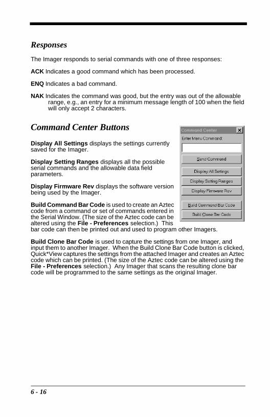
Responses
The Imager responds to serial commands with one of three responses:
ACK Indicates a good command which has been processed.
ENQ Indicates a bad command.
NAK Indicates the command was good, but the entry was out of the allowable range, e.g., an entry for a minimum message length of 100 when the field will only accept 2 characters.
Command Center Buttons
Display All Settings displays the settings currently saved for the Imager.
Display Setting Ranges displays all the possible serial commands and the allowable data field parameters.
Display Firmware Rev displays the software version being used by the Imager.
Build Command Bar Code is used to create an Aztec code from a command or set of commands entered in the Serial Window. (The size of the Aztec code can be altered using the File - Preferences selection.) This bar code can then be printed out and used to program other Imagers.
Build Clone Bar Code is used to capture the settings from one Imager, and input them to another Imager. When the Build Clone Bar Code button is clicked, Quick*View captures the settings from the attached Imager and creates an Aztec code which can be printed. (The size of the Aztec code can be altered using the File - Preferences selection.) Any Imager that scans the resulting clone bar code will be programmed to the same settings as the original Imager.
6 - 16

Serial Programming Commands
Selection Setting Serial Command
Factory Default Settings
HD DEFALT;MXZOOM1.
HD10DEFALT;MXZOOM1;MXZTOP6.
LR/XLR DEFALT.
Status CheckShow Software Revision REV?.
Show Data Formats DFMBK3?.
Enable All Symbologies ALLENA1.
Disable All Symbologies ALLENA0.
Output SelectionsPower PC Revision REVMPC.
Boot Code Revision REV_BT.
Terminal ID TERMID.
Keyboard Country KBDCTY.
Keyboard Style
Regular KBDSTY0.
Caps Lock KBDSTY1.
Shift Lock KBDSTY2.
Emulate ExternalKeyboard
KBDSTY5.
Automatic Caps Lock KBDSTY6.
Keyboard Modifiers
*Control + ASCII Off KBDCAS0.
Control + ASCII On KBDCAS1.
*Turbo Mode Off KBDTMD0.
Turbo Mode On KBDTMD1.
*Numeric Keypad Off KBDNPS0.
Numeric Keypad On KBDNPS1.
*Auto Direct Conn. Off KBDADC0.
Auto Direct Conn. On KBDADC1.
6 - 17

Communication Settings*Default All RS-232 Communication Settings
232DFT.
Parity
*None 232PARN.
Mark 232PARM.
Space 232PARS.
Odd 232PARO.
Even 232PARE.
Baud Rate
*38400 BPS 232BDR38400.
300 BPS 232BDR300.
600 BPS 232BDR600.
1200 BPS 232BDR1200.
2400 BPS 232BDR2400.
4800 BPS 232BDR4800.
9600 BPS 232BDR9600.
19200 BPS 232BDR19200.
57600 BPS 232BDR57600.
115200 BPS 232BDR115200.
Word Length Data Bits*8 Data Bits 232LEN8.
7 Data Bits 232LEN7.
Word Length Stop Bits*1 Stop Bit 232STP1.
2 Stop Bits 232STP2.
Hardware Flow Control*Disable 232CTS0.
Enable 232CTS1.
Software Flow Control*Disable 232SFL0.
Enable 232SFL1.
Serial Triggering
*Disable TRGSER0.
Enable TRGSER1.
*Trigger Defaults TRGDFT.
Trigger On TRG_ON.
Trigger Off TRGOFF.
Selection Setting Serial Command
6 - 18

Imager Selections
Power Saving Mode
*Normal PowerPWRDFT;SCNLEDHIGH;HSTSSS0.
Low PowerPWRTIM0,TRG0,IMG1;SCNLEDLOW;HSTSSS1.
Medium Power
PWRTIM10000,TRG0,IMG1;SCNLEDHIGH;HSTSSS0.
Power Hold ModeOn PWR_ON1.
*Off PWR_ON0.
LED Power
*High SCNLEDHIGH.
Off SCNLEDOFF.
Low SCNLEDLOW.
LED Flashing *On HSTLED0.
Off HSTLED1.
Aimer Delay
*Off (no delay) HSTAIM0.
200 milliseconds HSTAIM200.
400 milliseconds HSTAIM400.
Aimer Timeout Set Timeout HSTTIM.
Aimer Interval
*Every Read HSTINT1.
Every 2nd Read HSTINT2.
Every 3rd Read HSTINT3.
Every “x” Read HSTINT.
Off HSTINT0.
Scan Stand*Off SSTMOD0.
On SSTMOD1.
Scan Stand LED Intensity 15 SSTFRQ.
Scan Stand LightsOn SSTLON1.
*Off SSTLON0.
Presentation ModeOn PRSMOD1.
*Off PRSMOD0.
Presentation Reread Delay 500 ms PRSTIM.
Presentation Default PRSDFT.
Selection Setting Serial Command
6 - 19

Presentation Aimer*On PRSAIM1.
Off PRSAIM0.
ZoomDisable MXZOOM0.
Enable MXZOOM1.
Zoom PlacementVertical MXZTOP.
Horizontal MXZSID.
Output Selections
Beeper Volume
*High BEPVOL50.
Medium BEPVOL25.
Low BEPVOL5.
Off BEPVOL0.
Power Up Beeper*Enable BEPRST1.
Disable BEPRST0.
Output Sequence Beeper*On BEPCLK1.
Off BEPCLK0.
Beep On Decode *On BEPDEC1.
Off BEPDEC0.
Beeper Default BEPDFT.
Intercharacter Delay DLYCHR.
User Specified Intercharacter Delay
Character DLY_XX.
Length DLYCRX.
Interfunction Delay DLYFNC.
Intermessage Delay DLYMSG.
Prefix/Suffix SelectionsAdd CR Suffix to All Symbologies SUFBK299CR.
Add Code I.D. Prefix to All Symbologies PREBK2995C80.
Add AIM I.D. Prefix to All Symbologies PREBK2995C81.
Prefix
Add Prefix PREBK2.
Clear One Prefix PRECL2.
Clear All Prefixes PRECA2.
Save Current Prefix Changes MNUSAV.
Discard Current Prefix Changes MNUABT.
Suffix
Add Suffix SUFBK2.
Clear One Suffix SUFCL2.
Clear All Suffixes SUFCA2.
Selection Setting Serial Command
6 - 20

Save Current Suffix Changes MNUSAV.
Discard Current Suffix Changes MNUABT.
Data Formatter Selections
Data Format Editor
*No Format DFMDF3.
Enter Format DFMBK3.
Clear One Format DFMCL3.
Clear All Formats DFMCA3.
Save Current Data Format Changes MNUSAV.
Discard Current Data Format Changes MNUABT.
Data Formatter*Enable DFM_EN1.
Disable DFM_EN0.
Require Data Format Require DFM_EN2.
Show Data Formats DFMBK3?.
Alternate Data Formats
1 VSAF_1.
2 VSAF_2.
3 VSAF_3.
Output Sequence Selections
Require Output Sequence
Require SEQ_EN2.
On/Not Required SEQ_EN1.
Off SEQ_EN0.
Output Sequence Editor*Default Sequence SEQDFT.
Enter Sequence SEQBLK.
Save Current Sequence Changes MNUSAV.
Discard Current Sequence Changes MNUABT.
Multiple Symbols*Disable SEQ_EN0.
Enable SEQ_EN1.
No Read *Disable SHWNRD0.
Enable SHWNRD1.
Print Weight Default PRTWGT4.
Set Print Weight PRTWGT.
Linear Symbology Selections
Codabar*Default All Codabar Settings*
CBRDFT.
Codabar*On CBRENA1.
Off CBRENA0.
Selection Setting Serial Command
6 - 21

Codabar Start/Stop Char.*Don’t Transmit CBRSSX0.
Transmit CBRSSX1.
Codabar Message LengthMinimum CBRMIN.
Maximum CBRMAX.
Codabar Check Char.
*No Check Char. CBRCHK0,CKX0.
Validate, But Don’t Transmit
CBRCHK1,CKX0.
Validate, and Transmit
CBRCHK1,CKX1.
Code 39*Default All Code 39 Settings*
C39DFT.
Code 39*On C39ENA1.
Off C39ENA0.
Code 39 Start/Stop Char.*Don’t Transmit C39SSX0.
Transmit C39SSX1.
Code 39 Full ASCII*Disable C39ASC0.
Enable C39ASC1.
Code 39 Message LengthMinimum C39MIN.
Maximum C39MAX.
Code 39 Check Char.
*No Check Char. C39CHK0,CKX0.
Validate, But Don’t Transmit
C39CHK1,CKX0.
Validate, and Transmit
C39CHK1,CKX1.
Interleaved 2 of 5*Default All Interleaved2 of 5 Settings*
I25DFT.
Interleaved 2 of 5*On I25ENA1.
Off I25ENA0.
Interleaved 2 of 5 Message Length
Minimum I25MIN.
Maximum I25MAX.
Interleaved 2 of 5 Check Digit
*No Check Char. I25CHK0,CKX0.
Validate, But Don’t Transmit
I25CHK1,CKX0.
Validate, and Transmit
I25CHK1,CKX1.
Iata 2 of 5*Default All Iata2 of 5 Settings*
A25DFT.
Selection Setting Serial Command
6 - 22

Iata 2 of 5*On A25ENA1.
Off A25ENA0.
Iata 2 of 5 Message LengthMinimum A25MIN.
Maximum A25MAX.
Code 93*Default All Code 93 Settings*
C93DFT.
Code 93*On C93ENA1.
Off C93ENA0.
Code 93 Message LengthMinimum C93MIN.
Maximum C93MAX.
Code 128*Default All Code 128Settings*
128DFT.
Code 128*On 128ENA1.
Off 128ENA0.
Code 128 Message LengthMinimum 128MIN.
Maximum 128MAX.
Code 128 Include *Disable 128FNC0.
Code 128 ISBT*Disable ISBENA0.
Enable ISBENA1.
EAN/JAN 8*Default All EAN/JAN 8 Settings*
EA8DFT.
EAN/JAN 8*On EA8ENA1.
Off EA8ENA0.
EAN/JAN 8 Check Digit*Don’t Transmit EA8CKX0.
Transmit EA8CKX1.
EAN/JAN 13*Default All EAN/JAN 13 Settings*
E13DFT.
EAN/JAN 13*On E13ENA1.
Off E13ENA0.
EAN/JAN 13 Check Digit*Don’t Transmit E13CKX0.
Transmit E13CKX1.
EAN/JAN 2 Digit AddendaOn EANAD21.
Off EANAD20.
EAN/JAN 5 Digit AddendaOn EANAD51.
Off EANAD50.
UPC A*Default All UPC A Settings*
UPADFT.
Selection Setting Serial Command
6 - 23

UPC A*On UPAENA1.
Off UPAENA0.
UPC A Check Digit*Don’t Transmit UPACKX0.
Transmit UPACKX1.
UPC A Number SystemDon’t Transmit UPANSX0.
*Transmit UPANSX1.
UPC E0*Default All UPC E0 Settings*
UE0DFT.
UPC E0*On UE0ENA1.
Off UE0ENA0.
UPC E0 Check Digit*Don’t Transmit UE0CKX0.
Transmit UE0CKX1.
UPC E0 Number System*Don’t Transmit UE0NSX0.
Transmit UE0NSX1.
UPC E0 Version E Expand*Don’t Expand UE0EXP0.
Expand UE0EXP1.
UPC E1*On UE1ENA1.
Off UE1ENA0.
UPC 2 Digit AddendaOn UPCAD21.
Off UPCAD20.
UPC 5 Digit AddendaOn UPCAD51.
Off UPCAD50.
RSS-14*Default All RSS-14 Settings*
RSSDFT.
RSS-14*On RSSENA1.
Off RSSENA0.
RSS-14 Limited*Default All RSS-14Limited Settings*
RSLDFT.
RSS-14 Limited*On RSLENA1.
Off RSLENA0.
RSS-14 Limited*Default All RSS-14Expanded Settings*
RSEDFT.
RSS Expanded*On RSEENA1.
Off RSEENA0.
RSS Expanded Msg. LengthMinimum RSEMIN.
Maximum RSEMAX.
Selection Setting Serial Command
6 - 24

Stacked Symbology Selections
Codablock*Default All Codablock Set-tings*
CBFDFT.
CodablockOn CBFENA1.
*Off CBFENA0.
CodablockMsg. Length
Minimum CBFMIN.
Maximum CBFMAX.
PDF417*Default All PDF417Settings*
PDFDFT.
PDF417*On PDFENA1.
Off PDFENA0.
PDF417 Message LengthMinimum PDFMIN.
Maximum PDFMAX.
Micro PDF417*Default All Micro PDFSettings*
MPDDFT.
Micro PDF417On MPDENA1.
*Off MPDENA0.
Micro PDF417 Message Length
Minimum MPDMIN.
Maximum MPDMAX.
Code 49*Default All Code 49Settings*
C49DFT.
Code 49On C49ENA1.
*Off C49ENA0.
Code 49 Msg. LengthMinimum C49MIN.
Maximum C49MAX.
Composite Codes*On COMENA1.
Off COMENA0.
Composite Msg. LengthMinimum COMMIN.
Maximum COMMAX.
Postal Symbology Selections
POSTNET Code (USPS)*On NETENA1.
Off NETENA0.
POSTNET Check Digit*Don’t Transmit NETCKX0.
Transmit NETCKX1.
BPO 4 State Code (BPO)On BPOENA1.
*Off BPOENA0.
Selection Setting Serial Command
6 - 25

Canadian 4 State CodeOn CANENA1.
*Off CANENA0.
Kix Code*Off KIXENA0.
On KIXENA1.
Australian 4 State CodeOn AUSENA1.
*Off AUSENA0.
Japanese Postal CodeOn JAPENA1.
*Off JAPENA0.
Planet CodeOn PLENA0.
*Off PLENA1.
2D Matrix Symbology Selections
QR Code Settings*Default All QR CodeSettings*
QRCDFT.
QR Code*On QRCENA1.
Off QRCENA0.
QR Code Message LengthMinimum QRCMIN.
Maximum QRCMAX.
Data Matrix Settings*Default All DataMatrix Settings*
IDMDFT.
Data Matrix*On IDMENA1.
Off IDMENA0.
Data Matrix Msg. LengthMinimum IDMMIN.
Maximum IDMMAX.
MaxiCode Settings*Default All MaxiCode Settings*
MAXDFT.
MaxiCode*On MAXENA1.
Off MAXENA0.
MaxiCode Msg. LengthMinimum MAXMIN.
Maximum MAXMAX.
SCM Only*Disable MAXSCM0.
Enable MAXSCM1.
Aztec Code Settings*Default All Aztec
Code Settings* AZTDFT.
Aztec Code*On AZTENA1.
Off AZTENA0.
Selection Setting Serial Command
6 - 26

1 VeriCode settings are not available in the standard Imager. An Imager with VeriCode setting capability can be special ordered from the factory.
Aztec Code Msg. LengthMinimum AZTMIN.
Maximum AZTMAX.
1VeriCode Settings*Default All VeriCodeSettings*
VERDFT.
1VeriCode*On VERENA1.
Off VERENA0.
1VeriCode Size
Size A VERSZA.
Size B VERSZB.
Size C VERSZC.
Size D VERSZD.
Size E VERSZE.
Test Menu*Off TSTMNU0.
On TSTMNU1.
2D Scan Diagnostics*Off 2DDIAG0.
On 2DDIAG1.
Selection Setting Serial Command
6 - 27

Query Commands
Several special characters can be used to query the Imager about its settings.
^ What is the default value for the setting(s).
? What is the Imager’s current value for the setting(s).
* What is the range of possible values for the setting(s). (The Imager’s response uses a dash (-) to indicate a continuous range of values. A pipe (|) separates items in a list of non-continuous values.)
Examples of Query Commands
Example #1:What is the range of possible values for Codabar Coding Enable?Enter: cbrena*.Response: CBRENA0-1[ACK]This response indicates that Codabar Coding Enable (CBRENA) has a range of values from 0 to 1 (off and on).
Example #2: What is the default value for Codabar Coding Enable?Enter: cbrena^.Response: CBRENA1[ACK]This response indicates that the default setting for Codabar Coding Enable (CBRENA) is 1, or on.
Example #3: What is the Imager’s current setting for Codabar Coding Enable?Enter: cbrena?.Response: CBRENA1[ACK]This response indicates that the Imager’s Codabar Coding Enable (CBRENA) is set to 1, or on.
6 - 28

Example #4: What are the Imager’s settings for all Codabar selections?Enter: cbr?.Response: CBRENA1[ACK],
CHK0[ACK],CKX0[ACK],SSX0[ACK],MIN2[ACK],MAX60[ACK],DFT[ACK].
This response indicates that the Imager’s Codabar Coding Enable (CBRENA) is set to 1, or on; the Check Character (CHK and CKX) is set to 0, or No Check Character; the Start/Stop Character is set to 0, or Don’t Transmit; the Minimum Message Length (MIN) is 2 characters; the Maximum Message Length (MAX) is 60 characters; and the Default setting (DFT) has no value.
Button Bar
The Quick*View button bar and the button functions are shown below.
*This icon only appears if you have Visual Menu software installed. Visual Menu is available free of charge from the Welch Allyn website at http:\\dcd.welchallyn.com/techsprt/download/software.htm.
Full HalfQuarter Resolution
Capture an image
Open file
Save file
Display Quick*View information
Print active file
Zoom out image
Zoom in image
Capture gray scale image
Capture black & white image
Display firmware revision
Flash a hex file into ROM
Cancel image capture
Display aimer
Start Visual Menu software*
6 - 29

6 - 30

7
Visual MenuVisual Menu Introduction
Visual Menu provides the ability to configure a scanning device by connecting the scanner to the com port of a PC. Visual Menu allows you to download upgrades to a scanner’s firmware, change programmed parameters, and create and print programming bar codes. Using Visual Menu, you can even set up the configuration for a scanner which is not attached to your PC. This enables one expert user to establish the configuration settings for all the devices your company uses, then save these configuration files for others. A configuration file can be e-mailed or, if you prefer, an expert user can create a bar code (or series of bar codes) which contains all the customized programming parameters, and mail or fax the bar code(s) to any location. Users in other locations can scan the bar code(s) to load in the customized parameters.
To communicate with a scanner, Visual Menu requires that the PC have at least one available serial communication port and an RS-232 cable to connect the port to the device. A power supply, which plugs into the cable, is also required.
Visual Menu Operations
The Visual Menu program performs the following operations:
• Displays all configuration data, and saves the information to a file on your PC.
• Configures the device to meet your specific requirements. Visual Menu has all the programming parameters which are available via programming bar codes in this User’s Guide.
• Creates and prints a clone bar code which contains the program and configuration data from one device. This bar code can then be used to program additional devices with the same parameters.
• Selects a device from a list, then performs offline or online file configuration for that device.
7 - 1

Temporary Visual Menu Configuration
For quick download communication configuration, scan the Visual Menu bar code to temporarily configure the scanner for Visual Menu settings.
Note: If you have a unit capable of keyboard wedge mode, scan the bar code below and the unit will communicate in RS-232 mode, allowing it to work with Visual Menu. To convert the scanner back to keyboard wedge communication, cycle the power.
Installing Visual Menu from the Web
10. Access the Welch Allyn DCD web site at http://dcd.welchallyn.com.
11. Click on the Support button, then click on the Software Download button.
12. When prompted, enter the user name: pumpkin and the password: pie
13. Locate the listing for Visual Menu. Click on the yellow Download button.
14. When prompted, select Save File, and save the files to the c:\win-dows\temp directory.
15. Once you have finished downloading the file, exit the web site.
16. Using Explorer, go to the c:\windows\temp file.
17. Double click on the Visualmenu.exe file. Follow the screen prompts to install the Visual Menu program.
18. To start Visual Menu, from the Start Menu click on Programs, Visual Menu, Visual Menu.
Note: If you wish, you can create a shortcut to the Visual Menu executable on your desktop.
Visual Menu
7 - 2
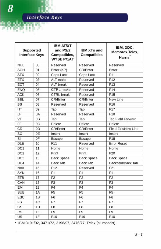
8
Interface KeysSupported Interface Keys
IBM AT/XT and PS/2
Compatibles, WYSE PC/AT
IBM XTs and Compatibles
IBM, DDC, Memorex Telex,
Harris*
* IBM 3191/92, 3471/72, 3196/97, 3476/77, Telex (all models)
NUL 00 Reserved Reserved ReservedSOH 01 Enter (KP) CR/Enter EnterSTX 02 Caps Lock Caps Lock F11ETX 03 ALT make Reserved F12EOT 04 ALT break Reserved F13
ENQ 05 CTRL make Reserved F14ACK 06 CTRL break Reserved F15BEL 07 CR/Enter CR/Enter New LineBS 08 Reserved Reserved F16HT 09 Tab Tab F17LF 0A Reserved Reserved F18VT 0B Tab Tab Tab/Field ForwardFF 0C Delete Delete DeleteCR 0D CR/Enter CR/Enter Field Exit/New LineSO 0E Insert Insert InsertSI 0F Escape Escape F19DLE 10 F11 Reserved Error ResetDC1 11 Home Home HomeDC2 12 Print Print F20DC3 13 Back Space Back Space Back SpaceDC4 14 Back Tab Back Tab Backfield/Back TabNAK 15 F12 Reserved F21SYN 16 F1 F1 F1ETB 17 F2 F2 F2CAN 18 F3 F3 F3EM 19 F4 F4 F4SUB 1A F5 F5 F5ESC 1B F6 F6 F6FS 1C F7 F7 F7GS 1D F8 F8 F8RS 1E F9 F9 F9US 1F F10 F10 F10
8 - 1

Supported Interface Keys
IBM, Memorex Telex (102)*
* IBM 3196/97, 3476/77, 3191/92, 3471/72, Memorex Telex (all mod-els) with 102 key keyboards
Memorex Telex (88)**
** Memorex Telex with 88 key keyboards
NUL 00 Reserved ReservedSOH 01 Enter EnterSTX 02 F11 PF10ETX 03 F12 PF11EOT 04 F13 PF12
ENQ 05 F14 ReservedACK 06 F15 ReservedBEL 07 New Line New LineBS 08 F16 Field ForwardHT 09 F17 Field ForwardLF 0A F18 ReservedVT 0B Tab/Field Forward Field ForwardFF 0C Delete DeleteCR 0D Field Exit New LineSO 0E Insert InsertSI 0F Clear EraseDLE 10 Error Reset Error Reset
DC1 11 Home ReservedDC2 12 Print PrintDC3 13 Back Space Back SpaceDC4 14 Back Tab Back FieldNAK 15 F19 ReservedSYN 16 F1 PF1ETB 17 F2 PF2CAN 18 F3 PF3EM 19 F4 PF4SUB 1A F5 PF5ESC 1B F6 PF6FS 1C F7 PF7GS 1D F8 PF8RS 1E F9 PF9US 1F F10 Home
8 - 2
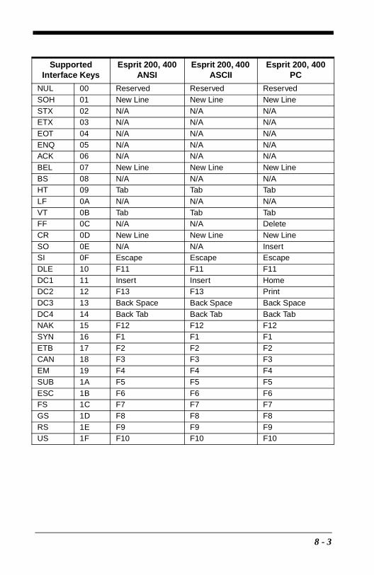
Supported Interface Keys
Esprit 200, 400 ANSI
Esprit 200, 400 ASCII
Esprit 200, 400 PC
NUL 00 Reserved Reserved ReservedSOH 01 New Line New Line New LineSTX 02 N/A N/A N/AETX 03 N/A N/A N/AEOT 04 N/A N/A N/AENQ 05 N/A N/A N/AACK 06 N/A N/A N/ABEL 07 New Line New Line New LineBS 08 N/A N/A N/AHT 09 Tab Tab TabLF 0A N/A N/A N/AVT 0B Tab Tab TabFF 0C N/A N/A DeleteCR 0D New Line New Line New LineSO 0E N/A N/A InsertSI 0F Escape Escape EscapeDLE 10 F11 F11 F11DC1 11 Insert Insert HomeDC2 12 F13 F13 PrintDC3 13 Back Space Back Space Back SpaceDC4 14 Back Tab Back Tab Back TabNAK 15 F12 F12 F12SYN 16 F1 F1 F1ETB 17 F2 F2 F2CAN 18 F3 F3 F3EM 19 F4 F4 F4SUB 1A F5 F5 F5ESC 1B F6 F6 F6FS 1C F7 F7 F7GS 1D F8 F8 F8RS 1E F9 F9 F9US 1F F10 F10 F10
8 - 3

8 - 4

9
Product Specifications & PinoutsProduct Specifications
Parameter Specification
DimensionsLength
Height
Width
6.1 inches (15.4 cm) (4400)4.85 inches (4.7 cm) (4700)5.6 inches (14.2 cm) (4400)1.85 inches (4.7 cm) (4700)2.5 inches (6.3 cm) (4400 and 4700)
Weight Less than 7.5 ounces (213 g), without cable
Illumination Source 660 nm (±30 nm) illumination LEDs
Aiming Pattern Source 670 nm laser light, <1.0 mW
Focal Point (focus)Long RangeHigh DensityHigh Density10
5 inches (12.7 cm) from Imager’s nose2 inches (5.1 cm) from Imager’s nose3 inches (7.62 cm) from Imager’s nose
Depth of FieldLong RangeLong Range OCRHigh DensityHigh Density10High Density OCR
2.0 to 9.0 inches (5.1 to 22.9 cm)2.7 to 9 inches (6.8 to 22.9 cm)1.7 to 2.4 inches (4.3 to 6.1 cm)2.0 to 4.0 inches (5.1 to 10.2 cm)1.5 to 4.6 inches (3.8 to 11.7 cm)
Field of ViewLong Range
High Density
High Density10
1 by 1.3 inches (2.54 by 3.3 cm) to 3.7 by 5.2 inches (9.4 by 13.2 cm)0.6 by 0.8 inches (1.5 by 2.0 cm) to 1.3 by 1.8 inches (3.3 by 4.6 cm)1 by 1.3 inches (2.5 by 3.3 cm) to 2.25 by 3 inches (5.7 by 7.6 cm)
ResolutionLong Range
Long Range OCRHigh Density
High Density10
High Density OCR
10 mil minimum, Linear symbol15 mil minimum, 2D Matrix symbol6 point (20 cpi) OCR text4 mil minimum, Linear symbol6.6 mil minimum, 2D Matrix symbol5 mil minimum Linear10 mil minimum 2D Matrix symbol6 point (20 cpi) OCR text
Rotational SensitivityOCR Text
360° around optical axis85° around optical axis
Viewing AngleOCR Text
±35° at the nominal operating distance±25°
Motion Sensitivity approx. 2 inches (5 cm) per second of lateral motion
9 - 1

Ambient Light Total darkness to 100,000 Lux (sunlight)
Video Image 8-bits per pixel
Operating Voltage 5.0 VDC - 14.0 VDC (with cable)
Current Draw - 4400Low Power ModeMedium Power ModeHigh Power Mode
.9 A average @ 5 VDC1 A average @ 5 VDC1.2 A average @ 5 VDC
Current Draw - 4700Low Power ModeMedium Power ModeHigh Power Mode
330 mA average @ 5 VDC430 mA average @ 5 VDC620 mA average @ 5 VDC
Noise Immunity 100 mV peak to peak
Temperature Ranges Operating 32° F to +122° F (-0C to +50C)Storage -40° F to +158° F (-40C to +70C)
Humidity 95% RH non-condensing, at +50° C
Mechanical Shock 10 drops from 5 feet (1.5 m) to concrete
ESD Sensitivity 15 kV to any external surface
Agency Compliance
FCC Class BCanadian Class BCE DOC Class BCDRH Class IICDRH/IEC Class 2UL/CUL Listed to UL1950 CSA 22.2 950TUV Certified to EN60950 and EN 60825-1 Class 2CTick
Parameter Specification
9 - 2

Cable Pinouts
RS-232 Output, external power (IT4400 and IT4700)
Decoded output data format is provided at the modular connector in the Imager.Interface cables normally supplied with the Imager are terminated with a 10 pin modular plug (P1) and a 9 pin Type D connector (P3) that is compatible with all Welch Allyn decoders and terminals. See chart below.
P1Pin 1 Pin 10
P39 Pin Type D Female
P3 connects to your terminal.
69
15
View A-A
P2 Power Pig TailP2 connects to
the external power supply.
Inner Outer
View B-B
10 Pin Modular PlugP1 connects to the Imager.
Inner
Outer
P2|0
532
87
SH
RedBlackGreen
BlueBrown
1 NC No Connection2 Ground Supply Ground3 +5VDC Power Connection4 Ground Supply Ground5 RXD Receive Data - Serial Data to Imager6 TXD Transmit Data - Serial Data from Imager7 +5VDC Power Connection8 RTS Request to Send Data9 CTS Clear to Send Data
10 TRIG External Trigger (IT4700 only)1
SH Drain Wire (Shield)
1. The HHLC mode is not available on an IT4700 with external trigger capability. Con-tact the factory if you require HHLC capability for an IT4700.
9 - 3

IT4400 Dimensions
6.06 in[15.38 cm]
2.49 in[6.32 cm]
Top View
Front View
5.62 in[14.28 cm]
1.53 in[4.01 cm]
1.07 in[2.72 cm]
3/4 View
Side View
9 - 4

IT4700 Dimensions4.83 in.
(12.27 cm)
2.49 in.(6.32 cm) Top View
Front View
Side View
Bottom View
1.83 in.(4.65 cm)
1.63 in.(4.14 cm)
1.53 in.(4.01 cm)
1.076 in.(2.73 cm)
.538 in.(1.37 cm)
.630 in.(1.60 cm)
M4 threaded insert .25 in. (6.35 mm) depth
9 - 5

9 - 6

10
Maintenance & TroubleshootingRepairs
Repairs and/or upgrades are not to be performed on this product. These services are to be performed only by an authorized service center. See page 11-1 for further information.
Maintenance
The IMAGETEAM 4400/IT4700 Imager provides reliable and efficient operation with a minimum of care. Although specific maintenance is not required, the following periodic checks ensure dependable Imager operation:
Cleaning the Imager’s Window
Reading performance may degrade if the Imager’s window is not clean. If the window is visibly dirty, or if the Imager isn’t operating well, clean the window with a soft cloth or facial tissue dampened with water (or a mild detergent- water solution). If a detergent solution is used, rinse with a clean tissue dampened with water only.
The Imager’s housing may also be cleaned the same way.
Inspecting Cords and Connectors
Inspect the Imager’s interface cable and connector for wear or other signs of damage. A badly worn cable or damaged connector may interfere with Imager operation. Contact your Welch Allyn distributor for information about cable replacement. Cable replacement instructions are on the next page.
! Caution:
Do not submerge the Imager in water. The Imager’s housing is not water-tight.
Do not use abrasive wipers or tissues on the Imager’s window - abrasive wipers may scratch the window.
Never use solvents (alcohol or acetone) on the housing or window - solvents may damage the finish or the window.
10 - 1

Examining the Imager’s Housing
Routinely examine the Imager’s housing for signs of damage. A damaged housing may cause the internal components to move and may result in a malfunctioning Imager.
Replacing the Interface Cable
The standard interface cable is attached to the Imager with an 10-pin modular connector. When properly seated, the connector is held in the Imager’s handle by a flexible retention tab. The cable is designed to be field replaceable.
• Order replacement cables from Welch Allyn or from an authorized distributor.
• When ordering a replacement cable, specify the cable part number of the original interface cable.
To Replace the IT4400 Interface Cable:
1. Turn the power to the host system OFF.
2. Disconnect the Imager’s cable from the terminal or computer.
3. Locate the small hole on the side of the Imager’s handle near the base (cable release).
4. Straighten one end of a paper clip.
5. Insert the end of the paper clip into the small hole and press in. This depresses the retention tab, releasing the connector. Pull the connector out of the Imager’s handle while maintain-ing pressure on the paper clip.
6. Replace with the new cable. Insert the connector into the opening at the base of the Imager’s handle. Press firmly. The connector is “keyed” to go in only one way, and will click into place.
CableRelease
10 - 2

To Replace the IT4700 Interface Cable:
1. Turn the power to the host system OFF.
2. Disconnect the Imager’s cable from the terminal or computer.
3. Insert a small, flat head screwdriver into the slot between the cable and the back end of the housing.
4. Press the screwdriver tip down to depress the retention tab, releas-ing the connector.
5. Pull the connector out of the Imager while maintaining pres-sure on the screwdriver.
6. Replace with the new cable. Insert the connector into the opening at the base of the Imager. Press firmly. The connector is “keyed” to go in only one way, and will click into place.
CableRelease
10 - 3
Troubleshooting
The Imager automatically performs self-tests whenever you turn it on. If your Imager is not functioning properly, review the following Troubleshooting Guide to try to isolate the problem.
Troubleshooting Guide
Is the power on? Are the illumination LEDs on? If the illumination LEDs in the Imager aren’t illuminated, check that:
1. The cable is connected properly.
2. The host system power is on (if external power isn’t used).
Is the Imager having trouble reading your symbols?If the Imager isn’t reading symbols well, check that the symbols:
1. Aren’t smeared, rough, scratched, or exhibiting voids.
2. Aren’t coated with frost or water droplets on the surface.
3. Are enabled in the Imager or in the decoder the Imager connects to.
10 - 4

Application Support
If you are still experiencing problems, call your Distributor or Welch Allyn:
315-685-24768 a.m. to 6 p.m. EST
Fax: 315-685-4960Web Site:dcd.welchallyn.comE-Mail: [email protected]
For more information on customer support or warranty, see the next two sections.
10 - 5

10 - 6

11
Customer SupportObtaining Factory Service
Welch Allyn provides service for all its products through a service center located at its manufacturing facilities in Skaneateles, New York. To obtain warranty or non-warranty service, return the unit to Welch Allyn (postage paid) with a copy of the dated purchase record attached.
In the United States, please contact the Welch Allyn Product Service Department at the address/telephone number listed below to obtain a Return Material Authorization number (RMA #).
Main OfficeWelch Allyn, Inc.
Data Collection Division4619 Jordan RoadP.O. Box 187Skaneateles Falls, New York 13153-0187
Product Service DepartmentTelephone: (315) 685-4278 or 685-4360Fax: (315) 685-4156
For service in Europe, please contact your Welch Allyn representative (at address below) or your local distributor.
European OfficeWelch Allyn UK Ltd.
Dallam CourtDallam LaneWarringtonCheshire WA2 7LTUnited Kingdom
Telephone:Int+44 (0) 1 925 240055or Int+353 1 216 0070Fax: Int+44 (0) 1 925 631280or Int+353 1 295 6353
11 - 1

For service in Asia, please contact your Welch Allyn representative (at address below) or your local distributor.
Asia/Pacific OfficeWelch Allyn
10/F Tung Sun Commercial Centre194-200 Lockhart RoadWanchai, Hong Kong
Telephone: Int+852-2511-3050 or 2511-3132 Fax: Int+852-251-1355
For service in Japan, please contact your Welch Allyn representative (at address below) or your local distributor.
Japan OfficeWelch Allyn, Ltd.
Bon Marusan 8F3-5-1 Kanda-JinbochoChiyoda-kuTokyo 101, Japan
Telephone: Int+81-3-5212-7392Fax: Int+81-3-3261-7372
For service in Latin America, please contact your Welch Allyn representative (at address below) or your local distributor.
Latin America OfficeWelch Allyn, Ltd.
5150 North Tamiami TrailSuite 302Naples, FL 34103-2821
Telephone: (941) 263-7600Fax: (941) 263-9689
Help Desk
If, after reviewing the Troubleshooting Guide (page 10-4), you still need assistance installing or troubleshooting your Imager, please call your Distributor or the Help Desk:
Telephone: (315) 685-2476
11 - 2

Limited Warranty
Welch Allyn, Inc., hereby warrants its products to be functional and free from manufacturing defects at the time of delivery. Welch Allyn, Inc. further warrants that it will replace or repair, at its option, any unit that fails to perform according to Welch Allyn’s published specifications during a period of three (3) years from the time of shipment by Welch Allyn, Inc. to the user at the time it is purchased from any of Welch Allyn Inc.’s Authorized Distributors. Any attempt on the part of the user to disassemble or service the equipment shall void the warranty.
The warranty does not apply to product which have been damaged by improper handling, shipping, or misuse. The warranty does not apply, if, in the sole opinion of Welch Allyn, Inc., the unit has been damaged by accident, misuse, neglect, improper shipping and handling. Since the unit is sensitive to static, the responsibility to protect it from static damage is solely that of the user. The warranty is valid only if the unit or Imager has not been tampered with or serviced by any party unauthorized by Welch Allyn, Inc. as a repair facility.
THE WARRANTIES SET FORTH HEREIN ARE IN LIEU OF ANY AND ALL OTHER WARRANTIES EXPRESSED OR IMPLIED INCLUDING THE WARRANTIES OF MERCHANTABILITY AND FITNESS FOR A PARTICULAR PURPOSE. THE BUYER ACKNOWLEDGES THAT NO OTHER REPRESENTATIONS WERE MADE OR RELIED UPON WITH RESPECT TO THE QUALITY AND FUNCTION OF THE BOARD AND IMAGER HEREIN SOLD.
In no event shall Welch Allyn, Inc. or its resellers be liable for any loss, inconvenience or damage whether direct, incidental, consequential or otherwise, and whether caused by negligence or other fault resulting from the breach of any express warranty except as set forth herein. Some states do not allow the exclusion or limitation of incidental or consequential damages, so the above limitations or exclusions may not apply to you.
This warranty gives you specific legal rights and you may also have other rights which vary from state to state or country to country.
11 - 3

11 - 4

AAdd AIM I.D. Prefix to All Symbologies 2-31
Serial Command 6-20Add Code I.D. Prefix to All Symbologies 2-31
Serial Command 6-20Add CR Suffix to All Symbologies 2-31
Serial Command 6-20AIM I.D. Prefix
Add to all Symbologies 2-31Aimer Delay 2-18
Serial Command 6-19Aimer Interval 2-19
Serial Command 6-19Aimer Timeout 2-18
Serial Command 6-19Alternate Data Formats 2-40
Serial Command 6-21ASCII Conversion Chart 2-34AutoTrigger Selections
Presentation Mode 2-21Aztec Code Selections 3-32
Serial Commands 6-26
BBaud Rate 2-12
Serial Command 6-18Beeper
Power Up 2-24Volume
Serial Command 6-20Boot Code Revision 2-3
Serial Command 6-17
CCable
Replacing 10-2Cable Pinouts 9-3Carriage Return Suffix
Add to all Symbologies 2-31Codabar Selections
Serial Commands 6-21Codablock Selections 4-2
Serial Commands 6-25Code 128 Selections 3-11
Serial Commands 6-23Code 39 Selections 3-4
Serial Commands 6-22Code 49 Selections 3-24
Serial Commands 6-25Code 93 Selections 3-10
Serial Commands 6-23Code I.D. Prefix
Add to all Symbologies 2-31Communication Settings 2-11Composite Codes 3-25Connecting the scanner
Keyboard wedge 1-6Serial port 2-10
Conversion ChartDecimal to Hex to ASCII 2-34
DData Format
Require 2-39Serial Command 6-21
Data Format Editor 2-38Commands 2-36Overview 2-35Programming codes 2-38Serial Command 6-21
Data FormatsShow 2-2, 2-39
Serial Command 6-21Data Formatter 2-39
Serial Command 6-21Data Matrix Selections 3-29
Serial Commands 6-26Decimal to Hex to ASCII Conversion Chart 2-34Default Settings 5-1Demo Screens 6-5
Bills of Lading 6-9Electronic Parts Manufacturing
6-6Patient Registration 6-8Shipping 6-7Signature Capture 6-10
Dimensions 9-4Disable All Symbologies 2-3
Serial Command 6-17
EEAN/JAN 13 Selections 3-14
Serial Commands 6-23EAN/JAN 8 Selections 3-13
Serial Commands 6-23Enable All Symbologies 2-3
Serial Command 6-17
FFactory Default Settings
HD 2-2HD10 2-2LR 2-2Serial Command 6-17
Flow ControlHardware 2-14
Serial Command 6-18Software 2-14
Serial Command 6-18
HHardware Flow Control 2-14
Serial Command 6-18Hex Chart 2-34
IIata 2 of 5 Selections 3-9Installation
Keyboard Wedge 1-6Serial Port 2-10
Intercharacter Delay 2-26Serial Command 6-20
Interface Keys 8-1Interfunction Delay 2-27
Serial Command 6-20Interleaved 2 of 5 Selections 3-7
Serial Commands 6-22Intermessage Delay 2-28
Serial Command 6-20ISBT Symbology 3-12
Serial Command 6-23
KKeyboard Country
Serial Command 6-17Keyboard Modifiers
Serial Command 6-17Keyboard Style
Serial Command 6-17Keyboard wedge connection 1-6
LLabels
Safety and Identification 1-3Laser Safety Instructions 1-5

LEDFlashing 2-17
Serial Command 6-19Power Levels 2-17
Serial Command 6-19Scan Stand Intensity 2-20
Serial Command 6-19Scan Stand Lights
Serial Command 6-19Load New Imager Software
Using Quick*View 6-14
MMaintenance 10-1MaxiCode Selections 3-30
Serial Commands 6-26Micro PDF Selections 3-23
Serial Commands 6-25Money
reading serial numbers 4-1Multiple Symbols
Serial Command 6-21
NNo Read 2-45
Serial Command 6-21
OOCR Programming 4-1OCR Templates 4-3Online Programming 7-1Open Com Port 6-13Output Sequence
Descriptions and Examples 2-41, 4-3
Require 2-43Serial Command 6-21
Output Sequence Editor 2-44, 4-7
Serial Command 6-21Overview 1-1
PParity 2-11
Serial Command 6-18PDF 417 Selections 3-22
Serial Commands 6-25Pinouts
Cables 9-3Postal Code Selections
Serial Commands 6-25Power Hold Mode 2-16
Serial Command 6-19Power PC Revision 2-3
Serial Command 6-17Power Saving Mode 2-16
Serial Command 6-19Power Settings
Using Quick*View 6-14Power Up Beeper 2-24
Serial Command 6-20Prefix
Programming codes 2-32Serial Command 6-20
Prefix/SuffixAdding or removing 2-30
Prefix/Suffix Overview 2-29Presentation Aimer
Serial Command 6-20Presentation Default
Serial Command 6-19Presentation Mode
Aimer 2-22Default 2-21, 2-25Presentation Reread Delay 2-21Serial Command 6-19
Print Weight 2-46Serial Command 6-21

QQR Code Selections
Serial Commands 6-26Query Commands 6-28Quick*View 6-1
Button Bar 6-29Demo Screens 6-5Imager Power Settings 6-14Installation 6-1Load New Imager Software 6-14Open Com Port 6-13Query Commands 6-28Reporting Firmware Revision 6-
13RS-232 Serial Commands 6-15Scan Data Window 6-4Serial Programming Commands
6-15Snapshot 6-11, 6-12Trigger Settings 6-14
RReporting Firmware Revision
Using Quick*View 6-13Require Data Format 2-39
Serial Command 6-21Require Output Sequence 2-43
Serial Command 6-21Reset Factory Settings 2-2
Serial Command 6-17Revision Selections 2-3
Serial Commands 6-17RS-232 Communication
Serial Command 6-18RSS-14 Selections 3-19
Serial Commands 6-24
SScan Data Window 6-4Scan Stand Selections 2-20
Serial Command 6-19SCM Selections
Serial Commands 6-26Serial Programming Commands 6-15
Add AIM I.D. Prefix to All Symbologies 6-20
Add Code I.D. Prefix to All Symbologies 6-20
Add CR Suffix to All Symbolo-gies 6-20
Aimer Delay 6-19Aimer Interval 6-19Aimer Timeout 6-19Alternate Data Formats 6-21Aztec Code Selections 6-26Baud Rate 6-18Beeper Volume 6-20Boot Code Revision 6-17Codabar Selections 6-21Codablock Selections 6-25Code 128 Selections 6-23Code 39 Selections 6-22Code 49 Selections 6-25Code 93 Selections 6-23Data Format Editor 6-21Data Formatter 6-21Data Matrix Selections 6-26Disable All Symbologies 6-17EAN/JAN 13 Selections 6-23EAN/JAN 8 Selections 6-23Enable All Symbologies 6-17Factory Default Settings 6-17Hardware Flow Control 6-18Intercharacter Delay 6-20Interfunction Delay 6-20

Interleaved 2 of 5 Selections 6-22
Intermessage Delay 6-20ISBT 6-23Keyboard Country 6-17Keyboard Modifiers 6-17Keyboard Style 6-17LED Flashing 6-19LED Power Levels 6-19MaxiCode Selections 6-26Micro PDF Selections 6-25Multiple Symbols 6-21No Read 6-21Output Sequence Editor 6-21Parity 6-18PDF 417 Selections 6-25Postal Code Selections 6-25Power Hold Mode 6-19Power PC Revision 6-17Power Saving Mode 6-19Power Up Beeper 6-20Prefix 6-20Presentation Aimer 6-20Presentation Default 6-19Presentation Mode 6-19Presentation Reread Delay 6-19Print Weight 6-21QR Code Selections 6-26Require Data Format 6-21Require Output Sequence 6-21RS-232 Communication 6-18RSS-14 6-24Scan Stand 6-19Scan Stand LED Intensity 6-19Scan Stand Lights 6-19SCM Selections 6-26Serial Triggering 6-18Set Print Weight 6-21Show Data Formats 6-17, 6-21Show Software Revision 6-17
Software Flow Control 6-18Suffix 6-20Terminal ID 6-17UPC A Selections 6-23UPC E0 Selections 6-24UPC E1 Selections 6-24User Specified Intercharacter
Delay 6-20VeriCode Selections 6-27Word Length Data Bits 6-18Word Length Stop Bits 6-18Zoom 6-20Zoom Placement 6-20
Serial Triggering 2-15Serial Command 6-18
Service 11-1Show Data Formats 2-2, 2-39
Serial Command 6-17, 6-21Show Software Revision 2-2
Serial Command 6-17Snapshot 6-11, 6-12Software Flow Control 2-14
Serial Command 6-18Software Revision
Show 2-2Serial Command 6-17
Specifications 9-1Status Check 2-2Suffix
Programming codes 2-32Serial Command 6-20
SymbologyEnable/Disable All 2-3
Symbology Chart 2-33
TTemplates
OCR 4-3Terminal ID
Serial Command 6-17Trigger Settings
Using Quick*View 6-14Troubleshooting 10-4
UUnpacking Imager 1-2UPC A Selections 3-16
Serial Commands 6-23UPC E0 Selections 3-17
Serial Commands 6-24UPC E1 Selections 3-18
Serial Commands 6-24User Specified Intercharacter Delay
Serial Command 6-20
VVeriCode Selections 3-33
Serial Commands 6-27Visual Menu 7-1
WWord Length
Data Bits 2-13Serial Command 6-18
Stop Bits 2-13Serial Command 6-18
ZZoom 2-22
Serial Command 6-20Zoom Placement 2-23
Serial Command 6-20

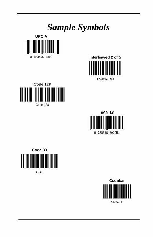
Sample SymbolsUPC A
0 123456 7890 Interleaved 2 of 5
Code 128
EAN 13
Code 39
Codabar
1234567890
Code 128
9 780330 290951
BC321
A13579B

Sample SymbolsPDF417
Postnet
Code 49
Data Matrix
QR Code
Car Registration
Zip Code
1234567890
Test Symbol
Numbers
OCR-A Sample
55836540
OCR-B Sample
55836540
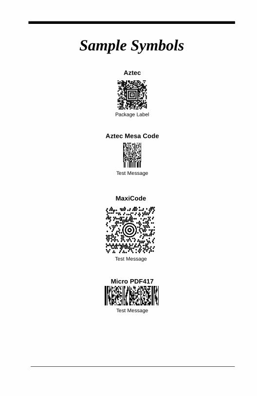
Sample Symbols
Aztec
Aztec Mesa Code
MaxiCode
Micro PDF417
Package Label
Test Message
Test Message
Test Message

Programming Chart
0
2
6
1
7
54
3

Programming Chart
8
A
E
9
F
DC
B
Save Discard
E

Programming Chart (OCR)
a
ed
l
Save Discard
c
t

4619 Jordan RoadP.O. Box 187
Skaneateles Falls, New York 13153-018744/4700/UG Rev H