danubia: an integrative simulation system for … an integrative simulation system for global ... we...
TRANSCRIPT
DANUBIA: An Integrative Simulation System
for Global Change Research in the
Upper Danube Basin ∗
Michael Barth, Rolf Hennicker, Andreas Kraus, Matthias Ludwig
Institute for Informatics, Ludwig-Maximilians-Universitat MunchenOettingenstr. 67, D-80538 Munich, Germany
Abstract
We describe the concepts and design principles of the integrative sim-ulation system DANUBIA which supports the analysis of water-relatedglobal change scenarios in the Upper Danube Basin. DANUBIA providesan internet-based platform integrating the distributed simulation mod-els of all socio-ecological and natural science disciplines taking part inthe GLOWA-Danube project which is part of the German Programme onGlobal Change in the Hydrological Cycle. As a result of coupled simu-lations transdisciplinary effects of mutually dependent processes can beanalysed and evaluated. Actually thirteen simulation models of meteorol-ogy, landsurface, water research and social sciences are integrated in theDANUBIA-system.
The development of DANUBIA is based on object-oriented softwareengineering and Web engineering methods ([2, 8, 9]) and on the UnifiedModeling Language UML [1] which is used by all partners as a commongraphical notation for modelling the integrative aspects of the system.
We describe how the mutually exchanged information between com-ponents is modelled and documented by interfaces, we discuss spatialaspects and show how simulation areas are represented and we considertemporal aspects and describe the coordination of local models by a globaltime controller which constitutes the heart of any integrative DANUBIAsimulation. Finally, we provide an overview of the architecture of theDANUBIA implementation which has been realised in Java. The imple-mentation integrates a wrapper framework that hides the technical detailsof network communications.
Keywords: integrated simulation of water-related processes, distributed simu-lation system, object-oriented development, unified modelling language UML
∗This work is part of the GLOWA-Danube project 07GWK04 sponsored by the GermanFederal Ministry of Education and Research.
1

1 Introduction
The GLOWA-Danube project is part of the GLOWA initiative which has beenestablished by the German Ministry of Education and Research to address thevarious consequences of Global Change on regional water resources in a vari-ety of catchments with different natural and cultural characteristics (cf. [7]).Within the GLOWA programme the GLOWA-Danube project is dealing withthe Upper Danube Basin covering an area of almost 80.000 square kilometres.Many water-related conflicts arise in this area concerning, for instance, waterquality and water utilisation, environmental protection, flood risks, tourism andvulnerability of mountain environments due to climatic change. With GLOWA-Danube a first attempt is made to model a large Alpine watershed with all itsspecific challenges such as climate, lateral flows, glacier and snow as well asdifferent administrative systems under combined natural and social science as-pects. The Alps and their foreland show large gradients in climate, vegetationand water supply within a comparably small area which, together with gooddata coverage in both natural and social sciences, makes the Upper DanubeBasin an excellent prototype for integrative research. Figure 1 illustrates themajor issues of integrated Global Change research in alpine watersheds. An ex-position of these issues focusing on the integrative aspects of GLOWA-Danubecan be found in [10].
VegetationPlant Ecology,Agriculture- andForst Economy
GlaciologySnow- andIce Modelling
Remote SensingIntegrative EnvironmentalMonitoring, Validiation
TourismTouristic Use andWater Conflicts
MeteorologyMesoscale Modelling,Land-AtmosphereInteraction, Rainfall
Human DimensionWater Use, Market,Water Conflicts,Regulations
HydrologyEvapotranspiration,Lateral Flow,Percolation, Discharge
Water ResourcesGround Water,Water Supply Water Resources
Surface Water, WaterQuality, Storage Operation
Figure 1: Issues of integrated Global Change research in alpine watersheds
2

More than a dozen of research groups covering the disciplines of meteorology,hydrology, remote sensing, ground- and surface water management, glaciology,plant ecology, environmental psychology, environmental and agricultural econ-omy, tourism research and computer science have joined GLOWA-Danube toinvestigate integrative approaches and tools to support decision making for asustainable environmental management.
1.1 Objectives and Basic Structure of the DANUBIA-System
In this paper we focus on the design and construction of the DANUBIA-systemwhich integrates simulation models of each of the single disciplines participatingin GLOWA-Danube. The objectives of DANUBIA are
• to perform and monitor integrative simulations,
• to analyse transdisciplinary effects of mutually dependent processes and
• to support decision making on the basis of water-related scenarios.
An important characteristic of DANUBIA is the dynamic coupling of the singlesimulation models which exchange information on runtime during an integra-tive simulation. Thus it is possible to model mutually dependent processes asillustrated for instance in Figure 2.To group related simulation models together five major components have beenidentified which contain models for the simulation of processes in the atmo-sphere, on the landsurface, in the groundwater and river and social processesconcerning the behaviour of actors like tourists, farmers, water suppliers, house-holds and economists. Figure 3 shows the basic structure of the DANUBIA-system.Each component is connected to the central DANUBIA database. This ensuresthat all models use the same GIS-data for terrain, land use and statistics. In-tegrative simulations are started and controlled by the DANUBIA managingcomponent. DANUBIA is designed as an internet-based platform where userscan start and access simulations and their results via a Web-browser. Figure 4shows a visualisation of selected outputs of an integrative simulation.
1.2 System Development Principles
The development of DANUBIA is guided by advanced software engineeringmethods based on the principles of abstraction, separation of concerns, sys-tem modelling and object orientation. Abstraction is important to focus onthe essential properties of the system and to abstract from unnecessary details.Together with a clear separation of concerns (for instance, separating spatialaspects from temporal aspects) the system complexity can be managed. Thedifferent views on the system are described by so-called system models which
3

RADIATION
BIOLOGICAL
SOIL
Capillary Rise
Root Water Uptake
Transpiration
EvaporationInfiltration
Subsurface Runoff
Recharge
Interception
Runoff
Radiation Balance
Sensible / LatentHeat Flux
Soil Heat Flux
N–Leaching / N in Groundwater
Root Nitrogen Uptake
N-Transformation
Water & Energy Matter
SNOW
N-Deposition /N-Fertilization
Photosynthesis
Respiration
Allocation &Growth
Snow – Ice - melt
Soil Heat Flux
Figure 2: Mutually dependent landsurface processes
DANUBIAManager
DANUBIADatabase
atmosphere landsurface rivernetwork groundwater actors
Web−Browser
Figure 3: Basic structure of the DANUBIA-system
4

Figure 4: Web interface of DANUBIA
5

are presented in a diagrammatic form. In the GLOWA-Danube project the Uni-fied Modeling Language UML [1] (which is the de-facto standard for modellingobject-oriented systems) is used by all members as a common graphical notationto provide an abstract description of DANUBIA and to define the interfaces be-tween the disciplines. The discussions during the set-up of the diagrams showedthat a clear assignment of the responsibilities of each group was successfullysupported by using UML as a common modelling language.The object-oriented approach is used in all phases of the development processranging from abstract analysis models to object-oriented implementations. Itis particularly appropriate for DANUBIA because real world objects occurringin the application domain of GLOWA-Danube (like plants, glaciers or variouskinds of actors) can be easily mapped to corresponding software objects. Fromthe static point of view the fundamental software units of an object-orientedsystem are classes which can be connected by associations. Each class describesthe characteristic properties (attributes and operations) owned by the objects ofa class. Objects themselves have a state which is determined by the actual valuesof the attributes at a certain point in time. For instance, Figure 5 shows twoclasses Tree and Forest with an association in between. The multiplicity 0..1attached to one association end indicates that any tree belongs to at most oneforest and the multiplicity * attached to the other association end says that anyforest consists of arbitrary many trees. There are two attributes height and agewhich are owned by any tree and one operation grow which can be performedby a tree. A key principle of object orientation is the inheritance concept whichallows to specialise classes into subclasses. The objects of a subclass possessall properties of the parent class together with additional attributes and/oroperations defined in the subclass. Figure 5 shows a subclass Oak of Tree withthe additional attribute leafArea. In UML the inheritance relation is expressedby an arrow with a solid triangular arrowhead pointing from the subclass to thesuperclass. In the given example Tree is an abstract superclass and grow isan abstract operation which is realised in the subclass Oak. Names of abstractclasses and operations are written in italics.
grow()
Oak
Tree
Forestheight:Realage:Realgrow()
leaveArea:Real
* 0..1
Figure 5: UML class diagram
The dynamic behaviour of an object-oriented system is determined by the mes-sages exchanged between objects during the execution of the system. When a
6

message is received the object reacts by performing an operation which pos-sibly changes the state of the object. For instance, Figure 6 shows a simplecommunication where a forest object sends the message grow to a tree ob-ject. In UML communications between objects can be represented by sequencediagrams which show the interaction of objects in their temporal order. Theboxes represent objects, the dashed vertical lines indicate lifelines of objects andthe horizontal arrows represent messages. The receiver of a message reacts byexecuting an activity shown by a tall thin rectangle.
:Forest :Tree
grow()
Figure 6: UML sequence diagram
1.3 Key Concepts of DANUBIA
As a consequence of the system’s requirements four crucial concepts concerningthe following issues were investigated and realised in DANUBIA:
• The identification of interfaces for exchanging information and the struc-ture of components.
• The treatment of space and simulation areas.
• The treatment of time and the coordination of simulation models.
• The global system management and network communication.
The definition of interfaces and the hierarchical structure of components is de-tailed in Section 2. It refines the basic architecture shown in Figure 3 above.The DANUBIA space concept is based on the notion of a proxel object (cf. [12])which represents a “geographical atom“ having a state and the ability to performlocal processes. A simulation area is composed by a set of proxels and com-putations on simulation areas are performed proxelwise. The object orientedinheritance concept allows to specialise the general proxel class (which containsbasic proxel information relevant for all models, like geographical coordinatesand elevation) to various subclasses defining discipline dependent attributes andprocesses. The space concept is described more precisely in Section 3.Any simulation executed with DANUBIA models water-related processes overa specific period of time (days, months or years). For integrative simulations a
7

global time controller is necessary which coordinates the single models to workproperly together. The fundamental task of the time controller is to adminis-trate the overall time period for which an integrative simulation holds and tocontrol the order in which the single models are repeatedly stimulated to per-form their next computation step. In particular, the time controller solves thefollowing major issues:
• Each simulation model has an individual time rate (model time) in whichcomputations are periodically executed (ranging from minutes, like in me-teorology, to months, like in social sciences).
• Values that are accessed through interfaces must be in a consistent stateand must be valid with respect to the global simulation time.
A description of the DANUBIA time concept is given in Section 4.Actually DANUBIA is installed on a computer cluster with a network of 52nodes where the different simulation models reside. The implementation lan-guage is Java and the network communication is realised by Java’s RMI technol-ogy [11]. In the initialisation phase the global system manager establishes theconnections between the participating simulation models which then can worktogether coordinated by the time controller. For each single model the networkcommunication is hidden by a wrapper which simulates each remote interfaceby a corresponding proxy that resides on the client side. The global systemmanagement and the wrapper concept are described in Section 5.
1.4 Related Approaches
Competition and interaction of numerous water-related stakeholders puts in-creasing pressure on the natural environment and ecology. The EU WaterFramework Directive (WFD, [5]) stresses the importance of decision supportsystems as a tool in river basin management for sustainable development. Manyexamples of decision support systems can be found in the literature and manyprojects in this regard have been carried out in the EU-FP4 Environment andClimate programme as well as in the EU-FP5 research activity Energy, Envi-ronment and Sustainable Development (EESD, [6]). In the framework of theEESD programme, the project MULINO has been established to provide anoperational decision support system for the multi-sectoral simulation of humanactivities, serving for the assessment and management of sustainable use ofwater resources. A GIS-based integration methodology of socio-economic andenvironmental modelling techniques is designed to support water managementfor various decisional cases in representative European catchment areas. In theproject MODULUS [3] a generic spatial decision support system has been devel-oped for integrated environmental policy making at the regional level operatingat very different temporal and geographical scales. In this system individualmodels were integrated to represent the physical, economic and social aspectsof land degradation and desertification in Northern Mediterranean watersheds.
8

Other approaches are making extensive use of modern information and commu-nication technologies such as the Finnish Web-HIPRE system [4]. The Europeanfunded project DAUFIN is dedicated to improve the efficiency of water resourcesmanagement.As far as we can see these systems basically run single simulation models andintegrate the final results which is different from the DANUBIA approach wheremodels are coupled and information are dynamically exchanged during runtime.Moreover, to our knowledge, GLOWA-Danube is the first project in this areawhich successfully applies a common modelling language used by all participat-ing research groups.
2 Components and Interfaces
One of the major tasks of the system analysis was to clarify the mutual depen-dencies between the participating disciplines by identifying the kinds of infor-mation to be exchanged between the different simulation models. Each singlemodel plays two roles, acting as a supplier and also as a user of information.After a careful (pairwise) analysis of requested and supplied information a set ofinterfaces between GLOWA-Danube models has been identified and graphicallydocumented with the Unified Modeling Language (UML). Figure 7 shows thegeneral form of interface diagrams in the case of three participating models A, Band C which exchange information through the interfaces AToB, AToC, BToA andCToB. Circles in the upper right corner indicate interfaces and operations of theform getX():Datatype describe services that an interface offers.The model which implements an interface (connected to the interface by adashed line with a solid triangular arrowhead) is responsible for providing theinterface information which can be used by the client model. One such interfacealways plays two roles: In Figure 7, for example, the interface AToB acts as anexport interface for A and as an import interface for B.
getInfoB():InfoBType
BToA
getInfoA1():InfoA1TypeAToB
getInfoA2():InfoA2Type
AToCC
CToB
getInfoC():InfoCType
BA
Figure 7: Interfaces between models
In GLOWA-Danube many different models are involved and diagrams as shownin Figure 7 soon become too complex. To overcome this problem five major com-ponents have been identified (atmosphere, landsurface, rivernetwork, groundwa-ter and actors, cf. Section 1, Figure 3) which group together logically related
9

models. Each component is equipped with a component controller which han-dles the exchange of information with other components and between modelsof the same component. Each single component contains itself a local networkconsisting of the models and interfaces inside the component. For instance, theinner structure of the landsurface component contains simulation models forplant ecology, radiation balance, soil, surface and snow&glaciers, the actor com-ponent contains socio-economic models for households, economy, demography,water supply, tourist and farming. The kind of decoupling described above isessential for building complex systems.Figure 8 shows parts of the inner structure of the major components landsurfaceand actor, described by a UML package diagram. For lack of space some modelsare omitted and some interfaces are represented by circles with the interfacename attached but without get-operations.Note that concrete datatypes are used for the return types of the get-operations,like e.g. ArableLandcoverCollection. A complete datatype hierarchy has beendeveloped which captures all datatypes used within the DANUBIA-system.
Farming
FarmingToActorContoller
Economy WaterSupply
actor
ActorControllerToFarming
EconomyToActorController WaterSupplyToActorControllerActorController
ActorToLandsurface
getArableCollection():ArableLandcoverCollection...
LandsurfaceToActor
...getSnowCover():Fraction
landsurface
LandsurfaceControllerToSoilLandsurfaceControllerToSnow
SnowToLandsurfaceController
LandsurfaceController
SoilToLandsurfaceController
BiologicalSnow
LandsurfaceControllerToBiological
getArableCollection():ArableLandcoverCollection...
Soil
BiologicalToLandsurfaceController
getBiomass():Biomass
getAgriculturalDrinkingWaterDemand():WaterFluxgetArableCollection():ArableLandcoverCollection...
getAgriculturalDrinkingWaterSupply():WaterFlux...
ActorControllerToWaterSupplyActorControllerToEconomy
...
Figure 8: Interfaces and hierarchical structure
10

3 Treatment of Simulation Space
An important aspect of (spatial) simulations is the treatment of the simulationspace. From a programmer’s point of view space is often only expressed implic-itly by using two dimensional arrays of data. In this section the concepts for thetreatment of space within DANUBIA are introduced starting from an abstractviewpoint.Simulation space is represented by a two dimensional net spanned by a coordi-nate system as depicted in Figure 9. Coordinates can be mapped to geographicalcoordinates which is done within the DANUBIA-system by using the Lambertprojection. Applying the paradigm of object-orientation the simulation spacedoes not only have structure, i.e. a net of pixels with attributes such as geograph-ical coordinates and elevation, but also behaviour which essentially consists ofthe processes that take place at the locations in the net. These objects are calledproxels (an acronym for process pixels). Applying the concept of inheritance,these proxels are specialised by the individual disciplines, such as for example asurface or a biological proxel.
3.1 Modelling of Simulation Areas
The simulation space is modelled by the class SiteMetaData (see Figure 10) thatcomprises a numeric identifier (sid attribute), a site name (name attribute), thenumber of columns and rows (nCols and nRows attributes), the parameters ofthe Lambert coordinate system (the xllcorner, yllcorner) and resolutionattributes. Simulations always take place in a particular area of a correspondingSiteMetaData object, e.g. the Ammer river region or the whole Upper DanubeBasin. This is expressed by the association between the class SiteMetaDataand the class AreaMetaData which additionally defines the upper left cornerrelative to the SiteMetaData and the number of columns and rows.Every proxel of the simulation space has a unique numeric identifier, the proxelid (short: pid) as illustrated in Figure 9. This identifier is globally valid and thusindependent of the chosen area. The SiteMetaData as well as the AreaMetaDataclasses (depicted in Figure 10) provide transformation operations to transformbetween proxel ids and rows and columns. The algorithm for deriving the proxelid from columns and rows of a SiteMetaData is implemented by the operationgetPID as follows
getPID(col , row) = col + row · nCols ,
whereas the reverse transformations are given by
getColByPID(pid) = pid mod nCols ,
getRowByPID(pid) = pid ÷ nCols .
The mod function calculates the integral modulo and the ÷ operator dividestwo integral numbers truncating the division result.
11

�na
me=
Dan
ube
Bas
in�
sid=1
�nC
ols=
425
�nR
ows=
430
�re
solu
tion=
1000
[m]
�xl
lcor
ner=
... [
m]
�yl
lcor
ner=
... [
m]
(Lam
bert
)
pid=
0pi
d=42
4
pid=
425
pid=
1823
26
pid=
1827
49(x
llcor
ner,y
llcor
ner)
Figure 9: Site description of the Upper Danube Basin
3.2 Design of the Proxel Hierarchy
For storing spatial objects the concept of a table is used, which means thatobjects can be stored and retrieved by supplying the proxel id. The abstractclass Table is used for storing spatial objects as can be seen in Figure 11. Theirinstances have a reference to an AreaMetaData object. Specialisations of thisclass are, on the one hand, the abstract class DataTable which is the base classfor spatial data and, on the other hand, the abstract class ProxelTable whichin turn is the base class for storing arbitrary Proxel objects. The proxels areaccessed via the getProxel and putProxel operations. The getPIDArray op-eration returns an array of all proxel ids of proxels that are inside the simulationcatchment by querying the DANUBIA database.Proxels have a state that is given by the values of a proxel’s attributes. Theyare organised in the proxel hierarchy by using the object-oriented inheritance
12

name : Stringaid : IntegernCols : IntegernRows : IntegerulCol : IntegerulRow : Integer...
getAreaColByPID( pid : Integer ) : Integer
...
AreaMetaData
name : Stringsid : IntegernCols : IntegernRows : Integerresolution : Integerxllcorner : Integeryllcorner : Integer
getColByPID( pid : Integer ) : Integer
......
...
SiteMetaData
getRowByPID( pid : Integer ) : IntegergetPID( c : Integer; r : Integer ) : Integer
getAreaRowByPID( pid : Integer ) : IntegergetPID( c : Integer; r : Integer ) : Integer
Figure 10: Site meta data and area meta data
concept. The abstract base class Proxel for all proxel classes describes the in-formation that is common to all proxels within DANUBIA such as geographicalcoordinates and elevation. As explained below a model’s compute operationis called to perform one computation step. It iterates over all proxels by call-ing the operation computeProxel of each proxel inside the simulation area tochange its state. This operation has to be implemented in concrete subclasses(as for example the BiologicalProxel class) by model specific computation al-gorithms. As depicted in Figure 12 the specialisations of the Proxel class builda proxel hierarchy that corresponds to the structure of the components shown inFigure 8. For instance LandsurfaceProxel is the common abstract superclassof all landsurface proxels. The leaf classes such as BiologicalProxel defineadditional attributes.
3.3 Integration of Components and Space
In Section 2 the component concept of DANUBIA was introduced. The spatialaspect has a strong influence on the component concept. On the one hand,the actual computation takes place in the proxels which are organised in proxeltables. On the other hand, spatial data organised in data tables is exchangedbetween components. In the example depicted in Figure 13 we focus on themodel Biological. The return types of the operations of import and exportinterfaces are modified to return now tables of data, i.e. spatial data. The im-ported tables like, for example, ArableLandcoverCollectionTable are associ-ated with the model. The same holds for the exported tables like BiomassTablewhich are updated after each computation step of a model. Of course themodel has an association to its corresponding proxel table, in our example theBiologicalProxelTable, which in turn is composed of BiologicalProxels.
3.4 Proxelwise Computation
In DANUBIA all computations of the simulation models are performed on theproxels. When the operation compute() is called for a model, it iterates via the
13

...
AreaMetaDataTable
...
putDataElement( pid : Integer; de : DataElement )...
getDataElement( pid : Integer ) : DataElement
DataTable...
getProxel( pid : Integer ) :ProxelputProxel( pid : Integer; p : Proxel )
getPIDArray() : Integer[]
ProxelTable
pid : Integerarea : Areaeasting : Lengthnorthing : Lengthelevation : Length...
...
Proxel
computeProxel()
*
1
Figure 11: Base classes for handling spatial data
proxel table over all relevant proxels and sends the message computeProxel()to each proxel. This process is depicted in the sequence diagram in Figure 14with respect to the sample component Biological.The message compute is asynchronous, i.e. the sender will continue and not waitfor a response, which is indicated by a half arrowhead. As we will see in Section4 this message is sent by the time controller. The message getBiological-Proxel(pid) is synchronous (indicated by a full arrowhead) and returns foreach call a proxel object bp.
3.5 Interface to the Database
Before an integrative simulation can be processed each component has to be ini-tialised properly with data from the database. First, a reference to the databaseis passed to the model. Then the model creates a corresponding proxel tablewhich in turn creates proxel objects for the whole simulation site. In a nextstep, the communication with the database starts and the basic geographicalproxel properties are retrieved and spread to the proxel attributes to initialisetheir state.
4 Time and Computation
In the preceding sections techniques how models can export their data andimport necessary data from other models were explained. During computation
14

LandsurfaceProxel
...snowCover : Fraction
computeProxel()...
SnowProxel
...biomass : Biomass
computeProxel()...
...sls : SoilLayerStack
computeProxel()...
SoilProxel
ActorProxel
Proxel
BiologicalProxel ...
Figure 12: Example for the proxel hierarchy
the value of any data may change. Consequently, a model can not export orimport data while it is computing. Thus the access to the operations thatchange the data of a model and the operations that export them have to bemutually excluded. The model spends most of the time on the computation ofnew data. If the set of data that can be exported is stored in a separate place(export table) and the computation is executed on an internal copy, the datafrom this export table can be exported during the computation. At the endof one computation step the export table has to be updated with the values ofthe internal copy. These two phases, computation and updating (later on calledwriting), are alternating in each step.Each computation step represents a specific time step of a simulation (e.g. 10 min-utes, one hour, one day, one month), in the following called model time. Ofcourse, the model time is different from the real computation time a modelneeds to compute new data. If several models are integrated to simulate acommon time period they must be properly coordinated.
4.1 The Model Time Concept
A time controller concept constitutes the heart of the DANUBIA system. Thefundamental task of the time controller is to administrate the overall time periodfor which an integrated simulation should hold and to control only the orderin which the single models are repeatedly stimulated to perform their nextcomputation step, to import data from other models or to update their exporttables.The time controller has to guarantee the consistency of the overall model timeperiod and some requirements like mutual exclusion of reading and writing ofdata. As shown in Figure 15, the time controller synchronises the computationof all models from a central position. The formerly stand-alone software modelsbecome integrated in one major control flow and their role changed to a timecontroller driven simulation model.Figure 16 shows a UML state diagram which describes the states and thestate transitions of any simulation model integrated in DANUBIA. The states
15

Biological
BiologicalProxelTable
getBiologicalProxel(pid:Integer):BiologicalProxel
AreaMetaData
...getArableCollection():ArableLandcoverCollectionTable
LandsurfaceControllerToBiological
BiologicalProxelbiomass:Biomass...
...computeProxel()
get(pid:Integer):Biomass
...put(pid:Integer, de:Biomass)
BiomassTable<<exported table>>
...
get(pid:Integer):ArableLandcoverCollectionput(pid:Integer, de:ArableLandcoverCollection)
ArableLandcoverCollectionTable<<imported table>>
compute()...
BiologicalToLandsurfaceController
getBiomass():BiomassTable
*
1
Figure 13: Example for integration of the components and space concept
processGetData, processCompute and processCommit represent activity stateswhere a simulation model is active. In the other states (waitForCompute,waitForCommit) the simulation model is waiting for messages from the timecontroller. The transitions between the states are annotated with messagesthe simulation model receives (e.g. compute()) or sends to the time controller(e.g. /timecontroller.validState()).At the beginning of a computation step the simulation model is waiting in theinitial waitForCompute state. As soon as the time controller ascertains that amodel can start its next computation step it sends the compute() message tothe model. The model receiving this message changes to the processGetDatastate. In this activity state the model reads data from the export interfacesof other models. The time controller will only send this message to a modelif it is guaranteed that all data is valid and stable for the whole duration ofthis activity. The processGetData state designates one of the critical sections.When the model has read all data it notifies the time controller of leaving thecritical section and entering the processCompute state by sending the messagecomputationStarted() to the time controller.During the next activity (processCompute) the simulation model computes allnew values on the internal copy of its data. After the computation has finishedthe model sends the computationFinished() message to the time controllerand enters the stable waitForCommit state. The model will remain in this stateuntil it receives the commit() message from the time controller.When the time controller ascertains that the model may write the changed val-
16

:Biological :BiologicalProxelTable bp:BiologicalProxel
compute()
computeProxel()
bp=getBiologicalProxel(pid)
Figure 14: Sequence diagram for proxelwise computation
LandsurfaceController
compute()commit()...
timecontroller
Timecontroller
Snow
compute()commit()...
compute()commit()...
Soil
landsurface
Biological
computationStarted()
validState()computationFinished()
...
Figure 15: The time controller driven architecture
ues of its internal copy to its export table, the time controller sends commit() tothe model. Then the model enters the processCommit state. During this activ-ity the model updates its export tables. The processCommit state designatesthe second critical section. The time controller will only send the commit()message to a model if it is guaranteed that no other model will read data fromthe tables at the same time. After the model has finished to write its data to
17

waitForCompute
processGetDataprocessCommit
waitForCommit processCompute
/timecontroller.computationFinished()
compute()
commit() /timecontroller.computationStarted()
/timecontroller.validState()
Figure 16: The states of a simulation model
the export tables it notifies the time controller of leaving the critical section bysending the validState() message. Then it enters the stable waitForComputestate again waiting for the next compute() message to perform its next compu-tation step.
4.2 Time Controller Implementation
The development of the time controller implementation was performed in anextra software development cycle consisting of analysis, design, implementa-tion and test. The Java source code counts over 5600 lines of (uncommented)code. The distribution of the simulation models is realised using Java’s Re-mote Method Invocation technology (RMI). Only some exemplary details of theimplementation model can be described here.
TCModelAccess
commit(ta:TCTransaction)compute(ta:TCTransaction)
TCConfirmation
TCModelRegistrationregister(m:TCModelAccess, t:TCDate, meta:TCModelMetadata):TCConfirmation
validState(ta:TCTransaction)computationFinished(ta:TCTransaction)computationStarted(ta:TCTransaction)
Figure 17: Interfaces describing the protocol
The responsibilities of the simulation models and of the time controller aregrouped into interfaces. Figure 17 shows a UML class diagram containingthe TCModelAccess interface of the simulation model and the correspondingTCConfirmation interface of the time controller. The messages annotated atthe transitions of the state diagram of Figure 16 correspond to the operationnames.The TCModelRegistration interface is also implemented by the time controllerto allow the initial registration of all simulation models at the very begin-
18

ning of a simulation run. After the execution of the register operation theTCModelAccess interface is registered at the time controller and the operationreturns the TCConfirmation interface to the simulation model. The additionalparameters contain, among others, information about the model time and therelative duration of a time step.
State Design Pattern
ModelClientStateA
TCModelAccess
MessageReceiver
TCModelRegistration
TCConfirmation
Context
State ConcreteState
myPreviousState myActualState
ReceiverState
myContext* *
1 1
Figure 18: Usage of design patterns (State Pattern)
The states of the simulation model shown in Figure 16 have been directly im-ported into the implementation model using the so-called State Design Pattern.In the class diagram shown in Figure 18 the MessageReceiver class implementsthe time controller interfaces and manages its ReceiverState. The exemplaryModelClientStateA is replaced by a concrete implementation of a class repre-senting one of the states shown in Figure 16.The time controller implementation showed excellent performance right fromthe start and could easily be integrated in all models because of its small set ofinterfaces encapsulating all protocols and communication tasks.
5 DANUBIA Management Components andTechnical Realisation
This section describes the management and technical realisation of DANUBIAas a distributed system of coupled environmental simulation models.First we consider the components that are necessary to manage a DANUBIAsystem run and how they are distributed on different computers. Then weaddress the intrasystem processes controlled by the managing components fromstarting the entire system to the beginning of a distributed simulation. Finally,we describe the concept of the so-called network wrappers which facilitate andcontrol data exchange between the different models.
19
5.1 Static Structure
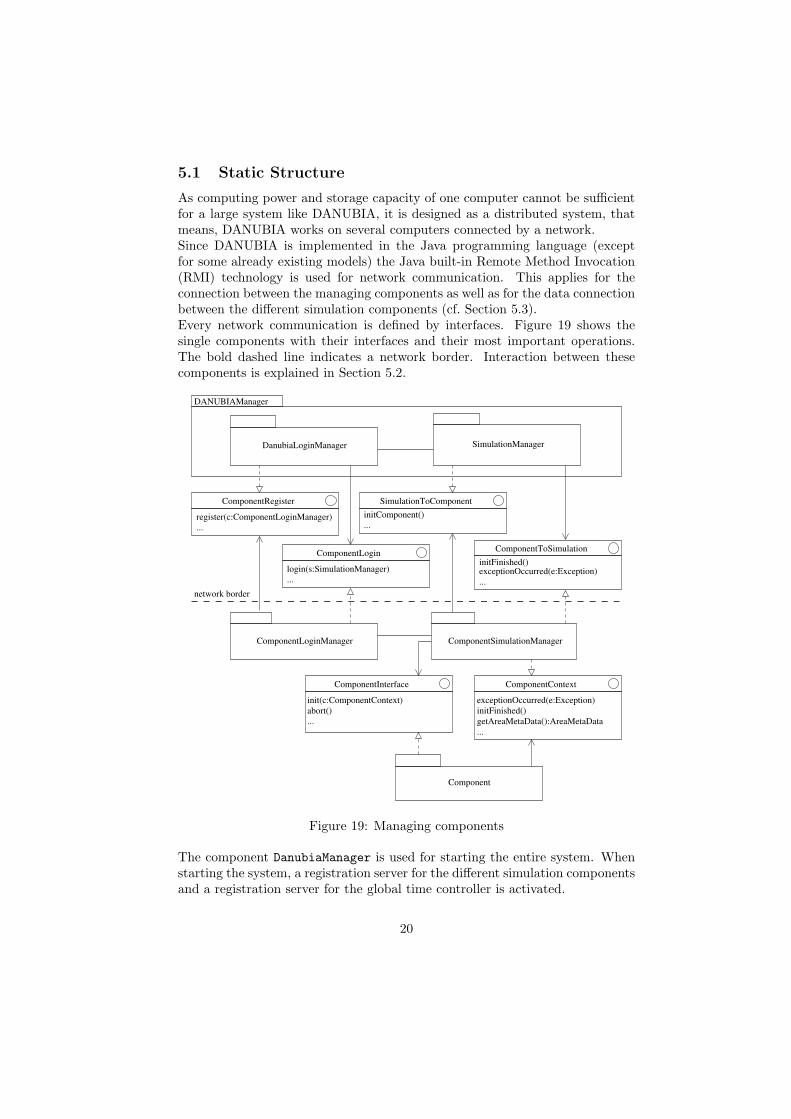
As computing power and storage capacity of one computer cannot be sufficientfor a large system like DANUBIA, it is designed as a distributed system, thatmeans, DANUBIA works on several computers connected by a network.Since DANUBIA is implemented in the Java programming language (exceptfor some already existing models) the Java built-in Remote Method Invocation(RMI) technology is used for network communication. This applies for theconnection between the managing components as well as for the data connectionbetween the different simulation components (cf. Section 5.3).Every network communication is defined by interfaces. Figure 19 shows thesingle components with their interfaces and their most important operations.The bold dashed line indicates a network border. Interaction between thesecomponents is explained in Section 5.2.
DANUBIAManager
ComponentLogin
ComponentRegister
ComponentInterface ComponentContext
ComponentToSimulation
SimulationToComponent
DanubiaLoginManager SimulationManager
Component
ComponentLoginManager ComponentSimulationManager
login(s:SimulationManager)...
network border
register(c:ComponentLoginManager)...
abort()init(c:ComponentContext)
initFinished()exceptionOccurred(e:Exception)...
exceptionOccurred(e:Exception)initFinished()getAreaMetaData():AreaMetaData...
...initComponent()
...
Figure 19: Managing components
The component DanubiaManager is used for starting the entire system. Whenstarting the system, a registration server for the different simulation componentsand a registration server for the global time controller is activated.
20

After activation of the registration server a component administrator can starthis component by activating the ComponentLoginManager. This componentfirst registers the simulation component to the DanubiaManager and then waitsfor requests to start a simulation.The SimulationManager component is responsible for controlling a runningsimulation. All relevant information about a simulation like e.g. simulationtime and area, simulation models involved, etc. is stored here. It is also re-sponsible for the correct assignment of the distributed import interfaces to theircorresponding export interfaces.Finally, the ComponentSimulationManager provides for local simulation controlon the simulation component’s host computer. The main tasks of this compo-nent are to activate the model initialisation, to connect the model to the globaltime controller and to notify the global SimulationManager about errors andexceptional situations within the model.The simulation component itself is connected to the SimulationComponent-Manager by the interfaces ComponentContext and ComponentInterface.
5.2 Dynamic Structure
In the following we describe the interaction of the DANUBIA components fromthe start of the system to the start of a distributed simulation. The course of asimulation has already been elaborated in Section 4.Starting the entire system is done by activating the global DanubiaLogin-Manager as mentioned above. After that, the component administrators canstart the ComponentLoginManager of their components which registers the com-ponent to the DanubiaLoginManager immediately. These processes are de-scribed by the sequence diagram in Figure 20.
ComponentAdministrator
:DanubiaLoginManager
:ComponentLoginManagerDANUBIAAdministrator
register(self)
new()
new()
Figure 20: Start of the DANUBIA system
More interesting, however, is the start of a distributed simulation. A DANU-BIA user accesses the SimulationManager (SM) which in turn instructs theDanubiaLoginManager (DLM) to notify the ComponentLoginManager (CLM) ofevery component involved. The ComponentLoginManager then (asynchronously)creates a new ComponentSimulationManager (CSM) object and returns it to
21
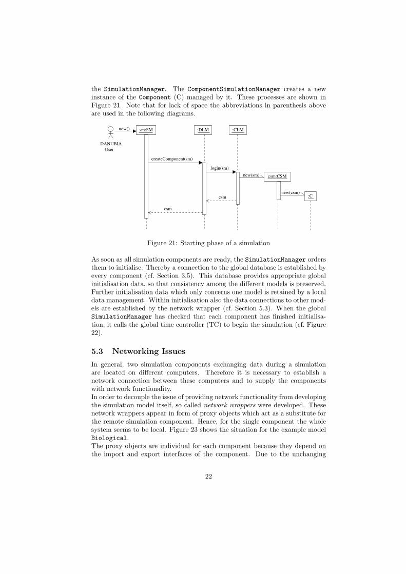
the SimulationManager. The ComponentSimulationManager creates a newinstance of the Component (C) managed by it. These processes are shown inFigure 21. Note that for lack of space the abbreviations in parenthesis aboveare used in the following diagrams.
sm:SM :DLM
csm:CSM
:CLM
DANUBIAUser
new()
csm
createComponent(sm)
csm
login(sm)new(sm)
new(csm):C
Figure 21: Starting phase of a simulation
As soon as all simulation components are ready, the SimulationManager ordersthem to initialise. Thereby a connection to the global database is established byevery component (cf. Section 3.5). This database provides appropriate globalinitialisation data, so that consistency among the different models is preserved.Further initialisation data which only concerns one model is retained by a localdata management. Within initialisation also the data connections to other mod-els are established by the network wrapper (cf. Section 5.3). When the globalSimulationManager has checked that each component has finished initialisa-tion, it calls the global time controller (TC) to begin the simulation (cf. Figure22).
5.3 Networking Issues
In general, two simulation components exchanging data during a simulationare located on different computers. Therefore it is necessary to establish anetwork connection between these computers and to supply the componentswith network functionality.In order to decouple the issue of providing network functionality from developingthe simulation model itself, so called network wrappers were developed. Thesenetwork wrappers appear in form of proxy objects which act as a substitute forthe remote simulation component. Hence, for the single component the wholesystem seems to be local. Figure 23 shows the situation for the example modelBiological.The proxy objects are individual for each component because they depend onthe import and export interfaces of the component. Due to the unchanging
22

initFinished()
sm:SM:TC csm:CSM :C
initComponent(sm)
init(csm)
initFinished()
beginSimulation()
check()
Figure 22: Initialisation of the components
structure of these interfaces the proxies can be generated automatically.The network wrapper is connected to the ComponentSimulationManager. Overthis channel it can forward networking errors to the global SimulationManager.Moreover, the wrapper implements strategies to recover lost network connec-tions and strategies to optimise data flow over the network by data caching.
6 Concluding Remarks
The experiences with running DANUBIA simulations have provided a proofof concept for the integrative design and coordination principles. The actualperformance of the system is measured with 40 seconds computation time forone hour model time. This is quite reasonable but will still be improved by apre-compiler that transforms the object-oriented representations of the variousdata types into low-level type representations.A major issue concerns the reliability of the outputs of integrated simulations.This requires, on the one hand, local tests for single simulation models and theirinterfaces and, on the other hand, a strategy for validating the output of coupledsimulations. For the former task, a local test environment has been developedwhich provides dummy implementations for all the needed interfaces of a singletest model which can simply be plugged in and tested on a local computer as ifit would run within the whole DANUBIA network. For the validation of coupledsimulations an appropriate approach will be investigated, based on sensitivityanalysis techniques, in the second phase of the GLOWA-Danube project from2004 to 2006.The ultimate goal of DANUBIA is to provide an integrated decision supportsystem that will be able to simulate water-related issues under ecological and
23

Biological
LandsurfaceControllerToBiologicalClient<<proxy>>
...getArableCollection():ArableLandcoverCollectionTable
<<proxy>>
getBiomass():BiomassTable
<<proxy>>LandsurfaceControllerToBiologicalServer BiologicalToLandsurfaceControllerClient
...getArableCollection():ArableLandcoverCollectionTable
BiologicalToLandsurfaceController
...getArableCollection():ArableLandcoverCollectionTable
LandsurfaceControllerToBiological
...getBiomass():BiomassTable
LandsurfaceController
BiologicalToLandsurfaceController
...getArableCollection():ArableLandcoverCollectionTable
LandsurfaceControllerToBiological
...getBiomass():BiomassTable
biological.wrapper
landsurfacecontroller.wrapper
BiologicalToLandsurfaceControllerServer<<proxy>>
getBiomass():BiomassTable
network border
Figure 23: Network wrapper for the simulation components
economical aspects, to analyse global change scenarios and to support a sus-tainable environmental management of water in the Upper Danube Basin. Animportant step towards this goal has been done with the development of theintegrated simulation system realised by the current version of DANUBIA in thefirst three years of GLOWA-Danube. In the second phase of the project the sys-tem will be enhanced by components for decision support which, in particular,include components for the construction, evaluation and administration of com-plex scenarios involving external and internal decision making by stakeholdersand by internal actor simulations.
References
[1] Booch, G., Rumbaugh, J., Jacobson, I.: The Unified Modeling LanguageUser Guide. Addison-Wesley, Object Technology Series, 1999.
24

[2] Bruegge, B., Dutoit, A. H.: Object-oriented Software Engineering: Con-quering Complex and Changing Systems, Prentice-Hall, 2000.
[3] Engelen G. (ed.): MODULUS: A Spatial Modelling Tool for Integrated En-vironmental Decision-Making, Final Report, Contract ENV4-CT97-0685,Directorate General XII, Environment IV Framework, Brussels, Belgium,2000.
[4] http://www.hipre.hut.fi (last visited 2003/08/12)
[5] http://europa.eu.int/comm/environment/water/water-framework/index_en.html (last visited 2003/08/12)
[6] http://www.cordis.lu/eesd (last visited 2003/08/12)
[7] GSF - Forschungszentrum fur Umwelt und Gesundheit GmbH (ed.): Ger-man Programme on Global Change in the Hydrological Cycle, Status Re-port 2002, produced on behalf of the BMBF (German Federal Ministry forEducation and Research).
[8] Hennicker, R., Koch, N.: Systematic Design of Web Applications withUML. In: K. Siau, T. Halpin (eds.): Unified Modeling Language: SystemsAnalysis, Design and Development Issues, Hershey, PA (USA), London(UK): Idea Group Publishing, 2001.
[9] Kraus, A., Koch, N.: Generation of Web Applications from UML ModelsUsing an XML Publishing Framework. Conf. Proc. Integrated Design andProcess Technology, 2002.
[10] Ludwig R., Mauser W., Niemeyer S., Colgan A., Stolz R., Escher-VetterH., Kuhn M., Reichstein M., Tenhunen J., Kraus A., Ludwig M., Barth M.,Hennicker R.: Web-based Modeling of Water, Energy and Matter Fluxesto Support Decision Making in Mesoscale Catchments - the IntegrativePerspective of GLOWA-Danube. Physics and Chemistry of the Earth, toappear.
[11] Pitt, E., McNiff, K.: Java.rmi: The Remote Method Invocation Guide.Addison Wesley Professional. Reading, 2001.
[12] Tenhunen J. D., Kabat P. (Ed.): Integrating Hydrology, Ecosystem Dy-namics and Biogeochemistry in Complex Landscapes, John Wiley and Sons,Chichester, 1999.
25