daniel and matera have written the mashups - florian daniel · michael j. carey · stefano ceri...
TRANSCRIPT

1
Daniel · Matera
Data-Centric Systems and ApplicationsMichael J. Carey · Stefano Ceri Series Editors
Florian Daniel · Maristella Matera
Mashups Concepts, Models and Architectures
Data-Centric Systems and Applications
MashupsFlorian DanielMaristella Matera
Computer Science
DCSA
Mashups Concepts, Models
and Architectures
Mashups have emerged as an innovative soft ware trend that re-interprets existing Web building blocks and leverages the composition of individual components in novel, value-adding ways. Additional appeal also derives from their potential to turn non-programmers into developers.
Daniel and Matera have written the fi rst comprehensive reference work for mashups. Th ey systematically cover the main concepts and techniques underlying mashup de-sign and development, the synergies among the models involved at diff erent levels of abstraction, and the way models materialize into composition paradigms and archi-tectures of corresponding development tools. Th e book deliberately takes a balanced approach, combining a scientifi c perspective on the topic with an in-depth view on relevant technologies. To this end, the fi rst part of the book introduces the theoretical and technological foundations for designing and developing mashups, as well as for designing tools that can aid mashup development. Th e second part then focuses more specifi cally on various aspects of mashups. It discusses a set of core component tech-nologies, core approaches, and architectural patterns, with a particular emphasis on tool-aided mashup development exploiting modeldriven architectures. Development processes for mashups are also discussed, and special attention is paid to composition paradigms for the end-user development of mashups and quality issues.
Overall, the book is of interest to a wide range of readers. Students, lecturers, and researchers will fi nd a comprehensive overview of core concepts and technological foundations for mashup implementation and composition. Even without low-level coding details, practitioners like soft ware architects will fi nd guidance on key imple-mentation concepts, architectural patterns, and development tools and approaches. A related website provides additional teaching material which can be used either as part of a course or for self study.
This book is timely, provides a through scientific investigation and also has prac-tical relevance in the general area of composition and mashups. It is of particular interest to researchers and professionals wishing to learn about relevant concepts and techniques in service mashups, composition, and end-user programming. From the Preface by Boualem Benatallah, University of New South Wales, Sydney
9 7 8 3 6 4 2 5 5 0 4 8 5
ISBN 978-3-642-55048-5
Chapter 4 Model-Driven Software Development Figures

© Copyright 2014 by F. Daniel and M. Matera. Reproduction for classroom use and teaching allowed if source is properly cited.
4.2 Model-Driven Design 79
the context of model-based developed, i.e., conceptual modeling. We feel it isimportant to introduce the respective ideas and concepts, in order to clarifyits di↵erences and commonalities with MDSD and the respective terminology.
4.2.1 Conceptual modeling
Conceptual modeling has its roots in databases [27]. Before implementing adatabase, it is common practice today to first design one or more graphicalschemas (a synonym of “model” in the database community) of the databasestructure to be implemented. As illustrated in Figure 4.1, there are typicallythree di↵erent levels of abstraction in database design, in addition to thefinal code that implements the models in the chosen database managementsystem:
• Conceptual schema: This schema expresses the concepts, i.e., the entities,that the database will describe. The conceptual schema relates entities viarelationships, generalizations/specializations, and attributes. It is typicallyexpressed as Entity-Relationship (ER) diagram.
• Logical schema: This schema expresses the concepts of the conceptualmodel in terms of concepts that are compatible with the target databasetechnology. For instance, a relational database does not allow the use ofm:n relationships, a construct of the conceptual schema; such relationshipsmust therefore be translated into two 1:n relationships and a bridge table,in order for the model to be compatible with the relational data model.The logical schema is typically expressed as ER diagram with only a subsetof constructs (e.g., without generalizations or m:n relationships).
• Physical schema: This schema eventually expresses the database struc-ture in terms of the specific database technology and system chosen. Forinstance, the physical schema tells how to actually store data into files,how to index them, and similar. The physical model can, for example, beexpressed by drawing concrete tables, keys, and similar.
Conceptual schema
Physical schema
Code
Logical schema
Manual transformation
Manual transformation
Manual transformation
Platform-independent
Platform-dependent
Computation-independent
Fig. 4.1 The di↵erent schemas in the conceptual modeling stack for database design.
The conceptual schema is typically completely independent of any technol-ogy or platform. The logical level is technology-dependent (e.g., relational vs.

© Copyright 2014 by F. Daniel and M. Matera. Reproduction for classroom use and teaching allowed if source is properly cited.
4.2 Model-Driven Design 81
• XMI : All MOF-compliant models can be serialized and stored in the XMLMetadata Interchange (XMI) format [216], an XML mapping for the MOF.XMI enables interoperability among MDA tools like editors and code gen-erators.
• Models at di↵erent levels of abstraction: Similarly to the conceptual mod-eling approach, also MDA is based on three/four core models (see Figure4.2) [195], which in the case of MDA are all MOF-based and typicallyspecified via dedicated UML profiles:
– Computation-independent model (CIM): This model captures the do-main or business knowledge to be managed by the application underdevelopment, typically in the form of a UML class diagram (similar inexpressive power to the ER diagram of a conceptual schema). It rep-resents the static knowledge about the domain in a technology- andcomputation-independent fashion. The CIM is optional in MDSD.
– Platform-independent model (PIM): This model describes the applica-tion in terms of architectural styles, software components, relationships,and similar. It describes a solution in a technology-independent butcomputation-specific way, so that it is still portable among di↵erentplatforms with similar architectural and computing assumptions.
– Platform description model (PDM): This model describes the detailsof the target platform that enables the implementation of the modeledapplication. This model may come in a variety of di↵erent forms (fromformal models to informal documentation and manuals); the final visionis to describe also the PDM in a MOF-compliant fashion.
– Platform-specific model (PSM): Given a PDM, it is possible to map thePIM into a PSM, i.e., a model that expresses the PIM in terms of theconcrete platform chosen for the implementation of the application. Thelevel of abstraction of the PSM is not standardized and may vary fromconcrete implementations that can already be executed to lower-levelPIMs that need further transformation.
• Multi-stage transformations and action languages: MDA fosters the useof subsequent model-to-model transformations (e.g., from PIM to PSM),model-to-code transformations, model markings to guide the transforma-tion process, and action languages that are similar to model-based pro-
Computation-independent model (CIM)
Platform-specific model (PSM)
Code
Platform-independent model (PIM)
Automatic transformation
Automatic transformation
Automatic transformation
Platform description model (PDM)
based on
Fig. 4.2 Models and transformations in the Model-Driven Architecture (MDA) [195].

© Copyright 2014 by F. Daniel and M. Matera. Reproduction for classroom use and teaching allowed if source is properly cited.
4.2 Model-Driven Design 83
Architecture-centric model
Code
Automatic transformationCode generation
templatesuses
Fig. 4.3 The ingredients of architecture-centric model-driven software development(AC-MDSD) according to Stahl and Volter [256].
UML profile specifically tailored to the needs of the particular family of ap-plications to be supported. The necessary model-to-code transformation isachieved via suitable code generation templates able to generate the infras-tructure code of the generative software architecture. The architecture-centricmodel is very focused on the infrastructural aspects of the application to bedeveloped and does not provide means for the modeling and automatic gener-ation of custom, application-specific application code. Custom functionalitymust be implemented manually by the developer and can typically be pluggedin in the form of instances of specific architectural components, e.g., a webservice or Java Bean.
This strong focus on infrastructural elements and the treatment of cus-tom application logic as black boxes emphasizes the suitability of AC-MDSDfor the development of entire software families, such as EJB- or CORBA-based client-server applications and web applications, rather than individualproducts.
A very good example of AC-MDSD in practice is WebRatio (http://www.webratio.com/), an Eclipse-based engineering platform and mod-eling tool for the model-driven development of Java-based, data-intensiveweb applications. WebRatio is based on EJBs and an extended Model-View-Controller (MVC) architecture, which allows the modular management oftypical web application concerns. The modeling tool is based on the WebModeling Language (WebML) [69], a platform-independent modeling lan-guage featuring constructs such as pages, hyperlinks, content units (render-ing content inside a web page), operation units (processing and manipulatingdata), web service units (invoking remote web services), and similar. All unitshave an optimized reference implementation (in the form of EJBs), which onlyneeds to be instantiated at runtime for each individual web application. Thisinstantiation is achieved by generating (among other artifacts) suitable XMLdescriptors for each instance of unit in the WebML model, which can beread and interpreted by the respective reference implementation at runtimein order to provide the functionality expressed in the WebML model. Theinitial versions of WebRatio featured an XSLT-based code generator, whilethe latest version of the tool natively implements the code generation logicin Java (according to the developers of WebRatio, for performance reasons).

© Copyright 2014 by F. Daniel and M. Matera. Reproduction for classroom use and teaching allowed if source is properly cited.
84 4 Model-Driven Software Development
4.3 Metamodeling
The centerpiece of MDSD are the models that are used to design applica-tions in a graphical manner. Metamodeling is the activity that is concernedwith the design of the modeling languages that actually enable the abstractdevelopment approach that characterizes MDSD. Good modeling languagescontain fundamental conceptual, domain, and technological knowledge re-garding the development of their target applications and represent the corevalue of MDSD. Without sensibly and purposefully designed modeling lan-guages, MDSD would not be useful. It is therefore of utmost importance thatdevelopers put the necessary e↵ort – and competence – into the design oftheir modeling languages, especially if we consider that modeling languagestypically do not change fast over time and are designed to support the devel-opment of multiple applications on top of a same platform infrastructure.
4.3.1 The metalevels
A model, e.g., a UML object diagram, describes the structure and nature ofinstances, e.g., runtime objects for a given instant of time during the exe-cution of an application. Similarly, a metamodel describes the structure andnature of model elements, i.e., model constructs. The prefix “meta” indicatesthat we are dealing with models about models. That is, the term is relative,i.e., referring to the model the metamodel is talking about, not absolute.
In Figure 4.4, we show the four metalevels introduced by the OMG, de-noted M0, M1, M2, and M3. The metalevel M0 corresponds to concrete run-time instances of an application; the metalevel M1 to the model of the appli-cation; the metalevel M2 to the model of the model (the metamodel), i.e., to
Meta-metamodel
Metamodel
Model
InstancesM0
M1
M2
M3
<<instance of>>describes metamodel
constructs
describes model
constructs
describes
instances
<<instance of>>
<<instance of>>
Fig. 4.4 The four metalevels proposed in OMG’s Meta Object Facility [215].

© Copyright 2014 by F. Daniel and M. Matera. Reproduction for classroom use and teaching allowed if source is properly cited.
4.3 Metamodeling 85
Meta-metamodel
Metamodel
Model
InstancesM0
M1
M2
M3
<<instance of>>
<<instance of>>
<<instance of>>
PIM 1 metamodel
PIM 2 metamodel
PSM 2 metamodel
PIM 1 PIM 2 PSM 2
<<instance of>> <<instance of>> <<instance of>>
transformation transformation
<<instance of>> <<instance of>> <<instance of>>
Fig. 4.5 Meta levels vs. abstraction levels. Abstraction levels express di↵erent ab-stractions of a same artifact (the application) at metalevel M1; metalevels expressdi↵erent artifacts (instances, model constructs, metamodel constructs).
the specification of the modeling language that can be used in the metalevelM1; and the metalevel M3 corresponds to the model of the metamodel, i.e.,to the language that can be used for the specification of metamodels in M2.The meta-metamodel in M3 is defined in terms of itself, a hierarchy thatcan be iterated ad infinitum, without however practical implications in thecontext of MDSD.
For instance, OMG’s MDA initiative proposes the use of UML at the met-alevel M1 (e.g., object diagrams), of UML and UML profiles at metalevel M2(e.g., class diagrams and UML extensions), and of the Meta Object Facility(MOF) [215] at the metalevel M3. For metamodels that are not compliantwith the MOF, the metalevel M3 can also be neglected, while the metamodelof the modeling language for M1 must be described formally, in order forMDSD to be able to leverage on it.
Before looking at some concrete examples of metamodeling, we would liketo clarify upfront the di↵erence between abstraction levels (CIM vs. PIM vs.PSM) and metalevels. The former are used to specify di↵erent views on asame artifact, in order to ease development and to allow the developer toincrementally focus on di↵erent aspects of the same software project. Thelatter are used to specify artifacts that are independent of each other, i.e.,instances, model constructs, and metamodel constructs. Although at firstglance also the latter might look like some form of “abstractions”, they arenot. A model is an instance of a metamodel; a PSM is a refinement of a PIM.We graphically illustrate this di↵erence in Figure 4.5.
© Copyright 2014 by F. Daniel and M. Matera. Reproduction for classroom use and teaching allowed if source is properly cited.
86 4 Model-Driven Software Development
4.3.2 Metamodels, MOF and UML profiles
For the concrete specification of a metamodel, there are multiple techniquesthat can be used, depending on the desired interoperability and the expectedimportance of the metamodel to be developed: generic metamodels, UMLinheritance, MOF-based metamodels, and UML profiles.
4.3.2.1 Generic metamodel
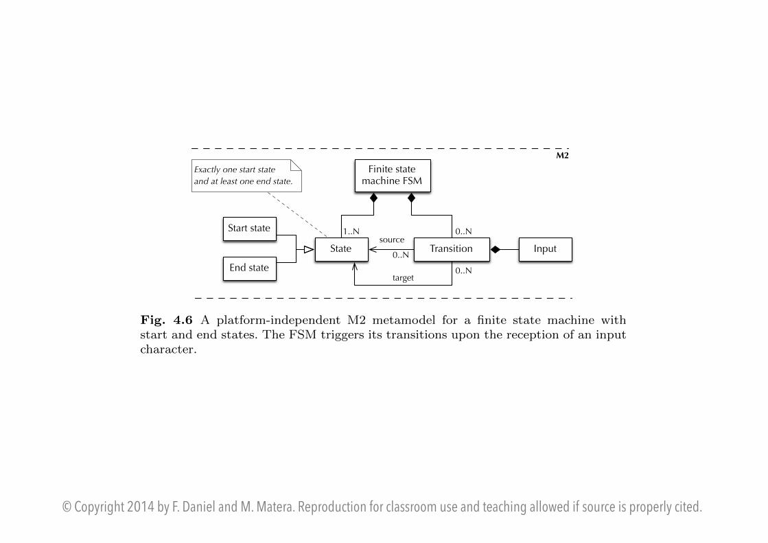
In Figure 4.6 we show a generic metamodel for a finite state machine (FSM)that reacts to the reception of simple characters in input, causing the FSMto transition from one state to another without producing any own output inresponse. We express the metamodel via a common UML class diagram at themetalevel M2, yet other formalisms could also be used to express the sameinformation (e.g., the BNF). According to the metamodel, a FSM comprisesone or more states and a set of transitions with a source and a target stateand an input that triggers them. Two special states, a start state and an endstate further denote the starting and accepting states of the FSM.
source1..N
Finite state machine FSM
State Transition
target
0..NStart state
End state
Exactly one start state
and at least one end state.
0..N
0..N
M2
Input
Fig. 4.6 A platform-independent M2 metamodel for a finite state machine withstart and end states. The FSM triggers its transitions upon the reception of an inputcharacter.
The metamodel in the figure is self-contained and does not depend on anyadditional formalism beyond UML. It is an instance of the UML metamodeland, hence, syntactically at metalevel M1 (in terms of UML). However, sincewe use it here as metamodel for the definition of our own modeling language,semantically, that is, from the point of view of MDSD, the metamodel is atmetalevel M2. The model describes all and only those constructs that arenecessary for the modeling of FSMs.
We could have defined a metamodel that is completely at metalevel M2by specializing the metamodel of UML itself (the so-called base metamodel)with the constructs necessary to model FSMs (e.g., by specializing theUML::Class construct). The implication of this choice would have been

© Copyright 2014 by F. Daniel and M. Matera. Reproduction for classroom use and teaching allowed if source is properly cited.
4.3 Metamodeling 87
that the resulting modeling language would in principle have the whole ex-pressive power of UML, if the developer does not restrict himself (or themodeling tool does so) to using only those constructs of the extended UMLmetamodel that indeed refers to FMSs only. That is, specializing the UMLmetamodel means inheriting the whole complexity of UML. The benefit ofdoing so is a MOF-compliant metamodel and UML tool support.
Independently of which of the two options we choose, it is important tonote that the metamodel contains both modeling constructs and constraints.In Figure 4.6 we simply use natural language to state that, in order for aFSM to be correct, it must contain at least one start state and at least oneend state. In the context of UML, the more formal version of this statementwould be expressed in the Object Constraint Language (OCL) [212], whichcan also be evaluated by advanced UML MDSD tools to check the expressedproperties. The constructs of the metamodel together with its constraintsdefine the so-called static semantics of the model.
4.3.2.2 MOF-based metamodel
Instead of specializing the UML metamodel, we can obtain a MOF-compliantmetamodel for our modeling language also if we directly use the MOF to spec-ify the metamodel. That is, we neglect the whole metamodel of UML anddefine our very own metamodel in terms of instances of MOF constructs.Figure 4.7 depicts a simplified version (without attributes and detailed rela-tionship descriptions) of the Essential MOF (EMOF) model [215], the coreof the MOF and the starting point for MOF-compliant metamodel specifica-tions.
Class AssociationProperty
Classifier
Type Operation
StructuralFeature
0..N0..N
0..N
M3
TypeGeneralization
ParameterMultiplicityElement
TypedElement
Feature TypedElement
MultiplicityElement
0..N 0..N
0..N
superclass
0..N
0..N 0..N
opposite 0..1 0..1
Fig. 4.7 A simplified version of the EMOF package, the core of the MOF [215].

© Copyright 2014 by F. Daniel and M. Matera. Reproduction for classroom use and teaching allowed if source is properly cited.
88 4 Model-Driven Software Development
Figure 4.8 provides an example of how our FSM metamodel could look likeas an instance of the MOF (still using a UML class diagram to instantiateMOF elements). MOF is at metalevel M3; our metamodel at metalevel M2.
sourceState Transition
target
0..N
Start state
End state
Exactly one start state
and at least one end state.
0..N
MOF::Class
M3
M2
<<instance of>>
MOF::Association
MOF::Property
<<instance of>>
<<instance of>>
Input
<<instance of>>
Fig. 4.8 A metamodel for a FSM defined as instance of the Meta Object Facil-ity (MOF) [215] with some <<instance of>> relationships highlighted: states andtransitions are instances of MOF::Class, relationships of MOF::Association, andattributes of MOF::Property.
UML is not the only MOF-compliant modeling language. With the meta-model in Figure 4.8 we developed our own MOF-compliant modeling lan-guage. The benefit of doing so comes in the form of well-defined MOF se-mantics and MOF-related tools and instruments we can reuse, such as MOF-enabled modeling tools and XMI for the interchange of model instances.Defining metamodels as MOF instances is typically only used for very bigmodeling languages that cover a specific application or technological domainand that aim to create consensus among multiple partners participating in thedefinition of the new modeling language. An example of this is the CommonWarehouse Metamodel (CWM).
4.3.2.3 UML profiles
The use of the MOF allows both the specification of own, custom meta-models as well as the extension of the base UML metamodel, which itself isexpressed in terms of MOF. Yet, UML also comes with its very own exten-sion mechanism, UML profiles. Profiles allow the definition of UML-based,domain-specific modeling languages. Since version 2.0 of UML, profiles aredefined formally as part of the UML metamodel. This means that concreteprofile definitions are at metalevel M1 from a UML point of view, while theyare at metalevel M2 from a MDSD point of view. After all, profiles are meta-models of modeling languages; it’s just that they are expressed via UML.

© Copyright 2014 by F. Daniel and M. Matera. Reproduction for classroom use and teaching allowed if source is properly cited.
4.3 Metamodeling 89
Profiles are based on stereotypes, tagged values, and constraints:
• Stereotypes: Stereotypes are UML’s mechanism to extend the basic vo-cabulary of UML with elements with custom meaning and properties,starting from the core elements of UML itself (e.g., UML classes). Forinstance, in Figure 4.9 we define stereotypes (graphically represented bythe <<stereotype>> adornment) for states and transitions as extensionsof the UML::Class concept. The figure uses the extension relationshipintroduced in UML 2.0 for the definition of stereotypes [217].
• Tagged values: A stereotype can have attributes to define additional prop-erties for new vocabulary elements. Being conceptually expressed at met-alevel M2, these attributes do not refer to attributes of runtime instances,but to attributes or properties of the modeling constructs at the M1 level,i.e., metadata from the point of view of the model. There are di↵erent waysof rendering tagged values in an M1 model instance, e.g., inside commentsattached to the respective modeling element. The purpose of tagged valuesis typically that of providing the code generator with additional instruc-tions on how to generate code or transform models or to provide meansfor configuration management.
• Constraints: As for all metamodels in general, also profiles allow the use ofOCL for the specification of static constraints further refining the possibleuse of the modeling constructs at metalevel M1.
<<stereotype>>
State<<stereotype>>
Transition
There must be
exactly one start
state and at least
one end state.
<<metaclass>>
Class
M2
UML 2.0
extension
relationship
<<metaclass>>
Association
Must have one
property of type Input
<<stereotype>>
Input
<<metaclass>>
Property
<<stereotype>>
Start state<<stereotype>>
End stateConnects
only states
Fig. 4.9 A metamodel for a FSM defined as UML 2.0 profile. Syntactically, UMLprofiles are at the metalevel M1, yet semantically they are at metalevel M2, as profilesspecialize the UML metamodel (e.g., UML::Class).
The simple UML profile in Figure 4.9 expresses our metamodel of the FSMby means of stereotypes and constraints that extend metaclasses of the UMLbase model with custom meaning. The fact that transitions have a source anda target state is expressed (i) implicitly by extending the UML associationelement, which represents a relationship among two classes, and (ii) explicitly

© Copyright 2014 by F. Daniel and M. Matera. Reproduction for classroom use and teaching allowed if source is properly cited.
90 4 Model-Driven Software Development
Class AssociationProperty
RelationshipClassifier
TypeOperation
StructuralFeature
0..N0..N
superclass
1..N
M2
0..N
0..N
0..10..1
0..N
0..10..N
Fig. 4.10 A simplified excerpt of the Classes diagram of the Constructs package ofthe UML metamodel [217], the starting point for the definition of UML profiles.
by the constraint that limits transitions to connect only states. Associationsmay further have properties; the second constraint of the transitions requireseach instance of a transition to have one input property.
Knowing the available UML constructs (defined in the Constructs packageof the UML specification [217]), i.e., its metaclasses, allows the definition ofrelatively concise UML profiles to express metamodels. In Figure 4.10, weshow a very simplified excerpt of the UML metamodel, which is the referencefor the profile in Figure 4.9. UML profiles are typically used to define modelinglanguages for limited domains. UML tools partly support profiles and are ableto enforce OCL constraints at modeling time.
4.3.3 Modeling syntax
The last ingredient for the specification of a modeling language is the syntaxof the language. While the metamodel expresses which modeling constructsthe language can use and the respective static semantics (two core conceptualingredients), the syntax is the “user interface” of the modeling language.Just like for any other graphical formalism, the choice of how to visualizemodeling constructs strongly a↵ects the readability and understandability ofthe modeling language and, hence, determines its success.
We specifically focus on the graphical modeling syntax a developer mayuse inside a modeling tool. Of course, all the models designed by the de-veloper also require an equivalent serialization for their persistent storage,e.g., inside a model repository. In the context of MOF-compliant modelinglanguages, this serialization could be XMI, which provides the mapping ofMOF constructs to XML already for free. However, also formats that aredi↵erent from XMI could be used for this purpose, depending on the specificsof each individual MDSD project. We do not want to provide any restriction

© Copyright 2014 by F. Daniel and M. Matera. Reproduction for classroom use and teaching allowed if source is properly cited.
4.3 Metamodeling 91
regarding the serialization of models; however, XML-based formats typicallyfacilitate the last step in the MDSD process, i.e., code generation, which wetalk about in the next section.
4.3.3.1 Abstract syntax
The first approach to assign a syntax to a metamodel like the one of our FSM,is to use a UML object diagram, which allows the representation of instancesof metamodel elements. For example, in Figure 4.11 we model a state machinewith four states (S1-S4) and four transitions (T1-T4), respectively triggeredby the inputs “a”, “b”, “c”, and “d”. S1 is a start state; S4 an end state, S2and S3 are intermediate states.
S1 :Start state
S2 :State
S3 :State
: Transition
: Transition
: Transition
: TransitionS4 :
End state
M1
source target source
target
source
target
source target
a : Input
b : Input
c : Input
d : Input
Fig. 4.11 A model instance of the finite state machine defined in Figure 4.6 using aUML object diagram as modeling syntax.
It is clear that the object diagram notation allows a developer to developan M1 model instance, but it is also relatively evident that this notation isneither intuitive nor very expressive. The object diagram in fact still providesonly an abstract syntax to a modeling language.
4.3.3.2 Concrete syntax
In Figure 4.12, instead, we used a more intuitive and conventional syntax tomodel a FSM, i.e., circles for states, directed arrows for transitions, labelsfor the inputs for transitions, a node with a transition without source nodefor the start node, and a circle with double borders for the end node. It isself-evident that this kind of syntax is much more suitable to the domain offinite state machines and that the right graphical notation improves model

© Copyright 2014 by F. Daniel and M. Matera. Reproduction for classroom use and teaching allowed if source is properly cited.
92 4 Model-Driven Software Development
S1
S2
S3
S4
a
bc
d
end state
identifies start state
transition
input
Fig. 4.12 A model instance of the finite state machine defined in Figure 4.6 usingan own, more intuitive modeling syntax.
readability and understandability. We call a syntax that defines a domain-specific modeling notation for each modeling construct a concrete syntax.
Another example of expressive concrete syntax is represented by WebML[69], which represents web pages as rectangular boxes, which contain contentunits represented as boxes with icons that recall the visualization formatof content (e.g., lists or checkboxes). Hyperlinks are represented as arrowsconnecting pages and units, and so on.
4.4 From the Model to the Application
As explained in the beginning of this chapter, the goal of MDSD is not just touse models as application specifications that aid manual development but toleverage on models to automate some of the manual work by the developer.The two types of work that can be automated are model transformations andcode generation. The former refers to the transformation from one model intoanother model, e.g., from a PIM to a PSM or from one PIM to another PIM.The latter refers to the generation of application code out of a given model(typically the PSM or in some cases also the PIM).
4.4.1 Model-to-model transformations
OMG’s MDA proposal with its various levels of abstraction (PIM, PSM,PDM) subsumes a development process that starts from the PIM (or CIM),refines such into a PSM with the help of a PDM, and finally into applicationcode. That is, the idea of transforming one model into another, typicallyan abstract model into a less abstract one, is an integral part of the MDAproposal. AC-MDSD, instead, is typically based on one single applicationmodel and does not foresee the use of model-to-model transformations.

© Copyright 2014 by F. Daniel and M. Matera. Reproduction for classroom use and teaching allowed if source is properly cited.
94 4 Model-Driven Software Development
Application
Platform
Individual code
Application model
Repetitive code
Code generator
Generation templates
Generative architecture
usesConfigura-tion files
Infrastructure componentsInfrastructure componentsInfrastructure components
Fig. 4.13 The typical MDSD code generation process based on code templates.Depending on the platform features and the modeled application, either configurationfiles or code or both are generated; individual code may be plugged in manually.
as composed of all those code artifacts and software components (e.g., dataaccess APIs, technology adapters, data transformers, user interface gener-ation logic, etc.) that are reusable inside the domain of a whole family ofapplications. The opportunity to reuse artifacts and components in the de-velopment of multiple applications of a same family justifies the investmentin the development of the platform in the first place.
As a consequence, generating code from a model is not as naive as to gen-erate the complete code of the application specified in a model from scratch.A large part of is functionalities is already available as reusable componentsinside the target platform, and the code generation process only needs toprovide these components with suitable configuration settings and/or to gen-erate code that makes use of them.
As illustrated in Figure 4.13, there is generally however an additional kindof artifact that requires our attention: individual code, i.e., custom code andfunctionality, which can be programmed manually and plugged into the ap-plication to be generated. Especially in the context of AC-MDSD, where thefocus of the modeling e↵ort is on the careful selection and configuration ofreadily available architectural elements, it is not given for granted that allapplication capabilities expressed in the model are already supported by theunderlying platform. In order to overcome possible lacks of functionality, boththe platform and the model must support suitable extensibility mechanisms,which allow the developer to plug in custom application logic. The final vi-sion of MDA with its support for executable UML, instead, would allow thedeveloper to specify any kind of application logic in the model and to gener-ate the respective code from it, practically turning the model into code. Yet,this vision is not yet reality, and we are not sure it will ever become.

© Copyright 2014 by F. Daniel and M. Matera. Reproduction for classroom use and teaching allowed if source is properly cited.
4.5 Summary and Bibliographic Notes 97
4.5 Summary and Bibliographic Notes
We summarize the key concepts as illustrated in Figure 4.14. A model is aninstance of a metamodel, which, in turn, is an instance of a meta-metamodel.That is, the meta-metamodel tells how to construct a metamodel; the meta-model tells how to construct a model. The metamodel assumes a key rolein the MDSD process, in that it is the basis for the design of the modelinglanguage used to develop models. It has an abstract syntax and static se-mantics. The abstract syntax specifies how the modeling language’s structurelooks like. The modeling language has a concrete syntax, which realizes theabstract syntax and provides it with concrete constructs (e.g., XML elements,graphical constructs, textual instructions, or similar). The concrete syntax iswhat the parser of a model transformer or interpreter reads, the abstractsyntax expresses how they structure the parsed model internally (in mem-ory). The static semantics of the metamodel defines the requirements for thewell-formedness of models (e.g., that a content unit construct can only occurinside a page construct). The dynamic semantics of the modeling languagedefines how models are processed and eventually turned into applications,a logic the developer must intimately know in order to be able to correctlyexpress a target application via a model.
We discussed MDSD in this chapter, since MDSD is the basis for manymashup tools and platforms and discussing them, first of all, requires the nec-essary understanding of MDSD principles. We have seen that a well-designedMDSD approach comes with the power of alleviating the developer fromsome development tasks (typically, the most repetitive and annoying ones)and speeding up development. However, MDSD does not come without prob-
Meta-metamodel
Metamodel
Model
<<instance of>>
<<instance of>>
Abstract syntaxStatic
semantics
Concrete syntax
Modeling language
Dynamic semantics
has
has
expressed in
complies withgets meaning from
has
has
extendsbased on
defined on
Fig. 4.14 Summary of the key concepts of MDSD.