d20 status input module - ge grid solutions · d20 status input module overview the d20 status...
TRANSCRIPT

GEDigital Energy
g imagination at work
D20 Status Input ModuleOverviewThe D20 Status module is composed of two detachable modules, WESTERM D20 S and WESDAC D20 S. The bottom module, WESTERM D20 S, is where all field wirings are terminated. The top module, WESDAC D20 S, processes the data acquired and communicates this to the main D20 processor, see Figure 2.
The WESTERM D20 S module is the termination for the WESDAC D20 S status input module. All field, I/O, and power terminations for the WESDAC D20 S are made on the WESTERM D20 S. Up to 64 digital inputs can be accommodated on the compression type terminations. Through the use of voltage dropping resistors, inputs in the range of 12 VDC to 130 VDC can be handled.
Capacitors and varistors are equipped to provide Surge Withstand Capability (SWC) as well as impulse protection on all field inputs. The inputs are separated into 8 groups of 8 status inputs each. Each group has its own common return and is electrically isolated from the other groups. Inputs are provided with two compression type terminals for field connections.
All inputs are bipolar, thus accommodating positive and negative ground systems. Each group can be configured with a group common or for contact wetting. The contact wetting can be supplied either from the input to the WESDAC D20S or from an external supply. The wetting supply is fused. Two DB 9 connectors are provided to allow daisy chaining of the D.20 links. The link provides the communication channel over which the main D20 CPU processor, the WESDAC D20 M, can communicate with the WESDAC D20 S. Power for the WESDAC D20 S is also provided over the same cable assembly. The power is fused and filtered by passive components on the WESTERM D20S.
A single DB 9 connector is provided for the WESMAINT D20 maintenance port . This port allows communications between a VT 100 terminal or emulator, and the WESDAC D20 S. Module input data as well as diagnostic information can be passed over the maintenance port.
The address jumper block for the WESDAC D20 S is located on the WESTERM D20 S. The address on the jumper block corresponds to the module’s slave address on the D.20 link.
The WESDAC D20 S is physically mounted on and electrically connected to the WESTERM D20 S through three 40 pin connectors. The two modules are mounted on a 19 inch rack and all field terminations are wired into the WESTERM D20 S.
Only passive components are mounted on the WESTERM D20 S leaving all the active components on the WESDAC D20 S.
This arrangement simplifies in field repair of the unit since the WESDAC D20 S can be replaced without disturbing any of the field wiring.
Efficient, Cost Effective I/O Solutions• The I/O modularity allows for efficient
distributed I/O installations - minimizing wiring and enclosure requirements; this eliminates panel and reduces cost
• The active/passive design of the WESDAC/WESTERM I/O modules allows users to quickly test, commission, and troubleshoot via hot swappable WESDAC modules, without disturbing wiring connections; this significantly speeds up and simplifies maintenance activities
Ease of Use• To first time users, both the software
configuration setup and hardware installations are trivial; this makes it simple to install and maintain the I/O modules
Flexible and Reliable Operations• The digital I/O module can be easily
configured to accommodate different system point types such as single, double, transition or Form C counters
• D20S supports up to 64 discrete digital inputs that are bipolar and optically isolated
• I/O modules are available to be ordered with either a DNP3 communication protocol option or a Standard/ Redundant D.20 link option – the D.20 link is a GE proprietary protocol

GEDigitalEnergy.com2
Distributed I/O ArchitectureThe D20 Remote Terminal Unit (RTU) design is based on a distributed-processing architecture including real-time data acquisition and control software. These I/O modules can be located close to the primary equipment being monitored and controlled as they receive and send data back to the master D20 main processor.
The I/O modules are intelligent modules that contain on-board microprocessors and are configured as slave devices to the D20 main processor. In the Figure 1 pictorial setup, specific I/O processing is distributed throughout the D20 RTU to the appropriate I/O modules.
The I/O modules support two communication protocols: (1) DNP 3 protocol, and (2) high speed, high-level data link controller (D.20 Link, HDLC) protocol. The peripheral modules have serial communication ports and various types of field connections.
The hardware construction of each remote I/O module type is similar (see Figure 2.)
Figure 2: Architecture of I/O logic and termination panels
Figure 1: Simple architecture of I/O modules communicating to the D20 RTU
WESDAC Logic Panel
Acrylic Display Cover
WESTERM Terminal Panel
Terminal Blocks Metal Mounting Plate
SCADA Masters

GEDigitalEnergy.com 3
Data ProcessingD20 status modules provide specialized processing and storing/buffering functions for digital inputs and pulse accumulator inputs by gathering data from field sources.
This processing provides flexible, reliable, robust operation and is configurable on a per-point or per-system basis.
Table 1: Input Processing
TYPE DESCRIPTION
Digital Input • Software debouncing• Chatter filtering• Report limiting
The D20S can accept up to 64 digital inputs, each of which can be configured from a downloaded database to be processed as one of the following:
• Status and alarm inputs
• Status inputs with change of state detection (COS)
• Sequence of events (SOE) using time-tagged COS
• Binary-Coded Decimal or parallel inputs
• Pulse accumulator or counter inputs
• Pulse duration inputs
The 64 digital inputs are organized in eight groups of eight electrically isolated inputs, each group with a common return. Each input is photo-coupled. For the D.20 modules, communicating via HDLC, the microprocessor scans each input at one millisecond intervals and provides selectable debounce of 4 to 255 ms. Changes are time-tagged to a resolution of one millisecond and placed in a first in - first out (FIFO) buffer for transmission to the D20 main processor.
Time-tagged changes are reported in chronological order. Non-time-tagged changes are placed in a separate FIFO buffer and reported upon request.
Termination TypesD20 Status module can be ordered with the following field termination options:
Table 2: D20 Status Input Termination Types
PERIPHERAL I/O SUPPORT TERMINATION
D20S 64 digital inputs, standard version Compression
D20SD 64 digital inputs, standard version DB25
D20SX 64 digital inputs, standard version Disconnect
D20SB 64 digital inputs, standard version Barrier
D20SZ 64 digital inputs, high-voltage version HV Compression
Technical Specifications
Table 3: D20S Specifications
ITEM DESCRIPTION
Processor 8 bit Freescale 68HC11 MPU
Clock 2 MHz MPU clock
Memory • 32 KB EPROM• 24 KB static RAM• 512 bytes EEPROM
Inputs 64 bipolar inputs in 8 groups of 8
Point Types • Status/alarm with COS detection
• SOE
• Form A or Form C pulse accumulator (16 bit binary counter)
• Binary coded decimal
• Pulse duration
Current Burden ±3 to ±6 mA per input
Scan Rate 1.0 ms
Debounce Selectable 0 to 255 ms
SOE Time Resolution 1.0 ms
Contact Wetting ±12, ±24, ±48, ±125 V
Overload Rating 500 VDC (common mode to ground)
Component Isolation Rating 1500 Vrms
Dielectric Rating 1000 VDC
D.20 Link Ports 2
Maintenance Port 9600 baud, RS-232
Power Requirements 20-60 VDC, 3 W typical
Size 19" x 5.25" x 2.5"
LED Indicators • Common LEDs• For each input point, a RED LED to
indicate the ON/OFF state of the point
GEDigitalEnergy.com4
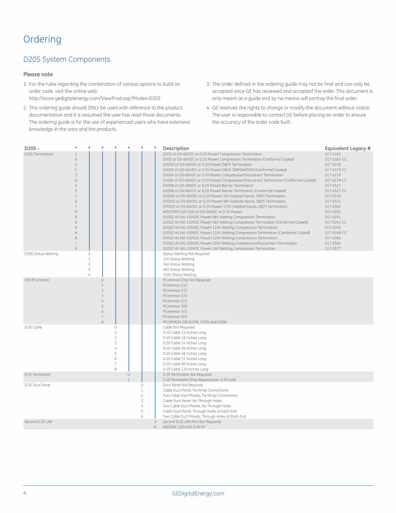
Ordering
D20S System Components
Please note
1. For the rules regarding the combination of various options to build an order code, visit the online web: http://store.gedigitalenergy.com/ViewProd.asp?Model=D20S
2. This ordering guide should ONLY be used with reference to the product documentation and it is assumed the user has read those documents. The ordering guide is for the use of experienced users who have extensive knowledge in the area and the products.
3. The order defined in the ordering guide may not be final and can only be accepted once GE has reviewed and accepted the order. This document is only meant as a guide and by no means will portray the final order.
4. GE reserves the rights to change or modify the document without notice. The user is responsible to contact GE before placing an order to ensure the accuracy of the order code built.
D20S - * * * * * * * Description Equivalent Legacy #D20S Termination 1 D20S LV (20-60VDC or D.20 Power) Compression Termination 517-0165
B D20S LV (20-60VDC or D.20 Power) Compression Termination (Conformal Coated) 517-0165-CC2 D20SD LV (20-60VDC or D.20 Power) DB25 Termination 517-0179C D20SD LV (20-60VDC or D.20 Power) DB25 TERMINATION (Conformal Coated) 517-0179-CC3 D20SX LV (20-60VDC or D.20 Power) Compression/Disconnect Termination 517-0219D D20SX LV (20-60VDC or D.20 Power) Compression/Disconnect Termination (Conformal Coated) 517-0219-CC4 D20SB LV (20-60VDC or D.20 Power) Barrier Termination 517-0327E D20SB LV (20-60VDC or D.20 Power) Barrier Termination (Conformal Coated) 517-0327-CC5 D20SDI LV (20-60VDC or D.20 Power) 24V Isolated Inputs, DB25 Termination 517-03306 D20SDI LV (20-60VDC or D.20 Power) 48V Isolated Inputs, DB25 Termination 517-03317 D20SDI LV (20-60VDC or D.20 Power) 125V Isolated Inputs, DB25 Termination 517-0262M WESTERM D20 OSD LV (20-60VDC or D.20 Power) 517-02528 D20SZ HV (40-150VDC Power) 48V Wetting Compression Termination 517-0241G D20SZ HV (40-150VDC Power) 48V Wetting Compression Termination (Conformal Coated) 517-0241-CC9 D20SZ HV (40-150VDC Power) 110V Wetting Compression Termination 517-0249H D20SZ HV (40-150VDC Power) 110V Wetting Compression Termination (Conformal Coated) 517-0249-CCA D20SZ HV (40-150VDC Power) 220V Wetting Compression Termination 517-0266I D20SZ HV (40-150VDC Power) 220V Wetting Compression/Disconnect Termination 517-0366K D20SZ HV (40-150VDC Power) 24V Wetting Compression Termination 517-0377
D20S Status Wetting U Status Wetting Not Required1 12V Status Wetting2 24V Status Wetting3 48V Status Wetting4 130V Status Wetting
D20 PCommon U PCommon Chip Not Required1 PCommon 2122 PCommon 2133 PCommon 2204 PCommon 2215 PCommon 3006 PCommon 3017 PCommon 3058 PCOMMON 306 (D20A, D20S and D20K)
D.20 Cable U Cable Not Required1 D.20 Cable 12 Inches Long2 D.20 Cable 18 Inches Long3 D.20 Cable 24 Inches Long4 D.20 Cable 36 Inches Long5 D.20 Cable 48 Inches Long6 D.20 Cable 72 Inches Long7 D.20 Cable 96 Inches Long8 D.20 Cable 120 Inches Long
D.20 Terminator U D.20 Terminator Not Required1 D.20 Terminator (One Required per D.20 Link)
D.20 Duct Panel U Duct Panel Not Required1 Cable Duct Panel, Tie Wrap Connections2 Two Cable Duct Panels, Tie Wrap Connections3 Cable Duct Panel, No Through Holes4 Two Cable Duct Panels, No Through Holes5 Cable Duct Panel, Through Holes at Each End6 Two Cable Duct Panels, Through Holes at Each End
Second D.20 LAN U Second D.20 LAN Port Not RequiredA WESDAC D20 ASK D.20 I/F

GEDigitalEnergy.com 5
D20S Spare Components
Please note
1. For the rules regarding the combination of various options to build an order code, visit the online web: http://store.gedigitalenergy.com/ViewProd.asp?Model=D20S+Spare+Parts
2. This ordering guide should ONLY be used with reference to the product documentation and it is assumed the user has read those documents. The ordering guide is for the use of experienced users who have extensive knowledge in the area and the products.
3. The order defined in the ordering guide may not be final and can only be accepted once GE has reviewed and accepted the order. This document is only meant as a guide and by no means will portray the final order.
4. GE reserves the rights to change or modify the document without notice. The user is responsible to contact GE before placing an order to ensure the accuracy of the order code built.
D20S - * * * * * * * * * DescriptionModule Type U None (Need ONLY RNET Voltage Adapter Packs)
3 DNP 3 I/O ModuleD WESDAC ModuleT WESTERM Module
Input Voltage to Module U None (Need ONLY RNET Voltage Adapter Packs)H High Voltage (40-150VDC)L Low Voltage (20-60 VDC or D.20 Link Power)
Termination Type U NoneB Barrier Termination TypeD DB25 Termination TypeP Compression Termination TypeX Compression/Disconnect Terminatiion Type
Environmental Protection U NoneC Conformal CoatE Epoxy-Conformal Coat
D20S RNET Type U NoneG Built-in RNETSI Isolated Built-in RNETSS Selectable RNETS
D20S RNET Voltage U None012 12V Adapter Packs024 24V Adapter Packs048 48V Adapter Packs110 110V Adapter Packs125 125V Adapter Packs220 220V Adapter Packs
D.20 Link U None R WESTERM Redundant D.20 Link & Dual Power Supply Option (540-0313) L WESDAC Redundant D.20 Link & Dual Power Supply Option (540-0207)S Standard D.20 Link [ For Module type T, or D]
PCOMMON U None1 PCommon 212 (SBA0001/00)2 PCommon 213 (SBA0003/00)3 PCommon 220 (SBA0004/00)4 PCommon 221 (SBA0007/00)5 PCommon 300 (SBA0005/00)6 PCommon 301 (SBA0006/00)7 PCommon 305 (SBA0009/00)8 PCOMMON 306 (P010-0 VER.306)
DNP3 DI Input Points U None A Single PointB Double PointC Transition CounterD Form C Counter
g imagination at work
GE Digital Energy
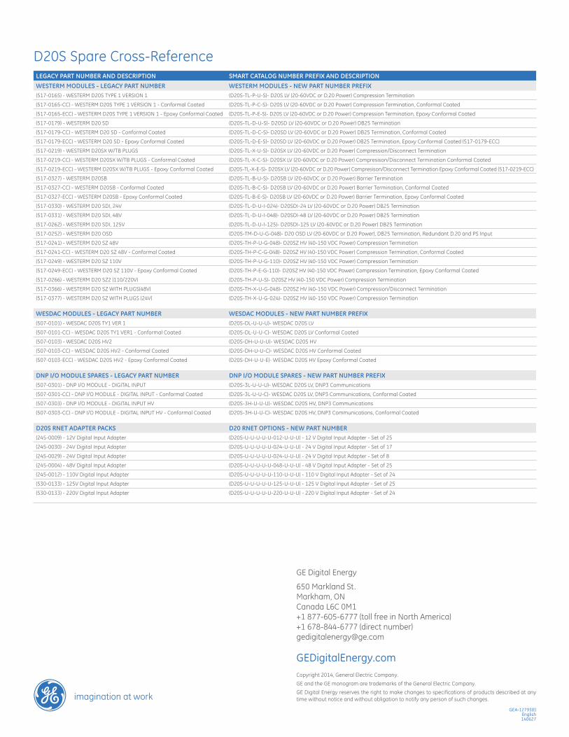
650 Markland St.Markham, ONCanada L6C 0M1 +1 877-605-6777 (toll free in North America)+1 678-844-6777 (direct number)[email protected]
GEDigitalEnergy.comCopyright 2014, General Electric Company. GE and the GE monogram are trademarks of the General Electric Company. GE Digital Energy reserves the right to make changes to specifications of products described at any time without notice and without obligation to notify any person of such changes.
GEA-12793(E)English 140627
D20S Spare Cross-ReferenceLEGACY PART NUMBER AND DESCRIPTION SMART CATALOG NUMBER PREFIX AND DESCRIPTIONWESTERM MODULES - LEGACY PART NUMBER WESTERM MODULES - NEW PART NUMBER PREFIX(517-0165) - WESTERM D20S TYPE 1 VERSION 1 (D20S-TL-P-U-S)- D20S LV (20-60VDC or D.20 Power) Compression Termination
(517-0165-CC) - WESTERM D20S TYPE 1 VERSION 1 - Conformal Coated (D20S-TL-P-C-S)- D20S LV (20-60VDC or D.20 Power) Compression Termination, Conformal Coated
(517-0165-ECC) - WESTERM D20S TYPE 1 VERSION 1 - Epoxy Conformal Coated (D20S-TL-P-E-S)- D20S LV (20-60VDC or D.20 Power) Compression Termination, Epoxy Conformal Coated
(517-0179) - WESTERM D20 SD (D20S-TL-D-U-S)- D20SD LV (20-60VDC or D.20 Power) DB25 Termination
(517-0179-CC) - WESTERM D20 SD - Conformal Coated (D20S-TL-D-C-S)- D20SD LV (20-60VDC or D.20 Power) DB25 Termination, Conformal Coated
(517-0179-ECC) - WESTERM D20 SD - Epoxy Conformal Coated (D20S-TL-D-E-S)- D20SD LV (20-60VDC or D.20 Power) DB25 Termination, Epoxy Conformal Coated (517-0179-ECC)
(517-0219) - WESTERM D20SX W/TB PLUGS (D20S-TL-X-U-S)- D20SX LV (20-60VDC or D.20 Power) Compression/Disconnect Termination
(517-0219-CC) - WESTERM D20SX W/TB PLUGS - Conformal Coated (D20S-TL-X-C-S)- D20SX LV (20-60VDC or D.20 Power) Compresison/Disconnect Termination Conformal Coated
(517-0219-ECC) - WESTERM D20SX W/TB PLUGS - Epoxy Conformal Coated (D20S-TL-X-E-S)- D20SX LV (20-60VDC or D.20 Power) Compresison/Disconnect Termination Epoxy Conformal Coated (517-0219-ECC)
(517-0327) - WESTERM D20SB (D20S-TL-B-U-S)- D20SB LV (20-60VDC or D.20 Power) Barrier Termination
(517-0327-CC) - WESTERM D20SB - Conformal Coated (D20S-TL-B-C-S)- D20SB LV (20-60VDC or D.20 Power) Barrier Termination, Conformal Coated
(517-0327-ECC) - WESTERM D20SB - Epoxy Conformal Coated (D20S-TL-B-E-S)- D20SB LV (20-60VDC or D.20 Power) Barrier Termination, Epoxy Conformal Coated
(517-0330) - WESTERM D20 SDI, 24V (D20S-TL-D-U-I-024)- D20SDI-24 LV (20-60VDC or D.20 Power) DB25 Termination
(517-0331) - WESTERM D20 SDI, 48V (D20S-TL-D-U-I-048)- D20SDI-48 LV (20-60VDC or D.20 Power) DB25 Termination
(517-0262) - WESTERM D20 SDI, 125V (D20S-TL-D-U-I-125)- D20SDI-125 LV (20-60VDC or D.20 Power) DB25 Termination
(517-0252) - WESTERM D20 OSD (D20S-TM-D-U-G-048)- D20 OSD LV (20-60VDC or D.20 Power), DB25 Termination, Redundant D.20 and PS Input
(517-0241) - WESTERM D20 SZ 48V (D20S-TH-P-U-G-048)- D20SZ HV (40-150 VDC Power) Compression Termination
(517-0241-CC) - WESTERM D20 SZ 48V - Conformal Coated (D20S-TH-P-C-G-048)- D20SZ HV (40-150 VDC Power) Compression Termination, Conformal Coated
(517-0249) - WESTERM D20 SZ 110V (D20S-TH-P-U-G-110)- D20SZ HV (40-150 VDC Power) Compression Termination
(517-0249-ECC) - WESTERM D20 SZ 110V - Epoxy Conformal Coated (D20S-TH-P-E-G-110)- D20SZ HV (40-150 VDC Power) Compression Termination, Epoxy Conformal Coated
(517-0266) - WESTERM D20 SZ2 (110/220V) (D20S-TH-P-U-S)- D20SZ HV (40-150 VDC Power) Compression Termination
(517-0366) - WESTERM D20 SZ WITH PLUGS(48V) (D20S-TH-X-U-G-048)- D20SZ HV (40-150 VDC Power) Compression/Disconnect Termination
(517-0377) - WESTERM D20 SZ WITH PLUGS (24V) (D20S-TH-X-U-G-024)- D20SZ HV (40-150 VDC Power) Compression Termination
WESDAC MODULES - LEGACY PART NUMBER WESDAC MODULES - NEW PART NUMBER PREFIX(507-0101) - WESDAC D20S TY1 VER 1 (D20S-DL-U-U-U)- WESDAC D20S LV
(507-0101-CC) - WESDAC D20S TY1 VER1 - Conformal Coated (D20S-DL-U-U-C)- WESDAC D20S LV Conformal Coated
(507-0103) - WESDAC D20S HV2 (D20S-DH-U-U-U)- WESDAC D20S HV
(507-0103-CC) - WESDAC D20S HV2 - Conformal Coated (D20S-DH-U-U-C)- WESDAC D20S HV Conformal Coated
(507-0103-ECC) - WESDAC D20S HV2 - Epoxy Conformal Coated (D20S-DH-U-U-E)- WESDAC D20S HV Epoxy Conformal Coated
DNP I/O MODULE SPARES - LEGACY PART NUMBER DNP I/O MODULE SPARES - NEW PART NUMBER PREFIX(507-0301) - DNP I/O MODULE - DIGITAL INPUT (D20S-3L-U-U-U)- WESDAC D20S LV, DNP3 Communications
(507-0301-CC) - DNP I/O MODULE - DIGITAL INPUT - Conformal Coated (D20S-3L-U-U-C)- WESDAC D20S LV, DNP3 Communications, Conformal Coated
(507-0303) - DNP I/O MODULE - DIGITAL INPUT HV (D20S-3H-U-U-U)- WESDAC D20S HV, DNP3 Communications
(507-0303-CC) - DNP I/O MODULE - DIGITAL INPUT HV - Conformal Coated (D20S-3H-U-U-C)- WESDAC D20S HV, DNP3 Communications, Conformal Coated
D20S RNET ADAPTER PACKS D20 RNET OPTIONS - NEW PART NUMBER (245-0009) - 12V Digital Input Adapter (D20S-U-U-U-U-U-012-U-U-U) - 12 V Digital Input Adapter - Set of 25
(245-0030) - 24V Digital Input Adapter (D20S-U-U-U-U-U-024-U-U-U) - 24 V Digital Input Adapter - Set of 17
(245-0029) - 24V Digital Input Adapter (D20S-U-U-U-U-U-024-U-U-U) - 24 V Digital Input Adapter - Set of 8
(245-0004) - 48V Digital Input Adapter (D20S-U-U-U-U-U-048-U-U-U) - 48 V Digital Input Adapter - Set of 25
(245-0012) - 110V Digital Input Adapter (D20S-U-U-U-U-U-110-U-U-U) - 110 V Digital Input Adapter - Set of 24
(530-0133) - 125V Digital Input Adapter (D20S-U-U-U-U-U-125-U-U-U) - 125 V Digital Input Adapter - Set of 25
(530-0133) - 220V Digital Input Adapter (D20S-U-U-U-U-U-220-U-U-U) - 220 V Digital Input Adapter - Set of 24