d0204 fcp m36 - urban track · representative sample of large and small european operators, in...
TRANSCRIPT

TIP5-CT-2006-031312 Page 1 of 54 URBAN TRACK Issued: 2009-08-30
D0204_FCP_M36.doc
DELIVERABLE D2.4 Related Milestone
CONTRACT N° 031312 PROJECT N° FP6-31312 ACRONYM URBAN TRACK
TITLE Urban Rail Transport PROJECT START DATE September 1, 2006
DURATION 48 months Subproject SP2 Cost effective track maintenance, renewal & refurbishment methods
Work Package WP2.2.1 Visual inspection & maintenance Proposal for "European Standard for Track
Inspection and Maintenance
Written by Kopf F., Maras I., Gasser F., Norkauer A., Ritz O., Krüger F., TU-Wien
D2S, STIB, ALSTOM, TTK, UITP, FCP
Date of issue of this report 2009-08-30 PROJECT CO-ORDINATOR Dynamics, Structures & Systems International D2S BE
PARTNERS Société des Transports Intercommunaux de Bruxelles STIB BE Alstom Transport Systems ALSTOM FR Bremen Strassenbahn AG BSAG DE Composite Damping Materials CDM BE Die Ingenieurswerkstatt DI DE Institut für Agrar- und Stadtökologische Projekte an
der Humboldt Universität zu BerlinASP DE
Tecnologia e Investigacion Ferriaria INECO-TIFSA ES Institut National de Recherche sur les Transports &
leur Sécurité INRETS FR
Institut National des Sciences Appliquées de Lyon INSA-CNRS FR Ferrocarriles Andaluces FA-DGT ES Alfa Products & Technologies APT BE Autre Porte Technique Global GLOBAL PH
Politecnico di Milano POLIMI IT Régie Autonome des Transports Parisiens RATP FR Studiengesellschaft für Unterirdische Verkehrsanlagen STUVA DE Stellenbosch University SU ZA Transport for London LONDON
TRAMS UK
Ferrocarril Metropolita de Barcelona TMB ES Transport Technology Consult Karlsruhe TTK DE Université Catholique de Louvain UCL BE Universiteit Hasselt UHASSELT BE
Project funded by the European Community under the SIXTH FRAMEWORK PROGRAMME PRIORITY 6 Sustainable development, global change & ecosystems International Association of Public Transport UITP BE
Union of European Railway Industries UNIFE BE Verkehrsbetriebe Karlsruhe VBK DE Fritsch Chiari & Partner FCP AT
Metro de Madrid MDM ES

TIP5-CT-2006-031312 Page 2 of 54 URBAN TRACK Issued: 2009-08-30
D0204_FCP_M36.doc
T A B L E O F C O N T E N T S 0. Executive summary .............................................................................................................................................. 4
0.1. Objective of the deliverable........................................................................................................................ 4 0.2. Strategy used and/or a description of the methods used with the justification thereof................. 4 0.3. Background info available and the innovative elements which were developed............................ 5 0.4. Problems encountered................................................................................................................................. 5 0.5. Partners involved and their contribution ................................................................................................ 6 0.6. Conclusions................................................................................................................................................... 7 0.7. Relation with the other deliverables (input/output/timing) .............................................................. 7
1. Standard Introduction.......................................................................................................................................... 9 2. Inspection .............................................................................................................................................................10
2.1. Track Inspection and Inspection Device ................................................................................................10 2.1.1. Track Geometry.................................................................................................................................10 2.1.2. Rail Inspection ...................................................................................................................................17
2.2. Inspection schedule ...................................................................................................................................24 3. Maintenance Measures ......................................................................................................................................26
3.1. Maintenance philosopies ..........................................................................................................................26 3.2. Servicing ......................................................................................................................................................27
3.2.1. Lubrication .........................................................................................................................................27 3.2.2. Surface cleaning.................................................................................................................................27 3.2.3. Cleaning ballast .................................................................................................................................28 3.2.4. Cleaning rail grooves........................................................................................................................28 3.2.5. Cleaning switches .............................................................................................................................28 3.2.6. Cleaning track drainage systems....................................................................................................28 3.2.7. Care and control of vegetation .......................................................................................................29 3.2.8. Snow clearing and ice removal in winter .....................................................................................29
3.3. Corrective Maintenance ............................................................................................................................29 3.3.1. Grinding..............................................................................................................................................29 3.3.2. Rail alignment....................................................................................................................................29 3.3.3. Maintenance of track covering........................................................................................................29 3.3.4. Build-up welding ..............................................................................................................................30
4. Recommendations for Intervention and alert limits.....................................................................................31 4.1. Scope.............................................................................................................................................................31 4.2. Definition of Categories ............................................................................................................................31 4.3. Intervention and alert limits.....................................................................................................................32
4.3.1. Track gauge........................................................................................................................................32 4.3.2. Horizontal alignment .......................................................................................................................32 4.3.3. Longitudinal Level............................................................................................................................32 4.3.4. Cross level ..........................................................................................................................................32 4.3.5. Twist ....................................................................................................................................................32 4.3.6. Grooves.................................................................................................................................................33

TIP5-CT-2006-031312 Page 3 of 54 URBAN TRACK Issued: 2009-08-30
D0204_FCP_M36.doc
4.4. Maintenance measures – review .............................................................................................................33 5. Operator remarks................................................................................................................................................35 6. LCC General Description...................................................................................................................................46
6.1. Considered Maintenance Measures in the Calculation.......................................................................48 6.2. Track types ..................................................................................................................................................48
6.2.1. Standard ballasted track ..................................................................................................................48 6.2.2. Covered track.....................................................................................................................................49
6.3. General UrbanTrack LCC Calculation conventions ............................................................................49 7. Working cycles and Costs .................................................................................................................................50
7.1. Ballasted Track ...........................................................................................................................................50 7.2. Covered Track ............................................................................................................................................51
8. Results...................................................................................................................................................................52 8.1. Summary Ballasted Track.........................................................................................................................52 8.2. Covered Track ............................................................................................................................................53
9. Bibliography.........................................................................................................................................................54

TIP5-CT-2006-031312 Page 4 of 54 URBAN TRACK Issued: 2009-08-30
D0204_FCP_M36.doc
0. EXECUTIVE SUMMARY
0.1. OBJECTIVE OF THE DELIVERABLE
The objective of the work package “Visual inspection & maintenance” was to create a comprehensive preliminary draft standard for urban railway tracks of public transport such as tram and metro. The draft standard was created with an emphasis on visual inspection and is applicable for all urban traffic network operators. The standard was aimed in particular at the small and medium size urban traffic network operators.
0.2. STRATEGY USED AND DESCRIPTION OF THE METHODS USED WITH THE JUSTIFICATION THEREOF
The draft standard was created using a step by step methodology. Initially a comprehensive study was undertaken, reviewing current and existing inspection and maintenance standards for both “heavy rail” and urban tracks. External experts from universities and operators assisted in compiling a preliminary draft standard. This draft standard formed the basis for the discussions with the operators and the consensus finding process. This unaltered preliminary standard forms the main part of this report (some minor changes have been made and these are highlighted in italic letters). All the collated comments and remarks refer to this original standard. The proposal document and a questionnaire were distributed to several operators Urban Track members and other experts to ascertain their views and opinions. However unfortunately the number of responses collected was very limited and therefore the strategy was altered. Subsequently it was decided to identify and contact relevant European operators and experts (with support of UITP) in the fields of inspection and maintenance to submit to them the draft standard. In addition, independent personal meetings were organised which provided a forum were relevant information, comments and remarks were collated through personal discussion.
The final step of the intended consensus finding process was a short survey with three questions:
• if the expert comments represent the official position of the represented operator,
• if the operator is interested in a European standard for inspection and maintenance and
• if the operator would support the standardisation work.
An anonymous reporting technique was used to avoid the judgement of the collected information and to show the various opinions of the interviewed operator experts without revealing confidential information.
This document contains the following chapters:
• A preliminary draft of the standard, changes after the operator survey are italic,
• Remarks and comments of the visited operator experts
• An example of the effect of the use of the standard on life cycle costs (LCC).

TIP5-CT-2006-031312 Page 5 of 54 URBAN TRACK Issued: 2009-08-30
D0204_FCP_M36.doc
0.3. BACKGROUND INFO AVAILABLE AND THE INNOVATIVE ELEMENTS WHICH WERE DEVELOPED
The new document should be based on the US transit maintenance procedures (APTA-RT-S-FS-002-02 dd-26-07-2004) based on visual inspection and established by the American Public Transportation Association (APTA).
The APTA-Code refers to the maintenance of “heavy rail” and therefore the code cannot be used directly to provide a standard for the specific inspection and maintenance needs of urban tracks. Urban tracks have specific differences to “heavy rail”, these include:
• greater diversity of track types (e.g. green track, embedded in roads),
• history of development of track, vicinity and environment,
• traditions in operating structures,
• diversity of the priority, running speed of the lines and the alignment parameters (e.g. longitudinal gradient, curve radius),
• variety of rolling stock,
• close proximity to the adjacent buildings, interference with the urban infrastructure (e.g. public services facilities and ducts),
• Influence of other traffic users (e.g. embedded in roads, shared use of track with “heavy rail”).
These significant differences between “heavy rail” and urban tracks and also the diversity within urban tracks make it difficult to utilise regulations of a selected operator as a universal comprehensive standard for urban public transport tracks. This non-exhaustive enumeration shows the difficulties and barriers for the harmonisation and standardisation work.
The developed draft document is a first attempt at standardising the “inspection & maintenance” for urban railway tracks of public transport such as tram and metro on a European level. There have been no previously published standards at a Euopean level, this is the first template of its kind.
0.4. PROBLEMS ENCOUNTERED
Significant effort and groundwork was required to collate the information from operators. The information gathered varied greatly from only general statements to very detailed comments. Discussions were sometimes difficult as the operator personnel undertaking the inspection and maintenance work typically was not accustomed to working with English language documents.
Through the course of these discussions further aspects have been identified that have made the definition of an uniform standard for track inspection and maintenance very difficult:
• Confidentiality of “in-house procedures” for inspection and maintenance,
• urban operators, which often belong to the local community are conscious of safeguarding regional jobs and are reluctant to support the global companies,

TIP5-CT-2006-031312 Page 6 of 54 URBAN TRACK Issued: 2009-08-30
D0204_FCP_M36.doc
• for global working component suppliers the market is small, diverse, competitive and not significant,
• apprehensiveness of operators towards European harmonisation and standardisation,
• for large operators, with vast in-house expertise and sophisticated regulations and procedures concerning the track – rolling stock interaction, a harmonised standard would be either irrelevant or a step backwards
From discussions with train operators we are unable to present a uniform standard of sufficient depth, reliability and quality.
0.5. PARTNERS INVOLVED AND THEIR CONTRIBUTION
The following list shows the contacted operators. The list includes partners in the Urban Track project, members of the operator network and some that are not integrated in the project. It should be a representative sample of large and small European operators, in different regions, languages and operation philosophies.
• Vienna (Wiener Linien GmbH)
• Graz (GVB Grazer Verkehrsbetriebe Grazer Stadtwerke AG Verkehrsbetriebe)
• Dresden (DVB Dresdner Verkehrsbetriebe AG)
• Karlsruhe (VBK Verkehrsbetriebe Karlsruhe)
• Brehmen (bsag Brehmer Straßenbahn AG)
• Brussels (STIB Société des Transports Intercommunaux de Bruxelles and De Lijn)
• Paris (RATP Régie autonome des transports Parisiens)
• Strasbourg (Compagnie des Transports Strasbourgeois – CTS)
• Porto (Metro do Porto, SA)
• Barcelona (TMB Transport metropolitans de Barcelona)
• Madrid (Metro de Madrid)
• Birmingham (Centro Midland Metro Birmingham)
• London (London Trams)
• Naples (Metronapoli)
• Bergen (bybanen, NSB lokaltog)
• Helsinki (YTV)
• Budapest (BKV Budapesti Transport)
• Warsaw (Tramwaje Warszawskie)
• Prague (DPP Dopravní podnik hl. M. Prahy)

TIP5-CT-2006-031312 Page 7 of 54 URBAN TRACK Issued: 2009-08-30
D0204_FCP_M36.doc
• Brno (Dopravní podnik města Brna)
We are very thankful for the time invested by the experts of these opertors and for their comments, remarks, discussions and delivered information.
0.6. CONCLUSIONS
A preliminary draft standard for urban railway tracks of public transport was developed.
The result of the survey to the operators showed only moderate interest to the standardisation and rather opposition within significant operators.
In conclusion a standardisation is not recommended, however the document could be helpful as voluntary “standard guidelines” for operators creating their own “in-house procedure”. UITP will form out of this work a “UITP recommendation”.
0.7. RELATION WITH THE OTHER DELIVERABLES (INPUT/OUTPUT/TIMING)
There is a relationship to the deliverable D4.3b which includes the LCC considerations.

TIP5-CT-2006-031312 Page 8 of 54 URBAN TRACK Issued: 2009-08-30
D0204_FCP_M36.doc
Proposal of European Standard for
Track Inspection and Maintenance
TIP5-CT-2006-031312 Page 9 of 54 URBAN TRACK Issued: 2009-08-30
D0204_FCP_M36.doc
1. STANDARD INTRODUCTION 4.1, 9.5 (these numbers refer to anonymous operator comments in chapter 5 collected during the consensus building process)
Inspection is the checking or testing for condition, performance and safety of equipment against established standards.
To provide safe operating as well as to sustain availability of the infrastructure, inspection is essential. Moreover it is not only the basis for further maintenance measures but also for the implementation of LCC-management. Only through a strategic measurement and documentation programme, the operator of an urban transit network can reach a high level of effectiveness and efficiency in wheel/rail operation and maintenance. Though the standard only deals with inspection and maintenance of the track, the wheel/rail interaction has a significant effect on abrasion of the track and therefore cannot be neglected.
As this standard addresses all infrastructure providers with inner-city/urban track networks according to Urban Track within the EU-countries and with respect to the diversity of track systems and vehicle types, the guidelines can only present a minimum level of requirements without limitation to set higher limits of quality. The size of network normally implicates different possibilities for the operator concerning man power, budget or technical equipment and priority of the track section (primary or secondary net). Therefore the foreseen standard concentrates on visual inspection and non-automated measurements. The standard defines what has to be measured but does not set any limits for procedures and equipment to carry out those measurements.
The following variables play a key role in determining rail-wear limits [1]:
► the highest permissible stresses in rails
► the geometry of contact between the flange and the rail or wheelset and track: two-point contact tends to produce poor steering on curves resulting in higher lateral force and higher rate of wheel/rail wear
► requirements regarding the quality of the track superstructure, especially for high speed services
► vehicle clearance and building (or “structural”) clearance
► if grooved rails are used, vertical wear of the rail head is further limited by the requirement that contact between the wheel flange and the bottom of the groove has to be avoided (exception: switches and crossings).
The proposal for a standard is structured in the following mean issues:
► Inspection
► Maintenance measures
► Recommendations for Intervention and alert limits
TIP5-CT-2006-031312 Page 10 of 54 URBAN TRACK Issued: 2009-08-30
D0204_FCP_M36.doc
2. INSPECTION
2.1. TRACK INSPECTION AND INSPECTION DEVICE1
4.2
The purpose of regular inspections is to determine any deviations from the track’s intended alignment and verify compliance with the respective set limit values. The expert opinion is acquired by means of sight and functional check and measurements. In principle, two types of inspections are used:
► visual inspection
► measurements (various procedures and equipment may be used, depending on the purpose and scope of the inspection)
Furthermore failure in alignment of track and rail defects can be detected through visual inspection (e.g. by means of binocular), test run over the track by experienced personnel, and feedback from operating personnel.
Regular visual examinations performed at set intervals can give an impression of the track’s basic condition to those who are responsible. In Figure 1 the individual elements are listed that require special attention in this context. Visual inspection can help to detect where further measurements are necessary.
Figure 1 Important track elements for visual inspection [1]
2.1.1. Track Geometry
Checking track geometry primarily entails taking regularly measurements of
1 This chapter is based on [1]

TIP5-CT-2006-031312 Page 11 of 54 URBAN TRACK Issued: 2009-08-30
D0204_FCP_M36.doc
► Track gauge
► Versed sine in curves
► Horizontal and vertical alignment
► Cross level and twist
2.1.1.1. Track gauge
9.6, 17.1
Definition [2]
Distance G between the gauge faces of the two adjacent running rails measured at a distance zp below the running surface (see Figure 2 and Figure 3).
1 GFT – common running surface
Figure 2 Track gauge – vignole rail
Figure 3 Track gauge – grooved rail
The track gauge will tend to widen through natural wear (primarily on curves). An initial phase of high abrasion (as the track’s shape conforms to passing wheel flanges) is followed by moderate and roughly linear wear. The wear rate is mainly influenced by the track radius, the load to which the section is subjected, and the surface hardness of the rail steel.

TIP5-CT-2006-031312 Page 12 of 54 URBAN TRACK Issued: 2009-08-30
D0204_FCP_M36.doc
The increasing tendency for bogies to run sideways on curves as wear increases then leads to a gradual third phase of abrasion, before the limit values are reached. Those limit values are generally forced by the track guiding demands:
► Stable travel along straight sections through sufficient minimum gauge clearance
► Fast and low-wear travel through greater radii
During this phase noise and vibration will also increase. The onset of this phase can be determined by continually comparing current with past measurement values, to specify a time for renewal or the restoration of its running edge by welding.
Measurement method
The value zp represents the distance from the running surface down to a point P.
Point P is the gauge face contact between a new wheel-set and a new rail. Its position will be influenced by the actual wheel profile and rail profile at the time of measurement.
zp is set with 0 – 9 mm, 0 – 10 mm or 0 – 14 mm [11]. Important is the adjustment of the measurement level between track system and running gear to obtain comparative dimensions and measurement values.
Measurement uncertainty:
Uncertainty ± 1 mm
Range of measurement2:
The range shall be the nominal gauge -5 mm/+50 mm
Analysis method:
Individual defects are represented by the amplitude from the nominal value to the peak value (minimum and maximum value).
Output requirements:
Each track gauge measurement shall be recorded as a single value. Each value has to be allocated to track coordinates (e.g. chain age) precisely to guarantee repeatability and reproducibility between the values of successive measurements.
Output presentation:
As a minimum, track gauge shall be described by the following:
► the identification of individual defects which exceed a prescribed threshold.
► the measured track gauge.
► the difference between the measured track gauge and the nominal track gauge.
► the mean track gauge over a specified distance.
2 Definition: Specific domain described by its limits.

TIP5-CT-2006-031312 Page 13 of 54 URBAN TRACK Issued: 2009-08-30
D0204_FCP_M36.doc
► the variation of track gauge over a specified distance or a specified number of measuring points.
2.1.1.2. Horizontal alignment - Versed sine in the curve
9.6, 17.1
Definition and measurement method [1]
The track direction is checked by chordal and versed sine measurement. The 16- or 20-m chord (versed sine measurement every 5 m) can be used. The versed sine of the bent rail naturally deviates from the theoretical reference value, especially where curves begin and end. Here, comparing versed sines over the length of the curve enables an assessment of the quality of the position of the track, and an estimate of the development due to wear over time in the future, based on previously recorded measurements.
Measurement uncertainty:
± 1,5 mm
Analysis method:
Individual defects are represented by the amplitude from the mean value (moving average or low pass filtered) to the peak value.
Output requirements:
Each alignment measurement shall be recorded as a single value. Each value has to be allocated to track coordinates (e.g. chain age) precisely to guarantee repeatability and reproducibility between the values of successive measurements.
Output presentation:
As a minimum, horizontal alignment shall be described by the following:
► isolated defects that exceed a prescribed threshold.
► a standard deviation over a defined length, typically 200 m.
2.1.1.3. Longitudinal level
4.3, 9.6, 17.1
Definition [2]
Deviation zp’ in z-direction of consecutive running surface levels on any rail, expressed as an excursion from the mean vertical position (reference line), covering the wavelength ranges stipulated below and is calculated from successive measurements.

TIP5-CT-2006-031312 Page 14 of 54 URBAN TRACK Issued: 2009-08-30
D0204_FCP_M36.doc
1 GFT – common running surface 2 Reference line
Figure 4 Longitudinal level
The height of rail, in combination with the respective longitudinal height, provides an early indication of any emerging weak points in the substructure and also allows conclusions to be determined about the change in quality of welded joints.
Longitudinal level measurement shall be made with a versine system. Comparing measured values over the length enables an assessment of the quality of the position of the track, and an estimate of the development due to wear over time in the future, based on previously recorded measurements.
Measurement uncertainty:
± 1,5 mm
Analysis method:
Individual defects are represented by the amplitude from the mean value (moving average or low pass filtered) to the peak value.
Output requirements:
Each longitudinal level measurement shall be recorded as a single value. Each value has to be allocated to track coordinates (e.g. chain age) precisely to guarantee repeatability and reproducibility between the values of successive measurements.
Output presentation:
As a minimum, longitudinal level shall be described by the following:
► isolated defects that exceed a prescribed threshold.
► a standard deviation over a defined length, typically 200 m.
2.1.1.4. Cross level
9.6, 17.1
Definition [2]
The difference in the height of the adjacent running surface computed from the angle between the running surface and a horizontal reference plane. It is expressed as the height of the vertical leg of the

TIP5-CT-2006-031312 Page 15 of 54 URBAN TRACK Issued: 2009-08-30
D0204_FCP_M36.doc
right-angled triangle having a hypotenuse that relates to the nominal track gauge plus the width of the rail head rounded to the nearest 10 mm.
1 Cross level (or cant) 2 GFT – common running surface 3 Horizontal reference plane 4 Hypthenuse
Figure 5 Cross level
Measurement method
Cross level is determined by measuring either the angle between the running surface3 and the horizontal reference plane or the difference in height between the two running tables4.
Measurement uncertainty:
► cross level value: ±10 mm
► relative value (difference of successive cross level values) to be used for the twist calculation: ±1 mm
Range of measurement:
The range of measurements shall be ± 225 mm.
Analysis method:
Individual defects are represented by the amplitude from the mean value to the peak value.
Output requirements:
3 Running surface: curved surface defined by the longitudinal displacement of a straight line perpendicular to the
centre-line of the track and tangential to both running tables.
4 Running table: upper surface of the head of the rail.

TIP5-CT-2006-031312 Page 16 of 54 URBAN TRACK Issued: 2009-08-30
D0204_FCP_M36.doc
Each cross level measurement shall be recorded as a single value. Each value has to be allocated to track coordinates (e.g. chain age) precisely to guarantee repeatability and reproducibility between the values of successive measurements.
Output presentation:
As a minimum cross level shall be prescribed by its absolute value.
2.1.1.5. Twist
9.6, 17.1
Definition [2]
The algebraic difference between two cross levels taken at a defined distance apart, usually expressed as a gradient between the two points of measurement. Twist may be expressed as a ratio (‰ or mm/m).
Twist, mathematically represented as the first derivative of respective height over length, provides information on emerging defects in the track formation. Together with the torsion resistance of bogies, it is also a key criterion for assessing safety from derailment.
Measurement method
Twist measurement should either be taken simultaneously at a fixed distance e.g. at a distance equivalent to the wheel-base, or be computed from consecutive measurements of cross-level.
Measurement uncertainty
±1,5 mm/m
Analysis methods:
Individual defects are represented either by the amplitude from a zero-line to the peak value or by the amplitude from the mean value (low pass filtered value) to the peak value.
For standard deviation the measurement of twist is represented by the amplitude from the low-pass filtered value to the current measured value.
Output requirements:
Each twist measurement shall be recorded as a single value. Each value has to be allocated to track coordinates (e.g. chain age) precisely to guarantee repeatability and reproducibility between the values of successive measurements.
Output presentation:
As a minimum twist shall be prescribed by the following:
► isolated defects that exceed a prescribed threshold.
► a standard deviation over a defined length, typically 200 m.

TIP5-CT-2006-031312 Page 17 of 54 URBAN TRACK Issued: 2009-08-30
D0204_FCP_M36.doc
2.1.2. Rail Inspection
14., 17.1
Rail heads are subject to vertical wear from operations and lateral wear from run-on of the wheel flange, especially in curved tracks.
The following types of wear and changes of the head of rail can occur:
► Profile changes
► Corrugation
► Cracks, fractures, head checks
2.1.2.1. Profile changes
4.4, 14., 17.1
The limit of rail head/gauge area loss defines the minimum rail cross sectional area allowed in service. This limit ensures rail has sufficient strength under load and provides adequate guidance for wheels running along the track. The limiting loss of area should be specified based on the
► vehicle load,
► track curvature, and
► track condition.
The rail head material loss computation requires that the measured rail profiles have a correct orientation relative to the new template; previous measurements at the same location can be used to confirm the accuracy of the computation [3].
Figure 6 Examples of reduction in rail’s section modulus with increasing wear and wear limits of rail [1]

TIP5-CT-2006-031312 Page 18 of 54 URBAN TRACK Issued: 2009-08-30
D0204_FCP_M36.doc
Wear and abrasion of the rail head in principal occur as follows:
► vertical wear
► lateral wear
► deformation and crushing.
In general these types of wear arise simultaneously.
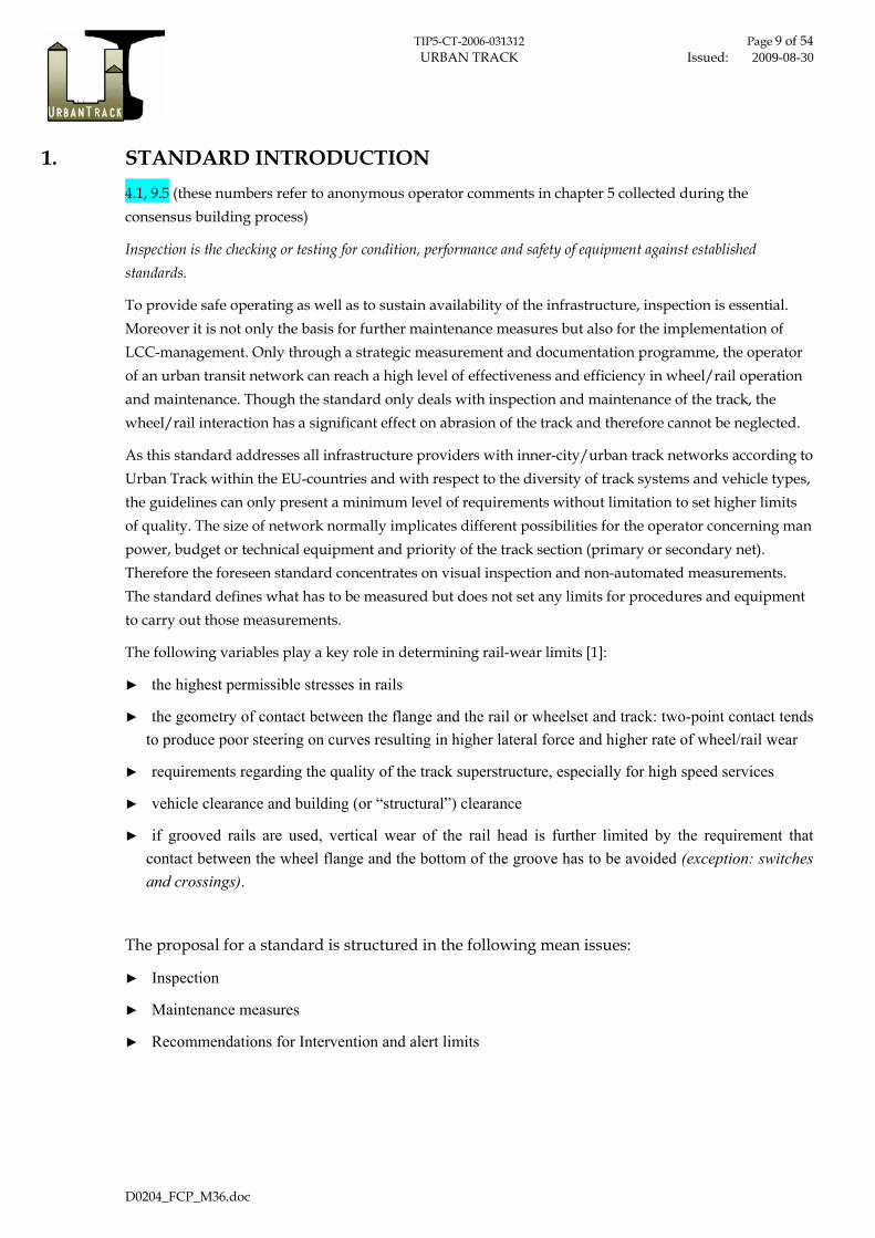
Figure 7 Vertical and lateral wear of the rail head
Limit of lateral wear is reached when the wear gets to the lowest point of the rail head (see Figure 7). Rails with deformation and crushing of the rail head have to be removed when the track gauge goes below the minimum level and the required track gauge cannot be set up through maintenance measures.
For grooved rails the limit of vertical wear is set through the difference of the groove depth for new rails and flange height for new wheels. As bumping of the flange should be avoided (except in the field of flat grooves) because of the reduced breaking effect, vertical rail wear has to be limited such that the groove depth is higher than the flange height of a new wheel. Depth of flat grooves should be 13 mm at its minimum.
Lateral wear of grooved rails is limited by the requirements regarding track gauge (see 2.1.1.1) and to safety criteria in terms of individual traffic.
The groove width W is limited in case of embedded track as follows:
► Wmax ≤ 45 mm (straight track)
► Wmax ≤ 60 mm (curved track)
TIP5-CT-2006-031312 Page 19 of 54 URBAN TRACK Issued: 2009-08-30
D0204_FCP_M36.doc
Figure 8 Grooved rail with vertical and lateral wear and deformation of the rail head
2.1.2.2. Corrugation
14., 17.1
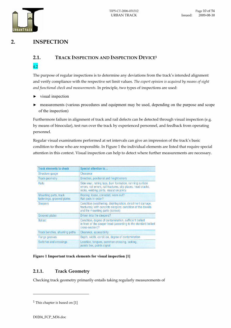
Vertical irregularities of the rail profile with wavelength smaller than 1 m that induce commensurately higher frequencies are embraced by the term “corrugation”. They are important with regard to dynamic behaviour of the track and therefore they also play a major role in determining the noise [4] [1]. Corrugation can be differentiated from vertical irregularities at relatively long wavelengths (typically greater than 3 m) that excite correspondingly low frequencies. They are associated with formation of the track; furthermore they are important with regard to dynamic behaviour of the vehicle (see 2.1.1.3).
Wavelengths [m] Frequency [Hz] Type of defect Treatmentirregularities in rail
0.03 - 0.10 740 - 220 short wavelength corrugation0.10 - 1.00 220 - 22 .0 long wavelength rail corrugation1.00 - 3.00 22.0 - 7.40 long waves and rolling defects
irregularities in formation3.00 - 25.0 7.40 - 0.89 cant, level alignment, twist, gauge tamping stone-blowing25.0 - 70.0 0.89 - 0.32 alignment design 70.0 - infinity 0.32 - 0.00 design geometry design
grinding; straighten welds
frequency range is that excited by a vehicle travelling at 80 km/h
Figure 9 Classification of typical irregularities in track [4]
Corrugation has to be seen as the result from several different dynamic mechanisms in vehicle/track interaction. Less variety in vehicle type and train speeds intensifies problems like corrugation or rolling contact fatigue, which occur at the wheel/rail interface.
To avoid corrugation, grinding is an essential maintenance tool to extend rail life even though it also consumes rail life.
Skidding pattern shows similar damage symptoms as corrugation and has to be corrected by grinding. Skidding pattern mainly arise in curves with small radii.

TIP5-CT-2006-031312 Page 20 of 54 URBAN TRACK Issued: 2009-08-30
D0204_FCP_M36.doc
2.1.2.3. Engine burn
Engine burn caused by skidding can’t be avoided through infrastructure-sided measures. If they occur the damaged rail has to be replaced.
2.1.2.4. Cracks, fractures, head checks
14., 17.1
Track guidance can only be safe if rail heads are uniformly undamaged. There can be various reasons for rail fractures, such as faulty material used in their manufacture (rather exceptional nowadays), mistakes made during joint and build-up welding (one of the most common reasons), and also material fatigue. Incorrect heat treatment or unsuitable materials in conjunction with build-up welding can cause cracks which can lead to rail fractures later on. Head checks, fine cracks in flanges that result in nicks, normally only occur in domains of railway track that are subjected to high axle loads.
In addition holes in the web of the rail are a common reason for rail breakage as well. In general a hole in the web of the rail has to be drilled (punching is only allowed under prefabricated conditions in the plant).
Cracks, fractures and head checks have to be located through periodic visual inspection by qualified personnel and/or by feedback of drivers or electrical conductivity (signal).
2.1.2.5. Relevant components to be checked
Rail Fastening
4.5, 10.5, 17.1
Rail fastenings have to be checked for condition and effectiveness and have to be tightened if necessary.
Anchor, safety cap
Condition and effectiveness of anchors and safety caps has to be checked.
Guide bar, check rail
Guide bars and check rails have to be checked for proper operation by visual inspection and inspection of the fastenings.
Rail joint
14.

TIP5-CT-2006-031312 Page 21 of 54 URBAN TRACK Issued: 2009-08-30
D0204_FCP_M36.doc
► Rail joint with fish plate: Mechanical properties of rail joint with fish plates have to be checked for proper operation under load. Electric conductivity has to be tested.
► Welded rail joint: The weld seam has to be checked for proper operation by ultrasonic flow measuring method. Electric conductivity has to be tested.
► Insulated rail joint: A visual inspection must ensure that the rolling laps at both sides of the insulated rail joint, do not contact. Bonding and bolting has to be checked for proper operation by visual inspection.
Dilatation device
Dilatation devices (overlap of rail, feathered joint) have to be checked for proper operation. Standard operating procedures and test specifications e.g. given by the manufacturer have to be considered.
Lubrication
14.
Lubrication has to be checked for proper operation by visual inspection.
Buffer stop
Buffer stops have to be checked for proper operation by visual inspection.
Turnouts and crossings
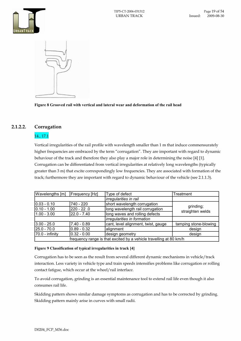
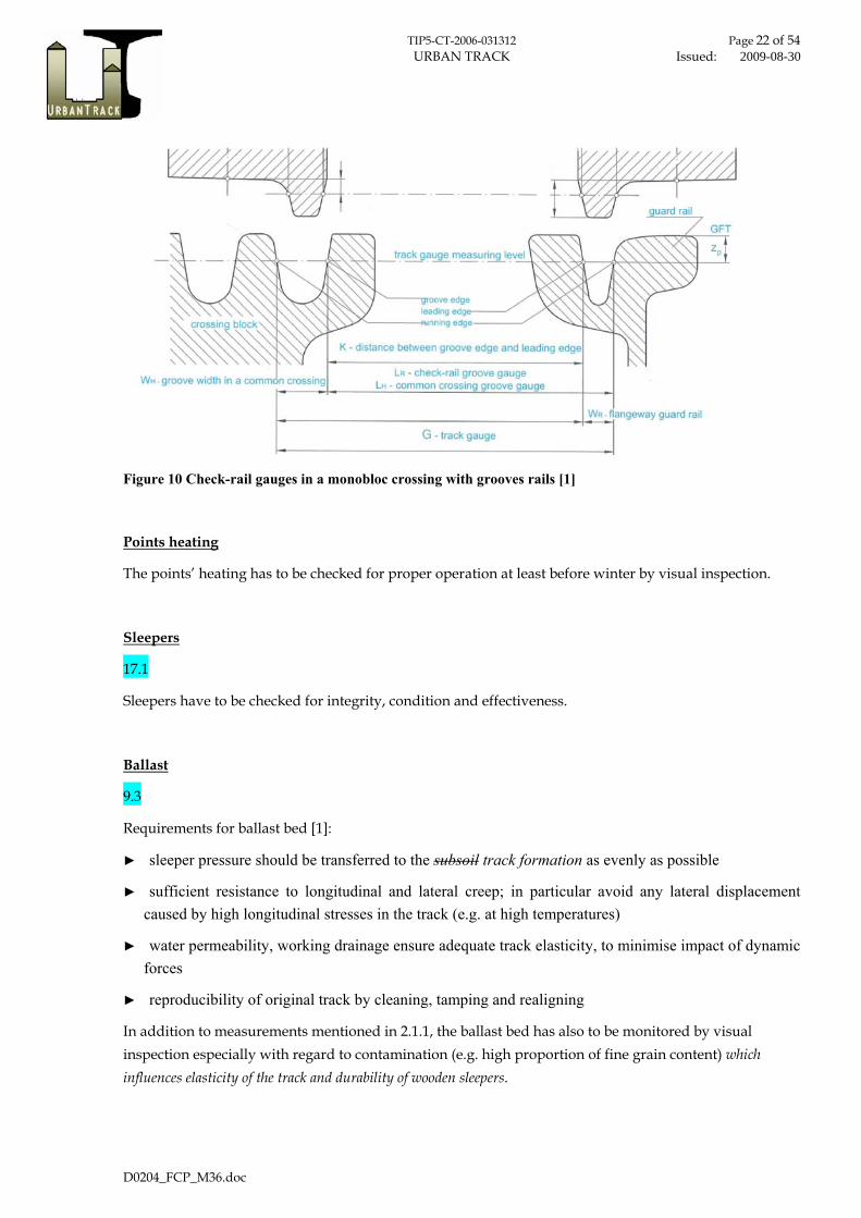
As a minimum the following geometric values have to be measured:
► Gauge, guard check gauge, guard face gauge
► groove width
► check-rail groove gauge, crossing groove gauge
► common crossing groove gauge
► position of switch blade against stock rail
► gap between adjacent switch blade and stock rail
► gap between distant switch blade and stock rail
In addition to that point mechanisms as well as all moving parts have to check for proper operation (function, fast moving, clean). Tables of geometric limit values have to be set according to dimensions of the wheel-set of the operating vehicles.
TIP5-CT-2006-031312 Page 22 of 54 URBAN TRACK Issued: 2009-08-30
D0204_FCP_M36.doc
Figure 10 Check-rail gauges in a monobloc crossing with grooves rails [1]
Points heating
The points’ heating has to be checked for proper operation at least before winter by visual inspection.
Sleepers
17.1
Sleepers have to be checked for integrity, condition and effectiveness.
Ballast
9.3
Requirements for ballast bed [1]:
► sleeper pressure should be transferred to the subsoil track formation as evenly as possible
► sufficient resistance to longitudinal and lateral creep; in particular avoid any lateral displacement caused by high longitudinal stresses in the track (e.g. at high temperatures)
► water permeability, working drainage ensure adequate track elasticity, to minimise impact of dynamic forces
► reproducibility of original track by cleaning, tamping and realigning
In addition to measurements mentioned in 2.1.1, the ballast bed has also to be monitored by visual inspection especially with regard to contamination (e.g. high proportion of fine grain content) which influences elasticity of the track and durability of wooden sleepers.

TIP5-CT-2006-031312 Page 23 of 54 URBAN TRACK Issued: 2009-08-30
D0204_FCP_M36.doc
Condition of ballast has to be located through periodic visual inspection by qualified personnel and/or by feedback of drivers.
Pavement
The pavement, located between the slabs in the track area, the rails and the road surface, serves to enable pedestrians or vehicles to walk or ride over tracks laid in street spaces [1].
Condition of covering has to be located through periodic visual inspection by qualified personnel and/or by feedback of drivers.
Asphalt
Mastic asphalt can be installed in track systems quickly and easily.
Symptoms of damage:
► cracks –single or netlike
► nicks and joints
► depressions and bulges
► lane grooves
► asset erosion
► lack of adhesion
Removal and relaying of the asphalt is necessary for repair.
Stone pavement
Stone pavement work assumes skilled workers and is time consuming. For aesthetic and design reasons paving can be requested.
Symptoms of damage:
► tilted or protruding paving stones
► depressions
Concrete slabs
Concrete slab installation needs large equipment and is expensive; however slabs can be returned to their position as long as they are intact. Otherwise, they must be renewed or replaced by asphalt.
Symptoms of damage:
► tilting slabs
► sink, shift or breakage of slabs
► loose slabs because of defective bedding
► protruding steel edges

TIP5-CT-2006-031312 Page 24 of 54 URBAN TRACK Issued: 2009-08-30
D0204_FCP_M36.doc
Joint sealant
Requirements:
prevent water and dirt from penetrating the joints between rails and road
► allow minimal mobility of the rails relative to the road surface without damaging the cover
► renewable
The use of joint sealant significantly extends the lifetime of track systems, but the joint material ages because of UV radiation causing hardening. In addition, the compound’s consistency is changed by pollutant input, and the joint material can be completely destroyed by mechanical or thermal (build-up welding) effects.
The most common types of rail-road joint sealant are
► bituminous joint sealant
► joint sealant based on artificial resin
Condition of joint sealant has to be located through periodic visual inspection by qualified personnel.
Contact line, conductor rail (horizontal and vertical position)
The horizontal and vertical position of contact line or conductor rail has to be checked and verified against track alignment (horizontal and vertical).
Structure gauge
9.6, 17.1
The structure gauge has to be kept free at all times. This has to be ensured verified by visual inspection and the feedback of operating personnel.
Dewatering
The effectiveness of the dewatering equipment has to be checked by visual inspection.
2.2. INSPECTION SCHEDULE
The following recommendations have to be seen as minimum requirements.

TIP5-CT-2006-031312 Page 25 of 54 URBAN TRACK Issued: 2009-08-30
D0204_FCP_M36.doc
Clearance of structure gauge annually / after indicationTrack geometry annually / after indicationRails annually / after indicationMounting parts, track fastening, grooved plates annually / after indicationsleepers annually / after indicationballast annually / after indicationtrack benches, shunting paths annually / after indicationflange grooves annually / after indicationSwitches and crossings quarterly / after indication
Track Inspection - Schedule
Table 1 Minimum requirements visual inspection

TIP5-CT-2006-031312 Page 26 of 54 URBAN TRACK Issued: 2009-08-30
D0204_FCP_M36.doc
3. MAINTENANCE MEASURES 10.2, 10.3, 10.4, 10.5
3.1. MAINTENANCE PHILOSOPIES
In principal maintenance can be classified by:
► corrective maintenance – CM
► condition based maintenance – CBM
► preventive maintenance – PM
Figure 11 Definition of Maintenance
Therefore maintenance includes:
► Servicing
► Inspection
► Corrective maintenance
► Refurbishment (improvement)
Maintenance
Preventive Maintenance Corrective Maintenance
Condition based
PredeterminedMaintenance
Scheduled, continous
Scheduled Deferred Immediate

TIP5-CT-2006-031312 Page 27 of 54 URBAN TRACK Issued: 2009-08-30
D0204_FCP_M36.doc
3.2. SERVICING
Servicing involves measures designed to delay deterioration of the existing wear margin, such as rail and switch lubrication and track, switch and groove cleaning.
3.2.1. Lubrication
4.6, 14.
The purpose of lubrication is to reduce wheel and rail wear on curved track; in addition it helps to reduce noise especially by avoiding or curbing curve squeal.
As a disadvantage the lengthening of the breaking distance as a result of the reduction of wheel/rail friction has to be mentioned. The amount of lubricant therefore must be determined depending on the weather and based on local parameters.
Rail lubricators must be located at the start of the transition curve. The wheel can take the lubricant with it, thus lubricating the entire curve. If installation at the onset of the curve is not desired, a lubrication strip can be installed on straight sections of track before the transition curve.
Optimising the location of lubrication can result in a single device lubricating several successive curves.
Lubrication techniques in practice are:
► Application of lubricant by hand
► Spreading by a lubricating vehicle
► Spreading by a stationary lubricator
► Lubricating by flange lubrication
For environmental reasons, all lubricants used must be biodegradable. Those commonly used are:
► Water
► Liquid grease
► Lubricating grease
► Lubricants with solid additives
3.2.2. Surface cleaning
4.7
Over time, dirt and waste collect in the track systems as a result of train operation (brake dust, brake sand), public behaviour or natural phenomena (e.g. fallen leaves). Track systems that are visible to the

TIP5-CT-2006-031312 Page 28 of 54 URBAN TRACK Issued: 2009-08-30
D0204_FCP_M36.doc
public should be regularly cleaned, to maintain a clean, orderly and costumer-friendly appearance. However, there are technical and economic and legal aspect and safety considerations for surface cleaning.
3.2.3. Cleaning ballast
The ballast bed requires cleaning if it is full of fine, abraded particles and outside dirt creating a bed with insufficient elasticity and bearing capacity. For ballast cleaning stationary or mobile screening units or, most simply, manually ballast forks can be used.
The use of mobile ballast cleaning units is limited to sections of railway track. In general they cannot be used in metros and tramways because of space restrictions. Consequently cleaning ballast by using forks is still a common practice today on small construction sites in metro tunnels. It has to be distinguished between cleaning the surface only and cleaning hole the ballast.
3.2.4. Cleaning rail grooves
Deposits of “road dirt”, brake sand, leaves, and (in cold seasons) sand accumulate in the grooved rails of embedded tracks. Larger deposits hamper the free passage of wheel flanges and can become a derailment hazard. They also prevent grooves from draining efficiently. In addition, clean rails are a prerequisite for the smooth functioning of certain track release equipment used to control points and signals. Electrical isolation due to filled grooves can cause serious safety aspects and signal problems.
3.2.5. Cleaning switches
Smooth rail operations depend on the availability and the proper functioning of switches. Switches’ tongues must be able to move unimpeded and without great effort into their planned final positions. To ensure this the respective side plates must be clean and the space through which the tongue travels must be unimpeded.
Keeping moving parts clean is essential for avoiding unnecessary wear.
Due to cumulating road dirt and their enclosed design, cleaning switches embedded in road surfaces is required more frequently compared to switches for vignole rails.
3.2.6. Cleaning track drainage systems
10.1
This includes rinsing rail drainage facilities and cleaning any drainage shafts. On tramways, this needs to be done at least in spring in order to remove road grit, and in autumn for removal of leaves, using high-pressure cleaning and suction vehicles.

TIP5-CT-2006-031312 Page 29 of 54 URBAN TRACK Issued: 2009-08-30
D0204_FCP_M36.doc
3.2.7. Care and control of vegetation
► Trimming back tree and bush growth
► Suppressing uncontrolled plant growth on tracks
► Caring for green tracks
3.2.8. Snow clearing and ice removal in winter
The plan for snow clearing and ice removal must guarantee the fulfilment of the operator’s duty to ensure traffic safety and the flow of services.
This plan has to take into account the geographical circumstances the operator has to deal with.
3.3. CORRECTIVE MAINTENANCE
3.3.1. Grinding
17.1
There are three key reasons for rail grinding:
► Removal and management of corrugation
► Removal and management of rolling contact fatigue
► Restoration of rail profile to ensure desired rail /wheel contact for optimal vehicle curving behaviour and ride quality (re-profiling)
In addition grinding of new rails is suggested to remove construction dirt and the rolling skin.
3.3.2. Rail alignment
9.6, 17.1
Levelling
Tamping
3.3.3. Maintenance of track covering
Asphalt
Paving
Concrete slabs
Repair of joint sealant

TIP5-CT-2006-031312 Page 30 of 54 URBAN TRACK Issued: 2009-08-30
D0204_FCP_M36.doc
3.3.4. Build-up welding
► Recreate the original geometry of a rail or improve its geometry
► Cost-effective maintenance (with grooved rail) involves the replacement of material loss due to wear with harder equivalents to extend the lifetime of the rails (possible for several times)
Through build-up welding a wide variety of repairs can be carried out. The most important are:
► Repairs to the running surface
o Anti-corrugation welds
o Anti-squeal welds
► Repair to curved tracks: wear to both the running and leading edges of curved rails can be compensated by side build up welding.
► Repair of points
o Switch tongues
o Frog points
o Flat grooves including ramps
o Guard rails

TIP5-CT-2006-031312 Page 31 of 54 URBAN TRACK Issued: 2009-08-30
D0204_FCP_M36.doc
4. RECOMMENDATIONS FOR INTERVENTION AND ALERT LIMITS 9.1, 9.2, 9.3, 9.6, 10.2, 10.3, 10.4, 17.1, 17.2
4.1. SCOPE
This draft of a standard attempts to find common safety limits for European urban transit networks following the development of high speed and conventional standard-gauge railways and broad gauge railways (prEN 13848-5:2005).
Intervention and alert limits can be seen as recommendations; how the operator or infrastructure manager deals with track quality levels before reaching safety limits will depend on their individual maintenance strategy and on the passenger’s claim.
4.2. DEFINITION OF CATEGORIES
17.2
The following categories are defined by the necessity and urgency of maintenance measures in interconnection with the inspection results. In the same time the different maintenance philosophies are able to be included (Figure 11).
Safety Refers to the value which, if exceeded, requires taking immediate measures which could lead to lowering the maximum speed of trains or closing the line, until the defect has been corrected.
Intervention Limit (Cost-effectiveness)
Refers to the value which, if exceeded, requires corrective maintenance in order that the safety limit shall not be reached before the next inspection.
Alert Limit (Comfort / Environment)
Refers to the value which, if exceeded, requires that track geometry condition is analysed and considered in the regularly planned maintenance operations.
Table 2 Classification of maintenance categories

TIP5-CT-2006-031312 Page 32 of 54 URBAN TRACK Issued: 2009-08-30
D0204_FCP_M36.doc
4.3. INTERVENTION AND ALERT LIMITS
4.8, 9.1, 9.2, 9.3, 9.6, 10.2, 10.3, 10.4, 17.1, 17.2
4.3.1. Track gauge
Minimum gaugesafety G ≤ Gnom - 5 mmcost-effectiveness (Gnom - 5 mm) ≤ G ≤ (Gnom - 3 mm)comfort/environment (Gnom - 3 mm) ≤ G ≤ Gnom
Maximum gaugesafety G ≥ Gnom + 30 mmcost-effectiveness (Gnom + 30 mm) ≥ G ≥ (Gnom + 22 mm)comfort/environment (Gnom + 22 mm) ≥ G ≥ Gnom
Track gauge (G)
4.3.2. Horizontal alignment
safety 22 mm (mean to peak value)cost-effectiveness 14 - 16 mm (mean to peak value)comfort/environment 12 - 14 mm (mean to peak value)
Horizontal alignment (wavelength range: 3 m < λ ≤ 25 m)
4.3.3. Longitudinal Level
safety 20 - 29 mm (mean to peak value)cost-effectiveness 16 - 20 mm (mean to peak value)comfort/environment 12 - 18 mm (mean to peak value)
Longitudinal level (wavelength range: 3 m < λ ≤ 25 m)
4.3.4. Cross level
safety 16 mm (mean to peak value)cost-effectiveness 12 - 14 mm (mean to peak value)comfort/environment 10 - 13 mm (mean to peak value)
Cross level
4.3.5. Twist
The limit value of twist has to be defined in accordance to stiffness and constructional characteristics of the running gear.

TIP5-CT-2006-031312 Page 33 of 54 URBAN TRACK Issued: 2009-08-30
D0204_FCP_M36.doc
4.3.6. Grooves
Depth of flat grooves should be 13 mm at its minimum.
The groove width W is limited in case of embedded track as follows:
► Wmax ≤ 45 mm (straight track)
► Wmax ≤ 60 mm (curved track)
4.4. MAINTENANCE MEASURES – REVIEW
4.9, 9.2, 9.3, 9.4, 10.1, 10.2, 10.3, 10.4, 10.5, 14.
Element Failure / Reason Measure How often / indication Classification *)
rail curve of small radius lubrication - fixed station continuous comfort/environment
wheel squeal lubrication - fixed station continuous comfort/environment
corrugated rail, burr formation
grinding, deburring of rail and rail joint
after visual inspection; exceeding limits for track gauge
cost-effectiveness
rail breakage applying joint bars; speed reduction or service break if necessary until rail breakage can be repaired
after visual inspection; feedback from driver
safety
track gauge gauge narrowing grinding, deburring of rail and rail joint reaching safety limit safety
reaching intervention limit
cost-effectiveness
reaching alert limit comfort/environment
gauge widening build-up welding or replacing rail reaching safety limit safety
reaching intervention limit
cost-effectiveness
reaching alert limit comfort/environment
turnout preventive maintenance mobile lubrication after cleaning cost-effectiveness
preventive maintenance
cleaning and lubrication of point mechanism
before and after winter
cost-effectiveness
turnout & crossing corrugated rail, burr
formation grinding, deburring of rail
after visual inspection; feedback from driver
cost-effectiveness
ballast bed
sufficient resistance to longitudinal and lateral creep is not guaranteed
tamping
after visual inspection
cost-effectiveness
contamination
screening of ballast
after visual inspection and/or feedback from driver
cost-effectiveness
sleepers breakage replace after visual inspection safety
drainage failure cleaning, renewal in case of failure safety

TIP5-CT-2006-031312 Page 34 of 54 URBAN TRACK Issued: 2009-08-30
D0204_FCP_M36.doc
planting vegetation on the tracks
mowing, weed-killing
after visual inspection
cost-effectiveness
pavement -asphalt
► cracks -single or netlike ► nicks and joints ► depressions and bulges ► lane grooves ► asset erosion ► lack of adhesion
removal and relaying
after visual inspection
cost-effectiveness
pavement - paving
► tilted or protruding paving stones ► depressions
removal and relaying or replacement by asphalt
after visual inspection
cost-effectiveness
pavement – concrete slabs
► tilting slabs ► sink, shift or brake of slabs ► loose slabs because of defect bedding ► protruding steel edges
removal and relaying or temporary replacement by asphalt
after visual inspection
cost-effectiveness
Table 3 Maintenance measures

TIP5-CT-2006-031312 Page 35 of 54 URBAN TRACK Issued: 2009-08-30
D0204_FCP_M36.doc
5. OPERATOR REMARKS All operator remarks during the consensus bulding process were collected in an anonymous way and are listed below. This should allow later on to understand limitation of this work and support eventual further standardisation efforts in the future.
Operator 1
Operator 1 has supported the creation of the proposal. The comprehensive metro and tramway in-house standards were provided as helpful background.
Nevertheless the staff of Operator 1 is of opinion that one-sided definition of limit values for urban track inspection and maintenance is not currently purposeful because of the current rapid change of knowledge base in defining the rules and standards. Definition of limit values is based on satisfaction of few demands: safety, speed/comfort and economy. The present research has shown that one-sided limit values could be meaningful only if they would be given for particular track in particular urban conditions. Integral limit values could be used perhaps for a security management system as the upper limitation for excessive limit. Therefore determination of general rules and limit values presents a long, comprehensive iterative process, which will take a long time after which it should conduce to one comprehensive result.
Considering what was mentioned above, there is no interest of Operator 1 in defining the integral Standard for urban tracks at the moment but they are interested to participate in the future standardisation process and give their contribution in domain of creating mechanisms and criteria for the future European Standard.
Operator 2
The proposal of the standard for visual inspection and maintenance created in Subproject 2.2.1 was submitted to Tram Company preparatory to the meeting. It has been read and some remarks came up in the discussion.
The relevant operator staff and experts for inspection and maintenance are not used to deal with standards in English language. So we could not get any statement about the proposal but a useful table of Operator 2 was submitted.

TIP5-CT-2006-031312 Page 36 of 54 URBAN TRACK Issued: 2009-08-30
D0204_FCP_M36.doc
Operator 4
4.1 Chapter 1 –Introduction- the definitions presented should be completed, such as: servicing and maintenance, inspection, reconditioning, prevention.
4.2 Figure 1” Important track elements for visual inspection”, it should be mentioned that wooden sleepers could also have anchor fittings and that this must be incorporated in the inspection.
4.3 Chapter 2.1.1.3 -Longitudinal level- there is the following explanation:
“The height of rail, in combination with the respective longitudinal height, provides an early indication of any emerging weak points in the substructure and also allows conclusions to be determined about the change in quality of welded joints.” On this position there is a lack of definition „height of rail“ or the “Delta height of rail”.
The recommendation is, to add a picture to complete the definition. In Germany there are alert limits, which can be used as a reference.

TIP5-CT-2006-031312 Page 37 of 54 URBAN TRACK Issued: 2009-08-30
D0204_FCP_M36.doc
4.4 Chapter 2.1.2.1 -Profile changes- there is an explanation for grooved rails. There you can find the passage that the limit of vertical wear is set through the difference of the groove depth for new rails and flange height for wheels. The operator gave the advice that depending on the network, there is also "growing" flanges of wheel (e.g. networks with little or no flat grooves). A limit value must be defined for this case.
4.5 Chapter 2.1.2.5 -Relevant components to be checked- this operators advises to add the following passage:
“Rail fastenings have to be checked for condition and effectiveness and have to be tightened if necessary”. Depending on the resilience, there are limitations when tightening.”
4.6 Chapter 3.2.1 -Lubrication-
Moreover, the lubrication of the head of the rail due to problems of braking effects is often not allowed. In this context, lubrication of the wheel flange of the vehicle is needed. The lubrication of turn out elements without affecting the wheel-rail contact (e.g. slide and poles etc.) is very important and must be completed.
4.7 Chapter 3.2.2 -Surface cleaning- this section needs to be completed with:
Overriding of the wheel flange on the dirt is comparable to the overriding of the wheel flange of grooved rails. This means danger of isolation and that the vehicle can be set under electricity! The braking effects can change when the wheel rims lose contact with the driving surface.
4.8 In the chapter 4.3 -Intervention and alert limits- the Operator recommends for the Track gauge in the category safety:
G ≤ Gnom – 3 mm instead of G ≤ Gnom – 5 mm.
4.9 Chapter 4.4 -Maintenance measures- in Table 3 at point wheel squeal the following passages can be added:
Speed reduction as a measure against the squeal of the wheels is proposed as a complement.
Operator 6
The proposal of European standard for inspection and maintenance of urban track was submitted and sent to Operator 6.
After reading and technical expertise of the relevant authority in the Operator 6 transport company, the Operator is of opinion that the proposal is a good guideline for urban railways. It comprises all aspects such as geometry, construction, inspection, preventive and corrective maintenance as well as it considers

TIP5-CT-2006-031312 Page 38 of 54 URBAN TRACK Issued: 2009-08-30
D0204_FCP_M36.doc
measures that should be implemented in inspection and maintenance policy. The Operator 6 will participate and support the future work in creating the Standard of urban track systems in European countries.
Operator 7
The proposal of the standard for visual inspection and maintenance created in Subproject 2.2.1 of Urban Track project was submitted to Operator 7 preparatory to the meeting. It has been read and some remarks came up in the discussion.
In general Operator 7 is using the EN 13848 modified to the metro conditions of the served town. There is an existing complicated network of regulations for inspection and maintenance. The proposal of the standard is not completely convenient to the track conditions of the served town (e.g. rubber tyres). Therefore Operator 7 is not highly interested in the standard work of SP 2.2.1.
Operator 9
The Operator 9 has analysed the proposal in detail and has given some important remarks related to intervention and alert limits.
Operator 9 applies tighter limit values than it is suggested in the document “Proposal of European Standard for track inspection and maintenance”. They enclosed the table with current implemented tolerances but they plan to tighten them more.
Operator 9 is a young metro system and the company has not yet enough experiences with its operations. The track system is a new one and it will take a time to find out whether the maintenance and inspection policy method is the right one.
The metro company uses tighter tolerances than the proposed values within this this proposal of standard, therefore this company is not really ready for the implementation of proposal in their maintenance and inspection policy. The metro staff of Company 1, who is in charge of maintenance activities for the Operator 9, enclosed the table with proposed limit values for the operating system in the served town. The Operator 9 has opinion that the limits suggested in our proposal are not restrictive enough. They should be tighter.

TIP5-CT-2006-031312 Page 39 of 54 URBAN TRACK Issued: 2009-08-30
D0204_FCP_M36.doc
The tolerances should be given for both ballast and concrete track systems with values for each system separately according to different behavior of track systems.
Connection between speed and intervention and alert limits should be given.
Some aspects should be analysed more in-depth and approved such as:
9.1 Intervention and alert limits should be more restricitve than the proposed limits in Standard,
9.2 To specify to which speed the proposal is based on, 9.3 Tolerances should be given for concrete and ballast track separately, 9.4 Treatment of concrete track after defects occur, 9.5 Some terminology within the proposal needs to be clarified (tolerance, uncertainty, importance of the parameters in the definition of the tolerances)
9.6 Limit values proposed by Company 1:
* These values are not approved by Operator 9
Operator 10
Concrete Ballast
Comfort/ Environment
(AL)
Cost-effectiveness
(IL)
Safety
(IAL)
Comfort/ Environment
(AL)
Cost-effectiveness
(IL)
Safety
(IAL)
Gauge (mm) +5/-5 +7/-7 +15/-10 +5/-5 +7/-7 +15/-10
Cross Level (mm) +4/-4 +6/-6 +15/-15 +4/-10 +6/-15 +20/-25
Twist (mm/m) chord 3m +5/-5 +7/-7 +14/-14 +5/-5 +7/-7 +14/-14
Horizontal Alignment (mm) +4/-4 +6/-6 +14/-14 +4/-10 +6/-15 +20/-25
Longitudinal Level (mm) for wavelength of 25m +5/-5 +7/-7 +16/-16 +5/-5 +7/-7 +16/-16
Groove (mm) +5/-5 +7/-7 +10/-10 ---- ---- ----

TIP5-CT-2006-031312 Page 40 of 54 URBAN TRACK Issued: 2009-08-30
D0204_FCP_M36.doc
The proposal of the standard for visual inspection and maintenance created in Subproject 2.2.1 of Urban Track project was submitted to Operator 10 preparatory to the meeting. It has been read and some remarks came up in the discussion.
There was the wish for new geometric measurement methods and devices for the inspection of levelling and horizontal alignment. The absolute coordinates of the track are not of such importance and are mostly unknown. Especially at the old tracks the project coordinates are unknown too. So it is senseless to compare existing and projected coordinates. Relative measurements should be preferred in urban tracks with correlation of lateral and vertical derivations (limits).
Some aspects should be emphasised:
10.1 Drainage inspection 10.2 How to measure 10.3 Quality index 10.4 Criteria to verify the quality of track works 10.5 Inspection within maintenance (direct fixation of rail profile)
Operator 11
The proposal of the standard for visual inspection and maintenance created in Subproject 2.2.1 of Urban Track project was not finished at the time of the Operator 11 visit. The proposal was delivered to operator afterwards.
Old urban tracks of the served town are mainly ballasted track while the new ones are constructed as a slab track. Noise and vibration problems led to the construction of floating slab track in tunnel sections that are mainly constructed on sand. The limiting values for comfort and safety, as well as a track quality index as a function of some track parameters, have to be defined.
Operator 11 is very interested to participate in the future work on European Standard.

TIP5-CT-2006-031312 Page 41 of 54 URBAN TRACK Issued: 2009-08-30
D0204_FCP_M36.doc
Operator 14
Discussions with Operator 14 were very useful in relation with detailed description of types of track systems, maintenance policy and problems occurring in operating system. The operator has made a great effort and has provided us with lot of information about characteristics of the metro system, as well as its failures and defects.
Within the visit to Operator 14 the night inspection was done. The new lubrication emulsion is presented and its implementation was demonstrated. The new lubricant has 90% water and provides good rail characteristics. It has been spread out by a stationary lubricator. Measures show better results and less wear on curved tracks after implementing the new lubricant means. This helps to reduce noise as well.
Regarding the “Proposal of European Standard for Track Inspection and Maintenance” the operator agreed with its content. The metro staff of Operator 14 thinks that special attention should be paid to the implementation of lubricant method. They believe that lubricant emulsion could be good not only for the reduction of wear in the wheel/rail contact but also for the reduction of corrugation - especially on curved tracks.
The second issue that should be more thoroughly explored is ultrasonic inspection for welded rail joints as a measure for reducing a risk of rail cracks and fractures.
The metro staff of Operator 14 will support the future work on Standard but at the moment their interest is focused on standard impact on maintenance cost reduction.
Operator 17
Staff of Operator 17 was good prepared for the interview and they presented a lot of information about operating tramway and metro track systems with the description of cross sections and its characteristics. Weakness of the old track system and advantages of the new one are described in detailed with a lot of illustrations and explanations.
The Operator 17 applies the limit values in inspection and maintenance policy, as it is shown in the Table below.

TIP5-CT-2006-031312 Page 42 of 54 URBAN TRACK Issued: 2009-08-30
D0204_FCP_M36.doc
17.1 Limit values used in maintenance and inspection policy in the served town: Limit values (in case of V=50 km/h)
Deviation from nominal value in mm if
the category is: Denomination
A B C
Note
Gradual widening/narrowing of gauge per meter at curves
2 4 6 At speed of v<20 km/h double value is allowed
Difference of subsequent arch pitches in the centre
of chord
±4% ±7% ±10% Inspection has to be carried out in curves continuously at half of chord length distances
Superelevation in curves ±4 ±10 ±15
Cross subsidence 2 8 15
Plane distortion 1:400 1:300 1:150
Values must be kept in easement curves, too, and at the ends of superelevations measured on base length of min. 2,0 m
Level defects in the middle of a section of 4 m between two points
3 10 20 The values include rail head inclinations too
Rail head abrasion
Vertical abrasion Grooved rails
48 system rails
34 system rails
Lateral abrasion
Grooved rails
48 system rails
34 system rails
0
0
0
0
0
0
18
20
13
10
17
15
22
25
18
15
25
20
In case of grooved rails abrasion of the rail nozzle cannot be more than 2 mm from the outer edge, possibility of inclination of rail nozzle cannot develop due to vertical abrasion. Spacers of tracks cannot be reached by flanges
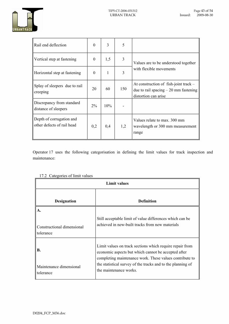
TIP5-CT-2006-031312 Page 43 of 54 URBAN TRACK Issued: 2009-08-30
D0204_FCP_M36.doc
Rail end deflection 0 3 5
Vertical step at fastening 0 1,5 3
Horizontal step at fastening 0 1 3
Values are to be understood together with flexible movements
Splay of sleepers due to rail creeping
20 60 150 At construction of fish-joint track – due to rail spacing – 20 mm fastening distortion can arise
Discrepancy from standard distance of sleepers
2% 10% -
Depth of corrugation and other defects of rail head
0,2 0,4 1,2 Values relate to max. 300 mm wavelength or 300 mm measurement range
Operator 17 uses the following categorisation in defining the limit values for track inspection and maintenance:
17.2 Categories of limit values
Limit values
Designation
Definition
A.
Constructional dimensional tolerance
Still acceptable limit of value differences which can be achieved in new-built tracks from new materials
B.
Maintenance dimensional tolerance
Limit values on track sections which require repair from economic aspects but which cannot be accepted after completing maintenance work. These values contribute to the statistical survey of the tracks and to the planning of the maintenance works.

TIP5-CT-2006-031312 Page 44 of 54 URBAN TRACK Issued: 2009-08-30
D0204_FCP_M36.doc
C.
Limit values requiring immediate actions
Immediate actions can be the following:
— regular inspection with great caution; — speed limitation if immediate measures cannot be
taken; — track closure in case of risk of derailment
Operator 18
Operator 18 has made a lot of efforts to submit information related to tram track system and it’s operating. Documentation with characteristics of old and new track systems, its deficiencies, typical cross sections as well as actions undertaken in maintenance policy have been sent. The main part of tram lines in the served town is track with segregated right of way. According to problems generated by noise and vibration, since 2000 the new strategy and method are implemented in operating the rail system. To reduce the noise effects they use an anchored system adopted from Germany.
The Operator 18 is highly interested to participate in the future work in creating the European Standard.
Operator 19
The Operator 19 is aware of importance of setting the higher quality limit in inspection and maintenance of urban track networks within the European countries. Adoption and implementation of standards are stipulated by size of network i.e. technical equipment, budget, man power and priority of the track section.
The Operator 19 has made an effort to provide us with useful information about operating the track systems and maintenance and inspection policy, especially about measurements of horizontal alignment.
The Ministry for Transport has standardized its own regulations for design and operating tram and metro systems in the country. The infrastructure provider is not involved in the creation of national standards and has to work in accordance with the policy of Ministry for Transport. Nevertheless there is readiness for collaboration within the standardisation process.

TIP5-CT-2006-031312 Page 45 of 54 URBAN TRACK Issued: 2009-08-30
D0204_FCP_M36.doc
Operator 20
Similar to Operator 19 the staff of Operator 20 uses the national standards for tram operating system. Therefore their collaboration in project was done in domain of information about types of track systems as well as in inspection and maintenance policy carried out within the company.
Operator 20 works according to standards and rules set by Ministry for Transport. The Operator 20 is ready and interested to collaborate in standardisation of maintenance and inspection policy for European track systems. They are of opinion that proposal for EU Standard could be useful for operators and they will support the future work on it.
No remarks were presented from the rest of the operators (Operators n°3, 5, 8, 12, 13, 15 and 16).

TIP5-CT-2006-031312 Page 46 of 54 URBAN TRACK Issued: 2009-08-30
D0204_FCP_M36.doc
6. LCC GENERAL DESCRIPTION This report describes the approach of the LCC-calculation for the SP 2.2.1 “Visual inspection and maintenance”.
This case compares two maintenance variants based on the maintenance categories (Table 4) defined in the “Proposal of European Standard for Track Inspection and Maintenance” (D 2.4). Table 5 shows the different maintenance measures which are assigned to the categories.
Safety Limits Refers to the value which, if exceeded, requires taking immediate measures which could lead to lowering the maximum speed of trains or closing the line, until the defect has been corrected.
Intervention Limit (Cost-effectiveness)
Refers to the value which, if exceeded, requires corrective maintenance in order that the safety limit shall not be reached before the next inspection.
Alert Limit (Comfort / Environment)
Refers to the value which, if exceeded, requires that track geometry condition is analysed and considered in the regularly planned maintenance operations.
Table 4: Classification of maintenance categories
The maintenance regimes (working cycles) for the different variants can be seen in chapter 7:
• Variant Green: based on the alert limits
• Variant Yellow: based on the intervention limits
(A variant red was not considered because with the respective limits the safety of the track can not be assured)
The principle of the maintenance variants is to extend the lifespan of the track due to increased maintenance, which in the long terms reduces costs and achieves a better track quality.
The calculation was carried out for two different track systems. (See also chapter 7):
• Ballasted track
• Covered track
The calculations for the different variants are applied for a sample 100 m track, which allows a simple interpretation for longer distances. This sample 100 m track does not included points and crossings, because these areas have other requirements for maintenance.

TIP5-CT-2006-031312 Page 47 of 54 URBAN TRACK Issued: 2009-08-30
D0204_FCP_M36.doc
Element Failure / Reason Measure How often / indication Classification *)
rail curve of small radius lubrication - fixed station continuous comfort/environment
wheel squeal lubrication - fixed station continuous comfort/environment
corrugated rail, burr formation
grinding, deburring of rail and rail joint
after visual inspection; exceeding limits for track gauge
cost-effectiveness
rail breakage applying joint bars; speed reduction or service break if necessary until rail breakage can be repaired
after visual inspection; feedback from driver
safety
track gauge gauge narrowing grinding, deburring of rail and rail joint reaching safety limit safety
reaching intervention limit
cost-effectiveness
reaching alert limit comfort/environment
gauge widening build-up welding or replacing rail reaching safety limit safety
reaching intervention limit
cost-effectiveness
reaching alert limit comfort/environment
turnout preventive maintenance mobile lubrication after cleaning cost-effectiveness
preventive maintenance
cleaning and lubrication of point mechanism
before and after winter
cost-effectiveness
turnout & crossing corrugated rail, burr
formation grinding, deburring of rail
after visual inspection; feedback from driver
cost-effectiveness
ballast bed
sufficient resistance to longitudinal and lateral creep is not guaranteed
tamping
after visual inspection
cost-effectiveness
contamination
screening of ballast
after visual inspection and/or feedback from driver
cost-effectiveness
sleepers breakage replace after visual inspection safety
drainage failure cleaning, renewal in case of failure safety
planting vegetation on the tracks
mowing, weed-killing
after visual inspection
cost-effectiveness
pavement -asphalt
► cracks -single or netlike ► nicks and joints ► depressions and bulges ► lane grooves ► asset erosion ► lack of adhesion
removal and relaying
after visual inspection
cost-effectiveness
pavement - paving
► tilted or protruding paving stones ► depressions
removal and relaying or replacement by asphalt
after visual inspection
cost-effectiveness
pavement – concrete slabs
► tilting slabs ► sink, shift or brake of slabs ► loose slabs because of defect bedding ► protruding steel edges
removal and relaying or temporary replacement by asphalt
after visual inspection
cost-effectiveness
Table 5: Review of the different maintenance measures

TIP5-CT-2006-031312 Page 48 of 54 URBAN TRACK Issued: 2009-08-30
D0204_FCP_M36.doc
6.1. CONSIDERED MAINTENANCE MEASURES IN THE CALCULATION
Not every measure listed in Table 5 could be considered in the calculation because of non available cost aspects or because of the unverifiable influence on the lifespan of a special measure.
Following measurements were considered:
• Preparatory work and installation
• Rail replacement
• Rail grinding
• Build up welding
• Tamping
• Track cleaning
6.2. TRACK TYPES
The following standard track types were considered:
6.2.1. Standard ballasted track
Figure 12: Example of a ballasted track – cross section

TIP5-CT-2006-031312 Page 49 of 54 URBAN TRACK Issued: 2009-08-30
D0204_FCP_M36.doc
6.2.2. Covered track
Figure 13: Example of a covered track – cross section
6.3. GENERAL URBANTRACK LCC CALCULATION CONVENTIONS
Inflation rate:
• 2 % p.a.
Interest rate:
• 5 % p.a. (current ECB re-financing rate)
No VAT to be included
• All costs as net costs excluding taxes
Study Period
• The study period / period under consideration is 50 years for all Urban Track cases

TIP5-CT-2006-031312 Page 50 of 54 URBAN TRACK Issued: 2009-08-30
D0204_FCP_M36.doc
7. WORKING CYCLES AND COSTS The working cycles and costs are based on the experience of rail operators, expert knowledge and information from relevant literature.
7.1. BALLASTED TRACK Variant: Green Variant: Yellow
Year
Rem
oval
and
dis
posa
l
Trac
k re
new
al
Rai
l rep
lace
men
t
Rai
l grin
ding
Build
up
wel
ding
Tam
ping
Trac
k cl
eani
ng
Year
Rem
oval
and
dis
posa
l
Trac
k re
new
al
Rai
l rep
lace
men
t
Rai
l grin
ding
Build
up
wel
ding
Tam
ping
Trac
k cl
eani
ng
0 1 1 1 1 1 1 0 1 1 1 1 1 11 1 1 12 1 1 1 2 13 1 3 1 1 14 1 1 1 4 15 1 5 16 1 1 1 6 1 1 17 1 7 18 1 1 1 8 0,3 19 1 9 1 1 110 1 0,3 1 1 10 111 1 11 112 1 1 1 12 1 1 113 1 13 114 1 1 1 14 115 1 15 1 1 116 1 1 1 16 0,3 117 1 17 118 1 1 1 18 1 1 119 1 19 120 1 0,3 1 1 20 121 1 21 1 1 122 1 1 1 22 123 1 23 124 1 1 1 24 1 1 125 1 25 1 1 1 1 1 126 1 1 127 128 1 1 129 130 1 1 1 1 1 1
Cost
Rail grindingBuild up welding
TampingTrack cleaning
12 €/m140 €/m15 €/m5 €/m
500 €/m150 €/m
Track renewalRail replacement
Removal and disposal of the old track 125 €/m
Table 6: Working cycles ballasted track

TIP5-CT-2006-031312 Page 51 of 54 URBAN TRACK Issued: 2009-08-30
D0204_FCP_M36.doc
7.2. COVERED TRACK Variant: Green Variant: Yellow
Yea
r
Rem
oval
and
dis
posa
l
Trac
k re
new
al
Rai
l rep
lace
men
t
Rai
l grin
ding
Mai
nt. c
over
ing
and
join
t sea
lant
Bui
ld u
p w
eldi
ng
Trac
k cl
eani
ng
Yea
r
Rem
oval
and
dis
posa
l
Trac
k re
new
al
Rai
l rep
lace
men
t
Rai
l grin
ding
Mai
nt. c
over
ing
and
join
t sea
lant
Bui
ld u
p w
eldi
ng
Trac
k cl
eani
ng
0 1 1 1 1 2 0 1 1 1 1 21 2 1 22 1 2 2 23 2 3 1 24 1 2 4 25 0,25 2 5 26 1 2 6 1 27 2 7 0,3 28 1 0,3 2 8 29 2 9 1 210 1 0,25 2 10 0,5 211 2 11 212 1 2 12 1 213 2 13 214 1 2 14 0,3 215 0,25 2 15 1 216 1 0,3 2 16 217 2 17 218 1 2 18 1 219 2 19 220 1 0,25 2 20 1 1 1 221 222 1 223 224 1 225 1 1 1 1 2
Cost
Track cleaning140 €/m3 €/m
Removal and disposal of the old track 300 €/m
12 €/m150 €/m
1500 €/m
Build up weldingMaint. covering and joint sealant
Rail grinding150 €/m
Rail replacementTrack renewal
Table 7: Working cycles covered track

TIP5-CT-2006-031312 Page 52 of 54 URBAN TRACK Issued: 2009-08-30
D0204_FCP_M36.doc
8. RESULTS The following calculation printouts can be found in the appendix:
• Ballasted Track – Variant Green
• Ballasted Track – Variant Yellow
• Ballasted Track – Variant comparison
• Covered Track – Variant Green
• Covered Track – Variant Yellow
• Covered Track – Variant comparison
8.1. SUMMARY BALLASTED TRACK
Figure 14: Ballasted Track – accumulated LCC
Accumulated lifecycle costs:
• Ballasted Track - Variant Green [100m]: 163.427 €
• Ballasted Track - Variant Yellow [100m]: 166.830 €

TIP5-CT-2006-031312 Page 53 of 54 URBAN TRACK Issued: 2009-08-30
D0204_FCP_M36.doc
The accumulated Lifecycle costs of both variants are nearly the same, with a slightly lower end value of 3.403 € in favour for Variant Green, which equates to approximately 2%.
8.2. COVERED TRACK
Figure 15: Coverd Track – accumulated LCC
Accumulated lifecycle costs:
• Covered Track - Variant Green [100m] 353.328 €
• Covered Track - Variant Yellow [100m] 389.700 €
The calculation shows that the maintenance Variant Green is more economical in comparison to Variant Yellow.
The cost saving of 36.372 € over 50 years equates to approximately 9%.

TIP5-CT-2006-031312 Page 54 of 54 URBAN TRACK Issued: 2009-08-30
D0204_FCP_M36.doc
9. BIBLIOGRAPHY
[1] Girnau G., Krüger F. (2007), Local and regional railway tracks in Germany, Verband Deutscher Verkehrsunternehmen (VDV) (Hrsg.), Alba Fachverlag, Düsseldorf
[2] EN 13848-1 Railway applications/Track – Track geometry quality, Part 1: Characterisation of track geometry
[3] Wu H., Shu X., Wilson N. (2005), “Flange Climb Derailment Criteria and Wheel/Rail Profile Management and Maintenance Guidelines for Transit Operations, TCRP Report 71 (Volume 5), Washington, D.C.
[4] Grassie Stuart L. (1995), Measurement of railhead longitudinal profiles: a comparison of different techniques, Wear 191, p. 245-251, Elsevier Science S.A.
[5] TCRP Report 71, Flange Climb Derailment Criteria and Wheel/Rail Profile Management and Maintenance Guidelines for Transit Operations (USA)
[6] Naue M. (2003), Messmethoden zur Bestimmung von Verschleiss und Lagegenauigkeit von Straßenbahnschienen, Diplomarbeit, Universität Fridericana Karlsruhe, Institut für Straßen- und Eisenbahnwesen, Karlsruhe
[7] http://railmeasurement.com/cat.htm
[8] Grassie Stuart L., Edwards J., Shepherd J. (2007), Roaring Rails – an enigma largely explained, International Railway Journal, July 2007, p. 31-33
[9] EN 13848-5 Railway applications/Track – Track geometry quality, Part 5: Geometric quality assessment
[10] APTA RT-S-FS-002-02, Standard for Rail Transit Track Inspection and Maintenance, Authorized September 22, 2002
[11] EN 13674-1 Bahnanwendungen - Oberbau - Schienen - Teil 1: Vignolschienen ab 46 kg/m