d-100 flow display dual network interface installation ... · dual network interface installation...
TRANSCRIPT

D-100 Flow DisplayDual Network Interface Installation Guide
(BACnet & MODBUS)
11451 Belcher Road South, Largo, FL 33773 • USA • Tel +1 (727) 447-6140 • Fax +1 (727) 442-5699 www.onicon.com • [email protected] 03-181015-2 / 35094

11451 Belcher Road South, Largo, FL 33773 • USA • Tel +1 (727) 447-6140 • Fax +1 (727) 442-5699 • [email protected] Dual Network Interface Installation Guide 03/18 - 1015-2 / 35094 Page 2
11451 Belcher Road South, Largo, FL 33773 • USA • Tel +1 (727) 447-6140 • Fax +1 (727) 442-5699 • [email protected] Dual Network Interface Installation Guide 03/18 - 1015-2 / 35094 Page 3
TABLE OF CONTENTS
1.0 INTRODUCTION ..................................................................................................5 1.1 PURPOSE OF THIS GUIDE .......................................................................5 1.2 TYPICAL D-100 INSTALLATION .............................................................5 1.3 SPECIFICATIONS ......................................................................................5 1.4 PROTOCOL SELECTION ...........................................................................6 1.5 NETWORK SIGNAL CONNECTIONS .......................................................7 1.5.1 RS485 ...............................................................................................7 1.5.2 BACnet/IP UDP/IP and/or MODbus TCP/IP ..................................8 1.5.3 Optional Network Interface with Isolated Digital Pulse Input (Di3) ...................................................9 1.6 BACNET MS/TP BAUD RATE, BIASING AND TERMINATION ...........12 1.6.1 Baud Rate ......................................................................................12 1.6.2 Biasing and Termination...............................................................13 1.7 NETWORK ADDRESSING .......................................................................13 1.7.1 Changing the MAC (Device) Address ...........................................13 1.7.2 Changing the IP Address, Subnet mask & Gateway Address ......152.0 BACnet PICS and OBJECTS ...............................................................................16 2.1 PIC STATEMENT .....................................................................................16 2.2 BAC OBJECTS ..........................................................................................18 2.3 ADDITIONAL BACNET OBJECT INFORMATION .................................19 2.4 ANALOG INPUT(S) .................................................................................20 2.5 ANALOG VALUE(S) ................................................................................21 2.6 BINARY VALUES(S) ................................................................................22
3.0 MODBUS MEMORY MAP ..................................................................................23 3.1 MODBUS Register Format and Networking Information .......................23 3.2 MODBUS Memory Map Table .................................................................24 3.3 Totalization, Resetting Totals, Over-range & Rollover ............................29 4.0 NETWORK TROUBLESHOOTING ....................................................................31 4.1 Troubleshooting .......................................................................................31
APPENDIX A-1 D-100 Flow Display Computer Board
A-2 D-100 Dual Network Interface Board
A-3 D-100 Dual Network Interface Auxiliary Input Board

11451 Belcher Road South, Largo, FL 33773 • USA • Tel +1 (727) 447-6140 • Fax +1 (727) 442-5699 • [email protected] Dual Network Interface Installation Guide 03/18 - 1015-2 / 35094 Page 4

11451 Belcher Road South, Largo, FL 33773 • USA • Tel +1 (727) 447-6140 • Fax +1 (727) 442-5699 • [email protected] Dual Network Interface Installation Guide 03/18 - 1015-2 / 35094 Page 5
1.3 SPECIFICATIONS
RS485 (BACnet MS/TP or MODBUS RTU)Transceiver: 2-wire, half-duplexBaud rate: 9600, 19200, 38400 & 76800 Termination: 120 ohms or none (Default: none)Biasing: NoneFlow control: None
BACnet UDP/IP & MODBUS TCP/IP Transceiver: 10Base T, 10Mbps, Rj45 connectionDefault IP address: 192.168.1.24 Default Subnet Mask: 255.255.255.0 BACnet Port: 47808MODBUS Port: 502Flow control: None
Address Ranges MODBUS device address range: 1 – 127 (Default: 017) BACnet device address range: 1 – 127 (Default: 017) BACnet Device Instance range: 0 - 4,194,303 (Default: 57017)
SECTION 1: INTRODUCTION
1.1 PURPOSE OF THIS GUIDE
The purpose of this guide is to provide installation and commissioning procedures and basic operating and servicing instructions for the ONICON D-100 Dual Network Flow Display Network Interface.
1.2 TYPICAL D-100 NETWORK INTERFACE MODULE
The D-100 is a totalizing display module that provides a local indication of liquid, gas or steam flow rate and total data. It can also be configured with an optional network interface to communicate data to the building control network. It is housed in a steel wall mounted enclosure with a built-in user interface/display.
SteamBuilding
Domestic Water Supply
Flow rate and total data toData Acquisition System orBuilding Control System
120VAC or 24VAC Input Voltage
BACnet and/or MODBUSCOMMUNICATIONS
TO NETWORK
Local display of flow data

11451 Belcher Road South, Largo, FL 33773 • USA • Tel +1 (727) 447-6140 • Fax +1 (727) 442-5699 • [email protected] Dual Network Interface Installation Guide 03/18 - 1015-2 / 35094 Page 6
1.4 PROTOCOL SELECTION
The D-100 Dual Network Flow Display is provided with an IP connection and a single RS485 connection. Both MODBUS TCP/IP and BACnet UDP/IP are always available from the IP connection via a single IPv4 IP address. The RS485 connection can be configured for BACnet MS/TP or MODBUS RTU. The protocol options are selected via dip switch settings. The table below identifies the dip switch settings for each protocol. The switch settings also control which network is allowed to remotely reset totals on the network.
Dip switch SW3 Protocol selection and reset function settingsProtocols Reset 1 2 3 4
BACnet IP/Modbus TCP/Modbus RTU None Off Off Off OffBACnet IP/Modbus TCP/Modbus RTU BACnet IP On Off Off OffBACnet IP/Modbus TCP/Modbus RTU Modbus TCP Off On Off OffBACnet IP/Modbus TCP/Modbus RTU Modbus RTU On On Off OffBACnet IP/Modbus TCP/BACnet MSTP None Off Off On OffBACnet IP/Modbus TCP/BACnet MSTP BACnet IP On Off On OffBACnet IP/Modbus TCP/BACnet MSTP Modbus TCP Off On On OffBACnet IP/Modbus TCP/BACnet MSTP BACnet MS/TP On On On Off
Baud Rate Dip Switches
(See Section 1.6.1)
Protocol Selection Switches

11451 Belcher Road South, Largo, FL 33773 • USA • Tel +1 (727) 447-6140 • Fax +1 (727) 442-5699 • [email protected] Dual Network Interface Installation Guide 03/18 - 1015-2 / 35094 Page 7
1.5 NETWORK SIGNAL CONNECTIONS
1.5.1 RS485
Use 18 – 22 twisted shielded cable for RS485, 2-wire (half-duplex) serial communications. The cable is connected to terminal T1A. Do not exceed 4.4 in-lb (0.5 Nm) of torque when tightening the terminals.
CAUTION
Only qualified service personnel should make connections between the D-100 Flow Display and the user’s external equipment. ONICON assumes no responsibility for damage caused to the external equipment as a result of an improper installation.
!
TerminalT1AG terminal only used
for 3-wire installations. Do not connect shields to this terminal.
CAUTION
Incoming and outgoing RS485 cable shield wires should be connected together, but must not be connected to the Btu meter.
!

11451 Belcher Road South, Largo, FL 33773 • USA • Tel +1 (727) 447-6140 • Fax +1 (727) 442-5699 • [email protected] Dual Network Interface Installation Guide 03/18 - 1015-2 / 35094 Page 8
1.5.2 BACnet/IP and/or MODBUS TCP/IP
BACnet and/or MODBUS, 10Base T output connections are made through a single Rj45 connector as shown.
! CAUTION
Only qualified service personnel should make connections between the D-100 Flow Display and the user’s external equipment. ONICON assumes no responsibility for damage caused to the external equipment as a result of an improper installation.
NOTE: RJ45 Connector
T1B

11451 Belcher Road South, Largo, FL 33773 • USA • Tel +1 (727) 447-6140 • Fax +1 (727) 442-5699 • [email protected] Dual Network Interface Installation Guide 03/18 - 1015-2 / 35094 Page 9
1.5.3 Optional Network Interface With Isolated Digital Pulse Input (Di3)
The D-100 Flow Display can be provided with an auxiliary pulse input for totalizing pulse outputs from external devices such as water or gas meters. Pulses are accumulated in an internal register. The totalized value is shown on the display and is available on the network. This register can be zeroed via the network. The maximum register total is 9,999,999. The register will rollover to zero when this value is exceeded.
If the auxiliary pulse input option was ordered at the same time the Display was ordered, it will arrive fully configured and ready to use. If it was ordered after the Display was delivered and is being installed as a field upgrade, it may be necessary to configure the pulse input. The information required to configure the input is provided below and on the following pages: The input pulse must meet the following criteria: 1. Frequency input range, 50 Hz maximum 2. 10 millisecond minimum pulse duration
Input Pulse Definition: In order to configure the communications card auxiliary pulse input, you must first determine which type of pulse your meter produces. The allowable types of input pulses are described on the following pages. Based on the type of pulse, set the selector switch (S1) on the communications circuit board (Fig. 1) to the correct setting.
Fig. 1
120 ohm Jumper SelectableTermination Resistor
Pulse Type Selector Switch (S1)
Input Impedance Jumper (J1)
Aux Pulse Input (Di3) Connector (T2)
RS485 Connector (T1A)
Unused Leave OFF

11451 Belcher Road South, Largo, FL 33773 • USA • Tel +1 (727) 447-6140 • Fax +1 (727) 442-5699 • [email protected] Dual Network Interface Installation Guide 03/18 - 1015-2 / 35094 Page 10
Powered Pulse:
This type of output refers to a pulse which has an associated voltage with it (see Fig. 2). Set the selector switch, S1 to Pwrd Pulse. The allowable voltage range is 5-24 VDC. The input impedance is set at the factory to be 11 KOHM via the impedance selector jumper (J1, see Fig. 1). A lower impedance, 3 KOHM can be selected if required by the instrument providing the pulse output. Consult the instrument manufacturer or ONICON if you are uncertain as to the proper jumper selection.
Fig. 2
Open Collector (Sourcing):
This type of output refers to an open Collector Switch configured for a sourcing function (see Fig. 3). Set the selector switch, S1 to SRC. The switch must be rated for at least 20 mA at 20 VDC.
Fig. 3
Di3 In (+)
Di3 In (-)
Di3 In (+)
Di3 In (-)
ONICON Flow Display
ONICON Flow Display

11451 Belcher Road South, Largo, FL 33773 • USA • Tel +1 (727) 447-6140 • Fax +1 (727) 442-5699 • [email protected] Dual Network Interface Installation Guide 03/18 - 1015-2 / 35094 Page 11
Open Collector Sinking or Dry Contact:
This type of output refers to an open collector switch configured in a current sinking arrangement or a dry contact switch (see Fig. 4 and 5). Set the selector switch, S1 to Sink. In either case, the switch must be rated for at least 20 mA at 20 VDC.
Fig. 4
Fig. 5
Di3 In (+)
Di3 In (-)
Di3 In (+)
Di3 In (-)
ONICONFlow Display
ONICONFlow Display

11451 Belcher Road South, Largo, FL 33773 • USA • Tel +1 (727) 447-6140 • Fax +1 (727) 442-5699 • [email protected] Dual Network Interface Installation Guide 03/18 - 1015-2 / 35094 Page 12
1.6 BACnet MS/TP BAUD RATE, BIASING & TERMINATION
1.6.1 Baud Rate
Every ONICON D-100 is individually programmed at the factory with application specific data provided by the customer during the process of ordering the meter, and this normally includes the Baud rate setting. If the Baud rate was provided, the meter will be configured to operate at the specified rate. The standard Baud rate settings are 9600, 19200, 38400 and 76800 Baud.
The Baud rate setting is selected using dipswitch SW4, positions 1-3. The photo and table below show the Baud rate dipswitch settings.
Baud Rate 1 2 3 49600 On On On Off19200 Off Off Off On38400 On On Off On
* 76800 On Off On On115200 Off On On On
Baud Rate Dip Switches
ON
(Circuit board shown upside down for clarity.)
* Not supported on MODBUS RS485
11451 Belcher Road South, Largo, FL 33773 • USA • Tel +1 (727) 447-6140 • Fax +1 (727) 442-5699 • [email protected] Dual Network Interface Installation Guide 03/18 - 1015-2 / 35094 Page 13
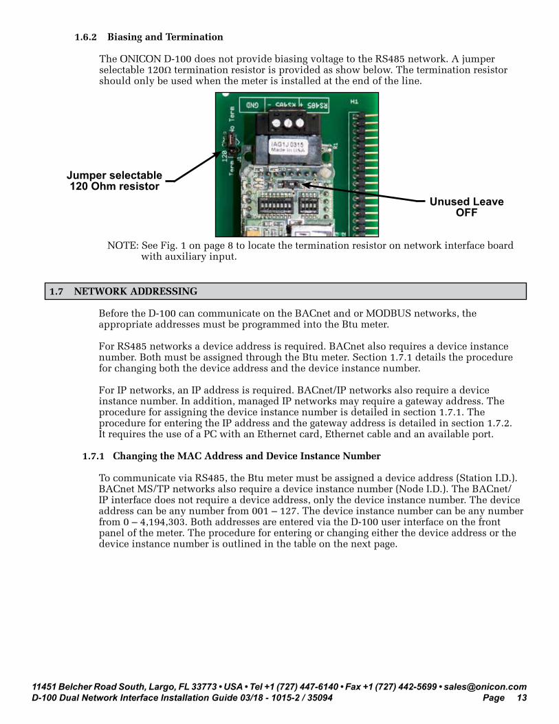
1.6.2 Biasing and Termination
The ONICON D-100 does not provide biasing voltage to the RS485 network. A jumper selectable 120Ω termination resistor is provided as show below. The termination resistor should only be used when the meter is installed at the end of the line.
NOTE: See Fig. 1 on page 8 to locate the termination resistor on network interface board with auxiliary input.
Jumper selectable120 Ohm resistor
1.7 NETWORK ADDRESSING
Before the D-100 can communicate on the BACnet and or MODBUS networks, the appropriate addresses must be programmed into the Btu meter.
For RS485 networks a device address is required. BACnet also requires a device instance number. Both must be assigned through the Btu meter. Section 1.7.1 details the procedure for changing both the device address and the device instance number.
For IP networks, an IP address is required. BACnet/IP networks also require a device instance number. In addition, managed IP networks may require a gateway address. The procedure for assigning the device instance number is detailed in section 1.7.1. The procedure for entering the IP address and the gateway address is detailed in section 1.7.2. It requires the use of a PC with an Ethernet card, Ethernet cable and an available port.
1.7.1 Changing the MAC Address and Device Instance Number
To communicate via RS485, the Btu meter must be assigned a device address (Station I.D.). BACnet MS/TP networks also require a device instance number (Node I.D.). The BACnet/IP interface does not require a device address, only the device instance number. The device address can be any number from 001 – 127. The device instance number can be any number from 0 – 4,194,303. Both addresses are entered via the D-100 user interface on the front panel of the meter. The procedure for entering or changing either the device address or the device instance number is outlined in the table on the next page.
Unused LeaveOFF

11451 Belcher Road South, Largo, FL 33773 • USA • Tel +1 (727) 447-6140 • Fax +1 (727) 442-5699 • [email protected] Dual Network Interface Installation Guide 03/18 - 1015-2 / 35094 Page 14
STEP ACTION REACTION COMMENT0 Obtain device address &
device instance number from the network administrator.
None. The device address is a three digit number from 001 – 127. The device instance number can be anything from 0 – 4,194,303.
1 With the display running, open the front panel, locate and momentarily press thepushbutton switch DEV ADD / PROG ENAB.
None. DEV ADD / PROG ENAB is located in the lower left corner of the D-100 processor board next to the DB9 connector (See appendix page A-1).
2 Momentarily press the PROGRAM pushbutton on the front panel of the display. If this is not done, the display will revert to the RUN mode after 5 minutes.
The D-100 will change to the PROGRAM mode. The top line of the LCD will indicate PPPPPPPP. The second line will read DEVICE ID and the first digit of the 3 digit MAC address will be blinking.
The PROGRAM pushbutton is on the front panel.
3 Successively press the SCROLL pushbutton to increment the number to the desired value from 0 – 9.
The blinking number increments by one each time you press the SCROLL pushbutton.
The SCROLL pushbutton is on the front panel.
4 Momentarily press the RESET pushbutton once.
The second digit will now be blinking.
The RESET pushbutton is on the front panel.
5 Successively press the SCROLL pushbutton to increment the number to the desired value from 0 – 9.
The blinking number increments by one each time you press the SCROLL pushbutton.
The SCROLL pushbutton is on the front panel.
6 Momentarily press the RESET pushbutton once.
The third digit will now be blinking.
The RESET pushbutton is on the front panel.
7 Successively press the SCROLL pushbutton to increment the number to the desired value from 0 – 9.
The blinking number increments by one each time you press the SCROLL pushbutton.
The SCROLL pushbutton is on the front panel.
8 Once the correct address is displayed, momentarily press the PROGRAM pushbutton.
The INSTNCE page is now displayed with the first digit of the device instance number blinking.
The PROGRAM pushbutton is on the front panel.
9 Use the SCROLL pushbutton and RESET pushbutton as described above to enter the new device instance number.
Each digit will increment and the RESET pushbutton will advance the blinking cursor to the next digit.
The SCROLL pushbutton and the RESET pushbutton are on the front panel.
10 Press the PROGRAM button. The FRONT PANEL RESET page appears.
It is not necessary to change anything on this page.
11 Momentarily press the PROGRAM pushbutton.
The SAVE CHANGES page appears. The new addresses must be saved to take effect.
12 Momentarily press the SCROLL pushbutton.
The “N” changes to “Y” on the SAVE CHANGES page.
The “Y” must be selected in order for the new addresses to take effect.
13 Momentarily press the PROGRAM pushbutton.
The new addresses are saved and the display will revert to the RUN mode.

11451 Belcher Road South, Largo, FL 33773 • USA • Tel +1 (727) 447-6140 • Fax +1 (727) 442-5699 • [email protected] Dual Network Interface Installation Guide 03/18 - 1015-2 / 35094 Page 15
1.7.2 Changing the IP Address, Subnet mask and Gateway Address
Changing the IP address requires a PC with an Ethernet card and an available port. The network interface is accessed using a web browser such as Internet Explorer. Both the PC and the D-100 must be configured to operate on the same IP network. Assuming the Btu meter is programmed with the default address of 192.168.1.24, configure the PC to operate with an IP address of 192.168.1.1 and a subnet mask of 255.255.255.0. Follow the procedure outlined below to edit the IP address, subnet mask and gateway address.
1. Connect an RJ45 Ethernet cable between the PC and the D-100 and power the display. Allow 60 seconds for the display firmware to cycle through start-up diagnostic routines.
2. Open Internet Explorer and enter an address of http://192.168.1.24.3. From navigation tree on the right in the image below, select setup and then network
settings.
4. Enter the new IP address, subnet mask and gateway address as needed. Click on Update IP Settings to update the settings and then click on System Restart to complete the update.
Navigation Tree
System restart required to complete the update.
Click here to upload the new settings.
11451 Belcher Road South, Largo, FL 33773 • USA • Tel +1 (727) 447-6140 • Fax +1 (727) 442-5699 • [email protected] Dual Network Interface Installation Guide 03/18 - 1015-2 / 35094 Page 16
SECTION 2.0: BACnet PICS AND OBJECTS
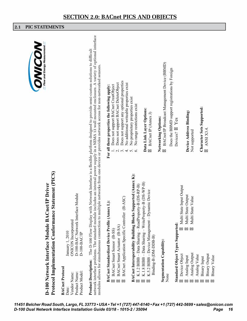
2.1 PIC STATEMENTS
•06
36
D-1
00 N
etw
ork
Inte
rfac
e M
odul
e B
AC
net/I
P D
rive
rPr
otoc
ol Im
plem
enta
tion
Con
form
ance
Sta
tem
ent (
PIC
S)
BA
Cne
t Pro
toco
l D
ate:
Ja
nuar
y 1,
201
0 V
endo
r Nam
e:
ON
ICO
N In
corp
orat
ed
Prod
uct N
ame:
D
-100
-BA
C N
etw
ork
Inte
rfac
e M
odul
e Pr
oduc
t Mod
el:
D-1
00-B
AC
/IP
Prod
uct D
escr
iptio
n:T
he
D-1
00 F
low
Dis
pla
y w
ith
Net
wor
k In
terf
ace
is a
�ex
ible
pla
tfor
m d
esig
ned
to
pro
vid
e se
mi-
cust
om s
olu
tion
s to
dif
�cu
lt
net
wor
k in
terf
ace
pro
blem
s. T
he
stan
dar
d m
odu
le i
ncl
ud
es a
n i
nte
rnal
pow
er s
up
ply
in
a N
EM
A 1
3 w
all
mou
nte
d e
ncl
osu
re. A
var
iety
of
opti
onal
in
terf
ace
mod
ule
s al
low
s fo
r si
mu
ltan
eou
s co
nn
ecti
on t
o m
ult
iple
net
wor
ks f
rom
on
e d
evic
e or
pro
vid
es n
etw
ork
acce
ss f
or n
on-n
etw
orke
d s
enso
rs.
BA
Cne
t Sta
ndar
dize
d D
evic
e Pr
ofile
(Ann
ex L
):
� B
AC
net S
mar
t Sen
sor
(B-S
S)
� B
AC
net S
mar
t Act
uato
r (B
-SA
) �
BA
Cne
t App
licat
ion
Spec
ific
Con
trolle
r (B
-ASC
)
BA
Cne
t Int
erop
erab
ility
Bui
ldin
g B
lock
s Sup
port
ed (A
nnex
K):
�
K.1
.2 B
IBB
– D
ata
Shar
ing
– R
eadP
rope
rty-B
(DS-
RP-
B)
� K
.1.8
BIB
B –
Dat
a Sh
arin
g –
Writ
ePro
perty
-B (D
S-W
P-B
) �
K.5
.2 B
IBB
– D
evic
e M
anag
emen
t – D
ynam
ic D
evic
e
Bin
ding
-B (D
M-D
DB
-B)
Segm
enta
tion
Cap
abili
ty:
Non
e
Stan
dard
Obj
ect T
ypes
Sup
port
ed:
� D
evic
e O
bjec
t
� M
ulti
Stat
e In
put O
utpu
t �
Ana
log
Inpu
t
� M
ulti
Stat
e O
utpu
t �
Ana
log
Out
put
�
Mul
ti St
ate
Val
ue
� A
nalo
g V
alue
�
Bin
ary
Inpu
t �
Bin
ary
Out
put
� B
inar
y V
alue
For
all t
hese
pro
pert
ies t
he fo
llow
ing
appl
y:
1.D
oes n
ot su
ppor
t BA
Cne
t Cre
atO
bjec
t 2.
Doe
s not
supp
ort B
AC
net D
elet
eObj
ect
3.D
oes n
ot su
ppor
t any
opt
iona
l pro
perti
es
4.N
o ad
ditio
nal w
ritea
ble
prop
ertie
s exi
st
5.N
o pr
oprie
tary
pro
perti
es e
xist
6.
No
rang
e re
stric
tions
exi
st
Dat
a L
ink
Lay
er O
ptio
ns:
� B
AC
net I
P (A
nnex
J)
Net
wor
king
Opt
ions
: �
BA
Cne
t/IP
Bro
adca
st M
anag
emen
t Dev
ice
(BB
MD
)
D
oes t
he B
BM
D su
ppor
t reg
istra
tions
by
Fore
ign
D
evic
es?
�Y
es
Dev
ice
Add
ress
Bin
ding
: N
ot su
ppor
ted
Cha
ract
er S
ets S
uppo
rted
: �
AN
SI X
3.4.

11451 Belcher Road South, Largo, FL 33773 • USA • Tel +1 (727) 447-6140 • Fax +1 (727) 442-5699 • [email protected] Dual Network Interface Installation Guide 03/18 - 1015-2 / 35094 Page 17
0602
D-1
00 N
etw
ork
Inte
rfac
e M
odul
e w
ith B
AC
net M
S/T
P In
terf
ace
Prot
ocol
Impl
emen
tatio
n C
onfo
rman
ce S
tate
men
t (PI
CS)
BA
Cne
t Pro
toco
l D
ate:
Ju
ly 1
, 200
9 V
endo
r Nam
e:
ON
ICO
N In
corp
orat
ed
Prod
uct N
ame:
D
-100
-BA
C N
etw
ork
Inte
rfac
e M
odul
e Pr
oduc
t Mod
el:
D-1
00-B
AC
Prod
uct D
escr
iptio
n:T
he
D-1
00 F
low
Dis
pla
y w
ith
Net
wor
k In
terf
ace
is a
�ex
ible
pla
tfor
m d
esig
ned
to
pro
vid
e se
mi-
cust
om s
olu
tion
s to
dif
�cu
lt
net
wor
k in
terf
ace
pro
blem
s. T
he
stan
dar
d m
odu
le i
ncl
ud
es a
n i
nte
rnal
pow
er s
up
ply
in
a N
EM
A 1
3 w
all
mou
nte
d e
ncl
osu
re. A
var
iety
of
opti
onal
in
terf
ace
mod
ule
s al
low
s fo
r si
mu
ltan
eou
s co
nn
ecti
on t
o m
ult
iple
net
wor
ks f
rom
on
e d
evic
e or
pro
vid
es n
etw
ork
acce
ss f
or n
on-n
etw
orke
d s
enso
rs.
BA
Cne
t Sta
ndar
dize
d D
evic
e Pr
ofile
(Ann
ex L
):
� B
AC
net S
mar
t Sen
sor
(B-S
S)
� B
AC
net S
mar
t Act
uato
r (B
-SA
) �
BA
Cne
t App
licat
ion
Spec
ific
Con
trolle
r (B
-ASC
)
BA
Cne
t Int
erop
erab
ility
Bui
ldin
g B
lock
s Sup
port
ed (A
nnex
K):
�
K.1
.2 B
IBB
– D
ata
Shar
ing
– R
eadP
rope
rty-B
(DS-
RP-
B)
� K
.1.8
BIB
B –
Dat
a Sh
arin
g –
Writ
ePro
perty
-B (D
S-W
P-B
) �
K.5
.2 B
IBB
– D
evic
e M
anag
emen
t – D
ynam
ic D
evic
e
Bin
ding
-B (D
M-D
DB
-B)
Segm
enta
tion
Cap
abili
ty:
Non
e
Stan
dard
Obj
ect T
ypes
Sup
port
ed:
� D
evic
e O
bjec
t
� M
ulti
Stat
e In
put O
utpu
t �
Ana
log
Inpu
t
� M
ulti
Stat
e O
utpu
t �
Ana
log
Out
put
�
Mul
ti St
ate
Val
ue
�
Ana
log
Val
ue
� B
inar
y In
put
� B
inar
y O
utpu
t
�
Bin
ary
Val
ue
For
all t
hese
pro
pert
ies t
he fo
llow
ing
appl
y:
1.D
oes n
ot su
ppor
t BA
Cne
t Cre
atO
bjec
t 2.
Doe
s not
supp
ort B
AC
net D
elet
eObj
ect
3.D
oes n
ot su
ppor
t any
opt
iona
l pro
perti
es
4.N
o ad
ditio
nal w
ritea
ble
prop
ertie
s exi
st
5.N
o pr
oprie
tary
pro
perti
es e
xist
6.
No
rang
e re
stric
tions
exi
st
Dat
a L
ink
Lay
er O
ptio
ns:
� M
S/TP
mas
ter (
Cla
use
9), b
aud
rate
up
to 7
6800
bps
�
MS/
TP sl
ave
(Cla
use
9), b
aud
rate
up
to 7
6800
bps
Dev
ice
Add
ress
Bin
ding
: N
ot su
ppor
ted
Cha
ract
er S
ets S
uppo
rted
: �
AN
SI X
3.4.

11451 Belcher Road South, Largo, FL 33773 • USA • Tel +1 (727) 447-6140 • Fax +1 (727) 442-5699 • [email protected] Dual Network Interface Installation Guide 03/18 - 1015-2 / 35094 Page 18
2.2 BAC OBJECTS
The table below contains information for each BACnet object. The D-100 operates in one of two operating modes, unidirectional or bidirectional flow. Please note that for unidirectional flow applications, Mode 2 objects are not used.
BACNET OBJECT OBJECT DESCRIPTION UNITS NOTESAnalog Input 1 Not UsedAnalog Input 2 Volume or Mass Rate GPM, GPH, MGD, L/S,
L/M, L/Hr, M³/Hr, Lb/Hr, Kg/Hr, CFS, CFM, No Units
Analog Input 3 Generic Analog Input PSI, BAR, KPA, GPM, L/S, M³/Hr, CFS, CFM, KBtu/Hr, KW, TONS, %RH, Deg F, Deg C, No Units
Analog Input 4 Generic Analog Input PSI, BAR, KPA, GPM, L/S, M³/Hr, CFS, CFM, KBtu/Hr, KW, TONS, %RH, Deg F, Deg C, No Units
Analog Value 1 Not UsedAnalog Value 2 Mode 1 Volume or Mass
TotalGallons, Liters, M³, Lbs Mass, Kg Mass, Ft³, No Units
Analog Value 3 Not UsedAnalog Value 4 Mode 2 Volume or Mass
TotalGallons, Liters, M³, Lbs Mass, Kg Mass, Ft³, No Units
Analog Value 5 Auxiliary Input Total None BACnet will not report engineering units for this object
Analog Value 6 Operating Mode (Unidirectional or Bidirectional)
Not Applicable 1 = Unidirectional3 = Bidirectional
Analog Value 12 Bidirectional Flow Indication
Not Applicable 1 = Mode 1 (forward direction)2 = Mode 2 (reverse direction)
Binary Value 11 Not Used Changing this property from the (0) inactive state to the (1) active state will reset the total to zero. (Must be priority 8 manual operator).
Binary Value 12 Zero Mode 1 Volume or Mass Total
Not Applicable
Binary Value 13 Not UsedBinary Value 14 Zero Mode 2 Volume or
Mass TotalNot Applicable
Binary Value 15 Zero Auxiliary Input Total
Not Applicable

11451 Belcher Road South, Largo, FL 33773 • USA • Tel +1 (727) 447-6140 • Fax +1 (727) 442-5699 • [email protected] Dual Network Interface Installation Guide 03/18 - 1015-2 / 35094 Page 19
2.3 ADDITIONAL BACnet® OBJECT INFORMATION
BACnet® Object Type and Number of Objects ImplementedDevice 1Analog Input 4Analog Value 7Binary Value 5
Property Default Value Read-only or Writable CommentObject Identifier Device - 57017 Writable 0-4,194,303Object Name BTU Meter - 57017 Writable 50 char. MaxObject Type Device Read-onlySystem Status Operational Read-onlyVendor Name ONICON Incorporated Read-onlyModel Name Display Module Read-onlyFirmware Rev. v2.08e Read-onlyLocation - Writable 36 char. MaxProtocol Version 1 Read-onlyProtocol Revision 1 Read-onlyServices Supported Subscribe COV, read Property, read
Property Multiple, write Property write Property Multiple, device Communication Control, reinitialize Device, time Synchronization, who-Has, who-Is
Read-only
Object Types Supported Analog input, Analog value, Binary value
Read-only
Object List (Device, 57017), (analog input, 1 – 4), (analog value, 1 – 13), (binary value, 11 – 15)
Read-only
Max ADPU Length 1458 Read-onlySegmentation Supported NO_SEGMENTATION (3) Read-onlyAPDU Timeout 10000 Read-only# of APDU Retries 3 Read-onlyMax Master 127 Read-onlyDevice Address Binding Read-only ActiveDatabase Revision 3 Read-only
11451 Belcher Road South, Largo, FL 33773 • USA • Tel +1 (727) 447-6140 • Fax +1 (727) 442-5699 • [email protected] Dual Network Interface Installation Guide 03/18 - 1015-2 / 35094 Page 20
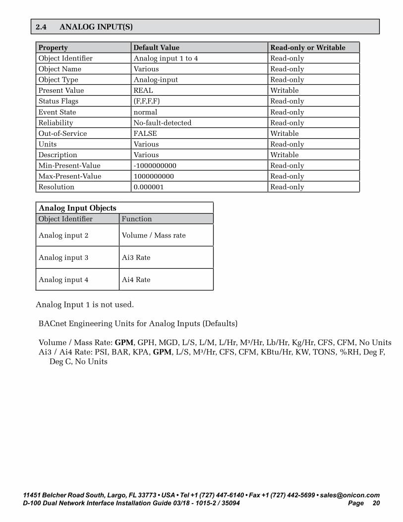
2.4 ANALOG INPUT(S)
Property Default Value Read-only or Writable Object Identifier Analog input 1 to 4 Read-onlyObject Name Various Read-onlyObject Type Analog-input Read-only
Present Value REAL WritableStatus Flags (F,F,F,F) Read-only
Event State normal Read-onlyReliability No-fault-detected Read-onlyOut-of-Service FALSE WritableUnits Various Read-onlyDescription Various WritableMin-Present-Value -1000000000 Read-onlyMax-Present-Value 1000000000 Read-onlyResolution 0.000001 Read-only
Analog Input ObjectsObject Identifier Function
Analog input 2 Volume / Mass rate
Analog input 3 Ai3 Rate
Analog input 4 Ai4 Rate
Analog Input 1 is not used.
BACnet Engineering Units for Analog Inputs (Defaults)
Volume / Mass Rate: GPM, GPH, MGD, L/S, L/M, L/Hr, M³/Hr, Lb/Hr, Kg/Hr, CFS, CFM, No UnitsAi3 / Ai4 Rate: PSI, BAR, KPA, GPM, L/S, M³/Hr, CFS, CFM, KBtu/Hr, KW, TONS, %RH, Deg F, Deg C, No Units

11451 Belcher Road South, Largo, FL 33773 • USA • Tel +1 (727) 447-6140 • Fax +1 (727) 442-5699 • [email protected] Dual Network Interface Installation Guide 03/18 - 1015-2 / 35094 Page 21
2.5 ANALOG VALUE(S)
Property Default Value Read-only or Writable Object Identifier Analog value 1 to 13 Read-onlyObject Name Various Read-onlyObject Type Analog-value Read-onlyPresent Value REAL WritableStatus Flags (F,F,F,F) Read-only
Event State normal Read-onlyReliability No-fault-detected Read-onlyOut-of-Service FALSE WritableUnits Various Read-onlyDescription Various WritablePriority Array {NULL, NULL, NULL, NULL, NULL, NULL,
NULL, NULL, NULL, NULL, NULL, NULL, NULL, NULL, NULL, NULL}
Read-only
Relinquish Default 0 Read-only
Analog Value ObjectsObject Identifier FunctionAnalog value 2 Mode 1 Volume / Mass Total Analog value 4 Mode 2 Volume / Mass TotalAnalog value 5 Aux Input TotalAnalog value 6 Operating ModeAnalog value 12 Mode 1 Mode 2 IndicationAnalog value 13 BACnet Instance
Analog value 7-11 are used internally only.
Analog value 1 & 2 are not used.
BACnet Engineering Units for Analog Values (Defaults)
Volume / Mass: Gallons, Liters, M³, Lbs Mass, Kg Mass, Ft³, No UnitsAuxiliary pulse inputs: No units (counts)
11451 Belcher Road South, Largo, FL 33773 • USA • Tel +1 (727) 447-6140 • Fax +1 (727) 442-5699 • [email protected] Dual Network Interface Installation Guide 03/18 - 1015-2 / 35094 Page 22
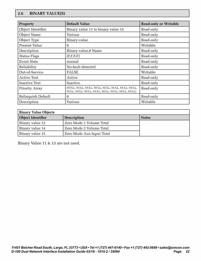
2.6 BINARY VALUE(S)
Property Default Value Read-only or Writable
Object Identifier Binary value 11 to binary value 15 Read-onlyObject Name Various Read-onlyObject Type Binary-value Read-onlyPresent Value 0 WritableDescription Binary-value,# Name Read-onlyStatus Flags (F,F,F,F) Read-only
Event State normal Read-onlyReliability No-fault-detected Read-onlyOut-of-Service FALSE WritableActive Text Active Read-onlyInactive Text Inactive Read-onlyPriority Array (NULL, NULL, NULL, NULL, NULL, NULL, NULL, NULL,
NULL, NULL, NULL, NULL, NULL, NULL, NULL, NULL)Read-only
Relinquish Default 0 Read-onlyDescription Various Writable
Binary Value ObjectsObject Identifier Description Notes Binary value 12 Zero Mode 1 Volume Total Binary value 14 Zero Mode 2 Volume Total Binary value 15 Zero Mode Aux Input Total
Binary Value 11 & 13 are not used.

11451 Belcher Road South, Largo, FL 33773 • USA • Tel +1 (727) 447-6140 • Fax +1 (727) 442-5699 • [email protected] Dual Network Interface Installation Guide 03/18 - 1015-2 / 35094 Page 23
SECTION 3.0: MODBUS MEMORY MAP
ONICON displays equipped with MODBUS serial communications provide volume rate data, and totalized volume data in a variety of engineering units. You select the engineering units you wish to use by mapping to the appropriate registers.
Also supplied with your D-100 is a document titled “Recommended MODBUS Configuration Data”. This document is different for each display. It provides a suggested list of registers to use. The recommendations are based on the calibration of the flow meter and the programming of units and multipliers displayed on the D-100.
3.1 MODBUS REGISTER FORMAT AND NETWORKING INFORMATION
1. All registers are 16 bit MODBUS Holding Registers.
2. MODBUS Holding Registers are used in 4 different ways.
A. As an Analog Value: In some cases these values are scaled by multiplying the register contents by a fixed multiplier. B. As a status indicator where the register value can only be “1” or “2”. C. As a mode indicator where the value indicates current operating mode such as “1” = single, “2” = dual, or “3” = bi-directional. D. As a control register where the host can write a value to reset total(s).
3. Registers 40001 through 40068 are unsigned integer registers (0 to 65,535) except for 40024 and 40025. These are 16 bit signed integer values (-32,768 to +32,767). Registers 41003 through 41081 are 32 bit single precision floating point values. 41001, 41002 and 41065 through 41069 are unsigned integer registers.
4. D-100 MODBUS register addresses are formatted as follows: Example: address 40001 4 = Holding register 0001 = Address that corresponds to memory location 0000
5. MODBUS function codes supported:
CODE DESCRIPTION03 Read Holding Registers06 Preset Single Registers16 Preset Multiple Registers17 Report Slave ID
i IMPORTANT NOTE
ONICON provides data in integer and floating point format. We recommend the use of floating point registers to transmit data to the network. The use of floating point data eliminates the need for scaling and additional mathematical operations to totalize energy and flow.

11451 Belcher Road South, Largo, FL 33773 • USA • Tel +1 (727) 447-6140 • Fax +1 (727) 442-5699 • [email protected] Dual Network Interface Installation Guide 03/18 - 1015-2 / 35094 Page 24
Networking Information MODBUS RTU MODBUS TCPConnection Information RS485, 2-wire half-duplex Base 10T, 10Mbps, RJ 45 ConnectionData format / Parity 8 bits, 1 stop bit / None 8 bits, 1 stop bit / NoneFlow Control (handshaking) None NoneDevice Address Range 1 - 247 1 - 247IP Address Not required Default address: 192.168.1.24Termination (selectable) 120 W or none (default none) NoneBiasing None None
3.2 MODBUS MEMORY MAP TABLE
Available Engineering Units
Engineering Units AbbreviationVolume Rate (Flow)Gallons per minute GPMGallons per minute x 10 GPM x 10Gallons per hour GPHMillion gallons per day MGDLiters per second L/SLiters per minute L/MLiters per hour L/HrCubic meters per hour M³/HrCubic meters per hour x 10 M³/Hr x 10Cubic Feet per second Ft³/SCubic Feet per minute Ft³/MMass Rate (Mass Flow) – Only available with F-2000 Flow MeterPounds per hour Lb/HrPounds per hour x 10 Lb/Hr x 10Kilograms per hour kg/HrKilograms per hour x 10 kg/Hr x 10TemperatureDegrees Fahrenheit °FDegrees Celsius °CGeneric None
Engineering Units AbbreviationVolume TotalGallons x 1,000 kGalGallons x 1,000,000 MGalGallons x 1,000,000,000 GGalLiters x 1,000 kLitersLiters x 1,000,000 MLitersLiters x 1,000,000,000 GLitersCubic Meters M³Cubic Meters x 1,000 kM³Cubic Feet Ft³Mass Total - Only available with F-2000 Flow MeterPounds x 1,000 kLbsPounds x 1,000,000 MLbsKilograms x 1,000 KkgKilograms x 1,000,000 Mkg

11451 Belcher Road South, Largo, FL 33773 • USA • Tel +1 (727) 447-6140 • Fax +1 (727) 442-5699 • [email protected] Dual Network Interface Installation Guide 03/18 - 1015-2 / 35094 Page 25
Register Address
Description Register Type Read/Write Comment
41009 Volume Rate – GPM Floating point register (1 of 2) Read Only41010 Volume Rate – GPM Floating point register (2 of 2) Read Only41011 Volume Rate – GPH Floating point register (1 of 2) Read Only41012 Volume Rate – GPH Floating point register (2 of 2) Read Only41013 Volume Rate – MGD Floating point register (1 of 2) Read Only41014 Volume Rate – MGD Floating point register (2 of 2) Read Only41015 Volume Rate – L/S Floating point register (1 of 2) Read Only41016 Volume Rate – L/S Floating point register (2 of 2) Read Only41017 Volume Rate – L/M Floating point register (1 of 2) Read Only41018 Volume Rate – L/M Floating point register (2 of 2) Read Only41019 Volume Rate – L/Hr Floating point register (1 of 2) Read Only41020 Volume Rate – L/Hr Floating point register (2 of 2) Read Only41021 Volume Rate – M³/Hr Floating point register (1 of 2) Read Only41022 Volume Rate – M³/Hr Floating point register (2 of 2) Read Only
41071 Volume Rate – Ft³/S Floating point register (1 of 2) Read Only
41072 Volume Rate – Ft³/S Floating point register (2 of 2) Read Only
41073 Volume Rate – Ft³/M Floating point register (1 of 2) Read Only
41074 Volume Rate – Ft³/M Floating point register (2 of 2) Read Only
41023 Mass Rate – Lb/Hr Floating point register (1 of 2) Read OnlyMass units are only
available when using F-2000 Vortex Meter.
41024 Mass Rate – Lb/Hr Floating point register (2 of 2) Read Only41025 Mass Rate – Kg/Hr Floating point register (1 of 2) Read Only41026 Mass Rate – Kg/Hr Floating point register (2 of 2) Read Only
41027 Supply Temperature – °F Floating point register (1 of 2) Read Only
41028 Supply Temperature – °F Floating point register (2 of 2) Read Only
41029 Return Temperature – °F Floating point register (1 of 2) Read Only41030 Return Temperature – °F Floating point register (2 of 2) Read Only
41031 Supply Temperature – °C Floating point register (1 of 2) Read Only
41032 Supply Temperature – °C Floating point register (2 of 2) Read Only
41033 Return Temperature – °C Floating point register (1 of 2) Read Only
41034 Return Temperature – °C Floating point register (2 of 2) Read Only
41075 Generic Rate Ai3 Floating point register (1 of 2) Read OnlyThere are no engineering
units associated with these registers.
41076 Generic Rate Ai3 Floating point register (2 of 2) Read Only41077 Generic Rate Ai4 Floating point register (1 of 2) Read Only41078 Generic Rate Ai4 Floating point register (2 of 2) Read Only
Register Address
DescriptionRegister Range
Data Range
Over Range
Read/Write Comment
41001 Meter Operating Mode Indicator 1 – 3 Not
applicable Read Only
1 – indicates single mode2 – indicates dual mode3 – indicates bi-directional mode
41002 Mode Status Indicator 1 – 2 Notapplicable Read Only
1 - indicates heating mode or forward direction
2 - indicates cooling mode or reverse direction

11451 Belcher Road South, Largo, FL 33773 • USA • Tel +1 (727) 447-6140 • Fax +1 (727) 442-5699 • [email protected] Dual Network Interface Installation Guide 03/18 - 1015-2 / 35094 Page 26
Register Address
Description Register Type Read/Write Comment
41047 Volume Total Mode 1 –Gal Floating point register (1 of 2) Read Only41048 Volume Total Mode 1 –Gal Floating point register (2 of 2) Read Only41049 Volume Total Mode 2 –Gal Floating point register (1 of 2) Read Only41050 Volume Total Mode 2 –Gal Floating point register (2 of 2) Read Only41051 Volume Total Mode 1 – Liters Floating point register (1 of 2) Read Only41052 Volume Total Mode 1 – Liters Floating point register (2 of 2) Read Only41053 Volume Total Mode 2 – Liters Floating point register (1 of 2) Read Only41054 Volume Total Mode 2 – Liters Floating point register (2 of 2) Read Only41055 Volume Total Mode 1 – M³ Floating point register (1 of 2) Read Only41056 Volume Total Mode 1 – M³ Floating point register (2 of 2) Read Only41057 Volume Total Mode 2 – M³ Floating point register (1 of 2) Read Only41058 Volume Total Mode 2 – M³ Floating point register (2 of 2) Read Only41079 Volume Total Mode 1 – Ft³ Floating point register (1 of 2) Read Only41080 Volume Total Mode 1 – Ft³ Floating point register (2 of 2) Read Only
41081 Volume Total Mode 2 – Ft³ Floating point register (1 of 2) Read Only
41082 Volume Total Mode 2 – Ft³ Floating point register (2 of 2) Read Only
41059 Mass Total –Lbs Floating point register (1 of 2) Read OnlyMass units are only
available when using F-2000 Vortex Meter.
41060 Mass Total –Lbs Floating point register (2 of 2) Read Only41061 Mass Total –kg Floating point register (1 of 2) Read Only41062 Mass Total –kg Floating point register (2 of 2) Read Only
41063 Auxiliary Input Total (Di3) Floating point register (1 of 2) Read Only41064 Auxiliary Input Total (Di3) Floating point register (2 of 2) Read Only
41066 Zero (+) Mode 1 Volume Total 0 – 1 0 – 1 Notapplicable Read/Write Write a value of 1 to
registers to reset totals. Re-write a value of zero to the register once the
totals reset.
41068 Zero (-) Mode 2 Volume Total 0 – 1 0 – 1 Notapplicable Read/Write
41069 Zero Auxiliary Input Total (Di3) 0 – 1 0 – 1 Notapplicable Read/Write
41070 Reserved for future use

11451 Belcher Road South, Largo, FL 33773 • USA • Tel +1 (727) 447-6140 • Fax +1 (727) 442-5699 • [email protected] Dual Network Interface Installation Guide 03/18 - 1015-2 / 35094 Page 27
REGISTER ADDRESS
DESCRIPTIONREGISTER
RANGEDATA
RANGEOVER
RANGEREAD/WRITE
COMMENT
40001 Meter Operating Mode Indicator 1 – 3 Not
applicable Read Only
1 – indicates single mode2 – indicates dual mode3 – indicates bi-directional mode
40002 Mode Status Indicator 1 – 2 Not applicable Read Only
1 - indicates heating mode or forward direction2 - indicates cooling mode or reverse direction
40009 Volume Rate – GPM 0 – 65535 0 – 65534 65535 Read Only40010 Volume Rate – GPM x 10 0 – 65535 0 – 65534 65535 Read Only40011 Volume Rate – GPH 0 – 65535 0 – 65534 65535 Read Only40012 Volume Rate – MGD 0 – 65535 0 – 65534 65535 Read Only40013 Volume Rate – L/S 0 – 65535 0 – 65534 65535 Read Only40014 Volume Rate – L/M 0 – 65535 0 – 65534 65535 Read Only40015 Volume Rate – L/Hr 0 – 65535 0 – 65534 65535 Read Only40016 Volume Rate – M³/Hr 0 – 65535 0 – 65534 65535 Read Only40017 Volume Rate – M³/Hr x 10 0 – 65535 0 – 65534 65535 Read Only
40018 Mass Rate – Lb/Hr 0 – 65535 0 – 65534 65535 Read OnlyMass units are only available when using F-2200 Vortex Meter.
40019 Mass Rate – Lb/Hr x 10 0 – 65535 0 – 65534 65535 Read Only40020 Mass Rate – kg/Hr 0 – 65535 0 – 65534 65535 Read Only40021 Mass Rate – kg/Hr x 10 0 – 65535 0 – 65534 65535 Read Only
40022 Supply Temperature – °F 0 – 65535 0 - 655.35 Not applicable Read Only
Multiply by 0.01 to read temperature to 2 decimal places.
40023 Return Temperature – °F 0 – 65535 0 - 655.35 Not applicable Read Only
40024 Supply Temperature – °C-32768
to+32767
-327.68 to
+327.67
Not applicable Read Only
40025 Return Temperature – °C-32768
to+32767
-327.68 to
+327.67
Not applicable Read Only

11451 Belcher Road South, Largo, FL 33773 • USA • Tel +1 (727) 447-6140 • Fax +1 (727) 442-5699 • [email protected] Dual Network Interface Installation Guide 03/18 - 1015-2 / 35094 Page 28
Register Address
DescriptionRegister Range
Data Range
Over Range
Read/Write Comment
40042 Volume Total Mode 1 - kGal 0 – 65535 0 – 999 Read Only Low Order40043 Volume Total Mode 1 - MGal 0 – 65535 0 – 999 Read Only Middle Order40044 Volume Total Mode 1 – GGal 0 – 65535 0 – 65534 65535 Read Only High Order40045 Volume Total Mode 2 – kGal 0 – 65535 0 – 999 Read Only Low Order40046 Volume Total Mode 2 – MGal 0 – 65535 0 – 999 Read Only Middle Order40047 Volume Total Mode 2 – GGal 0 – 65535 0 – 65534 65535 Read Only High Order40048 Volume Total Mode 1 – kLiters 0 – 65535 0 – 999 Read Only Low Order40049 Volume Total Mode 1 – MLiters 0 – 65535 0 – 999 Read Only Middle Order40050 Volume Total Mode 1 – GLiters 0 – 65535 0 – 65534 65535 Read Only High Order40051 Volume Total Mode 2 – kLiters 0 – 65535 0 – 999 Read Only Low Order40052 Volume Total Mode 2 – MLiters 0 – 65535 0 – 999 Read Only Middle Order40053 Volume Total Mode 2 – GLiters 0 – 65535 0 – 65534 65535 Read Only High Order40054 Volume Total Mode 1 –M³ 0 – 65535 0 – 999 Read Only Low Order40055 Volume Total Mode 1 – kM³ 0 – 65535 0 – 65534 65535 Read Only High Order40056 Volume Total Mode 2 –M³ 0 – 65535 0 – 999 Read Only Low Order40057 Volume Total Mode 2 – kM³ 0 – 65535 0 – 65534 65535 Read Only High Order
40058 Mass Total – kLbs 0 – 65535 0 – 999 Read OnlyMass units are only available when using F-2200 Vortex Meter.
40059 Mass Total – MLbs 0 – 65535 0 – 65534 65535 Read Only40060 Mass Total – Kkgs 0 – 65535 0 – 999 Read Only40061 Mass Total – Mkgs 0 – 65535 0 – 65534 65535 Read Only
40062 Auxiliary Input Total (Di3) 0 – 65535 0 – 999 Read Only Low Order40063 Auxiliary Input Total (x1000) 0 – 65535 0 – 65534 65535 Read Only High Order
40065 Zero (+) Mode 1 Volume Total 0 – 1 0 – 1 Not applicable Read/Write Write a value of 1 to
registers to reset totals. Re-write a value of zero to registers once the totals reset.
40067 Zero (-) Mode 2 Volume Total 0 – 1 0 – 1 Not applicable Read/Write
40068 Zero Auxiliary Input Total (Di3) 0 – 1 0 – 1 Not applicable Read/Write

11451 Belcher Road South, Largo, FL 33773 • USA • Tel +1 (727) 447-6140 • Fax +1 (727) 442-5699 • [email protected] Dual Network Interface Installation Guide 03/18 - 1015-2 / 35094 Page 29
3.3 TOTALIZATION, RESETTING TOTALS, OVER-RANGE & ROLLOVER
1. Integer Register Totalization
Holding registers 40026 through 40061 are integer registers that provide totalized, volume and mass flow data in a variety of engineering units. The registers are organized into pairs or groups of 3.
The first (low order) register is limited to a range of 0 – 999. This register rolls over to zero when the total value reaches 1,000. If the registers are in a group of 3, the second register (middle order) is also limited to a range of 0 – 999. This register also rolls over when the register value reaches 1,000.
The second, or in the case of groups of 3, third, (high order) register is scaled such that the smallest incremental value indicated is 1,000 times greater than the preceding register. An example of this is shown below.
Example - A group of 3 registers
Register Engineering Units & Scaling Current Value 40042 kGal (Gallons x 1,000) 00500 40043 MGal (Gallons x 1,000,000) 00015 40044 GGal (Gallons x 1,000,000,000) 00111 Low order + middle order + high order = Gallons Total = 111,015,500,000 or kGal Total = 111,015,500
Registers 40062 and 40063 provide totalization for the optional auxiliary pulse input option of the D-100. There are no engineering units associated with these registers.

11451 Belcher Road South, Largo, FL 33773 • USA • Tel +1 (727) 447-6140 • Fax +1 (727) 442-5699 • [email protected] Dual Network Interface Installation Guide 03/18 - 1015-2 / 35094 Page 30
2. Floating Point Register Totalization
Registers 41003 through 41082 (except 41065 - 41069) provide energy, volume and mass flow data in 32 bit single precision floating point format. The registers are organized into pairs. Each pair must be concatenated according to IEEE 754. Register order: Most significant first, least significant second. Word order: Most significant value first, least significant value second. Byte order within each word: Most significant byte first. Bit order within each byte: Most significant bit first. Registers 41063 and 41064 provide totalization for the optional auxiliary pulse input option of the D-100. There are no engineering units associated with these registers. 3. Resetting Totals
Registers 40064 through 40068 or 41065 through 41069 are integer registers that provide a mechanism to reset totals. Each reset register is associated with a group of totalizing registers and will reset all of the engineering units at the same time. Both integer and floating point registers will be reset at the same time regardless of which set of reset registers are used. To reset the totals associated with the register write a value of 1 to the register. Once the totals are reset, re-write a value of 0 to the register.
IMPORTANT NOTE
The D-100 contains internal registers for totalization. These registers will also be reset by this action.
!
i
!
!
CAUTION
The D-100 contains internal registers for totalization. These registers will eventually roll over to zero if the totals are not reset on a periodic basis. The associated MODBUS registers will also roll over to zero when this occurs. The engineering units and multipliers programmed in to the D-100 affect the point at which the totals roll over. The factory assigned engineering units and multipli-ers applied to the D-100 were chosen to eliminate the possibility of an over-range condition in the MODBUS integer registers before the display registers roll over. Changing the engineering units or multipliers at the display will affect the rollover point. Contact ONICON for technical service prior to making any changes.
4. Over-range & Rollover Conditions for Totals
All low order and middle order integer registers are designed to rollover to 0 when their totals exceed 999. The maximum value that can be totalized in high order integer registers is 65,534. A value of 65,535 is considered an over-range condition.
11451 Belcher Road South, Largo, FL 33773 • USA • Tel +1 (727) 447-6140 • Fax +1 (727) 442-5699 • [email protected] Dual Network Interface Installation Guide 03/18 - 1015-2 / 35094 Page 31
SECTION 4.0: NETWORK TROUBLESHOOTING TIPS
4.1 TROUBLESHOOTING
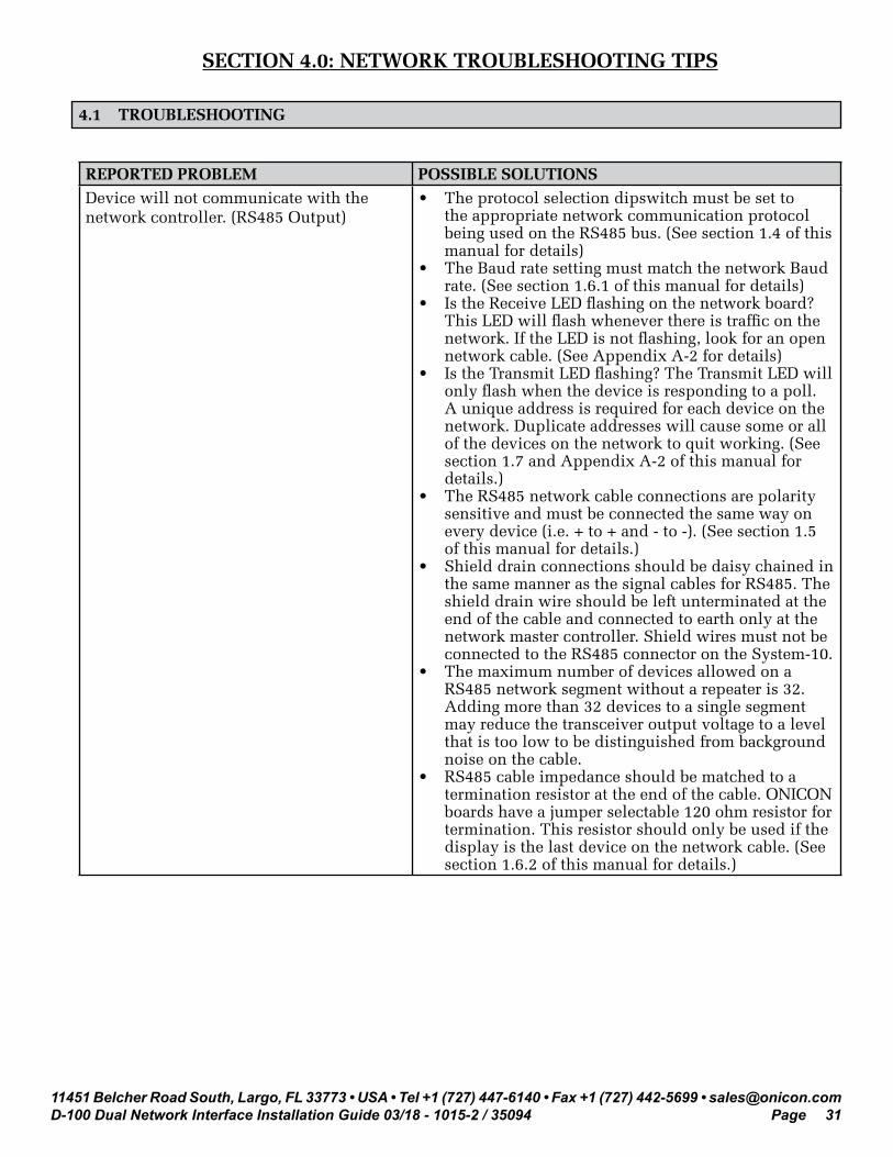
REPORTED PROBLEM POSSIBLE SOLUTIONSDevice will not communicate with the network controller. (RS485 Output)
• The protocol selection dipswitch must be set to the appropriate network communication protocol being used on the RS485 bus. (See section 1.4 of this manual for details)
• The Baud rate setting must match the network Baud rate. (See section 1.6.1 of this manual for details)
• Is the Receive LED flashing on the network board? This LED will flash whenever there is traffic on the network. If the LED is not flashing, look for an open network cable. (See Appendix A-2 for details)
• Is the Transmit LED flashing? The Transmit LED will only flash when the device is responding to a poll. A unique address is required for each device on the network. Duplicate addresses will cause some or all of the devices on the network to quit working. (See section 1.7 and Appendix A-2 of this manual for details.)
• The RS485 network cable connections are polarity sensitive and must be connected the same way on every device (i.e. + to + and - to -). (See section 1.5 of this manual for details.)
• Shield drain connections should be daisy chained in the same manner as the signal cables for RS485. The shield drain wire should be left unterminated at the end of the cable and connected to earth only at the network master controller. Shield wires must not be connected to the RS485 connector on the System-10.
• The maximum number of devices allowed on a RS485 network segment without a repeater is 32. Adding more than 32 devices to a single segment may reduce the transceiver output voltage to a level that is too low to be distinguished from background noise on the cable.
• RS485 cable impedance should be matched to a termination resistor at the end of the cable. ONICON boards have a jumper selectable 120 ohm resistor for termination. This resistor should only be used if the display is the last device on the network cable. (See section 1.6.2 of this manual for details.)

11451 Belcher Road South, Largo, FL 33773 • USA • Tel +1 (727) 447-6140 • Fax +1 (727) 442-5699 • [email protected] Dual Network Interface Installation Guide 03/18 - 1015-2 / 35094 Page 32
REPORTED PROBLEM POSSIBLE SOLUTIONSDevice will not communicate with the network controller. (BACnet IP or MODBUS TCP/IP output)
• A unique IP address is required for each device on IP network. Duplicate addresses will cause multiple devices to respond to the same poll. (See section 1.7.2 of this manual for details.)
• Managed IP networks may require that a gateway IP address be programmed into the ONICON IP device. (See section 1.7.2 of this manual for details.)
Network communications are disrupted when the device is connected. (RS485 Output)
• The Baud rate setting must match the network Baud rate. (See section 1.6.1 of this manual for details)
• Is the Receive LED flashing on the network board? This LED will flash whenever there is traffic on the network. If the LED is not flashing, look for an open network cable.
• Is the Transmit LED flashing? The Transmit LED will only flash when the device is responding to a poll. A unique address is required for each device on the network. Duplicate addresses will cause some or all of the devices on the network to quit working. (See section 1.7 of this manual for details.)
• The RS485 network cable connections are polarity sensitive and must be connected the same way on every device (i.e. + to + and - to -). (See section 1.5 of this manual for details.)
• Shield drain connections should be daisy chained in the same manner as the signal cables for RS485. The shield drain wire should be left unterminated at the end of the cable and connected to earth only at the network master controller. Shield wires must not be connected to the RS485 connector on the System-10.
Network communications are disrupted when the device is connected. (BACnet IP or MODBUS TCP/IP output)
• A unique IP address is required for each device on IP networks. Duplicate addresses will cause multiple devices to respond to the same poll. This may cause some of the devices on the network to quit working. (See section 1.7.2 of this manual for details.)
Time out errors occur when polling the device (MODBUS RS485 or MODBUS TCP/IP)
• What registers are being polled? Polling for invalid registers will slow the response time. The range of valid integer registers is 40001-40068. The range of valid floating point registers is 41003-41081.
• Resetting totals requires the network controller to write a 1 to a register in our device. This takes longer to accomplish than simply reading registers. This can lead to time out issues. When dealing with time out errors, temporarily extend the allowable delay to see if the problem will go away.

11451 Belcher Road South, Largo, FL 33773 • USA • Tel +1 (727) 447-6140 • Fax +1 (727) 442-5699 • [email protected] Dual Network Interface Installation Guide 03/18 - 1015-2 / 35094 Page 33
APPENDIX A-1 D-100 FLOW DISPLAY Computer Board
A-2 D-100 Dual Network Interface Board
A-3 D-100 Dual Network Interface Auxiliary Input Board

11451 Belcher Road South, Largo, FL 33773 • USA • Tel +1 (727) 447-6140 • Fax +1 (727) 442-5699 • [email protected] Dual Network Interface Installation Guide 03/18 - 1015-2 / 35094 Page A-1
D-100 FLOW DISPLAY COMPUTER BOARD
Reset
Temp Test
Prog ModeEnable
Device AddressProgram Enable
Serial Comm

11451 Belcher Road South, Largo, FL 33773 • USA • Tel +1 (727) 447-6140 • Fax +1 (727) 442-5699 • [email protected] Dual Network Interface Installation Guide 03/18 - 1015-2 / 35094 Page A-2
D-100 Dual Network Interface Board
120 ohm TerminationResistor
UnusedLeave OFF
Receive
Transmit

11451 Belcher Road South, Largo, FL 33773 • USA • Tel +1 (727) 447-6140 • Fax +1 (727) 442-5699 • [email protected] Dual Network Interface Installation Guide 03/18 - 1015-2 / 35094 Page A-3
D-100 Dual Network Interface Auxiliary Input Board
UnusedLeave OFF
Receive
Transmit
120 ohm TerminationResistor