cytec solutions · in electrowinning solutions ... new flocculants for improved processing of high...
TRANSCRIPT
Low pH Pyrite Flotation Collector Development Program 1
Cytec SolutionsFor Solvent Extraction, Mineral Processing and Alumina Processing
Volume 16 • February 2012
Low pH Pyrite Flotation Collector Development Program1
As we head into 2012, we are all facing another exciting year and it is clear that the pace of change in our world is continuing to accelerate. This requires us all to be more agile and flexible in our approach. At Cytec, we have continued on our strategic path of market needs driven technology innovation that allows us to “Deliver Technology Beyond our Customers’ Imagination”. When reviewing the feedback from our recent customer survey, I was pleased to see that we are meeting and in many cases exceeding your expectations in bringing innovative solutions. We remain convinced that the development and deployment of technology solutions to long term industry challenges is a source of value for both us and our customers.
The Flotation Matrix 100® and Minchem modeling tools are particularly relevant in the fast changing environment as they minimize the need for test work through careful experimental design and high quality data interpretation. In combination with our excellent capabilities in chemical design and optimization, it is possible for Cytec to continue to bring timely innovation to our customers even though the pace has quickened. Another key lever in cutting time to market is collaboration and as many of you know from personal experience this is remains key in our success.
Over the last 18 months we have brought to market ACORGA® NR, ACORGA® OR, ACORGA® OPT® 5540, EZ reagents for Electrostatic Separation, and the XR series of collectors as full or partial NaSH replacement and we are seeing strong interest in all of these products. We have also made significant progress on several other new product innovations that will be launched in 2012 including PHOSFLOW, a scale control product. We have also extended our geographic reach by establishing commercial presence in Peru and Serbia.
To address the growing demand for our Phosphine based chemistries including AEROPHINE® and CYANEX® technologies, we have recently announcement plans to significantly expand capacity at our manufacturing plant in Canada. This is a sign of our continued commitment to the mining industry and ensuring we meet future demands.
I trust that you will find the latest edition of Cytec Solutions interesting and a source of inspiration. Whether your interest is in Mineral Processing, Alumina Chemicals or Metal Extraction Products there is something here for you.
Thank you for your valued business,
Martin CourtVice President, In Process Separation
Letter from the Vice President

Low pH Pyrite Flotation Collector Development Program 11
Copper Solvent Extraction: Behavior of Iron and Manganese in Electrowinning Solutions . . . . . . . . . . . . . . . . . . . . . . . . . . . . . . . . . . . . . . . . . .
The Impact of PLS Viscosity on Solvent Extraction . . . . . . . . . . . . . . . . . . . . . . . .
Low pH Pyrite Flotation Collector Development Program . . . . . . . . . . . . . . . . .
Use of AEROPHINE® 3418A Promoter for Sulfide Minerals Flotation . . . . . . . . .
New Flocculants for Improved Processing of High Silica Bauxite . . . . . . . . . . . .
The Inhibition of Vishnevite Scale in Chinese Refineries Using MAX HT® 550 Scale Inhibitor . . . . . . . . . . . . . . . . . . . . . . . . . . . . . . . . . . . .
3
8
12
16
24
28
Table of Contents
Solvent Extractions
Mineral Processing
Alumina Processing

Cytec Mining Chemicals Business Segments2
Solvent Extraction
Almost 40 years in the solvent extraction (SX) business has translated into extensive experience and successes in solving difficult problems and in introducing many patented formulations.
Cytec offers two extraction product families: hydroxyoxime extractants under the trademark ACORGA® extraction reagents and organophosphorus derivatives under the trademark CYANEX® solvent extraction reagents.
Mineral Processing
Cytec's new reagent technologies are changing the face of the mineral processing industry. Precision targeting of chemistries yields increased recoveries, productivity and safety. Using Cytec products, customers have been able to attain an entirely new level of profitability.
Recovering maximum value from mineral ore is our primary goal. To that end, Cytec has brought advanced tools to precious and base metals operations for solving increasingly difficult problems. Cytec employs specialty collectors and reagents, dewatering aids and antiscalants. These include highly selective reagents and modifiers to provide plants with enhanced kinetics, productivity and throughput. Other advanced tools include modeling software and statistical process analysis and design tools, as well as proprietary laboratory and field tests - many of which have become industry standards.
Alumina Processing
Cytec continues to provide the alumina industry with value-adding, efficiency-enhancing technology for all stages in Bayer Process alumina production. Cytec's technological innovations for alumina processing began with programs for the solid-liquid separation processes and the introduction of synthetic polyacrylate flocculants to replace starch and have continued with a constant stream of new products.
Subsequent development of copolymers for the CCD circuit provided significant improvements in refinery economics and red mud disposal. Cytec pioneered the release of hydroxamic acid flocculants, a quantum leap in flocculant technology for the clarification circuit, providing improved economics, liquor filtration rates and reduced settler scaling.
The development of MAX HT® socialite scale inhibitor, a revolutionary product that eliminates sodalite scale from heat exchangers throughout the Bayer Process, is another testament to Cytec’s commitment to provide technologically advanced chemistry that brings real value and contributes to the sustainability of the alumina industry.
All of Cytec's initiatives in alumina are supported by a global team of field engineers - and a vertically integrated supply chain - to support today's programs and technologies with an eye to future industry needs.
www.cytec.com
3Copper Solvent Extraction: Behavior of Iron and Manganese in Electrowinning Solutions
Troy Bednarski, Matthew Soderstrom - Tempe, AZ
Introduction
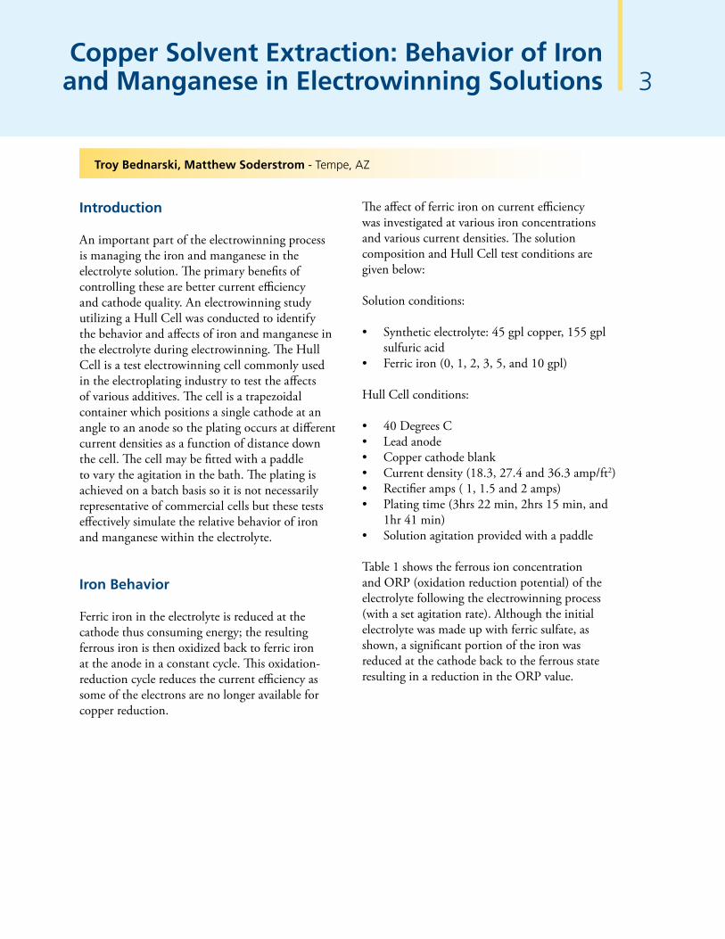
An important part of the electrowinning process is managing the iron and manganese in the electrolyte solution. The primary benefits of controlling these are better current efficiency and cathode quality. An electrowinning study utilizing a Hull Cell was conducted to identify the behavior and affects of iron and manganese in the electrolyte during electrowinning. The Hull Cell is a test electrowinning cell commonly used in the electroplating industry to test the affects of various additives. The cell is a trapezoidal container which positions a single cathode at an angle to an anode so the plating occurs at different current densities as a function of distance down the cell. The cell may be fitted with a paddle to vary the agitation in the bath. The plating is achieved on a batch basis so it is not necessarily representative of commercial cells but these tests effectively simulate the relative behavior of iron and manganese within the electrolyte.
Iron Behavior
Ferric iron in the electrolyte is reduced at the cathode thus consuming energy; the resulting ferrous iron is then oxidized back to ferric iron at the anode in a constant cycle. This oxidation-reduction cycle reduces the current efficiency as some of the electrons are no longer available for copper reduction.
The affect of ferric iron on current efficiency was investigated at various iron concentrations and various current densities. The solution composition and Hull Cell test conditions are given below:
Solution conditions:
• Synthetic electrolyte: 45 gpl copper, 155 gpl sulfuric acid
• Ferric iron (0, 1, 2, 3, 5, and 10 gpl) Hull Cell conditions:
• 40 Degrees C• Lead anode• Copper cathode blank• Current density (18.3, 27.4 and 36.3 amp/ft2)• Rectifier amps ( 1, 1.5 and 2 amps)• Plating time (3hrs 22 min, 2hrs 15 min, and
1hr 41 min)• Solution agitation provided with a paddle
Table 1 shows the ferrous ion concentration and ORP (oxidation reduction potential) of the electrolyte following the electrowinning process (with a set agitation rate). Although the initial electrolyte was made up with ferric sulfate, as shown, a significant portion of the iron was reduced at the cathode back to the ferrous state resulting in a reduction in the ORP value.
4Copper Solvent Extraction: Behavior of Iron and Manganese in Electrowinning Solutionscontinued
Table 1Percent Ferrous Iron and Oxidation-Reduction Potential
Fe+3
01235
9.5
% Fe+2
04138413938
ORP (mV)
605506502502500498
ORP (mV)
560483489489488495
ORP (mV)
615506504500498501
% Fe+2
02933313438
% Fe+2
04243383940
ORP (mV)
570625645660675690
36.6 amp/ft227.4 amp/ft218.3 amp/ft2Initial solution
ORP measured using a Ag/AgCl reference electrode with 4 M KCl filling solution
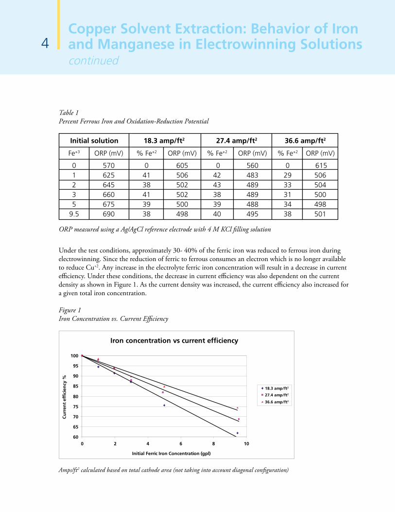
Under the test conditions, approximately 30- 40% of the ferric iron was reduced to ferrous iron during electrowinning. Since the reduction of ferric to ferrous consumes an electron which is no longer available to reduce Cu+2. Any increase in the electrolyte ferric iron concentration will result in a decrease in current efficiency. Under these conditions, the decrease in current efficiency was also dependent on the current density as shown in Figure 1. As the current density was increased, the current efficiency also increased for a given total iron concentration.
Figure 1Iron Concentration vs. Current Efficiency
Iron concentration vs current efficiency
60
65
70
75
80
85
90
95
100
0 2 4 6 8 10
Initial Ferric Iron Concentration (gpl)
Cu
rren
t ef
fici
ency
%
18.3 amp/ft2
27.4 amp/ft2
36.6 amp/ft2
Amps/ft2 calculated based on total cathode area (not taking into account diagonal configuration)
5Copper Solvent Extraction: Behavior of Iron and Manganese in Electrowinning Solutions
continued
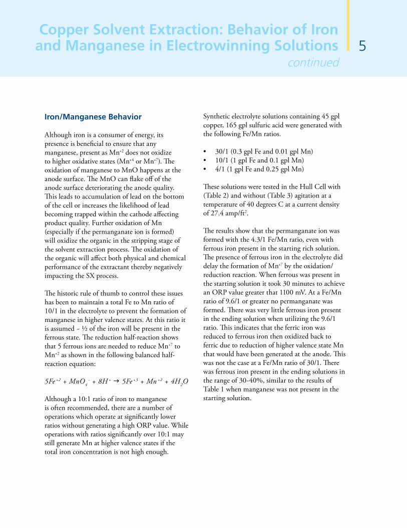
Iron/Manganese Behavior
Although iron is a consumer of energy, its presence is beneficial to ensure that any manganese, present as Mn+2 does not oxidize to higher oxidative states (Mn+4 or Mn+7). The oxidation of manganese to MnO happens at the anode surface. The MnO can flake off of the anode surface deteriorating the anode quality. This leads to accumulation of lead on the bottom of the cell or increases the likelihood of lead becoming trapped within the cathode affecting product quality. Further oxidation of Mn (especially if the permanganate ion is formed) will oxidize the organic in the stripping stage of the solvent extraction process. The oxidation of the organic will affect both physical and chemical performance of the extractant thereby negatively impacting the SX process.
The historic rule of thumb to control these issues has been to maintain a total Fe to Mn ratio of 10/1 in the electrolyte to prevent the formation of manganese in higher valence states. At this ratio it is assumed ~ ½ of the iron will be present in the ferrous state. The reduction half-reaction shows that 5 ferrous ions are needed to reduce Mn+7 to Mn+2 as shown in the following balanced half-reaction equation:
5Fe +2 + MnO4- + 8H + 5Fe +3 + Mn +2 + 4H2O
Although a 10:1 ratio of iron to manganese is often recommended, there are a number of operations which operate at significantly lower ratios without generating a high ORP value. While operations with ratios significantly over 10:1 may still generate Mn at higher valence states if the total iron concentration is not high enough.
Synthetic electrolyte solutions containing 45 gpl copper, 165 gpl sulfuric acid were generated with the following Fe/Mn ratios.
• 30/1 (0.3 gpl Fe and 0.01 gpl Mn)• 10/1 (1 gpl Fe and 0.1 gpl Mn)• 4/1 (1 gpl Fe and 0.25 gpl Mn)
These solutions were tested in the Hull Cell with (Table 2) and without (Table 3) agitation at a temperature of 40 degrees C at a current density of 27.4 amp/ft2.
The results show that the permanganate ion was formed with the 4.3/1 Fe/Mn ratio, even with ferrous iron present in the starting rich solution. The presence of ferrous iron in the electrolyte did delay the formation of Mn+7 by the oxidation/reduction reaction. When ferrous was present in the starting solution it took 30 minutes to achieve an ORP value greater that 1100 mV. At a Fe/Mn ratio of 9.6/1 or greater no permanganate was formed. There was very little ferrous iron present in the ending solution when utilizing the 9.6/1 ratio. This indicates that the ferric iron was reduced to ferrous iron then oxidized back to ferric due to reduction of higher valence state Mn that would have been generated at the anode. This was not the case at a Fe/Mn ratio of 30/1. There was ferrous iron present in the ending solutions in the range of 30-40%, similar to the results of Table 1 when manganese was not present in the starting solution.

Copper Solvent Extraction: Behavior of Iron and Manganese in Electrowinning Solutionscontinued
6
Table 2Electrowinning with Cell Agitation
(1) @ 5 min, (2) @ 30 min
Rich Electrolyte Solution Lean Electrolyte Solution
Fe/Mn
Ratio
4.3
4.3
9.6
29
32
ORP
(mV)
648
458
648
615
422
Fe+3
(gpl)
0.98
0.98
0.9
0.21
0.21
Fe+2
(gpl)
–
–
0.06
0.08
0.11
Fe+2
(%)
–
–
6.3
28
34
ORP
1115(1)
1118(2)
583
503
505
Fe+2
(gpl)
0
0.53
0
0
0.32
Fe+3
(gpl)
0.98
0.45
0.96
0.29
0
Table 3Electrowinning without Cell Agitation
Fe+3
(gpl)
0.96(1)
0.29
Fe+2
(gpl)
0
0
Fe+3
(gpl)
0.93
0.2
Fe+2
(%)
3.1
31
ORP
(mV)
587
545
Fe+2
(gpl)
0.03
0.09
ORP
(mV)
642
627
Fe/Mn
Ratio
9.6
29
Rich Electrolyte Solution Lean Electrolyte Solution

7Copper Solvent Extraction: Behavior of Iron and Manganese in Electrowinning Solutions
continued
Permanganate ion was generated even at a 9.6/1 Fe/Mn ratio when the cell was operated without agitation, ORP = 1155 at 5 min. During this test the cell agitation was turned on and the permanganate slowly started to reduce, as evidenced by a reduction of the ORP value and a diminishing of the electrolyte color from purple back to the original blue. At a Fe/Mn ratio of 29/1 cell agitation did not appear to influence the formation of the permanganate ion, apparently sufficient iron was present in the ferrous state.
Conclusion
Iron and manganese are typically present in copper PLS and can be transferred to the electrolyte by physical means (entrainment) and chemical transfer (ferric iron only). The transfer of iron to the electrolyte will reduce the current efficiency. This reduction will depend on the iron concentration in the electrolyte, the cell agitation dynamics, and the current density.
When manganese is present in the electrolyte it is important to monitor the ORP and insure the electrolyte returning to SX will not cause oxidation. This is typically achieved by having ferrous iron present in the tankhouse (rule of thumb 10/1 total iron/manganese ratio) to prevent the oxidation of Mn to higher oxidation states. At high oxidation states Mn can affect organic quality, cathode quality and cause maintenance and anode stability issues. Limiting the transfer of Mn to the electrolyte by controlling physical (A in O) entrainment is the key to minimizing potential issues.

The Impact of PLS Viscosity on Solvent Extraction8
Figure 1 Impurities Balance Scheme
Heap
PLS Pond
EW
SX RaffinatePond
Copper Cathode
H2SO4 with Impurities
Raffinate withImpurities
Cu and Impurities
ImpuritiesConcentrate
Until Equilibriumis Reached
Cu
H2SO4 Addition
Figure 1 shows the impurities balance scheme. Eventually an equilibrium is reached when the dissolving of impurities in the heap is in balance with the precipitation of impurities.
Aluminum and magnesium are two of the common impurities which tend to build-up within the PLS contributing to higher viscosities.
Figure 2 shows aluminum and magnesium concentrations in the PLS from Chilean operations.
Figure 2 Al, Mg in PLS for Chilean operations
Concentration of Aluminium and Magnesium in PLSChilean Plants
0
2
4
6
8
10
12
14
16
18
1 2 3 4 5 6 7 8 9 10 11 12 13 14 15 16 17 18 19 20 21 22 23 24 25 26 27 28
SX Plants
Al y Mg, gpl
Al Mg
Con
cent
ratio
n (g
pl)
Alexis Soto - Santiago, Chile
Introduction
In commercial scale solvent extraction, the impact of impurities in a PLS (pregnant leach solution) is frequently underestimated. Additionally, when impurities are considered, the focus tends to be on iron, chloride or nitrate depending on the origin of the ore
However, the accumulation of some other impurities like aluminum and magnesium can increase the PLS viscosities. Under these conditions poor physical behaviors may occur, including increased entrainment and/or reduced stage efficiency.
The typical PLS viscosity in Chilean solvent extraction operations is between 1.0 and 3.0 cPs. However approximately 20% of operations have viscosities significantly higher than 3.0 cPs.
Studies were conducted to evaluate impact of PLS viscosity on Cu extraction stage efficiency and phase disengagement.
PLS Impurities and Viscosity Data
During the leaching process a number of elements other than copper also leach. Depending on the water balance and solubility limits, the build-up of these impurities can vary greatly.

As shown, Al and Mg have the greatest impact while iron addition had limited affect on viscosity.
Stage Efficiency
To assess the impact of PLS viscosity on mixer efficiency kinetics curves were generated for various aqueous solutions. Each aqueous solution was prepared by diluting a real leach liquor sample (one with a high content of impurities) with water and then adjusting Cu and pH to the same original values. These solutions were mixed with a 20 Vol % ACORGA® M5640 solution at a mixer speed of 600 rpm, under organic continuity at room temperature. The copper transfer rate data was used to estimate stage efficiency assuming three stage mixing, each with one minute retention time. The results of this analysis are shown in Table 1.
Table 1Aqueous Viscosity and Calculated Stage Efficiency
Water Dilution, %
0255075
Aqueous Viscosities, cP
7.84.22.81.7
Stage Efficiency, %
91.694.195.698.3
As shown, the stage efficiency would be expected to vary from 91.6% to 98.3% dependent on the aqueous viscosity.
9The Impact of PLS Viscosity
on Solvent Extractioncontinued
Figure 3 shows PLS viscosity data for a number of the operations.
Figure 3 Viscosities in PLS for Chilean Operations
Chilean Plants
0.0
1.0
2.0
3.0
4.0
5.0
6.0
7.0
8.0
9.0
10.0
1 2 3 4 5 6 7 8 9 10 11 12 13 14 15 16 17 18 19 20
SX Plants
Visc
osity
, cP
Pregnant Leach Solution Viscosity
Synthetic solutions were prepared containing Cu, Cu/Fe, Cu/Fe/Al, Cu/Fe/Mg and Cu/Fe/Al/Mg. These solutions contained Cu=6 gpl, Fe=10 gpl, Al=15 gpl and Mg=15 gpl. The pH of each solution was adjusted with sulfuric acid to 2.35 and the viscosity of each was measured and compared to the solution containing all four metals.
Figure 4 shows the percentage contribution of each element/combination to the total viscosity.
Figure 4 Impact of Cu, Fe, Al and Mg on Viscosity
0
10
20
30
40
50
60
70
80
90
100
Cu Cu/Fe Cu/Fe/Al Cu/Fe/Mg Cu/Fe/Al/Mg
Impact of Impurities on PLS ViscositySynthetic solution, Cu 6 gpl, Fe, 10 gpl, Al 15 gpl, Mg 15 gpl
Co
ntr
ibu
tio
n o
n v
isco
sity
, %
10
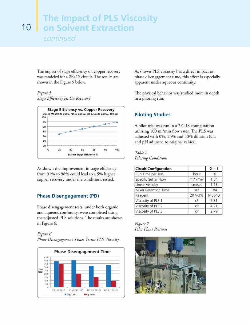
The impact of stage efficiency on copper recovery was modeled for a 2E+1S circuit. The results are shown in the Figure 5 below.
Figure 5Stage Efficiency vs. Cu Recovery
70
75
80
85
90
95
100
70 75 80 85 90 95 100
Extract Stage Efficiency %
2E+1S M5640 20 Vol%, PLS=7 gpl Cu, pH 2, LE=38 gpl Cu, 190 gpl
Stage Efficiency vs. Copper Recovery
As shown the improvement in stage efficiency from 91% to 98% could lead to a 5% higher copper recovery under the conditions tested.
Phase Disengagement (PD)
Phase disengagement tests, under both organic and aqueous continuity, were completed using the adjusted PLS solutions. The results are shown in Figure 6.
Figure 6 Phase Disengagement Times Versus PLS Viscosity
0
50
100
150
200
250
300
350
400
450
PLS 1 (7.81 cP) PLS 2 (4.21 cP) PLS 3 (2.80 cP) PLS 4 (1.69 cP)
Time (sec)
Org. Cont. Aq. Cont.
Phase Disengagement Time
The Impact of PLS Viscosity on Solvent Extraction continued
As shown PLS viscosity has a direct impact on phase disengagement time, this effect is especially apparent under aqueous continuity.
The physical behavior was studied more in depth in a piloting run.
Piloting Studies
A pilot trial was run in a 2E+1S configuration utilizing 100 ml/min flow rates. The PLS was adjusted with 0%, 25% and 50% dilution (Cu and pH adjusted to original values).
Table 2Piloting Conditions
Circuit ConfigurationRun Time per TestSpecific Setter FlowLinear VelocityMixer Retention TimeReagentViscosity of PLS 1Viscosity of PLS 2Viscosity of PLS 3
hourm3/hr*m2
cm/secsec
20 Vol%cPcPcP
2 + 116
1.541.75184
M56407.814.212.79
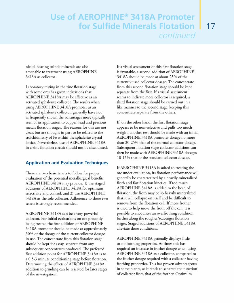
Figure 7 Pilot Plant Pictures

11The Impact of PLS Viscosity
on Solvent Extractioncontinued
Figure 8 Pilot Plant Pictures
Table 3 shows the piloting results for each aqueous solution. The high PLS viscosity resulted in significantly larger dispersion bands, and higher A in O entrainment verses the diluted PLS feeds.
Table 3Piloting Results
Test
Viscosity of PLS
Continuity E1 Stage
Extract O/A Ratio
Mixer Temperature E1 Stage
Mixer Temperature S1 Stage
Phase Disengagement E1 Stage
Dispersion Band E1 Stage
Entrainment A in O E1 Stage
Units
cP
°C
°C
sec
mm
ppm
Test 1
7.81
Organic
0.81
25.6
42.7
91
17.8
71.3
Test 2
4.21
Organic
0.86
24.9
43
84
2.8
24.2
Test 3
2.79
Organic
0.91
25.1
43
73
1
5.2
Conclusions and Recommendations
In the Latin American region, PLS viscosities under 3 cPs are common, however there are a number of operations with viscosity values significantly higher due to the build-up of impurities (primarily Al and Mg).
High aqueous solution viscosity may result in:
• Increased dispersion band depths• Increased A in O entrainment• Longer phase disengagement times,
particularly under aqueous continuity• Reduced stage efficiency• Decreased copper transfer and recovery• Increased cost to operate
The viscosity of the PLS should be monitored continuously due to potential impacts on SX performance. This is especially important for plant start-up and until a steady state is reached.

Experimental Test Procedures
Table 1 Flotation and Condition Times
Unit Operation
Conditioning 1
Concentrate 1
Conditioning 2
Concentrate 2
Time, (min)
2
6
2
6
Fresh plant pulp was taken every day from the flotation circuit feed, and diluted to 30% using plant process dilution water (pH 1-2) in a 20 liter pail. The pail was agitated using a Denver flotation machine so a 2.5 kg representative sample of pulp could be cut for flotation testing. Flotation was done using a Denver flotation machine operating at 1200 RPM's, using a 2.2 liter Denver flotation cell. Flotation times can be seen in Table 1. Collector and frother were added to the conditioning stages as required using a micro syringe (neat) or a plastic syringe as a 1% solution.
The air valve was opened full during flotation. A thirty second induction time was allotted in order to build froth. Four scrapes (once around the cell) were pulled from the flotation cell every 10 seconds. Both concentrates were collected in one pan. The concentrate and tail were filtered, dried, and assayed for copper, sulfur and iron.
Results
Test results are reported in groups by day since plant pulp was used for testing. At least one standard test using AERO 8045 promoter was run each day in order to set a benchmark for the set.
Low pH Pyrite Flotation Collector Development Program
Peter Riccio - Stamford, CT
12
Introduction
At an established Cytec customer site, low pyrite recovery has been an ongoing problem in the flotation circuit since plant commissioning in late 2004. Sulfur recovery as an indirect measure of pyrite was improved from 40% to 65% in mid-2005 when on site laboratory work confirmed that AERO® 8045 promoter was a more effective collector than AERO 407 promoter. However, sulfur recoveries above 65% could never be achieved. The customer requested the Ian Wark Research Institute[1] to complete a surface analysis study using Scanning Electron Microscopy, X-ray Photoelectron Spectroscopy, and Time-of-Flight Secondary Ion Mass Spectroscopy to determine if clay coated pyrite played a role. It was concluded that the pyrite losses to the tail are made up of a combination of coarse (+ 100um) liberated particles and finer (-200um) particles that have been coated by clay fines. The majority of the losses appear to be due to the former. A series of diagnostic tests performed in the Cytec Stamford, CT research facility using synthetic plant water showed that AERO 8045 was complexing with metal ions in solution in the harsh, slimy, low pH, environment. The complexed collector was unable to make pyrite hydrophobic, and float. The laboratory screening results showed that AERO 3302, AERO 9863, and AERO XD102 would not complex with ferric, ferrous, or copper in solution, and therefore recover more sulfur (as pyrite). Theses chemistries were then sent to the customer’s site for laboratory flotation testing.
Objective
The objective was to formulate a flotation collector in the laboratory that will recover pyrite under harsh operating conditions, and increase sulfur recovery above 75%.

13Low pH Pyrite Flotation Collector
Development Program continued
Tests CY-1 to CY-4 Alternative Collector Testing
In the first block of tests, the objective was to determine which collector chemistries could be an effective replacement for AERO 8045, and also to determine the effective dosage (see Table 2). AERO 8045 was tested at a high dose (168g/t) so as to achieve the highest sulfur recovery. A typical sulfur recovery of almost 63% was achieved using AERO 8045. AERO 3302 was tested at less than half the dosage of AERO 8045 (53g/t) and recovered 81% of the total sulfur. Almost 90% sulfur recovery was achieved when 82g/t of AERO 3302 promoter was used. Increasing the dose to 124g/t did not increase sulfur recovery. AERO 3302 was identified as a potential formulation component. A subsequent experimental design the following day was developed and completed using AERO 3302 as the formulation base.
CY-6 to CY-14 Baseline Development and Collector Blends
The objective of second experimental design was to develop a statistically significant AERO 8045 baseline recovery using replicate testing. AERO 3302 formulations were also tested for comparison.
Table 2AERO 3302 Dosage Study, Sulfur Recoveries
Test No
CY-1
CY-4
CY-2
CY-3
Collector
AERO 8045
AERO 3302
AERO 3302
AERO 3302
Collector Dose, g/t
168
53
82
124
Recovery,% S
62.61
81.39
89.97
89.08
Grade, % S
22.50
30.00
28.10
27.30
Calc Head, % S
9.92
10.87
11.24
10.45
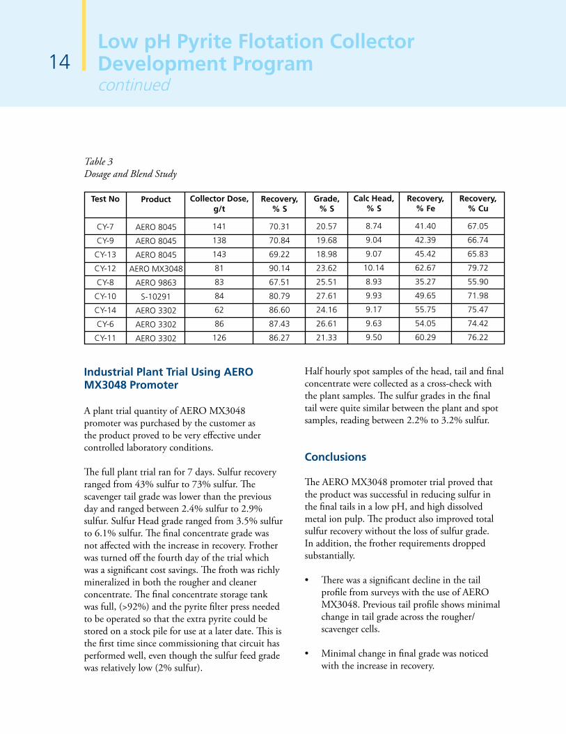
Several replicates of AERO 8045 under the same conditions were randomly completed over the course of the day to determine baseline data and test reproducibility. All gave similar results, recovering approximately 70% of the sulfur, 41% to 45% of the iron, and 65% to 67% of the copper (see Table 3).
The optimum dosage for AERO 3302 promoter is approximately 62g/t where 86% of the total sulfur was recovered. Increasing the dose to 126g/t did not significantly increase recovery. This is consistent with the previous day's work. This trend was also reflected in both iron and copper recoveries. All metal recoveries were substantially higher as compared to the AERO 8045 standard. The best metallurgy was achieved using 81g/t AERO MX3048 promoter, which is a formulated collector containing AERO 3302 and AERO XD102. AERO XD102 was identified in the screening phase, and being robust in the harsh flotation environment. AERO MX3048 recovering 90% of the total sulfur, 62.7% iron. The performance of the other formulations tested, AERO 9863 and Reagent S-10291 were inferior to AERO MX3048. AERO MX3048 was chosen for an industrial plant trial and renamed AERO MX3048 promoter.
14Low pH Pyrite Flotation Collector Development Programcontinued
Industrial Plant Trial Using AERO
MX3048 Promoter
A plant trial quantity of AERO MX3048 promoter was purchased by the customer as the product proved to be very effective under controlled laboratory conditions.
The full plant trial ran for 7 days. Sulfur recovery ranged from 43% sulfur to 73% sulfur. The scavenger tail grade was lower than the previous day and ranged between 2.4% sulfur to 2.9% sulfur. Sulfur Head grade ranged from 3.5% sulfur to 6.1% sulfur. The final concentrate grade was not affected with the increase in recovery. Frother was turned off the fourth day of the trial which was a significant cost savings. The froth was richly mineralized in both the rougher and cleaner concentrate. The final concentrate storage tank was full, (>92%) and the pyrite filter press needed to be operated so that the extra pyrite could be stored on a stock pile for use at a later date. This is the first time since commissioning that circuit has performed well, even though the sulfur feed grade was relatively low (2% sulfur).
Test No
CY-7
CY-9
CY-13
CY-12
CY-8
CY-10
CY-14
CY-6
CY-11
Product
AERO 8045
AERO 8045
AERO 8045
AERO MX3048
AERO 9863
S-10291
AERO 3302
AERO 3302
AERO 3302
Collector Dose, g/t
141
138
143
81
83
84
62
86
126
Recovery, % S
70.31
70.84
69.22
90.14
67.51
80.79
86.60
87.43
86.27
Grade, % S
20.57
19.68
18.98
23.62
25.51
27.61
24.16
26.61
21.33
Calc Head, % S
8.74
9.04
9.07
10.14
8.93
9.93
9.17
9.63
9.50
Recovery, % Fe
41.40
42.39
45.42
62.67
35.27
49.65
55.75
54.05
60.29
Recovery, % Cu
67.05
66.74
65.83
79.72
55.90
71.98
75.47
74.42
76.22
Table 3Dosage and Blend Study
Half hourly spot samples of the head, tail and final concentrate were collected as a cross-check with the plant samples. The sulfur grades in the final tail were quite similar between the plant and spot samples, reading between 2.2% to 3.2% sulfur.
Conclusions
The AERO MX3048 promoter trial proved that the product was successful in reducing sulfur in the final tails in a low pH, and high dissolved metal ion pulp. The product also improved total sulfur recovery without the loss of sulfur grade. In addition, the frother requirements dropped substantially.
• There was a significant decline in the tail profile from surveys with the use of AERO MX3048. Previous tail profile shows minimal change in tail grade across the rougher/ scavenger cells.
• Minimal change in final grade was noticed with the increase in recovery.

15
• Further reduction in tail could be achieved by operating at higher pulp levels in all the rougher and scavenger cells.
• The use of stage dosing across all rougher and scavenger cells, except for the last cell, especially with the new promoter proved to be beneficial in reducing recovery.
• There is a step change reduction in the tail grade for sulfur from the addition of the new promoter and also through operating adjustments made to the float circuit.
• The feed grade was low towards the end, hovering at 6% sulfur. However that did not affect the performance of the float plant as it normally would. Both concentrate tank level and density were high.
• The final concentrate grade remained very consistent at above 50% sulfur with various head grade and recoveries.
• AERO MX3048 promoter trial proved that the promoter was successful in reducing the tail grade step wise, thereby improving the overall sulfur recovery.
• Further trials involving stage dosing will be beneficial in reducing further the tail grade and improve sulfur recovery.
• Further adjustments and fine tuning on the operating conditions of the float circuit (i.e. froth level, pull rates and density, and possibly desliming) is likely to improve sulfur recovery.
• Addition of frother was stopped after the fourth day of the trial. AERO MX3048 appears to provide some frothing characteristics.
Low pH Pyrite Flotation Collector Development Program
continued
References
1. Bassell, Chris, Kawashima, Nobuyuki, Lewis, Andrew, Newell, Ray, Ian Wark Research Institute"Surface Analysis and pyrite flotation" Report to Lane Xang Minerals (Laos), April 2006.

16Use of AEROPHINE® 3418A Promoterfor Sulfide Minerals Flotation
Phillip Mingione - Stamford, CT
AEROPHINE® 3418A is a unique sulfide mineral promoter produced by Cytec, based on phosphine (PH3) chemistry. It has proven effective as a collector for the sulfide minerals of copper and particularly lead (galena), as well as for secondary gold and silver values. AEROPHINE 3418A has widest application as a Cu and/or Pb collector for complex ores of Cu-Zn and Pb-Zn, which frequently have significant quantities of associated precious metal values. Advantages shown in the use of AEROPHINE 3418A are improved selectivities against Zn- and Fe-sulfides, increased precious metals recoveries, reduced total collector consumptions for Cu and/or Pb flotation, and increased flotation kinetics leading to higher recoveries of these values. Operating plant, pilot plant and laboratory test data from treating different ores are presented, demonstrating the advantages in use and preferred application of AEROPHINE 3418A.
Introduction
Cytec operates the only phosphine and phosphine derivatives plant in North America, located in Niagara Falls, Ontario. Specialty chemicals manufactured at this facility are used in many diverse applications, including solvent extraction reagents. A unique phosphine-based sulfide mineral promoter, AEROPHINE 3418A, is also produced in this facility.
The origins of AEROPHINE 3418A promoter date back to the 1960's, when it was established that sulfide mineral collectors based on phosphine chemistry demonstrated efficacy. This new collector chemistry was found to provide flotation performance differing significantly from those of more traditional thiol collector chemistries such as xanthates, dithiophosphates, mercaptobenzothiazoles, thionocarbamates
and those with xanthogen groups. Some of the advantages ultimately demonstrated by AEROPHINE 3418A promoter compared to these traditional collectors include:
• Improved selectivities and recoveries in base metals flotation, particularly with complex polymetallic ores.
• Increased recoveries of precious metals associated with base metal ores.
• Greater selectivity against iron-sulfide gangue minerals.
• Rapid flotation kinetics.• Decreased collector consumption.
A further advantage observed in operating plants, but difficult to quantify, is very stable flotation circuit operation. This characteristic of AEROPHINE 3418A facilitates the optimization of circuit performance, particularly by computer control, and enables treatment of variable feeds with predictability.
Application Ore Types
AEROPHINE 3418A has found widest application in flotation of copper- and lead-sulfide minerals, particularly where these are found in complex sulfide ores containing sphalerite zinc mineralization, and ores with high levels of pyrite and/or pyrrhotite. These ore types frequently contain secondary gold and/or silver values, the recovery of which can have a significant economic impact on the profitability of an operating plant whose primary products are base metal concentrates. AEROPHINE 3418A has a particular affinity toward silver and silver-sulfides. It is also in use to treat porphyry copper ores where copper is the only base metal recovered, and has been used as collector for the recovery of Ag-jarosites. Test work has given indications that
17Use of AEROPHINE® 3418A Promoter
for Sulfide Minerals Flotationcontinued
nickel-bearing sulfide minerals are also amenable to treatment using AEROPHINE 3418A as collector.
Laboratory testing in the zinc flotation stage with some ores has given indications that AEROPHINE 3418A may be effective as an activated sphalerite collector. The results when using AEROPHINE 3418A promoter as an activated sphalerite collector, generally have not as frequently shown the advantages more typically seen of its application to copper, lead and precious metals flotation stages. The reasons for this are not clear, but are thought in part to be related to the stoichiometry of Fe within the sphalerite crystal lattice. Nevertheless, use of AEROPHINE 3418A in a zinc flotation circuit should not be discounted.
Application and Evaluation Techniques
There are two basic tenets to follow for proper evaluation of the potential metallurgical benefits AEROPHINE 3418A may provide: 1) use staged additions of AEROPHINE 3418A for optimum selectivity and control, and 2) use AEROPHINE 3418A as the sole collector. Adherence to these two tenets is strongly recommended.
AEROPHINE 3418A can be a very powerful collector. For initial evaluations on ore presently being treated,the first addition of AEROPHINE 3418A promoter should be made at approximately 50% of the dosage of the current collector dosage in use. The concentrate from this flotation stage should be kept for assay, separate from any subsequent concentrates produced. The preferred first addition point for AEROPHINE 3418A is to a 0.5-3 minute conditioning stage before flotation. Determining the effects of AEROPHINE 3418A addition to grinding can be reserved for later stages of the investigation.
If a visual assessment of this first flotation stage is favorable, a second addition of AEROPHINE 3418A should be made at about 25% of the currently used collector dosage. The concentrate from this second flotation stage should be kept separate from the first. If a visual assessment seems to indicate more collector is required, a third flotation stage should be carried out in a like manner to the second stage, keeping this concentrate separate from the others.
If, on the other hand, the first flotation stage appears to be non-selective and pulls too much weight, another test should be made with an initial AEROPHINE 3418A promoter dosage no more than 20-25% that of the normal collector dosage. Subsequent flotation stage collector additions can then be made with AEROPHINE 3418A dosages 10-15% that of the standard collector dosage.
If AEROPHINE 3418A is suited to treating the ore under evaluation, its flotation performance will generally be characterized by a heavily mineralized froth and fast flotation kinetics. If too much AEROPHINE 3418A is added to the head of flotation, the froth may be so heavily mineralized that it will collapse on itself and be difficult to remove from the flotation cell. If more frother is used to help move the froth off the cell, it is possible to encounter an overfrothing condition further along the rougher/scavenger flotation stages. Staged additions of AEROPHINE 3418A alleviate these conditions.
AEROPHINE 3418A generally displays little or no frothing properties. At times this has required an increase in frother dosage when using AEROPHINE 3418A as a collector, compared to the frother dosage required with a collector having frothing properties. This has proven advantageous in some plants, as it tends to separate the function of collector from that of the frother. Optimum

18Use of AEROPHINE® 3418A Promoterfor Sulfide Minerals Flotationcontinued
circuit frothing control can then be more readily achieved by frother dosage alone, without complications of additional frothing contributed by the collector. Alcohol frothers, such as MIBC, are generally preferred for best results, although a number of plants using AEROPHINE 3418A as a collector utilize a glycol-based frother. Staged addition of frother, with AEROPHINE 3418A as a collector, is widely practiced. This same practice generally applies to laboratory testing.
Having assay results in hand from the flotation experiments conducted, the metallurgical data will require evaluation. Particularly when dealing with Cu-Zn or Pb-Zn ores, very frequently containing Au and/or Ag values, certain evaluation techniques tend to best establish and highlight the performance characteristics of AEROPHINE 3418A.
Take as an example, a Pb-Ag-Zn ore where a majority of recoverable Ag reports to the Pb concentrate. Assume that AEROPHINE 3418A is being evaluated as the Pb circuit collector for comparison to some standard collector normally used to treat this ore. The widely used technique of graphing the cumulative concentrate grades (%Pb) vs. cumulative Pb recoveries provided by the different collector systems tested is always a good basis for initial comparisons. Very often the use of AEROPHINE 3418A will demonstrate an advantage at this level of evaluation,compared to other collectors.
Since the example ore contains three different metals of economic importance, and since the distribution of these metals within the concentrates produced has an impact on the overall economic return, evaluation of flotation test data should be carried out further.
In this instance, it would be very informative to plot Ag recovery to the Pb concentrate vs. Pb
recovery,and Zn recovery to the Pb concentrate vs. Pb recovery. This will help provide a clear picture of where Ag and Zn are reporting in relation to some comparative unit recovery of the primary metal being recovered. Under such evaluation, the use of AEROPHINE 3418A promoter frequently has demonstrated a greater recovery of Ag and/or greater rejection of Zn at some established level of Pb recovery, when compared to the same level of Pb recovery provided by a different collector system.
Of course, the mineralogical associations of the metals in question will have a large influence on the attainable metallurgical results, i.e., a selective increase in Ag recovery or decrease in Zn recovery at comparable Pb recoveries. If, for example, additional Ag recovery can only be obtained as Ag associated with sphalerite or pyrite, it will not be possible to demonstrate a selective increase in Ag recovery to the Pb concentrate through the use of different collectors. Increased selectivities against sphalerite or pyrite may actually result in a decrease in Ag recovery to Pb concentrate; this in spite of equal or improved Pb recoveries or grades when using AEROPHINE 3418A promoter as the Pb circuit collector. If this situation exists, it is suggested that Ag recoveries be compared to the sum of Pb plus Zn recoveries, plus Fe recoveries if found to be significantly influential. In this manner, a Pb collector which undesirably recovers sphalerite and pyrite, thereby seeming to produce higher Ag recoveries to Pb concentrate, may be shown as not offering any real advantage compared to the more elective collector. The plant's metallurgical objectives would define what constitutes an advantage.
Figure 1 demonstrates data evaluation from the use of AEROPHINE 3418A as the Pb collector applied to a Pb-Zn ore,compared to usage of the standard sodium isopropyl xanthate (SIPX) collector. In this example Zn recovery to the Pb

19Use of AEROPHINE® 3418A Promoter
for Sulfide Minerals Flotationcontinued
concentrate is compared to the Pb recovery. It can be seen that the use of 35 g/t AEROPHINE 3418A could reject an additional 2% of the Zn, compared to the usage of the standard 45 g/t SIPX collector, when the data are evaluated at the final Pb recovery produced by SIPX. This offers the distinct advantage of sending more Zn to the Zn circuit for recovery. At the same time, there is indication that the use of AEROPHINE 3418A can provide additional Pb recovery. When this data was originally evaluated as % Pb concentrate grade vs. Pb recovery, an advantage was noted for the use of AEROPHINE 3418A, as well. The greater metallurgical advantage of improved Zn rejection was not, however, readily apparent until the data were evaluated as described.
Figure 1Polymetallic Ore Data Evaluation
94
92
90
88
86
84
82
80
78
Pb %
Rec
ove
ry
Zn % Recovery to Pb Conc.14 16 18 20 22 24 26 28
35g/t AEROPHINE 3418A45g/t SIPX
The second tenet to follow when evaluating the performance of AEROPHINE 3418A is to test it completely on its own. This advice is based upon
applying AEROPHINE 3418A to a wide variety of ores principally for Cu and Pb flotation. If AEROPHINE 3418A is suited to treating an ore, the preponderance of data in hand indicates it will perform best generally when used as the sole collector in the circuit to which it is being applied. The conjunctive use of AEROPHINE 3418A promoter with differing collectors may have undesirable effects on the flotation performance provided by AEROPHINE 3418A.
Every "rule" has its exceptions, however, and there are a number of plants presently treating Cu-Zn ores, using AEROPHINE 3418A promoter and a dithiophosphate in the Cu flotation circuit. Generally there are significant precious metals values and secondary copper mineralization associated with chalcopyrite at these plants. The use of a dithiophosphate as a secondary collector with AEROPHINE 3418A promoter in these Cu flotation circuits has been shown to offer a metallurgical advantage. It has first been necessary to establish the flotation performance of AEROPHINE 3418A as the sole collector, so as to eliminate any undesirable effects which a secondary collector potentially may exert on the flotation system. In these circumstances the conjunctive use of AEROPHINE 3418A promoter with a dithiophosphate collector has been shown to be an acceptable collector combination, without negative impact on the resulting metallurgy. Other thiol type collectors may demonstrate suitability as secondary collectors with AEROPHINE 3418A, as well.
The conjunctive use of xanthates with AEROPHINE 3418A promoter, for Cu or Pb flotation, is very strongly discouraged. There is overwhelming data to show that such joint reagent usage diminishes the benefits provided by the AEROPHINE 3418A. The resulting metallurgy from the conjunctive use of xanthates
20Use of AEROPHINE® 3418A Promoterfor Sulfide Minerals Flotationcontinued
and AEROPHINE 3418A will trend toward that provided by xanthates used alone or, in some cases, inferior metallurgy. Particularly where xanthate is already in use for Cu or Pb flotation, the urge to initially evaluate AEROPHINE 3418A as a partial replacement for the xanthate should be resisted. In these circumstances, proper assessment of the metallurgical benefits which AEROPHINE 3418A is capable of providing can only be made when AEROPHINE 3418A is tested as the sole collector.
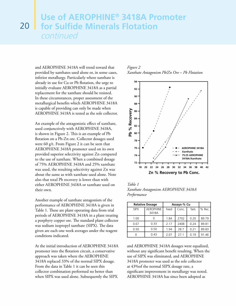
An example of the antagonistic effect of xanthate, used conjunctively with AEROPHINE 3418A, is shown in Figure 2. This is an example of Pb flotation on a Pb-Zn ore. Collector dosages used were 60 g/t. From Figure 2 it can be seen that AEROPHINE 3418A promoter used on its own provided superior selectivity against Zn compared to the use of xanthate. When a combined dosage of 75% AEROPHINE 3418A and 25% xanthate was used, the resulting selectivity against Zn was about the same as with xanthate used alone. Note also that total Pb recovery is lower than with either AEROPHINE 3418A or xanthate used on their own.
Another example of xanthate antagonism of the performance of AEROPHINE 3418A is given in Table 1. These are plant operating data from trial periods of AEROPHINE 3418A in a plant treating a porphyry copper ore. The standard plant collector was sodium isopropyl xanthate (SIPX). The data given are each one week averages under the reagent conditions indicated.
At the initial introduction of AEROPHINE 3418A promoter into the flotation circuit, a conservative approach was taken where the AEROPHINE 3418A replaced 33% of the normal SIPX dosage. From the data in Table 1 it can be seen this collector combination performed no better than when SIPX was used alone. Subsequently the SIPX
Figure 2Xanthate Antagonism Pb/Zn Ore – Pb Flotation
94
92
90
88
86
84
82
80
78
76
74
72
Pb %
Rec
ove
ry
Zn % Recovery to Pb Conc.18 20 22 24 26 28 30 32 34 36 38 40 42
Xanthate75:25 AEROPHINE 3418A/Xanthate
AEROPHINE 3418A
Table 1Xanthate Antagonism AEROPHINE 3418A Performance
Assays-% CuRelative Dosage
Feed
1.84
2.17
1.94
2.07
SIPX
1.00
0.67
0.50
0
Conc.
2702
2408
28.7
27.1
AEROPHINE3418A
0
0.33
0.50
0.43
Tails
0.20
0.24
0.21
0.19
% Rec.
89.79
89.81
89.83
91.46
and AEROPHINE 3418A dosages were equalized, without any significant benefit resulting. When the use of SIPX was eliminated, and AEROPHINE 3418A promoter was used as the sole collector at 43%of the normal SIPX dosage rate, a significant improvement in metallurgy was noted. AEROPHINE 3418A has since been adopted as

21Use of AEROPHINE® 3418A Promoter
for Sulfide Minerals Flotationcontinued
the collector at this plant, used without any other collector type. The dosage of AEROPHINE 3418A has ultimately been optimized at 10% of the former xanthate consumption.
In plant applications it may be possible to use a low xanthate dosage toward the end of Cu or Pb flotation, where little or no xanthate would be recycled to the head of rougher flotation. This possibility can exist where it is desired to recover principally iron-sulfide minerals, bearing precious metals or small amounts of the primary metal, into a low grade scavenger concentrate. The only area of application where the use of xanthate with AEROPHINE 3418A can be recommended is for activated sphalerite flotation. AEROPHINE 3418A generally has not demonstrated advantages in use as the sole collector for sphalerite as frequently as it has for the flotation of copper minerals and galena. As mentioned previously, this is thought to be due to the stoichiometry of Fe within the sphalerite crystal lattice. Use of a xanthate with AEROPHINE 3418A in Zn flotation has given promising results with some ores.
A peculiar characteristic of AEROPHINE 3418A promoter, seen only in laboratory flotation investigations, is its tendency to sometimes produce better selectivities with increasing dosages. This phenomenon has been noted with a number of ores by different investigators. The reasons for the occurrence of this phenomenon in laboratory flotation are not known, but it is noteworthy that it has not been observed in actual plant application. There has, in fact, been a general tendency for effective plant dosages of AEROPHINE 3418A promoter to be lower than what may have been indicated in laboratory investigations.
Figure 3 demonstrates increased selectivity against Zn with increased AEROPHINE 3418A dosage, when applied to laboratory Pb flotation on a Pb-Zn ore.
Figures 3, 4 & 5Laboratory Dosage Selectivity Phenomenon
Pb/Zn Ore – Pb Flotation97
96
95
94
93
92
91
90
89
88
87
Cu
% R
eco
very
18 20 22 24 26 28 30 32
Zn % Recovery to Cu Conc.
60g/t AEROPHINE 3418A
42g/t AEROPHINE 3418A
Pyrrhotitic Cu Ore
35g/t AEROPHINE 3418A40g/t AEROPHINE 3418A
30g/t AEROPHINE 3418A
Cu
% R
eco
very
90
85
80
75
70
65
60
55
50
% Cu Conc. Grade8 10 12 14 16 18 20
Cu/Zn Ore – Cu Flotation97
96
95
94
93
92
91
90
89
88
87
Cu
% R
eco
very
10 12 14 16 18 20 22 24 26 28 30 32 34
Zn % Recovery to Cu Conc.
10g/t AEROPHINE 3418A
7.5g/t AEROPHINE 3418A
22Use of AEROPHINE® 3418A Promoterfor Sulfide Minerals Flotationcontinued
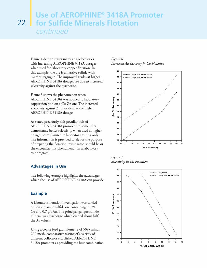
Figure 4 demonstrates increasing selectivities with increasing AEROPHINE 3418A dosages when used for laboratory copper flotation. In this example, the ore is a massive sulfide with pyrrhotitegangue. The improved grades at higher AEROPHINE 3418A dosages are due to increased selectivity against the pyrrhotite.
Figure 5 shows the phenomenon when AEROPHINE 3418A was applied to laboratory copper flotation on a Cu-Zn ore. The increased selectivity against Zn is evident at the higher AEROPHINE 3418A dosage.
As stated previously, this peculiar trait of AEROPHINE 3418A promoter to sometimes demonstrate better selectivity when used at higher dosages seems limited to laboratory testing only. The information is provided solely for the purpose of preparing the flotation investigator, should he or she encounter this phenomenon in a laboratory test program.
Advantages in Use
The following example highlights the advantages which the use of AEROPHINE 3418A can provide.
Example
A laboratory flotation investigation was carried out on a massive sulfide ore containing 0.67% Cu and 0.7 g/t Au. The principal gangue sulfide mineral was pyrrhotite which carried about half the Au values.
Using a coarse feed granulometry of 50% minus 200 mesh, comparative testing of a variety of different collectors established AEROPHINE 3418A promoter as providing the best combination
Figure 6 Increased Au Recovery in Cu Flotation
Au
% R
eco
very
40
38
36
34
32
30
28
26
24
22
20
18
16
70 72 74 76 78 80 82 84 86 88 90 92
Cu % Recovery
30g/t AEROPHINE 3418A
50g/t AEROPHINE 3418A
Figure 7 Selectivity in Cu Flotation
4 5 6 7 8 9 10 11 12 13
Cu
% R
eco
very
% Cu Conc. Grade
92
90
88
86
84
82
80
78
76
74
72
70
30g/t AEROPHINE 3418A
50g/t SIPX

23Use of AEROPHINE® 3418A Promoter
for Sulfide Minerals Flotationcontinued
of Cu and Au recoveries, and selectivity against pyrrhotite. These benefits are illustrated in Figures 6 and 7.
Figure 6 compares Cu vs. Au recoveries for a test made using 30 g/t AEROPHINE 3418A and another made using 50g/t SIPX, both with a flotation pH 10.1. Both tests produced Cu recoveries of 90-91%. The test made with AEROPHINE 3418A, however, recovered significantly more Au per unit of Cu recovery than did the test with SIPX. The use of AEROPHINE 3418A promoter also demonstrated improved concentrate grades, illustrated in Figure 7, compared to those produced by SIPX. This was principally due to better selectivity against pyrrhotite.
Since a large portion of Au contained in the ore is associated with the pyrrhotite, yet AEROPHINE 3418A promoter was shown to be more selective against pyrrhotite than SIPX, the increased Au recovery produced by AEROPHINE 3418A is attributed to improved recovery of some portion of Au existing in a liberated state.
Conclusions
AEROPHINE 3418A is a unique sulfide mineral promoter, based on phosphine chemistry. It has found widest application for flotation of copper-sulfides and galena, particularly where these are found in complex polymetallic ores containing sphalerite, and ores with high levels of pyrite and/or pyrrhotite. Use of AEROPHINE 3418A has demonstrated improved recoveries of base metals and associated precious metals, with excellent selectivity characteristics against iron-sulfide gangue minerals and depressed sphalerite. Other advantages seen in use are rapid flotation kinetics, and decreased collector consumption compared
to more traditional thiol type collectors. The unique flotation performance characteristics of AEROPHINE 3418A can best be realized when AEROPHINE 3418A is evaluated according to recommended application techniques.

24New Flocculants for Improved Processing of High Silica Bauxite
Qi Dai, Matt Davis - Stamford, CT, Ruzi Zhang - Shanghai, China
Introduction
An important element in the production of alumina from bauxite is an effective solid-liquid separation in gravity thickeners to generate sodium aluminate liquor containing low amounts of suspended solids. This process relies heavily on synthetic flocculants that are introduced to the slurry feed to enhance the aggregation of red mud particles and accelerate the settling of the red mud. Over the years, new reagents have been developed to improve this separation, which include the high molecular weight polyacrylates and hydroxamated polyacrylamides that are routinely used today[1, 2].
Despite their widespread utility, these flocculants are not always able to deal with the settling problems brought on by the decreasing quality of bauxite. One such example is with increasing reactive silica levels in the bauxite. In the Bayer process, silica and silicate minerals (mainly kaolinite) react with caustic liquor to form sodalite or DSP (desilication products) particles having the general formula 3(Na2O•Al2O3•2SiO2•0-2H2O)•2Na2X, where X is an anionic species such as OH-, Cl-, CO2
3- or SO42- [3]. The 2-step
reaction is thought to proceed according to the following chemical reactions[3, 4]:
3 Al2Si2O5(OH)4 + 18 NaOH→ 6 Na2SiO3 + 6 NaAl(OH)4 + 3 H2O (1)
6 Na2SiO3 + 6 NaAl(OH)4 + Na2X → Na6[Al6Si6O24]•Na2X + 12 NaOH + 6 H2O (2)
Additional species can accompany DSP in the mud depending upon factors such as liquor chemistry and impurity mineral phases present in the bauxite. These phases include calcium aluminosilicates, calcium silicates, titanium dioxide and calcium titanate. The presence of fine
particles of DSP and these other phases can have a negative impact on overflow clarity, overflow filtration, mud settling and compaction[5, 6] which cannot be overcome by using conventional flocculants and often result in flow cuts. Therefore Cytec Industries has responded to the need for further improvements in flocculant technology to meet the challenges put forth by the industry’s increased utilization of low quality bauxite ores.
This paper highlights a new family of polymers incorporating silane functionality that show improved flocculation of suspended silicate and titanate solids in the Bayer process[7]. The development of these reagents and the corresponding performance on slurries generated from processing high silica gibbsitic bauxite has been discussed elsewhere[8]. This publication represents an extension of this technology to settler and washer applications at plants processing high silica diasporic bauxite (with and without sweetening with gibbsitic bauxite), a subject particularly applicable to the alumina industry in China. Data from laboratory settling experiments demonstrating the performance of these polymers on slurry from representative Bayer refineries are presented.
Experimental
The performance of the new flocculant was tested on red mud slurries collected on-site at a number of alumina refineries. The data from static cylinder tests were used to compare results obtained from the use of the new silane-containing polymers to those using only a polyacrylate flocculant.
On-site evaluation of new reagents at several refineries was conducted by obtaining thickener feed and transferring to 500 ml graduated cylinders to conduct laboratory settling tests.

25New Flocculants for Improved
Processing of High Silica Bauxitecontinued
For experiments evaluating the performance in the washers, appropriate ratios of overflow and underflow were combined to yield representative slurries. To account for variation between batches, measurement of slurry solids and liquor analysis were performed on at least two cylinders per batch.
In all experiments, the polyacrylate flocculant was added to the slurry using a single addition, followed by 5 gentle mixing strokes of a perforated plunger. In experiments evaluating the developmental product CYFLOC™ SA settling aid (one of the new flocculants), the polymer was dosed prior to the standard addition of the polyacrylate as described above. A polyacrylate flocculant dose was chosen to achieve settling rates representative of the plant, which were calculated by timing the descent of the mud interface, and these experiments were treated as the control. After flocculant addition and mixing were complete, the cylinders were left in a water bath for a fixed time, after which the supernatant clarity was measured gravimetrically by filtering an aliquot of the overflow liquor. When this was not possible, overflow clarity was determined with a turbidimeter.
Results and Discussion
The dose response of CYFLOC SA was investigated on settler feed slurry at a Bayer refinery that was processing diasporic bauxite with an average reactive silica level of 13% and A/S (alumina to silica) ratio = 5. The dosage of the new polymer was varied between 0 and 408 g/T which was added in combination with a fixed dosage of polyacrylate flocculant (522 g/T). Mud solids were measured to be 98 g/L. Because it was not possible to measure supernatant solids gravimetrically, the performance of the new polymer was assessed by measuring the turbidity of the supernatant. The
settling rate results, along with the supernatant turbidity on the secondary axis, are displayed in Figure 1.
Figure 1Settling Rate (diamonds) and Supernatant Turbidity (triangles) Data As a Function of CYFLOC SA Dose When Dosed to Slurry Obtained While Processing Diasporic Bauxite. In all experiments, the polyacrylate dose was held constant at 522 g/ton.
0
50
100
150
200
250
300
350
0
2
4
6
8
10
0 75 150 225 300 375 450
Sup
ernatan
t Turb
idity (N
TU)
Sett
ling
Rat
e (m
/hr)
CYFLOC SA Dose (g/ton)
Settling RateTurbidity
As seen in Figure 1, increasing the dose of CYFLOC SA results in a doubling in settling rate. This large improvement in settling rate is not accompanied with a significant change in the supernatant turbidity.
The dose response of the same reagent, CYFLOC SA, was investigated on plant slurry collected from another Bayer refinery that was processing diasporic bauxite while sweetening with 10% gibbsitic bauxite. The dosage of the polymer was varied between 0 and 481 g/ton which was added in combination with a fixed dosage of polyacrylate (154 g/ton). The settling rate and supernatant clarity results are displayed in Figure 2.

26New Flocculants for Improved Processing of High Silica Bauxitecontinued
Figure 2Settling Rate (diamonds) and Supernatant Turbidity (triangles) Data As a Function of CYFLOC SA Dose When Dosed to Slurry Obtained While Processing Diasporic Bauxite and Sweetening with 10% Gibbsitic Bauxite. In all experiments, the polyacrylate dose was held constant at 154 g/ton.
0
1
2
3
4
5
0
4
8
12
16
0 100 200 300 400 500
O/F C
larity (g/L)
Sett
ling
Rat
e (m
/hr)
CYFLOC SA Dose (g/ton)
Settling RateClarity
From the data in Figure 2, it is clear that addition of the new polymer to red mud slurries results in improved supernatant clarity compared to the addition of conventional flocculants alone. This improvement in clarity was also accompanied by an improvement in settling rate, with observed increases up to 80%. These results illustrate the applicability of this reagent to improve the settling performance of slurry when the plant is processing high silica diasporic bauxite and practicing sweetening with gibbsitic bauxite.
During the course of our evaluations at Bayer refineries, we also observed that improved performance in the mud washing circuit could be realized by the addition of CYFLOC SA. The dose response of the new polymer was established on feed to the 2nd washer of a Bayer refinery processing high silica diasporic bauxite. The dosage of the polymer was varied between 0 and 111 g/ton which was added in combination with a fixed dosage of polyacrylate (120 g/ton). The settling rate and supernatant turbidity results are displayed in Figure 3.
Figure 3Settling Rate (diamonds) and Supernatant Turbidity (triangles) Data As a Function of CYFLOC SA Dose When Dosed to Slurry Feed from the 2nd Washer. In all experiments, the polyacrylate dose was held constant at 120 g/ton.
0
50
100
150
200
250
0
2
4
6
8
10
0 50 100 150
Sup
ernatan
t Turb
idity (N
TU)
Sett
ling
Rat
e (m
/hr)
CYFLOC SA Dose (g/ton)
Settling RateTurbidity
From the settling test data in Figure 3, it is apparent that CYFLOC SA can significantly improve flocculation performance in washers, resulting in faster settling rates and lower overflow solids. The data from these experiments show a settling rate more than double that which is obtained by the addition of polyacrylate alone. This is accompanied by a large reduction in the supernatant turbidity.
In the mining industry, the dual polymer program is widely used, in which a low molecular weight polymer is added first followed by a high molecular weight polymer. The role of the low molecular weight polymer (often referred to as coagulant) is to form small mud particle aggregates which can subsequently be flocculated by the high molecular weight flocculant more efficiently than the case of single polymer program. There is also a variety of choice of the low molecular weight polymer; cationic, anionic, inorganic and organic[9]. However, in the Bayer process, flocculation of red mud is almost solely achieved by high molecular weight polymers with occasional cases involving lime and dextran as

27New Flocculants for Improved
Processing of High Silica Bauxitecontinued
flocculation aids. Attempts have been made in the past to find or develop coagulant type of polymers to aid red mud flocculation without much success. This new polymer is the first of this kind that has shown significant improvement in this area.
Conclusions
1. Laboratory results conducted with plant slurry demonstrate the effectiveness of new silane-containing polymers for improved flocculation of muds generated from processing high silica diasporic bauxite.
2. A 2-3 time improvement in settling rate was observed on multiple substrates obtained from different plants when CYFLOC SA was added in combination with a conventional polyacrylate flocculant.
3. In most cases, this settling rate improvement was also accompanied by a significant improvement in overflow clarity by capturing particles that would normally report to the settler overflow.
4. CYFLOC SA was also shown to be effective at improving flocculation efficiency in the mud washing circuit.
References
1. Rothenberg, A.S., Spitzer, D.P., Lewellyn, M.E., and Heitner, H.I., New reagents for alumina processing, Light Metals, (1989), pp. 91-96
2. Ryles, R.G., and Avotins, P.V., "Superfloc® HX*, a new technology for the alumina industry" (4th International Alumina Quality Workshop, Darwin, Northern Territory, 1996), pp. 206-216.
3. Whittington, B.I., Fletcher, B.L., and Talbot, C., The effect of reaction conditions on the composition of desilication product (DSP) formed under simulated Bayer conditions, Hydrometallurgy, Vol. 49, (1998), pp. 1-22.
4. Smith, P., The processing of high silica bauxites -- Review of existing and potential processes, Hydrometallurgy, Vol. 98, (2009), pp. 162-176.
5. Peiwang, L., Zhijian, L., Yucai, L., Hailong, C., Fengling, W., and Hong, W., The influence of the predesilication temperature of bauxite slurry on the sedimentation of red mud and the utilization of which in alumina production, Light Metals, (1994), pp. 133-136.
6. Li, S.-M., Ge, L.-Y., and Zeng, X.-Q., The simulation experiment about silica to the settling of red mud separation process, Ziran Kexueban, Vol. 36, No. 3 (2007), pp. 18-20.
7. Dai, Q., Spitzer, D., Heitner, H.I., and Chen, H.-L.T., Use of silicon-containing polymers to improve red mud flocculation in the Bayer process, US Patent Application 2008/0257827 A1, (2008).
8. Davis, M., Dai, Q., Chen, H.-L.T., and Taylor, M., New Polymers for Improved Flocculation of High DSP-Containing Muds, Light Metals, (2010), pp. 57-61.
9. Heitner, H.I., Foster, T., and Panzer, H.P., "Mining Applications" (Encyclopedia of Polymer Science and Engineering, 2nd Ed., Vol. 9, 1987), p. 824.

M. Soderstrom, T. Bednarski, H. Yanez, A. Soto, E. Kamenetzky and V. Cocalia
The Inhibition of Vishnevite Scale in Chinese Refineries Using MAX HT® 550 Scale Inhibitor28
Qi Dai, John Carr, Frank Kula, Jerome O’Keefe - Stamford, CT
Introduction
Silica present in bauxite dissolves under Bayer alumina digestion conditions and subsequently precipitates as a sodium aluminosilicate, “desilication product” (DSP). This precipitation occurs as scaling on the inside of the heat exchange tubes and causes significant loss of heat transfer. The impact of scale and options for dealing with the scaling problem is well documented[1,2]. The current method to clean the heater tubes is a combination of acid and mechanical cleaning that is unsatisfactory from an economical, safety, and efficiency perspective[3].
In 2004, Cytec developed the MAX HT® technology to prevent the aluminosilicate scale growth in refinery evaporators and heat exchangers[4]. Since then MAX HT has successfully eliminated the formation of sodalite scale under various process conditions[2,3,5,6]. This technology was originally limited to double stream refineries, becoming ineffective at high solids (single stream) and low solids conditions. A second generation product, MAX HT® 550, was developed that was shown to work more robustly at low solid levels encountered in some double stream refineries[7, 8].
The effectiveness of MAX HT is influenced by the type of scale (mineralogy) formed at a particular refinery. Development work focused on inhibiting sodalite scale that is prevalent in many Bayer plants. When scale other than sodalite is predominant, MAX HT technology may have reduced effectiveness requiring increased dosages to inhibit scale formation. The tendency and type of aluminosilicate scale to form in a particular refinery will depend on a wide variety of factors, related primarily to the type of bauxite and process conditions. Table 1 shows some characteristics of the scales in various regions of the world. Chinese refineries have been shown to form vishnevite type
scale instead of sodalite or cancrinite commonly found in other regions. This difference originates from the type of the bauxite and impurity minerals associated with it. Most vishnevite scale is found in Chinese refineries which process domestic diasporic bauxite. Some Chinese refineries process imported gibbsitic bauxite, and evaporator scale in those refineries is exclusively sodalite (not shown in Table 1).
Performance testing of MAX HT in China began with the first generation product in diasporic and gibbsitic bauxite refineries. Standard laboratory tests showed that the product performed well in both refineries, achieving complete inhibition of sodium aluminsilicate at expected dosages (typically 15-40 ppm). The test work continued after the development of the second generation MAX HT. More recently, we discovered that the second generation product is not only more solids tolerant but also more effective in inhibiting vishnevite scale than the first generation product. This paper presents the laboratory results simulating the formation and inhibition of vishnevite scale using both first generation MAX HT and second generation (MAX HT 550) scale inhibitors.
Vishnevite Scale
Chemically, sodium aluminosilicate scale is usually either sodalite or cancrinite, with cancrinite the predominant scale in higher temperature plants. Vishnevite forms a solid solution series with cancrinite in which the main substitution is between CO3 and SO4. K
+ incorporation may also occur.

29The Inhibition of Vishnevite Scale in Chinese
Refineries Using MAX HT® 550 Scale Inhibitorcontinued
• Cancrinite (Na, Ca)7-8(Al6Si6O24) (CO3, SO4, Cl)1.2-2.0 1-5H2O
• Vishnevite (Na,Ca,K)6-7(Al6Si6O24) (SO4, CO3, Cl)1.0-1.5 1-5H2O
• Sodalite Na8(Al6Si6O24) Cl
Structurally, sodalite has a roughly spherical unit cell of ca. 9Å and is isometric (cubic). Vishnevite and cancrinite have rod like structures and unit cells of ca. 12.7 X 5.15 Å and are both hexagonal. All have very open structures and, as a result, low densities that probably contribute to their ability to lower heat exchanger efficiency.
Vishnevite scale is a unique type of aluminosilicate scale commonly found in evaporators in Chinese refineries processing domestic bauxite. While
the chemistry of all evaporator scales is sodium aluminosilicate, vishnevite scale contains markedly more SO3 and K2O than sodalite and cancrinite scales (Table 1).
Domestic Chinese bauxite is predominantly diasporic, and has high amounts of clay minerals including kaolinite, illite and pyrophyllite[9,10]. The preference of forming vishnevite scale over sodalite and cancrinite is due to the impurity minerals in Chinese bauxite, especially illite and pyrite. As described above, vishnevite forms when K substitutes some Na and SO4
- is incorporated as anions in the crystal. Illite is the source of K+, and pyrite is the source of SO4
-. The presence of SO4-
can promote the formation of vishnevite[11].
Table 1Scales from Various Bayer Refineries in Different Regions
Plant
A
B
C
D
E
F
G
H
I*
J*
K*
L*
Region/ Country
Europe
Australia
South America
North America
North America
Asia
Asia
China
China
China
China
China
Scale from
Evaporator
Digester heater
--
Digester heater
Evaporator
Evaporator 1st Eff
Evaporator 2nd Eff
Evaporator
Evaporator
Evaporator 1st Eff
Evaporator 1
Evaporator 2
Evaporator
Pregnant liquor heat exchanger
Scale
Cancrinite
Cancrinite and Vishnevite
Sodalite
Cancrinite
Sodalite
Sodalite
Cancrinite
Sodalite
Vishnevite
Vishnevite
Vishnevite
--
Vishnevite and Sodalite
SO3
3.8
1.4
1.5
11
4.4
--
1.7
--
7.8
6
4
4.56
4.06
K2O
0.5
0.4
0.7
0.2
0.7
--
0.04
--
10
16
7
3.17
2.15
CaO
0.05
0.1
0.3
0.1
0.2
--
0.04
--
0.05
3.5
1
0.26
1.14
Wt% in scale
*Chinese refineries processing diasporic bauxite

30The Inhibition of Vishnevite Scale in Chinese Refineries Using MAX HT® 550 Scale Inhibitorcontinued
Figure 1 below shows initial synthetic attempts at forming vishnevite scale in the laboratory by altering various liquor/digestion conditions.
Figure 1 XRD Spectrum of an Initial Attempt at Making Vishnevite Scale in the Laboratory
0
500
1000
1500
2000
2500
01-071-5356> Sodalite - Na8(Al6Si6O24)
01-070-8054> Quartz- α - SiO2
01-086-1155> Anatase - Ti0.784O2
10 20 30 40 50 60 70
Two-Theta (deg)
I(C
ou
nts
)
[S20085-101C.raw] carbonate scale - 1ds1ss0.3mmrs
Figures 2 and 3 show the effect of incorporating increasing amounts of potassium hydroxide in the synthetic liquor. Vishnevite scale was successfully formed followed by a phase that had higher degree of potassium cation substitution.
Figure 2 X-ray Diffraction Spectrum of a Laboratory Prepared Vishnevite Scale with 25% NaOH Replaced with KOH in the Liquor
10 20 30 40 50 60 700
500
1000
1500
2000
2500
3000
3500
Inte
nsi
ty(C
ou
nts
)
[S20146-6-14raw.raw]
00-046-1333> Vishnevite - Na8Al6Si6O24(SO4)-2H2O
Two-Theta (deg)
Methodology
Details of the laboratory scale inhibition test can be found in[1,2]. The same method is used in both the Cytec R&D laboratories and in alumina refinery laboratories. In the Cytec laboratories, tests are performed primarily in synthetic Bayer liquors containing 0.8 g/L SiO2, 45 g/L Al2O3, 160 g/L NaOH, 40 g/L Na2CO3 and 20 g/L Na2SO4. The composition was designed to promote reasonable amount of sodalite precipitation in the liquor in 16 hours. To generate vishnevite solids, the formulation was modified by substituting 50% NaOH replacement with KOH (on a molar basis). Increasing Na2SO4 above 20 g/L did not seem to promote the formation of vishnevite.
The test method allows for a large number of tests to be done rapidly with results that have proven to be predictive of performance. The amount of precipitated solids in each test is used as a measure of inhibition performance; the less the precipitation, the better the performance.
Analytical Characterization
The major mineral phases associated with synthetically prepared and Bayer plant scales were determined by x-ray diffraction (XRD) using a Rigaku Multiflex spectrometer. Elemental data were obtained via x-ray fluorescence (XRF) using a Rigaku ZSX Primus II wavelength dispersive spectrometer. Vibrational spectroscopy was conducted at an outside laboratory with a Kaiser Holoprobe dispersive Raman spectrometer using 785nm laser excitation to confirm the presence of vishnevite scale in synthetically prepared samples.
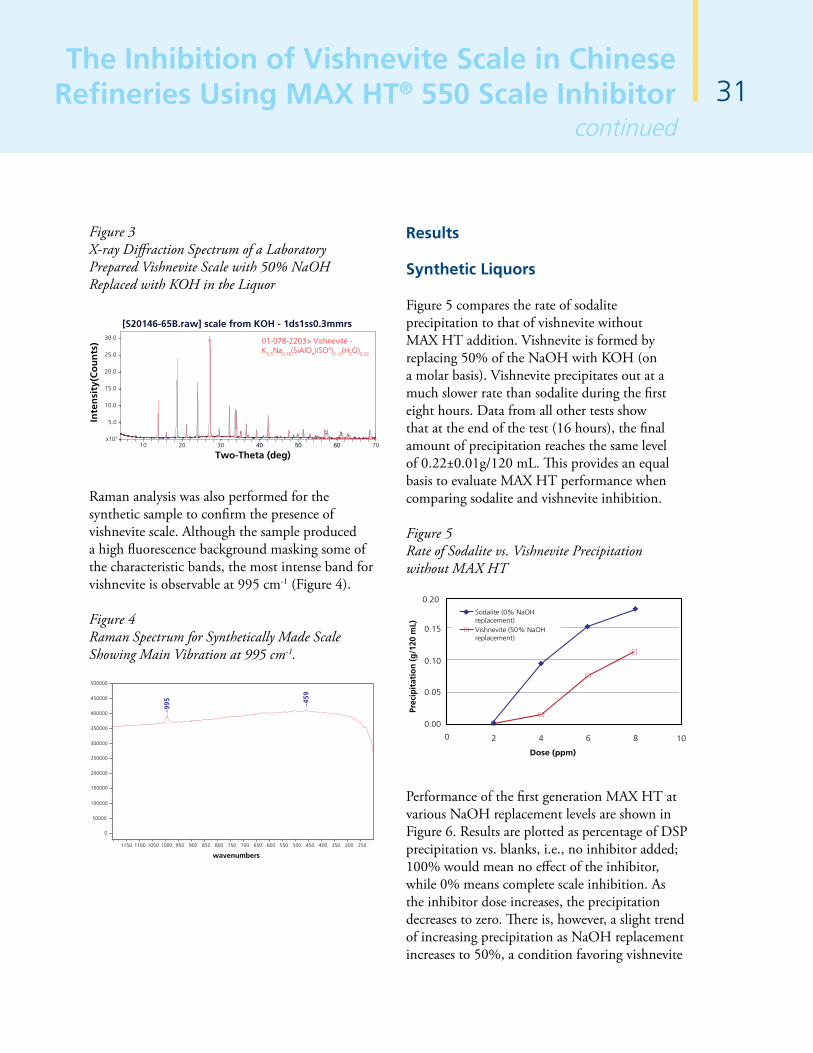
31The Inhibition of Vishnevite Scale in Chinese
Refineries Using MAX HT® 550 Scale Inhibitorcontinued
Figure 3 X-ray Diffraction Spectrum of a Laboratory Prepared Vishnevite Scale with 50% NaOH Replaced with KOH in the Liquor
10 20 30 40 50 60 70x103
5.0
10.0
15.0
20.0
25.0
30.0
Inte
nsi
ty(C
ou
nts
)
[S20146-65B.raw] scale from KOH - 1ds1ss0.3mmrs
01-078-2203> Vishnevite - K0.5Na0.76(SiAlO4)(SO4)0.13(H2O)0.33
Two-Theta (deg)
Raman analysis was also performed for the synthetic sample to confirm the presence of vishnevite scale. Although the sample produced a high fluorescence background masking some of the characteristic bands, the most intense band for vishnevite is observable at 995 cm-1 (Figure 4).
Figure 4 Raman Spectrum for Synthetically Made Scale Showing Main Vibration at 995 cm-1.
500000
450000
400000
995 45
9
350000
300000
250000
200000
150000
100000
50000
1150 1100 1050 1000 950 900 850 800 750 700
wavenumbers
650 600 550 500 450 400 350 300 250
0
Results
Synthetic Liquors
Figure 5 compares the rate of sodalite precipitation to that of vishnevite without MAX HT addition. Vishnevite is formed by replacing 50% of the NaOH with KOH (on a molar basis). Vishnevite precipitates out at a much slower rate than sodalite during the first eight hours. Data from all other tests show that at the end of the test (16 hours), the final amount of precipitation reaches the same level of 0.22±0.01g/120 mL. This provides an equal basis to evaluate MAX HT performance when comparing sodalite and vishnevite inhibition.
Figure 5 Rate of Sodalite vs. Vishnevite Precipitation without MAX HT
Dose (ppm)
Prec
ipit
atio
n (g
/120
mL)
0
0.00
0.05
0.10
0.15
0.20
2 4 6 8 10
Vishnevite (50% NaOH replacement)
Sodalite (0% NaOH replacement)
Performance of the first generation MAX HT at various NaOH replacement levels are shown in Figure 6. Results are plotted as percentage of DSP precipitation vs. blanks, i.e., no inhibitor added; 100% would mean no effect of the inhibitor, while 0% means complete scale inhibition. As the inhibitor dose increases, the precipitation decreases to zero. There is, however, a slight trend of increasing precipitation as NaOH replacement increases to 50%, a condition favoring vishnevite

32The Inhibition of Vishnevite Scale in Chinese Refineries Using MAX HT® 550 Scale Inhibitorcontinued
formation. In contrast, MAX HT 550 displays the opposite trend (Figure 7) with significantly improved inhibition at higher NaOH replacement by KOH.
Figure 6 Performance of First Generation MAX HT
Dose (ppm)
Pre
cip
itati
on
(%
of
bla
nk)
0
0
20
40
60
80
100
5 10 15 20
25% NaOH replacement50% NaOH replacement
No NaOH replacement
Figure 7 Performance of First Generation MAX HT 550
Dose (ppm)
Pre
cip
ita
tio
n (
% o
f b
lan
k)
0
0
20
40
60
80
100
1 2 3 4 5 6
25% NaOH replacement
50% NaOH replacement
0% NaOH replacement
Figure 8 compares the two generations of MAX HT in vishnevite inhibition tests using liquors with 25% and 50% NaOH replacement by KOH. The results show that MAX HT 550 is superior to the first generation in terms of vishnevite
inhibition. It can also be observed from Figures 6 and 8 that the first generation MAX HT, although effective on both types aluminosilicate scales, requires higher dosages to inhibit vishnevite formation than sodalite formation (No NaOH replacement).
Figure 8 Comparison of First Generation MAX HT and MAX HT 550
Dose (ppm)
Prec
ipit
atio
n (
% o
f b
lan
k)
0
0
20
40
60
80
100
5 10 15 20 25
MAX HT 550 25% NaOHreplacementMAX HT 50% NaOHreplacementMAX HT 550 50% NaOHreplacement
MAX HT 25% NaOHreplacement
Plant Liquors
MAX HT was also tested in laboratories at a number of refineries where evaporator scales are identified as vishnevite. Two comparative examples are displayed in Figures 9 and 10. One example was performed using feed liquor to the 1st Effect of the evaporator at Refinery K (Figure 9) and the other example was performed using spent liquor of Refinery L (Figure 10). Consistent with previous test work, MAX HT 550 demonstrates superior vishnevite inhibition relative to the first generation product.
One should not expect that the difference in dosages required of the two generation products will be the same as those required in a plant. The important point from the results
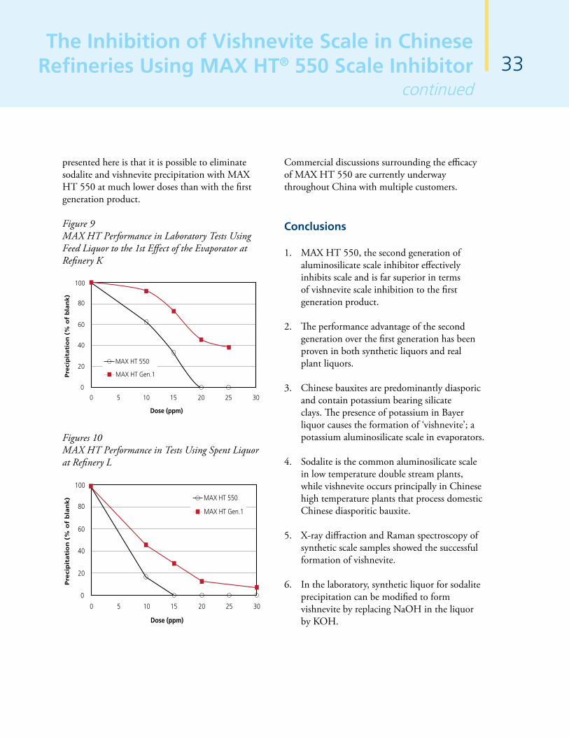
33The Inhibition of Vishnevite Scale in Chinese
Refineries Using MAX HT® 550 Scale Inhibitorcontinued
presented here is that it is possible to eliminate sodalite and vishnevite precipitation with MAX HT 550 at much lower doses than with the first generation product.
Figure 9 MAX HT Performance in Laboratory Tests Using Feed Liquor to the 1st Effect of the Evaporator at Refinery K
Dose (ppm)
Pre
cip
itati
on
(%
of
bla
nk)
0
0
20
40
60
80
100
5 10 15 20 25 30
MAX HT 550
MAX HT Gen.1
Figures 10 MAX HT Performance in Tests Using Spent Liquor at Refinery L
Dose (ppm)
Pre
cip
ita
tio
n (
% o
f b
lan
k)
0
0
20
40
60
80
100
5 10 15 20 25 30
MAX HT 550
MAX HT Gen.1
Commercial discussions surrounding the efficacy of MAX HT 550 are currently underway throughout China with multiple customers.
Conclusions
1. MAX HT 550, the second generation of aluminosilicate scale inhibitor effectively inhibits scale and is far superior in terms of vishnevite scale inhibition to the first generation product.
2. The performance advantage of the second generation over the first generation has been proven in both synthetic liquors and real plant liquors.
3. Chinese bauxites are predominantly diasporic and contain potassium bearing silicate clays. The presence of potassium in Bayer liquor causes the formation of ‘vishnevite’; a potassium aluminosilicate scale in evaporators.
4. Sodalite is the common aluminosilicate scale in low temperature double stream plants, while vishnevite occurs principally in Chinese high temperature plants that process domestic Chinese diasporitic bauxite.
5. X-ray diffraction and Raman spectroscopy of synthetic scale samples showed the successful formation of vishnevite.
6. In the laboratory, synthetic liquor for sodalite precipitation can be modified to form vishnevite by replacing NaOH in the liquor by KOH.

34The Inhibition of Vishnevite Scale in Chinese Refineries Using MAX HT® 550 Scale Inhibitorcontinued
References
1. Spitzer, D., Rothenberg, A., Heitner, H., Kula, F., Lewellyn, M., Chamberlain, O., Dai, Q. and Franz, C., Reagents for the elimination of sodalite scaling, Light Metals (2005), pp 183-188.
2. Spitzer, D., Rothenberg, A., Heitner, H., Kula, F., Lewellyn, M., Chamberlain, O., Dai, Q. and Franz, C., A real solution to sodalite scaling problems, Proceedings of the 7th International Alumina Quality workshop (2005), pp 153-157.
3. Oliveira, A., Dutra, J., Batista, J., Lima, J., Diniz, R. and Repetto, E., Performance appraisal of evaporation system with scale inhibitor application in Alunorte plant, Light Metals (2008), pp 133-136.
4. Spitzer, D., Rothenberg, A., Heitner, H. and Kula, F., Method of preventing or reducing aluminosilicate scale in a Bayer process, U.S. patent 6,814,873 (2004).
5. Spitzer, D., Chamberlain, O., Franz, C., Lewellyn, M. and Dai, Q., MAX HT™ sodalite scale inhibitor: Plant experience and impact on the process, Light Metals (2008), pp 57-62.
6. Riffaud, J.P., James, P.D., Allen, E. and Murray, J.P., Evaluation of sodalite scaling inhibitor – A user’s perspective, International Symposium on Alumimum: From Raw Materials to Applications – Combining Light Metals 2006 and the 17th International ICSOBA Symposium, Montreal, Canada, Oct. 1-4, 2006, Bauxite and Alumina Session, paper 29.7.
7. Spitzer, D., Rothenberg, A., Heitner, H. and Kula, F., Polymers for preventing or reducing aluminosilicate scale in a bayer process, U.S. patent 7,442,755 (2008).
8. Lewellyn, M., Patel, A., Spitzer, D., Franz, C., Ballentine, F., Dai, Q., Chamberlain, O., Kula, F. and Chen, H., MAX HT 500: A second generation sodalite scale inhibitor, Proceedings of the 8th International Alumina Quality workshop (2008), pp 121-124.
9. Gu, S., Chinese bauxite and its influences on alumina production in China, Light Metals (2008), pp 79-83.
10. Li, W., Liu, J., Liu, Z. and Wang, Y., The most important sustainable development issues of Chinese alumina industry, Light Metals (2008), pp 191-195.
11. Bi, S. (Ed.), Process of alumina production, Chemical Industry Press, Beijing, China (2007), p.69 (Chinese).
12. W. Deer, R. Howie, J. Zussman, Rock Forming Minerals, Vol. 4, Longman, Green and Co. LTD, Ppp 289-295, 310-315

Contact Us
Corporate Headquarters
Cytec Industries Inc.Five Garret Mountain PlazaWoodland Park, NJ 07424 USATel: +1 973 357-3193US Toll Free: +1 800 652-6013Fax: +1 973 357-3117
North American Regional Office
Cytec Industries Inc.2085 E. Technology CircleSuite 102Tempe, AZ 85284 USATel: +1 480 730-2000Fax: +1 480 730-2245
South AmericanRegional Office
Los Orfebres 305La Reina, Santiago, ChileTel: +56 2-560-7901Tel: +56 2-560-7900Fax: +56 2-273-6423
Europe, Africa and theMiddle East Regional Office
Cytec Industries BV38, Franko Str., Of. 4Kiev, 01030UkraineTel: +380-44-2302093Fax: +380-44-2386076
Asia PacificRegional Office
Australia Regional Office
Cytec Australia Holdings Pty Ltd.Suite 1, Level 1, Norwest Quay21 Solent CircuitBaulkham Hills, NSW 2153AUSTRALIA Tel: +61 2-9846-6200Fax: + 61 2-9659-9776
China Regional Office
30A Junyao International Plaza789 Zhao Jia Bang Road,Xuhui DistrictShanghai 200032Tel: +86-21-6422-8920Fax: +86-21-6422-8980
Manufacturing Sites
Research Centers
Rayong, Thailand: Emulsions,Flocculants, Blending
Werndorf, Austria: CGM
Botlek, Netherlands:Dewatering aids
Bradford, UK
Australia:Collectors, Blending
Santiago, Chile
Antofogasta, Chile:Collectors, Blending and Warehousing
Houston, TX: CollectorsFrothers
Atlanta, GA: CGM, Collectors
Mobile, AL: Emulsions
Mt Pleasant, TN: Extractants
Willow Island, WV: Collectors,Dewatering Aids
Stamford, CT
Welland, Canada: Collectors,Extractants
Australia: Emulsions
Longview,WA:Emulsions
Phoenix, AZ
Atequiza, Mexico: Collectors, Anti-Scale
Manufacturing Sites
Research Centers
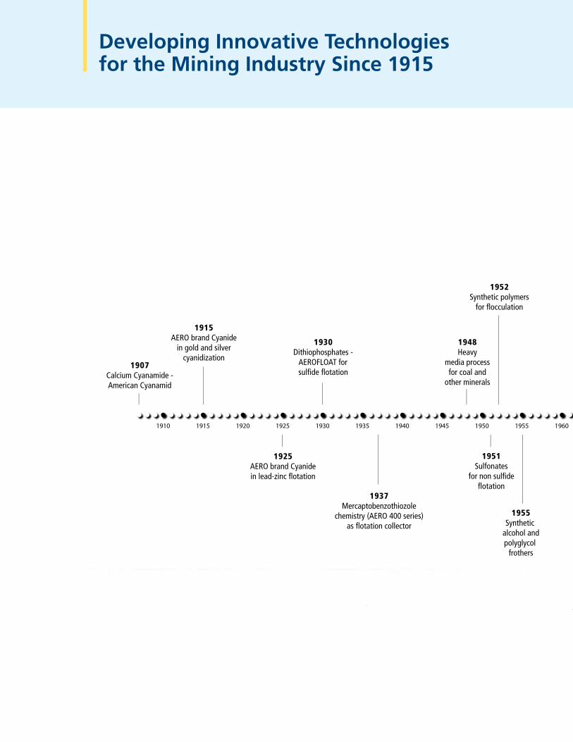
Developing Innovative Technologiesfor the Mining Industry Since 1915
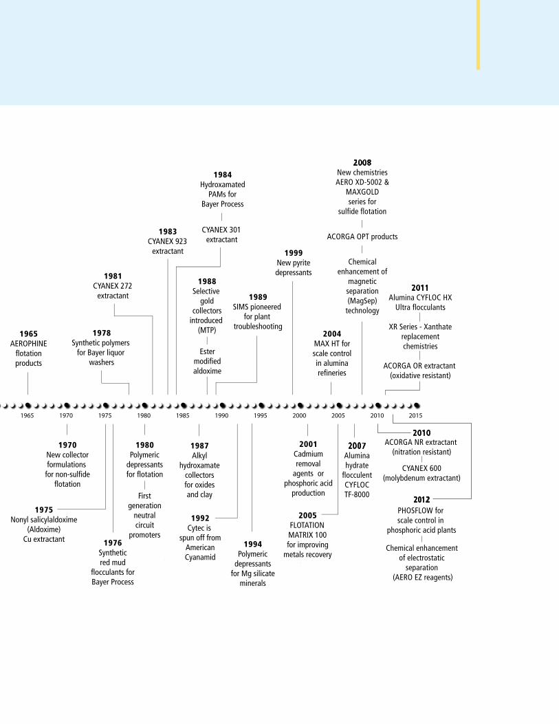

Disclaimer: Cytec Industries Inc. in its own name and on behalf of its affiliated companies (collectively, “Cytec”) decline any liability with respect to the use made by anyone of the information contained herein. The information contained herein represents Cytec’s best knowledge thereon without constituting any express or implied guarantee or warranty of any kind (including, but not limited to, regarding the accuracy, the completeness or relevance of the data set out herein). Nothing contained herein shall be construed as conferring any license or right under any patent or other intel-lectual property rights of Cytec or of any third party. The information relating to the products is given for information purposes only. No guarantee or warranty is provided that the product and/or information is adapted for any specific use, performance or result and that product and/or information do not infringe any Cytec and/or third party intellectual property rights. The user should perform its own tests to determine the suitability for a particular purpose. The final choice of use of a product and/or information as well as the investigation of any possible violation of intellectual property rights of Cytec and/or third parties remains the sole responsibility of the user.
TRADEMARK NOTICE: The ® indicates a Registered Trademark in the United States and the ™ or * indicates a Trademark in the United States. The mark may also be registered, the subject of an application for registration or a trademark in other countries.
* Superfloc is a registered trademark of Kemira OYJ
© 2012 Cytec Industries Inc. All rights reserved
www.cytec.com
MCT-02-A-EN-WW-02D