cylinders iso 6431 vdma - az...
TRANSCRIPT

Cylinders ISO 6431 VDMA
269
MaterialsBarrel: aluminiumPiston-rod: C45 (chromium plated) or stainless steelEnd-cups: aluminiumPiston: technopolymer (standard) or aluminium (on request) - see table on next page Seals: polyurethane or VITONPiston-rod seals: polyurethane or VITONMagnet: magnetic iron compound (not suitable for temperatures over +60°C)
• Compliant to norm ISO 6431 VDMA
• High reliability and long lifetime
• Standard magnetic version
• With square profile (N series) or “easy” profile (E series)
• Special versions and strokes on request
Fluid
Bores 32; 40; 50; 63; 80; 100; 125; 160; 200; 250; 320 mm
Strokes standard: 25 ... 1000 mm; on request up to 3000 mm
ø160-320 : round profile with tie-rods
Construction type ø32 ... 125 : square aluminium profile
Pneumatic cushoning Standard on the whole range
Temperature range standard (poliuretano/NBR): -15+60°C (5-140° F) VITON: max +110°C (230° F)
Operating pressure max 10 bar (145 PSI)max 1 MPa
50µ filtered, lubricated or non lubricated air
Cylinders ISO 6431 VDMA
270
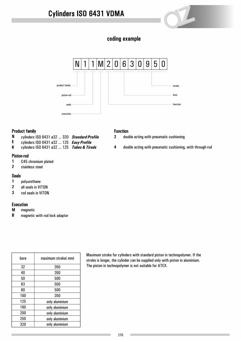
coding example
Product familyN cylinders ISO 6431 ø32 ... 320 Standard ProfileE cylinders ISO 6431 ø32 ... 125 Easy Profile
Piston-rod1 C45 chromium plated 2 stainless steel
Seals1 polyurethane2 all seals in VITON 3 rod seals in VITON
ExecutionM magnetic B magnetic with rod lock adaptor
Function2 double acting with pneumatic cushioning
4 double acting with pneumatic cushioning, with through-rod
bore
32 35040 35050 50063 50080 500
100 350125 only aluminium
only aluminium only aluminium only aluminium only aluminium
160200250320
maximum stroke (mm) Maximum stroke for cylinders with standard piston in technopolymer. If the stroke is longer, the cylinder can be supplied only with piston in aluminium. The piston in technopolymer is not suitable for ATEX.
product family
piston-rod
seals
execution
stroke
bore
function
K cylinders ISO 6431 ø32 ... 125 Tubes & Tirods

Cylinders ISO 6431 VDMA
available versions
stroke
bore
25 X X X X X X X
25 X X X X X X X50 X X X X X X X X X75 X X X X X X X80 X X X X X X X X X
100 X X X X X X X X X125 X X X X X X X150 X X X X X X X X X160 X X X X X X X X X200 X X X X X X X X X250 X X X X X X X X X300 X X X X X X X X X320 X X X X X X X X X350 X X X X X X X400 X X X X X X X X X450 X X X X X X X500 X X X X X X X X X550 X X X X X X X600 X X X X X X X X X650 X X X X X X X700 X X X X X X X X X750 X X X X X X X800 X X X X X X X X X850 X X X X X X X900 X X X X X X X X X950 X X X X X X X
1000 X X X X X X X X X
50 X X X X X X X X X X X75 X X X X X X X80 X X X X X X X X X
100 X X X X X X X X X X X125 X X X X X X X150 X X X X X X X X X160 X X X X X X X X X200 X X X X X X X X X X X250 X X X X X X X X X300 X X X X X X X X X X X320 X X X X X X X X X350 X X X X X X X400 X X X X X X X X X X X450 X X X X X X X500 X X X X X X X X X X X550 X X X X X X X600 X X X X X X X X X X X650 X X X X X X X700 X X X X X X X X X X X750 X X X X X X X800 X X X X X X X X X X X850 X X X X X X X900 X X X X X X X X X X X950 X X X X X X X
1000 X X X X X X X X X X X
32 40 50 63 80 100 125 160 200 250(**)
320(**) double acting
magnetic
with pneumatic cushioning
seals material
polyuret. all seals in VITON rod seals in VITON
piston-rod material
C45 chromium plated
C45 chromium plated
stainless steel
OPTIONS
The standard is marked with grey background
stroke
bore32 40 50 63 80 100 125 160 200 250 320
seals material
polyuret. all seals in VITON rod seals in VITON
piston-rod material
OPTIONS
The standard is marked with grey background
double acting
magnetic
with pneumatic cushioning
through-rod
rod lock adaptor
not available for bores 160-320
rod lock adaptor
not available for bores 160-320
stainless steel
271

Cylinders ISO 6431 VDMA
272
1.He
xago
nal r
od n
ut
12.P
iston
lip
seal
: poly
uret
hane
or V
ITON
14.O
-Ring
hea
d s
eal:
NBR
o VI
TON
15.C
ompa
ss ro
d lo
ckin
g: U
NI 5
105
mat
eria
l 35S
Mn
Pb 1
0, zi
nc p
late
d16
.Rod
: C45
chr
omiu
m p
late
d st
eel o
r sta
inles
s st
eel A
ISI 3
0417
.Fro
nt h
ead:
alu
min
ium
allo
y di
e-ca
stin
g18
.Pist
on w
ith o
give:
tech
nopo
lym
er19
.Mag
net:
mag
netic
iron
com
poun
d20
.O-R
ing p
iston
sea
l: NB
R or
VIT
ON21
.Hea
d as
sem
blin
g sc
rew
: self
-thre
adin
g til
l bor
e 63
, the
n no
rmal
to ta
p22
.Rea
r hea
d: a
lum
iniu
m a
lloy
die-
cast
ing
23.B
arre
l: pr
ofile
d, c
alibr
ated
, ano
dized
alu
min
ium
the drawing is valid from bore 32 to bore 125 - PISTON IN TECHNOPOLYMER
6
3.Pi
ston
-rod
seal
: poly
uret
hane
or V
ITON
4.Gu
ide
bush
ing:
self
-lubr
icatin
g m
ater
ial
5.Pr
otec
tion
plat
e: M
OPLE
N6.
Ring
for c
ushi
onin
g sc
rew
: nick
eled
bras
s7.
Cush
ioni
ng s
crew
: nick
eled
bras
s8.
O-Ri
ng s
eal f
or c
ushi
onin
g sc
rew
: NBR
or V
ITON
9.Bu
mpe
r: HY
TREL
10.S
eal f
or c
ushi
onin
g: p
olyu
reth
ane
or V
ITON

Cylinders ISO 6431 VDMA
273
1.He
xago
nal r
od n
ut
a maschiare
14.O
-Ring
hea
d se
al: N
BR o
r VIT
ON15
.Com
pass
rod
lock
ing:
UNI
510
5 m
ater
ial
35S
Mn
Pb 1
0, zi
nc p
late
d16
.Rod
: C45
chr
omiu
m p
late
d st
eel o
r sta
inles
s st
eel A
ISI 3
0417
.Fro
nt h
ead:
alu
min
ium
allo
y di
e-ca
stin
g18
.Pist
on: a
lumin
ium
19.M
agne
t: m
agne
tic ir
on c
ompo
und
20.O
-Ring
pist
on s
eal:
NBR
or V
ITON
21.H
ead
asse
mbl
ing
scre
w: s
elf-th
read
ing
till b
ore
63, t
hen
norm
al22
.Rea
r hea
d: a
lum
iniu
m a
lloy
die-
cast
ing
23.B
arre
l: pr
ofile
d, c
alibr
ated
, ano
dized
alu
min
ium
the drawing is valid from bore 32 to bore 125 - PISTON IN ALUMINIUM
6
3.Pi
ston
rod
seal
: pol
yure
than
e or
VIT
ON4.
Guid
e bu
shin
g: s
elf-lu
brica
ting
mat
eria
l5.
Prot
ectio
n pl
ate:
MOP
LEN
6.Ri
ng fo
r cus
hion
ing
scre
w: n
ickele
d br
ass
7.Cu
shio
ning
scr
ew: n
ickele
d br
ass
8.O-
Ring
sea
l for
cus
hion
ing
scre
w: N
BR o
r VIT
ON9.
Bum
per:
HYTR
EL
10.S
eal f
or c
ushi
onin
g: p
olyu
reth
ane
or V
ITON
11.O
give
: alu
min
ium
12.P
iston
lip
seal
: pol
yure
than
e or
VIT
ON13
.Pist
on g
uide
ring
: bro
nze
PTFE

Cylinders ISO 6431 VDMA
274
12.C
ompa
ss ro
d lo
ckin
g13
.Rea
r hea
d: a
lum
iniu
m a
lloy
shell
cas
ting
14.H
ead
asse
mbl
ing
scre
w15
.O-R
ing p
iston
sea
l: NB
R or
VIT
ON16
.Pist
on: a
lumin
ium
17.M
agne
t: m
agne
tic ir
on c
ompo
und
18.T
ie ro
d: st
ainl
ess
stee
l19
.Cus
hion
ing
seal
: poly
uret
hane
or V
ITON
20.F
ront
hea
d: a
lum
iniu
m a
lloy
shell
cas
ting
21.R
od: C
45 c
rom
ium
pla
ted
stee
l or s
tain
less
stee
l AIS
I 304
22.O
-Ring
pist
on k
eepi
ng s
eal:
NBR
or V
ITON
23.B
arre
l: alu
min
ium
, rou
nd tu
be
the drawing is valid for bore 160 and 200
1.He
xago
nal r
od n
ut2.
Stai
nles
s st
eel r
ing
for s
eal f
ixing
3.Pi
ston
rod
seal
: poly
uret
hane
or V
ITON
4.Gu
ide
bush
ing:
sin
tere
d br
onze
5.O-
Ring
hea
d se
al: N
BR o
r VIT
ON6.
Ogiva
: alu
min
ium
7.Pi
ston
lip
seal
: poly
uret
hane
or V
ITON
8.Pi
ston
gui
de ri
ng9.
Safe
ty c
ushi
onin
g rin
g
10.
Cush
ioni
ng s
crew
: bra
ss O
T58
11.
O-Ri
ng s
eal f
or c
ushi
onin
g sc
rew
: NBR
or V
ITON

Cylinders ISO 6431 VDMA
275
ø32 ... 125R
+ s
trok
e
S +
str
oke
F +
stro
ke

Cylinders ISO 6431 VDMA
276
øA
BC
DE
FG
HK
LM
NP
QR
ST
J
50 55
72 72
M36
x2
M36
x2
30 40
M16
M16
260
275
G3/
4”
G3/
4”
50 50
180
220
140
175
40 40
65 75
CH
36
CH
36
65 75
180
180
119
119
CH
55
CH
55
6 6
16
0
20
0
ø160-200
6R +
str
oke
S +
str
oke
F +
stro
ke

Cylinders ISO 6431 VDMA
277
ø250-320R
+ s
trok
e
S +
str
oke
F +
stro
ke
Cylinders ISO 6431 VDMA
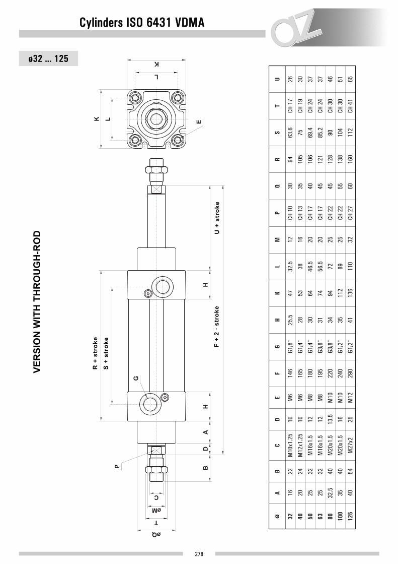
278
VER
SIO
N W
ITH
TH
RO
UG
H-R
OD
ø32 ... 125
6
U+
stro
ke
R +
str
oke
S +
str
oke
F +
2 ∙ s
trok
e

Cylinders ISO 6431 VDMA
279
øA
BC
DE
FG
HK
LM
PQ
RS
TU
50 55
72 72
M36
x2
M36
x2
30 40
M16
M16
340
370
G3/
4”
G3/
4”
50 50
180
220
140
175
40 40
CH
36
CH
36
65 75
180
180
119
119
CH
55
80
CH
55
95
16
0
20
0
ø160-200
6
VER
SIO
N W
ITH
TH
RO
UG
H-R
OD
R +
str
oke
S +
str
oke
U +
str
oke
F +
2 ∙ s
trok
e

Cylinders ISO 6431 VDMA
280
Seals Kit
MAGNETIC, standard seals
normal
for bore
32
40
50
63
32 SGM032P 21.110.2
40 SGM040P 21.111.2
50 SGM050P 21.112.2
63 SGM063P 21.113.2
80 80 SGM080P 21.114.2
100 100 SGM100P 21.115.2
125 125 SGM125P 21.116.2
160 160 SGM160P 21.117.2
200 200 SGM200P 21.118.2
SGM032 21.100.2
SGM040 21.101.2
SGM050 21.102.2
SGM063 21.103.2
SGM080 21.104.2
SGM100 21.105.2
SGM125 21.106.2
SGM160 21.107.2
SGM200 21.108.2
part number code for bore part number code
passing-through rod
MAGNETIC, VITON seals
normal
for bore
32 SGM032V 21.120.2
40 SGM040V 21.121.2
50 SGM050V 21.122.2
63 SGM063V 21.123.2
80 SGM080V 21.124.2
100 SGM100V 21.125.2
125 SGM125V 21.126.2
160 SGM160V 21.127.2
200 SGM200V 21.128.2
part number code
passing-through rod
for bore
32 SGM032PV 21.130.2
40 SGM040PV 21.131.2
50 SGM050PV 21.132.2
63 SGM063PV 21.133.2
80 SGM080PV 21.134.2
100 SGM100PV 21.135.2
125 SGM125PV 21.136.2
160 SGM160PV 21.137.2
200 SGM200PV 21.138.2
part number code

281
21.191.2
21.192.2
21.193.2
21.194.2
21.195.2
21.196.2
40
50
63
80
100
125
52
code A
63
73
92
110
134
38
B
46.5
56.5
72
89
110
20.5
C
25.5
21.5
31
31
33
27
D
32
28
38
38
44
6.5
21.190.2 32 46 32.5 21.5 27 6.5
E
8.5
8.5
10.5
10.5
12.5
for bore
Intermediate flange for opposite ISO 6431 cylinders
This intermediate flange has to be inserted between two ISO 6431 VDMA cylinders to form an opposite cylinder. It is sold in kit with all necessary pieces for installation.
Assembling instructions
Cylinders ISO 6431 VDMA

Cylinders ISO 6431 VDMA
282
cylinder kit
MAGNETIC, standard seals
normal
for bore
32 KSM032 21.001.3
40 KSM040 21.002.3
50 KSM050 21.003.3
63 KSM063 21.004.3
32 KSM032P 21.011.3
40 KSM040P 21.012.3
50 KSM050P 21.013.3
63 KSM063P 21.014.3
80 KSM080 21.005.3 80 KSM080P 21.015.3
100 KSM100 21.006.3 100 KSM100P 21.016.3
125 KSM125 21.007.3 125 KSM125P 21.017.3
160 KSM160 21.008.3 160 KSM160P 21.018.3
200 KSM200 21.009.3 200 KSM200P 21.019.3
part number code for bore part number code
through-rod
MAGNETIC, VITON seals
normal
for bore
32 KSM032V 21.021.3
40 KSM040V 21.022.3
50 KSM050V 21.023.3
63 KSM063V 21.024.3
80 KSM080V 21.025.3
100 KSM100V 21.026.3
125 KSM125V 21.027.3
160 KSM160V 21.028.3
200 KSM200V 21.029.3
part number code
through-rod
for bore
32 KSM032PV 21.031.3
40 KSM040PV 21.032.3
50 KSM050PV 21.033.3
63 KSM063PV 21.034.3
80 KSM080PV 21.035.3
100 KSM100PV 21.036.3
125 KSM125PV 21.037.3
160 KSM160PV 21.038.3
200 KSM200PV 21.039.3
part number code
The kit contains:
- Pre mounted heads with bushing, bumper and cushioning- Piston with magnet, seals and guide ring (for aluminium piston)- Ogive- Screws- Protection plates- All necessary seals

Cylinders ISO 6431 VDMA
283
cylinder kit assembly instructions
INSTRUCTIONS TO USE ISO 6431 ASSEMBLING CYLINDER KIT
All components contained in this ISO 6431 assembling pneumatic cylinder kit are manufactured with first quality materials. In order to ensure consistent quality and to respect accurate dimensional tolerances, die-cast heads and all internal components are lathes' and numerical control work centres' machine worked. The cylinder is designed and built to offer high performances also in the hardest work conditions. To ensure constant quality, the assembly has to be executed according to the instructions reported below. All safety standards have to be respected during installation and cylinder testing.
1. PRELIMINARY OPERATIONS
Before assembling, blow with compressed air and clean accurately surfaces, all components and the barrel previously cut to the desired length. The cylinder has to be installed in a clean and dustless work environment.
2. ASSEMBLE PISTON ON THE ROD
Insert the following components in this order on the rod (Refer to image 1): ogive, semi-piston, O-Ring seal, attracting magnets , semi-piston, ogive. Before screwing, put on the rod thread one or two drops of threadlocker. Screw the nut on the rod respecting the torque given in the following table:
3. INSERT THE LOCK ROD-PISTON IN THE BARREL
With an appropriate grease (eventually purchasable from AZ Pneumatica) lubricate lightly the barrel inside, piston seals and heads seals. Position the guide ring in teflon-copper (available only for aluminium pistons), lubricated with grease, around the piston (see image 2); insert the lock rod-piston, previously assembled, in the barrel paying attention to not damage the piston seals (see image 3). To simplify this operation, it is possible to purchase a specific adaptor from AZ Pneumatica.
bore
32 10 Nm40 20 Nm50 30 Nm63 45 Nm80 60 Nm
100 60 Nm125 70 Nm
7 Nm9 Nm
15 Nm19 Nm27 Nm35 Nm
-160-200 80 Nm -
aluminium piston technopolymer piston
torque
image 1
image 2
image 3
Cylinders ISO 6431 VDMA
284
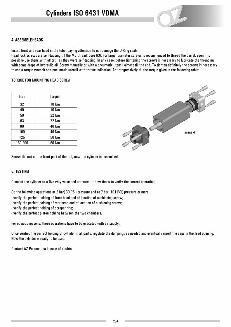
4. ASSEMBLE HEADS
Insert front and rear head in the tube, paying attention to not damage the O-Ring seals. Head lock screws are self-tapping till the M8 thread (bore 63). For larger diameter screws is recommended to thread the barrel, even if is possibile use them ,with effort, as they were self-tapping. In any case, before tightening the screws is necessary to lubricate the threading with some drops of hydraulic oil. Screw manually or with a pneumatic utensil almost till the end. To tighten definitely the screws is necessary to use a torque wrench or a pneumatic utensil with torque indication. Act progressively till the torque given in the following table:
TORQUE FOR MOUNTING HEAD SCREW
Screw the nut on the front part of the rod, now the cylinder is assembled.
5. TESTING
Connect the cylinder to a five way valve and activate it a few times to verify the correct operation.
Do the following operations at 2 bar (30 PSI) pressure and at 7 bar (101 PSI) pressure or more . - verify the perfect holding of front head and of location of cushioning screw;- verify the perfect holding of rear head and of location of cushioning screw;- verify the perfect holding of scraper ring;- verify the perfect piston holding between the two chambers.
For obvious reasons, these operations have to be executed with air supply.
Once verified the perfect holding of cylinder in all parts, regulate the dampings as needed and eventually insert the caps in the feed opening. Now the cylinder is ready to be used.
Contact AZ Pneumatica in case of doubts.
bore
32 10 Nm40 10 Nm50 22 Nm63 22 Nm80 40 Nm
100 40 Nm125 50 Nm
160-200 60 Nm
torque
image 4

STANDARD profile for N series
Barrel for cylinders ISO 6431 VDMA
285
dimensions [mm]weight[kg/m]
2.198
order code
000.510.7
000.511.7
000.512.7
A B C D
ø32 H11 32.5 44.5 17
2.506ø40 H11 38 50.5 23
3.394ø50 H11 46.5 60.3 26
E
-
-
-
000.513.7 3.452ø63 H11 56.5 70 37 35
000.514.7
000.515.7
5.214ø80 H11 72 87 45 45
5.619ø100 H12 89 106 50 46
000.516.7 7.788ø125 H12 110 132 56 50
chemical composition Cu
≤ 0.10Fe
≤ 0.35Mn
≤ 0.10Mg
0.45÷0.90Si
0.20÷0.60Zn
≤ 0.10Cr
≤ 0.10Ti
≤ 0.10Al
rest
Fixing holes
from ø32 to ø63 : prepared for metric thread through rolling or self-tapping screws
from ø80 to ø125 : prepared for metric thread through rolling
Round profile for cylindersø160: 000.517.7ø200: 000.518.7

Barrel for cylinders ISO 6431 VDMA
286
dimensions [mm]weight[kg/m]
1.407
order code
000.530.7
000.531.7
000.532.7
A B C D
ø32 H11 36 32.5 44.4
1.644ø40 H11 44 38 51
2.035ø50 H11 54 46.5 60.8
E
13±0.2
18.8±0.2
22.4±0.25
000.533.7 2.312ø63 H11 67 56.5 70.9 32.6±0.3
000.534.7
000.535.7
2.877ø80 H11 84 72 87 41±0.3
3.873ø100 H12 104.5 89 105.5 53±0.3
000.536.7 5.316ø125 H12 130 110 131 64±0.35
øA
C
C
E
øB
D
D
chemical composition Cu
≤ 0.10Fe
≤ 0.35Mn
≤ 0.10Mg
0.45÷0.90Si
0.20÷0.60Zn
≤ 0.10Cr
≤ 0.10Ti
≤ 0.10Al
rest
Fixing holes
from ø32 to ø63 : prepared for metric thread through rolling or self-tapping screws
from ø80 to ø125 : prepared for metric thread through rolling
EASY profile for E series
6

Fixing elements for cylinders ISO 6431 VDMA
287
CMSS032
CMSS040
CMSS050
CMSS063
CMSS080
CMSS100
CMSS125
CMSS160
CMSS200
32
40
50
63
80
100
125
160
200
45
part number A
52
65
75
95
115
140
180
220
32.5
B
38
46.5
56.5
72
89
110
140
175
30
C
35
40
45
45
55
60
65
75
10.5
D
12
15
15
18
18
25
28
28
22
E
25
27
32
36
41
50
55
60
16
F
19
21
24
28.5
30
40
45
48
9
H
9
11
11
14
14
20
20
25
ø11
J
ø11
ø15
ø15
ø18
ø18
ø20
ø26
ø26
5
L
5
5
5
5
5
7
7
7
10
M
12
16
16
20
20
30
35
35
14
N
16
21
21
25
25
37
43
43
5.5
P
5.5
6.5
6.5
10
10
10
10
11
6.6
Q
6.6
9
9
11
11
13.5
18
18
for bore
NARROW MALE HINGE WITH ARTICULATED HEAD DIN 648K

Fixing elements for cylinders ISO 6431 VDMA
288
MALE HINGE MP4
CMIS032
CMIS040
CMIS050
CMIS063
CMIS080
CMIS100
CMIS125
CMIS160
CMIS200
32
40
50
63
80
100
125
160
200
32.5
part number
CMKS032
CMKS040
CMKS050
CMKS063
CMKS080
CMKS100
CMKS125
CMKS160
CMKS200
part number
standard with bronze bushingA
38
46.5
56.5
72
89
110
140
175
26
B
28
32
40
50
60
70
90
90
22
C
25
27
32
36
41
50
55
60
6.6
D
6.6
9
9
11
11
14
18
18
5
F
5
5
5
5
5
7
7
7
9
G
9
11
11
14
14
20
20
25
45
L
52
65
75
95
115
140
180
220
10
M
12
12
16
16
20
25
30
30
5.5
N
5.5
6.5
6.5
10
10
10
10
11
11
R
11
15
15
18
18
20
26
26
30
S
35
40
45
45
55
60
65
75
10
T
12
12
16
16
20
25
25
25
for bore
Fixing elements for cylinders ISO 6431 VDMA
289
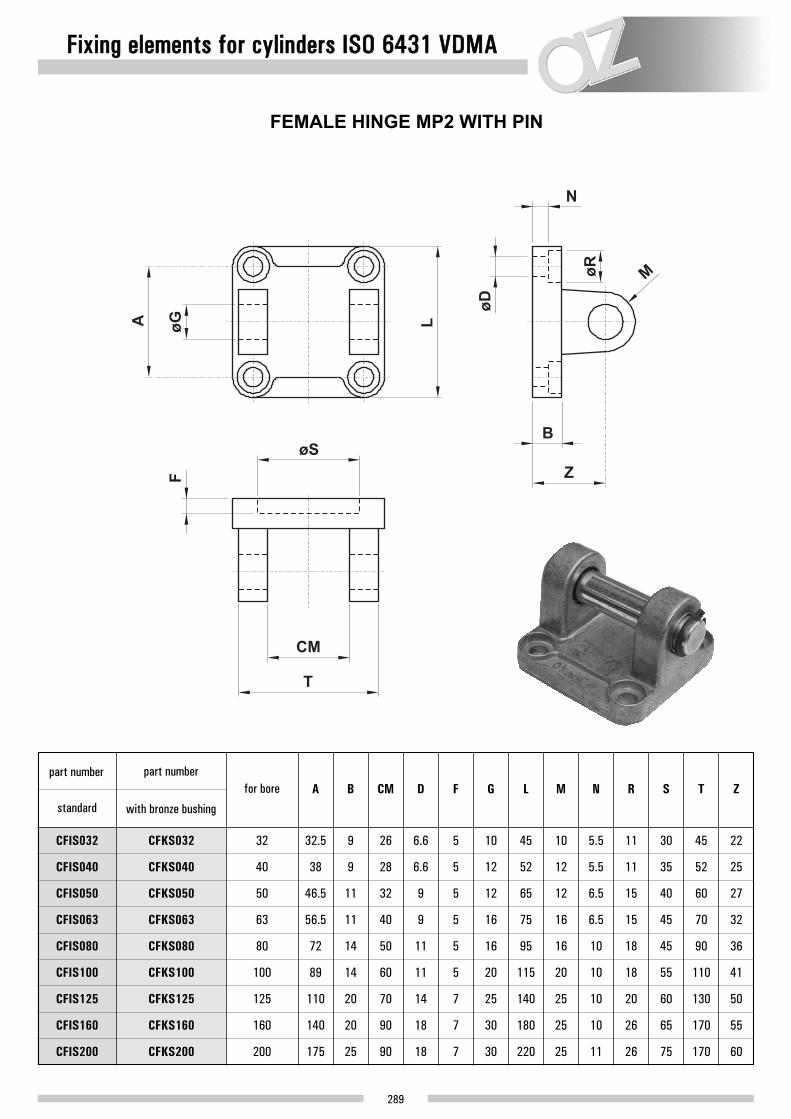
FEMALE HINGE MP2 WITH PIN
CFIS032
CFIS040
CFIS050
CFIS063
CFIS080
CFIS100
CFIS125
CFIS160
CFIS200
32
40
50
63
80
100
125
160
200
32.5
part number
CFKS032
CFKS040
CFKS050
CFKS063
CFKS080
CFKS100
CFKS125
CFKS160
CFKS200
part number
standard with bronze bushing
A
38
46.5
56.5
72
89
110
140
175
9
B
9
11
11
14
14
20
20
25
26
CM
28
32
40
50
60
70
90
90
6.6
D
6.6
9
9
11
11
14
18
18
5
F
5
5
5
5
5
7
7
7
10
G
12
12
16
16
20
25
30
30
45
L
52
65
75
95
115
140
180
220
10
M
12
12
16
16
20
25
25
25
5.5
N
5.5
6.5
6.5
10
10
10
10
11
11
R
11
15
15
18
18
20
26
26
30
S
35
40
45
45
55
60
65
75
45
T
52
60
70
90
110
130
170
170
22
Z
25
27
32
36
41
50
55
60
for bore

Fixing elements for cylinders ISO 6431 VDMA
290
FLANGE
FLIS032
FLIS040
FLIS050
FLIS063
FLIS080
FLIS100
FLIS125
FLIS160
FLIS200
32
40
50
63
80
100
125
160
200
80
part number A
90
110
120
150
170
205
260
300
45
B
52
65
75
95
115
140
180
220
10
C
10
12
12
16
16
20
20
25
32.5
D
38
46.5
56.5
72
89
110
140
175
64
E
72
90
100
126
150
180
230
270
32
F
36
45
50
63
75
90
115
135
ø30
G
ø35
ø40
ø45
ø45
ø55
ø60
ø65
ø75
6.6
H
6.6
9
9
11
11
13.5
18
18
10.5
J
11
15
15
18
18
20
26
26
7
L
9
9
9
12
14
16
18
22
6.5
M
6.5
8.5
8.5
10.5
10.5
12.5
16.5
16.5
for bore

Fixing elements for cylinders ISO 6431 VDMA
291
PBIS032
PBIS040
PBIS050
PBIS063
PBIS080
PBIS100
PBIS125
PBIS160
PBIS200
32
40
50
63
80
100
125
160
200
7
part number* A
9
9
9
12
14
16
18
22
32
B
36
45
50
63
71
90
115
135
35
C
36
47
45
55
57
70
75
100
4
D
4
5
5
6
6
8
9
12
24
E
28
32
32
41
41
45
60
70
15.75
F
17
21.75
21.75
27
26.5
35
45
47.5
7
G
7
9
9
11
11
14
18
18
30
H
30
36
35
47
53
70
100
100
15
J
17.5
20
22.5
22.5
27.5
30
32.5
37.5
32.5
K
38
46.5
56.5
72
89
110
140
175
32
L
36
45
50
63
75
90
115
135
45
M
52
65
75
95
115
140
180
220
for bore
FOOT MOUNTING
* Part number refers to a single element, not to the couple
6

Fixing elements for cylinders ISO 6431 VDMA
292
CIN032
CIN040
CIN050
CIN063
CIN080
CIN100
32
40
50
63
80
100
87
part number A
105
117
136
156
195
65
B
74.8
90.3
94.5
109.3
134
44.5
C
50.5
60.3
70.5
87.5
106.6
52
D
62
74
91
111
129
17.5
E
21.5
21.5
22.5
22.5
33
12
G
16
16
20
20
25
45
H
51
60.8
70
87
106
25
J
25
25
30
30
40
CIN125 125 223 160 132.6 157 33 25 132 40
2
K
2.5
2.5
2.5
2.5
2.5
2.5
for bore
INTERMEDIATE TRUNNION - ONLY FOR ''N'' SERIES
bores: 32, 40, 50
bores: 63, 80, 100, 125

Fixing elements for cylinders ISO 6431 VDMA
293
SNINT 032 B
SNINT 040-050 B
SNINT 063-080 B
SNINT 100-125 B
32
40-50
63-80
100-125
46
part number* A
55
65
75
30
B
35
40
50
15
C
20
20
30
10.5
D
14
17
19
6.5
E
9
11
14
ø12
F
ø16
ø20
ø25
6.5
G
8
12
10
7.5
H
10
10
15
32
J
36
42
50
for bore
SUPPORT FOR INTERMEDIATE TRUNNION
* Part number refers to a couple of elements

Fixing elements for cylinders ISO 6431 VDMA
294
CSIS160TI
CSIS200TI
160
200
part number A
200
250
B
32
32
C
ø171
ø211
D
140
175
E
M16
M16
G
ø32
ø32
H
190
240
J
40
40
L
190
240
for bore
FIXED INTERMEDIATE TRUNNION for cylinders bores 160 and 200
tie-rods version
This intermediate trunnion can be mounted only on a cylinder with round barrel and tie-rods. The request for cylinders with tie-rods must be clearly specified on the order. On the order please specify also the position where the fixing element should be mounted on the cylinder.
6

Fixing elements for cylinders ISO 6431 VDMA
295
26.327.2N
26.328.2N
160
200
part number A
140
175
AE
190
240
AL
40
40
AH
ø32
ø32
AG
32
32
AF
200
250
AN
ø171
ø211
M
ø16.25
ø16.25
Q
18
18
Z
M12
M12
for bore
ADJUSTABLE INTERMEDIATE TRUNNIONfor cylinders bores 160 and 200
tie-rods version
This intermediate trunnion can be mounted only on a cylinder with round barrel and tie-rods.ATTENTION: This adjustable intermediate trunnion, even if it is correctly mounted on the cylinder, because of the weight can move and cause very serious injury. To avoid this it is better to use a fixed intermediate trunnion!

Fixing elements for cylinders ISO 6431 VDMA
296
RECTANGULAR JOINTCETOP RP107P NORM
COIS032
COIS040
COIS050
COIS063
COIS080
COIS100
32
40
50
63
80
100
26
part number A
28
32
40
50
60
COIS125 125
COIS160
COIS200
70
160 90
200 90
20
B
22
26
30
30
38
45
63
63
6.6
C
6.6
9
9
11
11
14
14
18
10
D
12
12
16
16
20
25
30
30
38
E
41
50
52
66
76
94
118
122
18
F
22
30
35
40
50
60
88
90
32
G
36
45
50
63
71
90
115
135
31
H
35
45
50
60
70
90
126
130
51
J
54
65
67
86
96
124
156
162
21
L
24
33
37
47
55
70
97
105
8
M
10
12
14
14
17
20
25
30
10
N
15
16
16
20
20
30
36
40
11
Q
11
15
15
18
18
20
20
26
1.6
T
1.6
1.6
1.6
2.5
2.5
3.2
4
4
for bore
Fixing elements for cylinders ISO 6431 VDMA
297
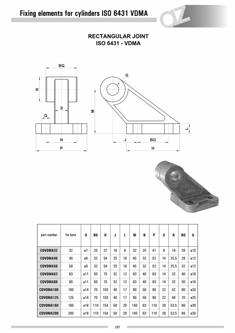
RECTANGULAR JOINTISO 6431 - VDMA
COVDMA32
COVDMA40
COVDMA50
COVDMA63
COVDMA80
COVDMA100
32
40
50
63
80
100
ø7
part number Q
ø9
ø9
ø11
ø11
ø14
COVDMA125 125
COVDMA160
COVDMA200
ø14
160 ø18
200 ø18
20
BG
32
32
50
50
70
70
110
110
37
H
54
54
75
75
103
103
154
154
18
J
25
25
32
32
40
40
50
50
8
L
10
10
12
12
17
17
20
20
32
M
45
45
63
63
90
90
140
140
25
N
32
32
40
40
50
50
63
63
41
P
52
52
63
63
80
80
110
110
9
S
14
14
14
14
22
22
26
26
19
R
25.5
25.5
32
32
42
46
53.5
53.5
26
BQ
28
32
40
50
60
70
89
89
ø10
G
ø12
ø12
ø16
ø16
ø20
ø25
ø30
ø30
for bore

Fixing elements for cylinders ISO 6431 VDMA
298
NARROW FEMALE HINGE FOR JOINT WITH ARTICULATED HEAD DIN 648K
CMTA
T
AL
A
L
D3
B
H
Z
øS
D1
F
D2
TZ
LJ
MR
G
CFSIS032
CFSIS040
CFSIS050
CFSIS063
CFSIS080
CFSIS100
32
40
50
63
80
100
45
part number L
52
65
75
95
115
CFSIS125 125
CFSIS160
CFSIS200
140
160 180
200 220
34
T
40
45
51
65
75
97
122
122
14
CM
16
21
21
25
25
37
43
43
32.5
A
38
46.5
56.5
72
89
110
140
175
22
Z
25
27
32
36
41
50
55
60
5
H
5
5
5
5
5
7
7
7
9
B
9
11
11
14
14
20
20
25
5.5
D3
5.5
6.5
6.5
10
10
10
10
11
30
S
35
40
45
45
55
60
65
75
ø10
G
ø12
ø16
ø16
ø20
ø20
ø30
ø35
ø35
10
MR
12
14
18
20
22
25
30
30
ø6.6
D1
ø6.6
ø9
ø9
ø11
ø11
ø14
ø18
ø18
ø11
D2
ø11
ø15
ø15
ø18
ø18
ø20
ø26
ø26
3
TA
4
4
4
4
4
6
6
6
3.3
TZ
4.3
4.3
4.3
4.3
6.3
6.3
6.3
6.3
11.5
LJ
12
14
14
16
16
24
26.5
26.5
17
F
20
22
25
30
32
42
46
49
for bore

Fixing elements for cylinders ISO 6431 VDMA
299
32 142
ø A
22
B
10
C
2
D
4
E
32
F
24
G
142
H
7
J
11
K
40 160 25 12 2 4 36 28 161 9 8
50 170 27 12 5 5 45 32 170 9 15
63 190 32 16 5 5 50 32 185 9 13
80 210 36 16 5 6 63 41 210 12 14
100 230 41 20 10 6 75 41 220 14 16
125 275 50 25 20 8 90 45 250 16 25
160 315 55 30 20 9 115 60 300 18 15
200 335 60 30 25 12 135 70 320 22 30
CMIS...
CMKS...
CMSS...
PBIS...
MALE TRUNNION
FEMAL TRUNNION WITH PIN
FOOT MOUNT
BALL-JOINT MALE TRUNNION
CFIS...
CFKS...
A + stroke
A + stroke
A + stroke
H + stroke

Fixing elements for cylinders ISO 6431 VDMA
300
32 130
ø A
16
B
7
C
32
E
64
F
52
H
87
J
65
L
12
M
25
N
40 145 20 9 36 72 62 105 74.8 16 25
50 155 25 9 45 90 74 117 90.3 16 25
63 170 25 9 50 100 91 136 94.5 20 30
80 190 30 12 63 126 111 156 109.3 20 30
100 205 35 14 75 150 129 195 134 25 40
125 245 45 16 90 180 156.7 222.7 160 25 40
160 280 60 18 115 230 190 262 200 32 40
200 300 70 22 135 270 240 312 250 32 40
FLIS...FLANGE
INTERMEDIATE TRUNNION PER ESTRUSO - ONLY FOR "N" SERIES CIN...
CSIS...TI
A + stroke

Accessories for cylinders
301
FORKS
FR8C10
FR12C16
FRC20
FR25C32
FRC40
FR50C63
FR80C100
FRC125
FR160C200
8-10
12-16
20
25-32
40
50-63
80-100
125
160-200
M4x0.7 4 8 ø4 ø8 6 21 16 8 clip
part number d a b d1 d2 L1e L n supplied with
M6x1 6 12 ø6 ø10 9 31 24 12 clip
M8x1.25 8 16 ø8 ø14 12 42 32 16 clip
M10x1.25 10 20 ø10 ø18 15 52 40 20 clip
M12x1.25 12 24 ø12 ø20 18 62 48 24 clip
M16x1.5 16 32 ø16 ø26 24 83 64 32 clip
M20x1.5 20 40 ø20 ø34 30 105 80 40 clip
M27x2 30 55 ø30 ø48 38 148 110 54 pin
M36x2 35 70 ø35 ø60 40 188 144 72 pin
for bores
6

Accessories for cylinders
302
CLIPS FOR FORKS
PINS FOR FORKS
used for forkcode
M4x0.726.119.0
26.120.0
26.121.0
26.122.0
26.123.0
26.124.0
26.125.0
M6x1
4
6
8
12
11
16
9
14
19
28
15
23
n A Bd1 L1 L2L
5
6
M8x1.25 8 16 22 19 37 31 8
M10x1.25 10 20 26 23 46 39 10
M12x1.25 12 24 32 28 55 47 12
M16x1.5 16 32 40 36 72 62 14
M20x1.5 20 40 48 44 88 72 16
used for fork
M27x2
M36x2
d
30
35
65 28.6
84 33.4
55
70
3.4
5.4
1.6
1.6
L d1 L1 a b
NUTS FOR PISTON-ROD
DSIS032X
DSIS040X
DSIS05063X
DSIS080100X
DSIS125X
DSIS160200X
26.196.2
26.197.2
26.198.2
21.750.0
21.751.0
21.752.0
21.753.0
21.754.0
21.755.0
8-10DSMC8-10
DSMC12-16
DSMC20
DSIS032
DSIS040
DSIS05063
DSIS080100
DSIS125
DSIS160200
STANDARDpart number
STAINLESS STEELpart number for bore
12-16
20
25-32
40
50-63
80-100
125
160-200
M4x0.7
thread
M6x1
M8x1.25
M10x1.25
M12x1.25
M16x1.5
M20x1.5
M27x2
M36x2
7
key
10
13
17
19
24
30
41
55
code

TS8T10X
TS12T16X
TST20X
TS25T32X
TST40X
TS50T63X
TS80T100X
TST125X
TS160T200X
8-10
12-16
20
25-32
40
50-63
80-100
125
160-200
M4x0.7 ø5 8 6 18 ø11 27 10 36 4 10TS8T10
TS12T16
TST20
TS25T32
TST40
TS50T63
TS80T100
TST125
TS160T200
STANDARDpart number
STAINLESS STEELpart number
d3 d B L4 L5 L7L3C1 d2 d5 h1
M6x1 ø6 9 6.75 20 ø13 30 12 40 5 11
M8x1.25 ø8 12 9 24 ø16 36 16 48 5 13
M10x1.25 ø10 14 10.5 28 ø19 43 20 57 6.5 15
M12x1.25 ø12 16 12 32 ø22 50 22 66 6.5 17
M16x1.5 ø16 21 15 42 ø27 64 28 85 8 23
M20x1.5 ø20 25 18 50 ø34 77 33 102 10 27
M27x2 ø30 37 25 70 ø50 110 51 145 15 36
M36x2 ø35 43 28 80 ø58 125 56 165 17 41
9
W
11
14
17
19
22
30
41
50
for bores
Accessories for cylinders
303
SWIVEL BALL JOINT
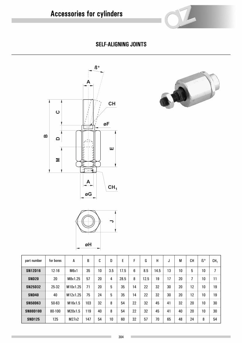
SN12D16
SND20
SN25D32
SND40
SN50D63
SN80D100
12-16
20
25-32
40
50-63
80-100
M6x1 35 10 3.5 17.5 6 8.5 14.5 13 10
part number A B C D E F G H J M
M8x1.25 57 20 4 28.5 8 12.5 19 17 20
M10x1.25 71 20 5 35 14 22 32 30 20
M12x1.25 75 24 5 35 14 22 32 30 20
M16x1.5 103 32 8 54 22 32 45 41 32
M20x1.5 119 40 8 54 22 32 45 41 40
5
CH
7
12
12
20
20
10
ß°
10
10
10
10
10
7
CH1
11
19
19
30
30
SND125 125 M27x2 147 54 10 60 32 57 70 65 48 24 8 54
for bores
Accessories for cylinders
304
SELF-ALIGNING JOINTS

Accessories for cylinders
PISTON ROD PROTECTION COVERS
305
Piston rod protection cover for ISO 6431 VDMA cylinders, in double-sided hyped-up cloth (fabric). Water, oil and dust resistant. Colour: blue.The protection cover must be fixed on the piston rod by two clamps, not provided with the protection cover.
If the cylinder stroke is longer than the value in this table, we advise to increase the dimension D of the piston rod length (refer to pages 414-415) by 1.1 mm for each winding.
Example: a cylinder bore 80 and stroke 300 needs 24 windings. It is necessary to increase the piston rod length by (24–12) x 1.1 mm = 13.2 mm. The cylinder with longer piston rod must be ordered as special (please contact the commercial office).
for cylinder ø A B number of windings for 100 mm stroke size identification
32; 40 30
40
55
70
60
80
130
155
C
36
46
40
55
50; 63; 80 8
100; 125 4
160; 200 3
10 A
B
C
D
110 180 60250; 320 3 E
SO A 1 0
number of windingssize identification
winding thickness in compressed state
n : number of windings
bore
32 9040 9050 13063 13080 140
100 330125 550
8701170
99
11111214222736
160200
maximum stroke (mm) corresponding number of windings

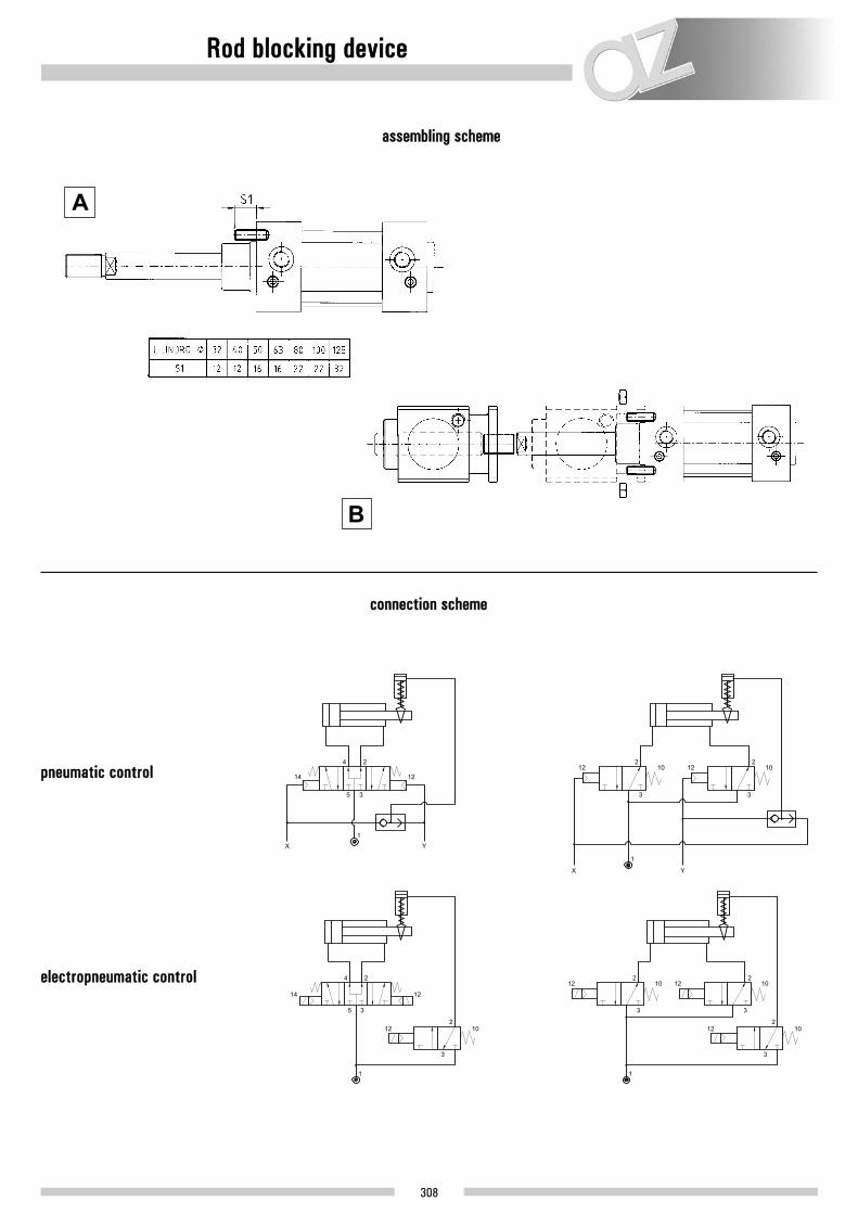
Rod blocking device
306
MaterialsBody: aluminium (anodize treatment) Internal parts: brassPistons: polymerSprings: steel
Fluid
Construction type Mechanical bi-directional
Locking force 200
12ø
force (N)
16 20 25 32 40 50 63 80 100 125
200 490 490 790 1240 1930 3060 5400 7700 12040
Function NC (pneumatic piloted unlock)
Temperature range -15+60°C (5-140° F
Minimum actuating pressure 3 bar (43.5 PSI)
0.3 MPa
50µ filtered, lubricated or non lubricated air
The rod blocking device can be used with cylinders ISO 6431 VDMA (bores from 32 to 125) and with minicylinders ISO 6432 (bores from 12 to 25).The device is normally locked. It is unlocked by applying a pneumatic signal. Therefore it is possible to block the cylinder in case of pressure drop or to stop the movement in intermediate positions.

version for cylinders ISO 6431
32BM032
BM040
BM050
BM063
BM080
BM100
BM125
40
50
32.5 47 6 67.5 M6 30 26
A B C G H WH
38 54 6 80 M6 35 30
46.5 65 8
22.5
D F
20
24 100 M8 40 32
G1/8”
N
G1/8”
G1/8”
33.5
P
42.5
58
9.5
Q
10.5
12.5
8
R
8
12
86
S
100
122
60
E
70
90
63 56.5 75 8 24 100 M8 45 37 G1/8” 59 17.5 12 12790
80 72 95 12 32 120 M10 45 46 G1/4” 69 17.5 16 156110
100 89 114 12 32 120 M10 55 51 G1/4” 69 27 16 161110
125 110 140 20 45 156 M12 60 65 G1/4” 84.5 20 20 205140
for borespart number
Rod blocking device
307
version for minicylinders ISO 6432
12-16BM012
BM020
BM025
20
25
30 29.5 10.5 17 22 24.5 4
A B C G H L
35 33.5 13 22 24 26.5 4.5
35 33.5 13
44.5
D F
54
54 22 28 26.5 4.5
M5
M
M5
M5
M16x1.5
E
M22x1.5
M22x1.5
for boresmodel
Rod blocking device
308
assembling scheme
connection scheme
A
B
pneumatic control
electropneumatic control

Guide units
309
MaterialsBody: aluminium (anodize treatment) Rods: C40 (chromium plated)
• Guide units for cylinders ISO 6431 and minicylinders ISO 6432
• Available versions: type “U” with sintered bronze rod guide (code UB...) - cylinder bores from 12 to 100type “H” with sintered bronze rod guide (code HB...) - cylinder bores from 12 to 100type “H” with linear ball bearings (code HS...) - cylinder bores from 12 to 100
• Type “U” with sintered bronze rod guide: movements with medium loads and low speeds
• Type “H” with sintered bronze rod guide: movements with heavy loads and low speeds
• Type “H” with linear ball bearings: movements with medium loads and high speeds
TypeH “H” typeU “U” type
Rod guide B sintered bronzeS linear ball bearings
stroke
bore
50 X
12*16*
X
X
X
X
X
20
X
X
X
X
X
25
X
X
X
X
X
32
X
X
X
X
X
X
X
40
X
X
X
X
X
X
X
50
X
X
X
X
X
X
X
63
X
X
X
X
X
X
100
150
160
200
250
300
400
X X X X
X
80
X
X
X
X
X
X
X
X
100
X
X
X
X
X
X
X500
coding example available bores and strokes
* The guide unit for bore 12 is used also for bore 16, with thesame code.
type
rod guide
stroke
cylinder bore

Guiding units
310

Guiding units
311
ø CIL
1216
A
30
20 34
25 34
A1
27
32
32
B
65
79
79
B1
63
76
76
C
38
48
48
C1
10
12
12
CH
8
12
12
CZ
19
27
27
D
4
6
6
E
15
20
20
E1
32
40
40
E2
54
68
68
E3
6.5
8.5
8.5
E4
24
38
38
E5
25
32.5
32.5
E6
22
23
23
F
M4
M6
M6
H
15
20
20
F1
M4
M5
M5
F2
8.5
10.5
10.5
F3
5.1
6.5
6.5
F4
7.5
9
9
F5
4.5
5.5
5.5
G
12
22
17
I
46
58
58
L
70
83
83
L1
53
60
71
76
M
51
65
65
N
13
17
17
P
5.5
6.5
6.5
S
8
10
10

Guiding units
312
ø CIL
32
A
48 45 100 90 48 12 32.5 32.5 78 58 M6 6.5 20 31 74 106 94 54 17 7.8 7.8 12 13 48
40 56 50 106 105 58 12 38 38 84 64 M6 6.5 22 36 80 117 105 55 21 10 10 12 15 54
50 66 60 125 124 59 15 46.5 46.5 100 80 M8 9 23 45 96 129 106 68 25 6.3 6.3 16 21 67
63 76 70 132 125 76 15 56.5 56.5 105 95 M8 9 23 45 104 146 121 68 25 9.8 9.8 16 21 76
80 98 90 165 155 90 18 72 50 130 130 M10 11 30 56 130 170 128 78 34 20 9 20 27 97
100 118 110 185 175 110 18 89 70 150 150 M10 11 30 56 150 190 138 78 39 20 10.5 20 27 117
A1 B B1 C C1
6
6
6
6
6
6
D E E1 E2 E3 F F1 G H I L L1 M N O O1 S CH U1

Guiding units
313
ø CIL
1216
A
30
20 34
25 34
A1
27
32
32
B
65
79
79
B1
63
76
76
C
75
108
108
C1
10
12
12
CH
8
12
12
CZ
19
27
27
D
4
6
6
E
15
20
20
E1
32
40
40
E2
54
68
68
E3
6.5
8.5
8.5
E4
24
38
38
E5
32.5
32.5
32.5
E6 E7
22
23
23
11
15
15
F
M4
M6
M6
H
15
20
20
F1
M4
M5
M5
F2
8.5
10.5
10.5
F3
5.1
6.5
6.5
F4
7.5
9
9
F5
4.5
5.5
5.5
G
12
22
17
I
46
58
58
L
130
159
159
L1
53
60
71
76
M
51
65
65
P
5.5
6.5
6.5
S
8
10
10
U
37
58
58

Guiding units
314
ø CIL
32
A
97
40 115
50 137
63 152
80 189
100 213
A1
90
105
124
145
180
200
B
50
58
70
85
105
130
B1
45
50
60
70
100
120
C
125
136
144
176
215
220
C1
12
12
15
15
20
20
CH
13
15
21
21
27
27
D
6
6
6
6
6
6
E
32.5
38
46.5
56.5
72
89
E1
78
84
100
105
130
150
E2
4.3
11
18.5
15.3
21
24.5
E3
61
69
85
100
130
150
F
M6
M6
M8
M8
M10
M10
F1
6.5
6.5
9
9
11
11
G
20
22
23
23
30
30
H
31
36
45
45
56
56
I
74
87
104
119
148
173
L
177
192
237
237
280
280
L1
94
105
106
121
128
138
M
54
55
68
68
78
78
N
17
21
26
26
34
39
S
12
16
20
20
25
25
U
76
81
79
111
128
128
U1
50.5
58.5
70.5
85.5
106
131
6

Guiding units
315
guide units kit
“U” type with sintered bronze rod guide
for bore
12-16 KUB012-016 27.271.0
20 KUB020 27.272.0
25 KUB025 27.273.0
32 KUB032 27.274.0
40 KUB040 27.275.0
50 KUB050 27.278.0
63 KUB063 27.279.0
80 KUB080 27.280.0
100 KUB100 27.281.0
part number code
“H” type with sintered bronze rod guide
for bore
12-16 KHB012-016 27.259.0
20 KHB020 27.250.0
25 KHB025 27.251.0
32 KHB032 27.252.0
40 KHB040 27.253.0
50 KHB050 27.254.0
63 KHB063 27.255.0
80 KHB080 27.256.0
100 KHB100 27.257.0
part number code
“H” type with linear ball bearings
for bore
12-16 KHS012-016 27.260.0
20 KHS020 27.261.0
25 KHS025 27.268.0
32 KHS032 27.262.0
40 KHS040 27.263.0
50 KHS050 27.264.0
63 KHS063 27.265.0
80 KHS080 27.266.0
100 KHS100 27.267.0
part number code
Kit includes all necessary pieces. Rods are not included. The drawing for rod machining is available on:http://www.azpneumatica.com/azweb/ita/kitguid.htm
6