cylinder and seal kit replacement · pdf filecylinder and seal kit replacement guide ......
TRANSCRIPT

Cylinder and Seal Kit Replacement Guide
PB 10-4Rev. C 7.29.2010
© July 2010 by Rotary Lift. All rights reserved.

2
TABLE OF CONTENTS
*Cylinder Trouble Shooting on “SP” Series Lifts .........................................................3
*Assembly Instructions For Kit #FJ7375 ........................................................................5
*FJ592 Cylinder Bleeder Replacement Kit ....................................................................6
*Exploded View of Cylinder (Sample) ............................................................................7
*2-Post Cylinder Manufacturers Guide .........................................................................7
2-Post Cylinder Guide .......................................................................................................8
4-Post Cylinder Guide ......................................................................................................12
Low/Mid Rise Cylinder Guide .........................................................................................17
Rolling Jack Cylinder Guide ............................................................................................20
*NOTE: Pages 3-7 describe 2-Post cylinders but may be applied to other cylinder types shown in booklet.

3
Cylinder Trouble Shooting On “SP” Series Lifts 1) Customer complaint: Fluid leaking and/or accumulating around base of lift. 2) Possible causes: A) Oil on floor due to causes other than leaks at lift. B) Fitting at base of cylinder leaking. C) Manual bleeder leaking. D) Cylinder leaking from seal. E) Leaks oil from breather. F) Hose leaking or weeping.
How to Check Hydraulic System 1) Clean all oil points. 2) Raise lift all the way up and hold it under pressure for 10 seconds. 3) Relieve pressure at lowering valve. 4) Check all possible leak points. 5) If leaks are found, determine the extent of repair needed.
If The Cylinder Is leaking From Seal***Before removing cylinder make sure you have the correct seal kit.***
Double “S” Formed Column Lifts.Cylinder Removal Procedure 1) Loosen the equalizer cable on the opposite carriage. 2) Raise the lift to the top and rest the carriage on the top latch position. 3) Check to make sure the carriage is secure on latches. 4) Make sure the pressure has been relieved from the system. 5) Follow the proper LOCKOUT/TAGOUT procedures for disconnecting power to lift. 6) Remove the lower sheave cover at base of column. 7) With lowering valve depressed, manually pull cylinder down out of carriage. 8) Disconnect the swivel hose fitting at base of cylinder. 9) Cap hose ends and cylinder adapter to prevent fluid loss. 10) Carefully remove cylinder from column.
Cylinder Rebuilding***Kit has only enough parts for (1) cylinder.*** 1) Remove manual bleeder and extend plunger from casing. 2) Remove piston retaining ring or clip. 3) Remove plunger from casing. 4) Clean inside of casing, making sure all debris is removed with mineral spirits. 5) Inspect seal for damage. 6) Replace seal and all other components (wiper, wear ring, etc.). 7) Coat seal with oil or white grease. 8) Reinstall plunger, retaining ring, and manual bleeder being careful not to scratch or dent plunger surface.
Cylinder Replacement 1) Reinstall cylinder and reconnect hose fitting. 2) Reconnect power source. 3) Install lower sheave cover. 4) Raise cylinder in column through the carriage lifting plate and cylinder centering bar. 5) Lower both carriages. 6) Adjust equalizer cables. 7) Carefully raise carriages about two feet. Bleed air from both cylinders. 8) Fully lower lift. 9) Check and add fluid as necessary. 10) Raise lift to full rise and check for leaks. 11) Tag lift back in service.

4
SP84, SPOA84, SP94, Series Lifts
Cylinder Removal Procedure 1) Raise the lift about 2’-0”. Open manual bleeder in top of both cylinders to bleed off any air pockets. Close bleeder
when fluid appears. Lower lift. 2) Remove arm pins and swing arms. 3) Disconnect both cables at upper tie-off. 4) Manually lift carriage to its top locking position. Let carriage rest on latch. Place a suitable support under car-
riage. 5) Remove the upper cable sheave bracket. (Also column extensions on SPO models.) 6) Disconnect hydraulic line and unscrew adapter at the cylinder base. 7) Remove 1/4” x 4-1/2” HHCS at base of cylinder. 8) Manually lift carriage until upper rollers or slider blocks start to protrude above column. 9) Angle cylinder out of column through front opening and lower carriage back in top latch position.
Cylinder Rebuilding 1) Using a spanner wrench or other suitable tool, turn cylinder casing clockwise, until straight end of retainer ring
is located in the mill slot on the cylinder casing. 2) Insert screwdriver under beveled edge of retainer ring. 3) Turn casing head counterclockwise until retainer ring is removed. Note: If cylinder is laying horizontally, place oil pan under cylinder head area before casing head is removed. 4) Remove casing head. 5) Open manual bleeder vent at top of cylinder and remove entire plunger from cylinder casing and inspect for
nicks, scratches, etc. 6) Install new seal kit. 7) Apply a generous coating of Dexron III ATF on new seal kit components. 8) Insert plunger in cylinder, being careful not to scratch finish. 9) Insert cylinder casing head and line up retainer ring slot with mill slot in cylinder casing. 10) Insert bent end of retainer ring into slot. 11) Turn casing head clockwise until retainer ring is completely inside casing. 12) Close the manual bleeder valve.
Cylinder Replacement 1) Install hex adapter on new cylinder. 2) Again, manually lift the carriage and insert cylinder in the column. 3) Lower carriage to top locking latch position. 4) Secure cylinder in column and replace 1/4” bolt. 5) Reinstall upper sheave bracket. 6) Reconnect hydraulic line. 7) Lift carriage off locking latch and position latch arm to disengage the latch. 8) Lower carriage to floor. 9) Reconnect cable to upper cable tie-off. BE SURE cables are roped through sheave rollers. 10) Raise lift about 2’-0” and open manual bleeder in top of cylinder. Close when fluid appears. 11) Remove filler breather cap from power unit and refill reservoir with Dexron III, ATF. 12) Raise lift to full travel and adjust tension on cables. Grasp cables between thumb and forefinger. With about
15lbs. tension, you should just pull the cables together. 13) Tighten cable jam nut on upper cable tie-off stud. 14) Lower lift and reassemble arms and pins. 15) Raise lift to full travel and check pipe joints for leaks. 16) The lift should now be ready for use.
5
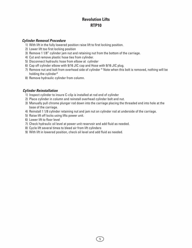
Revolution LiftsRTP10
Cylinder Removal Procedure1) With lift in the fully lowered position raise lift to first locking position.2) Lower lift too first locking position3) Remove 1 1/8” cylinder jam nut and retaining nut from the bottom of the carriage.4) Cut and remove plastic hose ties from cylinder.5) Disconnect hydraulic hose from elbow at cylinder6) Cap off cylinder elbow with 9/16 JIC cap and Hose with 9/16 JIC plug.7) Remove nut and bolt from overhead side of cylinder * Note when this bolt is removed, nothing will be
holding the cylinder*8) Remove hydraulic cylinder from column.
Cylinder Reinstallation1) Inspect cylinder to insure C-clip is installed at rod end of cylinder2) Place cylinder in column and reinstall overhead cylinder bolt and nut.3) Manually pull chrome plunger rod down into the carriage placing the threaded end into hole at the
base of the carriage.4) Reinstall 1 1/8 cylinder retaining nut and jam nut on cylinder rod at underside of the carriage.5) Raise lift off locks using lifts power unit.6) Lower lift to floor level7) Check hydraulic oil level at power unit reservoir and add fluid as needed.8) Cycle lift several times to bleed air from lift cylinders9) With lift in lowered position, check oil level and add fluid as needed.
6
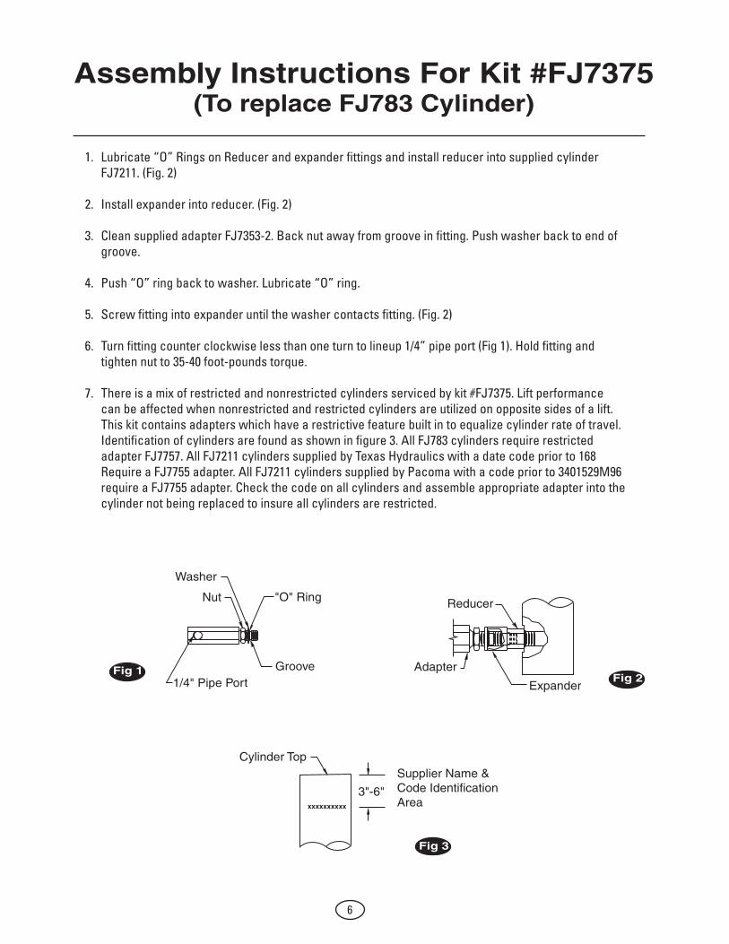
Assembly Instructions For Kit #FJ7375(To replace FJ783 Cylinder)
1. Lubricate “O” Rings on Reducer and expander fittings and install reducer into supplied cylinder FJ7211. (Fig. 2)
2. Install expander into reducer. (Fig. 2)
3. Clean supplied adapter FJ7353-2. Back nut away from groove in fitting. Push washer back to end of groove.
4. Push “O” ring back to washer. Lubricate “O” ring.
5. Screw fitting into expander until the washer contacts fitting. (Fig. 2)
6. Turn fitting counter clockwise less than one turn to lineup 1/4” pipe port (Fig 1). Hold fitting and tighten nut to 35-40 foot-pounds torque.
7. There is a mix of restricted and nonrestricted cylinders serviced by kit #FJ7375. Lift performance can be affected when nonrestricted and restricted cylinders are utilized on opposite sides of a lift. This kit contains adapters which have a restrictive feature built in to equalize cylinder rate of travel. Identification of cylinders are found as shown in figure 3. All FJ783 cylinders require restricted adapter FJ7757. All FJ7211 cylinders supplied by Texas Hydraulics with a date code prior to 168 Require a FJ7755 adapter. All FJ7211 cylinders supplied by Pacoma with a code prior to 3401529M96 require a FJ7755 adapter. Check the code on all cylinders and assemble appropriate adapter into the cylinder not being replaced to insure all cylinders are restricted.
Washer
Nut "O" Ring
1/4" Pipe PortGroove
Reducer
Adapter
Expander
xxxxxxxxxx
Cylinder Top
3"-6"
Supplier Name & Code Identification Area
Fig 1Fig 2
Fig 3

7
XXXXX * T 2 11 XX
3"-6"
FJ592 Cylinder Bleeder Replacement Kit
Installation Instructions
Replace using the correct bleeder screw for the model you have. Use the chart below to determine type of cylinder used. Date codes for identifying can be found using the illustration below.
DAY OF MONTH
MONTH(Nov.)
YEAR(1992)
TEXAS
* DATE CODE
BLEEDER SCREW
TOP OF CYLINDER
Bleeder Screws For Pacoma Cylinders
Bleeder Screws For Texas Hydraulics Cylinders
Part No#. 32516 - Date code T211XX & after (Nov. 92) Consists of: Part No# 32326 Screw & Part No# 14525 O-Ring Washer
Part No#. 3443881 MI - All cylinders used the same screw.

8
1 Adapter 2 Housing 3 Piston Rod 4 Bushing Guide 5 Felt Wiper 6 Felt Ring 7 Seal 8 Guide Ring 9 Retainer Wire 10 Seal 11 Bleeder Plug
2
8 7 6
5
3
9
1
1011
4

9
2-Post Cylinder
Guide
2-Post Cylinder
Guide
PB 10-4-1
10
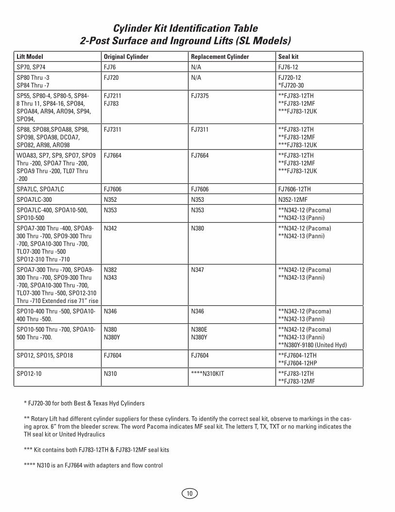
Cylinder Kit Identification Table2-Post Surface and Inground Lifts (SL Models)
* FJ720-30 for both Best & Texas Hyd Cylinders ** Rotary Lift had different cylinder suppliers for these cylinders. To identify the correct seal kit, observe to markings in the cas-ing aprox. 6” from the bleeder screw. The word Pacoma indicates MF seal kit. The letters T, TX, TXT or no marking indicates the TH seal kit or United Hydraulics *** Kit contains both FJ783-12TH & FJ783-12MF seal kits **** N310 is an FJ7664 with adapters and flow control
Lift Model Original Cylinder Replacement Cylinder Seal kit
SP70, SP74 FJ76 N/A FJ76-12
SP80 Thru -3 SP84 Thru -7
FJ720 N/A FJ720-12 *FJ720-30
SP55, SP80-4, SP80-5, SP84-8 Thru 11, SP84-16, SPO84, SPOA84, AR94, ARO94, SP94, SPO94,
FJ7211 FJ783
FJ7375 **FJ783-12TH **FJ783-12MF ***FJ783-12UK
SP88, SPO88,SPOA88, SP98, SPO98, SPOA98, DCOA7, SPO82, AR98, ARO98
FJ7311 FJ7311 **FJ783-12TH **FJ783-12MF ***FJ783-12UK
WOA83, SP7, SP9, SPO7, SPO9 Thru -200, SPOA7 Thru -200, SPOA9 Thru -200, TL07 Thru -200
FJ7664 FJ7664 **FJ783-12TH **FJ783-12MF ***FJ783-12UK
SPA7LC, SPOA7LC FJ7606 FJ7606 FJ7606-12TH
SPOA7LC-300 N352 N353 N352-12MF
SPOA7LC-400, SPOA10-500, SPO10-500
N353 N353 **N342-12 (Pacoma) **N342-13 (Panni)
SPOA7-300 Thru -400, SPOA9-300 Thru -700, SPO9-300 Thru -700, SPOA10-300 Thru -700, TLO7-300 Thru -500 SPO12-310 Thru -710
N342 N380 **N342-12 (Pacoma) **N342-13 (Panni)
SPOA7-300 Thru -700, SPOA9-300 Thru -700, SPO9-300 Thru -700, SPOA10-300 Thru -700, TLO7-300 Thru -500, SPO12-310 Thru -710 Extended rise 71” rise
N382 N343
N347 **N342-12 (Pacoma) **N342-13 (Panni)
SPO10-400 Thru -500, SPOA10-400 Thru -500.
N346 N346 **N342-12 (Pacoma) **N342-13 (Panni)
SPO10-500 Thru -700, SPOA10-500 Thru -700.
N380 N380Y
N380E N380Y
**N342-12 (Pacoma) **N342-13 (Panni) **N380Y-9180 (United Hyd)
SPO12, SPO15, SPO18 FJ7604 FJ7604 **FJ7604-12TH **FJ7604-12HP
SPO12-10 N310 ****N310KIT **FJ783-12TH **FJ783-12MF

11
78 3/8" Retracted
2 3/4"
21 3/8" Retracted89 3/8" Extended
FJ720 Cylinder
77" Retracted
2 5/8"
5 3/4" Retracted73 3/4" Extended
FJ7375 Kit/FJ7211 Cylinder
75 3/8" Retracted
1 3/8"
6 11/16" Retracted74 11/16" Extended
FJ7311 Cylinder
79 15/16" Retracted
1 7/8"
7 3/4" Retracted79 3/4" Extended
FJ7604 Cylinder

12
75 1/4" Retracted
3 1/8"
12 1/2" Retracted80 1/2" Extended
FJ76 Cylinder
77" Retracted
2 5/8"
5 3/4" Retracted73 3/4" Extended
FJ783 Cylinder
48 1/4" Retracted116 1/4" Extended
FJ7606 Cylinder
74" Retracted(Pacoma)
73 3/8" Retracted(Texas Hydraulics)
1 3/8"
6 11/16" Retracted74 11/16" Extended
FJ7664/N310 Cylinder
73.858" Retracted
N380e Cylinder
02-3/8
3.353.00
6 11/16Retracted74 11/16Extended
1877 Ref.(73.9)
N380y Cylinder
170 Ref.(6.7)

13
4-Post Cylinder
Guide
4-Post Cylinder
Guide
PB 10-4-2

14
Cylinder Kit Identification Table4-Post Lifts
How To Determine Cylinder Manufacturer:
x x x x
Clevis
Date/ID Code
Notes:• Lookallthewayaroundthecylindertubeontheclevisorpressureportendformarkings.• TexasHydrauliccylinderswillbeidentifiedbya“TX”followedbyafourdigitdatecodestampedonthe
cylinder. In some cases the Rotary part number will be stamped above the date code.• Pacoma cylinders will have “Pacoma” stamped on them.
Lift Model 992304 Replacement Cylinder Seal kit SM7 S130093 (94" Stroke)
S130095 (77" Stroke)S130093 S130095
S130093-12
SM90, AR90, CWA90, SM91, AR91
FC5343 (Clevis) FC537 (Bracket)
NLA FC537KIT
*FC537-12T *FC537-12MF
SM101 FC5342 FC5797-1 *FC542-12TH *FC542-12MF
SM120, AR120, CWA120, SM121, AR121, QL4P, QLHV
FC5342 (Clevis) FC542 (Bracket)
FC5797-1 FC542-KIT
*FC542-12TH *FC542-12MF
SM122, AR122, SMO123, ARO122, QL4P-100 QLHV-100, SM101-100
FC5797 FC5342
FC5797-1 FC5797-1
FC5797-TH-UNI *FC542-12TH *FC542-12MF
SM123, AR123, SMO123, ARO123, SM12, AR12, QL4P-200, QL12
S130002 S130002 FC5797-TH-UNI **S130002-12HY **S130002-12PC
SM14, AR14, S130002 S130002 FC5797-TH-UNI **S130002-12HY **S130002-12PC
SMO14, ARO14 S130156 S130156 **S130002-12HY **S130002-12PC
SM180, SM181, SM18 FC5810-38 FC5810-38 FC5810-38-12THSM300, SM250, SM270, FLS25 FC5225-15 FC5225-15 FC5225-70SM300, SM500, SM600 FC5761 FC5761 FC5761-12THFLS12, FLS15 FC5155 FC5155 FC5155-1012000LRT (Mez) 992302 992302 992302SKAA40000HDL, 50000HDL 992304 992304 992304SKAA60000HDL 992326 992326Scissor / Parallelogram (Light Duty)ARP70 FC86 NLA FC86-12THGLP35-100 40-0604 (P1 Cyl.)
40-0605 (P2 Cyl.)40-0604 (P1 Cyl.) 40-0605 (P2 Cyl.)
04L7173 (P1) 04L7173 (P2)
SC9i XS130008 XS130008 XS130138YA12 Z140039Y Z140039Y Z140039Y-12Parking LiftVSS7-000 & -010 PS130004 PS130004 *PS100008TH
*PS100008MFVSS7-001 & -011 PS130004 PS130004 *PS100008TH
*PS100008MF
* Rotary Lift had different cylinder suppliers for these cylinders. To identify the correct seal kit, observe to markings in the casing. The word Pacoma indicates MF seal kit. The letters T, TX, TXT or no marking indicates the TH seal kit.
**Hyko Cylinder

15
75-1/4" Retracted135-1/4" Extended
2-1/8"
FC5343 Cylinder
73" Retracted133" Extended
1-1/2"
FC537 Cylinder
74-5/16" Retracted134-5/16" Extended
2-5/16"
FC5797 Cylinder
47-1/4" Retracted80-1/4" Extended
FC5155 Cylinder
83" Retracted143" Extended
5"
FC5761 Cylinder
83" Retracted143" Extended
5"
FC5225-15 Cylinder
16
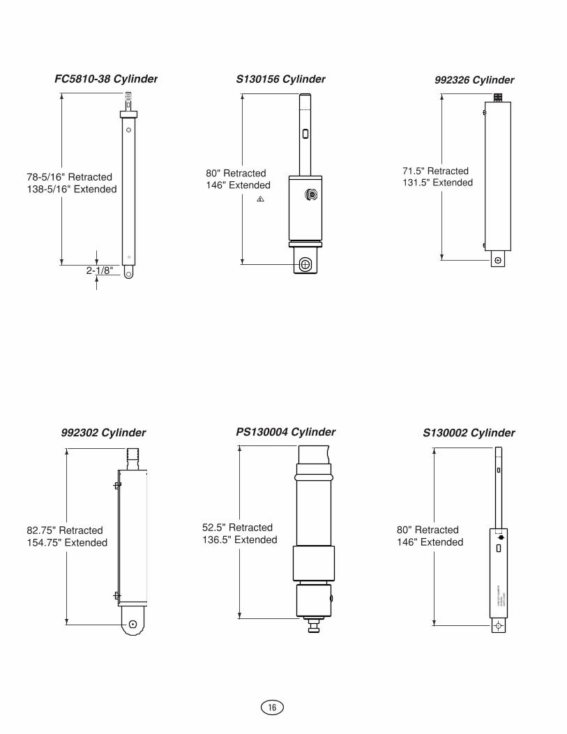
78-5/16" Retracted138-5/16" Extended
2-1/8"
FC5810-38 Cylinder
80" Retracted146" Extended
S130156 Cylinder
71.5" Retracted131.5" Extended
992326 Cylinder
82.75" Retracted154.75" Extended
992302 Cylinder PS130004 Cylinder
52.5" Retracted136.5" Extended
S130002 Cylinder
80" Retracted146" Extended
VE
ND
OR
NU
MB
ER
S13
0002
DA
TE
CO
DE

17
Low/Mid Rise Cylinder
Guide
Low/Mid Rise Cylinder
Guide
PB 10-4-3

18
Cylinder Kit Identification TableLow/Mid Rise
How To Determine Cylinder Manufacturer:•Lookallthewayaroundthecylindertubeontheclevisorpressureportendformarkings.•Texas Hydraulic cylinders will be identified by a “TX” followed by a four digit date code stamped on
the cylinder. In some cases the Rotary part number will be stamped above the date code.•Pacoma cylinders will have “Pacoma” stamped on them.•North Carolina cylinders are stamped “North Carolina”.•Duke cylinders have a snap ring at the rod end.
Seal Replacement:When replacing seals on lift models PAL4 and PAL5 use only seal kit FJ2248-12. All later PAL, MPAL, MPFX, and PFX models can use either seal kit FJ2248-12 or FJ294-3-12.
XXXX
Bracket
ID/DateStamp
Lift Model Original Cylinder Replacement Cylinder Seal kit
PAL4, PAL5E FJ253-3 NLA NLA
PAL-5E FJ294-3 NLA FJ294-3-12MF
PAL7, PFX, MPFX, PSL6, VLX6, VLXS6, VL6, VLS6, VLD6
FJ2248 FJ2248 *FJ2248-12TH *FJ294-3-12MF
PFX-1, PAL6 FJ2173 NLA *FJ2248-12TH *FJ294-3-12MF
MPAL8 FJ2263 FJ2263 *FJ2248-12TH *FJ294-3-12MF
MR6, VM6, VMP6, VMP6A, VMR6
FJ860 FJ860 FJ860-12TH
VLXS7, VLXS10 992305 992305 **991513 (Texas) **992305SKAA (Arlington) **YG42-9180
* Rotary Lift had different cylinder suppliers for these cylinders. To identify the correct seal kit, observe to mark-ings in the casing. The word Pacoma indicates MF seal kit. The letters T, TX, TXT or no marking indicates the TH seal kit.**Used three different cylinder Mfg. Look for markings on the cylinder. If no markings use YG642-9180 seal kit.

19
25-5/8" Retracted43-5/8 " Extended
FJ2248 Cylinder
43-5/8" Retracted79-5/8 " Extended
FJ860 Cylinder
31-5/8" Retracted55-5/8 " Extended
FJ2263 Cylinder
20
Smart Lift Cylinder
Guide
Smart LiftCylinder
Guide
PB 10-4-4

21
Lift Model Original Cylinder Replacement Cylinder Seal kit
SL19 FJ7604 FJ7604 **FJ7604-12TH **FJ7604-12HP
SL28, SL9, SL29 Thru -200 FJ7664 FJ7664 **FJ783-12TH **FJ783-12MF
SL29-300 N342 N380
N380 N380
**N342-12 (Pacoma) **N342-13 (Panni)
SL29-400 Thru -800 SL212-400 Thru 1000
N367 N367 N342-12
** Need to ID cylinder for correct kit
79 15/16" Retracted
1 7/8"
7 3/4" Retracted79 3/4" Extended
FJ7604 Cylinder
74" Retracted(Pacoma)
73 3/8" Retracted(Texas Hydraulics)
1 3/8"
6 11/16" Retracted74 11/16" Extended
FJ7664/N310 Cylinder
73.858" Retracted
N380e Cylinder
02-3/8
3.353.00
6 11/16Retracted74 11/16Extended
1877 Ref.(73.9)
N380y Cylinder
170 Ref.(6.7)

22
Revolution Cylinder
Guide
RevolutionCylinder
Guide
PB 10-4-5

23
Lift Model Original Cylinder Replacement Cylinder Seal kit
Low Rise
VMR6 FJ860 FJ860 FJ860-12TH
RMR6, YG03-9100 YG03-9100 YG03-9180
MCY MCY1-11 MCY1-11 N/A
MCY-S, RXLDT YG09-9100 YG09-9100 YG09-9180
RLR6A, RLR6F, RLR6P, FJ2248 FJ2248 FJ2248-12TH
2-Post
RTP9 YG07-9100G1 YG07-9100G1 YG07-9180
RTP10 992317 992317 YG32-9180
4-Post
RFP7P, RFP7N S130093 (94” Stroke) S130095 (77” Stroke)
S130093 S130095
S130093-12
RFP9 YG36-9100G2 YG36-9100G2 YG36-9180
RFP14 YG18-9100G2 YG18-9100G2 YG18-9180

24
Rolling Jack Cylinder
Guide
Rolling JackCylinder
Guide
PB 10-4-6

25
Cylinder Kit Identification TableRolling Jack
9-3/8" Retracted14-5/16" Extended
FC5818-18 Cylinder
2-7/8"
9-5/8" Retracted15-5/16" Extended
FC5642 Cylinder
3-3/32"
Bridge Model Capacity Original Cylinder Replacement Cylinder Seal kit
FC5124 3,000 FC570-2 FC570-2 FC570-2-12TH FC5409
FC5269 FC5279 FC5655 FC5655-50
3,500 3,500 3,500 3,500
FC5185-20 FC5185-20 FC5642 FC5642
FC5185-20 FC5185-20 FC5642 FC5642
FC5410 FC5410 FC5642-12TH FC5642-12TH
FC5277 FC5656 FC5656-50 RJ4500 RJ4500Z SJ4500
4,500 4,500 4,500 4,500 4,500 4,500
FC5185-20 FC5642 FC5642 FC5642 SB700027 N/A
FC5185-20 FC5642 FC5642 FC5642 SB700027 N/A
FC5410 FC5642-12TH FC5642-12TH FC5642-12TH SB100032 SJ100001
FC5278 FC5657 FC5657-50 RJ6000 RJ6000Z SJ6000
6,000 6,000 6,000 6,000 6,000 6,000
FC5185-20 FC5642 FC5642 FC5642 SB700027 N/A
FC5185-20 FC5642 FC5642 FC5642 SB700027 N/A
FC5410 FC5642-12TH FC5642-12TH FC5642-12TH SB100032 SJ100002
RJ7000 RJ7000Z
7,000 7,000
SB700027 SB700027
SB700027 SB700027
SB100032 SB100032
FC5818 RJ9000
9,000 9,000
FC5818-18 FC5818-18
FC5818-18 FC5818-18
FC5818-18-12TH FC5818-18-12TH
FC5341 FC5710
15,000 15,000
FC5341-1 FC5711-1
NLA FC5711-1
10649 FC5711-1-12TH
RJ25 25,000 AB300006 AB300006 AP01514
RJ50 50,000 AB300007 AB300007 AP01515

26
9" Retracted14-1/2" Extended
FC570-2 Cylinder
2-7/16"
10-1/8" Retracted15-5/16" Extended
FC5711-1 Cylinder
4"
8-3/4" Retracted14-7/8" Extended
FC5341-1 Cylinder
4-1/2"
9-5/8" Retracted15-5/16" Extended
FC5185-20 Cylinder
3"

27
AccessoriesAccessories
PB 10-4-7

28
Lift Model Original Cylinder Replacement Cylinder Seal kit
Portable Productivity Jacks
GUWSFF5, GUWSFF5-1 101151
GUWSFF5-100 112206
GUWSFF20 101152
Floor Running Pit Lift
GHUSSFFT20-14 3720999
Suspended Pit Lift
GHUSLP20 3720999
Volkswagen Lift Table
VAS6131A S2685-ZY1 S2685-ZY1 N/A

29
In-GroundCylinder
Guide
In-GroundCylinder
Guide
PB 10-4-8

30
Model Plunder Diameter
Jack Serial #
Gasket Part #
Packing Gland #
Packing / Seal #
Original Replace-ment
Original Replace-ment
Original Replace-ment
85, 86, 87, 88, 88B, 7, 7A
10 1/2 8000 Thru 8810 H011 Thru H4276
JK31 NLA NLA NLA JK218 NLA
K8, K9, K10 9 1/2 K0001 Thru K2736
JH31 NLA NLA NLA JK218 NLA
FH10G, RH10G, RH20G, 610G, 620G
10 5/8 G1139 Thru G1294 01 Thru 1138
Non Re-quired
Non Re-quired
NLA NLA JK218 NLA
805 8 1/2 B1 Thru B2690
JG31 NLA NLA NLA JK219 NLA
905, 912, 915 9 1/2 B1 Thru B2690
JH31 NLA NLA NLA JK219 NLA
1005, 1012, 1015
10 5/8 B1 Thru B2690
JK31 NLA NLA NLA JK219 NLA
508 8 1/2 C100 Thru C4241 M1 Thru M2468
JG31 NLA NLA NLA JK220 JK220KIT
419, 509, 619, 916, 1209, 1509
9 1/2 C100 Thru C4241 M1 Thru M2468
JH31 NLA JH62 NLA JK220 JK220KIT
420, ,510, 620, 1016, 1210, 1510
10 5/8 C100 Thru C4241 M1 Thru M2468
JK31 NLA JK62 NLA JK220 JK220KIT
FA9, FH9, RA9, RA19, RH9, RH19, FU9, FU19, RU19, FC9
9 1/2 Ending in T1 Thru T9526
JH31 NLA JH62 NLA JK220 JK220KIT
FA10, FA20, FH10, FH20, FC10, RA10, RA20, RH10, RH10, RH20, T110, T210, T1012 (Front jack only)
10 5/8 Ending in T1 Thru T9526
JK31 NLA JK62 NLA JK220 JK220KIT
10FA, 10FH, 20RH, 20RA, T110, T210, T1012 (Front jack only)
10 5/8 Ending in V3 Thru V2880
JK32 NLA JK610 NLA JK220 JK220KIT
T112, T212, T1012 (Rear only)
12 5/8 Preceded by T or V
JL31 NLA NLA NLA JL214 NLA

31
T112, T212, T212DS, T212LS, T1012, AT1012, AT1012DSE (Rear only)
12 5/8 Preceded by W or ending in W5, W6, W7
Non Re-quired
Non Re-quired
J167 J117 JL215 NLA
12 5/8 Ending in W8, JL123, JL124
Non Re-quired
Non Re-quired
JL69 J117 JL215 NLA
12 5/8 Ending in JL128 Thru JL133
Non Re-quired
Non Re-quired
JL610 J117 JL217 J117
12 5/8 Ending in JL134 and above (ex-cept JL153)
Non Re-quired
Non Re-quired
JL612 JL612 JL220 JL220KIT
10AF & HF, 20AR & HR, 31AR & HR, 35AR & HR, T110A & H, 210A & H, T210DS, T210LS, T1010, FP10A & H, FP11A & H, FP45A, & H, FP12A & H, FP46A & H, FP36, VW5A & H, VF5A & H, DY10A & H, DRT10A & H, WABU10A & H, PF10A & H, PFV10A & H, AT70H & E, AT703E, AT704E, AT10210E, AT10210DSE, Rear jack only of AC60H & E, 810ML, 810MLS, 811ML, 710MLS, Front jack only of AT1012E, AT1012DSE
10 5/8 Preceded by W or ending in W5, W6, W7
Non Re-quired
Non Re-quired
JK69 NLA JK221 NLA

32
Ending in W8, JK123, JK124
Non Re-quired
Non Re-quired
JK69 NLA JK221 NLA
Ending in JK135 Thru JK157
Non Re-quired
Non Re-quired
JK69 J134 JK223 J134
Ending in JK158 Thru JK1112
Non Re-quired
Non Re-quired
JK69 J134 JK225 J134
Ending in JK1113 Thru JK1269
Non Re-quired
Non Re-quired
JK69 JK622 JK227 JK227KIT
FP46A & H, 70C,P & Q, 10210C,P & Q, R70C,P & Q, R10210C,P & Q, 703C, P & Q, R703C,P & Q, RU70C,P & Q, RU10210C,P & Q, RU703C,P & Q, 70HC, 60HC, 52HC
10 5/8 Ending in JK1303, JK1400 and above
JK238 JK238 Non Re-quired
Non Re-quired
JK238 JK238KIT
28ML & MLS, SE8, 29ML & MLS, 811ML, 78SF & ML
8 1/2 Ending in JG118 Thru JG127
Non Re-quired
Non Re-quired
JG67 J136 JK223 J136
FP8, VW4A & H, FP6, FP28A & H, FP7A & 5A, AP50H & E, AC60H & E Front jack only
8 1/2 Ending in JG128 Thru JG148
Non Re-quired
Non Re-quired
JG68 J139KIT JG218 J139KIT
29ML, FP28H, DTO28H, P20H, DTRP28H, WABU28H, WRP90,
8 1/2 Ending in JG149 Thru JG187 & JG190
Non Re-quired
Non Re-quired
JG620 JG620 JG220 JG220KIT
DTO28H, WABU28H, PT20H, DTRP28H, RBU68H, AP50H & E, AC60H & E, 52HC, 52C, 52P, 710MLS (Front Jack)
8 1/2 Ending in JG188, JG189, JG191 and above
JG37 O-Ring JG37 O-Ring Non Re-quired
Non Re-quired
JG227 JG227KIT

33
94, 948, 96 8 1/2 90001 - 9999 1001-1999 X001-X999 A001-A773
JG31 NLA NLA NLA JG216 NLA
27SL, 27ML, 78SF, 78ML
7 1/2 Ending in Y1 Thru Y5
Non Re-quired
Non Re-quired
NLA NLA JG216 NLA
FP27 7 1/2 Ending in JF15
Non Re-quired
Non Re-quired
JF64 NLA JF214 NLA
FP28H, DTO28H, PT20H, 710MLS (Front jack only)
7 1/2 Ending in JF19 Thru JF122
JF34 O-Ring JF34 O-Ring JF611 JF611 JF218 JF218
R12, FM12, FMRT12
12 5/8 JL1400 Thru JL1402
NLA NLA NLA NLA JL230 JL230KIT
MOD30 Multi-Stage JT11 Non Re-quired
Non Re-quired
Non Re-quired
J156 J156-1 Lower J156-2 Lower
J157 (Com-plete) J157-1 Up-per J157-2 Lower
MOD30 Multi-Stage JT14 Non Re-quired
Non Re-quired
Non Re-quired
J154 J154 J154
J134 is a seal and gland assembly consisting of JK227 seal, JK622 gland, JX207 bleeder and new hard wear. This kit can be used to upgrade the JK225 and JK223 seals to the JK227 seal. This is required for a replacement of these older seals. J136 seal and gland assembly consists of JG220 seal, JG620 gland, JX207 bleeder and hardware J139 seal and gland assembly consists of JG220 seal, JG620 gland, JG36 spacer ring, JX207 bleeder and hardware J117 seal and gland assembly consists of JF220 seal, JF612 gland, JX207 bleeder and hardware J150 seal and gland assembly consists of JF218 seal, JF611 gland, JF34 o-ring, JX207 bleeder and hardware J156 seal and gland assembly for a JT11 jack, consisting of a J156-1 upper seal and gland assy, J156-2 lower seal and gland assy. J148 seal and gland assembly for High Pressure 10 5/8 Or Wash Bay
Bearing and Gland Replacement Kits JG118 thru JG187 and JG190 use the JG629 bearing and gland replacement kit. It is required to use a JG230 mandrel for installation. The mandrel is reusable JK1113 thru JK1299 and use the JK629 bearing and gland replacement kit. It is required to use a Jk244 mandrel for installation. The mandrel is reusable TOOLS JK244 10 5/8” mandrel JG230 8 1/2” mandrel PR810134 12 1/2” mandrel IR06200010BK MOD30 JT14 clamp ring tool kit jack PR080191BK MOD30 JT11 Spanner wrench

34
HD SurfaceHD Surface
PB 10-4-9
35
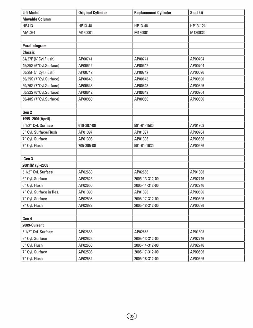
Lift Model Original Cylinder Replacement Cylinder Seal kit
Movable Column
HP413 HP13-48 HP13-48 HP13-124
MACH4 M130001 M130001 M130033
Parallelogram
Classic
34/27F (6”Cyl.Flush) AP00741 AP00741 AP00704
45/35S (6”Cyl.Surface) AP00642 AP00642 AP00704
50/25F (7”Cyl.Flush) AP00742 AP00742 AP00696
50/25S (7”Cyl.Surface) AP00643 AP00643 AP00696
50/26S (7”Cyl.Surface) AP00643 AP00643 AP00696
50/32S (6”Cyl.Surface) AP00642 AP00642 AP00704
50/48S (7”Cyl.Surface) AP00950 AP00950 AP00696
Gen 2
1995- 2001(April)
5 1/2” Cyl. Surface 610-307-00 591-01-1580 AP01808
6” Cyl. Surface/Flush AP01397 AP01397 AP00704
7” Cyl. Surface AP01398 AP01398 AP00696
7” Cyl. Flush 705-305-00 591-01-1630 AP00696
Gen 3
2001(May)-2008
5 1/2” Cyl. Surface AP02668 AP02668 AP01808
6” Cyl. Surface AP02626 2005-13-312-00 AP02746
6” Cyl. Flush AP02650 2005-14-312-00 AP02746
7” Cyl. Surface in Res. AP01398 AP01398 AP00696
7” Cyl. Surface AP02598 2005-17-312-00 AP00696
7” Cyl. Flush AP02682 2005-18-312-00 AP00696
Gen 4
2009-Current
5 1/2” Cyl. Surface AP02668 AP02668 AP01808
6” Cyl. Surface AP02626 2005-13-312-00 AP02746
6” Cyl. Flush AP02650 2005-14-312-00 AP02746
7” Cyl. Surface AP02598 2005-17-312-00 AP00696
7” Cyl. Flush AP02682 2005-18-312-00 AP00696

© Rotary®, Printed in U.S.A., All RightsReserved. Unless otherwise indicated, ROTARY, DOVER and all other trademarks are property of Dover Corporation and its affiliates.
Rotary World Headquarters2700 Lanier DriveMadison, IN 47250, USAwww.rotarylift.com
North America Contact Information Tech. Support: p 800.445.5438 f 800.578.5438 e [email protected] Sales: p 800.640.5438 f 800.578.5438 e [email protected]
World Wide Contact InformationWorld Headquarters/USA: 1.812.273.1622Canada: 1.905.812.9920European Headquarters/Germany: +49.771.9233.0United Kingdom: +44.178.747.7711Australasia: +60.3.7660.0285Latin America / Caribbean: +54.3488.431.608Middle East / Northern Africa: +49.771.9233.0