cx-programmer v9 operation manual fb st.pdf
TRANSCRIPT
8/11/2019 CX-Programmer V9 Operation Manual FB ST.pdf
http://slidepdf.com/reader/full/cx-programmer-v9-operation-manual-fb-stpdf 1/254
OPERATION MANUAL
Function Blocks/Structured Text
Cat. No. W447-E1-13
SYSMAC
CX-Programmer Ver. 9.@CXONE-AL@@C-V4/AL@@D-V4

8/11/2019 CX-Programmer V9 Operation Manual FB ST.pdf
http://slidepdf.com/reader/full/cx-programmer-v9-operation-manual-fb-stpdf 2/254
8/11/2019 CX-Programmer V9 Operation Manual FB ST.pdf
http://slidepdf.com/reader/full/cx-programmer-v9-operation-manual-fb-stpdf 3/254
SYSMAC
CX-Programmer Ver. 9.@
CXONE-AL@@C-V4/AL@@D-V4
Operation Manual
Function Blocks/Structured Text
Revised August 2012

8/11/2019 CX-Programmer V9 Operation Manual FB ST.pdf
http://slidepdf.com/reader/full/cx-programmer-v9-operation-manual-fb-stpdf 4/254
iv
8/11/2019 CX-Programmer V9 Operation Manual FB ST.pdf
http://slidepdf.com/reader/full/cx-programmer-v9-operation-manual-fb-stpdf 5/254
v
Notice: OMRON products are manufactured for use according to proper procedures by a qualified operatorand only for the purposes described in this manual.
The following conventions are used to indicate and classify precautions in this manual. Always heedthe information provided with them. Failure to heed precautions can result in injury to people or dam-age to property.
!DANGER Indicates an imminently hazardous situation which, if not avoided, will result in death or
serious injury. Additionally, there may be severe property damage.
!WARNING Indicates a potentially hazardous situation which, if not avoided, could result in death or
serious injury. Additionally, there may be severe property damage.
!Caution Indicates a potentially hazardous situation which, if not avoided, may result in minor ormoderate injury, or property damage.
OMRON Product References All OMRON products are capitalized in this manual. The word “Unit” is also capitalized when it refers toan OMRON product, regardless of whether or not it appears in the proper name of the product.
The abbreviation “Ch,” which appears in some displays and on some OMRON products, often means“word” and is abbreviated “Wd” in documentation in this sense.
The abbreviation “PLC” means Programmable Controller. “PC” is used, however, in some Program-ming Device displays to mean Programmable Controller.
Visual Aids The following headings appear in the left column of the manual to help you locate different types of
information.Note Indicates information of particular interest for efficient and convenient opera-
tion of the product.
1,2,3... 1. Indicates lists of one sort or another, such as procedures, checklists, etc.
© OMRON, 2008All rights reserved. No part of this publication may be reproduced, stored in a retrieval system, or transmitted, in any form, or
by any means, mechanical, electronic, photocopying, recording, or otherwise, without the prior written permission of
OMRON.
No patent liability is assumed with respect to the use of the information contained herein. Moreover, because OMRON is con-
stantly striving to improve its high-quality products, the information contained in this manual is subject to change without
notice. Every precaution has been taken in the preparation of this manual. Nevertheless, OMRON assumes no responsibility
for errors or omissions. Neither is any liability assumed for damages resulting from the use of the information contained in
this publication.

8/11/2019 CX-Programmer V9 Operation Manual FB ST.pdf
http://slidepdf.com/reader/full/cx-programmer-v9-operation-manual-fb-stpdf 6/254
vi
8/11/2019 CX-Programmer V9 Operation Manual FB ST.pdf
http://slidepdf.com/reader/full/cx-programmer-v9-operation-manual-fb-stpdf 7/254
Part 1: Function Block
Part 2: Structured Text
SECTION 1 Introduction to Function Blocks
SECTION 2 Function Block Specifications
SECTION 3 Creating Function Blocks
SECTION 4 Introduction to Structured Text
SECTION 5 Structured Text (ST) Language Specifica-tions
SECTION 6 Creating ST Programs
Appendices

8/11/2019 CX-Programmer V9 Operation Manual FB ST.pdf
http://slidepdf.com/reader/full/cx-programmer-v9-operation-manual-fb-stpdf 8/254
8/11/2019 CX-Programmer V9 Operation Manual FB ST.pdf
http://slidepdf.com/reader/full/cx-programmer-v9-operation-manual-fb-stpdf 9/254
ix
TABLE OF CONTENTS
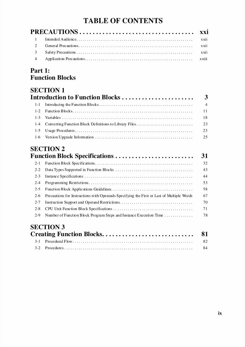
PRECAUTIONS . . . . . . . . . . . . . . . . . . . . . . . . . . . . . . . . . . . xxi1 Intended Audience. . . . . . . . . . . . . . . . . . . . . . . . . . . . . . . . . . . . . . . . . . . . . . . . . . . . . . . . . xxii
2 General Precautions. . . . . . . . . . . . . . . . . . . . . . . . . . . . . . . . . . . . . . . . . . . . . . . . . . . . . . . . xxii
3 Safety Precautions . . . . . . . . . . . . . . . . . . . . . . . . . . . . . . . . . . . . . . . . . . . . . . . . . . . . . . . . . xxii
4 Application Precautions. . . . . . . . . . . . . . . . . . . . . . . . . . . . . . . . . . . . . . . . . . . . . . . . . . . . . xxiii
Part 1:Function Blocks
SECTION 1Introduction to Function Blocks . . . . . . . . . . . . . . . . . . . . . . 3
1-1 Introducing the Function Blocks . . . . . . . . . . . . . . . . . . . . . . . . . . . . . . . . . . . . . . . . . . . . . . 4
1-2 Function Blocks. . . . . . . . . . . . . . . . . . . . . . . . . . . . . . . . . . . . . . . . . . . . . . . . . . . . . . . . . . . 11
1-3 Variables . . . . . . . . . . . . . . . . . . . . . . . . . . . . . . . . . . . . . . . . . . . . . . . . . . . . . . . . . . . . . . . . 18
1-4 Converting Function Block Definitions to Library Files. . . . . . . . . . . . . . . . . . . . . . . . . . . . 23
1-5 Usage Procedures. . . . . . . . . . . . . . . . . . . . . . . . . . . . . . . . . . . . . . . . . . . . . . . . . . . . . . . . . . 23
1-6 Version Upgrade Information . . . . . . . . . . . . . . . . . . . . . . . . . . . . . . . . . . . . . . . . . . . . . . . . 25
SECTION 2Function Block Specifications . . . . . . . . . . . . . . . . . . . . . . . . 31
2-1 Function Block Specifications. . . . . . . . . . . . . . . . . . . . . . . . . . . . . . . . . . . . . . . . . . . . . . . . 32
2-2 Data Types Supported in Function Blocks . . . . . . . . . . . . . . . . . . . . . . . . . . . . . . . . . . . . . . 43
2-3 Instance Specifications . . . . . . . . . . . . . . . . . . . . . . . . . . . . . . . . . . . . . . . . . . . . . . . . . . . . . 44
2-4 Programming Restrictions . . . . . . . . . . . . . . . . . . . . . . . . . . . . . . . . . . . . . . . . . . . . . . . . . . . 53
2-5 Function Block Applications Guidelines. . . . . . . . . . . . . . . . . . . . . . . . . . . . . . . . . . . . . . . . 58
2-6 Precautions for Instructions with Operands Specifying the First or Last of Multiple Words 67
2-7 Instruction Support and Operand Restrictions. . . . . . . . . . . . . . . . . . . . . . . . . . . . . . . . . . . . 70
2-8 CPU Unit Function Block Specifications . . . . . . . . . . . . . . . . . . . . . . . . . . . . . . . . . . . . . . . 71
2-9 Number of Function Block Program Steps and Instance Execution Time . . . . . . . . . . . . . . 78
SECTION 3Creating Function Blocks. . . . . . . . . . . . . . . . . . . . . . . . . . . . 81
3-1 Procedural Flow. . . . . . . . . . . . . . . . . . . . . . . . . . . . . . . . . . . . . . . . . . . . . . . . . . . . . . . . . . . 823-2 Procedures . . . . . . . . . . . . . . . . . . . . . . . . . . . . . . . . . . . . . . . . . . . . . . . . . . . . . . . . . . . . . . . 84
8/11/2019 CX-Programmer V9 Operation Manual FB ST.pdf
http://slidepdf.com/reader/full/cx-programmer-v9-operation-manual-fb-stpdf 10/254
x
TABLE OF CONTENTS
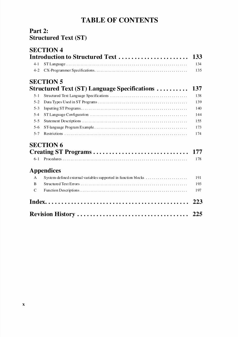
Part 2:Structured Text (ST)
SECTION 4
Introduction to Structured Text . . . . . . . . . . . . . . . . . . . . . . 1334-1 ST Language . . . . . . . . . . . . . . . . . . . . . . . . . . . . . . . . . . . . . . . . . . . . . . . . . . . . . . . . . . . . . 134
4-2 CX-Programmer Specifications. . . . . . . . . . . . . . . . . . . . . . . . . . . . . . . . . . . . . . . . . . . . . . . 135
SECTION 5Structured Text (ST) Language Specifications . . . . . . . . . . 137
5-1 Structured Text Language Specifications . . . . . . . . . . . . . . . . . . . . . . . . . . . . . . . . . . . . . . . 138
5-2 Data Types Used in ST Programs . . . . . . . . . . . . . . . . . . . . . . . . . . . . . . . . . . . . . . . . . . . . . 139
5-3 Inputting ST Programs. . . . . . . . . . . . . . . . . . . . . . . . . . . . . . . . . . . . . . . . . . . . . . . . . . . . . . 140
5-4 ST Language Configuration . . . . . . . . . . . . . . . . . . . . . . . . . . . . . . . . . . . . . . . . . . . . . . . . . 144
5-5 Statement Descriptions . . . . . . . . . . . . . . . . . . . . . . . . . . . . . . . . . . . . . . . . . . . . . . . . . . . . . 155
5-6 ST-language Program Example . . . . . . . . . . . . . . . . . . . . . . . . . . . . . . . . . . . . . . . . . . . . . . . 173
5-7 Restrictions . . . . . . . . . . . . . . . . . . . . . . . . . . . . . . . . . . . . . . . . . . . . . . . . . . . . . . . . . . . . . . 174
SECTION 6Creating ST Programs . . . . . . . . . . . . . . . . . . . . . . . . . . . . . . 177
6-1 Procedures . . . . . . . . . . . . . . . . . . . . . . . . . . . . . . . . . . . . . . . . . . . . . . . . . . . . . . . . . . . . . . . 178
Appendices
A System-defined external variables supported in function blocks . . . . . . . . . . . . . . . . . . . . . 191
B Structured Text Errors . . . . . . . . . . . . . . . . . . . . . . . . . . . . . . . . . . . . . . . . . . . . . . . . . . . . . . 193
C Function Descriptions . . . . . . . . . . . . . . . . . . . . . . . . . . . . . . . . . . . . . . . . . . . . . . . . . . . . . . 197
Index. . . . . . . . . . . . . . . . . . . . . . . . . . . . . . . . . . . . . . . . . . . . . 223
Revision History . . . . . . . . . . . . . . . . . . . . . . . . . . . . . . . . . . . 225
8/11/2019 CX-Programmer V9 Operation Manual FB ST.pdf
http://slidepdf.com/reader/full/cx-programmer-v9-operation-manual-fb-stpdf 11/254
xi
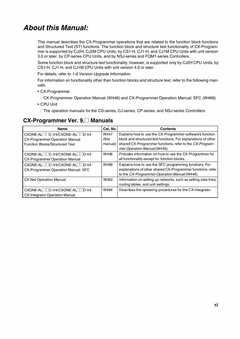
About this Manual:
This manual describes the CX-Programmer operations that are related to the function block functionsand Structured Text (ST) functions. The function block and structure text functionality of CX-Program-mer is supported by CJ2H, CJ2M CPU Units, by CS1-H, CJ1-H, and CJ1M CPU Units with unit version3.0 or later, by CP-series CPU Units, and by NSJ-series and FQM1-series Controllers.
Some function block and structure text functionality, however, is supported only by CJ2H CPU Units, byCS1-H, CJ1-H, and CJ1M CPU Units with unit version 4.0 or later.
For details, refer to 1-6 Version Upgrade Information .
For information on functionality other than function blocks and structure text, refer to the following man-uals.
• CX-Programmer
: CX-Programmer Operation Manual (W446) and CX-Programmer Operation Manual: SFC (W469)
• CPU Unit
: The operation manuals for the CS-series, CJ-series, CP-series, and NSJ-series Controllers
CX-Programmer Ver. 9.@ Manuals
Name Cat. No. Contents
CXONE-AL@@C-V4/CXONE-AL@@D-V4
CX-Programmer Operation Manual
Function Blocks/Structured Text
W447
(this
manual)
Explains how to use the CX-Programmer software’s function
block and structured text functions. For explanations of other
shared CX-Programmer functions, refer to the CX-Program-
mer Operation Manual (W446).
CXONE-AL@@C-V4/CXONE-AL@@D-V4
CX-Programmer Operation Manual
W446 Provides information on how to use the CX-Programmer for
all functionality except for function blocks.
CXONE-AL@@C-V4/CXONE-AL@@D-V4
CX-Programmer Operation Manual: SFC
W469 Explains how to use the SFC programming functions. For
explanations of other shared CX-Programmer functions, refer
to the CX-Programmer Operation Manual (W446).
CX-Net Operation Manual W362 Information on setting up networks, such as setting data links,
routing tables, and unit settings.
CXONE-AL@@C-V4/CXONE-AL@@D-V4
CX-Integrator Operation Manual
W464 Describes the operating procedures for the CX-Integrator.
8/11/2019 CX-Programmer V9 Operation Manual FB ST.pdf
http://slidepdf.com/reader/full/cx-programmer-v9-operation-manual-fb-stpdf 12/254
8/11/2019 CX-Programmer V9 Operation Manual FB ST.pdf
http://slidepdf.com/reader/full/cx-programmer-v9-operation-manual-fb-stpdf 13/254
xiii
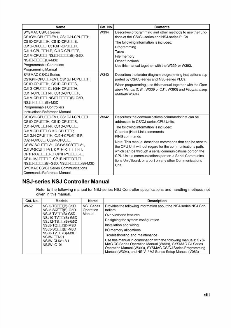
NSJ-series NSJ Controller Manual
Refer to the following manual for NSJ-series NSJ Controller specifications and handling methods notgiven in this manual.
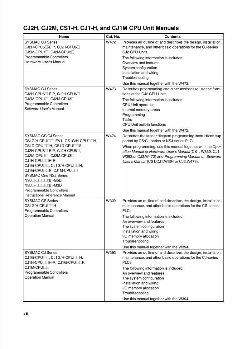
SYSMAC CS/CJ Series
CS1G/H-CPU@@-EV1, CS1G/H-CPU@@H,
CS1D-CPU@@H, CS1D-CPU@@S,
CJ1G-CPU@@, CJ1G/H-CPU@@H,
CJ1H-CPU@@H-R, CJ1G-CPU@@P,
CJ1M-CPU@@, NSJ@-@@@@(B)-G5D,NSJ@-@@@@(B)-M3D
Programmable Controllers
Programming Manual
W394 Describes programming and other methods to use the func-
tions of the CS/CJ-series and NSJ-series PLCs.
The following information is included:
Programming
Tasks
File memoryOther functions
Use this manual together with the W339 or W393.
SYSMAC CS/CJ Series
CS1G/H-CPU@@-EV1, CS1G/H-CPU@@H,
CS1D-CPU@@H, CS1D-CPU@@S,
CJ1G-CPU@@, CJ1G/H-CPU@@H,
CJ1H-CPU@@H-R, CJ1G-CPU@@P,
CJ1M-CPU@@, NSJ@-@@@@(B)-G5D,
NSJ@-@@@@(B)-M3D
Programmable Controllers
Instructions Reference Manual
W340 Describes the ladder diagram programming instructions sup-
ported by CS/CJ-series and NSJ-series PLCs.
When programming, use this manual together with the Oper-
ation Manual (CS1: W339 or CJ1: W393) and Programming
Manual (W394).
CS1G/H-CPU@@-EV1, CS1G/H-CPU@@H
CS1D-CPU@@H, CS1D-CPU@@S,
CJ1H-CPU@@H-R, CJ1G-CPU@@,
CJ1M-CPU@@, CJ1G-CPU@@P,
CJ1G/H-CPU@@H, CJ2H-CPU6@-EIP,
CJ2H-CPU6@, CJ2M-CPU@@,
CS1W-SCU@@-V1, CS1W-SCB@@-V1,
CJ1W-SCU@@-V1, CP1H-X@@@@-@,
CP1H-XA@@@@-@, CP1H-Y@@@@-@,
CP1L-M/L@@@-@, CP1E-N@@D@-@NSJ@-@@@@(B)-G5D, NSJ@-@@@@(B)-M3D
SYSMAC CS/CJ Series Communications
Commands Reference Manual
W342 Describes the communications commands that can be
addressed to CS/CJ-series CPU Units.
The following information is included:
C-series (Host Link) commands
FINS commands
Note: This manual describes commands that can be sent to
the CPU Unit without regard for the communications path,
which can be through a serial communications port on the
CPU Unit, a communications port on a Serial Communica-
tions Unit/Board, or a port on any other Communications
Unit.
Cat. No. Models Name Description
W452 NSJ5-TQ@@(B)-G5DNSJ5-SQ@@(B)-G5DNSJ8-TV@@(B)-G5DNSJ10-TV@@(B)-G5DNSJ12-TS@@(B)-G5DNSJ5-TQ@@(B)-M3D
NSJ5-SQ@@(B)-M3DNSJ8-TV@@(B)-M3DNSJW-ETN21NSJW-CLK21-V1NSJW-IC101
NSJ SeriesOperationManual
Provides the following information about the NSJ-series NSJ Con-trollers:
Overview and features
Designing the system configuration
Installation and wiring
I/O memory allocationsTroubleshooting and maintenance
Use this manual in combination with the following manuals: SYS-MAC CS Series Operation Manual (W339), SYSMAC CJ SeriesOperation Manual (W393), SYSMAC CS/CJ Series ProgrammingManual (W394), and NS-V1/-V2 Series Setup Manual (V083)
Name Cat. No. Contents
8/11/2019 CX-Programmer V9 Operation Manual FB ST.pdf
http://slidepdf.com/reader/full/cx-programmer-v9-operation-manual-fb-stpdf 14/254
xiv
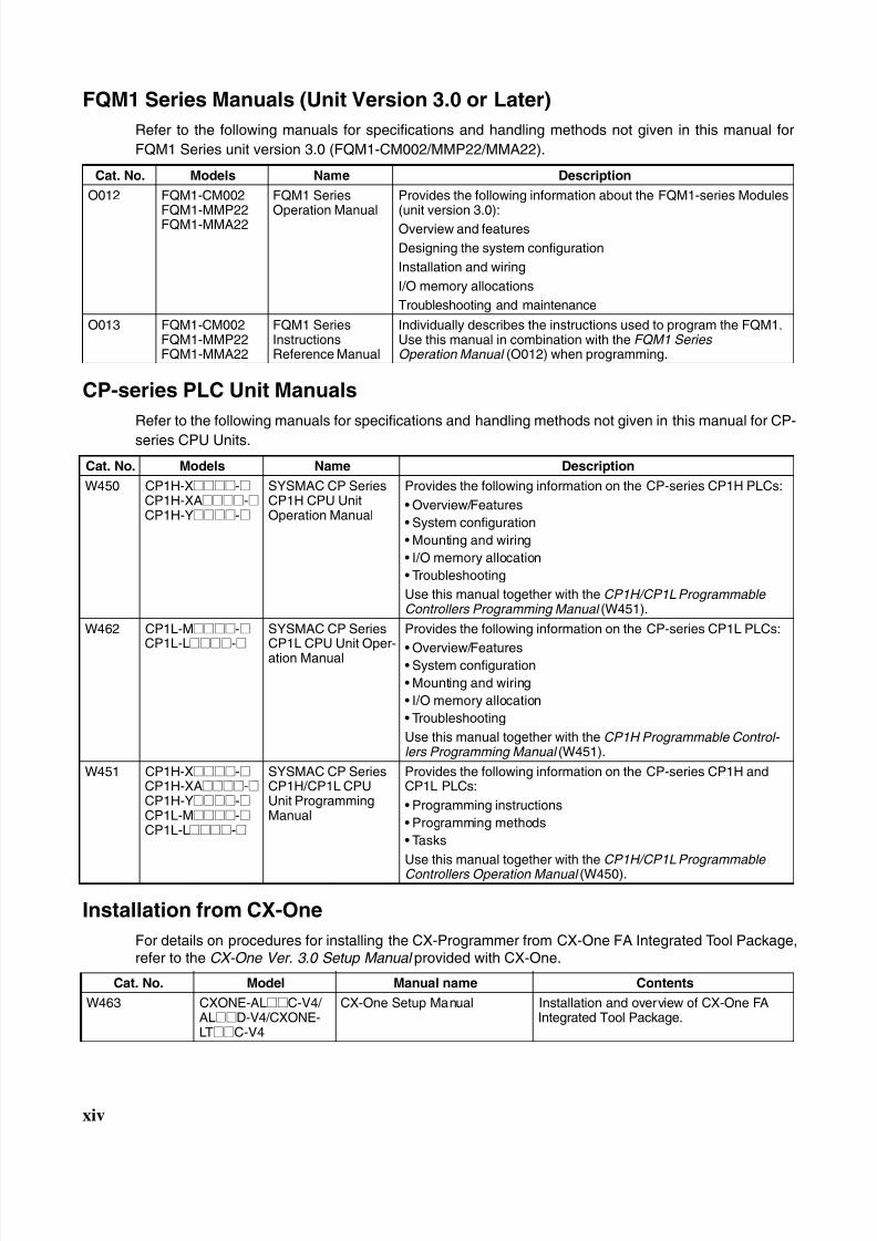
FQM1 Series Manuals (Unit Version 3.0 or Later)
Refer to the following manuals for specifications and handling methods not given in this manual for
FQM1 Series unit version 3.0 (FQM1-CM002/MMP22/MMA22).
CP-series PLC Unit Manuals
Refer to the following manuals for specifications and handling methods not given in this manual for CP-
series CPU Units.
Installation from CX-One
For details on procedures for installing the CX-Programmer from CX-One FA Integrated Tool Package,refer to the CX-One Ver. 3.0 Setup Manual provided with CX-One.
Cat. No. Models Name Description
O012 FQM1-CM002
FQM1-MMP22FQM1-MMA22
FQM1 Series
Operation Manual
Provides the following information about the FQM1-series Modules
(unit version 3.0):Overview and features
Designing the system configuration
Installation and wiring
I/O memory allocations
Troubleshooting and maintenance
O013 FQM1-CM002FQM1-MMP22FQM1-MMA22
FQM1 SeriesInstructionsReference Manual
Individually describes the instructions used to program the FQM1.Use this manual in combination with the FQM1 Series Operation Manual (O012) when programming.
Cat. No. Models Name Description
W450 CP1H-X@@@@-@CP1H-XA@@@@-@CP1H-Y@@@@-@
SYSMAC CP SeriesCP1H CPU UnitOperation Manual
Provides the following information on the CP-series CP1H PLCs:
• Overview/Features
• System configuration
• Mounting and wiring
• I/O memory allocation
• Troubleshooting
Use this manual together with the CP1H/CP1L ProgrammableControllers Programming Manual (W451).
W462 CP1L-M@@@@-@CP1L-L@@@@-@
SYSMAC CP SeriesCP1L CPU Unit Oper-ation Manual
Provides the following information on the CP-series CP1L PLCs:
• Overview/Features• System configuration
• Mounting and wiring
• I/O memory allocation
• Troubleshooting
Use this manual together with the CP1H Programmable Control- lers Programming Manual (W451).
W451 CP1H-X@@@@-@CP1H-XA@@@@-@CP1H-Y@@@@-@CP1L-M@@@@-@CP1L-L@@@@-@
SYSMAC CP SeriesCP1H/CP1L CPUUnit ProgrammingManual
Provides the following information on the CP-series CP1H andCP1L PLCs:
• Programming instructions
• Programming methods
• Tasks
Use this manual together with the CP1H/CP1L ProgrammableControllers Operation Manual (W450).
Cat. No. Model Manual name Contents
W463 CXONE-AL@@C-V4/ AL@@D-V4/CXONE-LT@@C-V4
CX-One Setup Manual Installation and overview of CX-One FAIntegrated Tool Package.
8/11/2019 CX-Programmer V9 Operation Manual FB ST.pdf
http://slidepdf.com/reader/full/cx-programmer-v9-operation-manual-fb-stpdf 15/254
xv
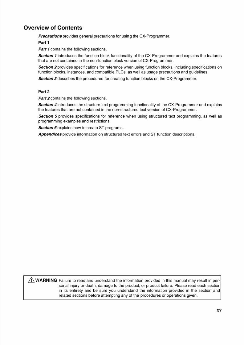
Overview of Contents
Precautions provides general precautions for using the CX-Programmer.
Part 1
Part 1 contains the following sections.
Section 1 introduces the function block functionality of the CX-Programmer and explains the features
that are not contained in the non-function block version of CX-Programmer.Section 2 provides specifications for reference when using function blocks, including specifications onfunction blocks, instances, and compatible PLCs, as well as usage precautions and guidelines.
Section 3 describes the procedures for creating function blocks on the CX-Programmer.
Part 2
Part 2 contains the following sections.
Section 4 introduces the structure text programming functionality of the CX-Programmer and explainsthe features that are not contained in the non-structured text version of CX-Programmer.
Section 5 provides specifications for reference when using structured text programming, as well as
programming examples and restrictions.Section 6 explains how to create ST programs.
Appendices provide information on structured text errors and ST function descriptions.
!WARNING Failure to read and understand the information provided in this manual may result in per-sonal injury or death, damage to the product, or product failure. Please read each sectionin its entirety and be sure you understand the information provided in the section andrelated sections before attempting any of the procedures or operations given.

8/11/2019 CX-Programmer V9 Operation Manual FB ST.pdf
http://slidepdf.com/reader/full/cx-programmer-v9-operation-manual-fb-stpdf 16/254
xvi
8/11/2019 CX-Programmer V9 Operation Manual FB ST.pdf
http://slidepdf.com/reader/full/cx-programmer-v9-operation-manual-fb-stpdf 17/254
xvii
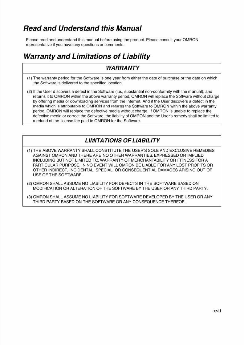
Read and Understand this Manual
Please read and understand this manual before using the product. Please consult your OMRONrepresentative if you have any questions or comments.
Warranty and Limitations of Liability
WARRANTY
(1) The warranty period for the Software is one year from either the date of purchase or the date on whichthe Software is delivered to the specified location.
(2) If the User discovers a defect in the Software (i.e., substantial non-conformity with the manual), andreturns it to OMRON within the above warranty period, OMRON will replace the Software without chargeby offering media or downloading services from the Internet. And if the User discovers a defect in themedia which is attributable to OMRON and returns the Software to OMRON within the above warrantyperiod, OMRON will replace the defective media without charge. If OMRON is unable to replace thedefective media or correct the Software, the liability of OMRON and the User's remedy shall be limited to
a refund of the license fee paid to OMRON for the Software.
LIMITATIONS OF LIABILITY
(1) THE ABOVE WARRANTY SHALL CONSTITUTE THE USER'S SOLE AND EXCLUSIVE REMEDIESAGAINST OMRON AND THERE ARE NO OTHER WARRANTIES, EXPRESSED OR IMPLIED,INCLUDING BUT NOT LIMITED TO, WARRANTY OF MERCHANTABILITY OR FITNESS FOR APARTICULAR PURPOSE. IN NO EVENT WILL OMRON BE LIABLE FOR ANY LOST PROFITS OROTHER INDIRECT, INCIDENTAL, SPECIAL, OR CONSEQUENTIAL DAMAGES ARISING OUT OFUSE OF THE SOFTWARE.
(2) OMRON SHALL ASSUME NO LIABILITY FOR DEFECTS IN THE SOFTWARE BASED ONMODIFICATION OR ALTERATION OF THE SOFTWARE BY THE USER OR ANY THIRD PARTY.
(3) OMRON SHALL ASSUME NO LIABILITY FOR SOFTWARE DEVELOPED BY THE USER OR ANYTHIRD PARTY BASED ON THE SOFTWARE OR ANY CONSEQUENCE THEREOF.

8/11/2019 CX-Programmer V9 Operation Manual FB ST.pdf
http://slidepdf.com/reader/full/cx-programmer-v9-operation-manual-fb-stpdf 18/254
xviii
Application Considerations
SUITABILITY FOR USE
THE USER SHALL NOT USE THE SOFTWARE FOR A PURPOSE THAT IS NOT DESCRIBED IN THEATTACHED USER MANUAL.
8/11/2019 CX-Programmer V9 Operation Manual FB ST.pdf
http://slidepdf.com/reader/full/cx-programmer-v9-operation-manual-fb-stpdf 19/254
xix
Disclaimers
CHANGE IN SPECIFICATIONS
The software specifications and accessories may be changed at any time based on improvements or forother reasons.
EXTENT OF SERVICE
The license fee of the Software does not include service costs, such as dispatching technical staff.
ERRORS AND OMISSIONS
The information in this manual has been carefully checked and is believed to be accurate; however, no
responsibility is assumed for clerical, typographical, or proofreading errors, or omissions.

8/11/2019 CX-Programmer V9 Operation Manual FB ST.pdf
http://slidepdf.com/reader/full/cx-programmer-v9-operation-manual-fb-stpdf 20/254
xx
8/11/2019 CX-Programmer V9 Operation Manual FB ST.pdf
http://slidepdf.com/reader/full/cx-programmer-v9-operation-manual-fb-stpdf 21/254
xxi
PRECAUTIONS
This section provides general precautions for using the CX-Programmer and the Programmable Logic Controller.
The information contained in this section is important for the safe and reliable application of the CX-Programmer
and Programmable Controller. You must read this section and understand the information contained before
attempting to set up or operate the CX-Programmer and Programmable Controller.
1 Intended Audience . . . . . . . . . . . . . . . . . . . . . . . . . . . . . . . . . . . . . . . . . . . . . xxii
2 General Precautions . . . . . . . . . . . . . . . . . . . . . . . . . . . . . . . . . . . . . . . . . . . . xxii
3 Safety Precautions. . . . . . . . . . . . . . . . . . . . . . . . . . . . . . . . . . . . . . . . . . . . . . xxii
4 Application Precautions . . . . . . . . . . . . . . . . . . . . . . . . . . . . . . . . . . . . . . . . . xxiii
8/11/2019 CX-Programmer V9 Operation Manual FB ST.pdf
http://slidepdf.com/reader/full/cx-programmer-v9-operation-manual-fb-stpdf 22/254
xxii
Intended Audience 1
1 Intended Audience
This manual is intended for the following personnel, who must also haveknowledge of electrical systems (an electrical engineer or the equivalent).
• Personnel in charge of installing FA systems.
• Personnel in charge of designing FA systems.
• Personnel in charge of managing FA systems and facilities.
2 General Precautions
The user must operate the product according to the performance specifica-tions described in the operation manuals.
Before using the product under conditions which are not described in themanual or applying the product to nuclear control systems, railroad systems,aviation systems, vehicles, combustion systems, medical equipment, amuse-ment machines, safety equipment, and other systems, machines, and equip-ment that may have a serious influence on lives and property if usedimproperly, consult your OMRON representative.
Make sure that the ratings and performance characteristics of the product aresufficient for the systems, machines, and equipment, and be sure to providethe systems, machines, and equipment with double safety mechanisms.
This manual provides information for programming and operating the product.Be sure to read this manual before attempting to use the product and keepthis manual close at hand for reference during operation.
!WARNING It is extremely important that a PLC and all PLC Units be used for the speci-fied purpose and under the specified conditions, especially in applications thatcan directly or indirectly affect human life. You must consult with your OMRONrepresentative before applying a PLC System to the above-mentioned appli-cations.
3 Safety Precautions
!WARNING Confirm safety sufficiently before transferring I/O memory area status from theCX-Programmer to the actual CPU Unit. The devices connected to OutputUnits may malfunction, regardless of the operating mode of the CPU Unit.Caution is required in respect to the following functions.
• Transferring from the CX-Programmer to real I/O (CIO Area) in the CPUUnit using the PLC Memory Window.
• Transferring from file memory to real I/O (CIO Area) in the CPU Unit usingthe Memory Card Window.
!Caution Variables must be specified either with AT settings (or external variables), orthe variables must be the same size as the data size to be processed by theinstruction when specifying the first or last address of multiple words in theinstruction operand.
1. If a non-array variable with a different data size and without an AT settingis specified, the CX-Programmer will output an error when compiling.
2. Array Variable Specifications
8/11/2019 CX-Programmer V9 Operation Manual FB ST.pdf
http://slidepdf.com/reader/full/cx-programmer-v9-operation-manual-fb-stpdf 23/254
xxiii
Application Precautions 4
• When the size to be processed by the instruction operand is fixed:The number of array elements must be the same as the number of ele-ments to be processed by the instruction. Otherwise, the CX-Programmerwill output an error when compiling.
• When the size to be processed by the instruction operand is not fixed:The number of array elements must be greater than or the same as thesize specified in the other operands.
• If the other operand specifying a size is a constant, the CX-Program-mer will output an error when compiling.
• If the other operand specifying a size is a variable, the CX-Programmerwill not output an error when compiling, even if the size of the arrayvariable is not the same as that specified by the other operand (vari-able). A warning message, however, will be displayed. In particular, ifthe number of array elements is less than the size specified by the oth-er operand (e.g., the size of the instruction operand is 16, and the num-ber of elements registered in the actual variable table is 10), theinstruction will execute read/write processing for the area that exceedsthe number of elements. For example, read/write processing will be ex-
ecuted for the 6 words following those for the number of elements reg-istered in the actual variable table. If these words are used for otherinstructions (including internal variable allocations), unexpected oper-ation will occur, which may result in serious accidents.Check that the system will not be adversely affected if the size of thevariable specified in the operand is less than the size in the operanddefinition before starting PLC operations.
!Caution Confirm safety at the destination node before transferring a program toanother node or changing contents of the I/O memory area. Doing either ofthese without confirming safety may result in injury.
!Caution Execute online editing only after confirming that no adverse effects will becaused by extending the cycle time. Otherwise, the input signals may not bereadable.
!Caution If synchronous unit operation is being used, perform online editing only afterconfirming that an increased synchronous processing time will not affect theoperation of the main and slave axes.
!Caution Confirm safety sufficiently before monitoring power flow and present valuestatus in the Ladder Section Window or when monitoring present values in theWatch Window. If force-set/reset or set/reset operations are inadvertently per-formed by pressing short-cut keys, the devices connected to Output Units
may malfunction, regardless of the operating mode of the CPU Unit.
4 Application Precautions
Observe the following precautions when using the CX-Programmer.
• User programs cannot be uploaded to the CX-Programmer.
• Observe the following precautions before starting the CX-Programmer.
• Exit all applications not directly related to the CX-Programmer. Partic-ularly exit any software such as screen savers, virus checkers, E-mailor other communications software, and schedulers or other applica-tions that start up periodically or automatically.
8/11/2019 CX-Programmer V9 Operation Manual FB ST.pdf
http://slidepdf.com/reader/full/cx-programmer-v9-operation-manual-fb-stpdf 24/254
xxiv
Application Precautions 4
• Disable sharing hard disks, printers, or other devices with other com-puters on any network.
• With some notebook computers, the RS-232C port is allocated to amodem or an infrared line by default. Following the instructions in doc-umentation for your computer and enable using the RS-232C port asa normal serial port.
• With some notebook computers, the default settings for saving energydo not supply the rated power to the RS-232C, USB and Ethernet port.There may be both Windows settings for saving energy, as well as set-ting for specific computer utilities and the BIOS. Following the instruc-tions in documentation for your computer, disable all energy savingsettings.
• Do not turn OFF the power supply to the PLC or disconnect the connect-ing cable while the CX-Programmer is online with the PLC. The computermay malfunction.
• Confirm that no adverse effects will occur in the system before attemptingany of the following. Not doing so may result in an unexpected operation.
• Changing the operating mode of the PLC.
• Force-setting/force-resetting any bit in memory.
• Changing the present value of any word or any set value in memory.
• Check the user program for proper execution before actually running it onthe Unit. Not checking the program may result in an unexpected opera-tion.
• When online editing is performed, the user program and parameter areadata in CJ2, CS1-H, CJ1-H, CJ1M, and CP1H CPU Units is backed up inthe built-in flash memory. The BKUP indicator will light on the front of theCPU Unit when the backup operation is in progress. Do not turn OFF thepower supply to the CPU Unit when the BKUP indicator is lit. The data willnot be backed up if power is turned OFF. To display the status of writing to
flash memory on the CX-Programmer, select Display dialog to show PLC Memory Backup Status in the PLC properties and then select Windows - PLC Memory Backup Status from the View Menu.
• Programs including function blocks (ladder programming language orstructured text (ST) language) can be downloaded or uploaded in thesame way as standard programs that do not contain function blocks.Tasks including function blocks, however, cannot be downloaded in taskunits (uploading is possible).
• If a user program containing function blocks created on the CX-Program-mer Ver. 5.0 or later is downloaded to a CPU Unit that does not supportfunction blocks (CS/CJ-series CPU Units with unit version 2.0 or earlier),all instances will be treated as illegal commands and it will not be possible
to edit or execute the user program.• If the input variable data is not in boolean format, and numerical values
only (e.g., 20) are input in the parameters, the actual value in the CIOArea address (e.g., 0020) will be passed. Therefore, be sure to include an&, #, or +, - prefix before inputting the numerical value.
• Addresses can be set in input parameters, but an address itself cannot bepassed as an input variable. (Even if an address is set as an input param-eter, the value passed to the function block will be that for the size of dataof the input variable.) Therefore, an input variable cannot be used as theoperand of an instruction in the function block when the operand specifiesthe first or last of multiple words. With CX-Programmer version 7.0, use
8/11/2019 CX-Programmer V9 Operation Manual FB ST.pdf
http://slidepdf.com/reader/full/cx-programmer-v9-operation-manual-fb-stpdf 25/254
xxv
Application Precautions 4
an input-output variable specified as an array variable (with the firstaddress set for the input parameter) and specify the first or last element ofthe array variable, or, with any version of CX-Programmer, use an internalvariable with an AT setting. Alternatively, specify the first or last element inan internal variable specified as an array variable.
• Values are passed in a batch from the input parameters to the input vari-ables or input-output variables before algorithm execution (not at thesame time as the instructions in the algorithm are executed). Therefore, topass the value from a parameter to an input variable or input-output vari-able when an instruction in the function block algorithm is executed, usean internal variable or external variable instead of an input variable orinput-output variable. The same applies to the timing for writing values tothe parameters from output variables.
• Always use internal variables with AT settings in the following cases.
• The addresses allocated to Basic I/O Units, Special I/O Units, andCPU Bus Units cannot be registered to global symbols, and these vari-ables cannot be specified as external variables (e.g., the data set forglobal variables may not be stable).
• Use internal variables when Auxiliary Area bits other than those pre-registered to external variables are registered to global symbols andthese variables are not specified as external variables.
• Use internal variables when specifying PLC addresses for anothernode on the network: For example, the first destination word at the re-mote node for SEND(090) and the first source word at the remote nodefor RECV(098).
• Use internal variables when the first or last of multiple words is speci-fied by an instruction operand and the operand cannot be specified asan array variable (e.g., the number of array elements cannot be spec-ified).
8/11/2019 CX-Programmer V9 Operation Manual FB ST.pdf
http://slidepdf.com/reader/full/cx-programmer-v9-operation-manual-fb-stpdf 26/254
xxvi
Application Precautions 4
8/11/2019 CX-Programmer V9 Operation Manual FB ST.pdf
http://slidepdf.com/reader/full/cx-programmer-v9-operation-manual-fb-stpdf 27/254
Part 1:
Function Blocks

8/11/2019 CX-Programmer V9 Operation Manual FB ST.pdf
http://slidepdf.com/reader/full/cx-programmer-v9-operation-manual-fb-stpdf 28/254
8/11/2019 CX-Programmer V9 Operation Manual FB ST.pdf
http://slidepdf.com/reader/full/cx-programmer-v9-operation-manual-fb-stpdf 29/254
3
SECTION 1Introduction to Function Blocks
This section introduces the function block functionality of the CX-Programmer and explains the features that are not
contained in the non-function block version of CX-Programmer.
1-1 Introducing the Function Blocks. . . . . . . . . . . . . . . . . . . . . . . . . . . . . . . . . . . 4
1-1-1 Overview and Features . . . . . . . . . . . . . . . . . . . . . . . . . . . . . . . . . . . 4
1-1-2 Function Block Specifications . . . . . . . . . . . . . . . . . . . . . . . . . . . . . 5
1-1-3 Files Created with CX-Programmer Ver. 6.0 or Later . . . . . . . . . . . 8
1-1-4 Function Block Menus in CX-Programmer Ver. 5.0(and later Versions) . . . . . . . . . . . . . . . . . . . . . . . . . . . . . . . . . . . . . . 8
1-2 Function Blocks . . . . . . . . . . . . . . . . . . . . . . . . . . . . . . . . . . . . . . . . . . . . . . . 11
1-2-1 Outline . . . . . . . . . . . . . . . . . . . . . . . . . . . . . . . . . . . . . . . . . . . . . . . 11
1-2-2 Advantages of Function Blocks . . . . . . . . . . . . . . . . . . . . . . . . . . . . 12
1-2-3 Function Block Structure . . . . . . . . . . . . . . . . . . . . . . . . . . . . . . . . . 13
1-3 Variables . . . . . . . . . . . . . . . . . . . . . . . . . . . . . . . . . . . . . . . . . . . . . . . . . . . . . 18
1-3-1 Introduction. . . . . . . . . . . . . . . . . . . . . . . . . . . . . . . . . . . . . . . . . . . . 18
1-3-2 Variable Usage and Properties . . . . . . . . . . . . . . . . . . . . . . . . . . . . . 19
1-3-3 Variable Properties . . . . . . . . . . . . . . . . . . . . . . . . . . . . . . . . . . . . . . 19
1-3-4 Variable Properties and Variable Usage . . . . . . . . . . . . . . . . . . . . . . 20
1-3-5 Internal Allocation of Variable Addresses . . . . . . . . . . . . . . . . . . . . 21
1-4 Converting Function Block Definitions to Library Files . . . . . . . . . . . . . . . . 23
1-5 Usage Procedures . . . . . . . . . . . . . . . . . . . . . . . . . . . . . . . . . . . . . . . . . . . . . . 23
1-5-1 Creating Function Blocks and Executing Instances . . . . . . . . . . . . . 23
1-5-2 Reusing Function Blocks . . . . . . . . . . . . . . . . . . . . . . . . . . . . . . . . . 24
1-6 Version Upgrade Information . . . . . . . . . . . . . . . . . . . . . . . . . . . . . . . . . . . . . 25
8/11/2019 CX-Programmer V9 Operation Manual FB ST.pdf
http://slidepdf.com/reader/full/cx-programmer-v9-operation-manual-fb-stpdf 30/254
4
Introducing the Function Blocks Section 1-1
1-1 Introducing the Function Blocks
1-1-1 Overview and Features
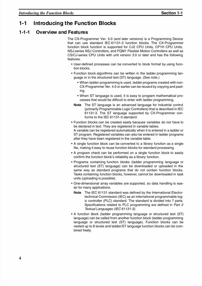
The CX-Programmer Ver. 5.0 (and later versions) is a Programming Devicethat can use standard IEC 61131-3 function blocks. The CX-Programmerfunction block function is supported for CJ2 CPU Units, CP1H CPU Units,
NSJ-series NSJ Controllers, and FQM1 Flexible Motion Controllers as well asCS/CJ-series CPU Units with unit version 3.0 or later and has the followingfeatures.
• User-defined processes can be converted to block format by using func-tion blocks.
• Function block algorithms can be written in the ladder programming lan-guage or in the structured text (ST) language. (See note.)
• When ladder programming is used, ladder programs created with non-CX-Programmer Ver. 4.0 or earlier can be reused by copying and past-ing.
• When ST language is used, it is easy to program mathematical pro-
cesses that would be difficult to enter with ladder programming.Note The ST language is an advanced language for industrial control
(primarily Programmable Logic Controllers) that is described in IEC61131-3. The ST language supported by CX-Programmer con-forms to the IEC 61131-3 standard.
• Function blocks can be created easily because variables do not have tobe declared in text. They are registered in variable tables.A variable can be registered automatically when it is entered in a ladder orST program. Registered variables can also be entered in ladder programsafter they have been registered in the variable table.
• A single function block can be converted to a library function as a singlefile, making it easy to reuse function blocks for standard processing.
• A program check can be performed on a single function block to easilyconfirm the function block’s reliability as a library function.
• Programs containing function blocks (ladder programming language orstructured text (ST) language) can be downloaded or uploaded in thesame way as standard programs that do not contain function blocks.Tasks containing function blocks, however, cannot be downloaded in taskunits (uploading is possible).
• One-dimensional array variables are supported, so data handling is eas-ier for many applications.
Note The IEC 61131 standard was defined by the International Electro-technical Commission (IEC) as an international programmable log-
ic controller (PLC) standard. The standard is divided into 7 parts.Specifications related to PLC programming are defined in Part 3 Textual Languages (IEC 61131-3).
• A function block (ladder programming language or structured text (ST)language) can be called from another function block (ladder programminglanguage or structured text (ST) language). Function blocks can benested up to 8 levels and ladder/ST language function blocks can be com-bined freely.
8/11/2019 CX-Programmer V9 Operation Manual FB ST.pdf
http://slidepdf.com/reader/full/cx-programmer-v9-operation-manual-fb-stpdf 31/254
5
Introducing the Function Blocks Section 1-1
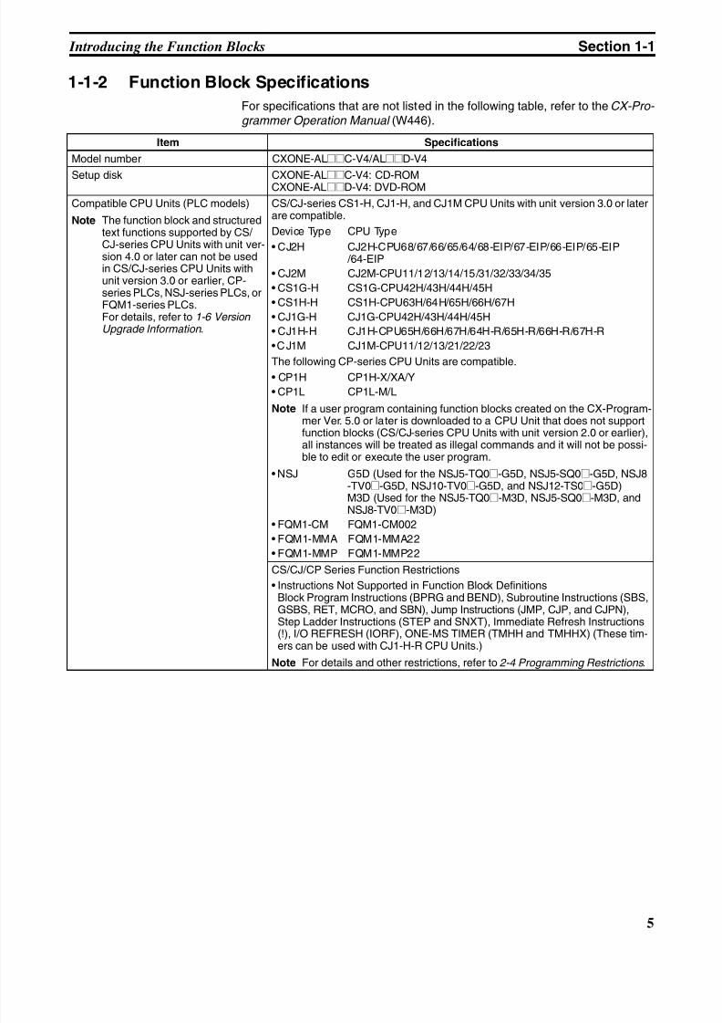
1-1-2 Function Block Specifications
For specifications that are not listed in the following table, refer to the CX-Pro- grammer Operation Manual (W446).
Item Specifications
Model number CXONE-AL@@C-V4/AL@@D-V4
Setup disk CXONE-AL@@C-V4: CD-ROMCXONE-AL@@D-V4: DVD-ROM
Compatible CPU Units (PLC models)
Note The function block and structuredtext functions supported by CS/ CJ-series CPU Units with unit ver-sion 4.0 or later can not be usedin CS/CJ-series CPU Units withunit version 3.0 or earlier, CP-series PLCs, NSJ-series PLCs, orFQM1-series PLCs.For details, refer to 1-6 VersionUpgrade Information .
CS/CJ-series CS1-H, CJ1-H, and CJ1M CPU Units with unit version 3.0 or laterare compatible.
Device Type CPU Type
• CJ2H CJ2H-CPU68/67/66/65/64/68-EIP/67-EIP/66-EIP/65-EIP /64-EIP
• CJ2M CJ2M-CPU11/12/13/14/15/31/32/33/34/35
• CS1G-H CS1G-CPU42H/43H/44H/45H
• CS1H-H CS1H-CPU63H/64H/65H/66H/67H
• CJ1G-H CJ1G-CPU42H/43H/44H/45H
• CJ1H-H CJ1H-CPU65H/66H/67H/64H-R/65H-R/66H-R/67H-R
•CJ1M CJ1M-CPU11/12/13/21/22/23
The following CP-series CPU Units are compatible.
• CP1H CP1H-X/XA/Y
• CP1L CP1L-M/L
Note If a user program containing function blocks created on the CX-Program-mer Ver. 5.0 or later is downloaded to a CPU Unit that does not supportfunction blocks (CS/CJ-series CPU Units with unit version 2.0 or earlier),all instances will be treated as illegal commands and it will not be possi-ble to edit or execute the user program.
• NSJ G5D (Used for the NSJ5-TQ0@-G5D, NSJ5-SQ0@-G5D, NSJ8-TV0@-G5D, NSJ10-TV0@-G5D, and NSJ12-TS0@-G5D)M3D (Used for the NSJ5-TQ0@-M3D, NSJ5-SQ0@-M3D, andNSJ8-TV0@-M3D)
• FQM1-CM FQM1-CM002
• FQM1-MMA FQM1-MMA22• FQM1-MMP FQM1-MMP22
CS/CJ/CP Series Function Restrictions
• Instructions Not Supported in Function Block DefinitionsBlock Program Instructions (BPRG and BEND), Subroutine Instructions (SBS,GSBS, RET, MCRO, and SBN), Jump Instructions (JMP, CJP, and CJPN),Step Ladder Instructions (STEP and SNXT), Immediate Refresh Instructions(!), I/O REFRESH (IORF), ONE-MS TIMER (TMHH and TMHHX) (These tim-ers can be used with CJ1-H-R CPU Units.)
Note For details and other restrictions, refer to 2-4 Programming Restrictions .
8/11/2019 CX-Programmer V9 Operation Manual FB ST.pdf
http://slidepdf.com/reader/full/cx-programmer-v9-operation-manual-fb-stpdf 32/254
6
Introducing the Function Blocks Section 1-1
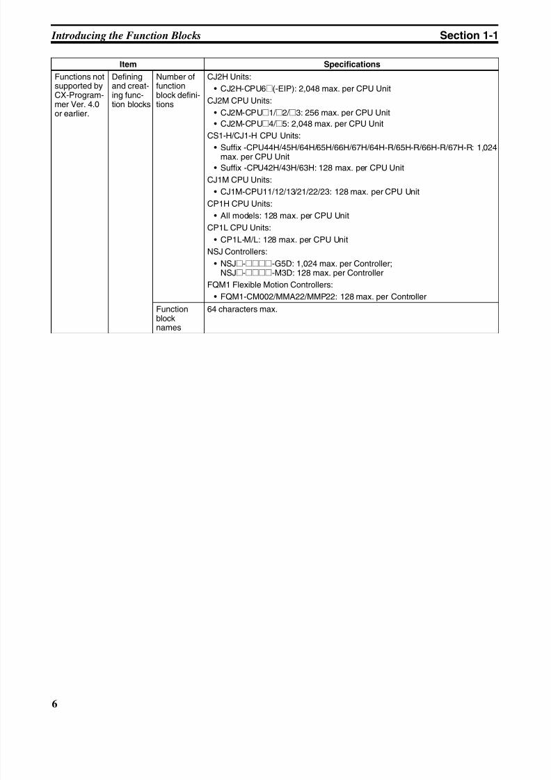
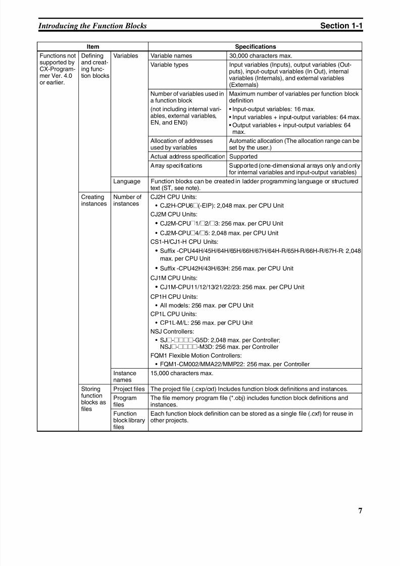
Functions notsupported byCX-Program-mer Ver. 4.0or earlier.
Definingand creat-ing func-tion blocks
Number offunctionblock defini-tions
CJ2H Units:
• CJ2H-CPU6@(-EIP): 2,048 max. per CPU Unit
CJ2M CPU Units:
• CJ2M-CPU@1/ @2/ @3: 256 max. per CPU Unit
• CJ2M-CPU@4/ @5: 2,048 max. per CPU Unit
CS1-H/CJ1-H CPU Units:• Suffix -CPU44H/45H/64H/65H/66H/67H/64H-R/65H-R/66H-R/67H-R: 1,024
max. per CPU Unit
• Suffix -CPU42H/43H/63H: 128 max. per CPU Unit
CJ1M CPU Units:
• CJ1M-CPU11/12/13/21/22/23: 128 max. per CPU Unit
CP1H CPU Units:
• All models: 128 max. per CPU Unit
CP1L CPU Units:
• CP1L-M/L: 128 max. per CPU Unit
NSJ Controllers:
• NSJ@-@@@@-G5D: 1,024 max. per Controller;
NSJ@-@@@@-M3D: 128 max. per ControllerFQM1 Flexible Motion Controllers:
• FQM1-CM002/MMA22/MMP22: 128 max. per Controller
Functionblocknames
64 characters max.
Item Specifications
8/11/2019 CX-Programmer V9 Operation Manual FB ST.pdf
http://slidepdf.com/reader/full/cx-programmer-v9-operation-manual-fb-stpdf 33/254
7
Introducing the Function Blocks Section 1-1
Functions notsupported byCX-Program-mer Ver. 4.0or earlier.
Definingand creat-ing func-tion blocks
Variables Variable names 30,000 characters max.
Variable types Input variables (Inputs), output variables (Out-puts), input-output variables (In Out), internalvariables (Internals), and external variables(Externals)
Number of variables used in
a function block(not including internal vari-ables, external variables,EN, and EN0)
Maximum number of variables per function block
definition• Input-output variables: 16 max.
• Input variables + input-output variables: 64 max.
• Output variables + input-output variables: 64max.
Allocation of addressesused by variables
Automatic allocation (The allocation range can beset by the user.)
Actual address specification Supported
Array specifications Supported (one-dimensional arrays only and onlyfor internal variables and input-output variables)
Language Function blocks can be created in ladder programming language or structuredtext (ST, see note).
Creatinginstances Number ofinstances CJ2H CPU Units:• CJ2H-CPU6@(-EIP): 2,048 max. per CPU Unit
CJ2M CPU Units:
• CJ2M-CPU@1/ @2/ @3: 256 max. per CPU Unit
• CJ2M-CPU@4/ @5: 2,048 max. per CPU Unit
CS1-H/CJ1-H CPU Units:
• Suffix -CPU44H/45H/64H/65H/66H/67H/64H-R/65H-R/66H-R/67H-R: 2,048
max. per CPU Unit
• Suffix -CPU42H/43H/63H: 256 max. per CPU Unit
CJ1M CPU Units:
• CJ1M-CPU11/12/13/21/22/23: 256 max. per CPU Unit
CP1H CPU Units:• All models: 256 max. per CPU Unit
CP1L CPU Units:
• CP1L-M/L: 256 max. per CPU Unit
NSJ Controllers:
• SJ@-@@@@-G5D: 2,048 max. per Controller;NSJ@-@@@@-M3D: 256 max. per Controller
FQM1 Flexible Motion Controllers:
• FQM1-CM002/MMA22/MMP22: 256 max. per Controller
Instancenames
15,000 characters max.
Storing
functionblocks asfiles
Project files The project file (.cxp/cxt) Includes function block definitions and instances.
Programfiles
The file memory program file (*.obj) includes function block definitions andinstances.
Functionblock libraryfiles
Each function block definition can be stored as a single file (.cxf) for reuse inother projects.
Item Specifications
8/11/2019 CX-Programmer V9 Operation Manual FB ST.pdf
http://slidepdf.com/reader/full/cx-programmer-v9-operation-manual-fb-stpdf 34/254
8
Introducing the Function Blocks Section 1-1
Note The structured text (ST language) conforms to the IEC 61131-3 standard, butCX-Programmer Ver. 5.0 supports only assignment statements, selectionstatements (CASE and IF statements), iteration statements (FOR, WHILE,REPEAT, and EXIT statements), RETURN statements, arithmetic operators,logical operators, comparison functions, numeric functions, standard stringfunctions, numeric string functions, OMRON expansion functions, and com-ments. For details, refer to SECTION 5 Structured Text (ST) Language Speci-
fications in Part 2: Structured Text (ST) .
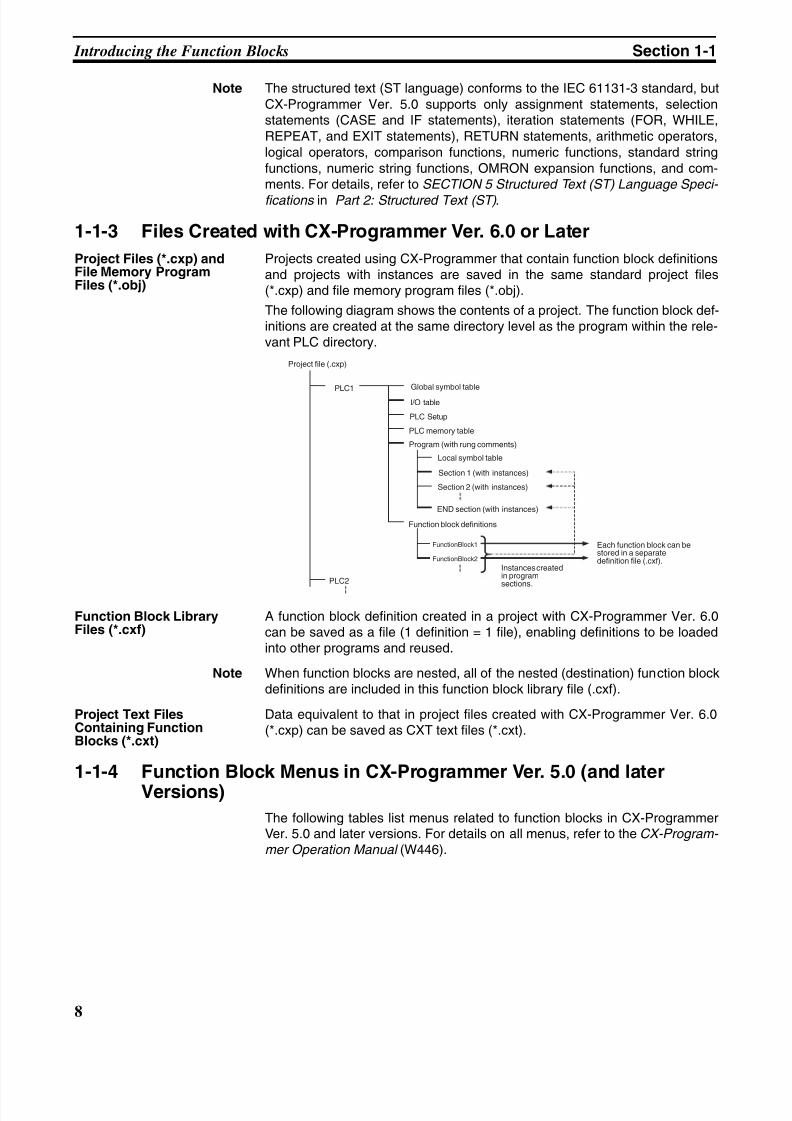
1-1-3 Files Created with CX-Programmer Ver. 6.0 or Later
Project Files (*.cxp) andFile Memory ProgramFiles (*.obj)
Projects created using CX-Programmer that contain function block definitionsand projects with instances are saved in the same standard project files(*.cxp) and file memory program files (*.obj).
The following diagram shows the contents of a project. The function block def-initions are created at the same directory level as the program within the rele-vant PLC directory.
Function Block LibraryFiles (*.cxf)
A function block definition created in a project with CX-Programmer Ver. 6.0can be saved as a file (1 definition = 1 file), enabling definitions to be loadedinto other programs and reused.
Note When function blocks are nested, all of the nested (destination) function blockdefinitions are included in this function block library file (.cxf).
Project Text FilesContaining FunctionBlocks (*.cxt)
Data equivalent to that in project files created with CX-Programmer Ver. 6.0(*.cxp) can be saved as CXT text files (*.cxt).
1-1-4 Function Block Menus in CX-Programmer Ver. 5.0 (and laterVersions)
The following tables list menus related to function blocks in CX-ProgrammerVer. 5.0 and later versions. For details on all menus, refer to the CX-Program- mer Operation Manual (W446).
FunctionBlock1
FunctionBlock2
Project file (.cxp)
PLC1
PLC2
Global symbol table
I/O table
PLC Setup
PLC memory table
Program (with rung comments)
Local symbol table
Section 1 (with instances)
Section 2 (with instances)
END section (with instances)
Function block definitions
Each function block can bestored in a separatedefinition file (.cxf).
Instances createdin programsections.
8/11/2019 CX-Programmer V9 Operation Manual FB ST.pdf
http://slidepdf.com/reader/full/cx-programmer-v9-operation-manual-fb-stpdf 35/254
9
Introducing the Function Blocks Section 1-1
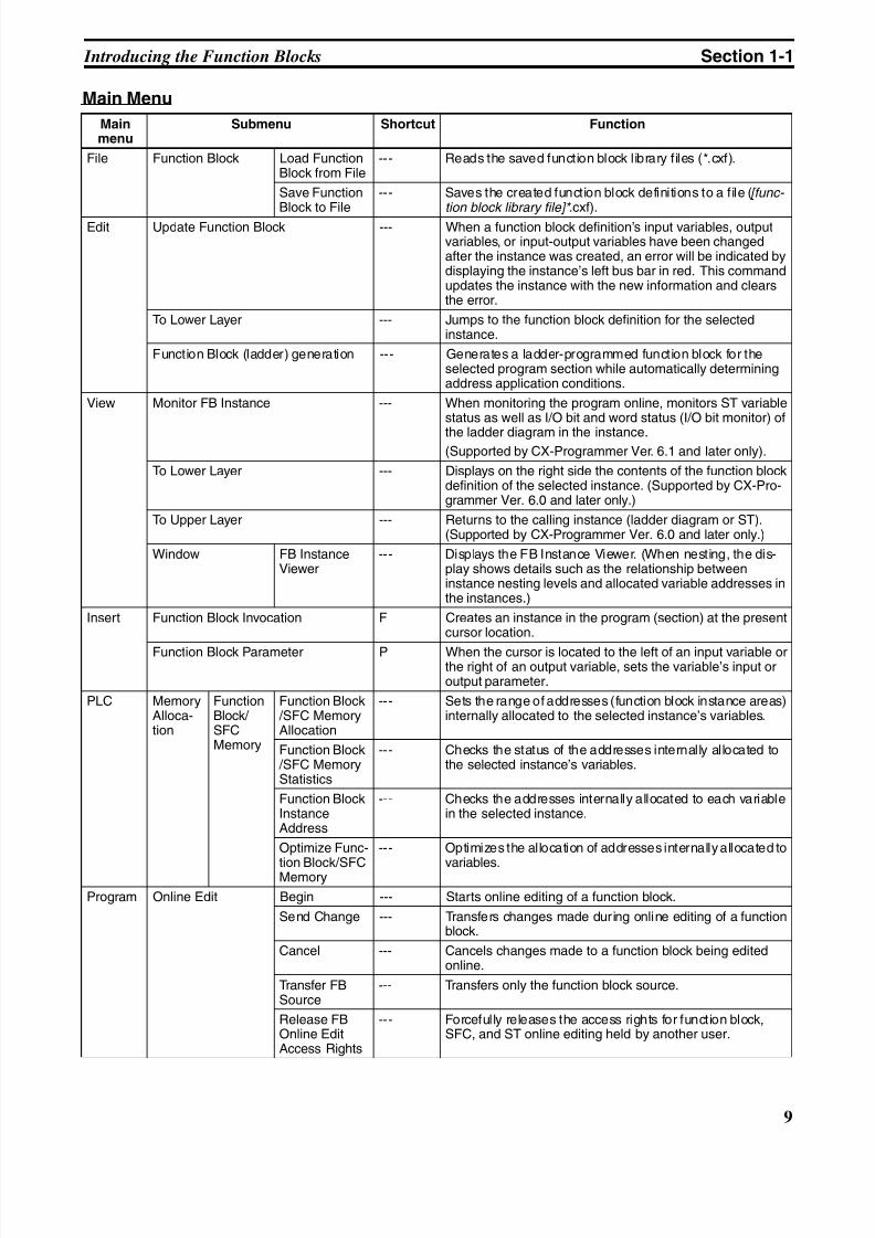
Main Menu
Mainmenu
Submenu Shortcut Function
File Function Block Load FunctionBlock from File
--- Reads the saved function block library files (*.cxf).
Save FunctionBlock to File
--- Saves the created function block definitions to a file ([func- tion block library file]* .cxf).
Edit Update Function Block --- When a function block definition’s input variables, outputvariables, or input-output variables have been changedafter the instance was created, an error will be indicated bydisplaying the instance’s left bus bar in red. This commandupdates the instance with the new information and clearsthe error.
To Lower Layer --- Jumps to the function block definition for the selectedinstance.
Function Block (ladder) generation --- Generates a ladder-programmed function block for theselected program section while automatically determiningaddress application conditions.
View Monitor FB Instance --- When monitoring the program online, monitors ST variablestatus as well as I/O bit and word status (I/O bit monitor) of
the ladder diagram in the instance.(Supported by CX-Programmer Ver. 6.1 and later only).
To Lower Layer --- Displays on the right side the contents of the function blockdefinition of the selected instance. (Supported by CX-Pro-grammer Ver. 6.0 and later only.)
To Upper Layer --- Returns to the calling instance (ladder diagram or ST).(Supported by CX-Programmer Ver. 6.0 and later only.)
Window FB InstanceViewer
--- Displays the FB Instance Viewer. (When nesting, the dis-play shows details such as the relationship betweeninstance nesting levels and allocated variable addresses inthe instances.)
Insert Function Block Invocation F Creates an instance in the program (section) at the presentcursor location.
Function Block Parameter P When the cursor is located to the left of an input variable orthe right of an output variable, sets the variable’s input oroutput parameter.
PLC MemoryAlloca-tion
FunctionBlock/ SFCMemory
Function Block /SFC MemoryAllocation
--- Sets the range of addresses (function block instance areas)internally allocated to the selected instance’s variables.
Function Block /SFC MemoryStatistics
--- Checks the status of the addresses internally allocated tothe selected instance’s variables.
Function BlockInstanceAddress
--- Checks the addresses internally allocated to each variablein the selected instance.
Optimize Func-
tion Block/SFCMemory
--- Optimizes the allocation of addresses internally allocated to
variables.
Program Online Edit Begin --- Starts online editing of a function block.
Send Change --- Transfers changes made during online editing of a functionblock.
Cancel --- Cancels changes made to a function block being editedonline.
Transfer FBSource
--- Transfers only the function block source.
Release FBOnline EditAccess Rights
--- Forcefully releases the access rights for function block,SFC, and ST online editing held by another user.
8/11/2019 CX-Programmer V9 Operation Manual FB ST.pdf
http://slidepdf.com/reader/full/cx-programmer-v9-operation-manual-fb-stpdf 36/254
10
Introducing the Function Blocks Section 1-1
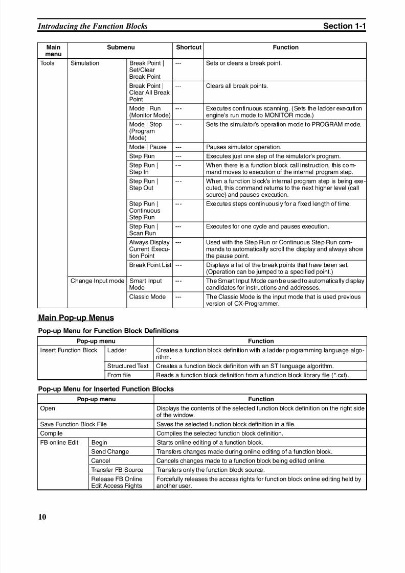
Main Pop-up Menus
Pop-up Menu for Function Block Definitions
Pop-up Menu for Inserted Function Blocks
Tools Simulation Break Point |Set/ClearBreak Point
--- Sets or clears a break point.
Break Point |Clear All Break
Point
--- Clears all break points.
Mode | Run(Monitor Mode)
--- Executes continuous scanning. (Sets the ladder executionengine’s run mode to MONITOR mode.)
Mode | Stop(ProgramMode)
--- Sets the simulator’s operation mode to PROGRAM mode.
Mode | Pause --- Pauses simulator operation.
Step Run --- Executes just one step of the simulator’s program.
Step Run |Step In
--- When there is a function block call instruction, this com-mand moves to execution of the internal program step.
Step Run |Step Out
--- When a function block’s internal program step is being exe-cuted, this command returns to the next higher level (callsource) and pauses execution.
Step Run |ContinuousStep Run
--- Executes steps continuously for a fixed length of time.
Step Run |Scan Run
--- Executes for one cycle and pauses execution.
Always DisplayCurrent Execu-tion Point
--- Used with the Step Run or Continuous Step Run com-mands to automatically scroll the display and always showthe pause point.
Break Point List --- Displays a list of the break points that have been set.(Operation can be jumped to a specified point.)
Change Input mode Smart InputMode
--- The Smart Input Mode can be used to automatically displaycandidates for instructions and addresses.
Classic Mode --- The Classic Mode is the input mode that is used previousversion of CX-Programmer.
Pop-up menu Function
Insert Function Block Ladder Creates a function block definition with a ladder programming language algo-rithm.
Structured Text Creates a function block definition with an ST language algorithm.
From file Reads a function block definition from a function block library file (*.cxf).
Pop-up menu FunctionOpen Displays the contents of the selected function block definition on the right side
of the window.
Save Function Block File Saves the selected function block definition in a file.
Compile Compiles the selected function block definition.
FB online Edit Begin Starts online editing of a function block.
Send Change Transfers changes made during online editing of a function block.
Cancel Cancels changes made to a function block being edited online.
Transfer FB Source Transfers only the function block source.
Release FB OnlineEdit Access Rights
Forcefully releases the access rights for function block online editing held byanother user.
Mainmenu
Submenu Shortcut Function
8/11/2019 CX-Programmer V9 Operation Manual FB ST.pdf
http://slidepdf.com/reader/full/cx-programmer-v9-operation-manual-fb-stpdf 37/254
11
Function Blocks Section 1-2
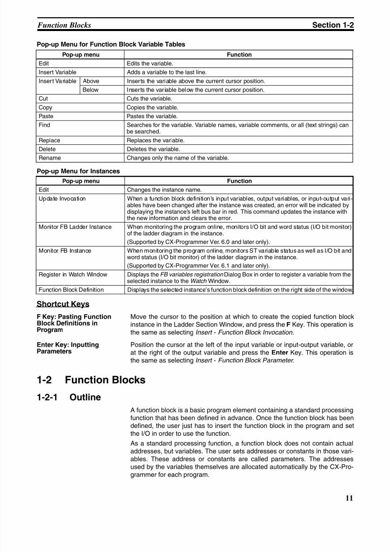
Pop-up Menu for Function Block Variable Tables
Pop-up Menu for Instances
Shortcut Keys
F Key: Pasting FunctionBlock Definitions inProgram
Move the cursor to the position at which to create the copied function blockinstance in the Ladder Section Window, and press the F Key. This operation isthe same as selecting Insert - Function Block Invocation.
Enter Key: InputtingParameters
Position the cursor at the left of the input variable or input-output variable, orat the right of the output variable and press the Enter Key. This operation isthe same as selecting Insert - Function Block Parameter.
1-2 Function Blocks
1-2-1 Outline
A function block is a basic program element containing a standard processingfunction that has been defined in advance. Once the function block has beendefined, the user just has to insert the function block in the program and setthe I/O in order to use the function.
As a standard processing function, a function block does not contain actualaddresses, but variables. The user sets addresses or constants in those vari-ables. These address or constants are called parameters. The addressesused by the variables themselves are allocated automatically by the CX-Pro-grammer for each program.
Pop-up menu Function
Edit Edits the variable.
Insert Variable Adds a variable to the last line.
Insert Variable Above Inserts the variable above the current cursor position.
Below Inserts the variable below the current cursor position.
Cut Cuts the variable.
Copy Copies the variable.
Paste Pastes the variable.
Find Searches for the variable. Variable names, variable comments, or all (text strings) canbe searched.
Replace Replaces the variable.
Delete Deletes the variable.
Rename Changes only the name of the variable.
Pop-up menu Function
Edit Changes the instance name.
Update Invocation When a function block definition’s input variables, output variables, or input-output vari-ables have been changed after the instance was created, an error will be indicated bydisplaying the instance’s left bus bar in red. This command updates the instance withthe new information and clears the error.
Monitor FB Ladder Instance When monitoring the program online, monitors I/O bit and word status (I/O bit monitor)of the ladder diagram in the instance.
(Supported by CX-Programmer Ver. 6.0 and later only).
Monitor FB Instance When monitoring the program online, monitors ST variable status as well as I/O bit andword status (I/O bit monitor) of the ladder diagram in the instance.
(Supported by CX-Programmer Ver. 6.1 and later only).
Register in Watch Window Displays the FB variables registration Dialog Box in order to register a variable from theselected instance to the Watch Window.
Function Block Definition Displays the selected instance’s function block definition on the right side of the window.
8/11/2019 CX-Programmer V9 Operation Manual FB ST.pdf
http://slidepdf.com/reader/full/cx-programmer-v9-operation-manual-fb-stpdf 38/254
12
Function Blocks Section 1-2
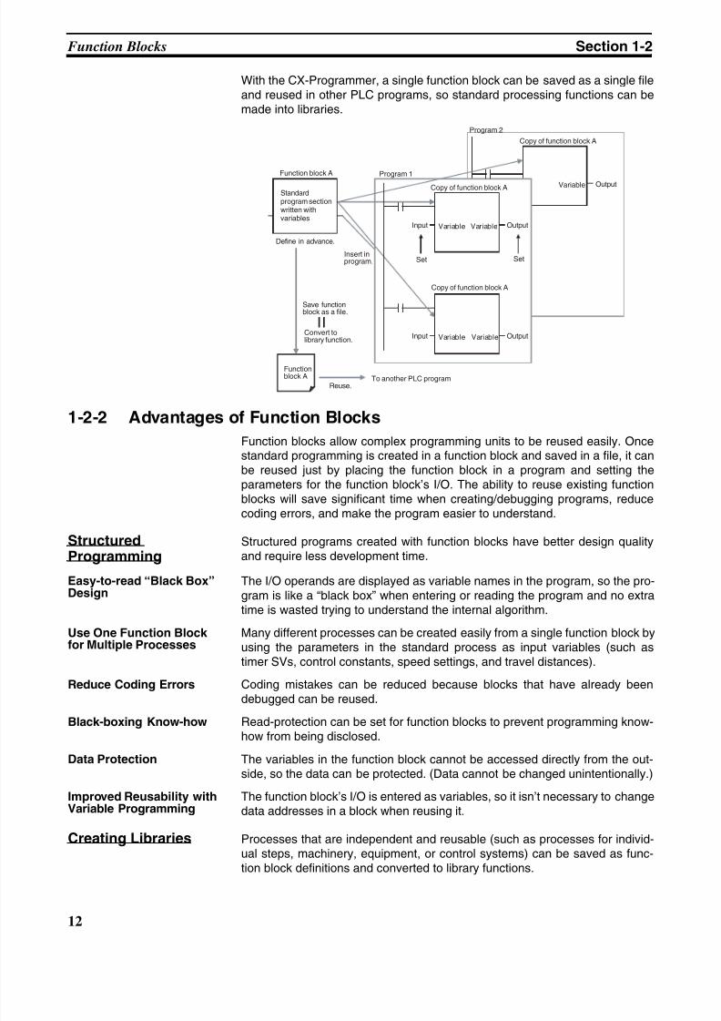
With the CX-Programmer, a single function block can be saved as a single fileand reused in other PLC programs, so standard processing functions can bemade into libraries.
1-2-2 Advantages of Function Blocks
Function blocks allow complex programming units to be reused easily. Oncestandard programming is created in a function block and saved in a file, it canbe reused just by placing the function block in a program and setting theparameters for the function block’s I/O. The ability to reuse existing functionblocks will save significant time when creating/debugging programs, reducecoding errors, and make the program easier to understand.
StructuredProgramming
Structured programs created with function blocks have better design qualityand require less development time.
Easy-to-read “Black Box”Design
The I/O operands are displayed as variable names in the program, so the pro-gram is like a “black box” when entering or reading the program and no extratime is wasted trying to understand the internal algorithm.
Use One Function Blockfor Multiple Processes
Many different processes can be created easily from a single function block byusing the parameters in the standard process as input variables (such astimer SVs, control constants, speed settings, and travel distances).
Reduce Coding Errors Coding mistakes can be reduced because blocks that have already beendebugged can be reused.
Black-boxing Know-how Read-protection can be set for function blocks to prevent programming know-how from being disclosed.
Data Protection The variables in the function block cannot be accessed directly from the out-side, so the data can be protected. (Data cannot be changed unintentionally.)
Improved Reusability withVariable Programming
The function block’s I/O is entered as variables, so it isn’t necessary to changedata addresses in a block when reusing it.
Creating Libraries Processes that are independent and reusable (such as processes for individ-ual steps, machinery, equipment, or control systems) can be saved as func-tion block definitions and converted to library functions.
Input Output
Input Output
Output
Function block A
Save functionblock as a file.
Program 2
Copy of function block A
Copy of function block A
Copy of function block A
Convert tolibrary function.
Functionblock A
Define in advance.
Insert inprogram.
Reuse.To another PLC program
Variable
Variable Variable
Set Set
Variable Variable
Program 1
Standardprogram sectionwritten withvariables
8/11/2019 CX-Programmer V9 Operation Manual FB ST.pdf
http://slidepdf.com/reader/full/cx-programmer-v9-operation-manual-fb-stpdf 39/254
13
Function Blocks Section 1-2
The function blocks are created with variable names that are not tied to actualaddresses, so new programs can be developed easily just by reading the def-initions from the file and placing them in a new program.
Supports Nesting andMultiple Languages
Mathematical expressions can be entered in structured text (ST) language.
With CX-Programmer Ver. 6.0 and later versions, function blocks can benested. The function block nesting function allows just special processing tobe performed in a ST-language function block nested within a ladder-lan-guage function block.
1-2-3 Function Block Structure
Function blocks consist of function block definitions that are created inadvance and function block instances that are inserted in the program.
Function BlockDefinitions
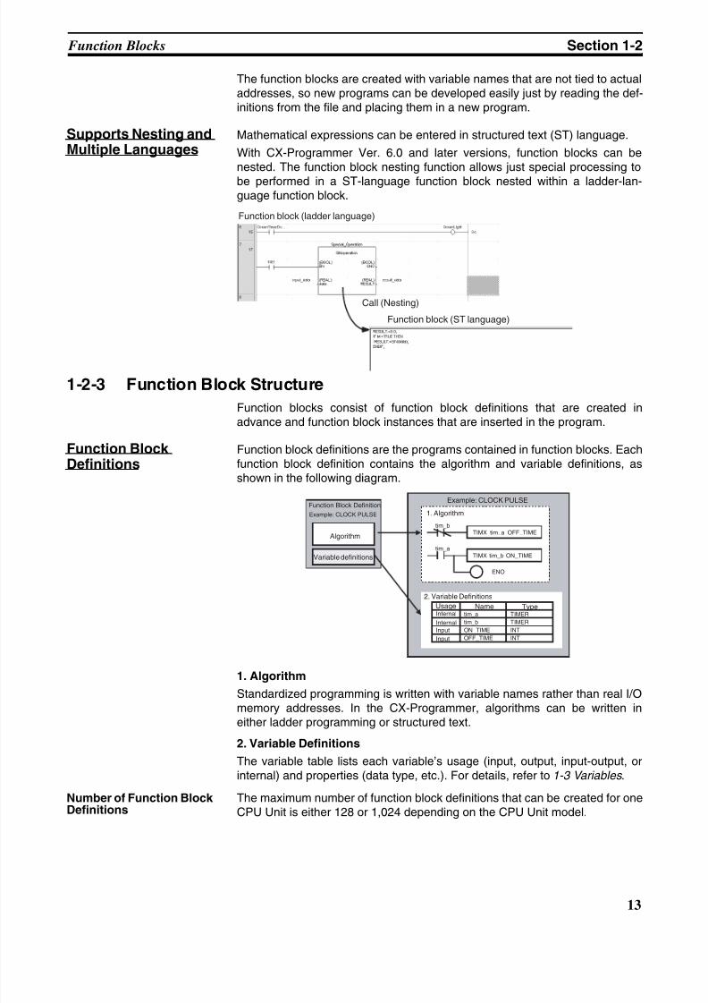
Function block definitions are the programs contained in function blocks. Eachfunction block definition contains the algorithm and variable definitions, asshown in the following diagram.
1. Algorithm
Standardized programming is written with variable names rather than real I/Omemory addresses. In the CX-Programmer, algorithms can be written ineither ladder programming or structured text.
2. Variable Definitions
The variable table lists each variable’s usage (input, output, input-output, orinternal) and properties (data type, etc.). For details, refer to 1-3 Variables .
Number of Function BlockDefinitions
The maximum number of function block definitions that can be created for oneCPU Unit is either 128 or 1,024 depending on the CPU Unit model.
Function block (ladder language)
Call (Nesting)
Function block (ST language)
tim_a TIMER
tim_b TIMER
ON_TIME INT
OFF_TIME INT
TIMX tim_a OFF_TIMEtim_b
TIMX tim_b ON_TIMEtim_a
ENO
Name TypeInternal
InternalInput
Input
Function Block Definition
Example: CLOCK PULSE
Algorithm
Example: CLOCK PULSE
1. Algorithm
2. Variable Definitions
Variable definitions
Usage
8/11/2019 CX-Programmer V9 Operation Manual FB ST.pdf
http://slidepdf.com/reader/full/cx-programmer-v9-operation-manual-fb-stpdf 40/254
14
Function Blocks Section 1-2
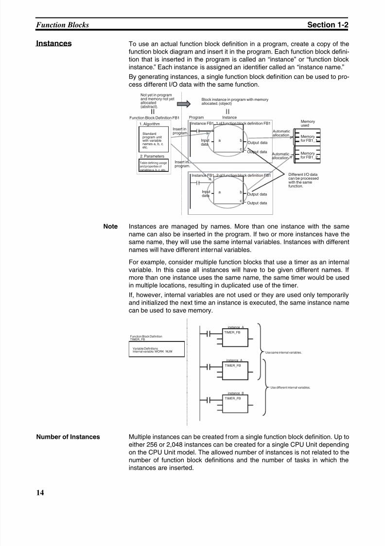
Instances To use an actual function block definition in a program, create a copy of thefunction block diagram and insert it in the program. Each function block defini-tion that is inserted in the program is called an “instance” or “function blockinstance.” Each instance is assigned an identifier called an “instance name.”
By generating instances, a single function block definition can be used to pro-cess different I/O data with the same function.
Note Instances are managed by names. More than one instance with the samename can also be inserted in the program. If two or more instances have thesame name, they will use the same internal variables. Instances with differentnames will have different internal variables.
For example, consider multiple function blocks that use a timer as an internalvariable. In this case all instances will have to be given different names. Ifmore than one instance uses the same name, the same timer would be used
in multiple locations, resulting in duplicated use of the timer.If, however, internal variables are not used or they are used only temporarilyand initialized the next time an instance is executed, the same instance namecan be used to save memory.
Number of Instances Multiple instances can be created from a single function block definition. Up toeither 256 or 2,048 instances can be created for a single CPU Unit dependingon the CPU Unit model. The allowed number of instances is not related to thenumber of function block definitions and the number of tasks in which theinstances are inserted.
a b
c
a b
c
Not yet in programand memory not yetallocated(abstract).
1. Algorithm
Function Block Definition FB1
2. Parameters
Standardprogram unitwith variablenames a, b, c,etc.
Program Instance
Block instance in program with memoryallocated. (object)
Instance FB1_1 of function block definition FB1Memoryused
Inputdata Output data
Output data
Automaticallocation
Automaticallocation
Memoryfor FB1_1
Memoryfor FB1_2
Different I/O datacan be processedwith the samefunction.
Instance FB1_2 of function block definition FB1
Inputdata Output data
Output data
Insert inprogram.
Insert inprogram.
Table defining usageand properties ofvariables a, b, c, etc.
TIMER_FB
TIMER_FB
TIMER_FB
instance_A
instance_A
instance_B
Function Block DefinitionTIMER_FB
Variable DefinitionsInternal variable: WORK_NUM Use same internal variables.
Use different internal variables.
8/11/2019 CX-Programmer V9 Operation Manual FB ST.pdf
http://slidepdf.com/reader/full/cx-programmer-v9-operation-manual-fb-stpdf 41/254
15
Function Blocks Section 1-2
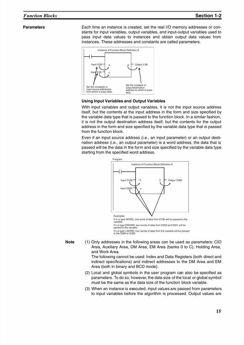
Parameters Each time an instance is created, set the real I/O memory addresses or con-stants for input variables, output variables, and input-output variables used topass input data values to instances and obtain output data values frominstances. These addresses and constants are called parameters.
Using Input Variables and Output Variables
With input variables and output variables, it is not the input source addressitself, but the contents at the input address in the form and size specified bythe variable data type that is passed to the function block. In a similar fashion,
it is not the output destination address itself, but the contents for the outputaddress in the form and size specified by the variable data type that is passedfrom the function block.
Even if an input source address (i.e., an input parameter) or an output desti-nation address (i.e., an output parameter) is a word address, the data that ispassed will be the data in the form and size specified by the variable data typestarting from the specified word address.
Note (1) Only addresses in the following areas can be used as parameters: CIOArea, Auxiliary Area, DM Area, EM Area (banks 0 to C), Holding Area,and Work Area.The following cannot be used: Index and Data Registers (both direct andindirect specifications) and indirect addresses to the DM Area and EMArea (both in binary and BCD mode).
(2) Local and global symbols in the user program can also be specified asparameters. To do so, however, the data size of the local or global symbolmust be the same as the data size of the function block variable.
(3) When an instance is executed, input values are passed from parametersto input variables before the algorithm is processed. Output values are
a b
c
Input 0.00
Instance of Function Block Definition A
Input 3.00
Output 2.00
Set the constants orinput source addressesfrom which to pass data.
Set the constant oroutput destinationaddress to which to passdata.
m k
n
Examples:
If m is type WORD, one word of data from D100 will be passed to thevariable.
If n is type DWORD, two words of data from D200 and D201 will bepassed to the variable.
If k is type LWORD, four words of data from the variable will be passedto the D300 to D303.
Program
Input D100
Instance of Function Block Definition A
Output D300
Input D200
8/11/2019 CX-Programmer V9 Operation Manual FB ST.pdf
http://slidepdf.com/reader/full/cx-programmer-v9-operation-manual-fb-stpdf 42/254
16
Function Blocks Section 1-2
passed from output variables to parameters just after processing the al-gorithm. If it is necessary to read or write a value within the execution cy-cle of the algorithm, do not pass the value to or from a parameter. Assignthe value to an internal variable and use an AT setting (specified address-es).
!Caution If an address is specified in an input parameter, the values in the address are
passed to the input variable. The actual address data itself cannot be passed.
!Caution Parameters cannot be used to read or write values within the execution cycleof the algorithm. Use an internal variable with an AT setting (specifiedaddresses). Alternatively, reference a global symbol as an external variable.
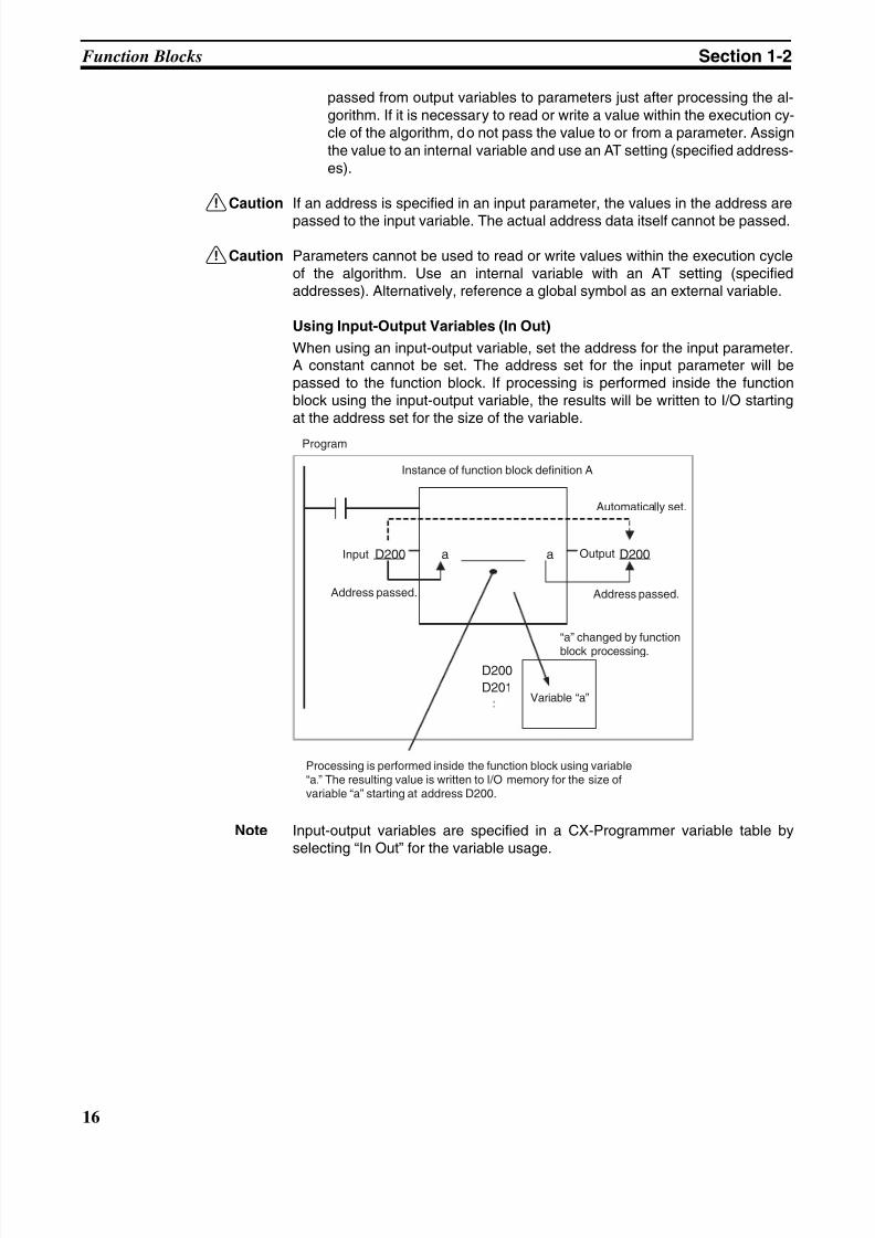
Using Input-Output Variables (In Out)
When using an input-output variable, set the address for the input parameter.A constant cannot be set. The address set for the input parameter will bepassed to the function block. If processing is performed inside the functionblock using the input-output variable, the results will be written to I/O startingat the address set for the size of the variable.
Note Input-output variables are specified in a CX-Programmer variable table byselecting “In Out” for the variable usage.
D200 D200a a
D200
D201
Processing is performed inside the function block using variable“a.” The resulting value is written to I/O memory for the size ofvariable “a” starting at address D200.
Program
Instance of function block definition A
Input
Address passed.
Automatically set.
Output
Address passed.
“a” changed by function
block processing.
Variable “a”
8/11/2019 CX-Programmer V9 Operation Manual FB ST.pdf
http://slidepdf.com/reader/full/cx-programmer-v9-operation-manual-fb-stpdf 43/254
17
Function Blocks Section 1-2
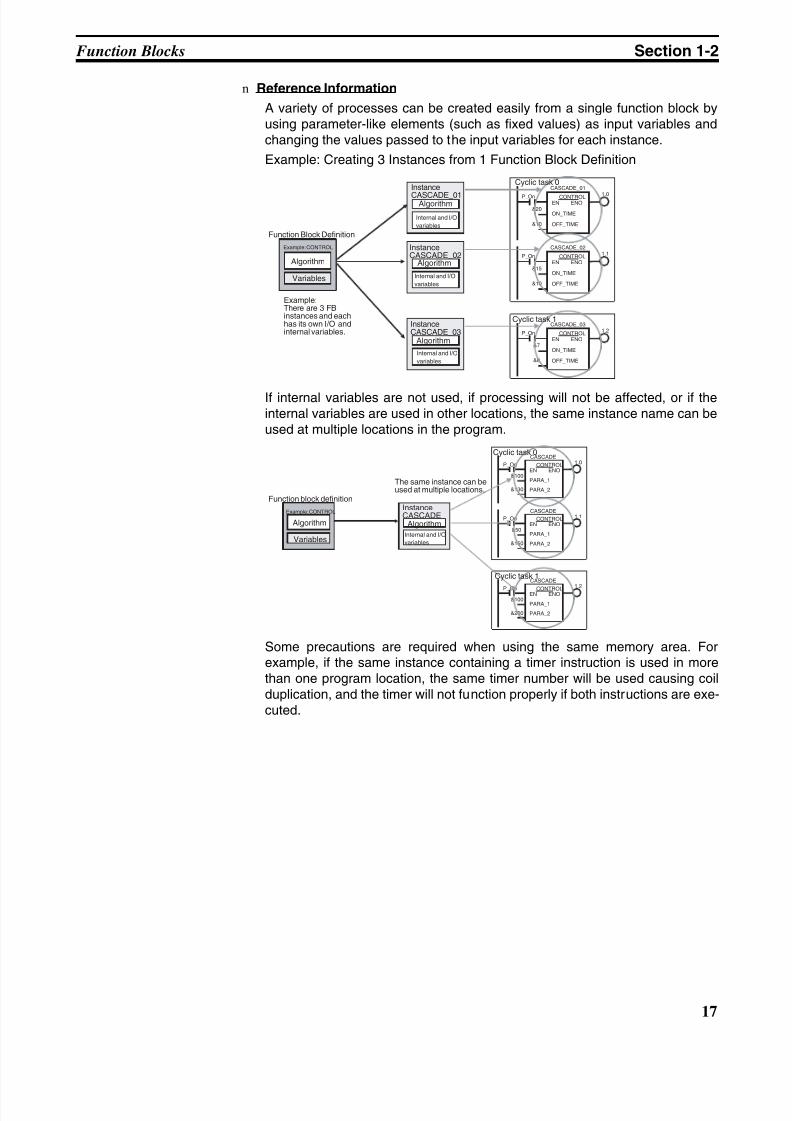
n Reference Information
A variety of processes can be created easily from a single function block byusing parameter-like elements (such as fixed values) as input variables andchanging the values passed to the input variables for each instance.
Example: Creating 3 Instances from 1 Function Block Definition
If internal variables are not used, if processing will not be affected, or if theinternal variables are used in other locations, the same instance name can beused at multiple locations in the program.
Some precautions are required when using the same memory area. Forexample, if the same instance containing a timer instruction is used in morethan one program location, the same timer number will be used causing coilduplication, and the timer will not function properly if both instructions are exe-cuted.
P_On 1.0
&10
CONTROLEN ENO
ON_TIME
OFF_TIME
&20
CASCADE_01
P_On 1.1
&10
CONTROLEN ENO
ON_TIME
OFF_TIME
&15
CASCADE_02
P_On 1.2
&8
CONTROLEN ENO
ON_TIME
OFF_TIME
&7
CASCADE_03
Function Block Definition
Example: CONTROL
Algorithm
Variables
InstanceCASCADE_02
Algorithm
Internal and I/O
variables
Instance
CASCADE_01Algorithm
Internal and I/O
variables
InstanceCASCADE_03
Algorithm
Internal and I/O
variables
Cyclic task 0
Cyclic task 1
Example:There are 3 FBinstances and eachhas its own I/O andinternal variables.
P_On 1.0
&130
CONTROLEN ENO
PARA_1
PARA_2
&100
CASCADE
P_On 1.1
&150
CONTROLEN ENO
PARA_1
PARA_2
&50
CASCADE
P_On1.2
&200
CONTROLEN ENO
PARA_1
PARA_2
&100
CASCADE
Function block definition
Example: CONTROL
Algorithm
Variables
InstanceCASCADE
Algorithm
Internal and I/O
variables
Cyclic task 0
Cyclic task 1
The same instance can beused at multiple locations.
8/11/2019 CX-Programmer V9 Operation Manual FB ST.pdf
http://slidepdf.com/reader/full/cx-programmer-v9-operation-manual-fb-stpdf 44/254
18
Variables Section 1-3
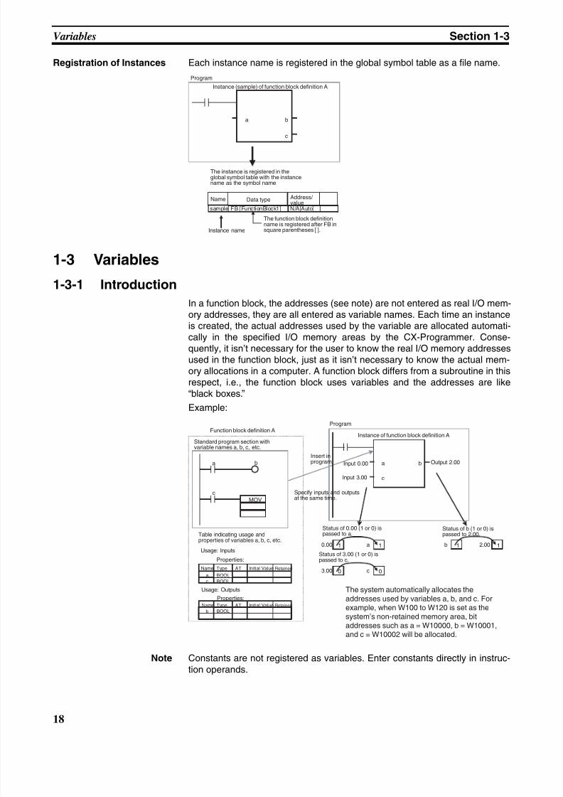
Registration of Instances Each instance name is registered in the global symbol table as a file name.
1-3 Variables
1-3-1 Introduction
In a function block, the addresses (see note) are not entered as real I/O mem-ory addresses, they are all entered as variable names. Each time an instanceis created, the actual addresses used by the variable are allocated automati-cally in the specified I/O memory areas by the CX-Programmer. Conse-quently, it isn’t necessary for the user to know the real I/O memory addressesused in the function block, just as it isn’t necessary to know the actual mem-ory allocations in a computer. A function block differs from a subroutine in thisrespect, i.e., the function block uses variables and the addresses are like“black boxes.”
Example:
Note Constants are not registered as variables. Enter constants directly in instruc-tion operands.
a b
c
sample FB [FunctionBlock1] N/A[Auto]
Program
Instance (sample) of function block definition A
The instance is registered in theglobal symbol table with the instancename as the symbol name.
Name Data type Address/value
The function block definitionname is registered after FB insquare parentheses [ ].Instance name
a b
c
MOV
a
c
b
Name Type AT Initial Value Retained
a BOOL
c BOOL
Name Type AT Initial Value Retained
b BOOL
0.00 a1 1
3.00 c0 0
2.00b 11
Input 0.00
Instance of function block definition A
Input 3.00
Output 2.00
Function block definition A
Standard program section withvariable names a, b, c, etc.
Insert inprogram.
Specify inputs and outputsat the same time.
Table indicating usage andproperties of variables a, b, c, etc.
Usage: Inputs
Properties:
Usage: Outputs
Properties:
Status of 0.00 (1 or 0) ispassed to a.
Status of b (1 or 0) ispassed to 2.00.
Status of 3.00 (1 or 0) ispassed to c.
Program
The system automatically allocates theaddresses used by variables a, b, and c. Forexample, when W100 to W120 is set as thesystem’s non-retained memory area, bitaddresses such as a = W10000, b = W10001,and c = W10002 will be allocated.
8/11/2019 CX-Programmer V9 Operation Manual FB ST.pdf
http://slidepdf.com/reader/full/cx-programmer-v9-operation-manual-fb-stpdf 45/254
19
Variables Section 1-3
• Ladder programming language: Enter hexadecimal numerical valuesafter the # and decimal values after the &.
• Structured text (ST language): Enter hexadecimal numerical values af-ter 16# and enter decimal numerical values as is.
Exception: Enter directly or indirectly specified addresses for Index RegistersIR0 to IR15 and Data Registers DR0 to DR15 directly into the instruction
operand.
1-3-2 Variable Usage and Properties
Variable Usage The following variable types (usages) are supported.
Internals: Internal variables are used only within an instance. They cannotbe used pass data directly to or from I/O parameters.
Inputs: Input variables can input data from input parameters outside ofthe instance. The default input variable is an EN (Enable) vari-able, which passes input condition data.
Outputs: Output variables can output data to output parameters outside ofthe instance. The default output variable is an ENO (Enable Out)
variable, which passes the instance’s execution status.In Out: Input-output variables can input data from input parameters out-
side of the instance and can return the results of processing in afunction block instance to external parameters.
Externals: External variables are either system-defined variables registeredin advance with the CX-Programmer, such as the Condition Flagsand some Auxiliary Area bits, or user-defined global symbols foruse within instances.
For details on variable usage, refer to the section on Variable Type (Usage) under Variable Definitions in 2-1-2 Function Block Elements .
The following table shows the number of variables that can be used and thekind of variable that is created by default for each of the variable usages.
1-3-3 Variable Properties
Variables have the following properties.
Variable Name The variable name is used to identify the variable in the function block. Itdoesn’t matter if the same name is used in other function blocks.
Note The variable name can be up to 30,000 characters long, but must not beginwith a number. Also, the name cannot contain two underscore characters in arow. The character string cannot be the same as that of a an index registersuch as in IR0 to IR15. For details on other restrictions, refer to Variable Defi- nitions in 2-1-2 Function Block Elements .
Data Type Select one of the following data types for the variable:
BOOL, INT, UINT, DINT, UDINT, LINT, ULINT, WORD, DWORD, LWORD,REAL, LREAL, TIMER, COUNTER, and STRING
For details on variable data types, refer to Variable Definitions in 2-1-2 Func- tion Block Elements .
AT Settings (Allocation toan Actual Addresses)
It is possible to set a variable to a particular I/O memory address rather thanhaving it allocated automatically by the system. To specify a particularaddress, the user can input the desired I/O memory address in this property.This property can be set for internal variables only. Even if a specific addressis set, the variable name must still be used in the algorithm.
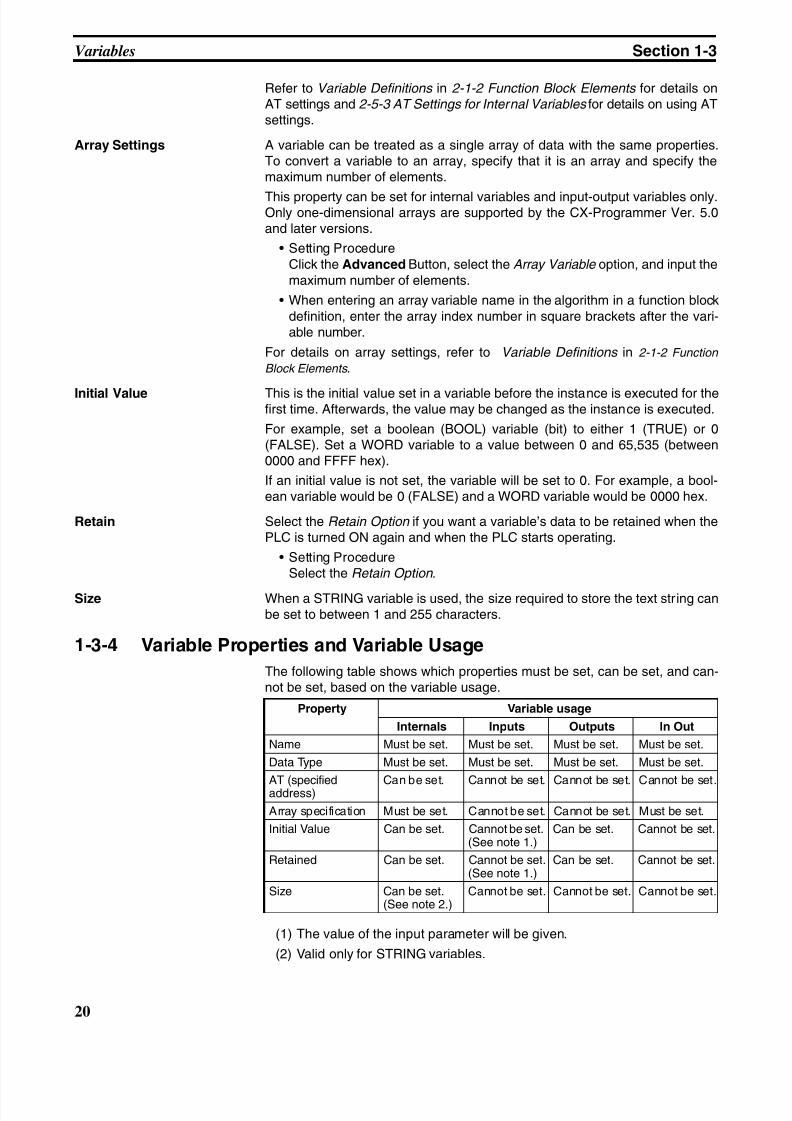
8/11/2019 CX-Programmer V9 Operation Manual FB ST.pdf
http://slidepdf.com/reader/full/cx-programmer-v9-operation-manual-fb-stpdf 46/254
20
Variables Section 1-3
Refer to Variable Definitions in 2-1-2 Function Block Elements for details onAT settings and 2-5-3 AT Settings for Internal Variables for details on using ATsettings.
Array Settings A variable can be treated as a single array of data with the same properties.To convert a variable to an array, specify that it is an array and specify themaximum number of elements.
This property can be set for internal variables and input-output variables only.Only one-dimensional arrays are supported by the CX-Programmer Ver. 5.0and later versions.
• Setting ProcedureClick the Advanced Button, select the Array Variable option, and input themaximum number of elements.
• When entering an array variable name in the algorithm in a function blockdefinition, enter the array index number in square brackets after the vari-able number.
For details on array settings, refer to Variable Definitions in 2-1-2 Function
Block Elements .
Initial Value This is the initial value set in a variable before the instance is executed for thefirst time. Afterwards, the value may be changed as the instance is executed.
For example, set a boolean (BOOL) variable (bit) to either 1 (TRUE) or 0(FALSE). Set a WORD variable to a value between 0 and 65,535 (between0000 and FFFF hex).
If an initial value is not set, the variable will be set to 0. For example, a bool-ean variable would be 0 (FALSE) and a WORD variable would be 0000 hex.
Retain Select the Retain Option if you want a variable’s data to be retained when thePLC is turned ON again and when the PLC starts operating.
• Setting ProcedureSelect the Retain Option .
Size When a STRING variable is used, the size required to store the text string canbe set to between 1 and 255 characters.
1-3-4 Variable Properties and Variable Usage
The following table shows which properties must be set, can be set, and can-not be set, based on the variable usage.
(1) The value of the input parameter will be given.
(2) Valid only for STRING variables.
Property Variable usage
Internals Inputs Outputs In Out
Name Must be set. Must be set. Must be set. Must be set.
Data Type Must be set. Must be set. Must be set. Must be set.
AT (specifiedaddress) Can be set. Cannot be set. Cannot be set. Cannot be set.
Array specification Must be set. Cannot be set. Cannot be set. Must be set.
Initial Value Can be set. Cannot be set.(See note 1.)
Can be set. Cannot be set.
Retained Can be set. Cannot be set.(See note 1.)
Can be set. Cannot be set.
Size Can be set.(See note 2.)
Cannot be set. Cannot be set. Cannot be set.
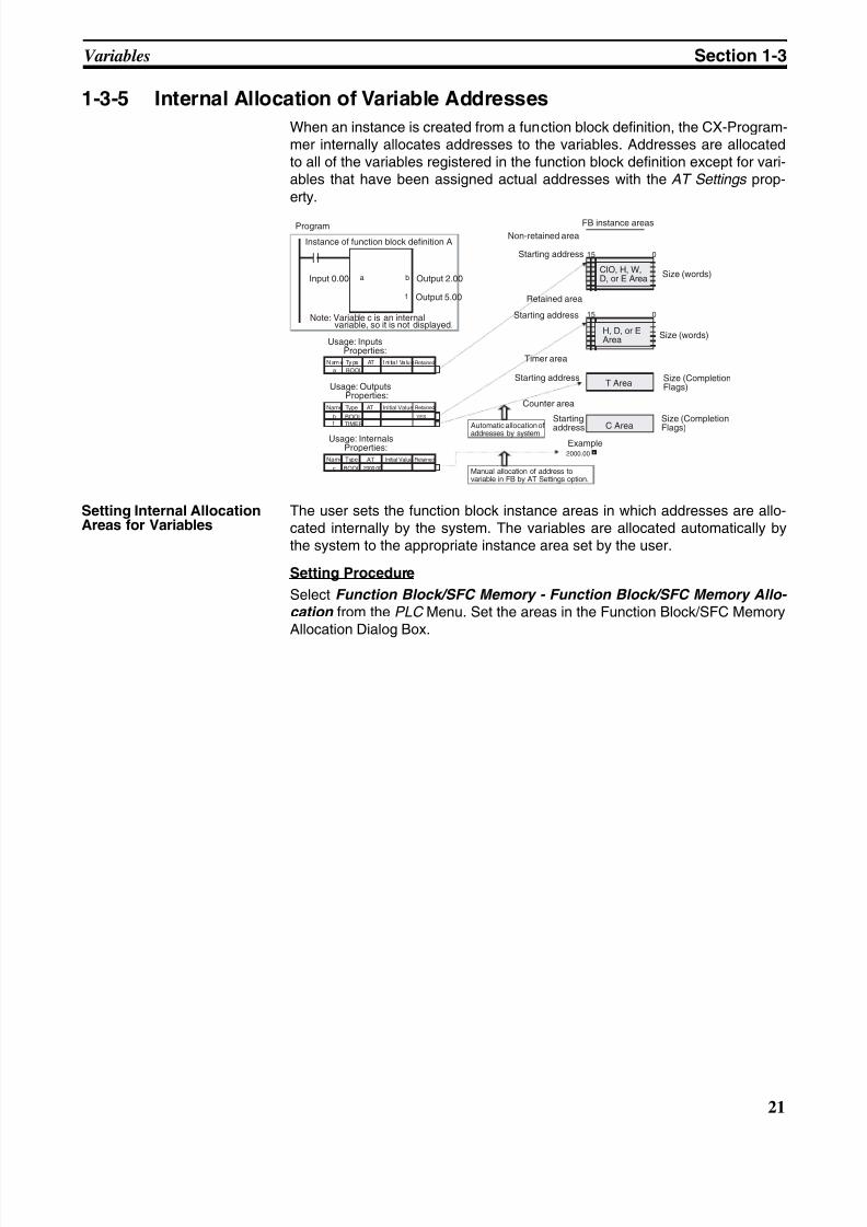
8/11/2019 CX-Programmer V9 Operation Manual FB ST.pdf
http://slidepdf.com/reader/full/cx-programmer-v9-operation-manual-fb-stpdf 47/254
21
Variables Section 1-3
1-3-5 Internal Allocation of Variable Addresses
When an instance is created from a function block definition, the CX-Program-mer internally allocates addresses to the variables. Addresses are allocatedto all of the variables registered in the function block definition except for vari-ables that have been assigned actual addresses with the AT Settings prop-erty.
Setting Internal AllocationAreas for Variables
The user sets the function block instance areas in which addresses are allo-cated internally by the system. The variables are allocated automatically bythe system to the appropriate instance area set by the user.
Setting Procedure
Select Function Block/SFC Memory - Function Block/SFC Memory Allo- cation from the PLC Menu. Set the areas in the Function Block/SFC MemoryAllocation Dialog Box.
a b
15 0
15 0
t
N am e Ty pe AT I ni tia l Va lu eRetained
a BOOL
Name Type AT
b YES
t TIMER
2000.00Name Type Initial Value
c 2000.00
Initial Value Retained
RetainedAT
BOOL
BOOL
Input 0.00
Instance of function block definition A
Output 2.00
Output 5.00
Note: Variable c is an internalvariable, so it is not displayed.
Usage: InputsProperties:
Usage: OutputsProperties:
Usage: InternalsProperties:
Automatic allocation ofaddresses by system
Manual allocation of address tovariable in FB by AT Settings option.
Program FB instance areas
Size (words)
Non-retained area
Retained area
Starting address
Starting address
Starting address
Starting
address
Timer area
Counter area
CIO, H, W,D, or E Area
H, D, or EArea
T Area
C Area
Size (words)
Size (CompletionFlags)
Size (Completion
Flags)Example
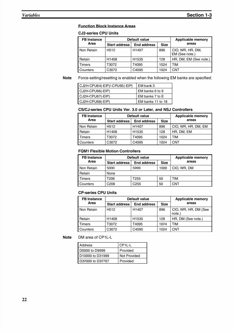
8/11/2019 CX-Programmer V9 Operation Manual FB ST.pdf
http://slidepdf.com/reader/full/cx-programmer-v9-operation-manual-fb-stpdf 48/254
22
Variables Section 1-3
Function Block Instance Areas
CJ2-series CPU Units
Note Force-setting/resetting is enabled when the following EM banks are specified:
CS/CJ-series CPU Units Ver. 3.0 or Later, and NSJ Controllers
FQM1 Flexible Motion Controllers
CP-series CPU Units
Note DM area of CP1L-L
FB InstanceArea
Default value Applicable memoryareasStart address End address Size
Non Retain H512 H1407 896 CIO, WR, HR, DM,EM (See note.)
Retain H1408 H1535 128 HR, DM, EM (See note.)
Timers T3072 T4095 1024 TIM
Counters C3072 C4095 1024 CNT
CJ2H-CPU64(-EIP)/-CPU65(-EIP) EM bank 3
CJ2H-CPU66(-EIP) EM banks 6 to 9
CJ2H-CPU67(-EIP) EM banks 7 to E
CJ2H-CPU68(-EIP) EM banks 11 to 18
FB InstanceArea
Default value Applicable memoryareasStart address End address Size
Non Retain H512 H1407 896 CIO, WR, HR, DM, EM
Retain H1408 H1535 128 HR, DM, EM
Timers T3072 T4095 1024 TIM
Counters C3072 C4095 1024 CNT
FB InstanceArea
Default value Applicable memoryareasStart address End address Size
Non Retain 5000 5999 1000 CIO, WR, DM
Retain NoneTimers T206 T255 50 TIM
Counters C206 C255 50 CNT
FB InstanceArea
Default value Applicable memoryareasStart address End address Size
Non Retain H512 H1407 896 CIO, WR, HR, DM (Seenote.)
Retain H1408 H1535 128 HR, DM (See note.)
Timers T3072 T4095 1024 TIM
Counters C3072 C4095 1024 CNT
Address CP1L-L
D0000 to D9999 Provided
D10000 to D31999 Not Provided
D32000 to D32767 Provided
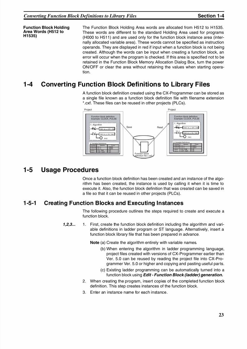
8/11/2019 CX-Programmer V9 Operation Manual FB ST.pdf
http://slidepdf.com/reader/full/cx-programmer-v9-operation-manual-fb-stpdf 49/254
23
Converting Function Block Definitions to Library Files Section 1-4
Function Block HoldingArea Words (H512 toH1535)
The Function Block Holding Area words are allocated from H512 to H1535.These words are different to the standard Holding Area used for programs(H000 to H511) and are used only for the function block instance area (inter-nally allocated variable area). These words cannot be specified as instructionoperands. They are displayed in red if input when a function block is not beingcreated. Although the words can be input when creating a function block, anerror will occur when the program is checked. If this area is specified not to be
retained in the Function Block Memory Allocation Dialog Box, turn the powerON/OFF or clear the area without retaining the values when starting opera-tion.
1-4 Converting Function Block Definitions to Library Files
A function block definition created using the CX-Programmer can be stored asa single file known as a function block definition file with filename extension*.cxf. These files can be reused in other projects (PLCs).
1-5 Usage Procedures
Once a function block definition has been created and an instance of the algo-
rithm has been created, the instance is used by calling it when it is time toexecute it. Also, the function block definition that was created can be saved ina file so that it can be reused in other projects (PLCs).
1-5-1 Creating Function Blocks and Executing Instances
The following procedure outlines the steps required to create and execute afunction block.
1,2,3... 1. First, create the function block definition including the algorithm and vari-able definitions in ladder program or ST language. Alternatively, insert afunction block library file that has been prepared in advance.
Note (a) Create the algorithm entirely with variable names.(b) When entering the algorithm in ladder programming language,
project files created with versions of CX-Programmer earlier thanVer. 5.0 can be reused by reading the project file into CX-Pro-grammer Ver. 5.0 or higher and copying and pasting useful parts.
(c) Existing ladder programming can be automatically turned into afunction block using Edit - Function Block (ladder) generation.
2. When creating the program, insert copies of the completed function blockdefinition. This step creates instances of the function block.
3. Enter an instance name for each instance.
tim_b
tim_a
ENO
TIMX tim_a OFF_TIMEtim_b
TIMX tim_b ON_TIMEtim_a
ENO
Project Project
Save Read
Function block definitionExample: CLOCK_PULSE
Function block definitionExample: CLOCK_PULSE
1. Algorithm1. Algorithm
Function blockdefinition file (.cxf)
TIMX tim_a OFF_TIME
TIMX tim_b ON_TIME
tim_a TIMER
tim_b TIMER
ON_ TI ME I NT
OFF_TIME INT
Name TypeInternal
Internal
Input
Input
2. Variable Definitions
Usage tim_a TIMER
tim_b TIMER
ON_ TI ME I NT
OFF_TIME INT
Name TypeInternal
InternalInput
Input
2. Variable Definitions
Usage
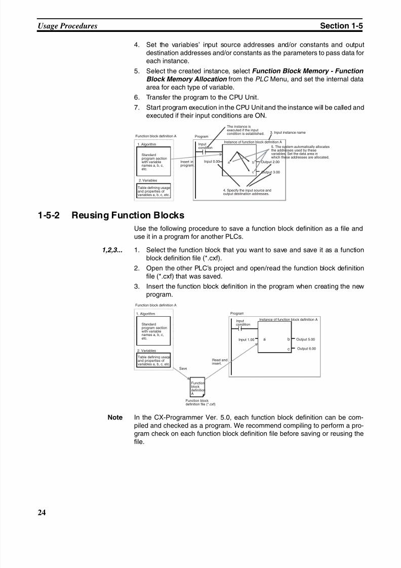
8/11/2019 CX-Programmer V9 Operation Manual FB ST.pdf
http://slidepdf.com/reader/full/cx-programmer-v9-operation-manual-fb-stpdf 50/254
24
Usage Procedures Section 1-5
4. Set the variables’ input source addresses and/or constants and outputdestination addresses and/or constants as the parameters to pass data foreach instance.
5. Select the created instance, select Function Block Memory - Function
Block Memory Allocation from the PLC Menu, and set the internal dataarea for each type of variable.
6. Transfer the program to the CPU Unit.7. Start program execution in the CPU Unit and the instance will be called and
executed if their input conditions are ON.
1-5-2 Reusing Function Blocks
Use the following procedure to save a function block definition as a file anduse it in a program for another PLCs.
1,2,3... 1. Select the function block that you want to save and save it as a functionblock definition file (*.cxf).
2. Open the other PLC’s project and open/read the function block definitionfile (*.cxf) that was saved.
3. Insert the function block definition in the program when creating the newprogram.
Note In the CX-Programmer Ver. 5.0, each function block definition can be com-piled and checked as a program. We recommend compiling to perform a pro-gram check on each function block definition file before saving or reusing thefile.
a b
c
1. Algorithm
2. Variables
Standardprogram sectionwith variablenames a, b, c,etc.
Table defining usageand properties ofvariables a, b, c, etc.
Input 0.00
Function block definition A Program
Insert inprogram.
Inputcondition
The instance isexecuted if the inputcondition is established. 3. Input instance name
Output 2.00
Output 3.00
Instance of function block definition A
5. The system automatically allocatesthe addresses used by thesevariables. Set the data area inwhich these addresses are allocated.
4. Specify the input source andoutput destination addresses.
a b
c
1. Algorithm
2. Variables
Standardprogram sectionwith variablenames a, b, c,etc.
Table defining usageand properties ofvariables a, b, c, etc.
Input 1.00
Function block definition A
Program
Inputcondition
Output 5.00
Output 6.00
Instance of function block definition A
Save
Read andinsert.
FunctionblockdefinitionA
Function blockdefinition file (*.cxf)
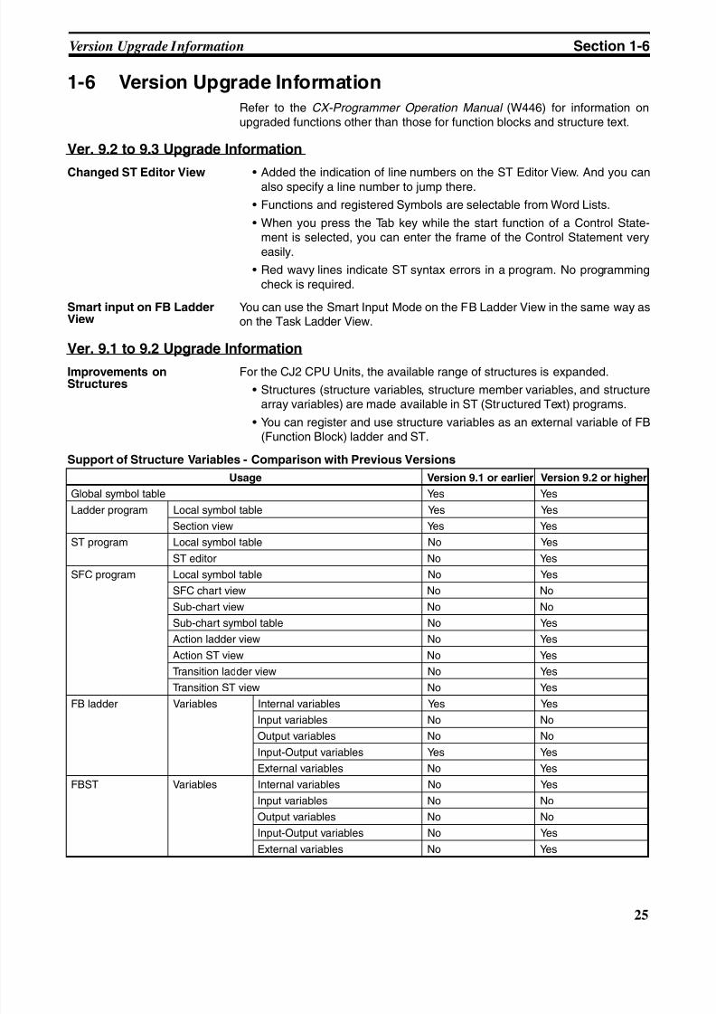
8/11/2019 CX-Programmer V9 Operation Manual FB ST.pdf
http://slidepdf.com/reader/full/cx-programmer-v9-operation-manual-fb-stpdf 51/254
25
Version Upgrade Information Section 1-6
1-6 Version Upgrade Information
Refer to the CX-Programmer Operation Manual (W446) for information onupgraded functions other than those for function blocks and structure text.
Ver. 9.2 to 9.3 Upgrade Information
Changed ST Editor View • Added the indication of line numbers on the ST Editor View. And you canalso specify a line number to jump there.
• Functions and registered Symbols are selectable from Word Lists.
• When you press the Tab key while the start function of a Control State-ment is selected, you can enter the frame of the Control Statement veryeasily.
• Red wavy lines indicate ST syntax errors in a program. No programmingcheck is required.
Smart input on FB LadderView
You can use the Smart Input Mode on the FB Ladder View in the same way ason the Task Ladder View.
Ver. 9.1 to 9.2 Upgrade InformationImprovements onStructures
For the CJ2 CPU Units, the available range of structures is expanded.
• Structures (structure variables, structure member variables, and structurearray variables) are made available in ST (Structured Text) programs.
• You can register and use structure variables as an external variable of FB(Function Block) ladder and ST.
Support of Structure Variables - Comparison with Previous Versions
Usage Version 9.1 or earlier Version 9.2 or higher
Global symbol table Yes Yes
Ladder program Local symbol table Yes Yes
Section view Yes Yes
ST program Local symbol table No Yes
ST editor No Yes
SFC program Local symbol table No Yes
SFC chart view No No
Sub-chart view No No
Sub-chart symbol table No Yes
Action ladder view No Yes
Action ST view No Yes
Transition ladder view No Yes
Transition ST view No Yes
FB ladder Variables Internal variables Yes Yes
Input variables No No
Output variables No No
Input-Output variables Yes Yes
External variables No Yes
FBST Variables Internal variables No Yes
Input variables No No
Output variables No No
Input-Output variables No Yes
External variables No Yes
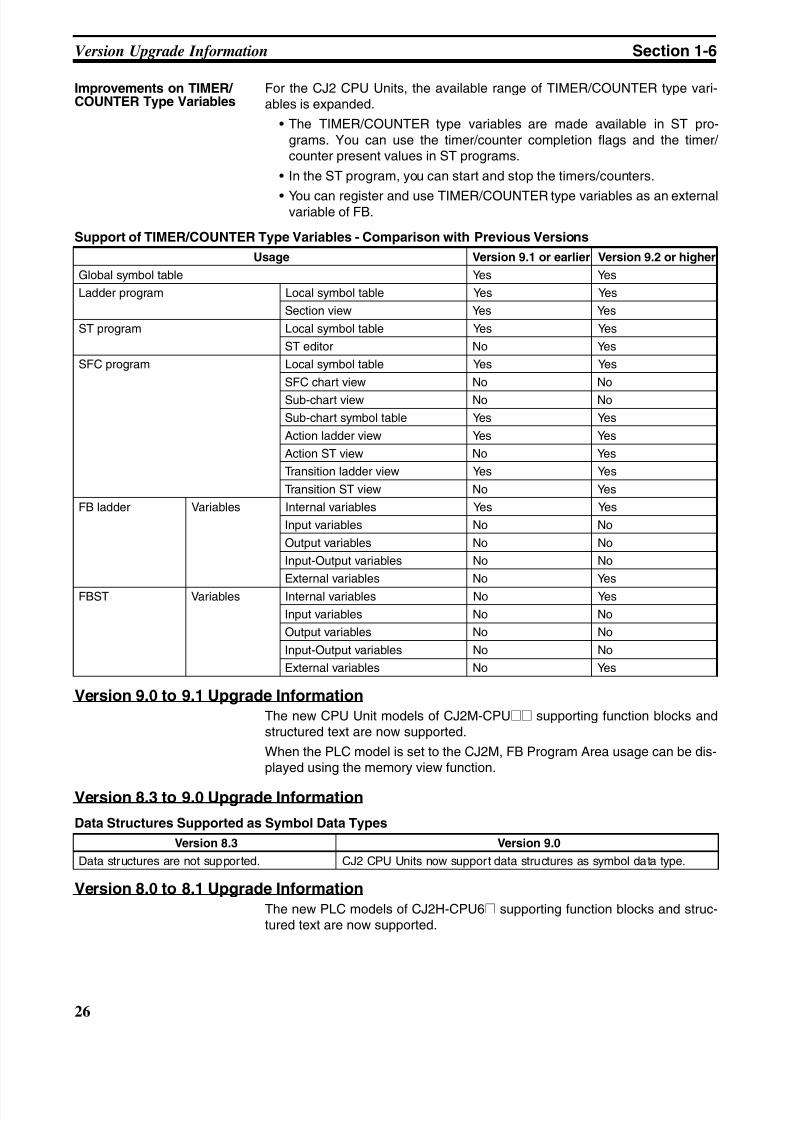
8/11/2019 CX-Programmer V9 Operation Manual FB ST.pdf
http://slidepdf.com/reader/full/cx-programmer-v9-operation-manual-fb-stpdf 52/254
26
Version Upgrade Information Section 1-6
Improvements on TIMER/ COUNTER Type Variables
For the CJ2 CPU Units, the available range of TIMER/COUNTER type vari-ables is expanded.
• The TIMER/COUNTER type variables are made available in ST pro-grams. You can use the timer/counter completion flags and the timer/ counter present values in ST programs.
• In the ST program, you can start and stop the timers/counters.
• You can register and use TIMER/COUNTER type variables as an externalvariable of FB.
Support of TIMER/COUNTER Type Variables - Comparison with Previous Versions
Version 9.0 to 9.1 Upgrade Information
The new CPU Unit models of CJ2M-CPU@@ supporting function blocks andstructured text are now supported.
When the PLC model is set to the CJ2M, FB Program Area usage can be dis-played using the memory view function.
Version 8.3 to 9.0 Upgrade Information
Data Structures Supported as Symbol Data Types
Version 8.0 to 8.1 Upgrade Information
The new PLC models of CJ2H-CPU6@ supporting function blocks and struc-tured text are now supported.
Usage Version 9.1 or earlier Version 9.2 or higher
Global symbol table Yes Yes
Ladder program Local symbol table Yes Yes
Section view Yes Yes
ST program Local symbol table Yes Yes
ST editor No Yes
SFC program Local symbol table Yes Yes
SFC chart view No No
Sub-chart view No No
Sub-chart symbol table Yes Yes
Action ladder view Yes Yes
Action ST view No Yes
Transition ladder view Yes Yes
Transition ST view No Yes
FB ladder Variables Internal variables Yes Yes
Input variables No No
Output variables No No
Input-Output variables No No
External variables No Yes
FBST Variables Internal variables No Yes
Input variables No No
Output variables No No
Input-Output variables No No
External variables No Yes
Version 8.3 Version 9.0
Data structures are not supported. CJ2 CPU Units now support data structures as symbol data type.
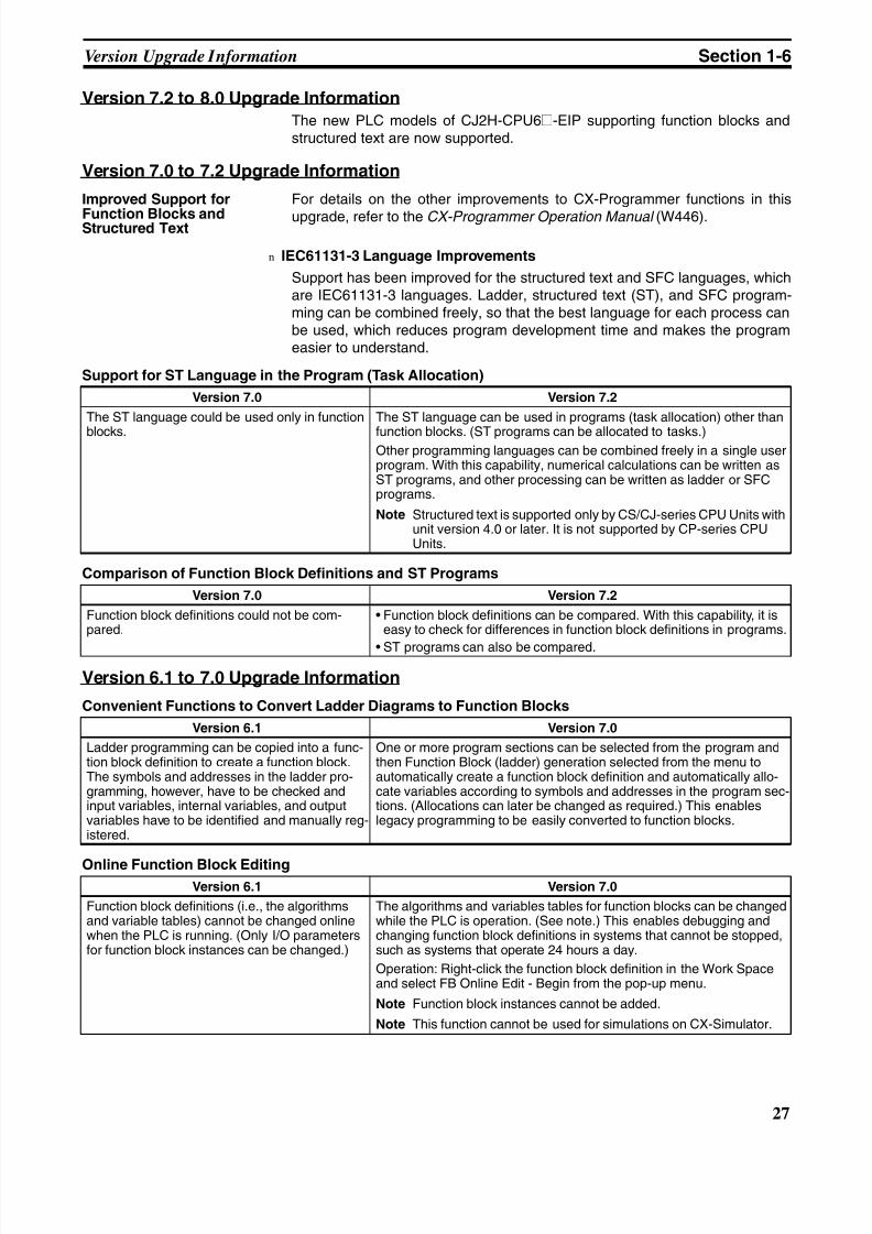
8/11/2019 CX-Programmer V9 Operation Manual FB ST.pdf
http://slidepdf.com/reader/full/cx-programmer-v9-operation-manual-fb-stpdf 53/254
27
Version Upgrade Information Section 1-6
Version 7.2 to 8.0 Upgrade Information
The new PLC models of CJ2H-CPU6@-EIP supporting function blocks andstructured text are now supported.
Version 7.0 to 7.2 Upgrade Information
Improved Support for
Function Blocks andStructured Text
For details on the other improvements to CX-Programmer functions in this
upgrade, refer to the CX-Programmer Operation Manual (W446).
n IEC61131-3 Language Improvements
Support has been improved for the structured text and SFC languages, whichare IEC61131-3 languages. Ladder, structured text (ST), and SFC program-ming can be combined freely, so that the best language for each process canbe used, which reduces program development time and makes the programeasier to understand.
Support for ST Language in the Program (Task Allocation)
Comparison of Function Block Definitions and ST Programs
Version 6.1 to 7.0 Upgrade Information
Convenient Functions to Convert Ladder Diagrams to Function Blocks
Online Function Block Editing
Version 7.0 Version 7.2
The ST language could be used only in function
blocks.
The ST language can be used in programs (task allocation) other than
function blocks. (ST programs can be allocated to tasks.)Other programming languages can be combined freely in a single userprogram. With this capability, numerical calculations can be written asST programs, and other processing can be written as ladder or SFCprograms.
Note Structured text is supported only by CS/CJ-series CPU Units withunit version 4.0 or later. It is not supported by CP-series CPUUnits.
Version 7.0 Version 7.2
Function block definitions could not be com-pared.
• Function block definitions can be compared. With this capability, it iseasy to check for differences in function block definitions in programs.
• ST programs can also be compared.
Version 6.1 Version 7.0
Ladder programming can be copied into a func-tion block definition to create a function block.The symbols and addresses in the ladder pro-gramming, however, have to be checked andinput variables, internal variables, and outputvariables have to be identified and manually reg-istered.
One or more program sections can be selected from the program andthen Function Block (ladder) generation selected from the menu toautomatically create a function block definition and automatically allo-cate variables according to symbols and addresses in the program sec-tions. (Allocations can later be changed as required.) This enableslegacy programming to be easily converted to function blocks.
Version 6.1 Version 7.0
Function block definitions (i.e., the algorithmsand variable tables) cannot be changed onlinewhen the PLC is running. (Only I/O parametersfor function block instances can be changed.)
The algorithms and variables tables for function blocks can be changedwhile the PLC is operation. (See note.) This enables debugging andchanging function block definitions in systems that cannot be stopped,such as systems that operate 24 hours a day.
Operation: Right-click the function block definition in the Work Spaceand select FB Online Edit - Begin from the pop-up menu.
Note Function block instances cannot be added.
Note This function cannot be used for simulations on CX-Simulator.
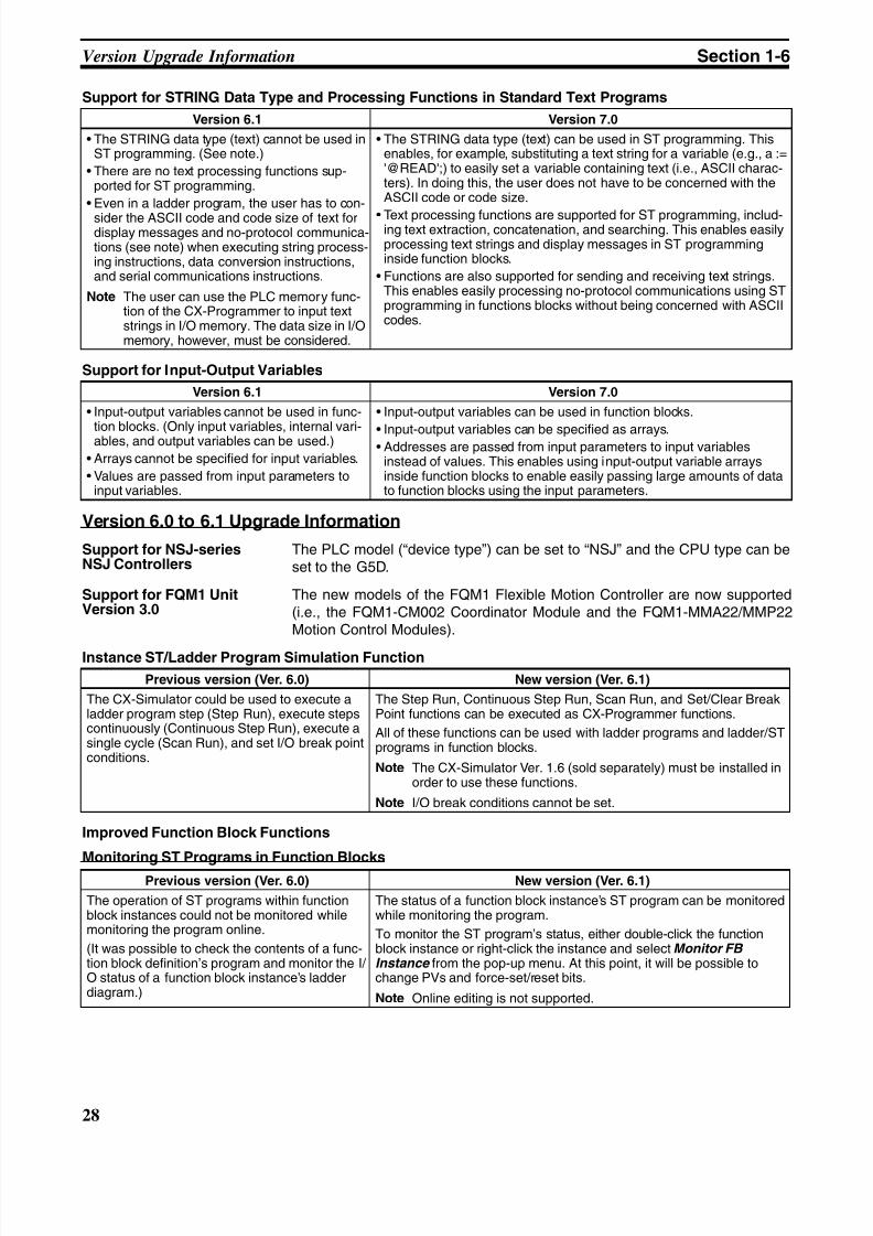
8/11/2019 CX-Programmer V9 Operation Manual FB ST.pdf
http://slidepdf.com/reader/full/cx-programmer-v9-operation-manual-fb-stpdf 54/254
28
Version Upgrade Information Section 1-6
Support for STRING Data Type and Processing Functions in Standard Text Programs
Support for Input-Output Variables
Version 6.0 to 6.1 Upgrade Information
Support for NSJ-seriesNSJ Controllers
The PLC model (“device type”) can be set to “NSJ” and the CPU type can beset to the G5D.
Support for FQM1 UnitVersion 3.0
The new models of the FQM1 Flexible Motion Controller are now supported(i.e., the FQM1-CM002 Coordinator Module and the FQM1-MMA22/MMP22Motion Control Modules).
Instance ST/Ladder Program Simulation Function
Improved Function Block Functions
Monitoring ST Programs in Function Blocks
Version 6.1 Version 7.0
• The STRING data type (text) cannot be used inST programming. (See note.)
• There are no text processing functions sup-ported for ST programming.
• Even in a ladder program, the user has to con-
sider the ASCII code and code size of text fordisplay messages and no-protocol communica-tions (see note) when executing string process-ing instructions, data conversion instructions,and serial communications instructions.
Note The user can use the PLC memory func-tion of the CX-Programmer to input textstrings in I/O memory. The data size in I/Omemory, however, must be considered.
• The STRING data type (text) can be used in ST programming. Thisenables, for example, substituting a text string for a variable (e.g., a :='@READ';) to easily set a variable containing text (i.e., ASCII charac-ters). In doing this, the user does not have to be concerned with theASCII code or code size.
• Text processing functions are supported for ST programming, includ-ing text extraction, concatenation, and searching. This enables easilyprocessing text strings and display messages in ST programminginside function blocks.
• Functions are also supported for sending and receiving text strings.This enables easily processing no-protocol communications using STprogramming in functions blocks without being concerned with ASCIIcodes.
Version 6.1 Version 7.0
• Input-output variables cannot be used in func-
tion blocks. (Only input variables, internal vari-ables, and output variables can be used.)
• Arrays cannot be specified for input variables.
• Values are passed from input parameters toinput variables.
• Input-output variables can be used in function blocks.
• Input-output variables can be specified as arrays.• Addresses are passed from input parameters to input variables
instead of values. This enables using input-output variable arraysinside function blocks to enable easily passing large amounts of datato function blocks using the input parameters.
Previous version (Ver. 6.0) New version (Ver. 6.1)
The CX-Simulator could be used to execute aladder program step (Step Run), execute stepscontinuously (Continuous Step Run), execute asingle cycle (Scan Run), and set I/O break pointconditions.
The Step Run, Continuous Step Run, Scan Run, and Set/Clear BreakPoint functions can be executed as CX-Programmer functions.
All of these functions can be used with ladder programs and ladder/STprograms in function blocks.
Note The CX-Simulator Ver. 1.6 (sold separately) must be installed inorder to use these functions.
Note I/O break conditions cannot be set.
Previous version (Ver. 6.0) New version (Ver. 6.1)
The operation of ST programs within functionblock instances could not be monitored whilemonitoring the program online.
(It was possible to check the contents of a func-tion block definition’s program and monitor the I/ O status of a function block instance’s ladderdiagram.)
The status of a function block instance’s ST program can be monitoredwhile monitoring the program.
To monitor the ST program’s status, either double-click the functionblock instance or right-click the instance and select Monitor FBInstance from the pop-up menu. At this point, it will be possible tochange PVs and force-set/reset bits.
Note Online editing is not supported.
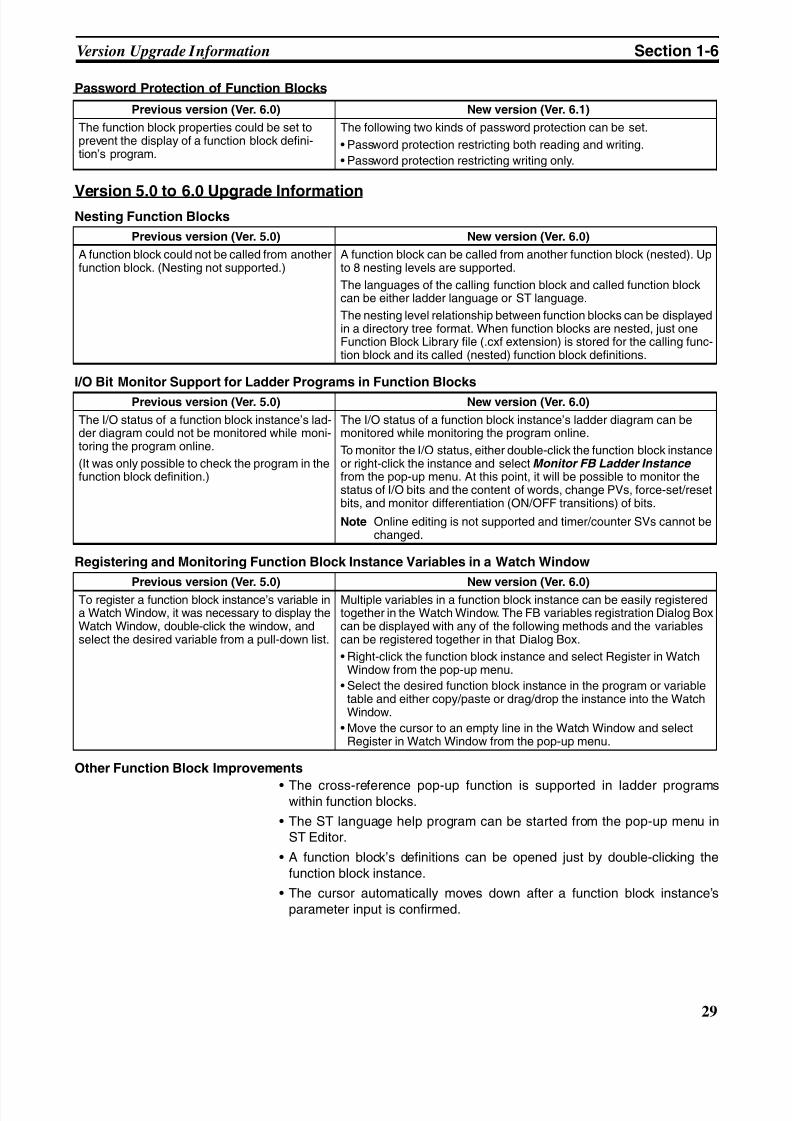
8/11/2019 CX-Programmer V9 Operation Manual FB ST.pdf
http://slidepdf.com/reader/full/cx-programmer-v9-operation-manual-fb-stpdf 55/254
29
Version Upgrade Information Section 1-6
Password Protection of Function Blocks
Version 5.0 to 6.0 Upgrade InformationNesting Function Blocks
I/O Bit Monitor Support for Ladder Programs in Function Blocks
Registering and Monitoring Function Block Instance Variables in a Watch Window
Other Function Block Improvements
• The cross-reference pop-up function is supported in ladder programswithin function blocks.
• The ST language help program can be started from the pop-up menu inST Editor.
• A function block’s definitions can be opened just by double-clicking thefunction block instance.
• The cursor automatically moves down after a function block instance’sparameter input is confirmed.
Previous version (Ver. 6.0) New version (Ver. 6.1)
The function block properties could be set toprevent the display of a function block defini-tion’s program.
The following two kinds of password protection can be set.
• Password protection restricting both reading and writing.
• Password protection restricting writing only.
Previous version (Ver. 5.0) New version (Ver. 6.0)
A function block could not be called from anotherfunction block. (Nesting not supported.)
A function block can be called from another function block (nested). Upto 8 nesting levels are supported.
The languages of the calling function block and called function blockcan be either ladder language or ST language.
The nesting level relationship between function blocks can be displayedin a directory tree format. When function blocks are nested, just oneFunction Block Library file (.cxf extension) is stored for the calling func-tion block and its called (nested) function block definitions.
Previous version (Ver. 5.0) New version (Ver. 6.0)
The I/O status of a function block instance’s lad-der diagram could not be monitored while moni-toring the program online.
(It was only possible to check the program in thefunction block definition.)
The I/O status of a function block instance’s ladder diagram can bemonitored while monitoring the program online.
To monitor the I/O status, either double-click the function block instanceor right-click the instance and select Monitor FB Ladder Instance from the pop-up menu. At this point, it will be possible to monitor thestatus of I/O bits and the content of words, change PVs, force-set/resetbits, and monitor differentiation (ON/OFF transitions) of bits.
Note Online editing is not supported and timer/counter SVs cannot bechanged.
Previous version (Ver. 5.0) New version (Ver. 6.0)
To register a function block instance’s variable ina Watch Window, it was necessary to display theWatch Window, double-click the window, andselect the desired variable from a pull-down list.
Multiple variables in a function block instance can be easily registeredtogether in the Watch Window. The FB variables registration Dialog Boxcan be displayed with any of the following methods and the variablescan be registered together in that Dialog Box.
• Right-click the function block instance and select Register in WatchWindow from the pop-up menu.
• Select the desired function block instance in the program or variabletable and either copy/paste or drag/drop the instance into the WatchWindow.
• Move the cursor to an empty line in the Watch Window and selectRegister in Watch Window from the pop-up menu.

8/11/2019 CX-Programmer V9 Operation Manual FB ST.pdf
http://slidepdf.com/reader/full/cx-programmer-v9-operation-manual-fb-stpdf 56/254
30
Version Upgrade Information Section 1-6
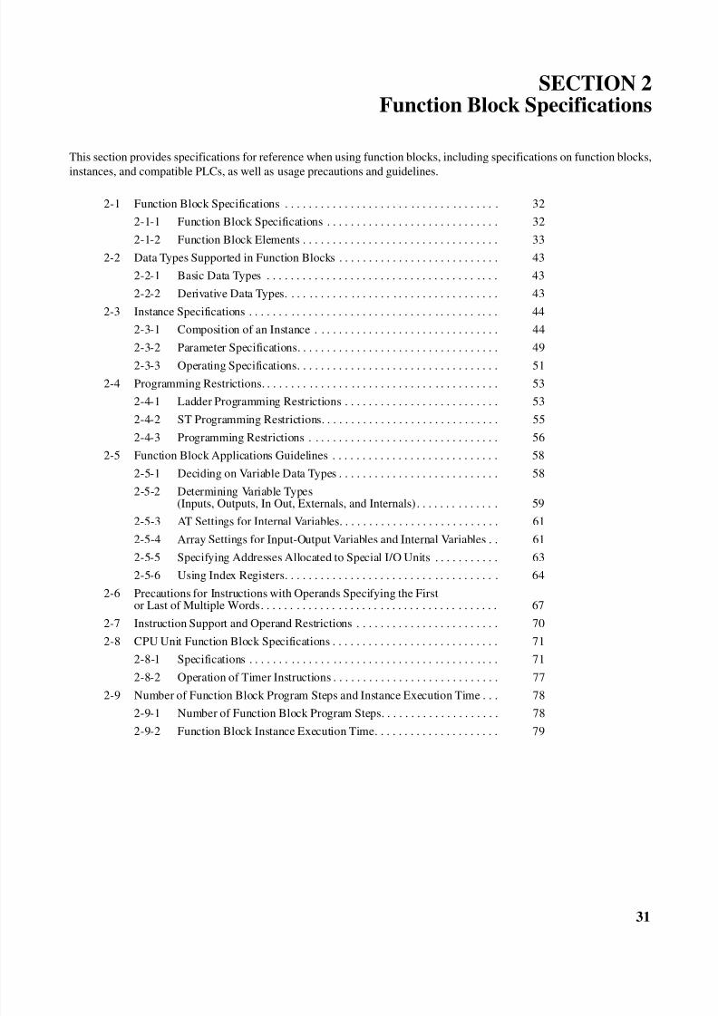
8/11/2019 CX-Programmer V9 Operation Manual FB ST.pdf
http://slidepdf.com/reader/full/cx-programmer-v9-operation-manual-fb-stpdf 57/254
31
SECTION 2Function Block Specifications
This section provides specifications for reference when using function blocks, including specifications on function blocks,
instances, and compatible PLCs, as well as usage precautions and guidelines.
2-1 Function Block Specifications . . . . . . . . . . . . . . . . . . . . . . . . . . . . . . . . . . . . 32
2-1-1 Function Block Specifications . . . . . . . . . . . . . . . . . . . . . . . . . . . . . 32
2-1-2 Function Block Elements . . . . . . . . . . . . . . . . . . . . . . . . . . . . . . . . . 33
2-2 Data Types Supported in Function Blocks . . . . . . . . . . . . . . . . . . . . . . . . . . . 43
2-2-1 Basic Data Types . . . . . . . . . . . . . . . . . . . . . . . . . . . . . . . . . . . . . . . 43
2-2-2 Derivative Data Types. . . . . . . . . . . . . . . . . . . . . . . . . . . . . . . . . . . . 43
2-3 Instance Specifications . . . . . . . . . . . . . . . . . . . . . . . . . . . . . . . . . . . . . . . . . . 44
2-3-1 Composition of an Instance . . . . . . . . . . . . . . . . . . . . . . . . . . . . . . . 44
2-3-2 Parameter Specifications. . . . . . . . . . . . . . . . . . . . . . . . . . . . . . . . . . 49
2-3-3 Operating Specifications. . . . . . . . . . . . . . . . . . . . . . . . . . . . . . . . . . 51
2-4 Programming Restrictions. . . . . . . . . . . . . . . . . . . . . . . . . . . . . . . . . . . . . . . . 53
2-4-1 Ladder Programming Restrictions . . . . . . . . . . . . . . . . . . . . . . . . . . 53
2-4-2 ST Programming Restrictions. . . . . . . . . . . . . . . . . . . . . . . . . . . . . . 55
2-4-3 Programming Restrictions . . . . . . . . . . . . . . . . . . . . . . . . . . . . . . . . 56
2-5 Function Block Applications Guidelines . . . . . . . . . . . . . . . . . . . . . . . . . . . . 58
2-5-1 Deciding on Variable Data Types . . . . . . . . . . . . . . . . . . . . . . . . . . . 58
2-5-2 Determining Variable Types(Inputs, Outputs, In Out, Externals, and Internals). . . . . . . . . . . . . . 59
2-5-3 AT Settings for Internal Variables. . . . . . . . . . . . . . . . . . . . . . . . . . . 61
2-5-4 Array Settings for Input-Output Variables and Internal Variables . . 61
2-5-5 Specifying Addresses Allocated to Special I/O Units . . . . . . . . . . . 63
2-5-6 Using Index Registers. . . . . . . . . . . . . . . . . . . . . . . . . . . . . . . . . . . . 64
2-6 Precautions for Instructions with Operands Specifying the Firstor Last of Multiple Words. . . . . . . . . . . . . . . . . . . . . . . . . . . . . . . . . . . . . . . . 67
2-7 Instruction Support and Operand Restrictions . . . . . . . . . . . . . . . . . . . . . . . . 70
2-8 CPU Unit Function Block Specifications . . . . . . . . . . . . . . . . . . . . . . . . . . . . 71
2-8-1 Specifications . . . . . . . . . . . . . . . . . . . . . . . . . . . . . . . . . . . . . . . . . . 71
2-8-2 Operation of Timer Instructions . . . . . . . . . . . . . . . . . . . . . . . . . . . . 77
2-9 Number of Function Block Program Steps and Instance Execution Time . . . 78
2-9-1 Number of Function Block Program Steps. . . . . . . . . . . . . . . . . . . . 78
2-9-2 Function Block Instance Execution Time. . . . . . . . . . . . . . . . . . . . . 79
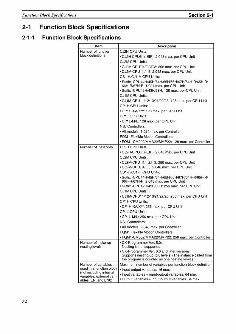
8/11/2019 CX-Programmer V9 Operation Manual FB ST.pdf
http://slidepdf.com/reader/full/cx-programmer-v9-operation-manual-fb-stpdf 58/254
32
Function Block Specifications Section 2-1
2-1 Function Block Specifications
2-1-1 Function Block Specifications
Item Description
Number of functionblock definitions
CJ2H CPU Units:
• CJ2H-CPU6@(-EIP): 2,048 max. per CPU UnitCJ2M CPU Units:
• CJ2M-CPU@1/ @2/ @3: 256 max. per CPU Unit
• CJ2M-CPU@4/ @5: 2,048 max. per CPU Unit
CS1-H/CJ1-H CPU Units:
• Suffix -CPU44H/45H/64H/65H/66H/67H/64H-R/65H-R/ 66H-R/67H-R: 1,024 max. per CPU Unit
• Suffix -CPU42H/43H/63H: 128 max. per CPU Unit
CJ1M CPU Units:
• CJ1M-CPU11/12/13/21/22/23: 128 max. per CPU Unit
CP1H CPU Units:
• CP1H-XA/X/Y: 128 max. per CPU Unit
CP1L CPU Units:• CP1L-M/L: 128 max. per CPU Unit
NSJ Controllers:
• All models: 1,024 max. per Controller
FQM1 Flexible Motion Controllers:
• FQM1-CM002/MMA22/MMP22: 128 max. per Controller
Number of instances CJ2H CPU Units:
• CJ2H-CPU6@(-EIP): 2,048 max. per CPU Unit
CJ2M CPU Units:
• CJ2M-CPU@1/ @2/ @3: 256 max. per CPU Unit
• CJ2M-CPU@4/ @5: 2,048 max. per CPU Unit
CS1-H/CJ1-H CPU Units:
• Suffix -CPU44H/45H/64H/65H/66H/67H/64H-R/65H-R/ 66H-R/67H-R: 2,048 max. per CPU Unit
• Suffix -CPU42H/43H/63H: 256 max. per CPU Unit
CJ1M CPU Units:
• CJ1M-CPU11/12/13/21/22/23: 256 max. per CPU Unit
CP1H CPU Units:
• CP1H-XA/X/Y: 256 max. per CPU Unit
CP1L CPU Units:
• CP1L-M/L: 256 max. per CPU Unit
NSJ Controllers:
• All models: 2,048 max. per Controller
FQM1 Flexible Motion Controllers:• FQM1-CM002/MMA22/MMP22: 256 max. per Controller
Number of instancenesting levels
• CX-Programmer Ver. 5.0:Nesting is not supported.
• CX-Programmer Ver. 6.0 and later versions:Supports nesting up to 8 levels. (The instance called fromthe program is counted as one nesting level.)
Number of variablesused in a function block(not including internalvariables, external vari-ables, EN, and EN0)
Maximum number of variables per function block definition
• Input-output variables: 16 max.
• Input variables + input-output variables: 64 max.
• Output variables + input-output variables: 64 max.
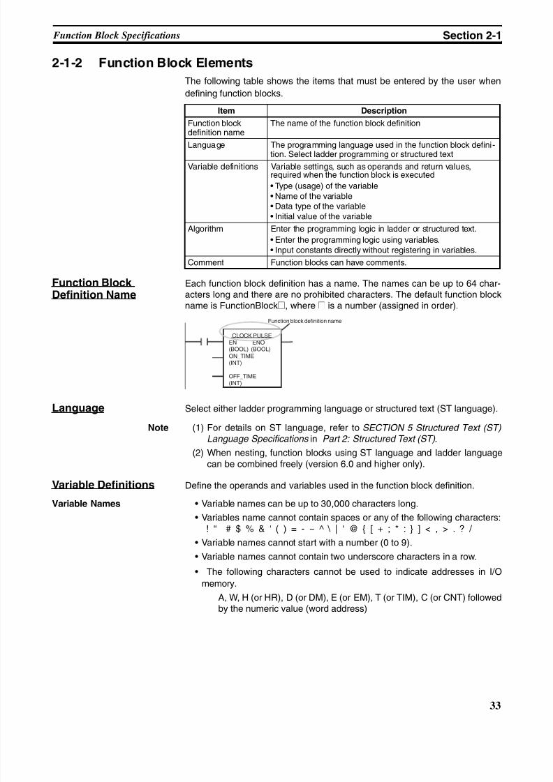
8/11/2019 CX-Programmer V9 Operation Manual FB ST.pdf
http://slidepdf.com/reader/full/cx-programmer-v9-operation-manual-fb-stpdf 59/254
33
Function Block Specifications Section 2-1
2-1-2 Function Block Elements
The following table shows the items that must be entered by the user when
defining function blocks.
Function BlockDefinition Name
Each function block definition has a name. The names can be up to 64 char-acters long and there are no prohibited characters. The default function blockname is FunctionBlock@, where @ is a number (assigned in order).
Language Select either ladder programming language or structured text (ST language).
Note (1) For details on ST language, refer to SECTION 5 Structured Text (ST) Language Specifications in Part 2: Structured Text (ST) .
(2) When nesting, function blocks using ST language and ladder languagecan be combined freely (version 6.0 and higher only).
Variable Definitions Define the operands and variables used in the function block definition.
Variable Names • Variable names can be up to 30,000 characters long.
• Variables name cannot contain spaces or any of the following characters:! “ # $ % & ‘ ( ) = - ~ ^ \ | ‘ @ { [ + ; * : } ] < , > . ? /
• Variable names cannot start with a number (0 to 9).
• Variable names cannot contain two underscore characters in a row.
• The following characters cannot be used to indicate addresses in I/O
memory.
A, W, H (or HR), D (or DM), E (or EM), T (or TIM), C (or CNT) followedby the numeric value (word address)
Item Description
Function block
definition name
The name of the function block definition
Language The programming language used in the function block defini-tion. Select ladder programming or structured text
Variable definitions Variable settings, such as operands and return values,required when the function block is executed
• Type (usage) of the variable• Name of the variable• Data type of the variable• Initial value of the variable
Algorithm Enter the programming logic in ladder or structured text.
• Enter the programming logic using variables.• Input constants directly without registering in variables.
Comment Function blocks can have comments.
CLOCK PULSEEN ENO(BOOL) (BOOL)ON_TIME(INT)
OFF_TIME(INT)
Function block definition name
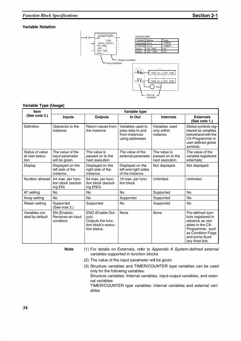
8/11/2019 CX-Programmer V9 Operation Manual FB ST.pdf
http://slidepdf.com/reader/full/cx-programmer-v9-operation-manual-fb-stpdf 60/254
34
Function Block Specifications Section 2-1
Variable Notation
Variable Type (Usage)
Note (1) For details on Externals, refer to Appendix A System-defined external variables supported in function blocks .
(2) The value of the input parameter will be given.
(3) Structure variables and TIMER/COUNTER type variables can be usedonly for the following variables:Structure variables: Internal variables, input-output variables, and exter-nal variablesTIMER/COUNTER type variables: Internal variables and external vari-ables
CLOCK PULSE
EN ENO
(BOOL) (BOOL)ON_TIME (INT)OFF_TIME(INT)
TIMX tim_a OFF_TIMEtim_b
TIMX tim_b OFF_TIMEtim_a
ENO
tim_a TIMERtim_b TIMERON_TIME INT
OFF_TIME INT
Input variablesOutput variables
Internalvariables
Variable table
NameInternalInternalInputInput
TypeUsage
Item(See note 3.)
Variable type
Inputs Outputs In Out Internals Externals(See note 1.)
Definition Operands to theinstance
Return values fromthe instance
Variables used topass data to andfrom instancesusing addresses
Variables usedonly withininstance
Global symbols reg-istered as variablesbeforehand with theCX-Programmer oruser-defined globalsymbols.
Status of valueat next execu-tion
The value of theinput parameterwill be given.
The value ispassed on to thenext execution.
The value of theexternal parameter
The value ispassed on to thenext execution.
The value of thevariable registeredexternally
Display Displayed on theleft side of theinstance.
Displayed on theright side of theinstance.
Displayed on theleft and right sidesof the instance.
Not displayed. Not displayed.
Number allowed 64 max. per func-tion block (exclud-ing EN)
64 max. per func-tion block (exclud-ing ENO)
16 max. per func-tion block
Unlimited Unlimited
AT setting No No No Supported No
Array setting No No Supported Supported No
Retain setting Supported(See note 2.)
Supported No Supported No
Variables cre-ated by default
EN (Enable):Receives an inputcondition.
ENO (Enable Out-put):Outputs the func-tion block’s execu-tion status.
None None Pre-defined sym-bols registered inadvance as vari-ables in the CX-Programmer, suchas Condition Flagsand some Auxil-iary Area bits.
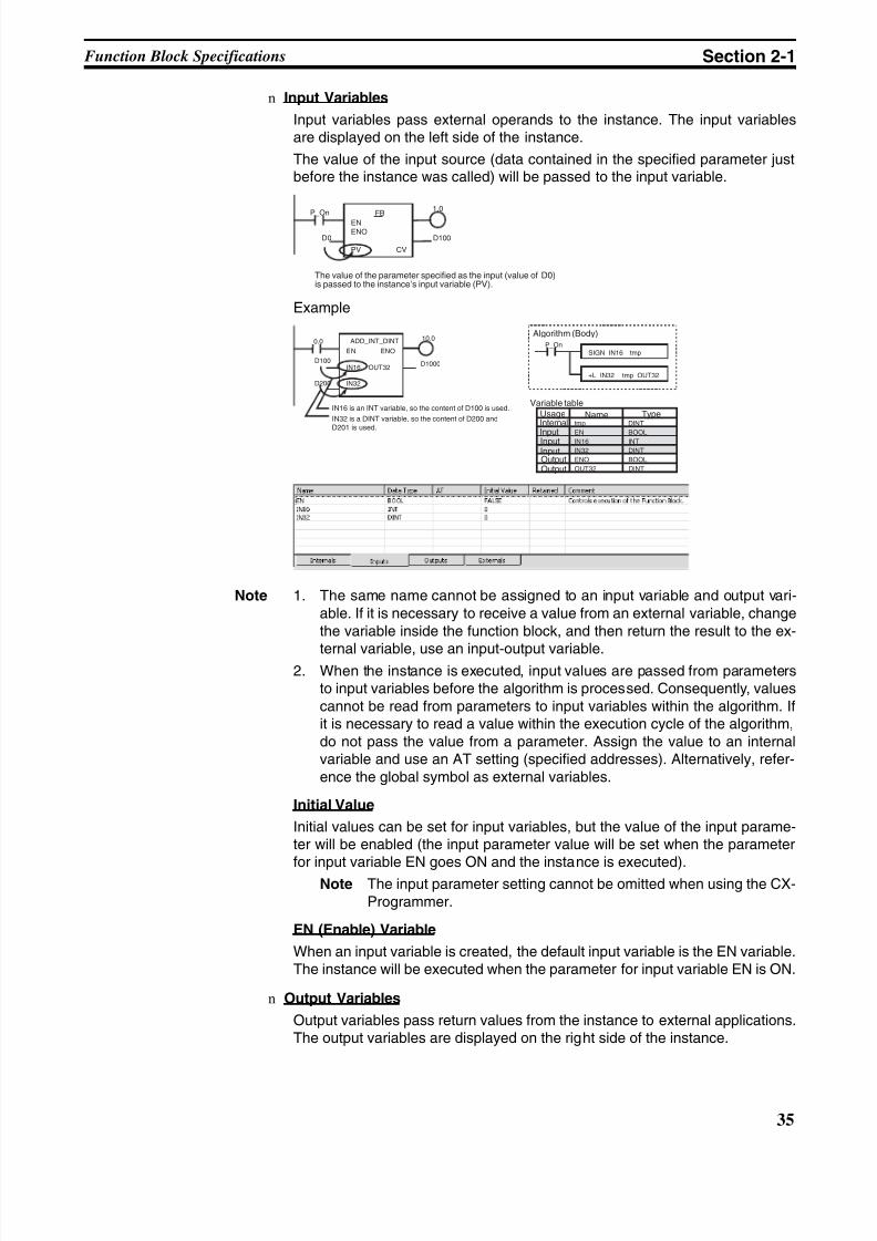
8/11/2019 CX-Programmer V9 Operation Manual FB ST.pdf
http://slidepdf.com/reader/full/cx-programmer-v9-operation-manual-fb-stpdf 61/254
35
Function Block Specifications Section 2-1
n Input Variables
Input variables pass external operands to the instance. The input variablesare displayed on the left side of the instance.
The value of the input source (data contained in the specified parameter justbefore the instance was called) will be passed to the input variable.
Example
Note 1. The same name cannot be assigned to an input variable and output vari-able. If it is necessary to receive a value from an external variable, changethe variable inside the function block, and then return the result to the ex-
ternal variable, use an input-output variable.2. When the instance is executed, input values are passed from parameters
to input variables before the algorithm is processed. Consequently, valuescannot be read from parameters to input variables within the algorithm. Ifit is necessary to read a value within the execution cycle of the algorithm,do not pass the value from a parameter. Assign the value to an internalvariable and use an AT setting (specified addresses). Alternatively, refer-ence the global symbol as external variables.
Initial Value
Initial values can be set for input variables, but the value of the input parame-ter will be enabled (the input parameter value will be set when the parameter
for input variable EN goes ON and the instance is executed).Note The input parameter setting cannot be omitted when using the CX-
Programmer.
EN (Enable) Variable
When an input variable is created, the default input variable is the EN variable.The instance will be executed when the parameter for input variable EN is ON.
n Output Variables
Output variables pass return values from the instance to external applications.The output variables are displayed on the right side of the instance.
P_On1.0
FB
ENENO
PV CV
D0 D100
The value of the parameter specified as the input (value of D0)is passed to the instance’s input variable (PV).
D1000
0.0 10.0
D200
ADD_INT_DINT
EN ENO
IN16 OUT32
IN32
D100
tmp DINT
EN BOOLIN16 INT
IN32 DINT
ENO BOOL
OUT32 DINT
SIGN IN16 tmpP_On
+L IN32 tmp OUT32
IN16 is an INT variable, so the content of D100 is used.
IN32 is a DINT variable, so the content of D200 andD201 is used.
Algorithm (Body)
Variable table
NameInternal
InputInputInputOutputOutput
TypeUsage
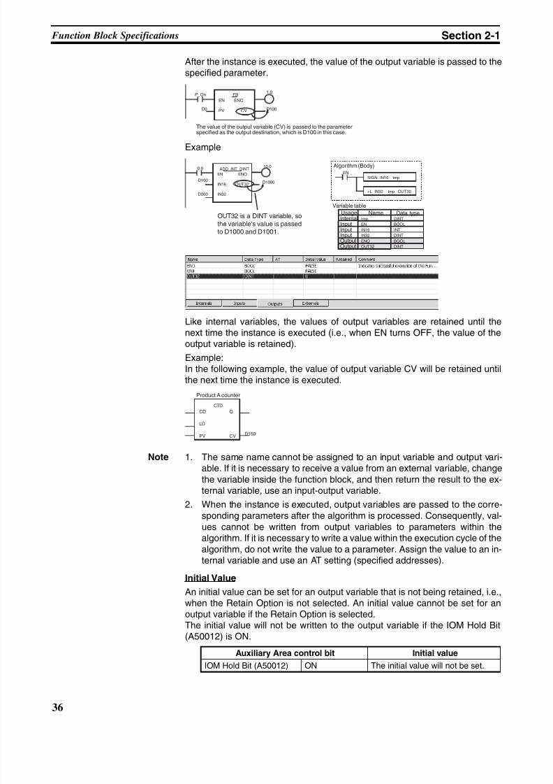
8/11/2019 CX-Programmer V9 Operation Manual FB ST.pdf
http://slidepdf.com/reader/full/cx-programmer-v9-operation-manual-fb-stpdf 62/254
36
Function Block Specifications Section 2-1
After the instance is executed, the value of the output variable is passed to thespecified parameter.
Example
Like internal variables, the values of output variables are retained until thenext time the instance is executed (i.e., when EN turns OFF, the value of theoutput variable is retained).
Example:In the following example, the value of output variable CV will be retained untilthe next time the instance is executed.
Note 1. The same name cannot be assigned to an input variable and output vari-able. If it is necessary to receive a value from an external variable, changethe variable inside the function block, and then return the result to the ex-ternal variable, use an input-output variable.
2. When the instance is executed, output variables are passed to the corre-sponding parameters after the algorithm is processed. Consequently, val-ues cannot be written from output variables to parameters within thealgorithm. If it is necessary to write a value within the execution cycle of the
algorithm, do not write the value to a parameter. Assign the value to an in-ternal variable and use an AT setting (specified addresses).
Initial Value
An initial value can be set for an output variable that is not being retained, i.e.,when the Retain Option is not selected. An initial value cannot be set for anoutput variable if the Retain Option is selected.The initial value will not be written to the output variable if the IOM Hold Bit(A50012) is ON.
P_On FB
EN ENO
PV CVD0 D100
1.0
The value of the output variable (CV) is passed to the parameterspecified as the output destination, which is D100 in this case.
D1000
0.0 10.0
D200
ADD_INT_DINT
EN ENO
IN16 OUT32
IN32
D100
tmp DINT
EN BOOL
IN16 INT
IN32 DINT
ENO BOOL
OUT32 DINT
SIGN IN16 tmpEN
+L IN32 tmp OUT32
OUT32 is a DINT variable, sothe variable's value is passedto D1000 and D1001.
Algorithm (Body)
Variable table
NameInternalInputInputInputOutputOutput
Data typeUsage
CTD
CD Q
LD
PV CV D150
Product A counter
Auxiliary Area control bit Initial value
IOM Hold Bit (A50012) ON The initial value will not be set.
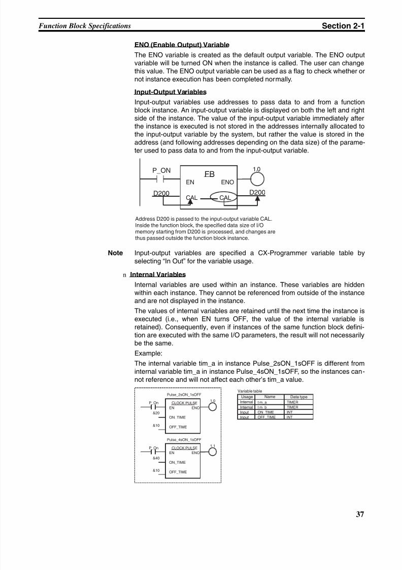
8/11/2019 CX-Programmer V9 Operation Manual FB ST.pdf
http://slidepdf.com/reader/full/cx-programmer-v9-operation-manual-fb-stpdf 63/254
37
Function Block Specifications Section 2-1
ENO (Enable Output) Variable
The ENO variable is created as the default output variable. The ENO outputvariable will be turned ON when the instance is called. The user can changethis value. The ENO output variable can be used as a flag to check whether ornot instance execution has been completed normally.
Input-Output Variables
Input-output variables use addresses to pass data to and from a functionblock instance. An input-output variable is displayed on both the left and rightside of the instance. The value of the input-output variable immediately afterthe instance is executed is not stored in the addresses internally allocated tothe input-output variable by the system, but rather the value is stored in theaddress (and following addresses depending on the data size) of the parame-ter used to pass data to and from the input-output variable.
Note Input-output variables are specified a CX-Programmer variable table byselecting “In Out” for the variable usage.
n Internal Variables
Internal variables are used within an instance. These variables are hiddenwithin each instance. They cannot be referenced from outside of the instance
and are not displayed in the instance.The values of internal variables are retained until the next time the instance isexecuted (i.e., when EN turns OFF, the value of the internal variable isretained). Consequently, even if instances of the same function block defini-tion are executed with the same I/O parameters, the result will not necessarilybe the same.
Example:
The internal variable tim_a in instance Pulse_2sON_1sOFF is different frominternal variable tim_a in instance Pulse_4sON_1sOFF, so the instances can-not reference and will not affect each other’s tim_a value.
1.0FB
EN ENO
CAL CAL
P_ON
D200 D200
Address D200 is passed to the input-output variable CAL.Inside the function block, the specified data size of I/Omemory starting from D200 is processed, and changes arethus passed outside the function block instance.
P_On 1.0
&10
CLOCK PULSE
EN ENO
ON_TIME
OFF_TIME
&20
Pulse_2sON_1sOFF
P_On1.1
&10
CLOCK PULSE
EN ENO
ON_TIME
OFF_TIME
&40
Pulse_4sON_1sOFF
tim_a TIMER
tim_b TIMER
ON_TIME INT
OFF_TIME INT
Variable table
Name
Internal
InternalInputInput
Data typeUsage
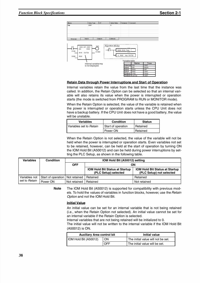
8/11/2019 CX-Programmer V9 Operation Manual FB ST.pdf
http://slidepdf.com/reader/full/cx-programmer-v9-operation-manual-fb-stpdf 64/254
38
Function Block Specifications Section 2-1
Retain Data through Power Interruptions and Start of Operation
Internal variables retain the value from the last time that the instance wascalled. In addition, the Retain Option can be selected so that an internal vari-able will also retains its value when the power is interrupted or operation
starts (the mode is switched from PROGRAM to RUN or MONITOR mode).When the Retain Option is selected, the value of the variable is retained whenthe power is interrupted or operation starts unless the CPU Unit does nothave a backup battery. If the CPU Unit does not have a good battery, the valuewill be unstable.
When the Retain Option is not selected, the value of the variable will not beheld when the power is interrupted or operation starts. Even variables not setto be retained, however, can be held at the start of operation by turning ONthe IOM Hold Bit (A50012) and can be held during power interruptions by set-ting the PLC Setup, as shown in the following table.
Note The IOM Hold Bit (A50012) is supported for compatibility with previous mod-els. To hold the values of variables in function blocks, however, use the Retain
Option and not the IOM Hold Bit.Initial Value
An initial value can be set for an internal variable that is not being retained(i.e., when the Retain Option not selected). An initial value cannot be set foran internal variable if the Retain Option is selected.Internal variables that are not being retained will be initialized to 0.The initial value will not be written to the internal variable if the IOM Hold Bit
(A50012) is ON.
Variables Condition Status
Variables set to Retain Start of operation Retained
Power ON Retained
SIGN IN16 tmpEN
+L IN32 tmp OUT32
tmp DINT
EN BOOL
IN16 INT
IN32 DINT
ENO BOOL
OUT32 DINT
D1000
0.0 10.0
D200
ADD_INT_DINT
EN ENO
IN16 OUT32
IN32
D100
Internal variable tmpis not displayed.
Algorithm (Body)
Variable tableName
InternalInputInputInputOutputOutput
Type
Variables Condition IOM Hold Bit (A50012) setting
OFF ON
IOM Hold Bit Status at Startup(PLC Setup) selected
IOM Hold Bit Status at Startup(PLC Setup) not selected
Variables notset to Retain
Start of operation Not retained Retained Retained
Power ON Not retained Retained Not retained
Auxiliary Area control bit Initial value
IOM Hold Bit (A50012) ON The initial value will not be set.
OFF The initial value will be set.
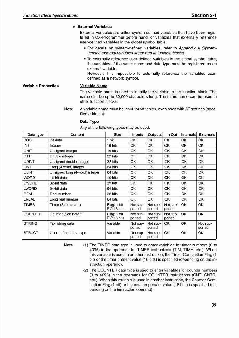
8/11/2019 CX-Programmer V9 Operation Manual FB ST.pdf
http://slidepdf.com/reader/full/cx-programmer-v9-operation-manual-fb-stpdf 65/254
39
Function Block Specifications Section 2-1
n External Variables
External variables are either system-defined variables that have been regis-tered in CX-Programmer before hand, or variables that externally referenceuser-defined variables in the global symbol table.
• For details on system-defined variables, refer to Appendix A System-
defined external variables supported in function blocks .
• To externally reference user-defined variables in the global symbol table,the variables of the same name and data type must be registered as anexternal variable.However, it is impossible to externally reference the variables user-defined as a network symbol.
Variable Properties Variable Name
The variable name is used to identify the variable in the function block. Thename can be up to 30,000 characters long. The same name can be used inother function blocks.
Note A variable name must be input for variables, even ones with AT settings (spec-ified address).
Data Type
Any of the following types may be used.
Note (1) The TIMER data type is used to enter variables for timer numbers (0 to4095) in the operands for TIMER instructions (TIM, TIMH, etc.). Whenthis variable is used in another instruction, the Timer Completion Flag (1bit) or the timer present value (16 bits) is specified (depending on the in-struction operand).
(2) The COUNTER data type is used to enter variables for counter numbers(0 to 4095) in the operands for COUNTER instructions (CNT, CNTR,etc.). When this variable is used in another instruction, the Counter Com-pletion Flag (1 bit) or the counter present value (16 bits) is specified (de-pending on the instruction operand).
Data type Content Size Inputs Outputs In Out Internals Externals
BOOL Bit data 1 bit OK OK OK OK OK
INT Integer 16 bits OK OK OK OK OK
UNIT Unsigned integer 16 bits OK OK OK OK OK
DINT Double integer 32 bits OK OK OK OK OK
UDINT Unsigned double integer 32 bits OK OK OK OK OK
LINT Long (4-word) integer 64 bits OK OK OK OK OK
ULINT Unsigned long (4-word) integer 64 bits OK OK OK OK OK
WORD 16-bit data 16 bits OK OK OK OK OKDWORD 32-bit data 32 bits OK OK OK OK OK
LWORD 64-bit data 64 bits OK OK OK OK OK
REAL Real number 32 bits OK OK OK OK OK
LREAL Long real number 64 bits OK OK OK OK OK
TIMER Timer (See note 1.) Flag: 1 bitPV: 16 bits
Not sup-ported
Not sup-ported
Not sup-ported
OK OK
COUNTER Counter (See note 2.) Flag: 1 bitPV: 16 bits
Not sup-ported
Not sup-ported
Not sup-ported
OK OK
STRING Text string data Variable Not sup-ported
Not sup-ported
OK OK Not sup-ported
STRUCT User-defined data type Variable Not sup-
ported
Not sup-
ported
OK OK OK
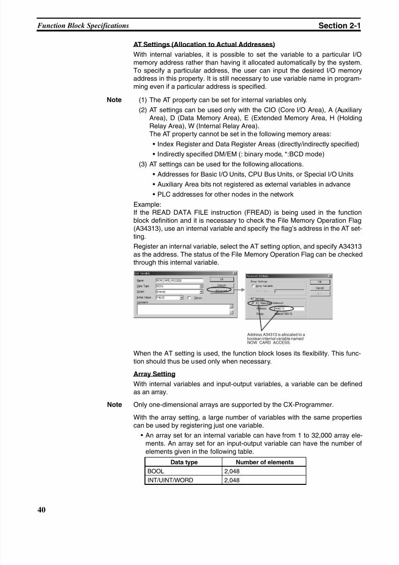
8/11/2019 CX-Programmer V9 Operation Manual FB ST.pdf
http://slidepdf.com/reader/full/cx-programmer-v9-operation-manual-fb-stpdf 66/254
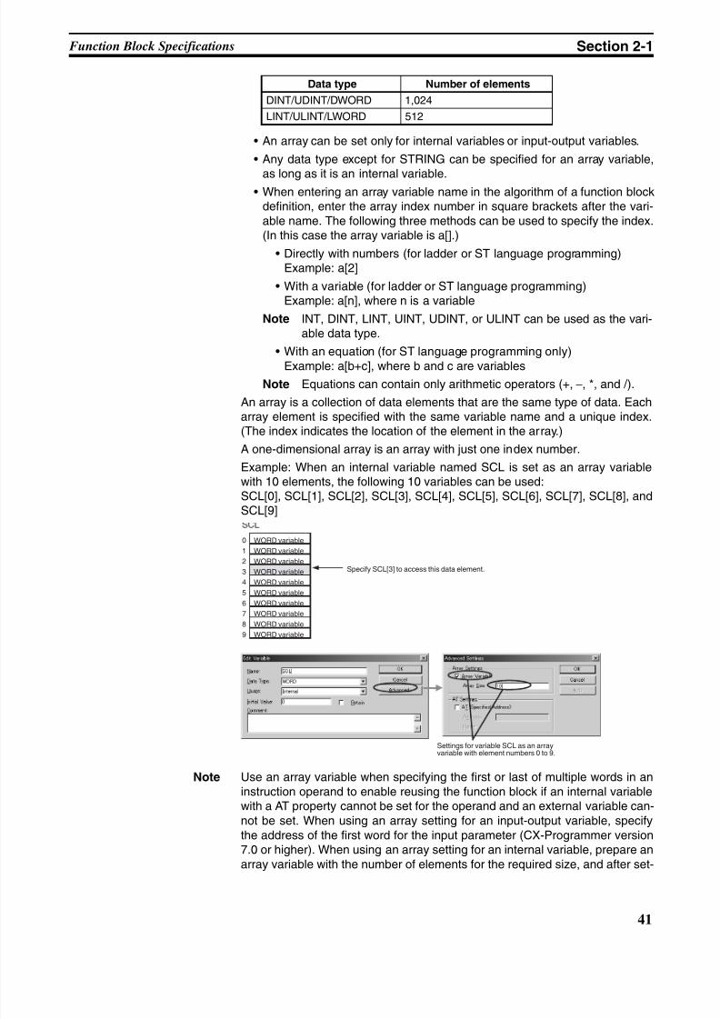
8/11/2019 CX-Programmer V9 Operation Manual FB ST.pdf
http://slidepdf.com/reader/full/cx-programmer-v9-operation-manual-fb-stpdf 67/254
41
Function Block Specifications Section 2-1
• An array can be set only for internal variables or input-output variables.
• Any data type except for STRING can be specified for an array variable,
as long as it is an internal variable.• When entering an array variable name in the algorithm of a function block
definition, enter the array index number in square brackets after the vari-able name. The following three methods can be used to specify the index.(In this case the array variable is a[].)
• Directly with numbers (for ladder or ST language programming)Example: a[2]
• With a variable (for ladder or ST language programming)Example: a[n], where n is a variable
Note INT, DINT, LINT, UINT, UDINT, or ULINT can be used as the vari-able data type.
• With an equation (for ST language programming only)Example: a[b+c], where b and c are variables
Note Equations can contain only arithmetic operators (+, −, *, and /).
An array is a collection of data elements that are the same type of data. Eacharray element is specified with the same variable name and a unique index.(The index indicates the location of the element in the array.)
A one-dimensional array is an array with just one index number.
Example: When an internal variable named SCL is set as an array variablewith 10 elements, the following 10 variables can be used:SCL[0], SCL[1], SCL[2], SCL[3], SCL[4], SCL[5], SCL[6], SCL[7], SCL[8], andSCL[9]
Note Use an array variable when specifying the first or last of multiple words in aninstruction operand to enable reusing the function block if an internal variablewith a AT property cannot be set for the operand and an external variable can-not be set. When using an array setting for an input-output variable, specifythe address of the first word for the input parameter (CX-Programmer version7.0 or higher). When using an array setting for an internal variable, prepare anarray variable with the number of elements for the required size, and after set-
DINT/UDINT/DWORD 1,024
LINT/ULINT/LWORD 512
Data type Number of elements
0
1
2
3
4
5
6
7
8
9
Specify SCL[3] to access this data element.
WORD variable
WORD variable
WORD variable
WORD variable
WORD variable
WORD variable
WORD variable
WORD variable
WORD variable
WORD variable
Settings for variable SCL as an arrayvariable with element numbers 0 to 9.
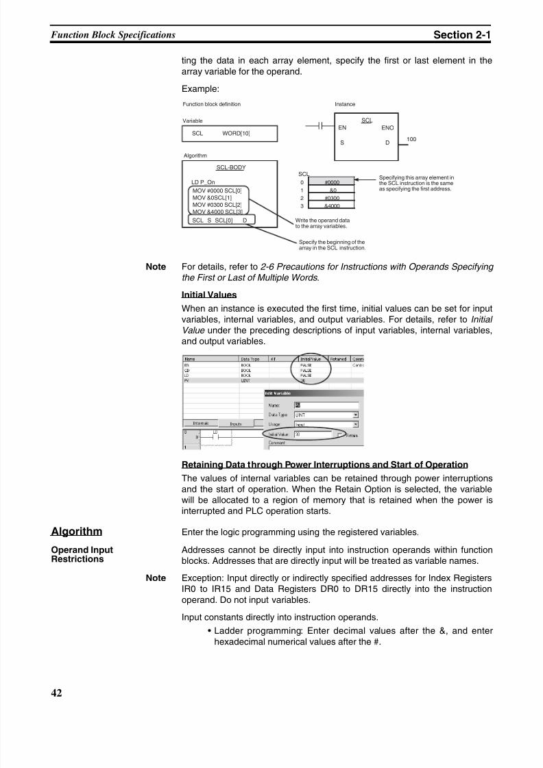
8/11/2019 CX-Programmer V9 Operation Manual FB ST.pdf
http://slidepdf.com/reader/full/cx-programmer-v9-operation-manual-fb-stpdf 68/254
42
Function Block Specifications Section 2-1
ting the data in each array element, specify the first or last element in thearray variable for the operand.
Example:
Note For details, refer to 2-6 Precautions for Instructions with Operands Specifying the First or Last of Multiple Words .
Initial Values
When an instance is executed the first time, initial values can be set for inputvariables, internal variables, and output variables. For details, refer to Initial Value under the preceding descriptions of input variables, internal variables,and output variables.
Retaining Data through Power Interruptions and Start of Operation
The values of internal variables can be retained through power interruptionsand the start of operation. When the Retain Option is selected, the variablewill be allocated to a region of memory that is retained when the power isinterrupted and PLC operation starts.
Algorithm Enter the logic programming using the registered variables.
Operand InputRestrictions
Addresses cannot be directly input into instruction operands within functionblocks. Addresses that are directly input will be treated as variable names.
Note Exception: Input directly or indirectly specified addresses for Index RegistersIR0 to IR15 and Data Registers DR0 to DR15 directly into the instructionoperand. Do not input variables.
Input constants directly into instruction operands.
• Ladder programming: Enter decimal values after the &, and enterhexadecimal numerical values after the #.
S D100
0 #0000
1 &0
2 #0300
3 &4000
Function block definition Instance
Variable
Algorithm
SCL WORD[10]
SCL-BODY
LD P_On
MOV #0000 SCL[0]
MOV &0SCL[1]
MOV #0300 SCL[2]
MOV &4000 SCL[3]
SCL S SCL[0] D
SCL
SCL
EN ENO
Write the operand datato the array variables.
Specifying this array element inthe SCL instruction is the sameas specifying the first address.
Specify the beginning of thearray in the SCL instruction.
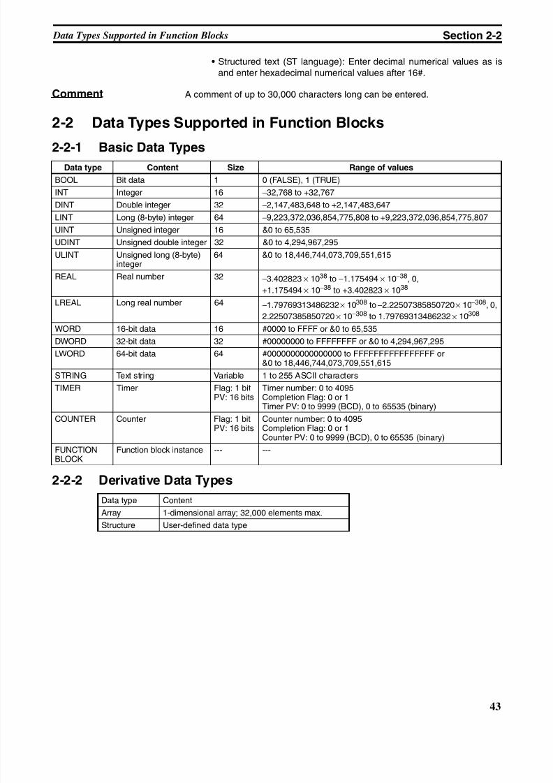
8/11/2019 CX-Programmer V9 Operation Manual FB ST.pdf
http://slidepdf.com/reader/full/cx-programmer-v9-operation-manual-fb-stpdf 69/254
43
Data Types Supported in Function Blocks Section 2-2
• Structured text (ST language): Enter decimal numerical values as isand enter hexadecimal numerical values after 16#.
Comment A comment of up to 30,000 characters long can be entered.
2-2 Data Types Supported in Function Blocks
2-2-1 Basic Data Types
2-2-2 Derivative Data Types
Data type Content Size Range of values
BOOL Bit data 1 0 (FALSE), 1 (TRUE)
INT Integer 16 −32,768 to +32,767
DINT Double integer 32 −2,147,483,648 to +2,147,483,647
LINT Long (8-byte) integer 64 −9,223,372,036,854,775,808 to +9,223,372,036,854,775,807
UINT Unsigned integer 16 &0 to 65,535
UDINT Unsigned double integer 32 &0 to 4,294,967,295
ULINT Unsigned long (8-byte)integer
64 &0 to 18,446,744,073,709,551,615
REAL Real number 32 −3.402823 × 1038 to −1.175494 × 10−38, 0,
+1.175494 × 10−38 to +3.402823 × 1038
LREAL Long real number 64 −1.79769313486232 × 10308 to−2.22507385850720 × 10−308, 0,
2.22507385850720 × 10−308 to 1.79769313486232 × 10308
WORD 16-bit data 16 #0000 to FFFF or &0 to 65,535
DWORD 32-bit data 32 #00000000 to FFFFFFFF or &0 to 4,294,967,295
LWORD 64-bit data 64 #0000000000000000 to FFFFFFFFFFFFFFFF or&0 to 18,446,744,073,709,551,615
STRING Text string Variable 1 to 255 ASCII characters
TIMER Timer Flag: 1 bitPV: 16 bits
Timer number: 0 to 4095Completion Flag: 0 or 1Timer PV: 0 to 9999 (BCD), 0 to 65535 (binary)
COUNTER Counter Flag: 1 bitPV: 16 bits
Counter number: 0 to 4095Completion Flag: 0 or 1Counter PV: 0 to 9999 (BCD), 0 to 65535 (binary)
FUNCTIONBLOCK
Function block instance --- ---
Data type Content
Array 1-dimensional array; 32,000 elements max.
Structure User-defined data type
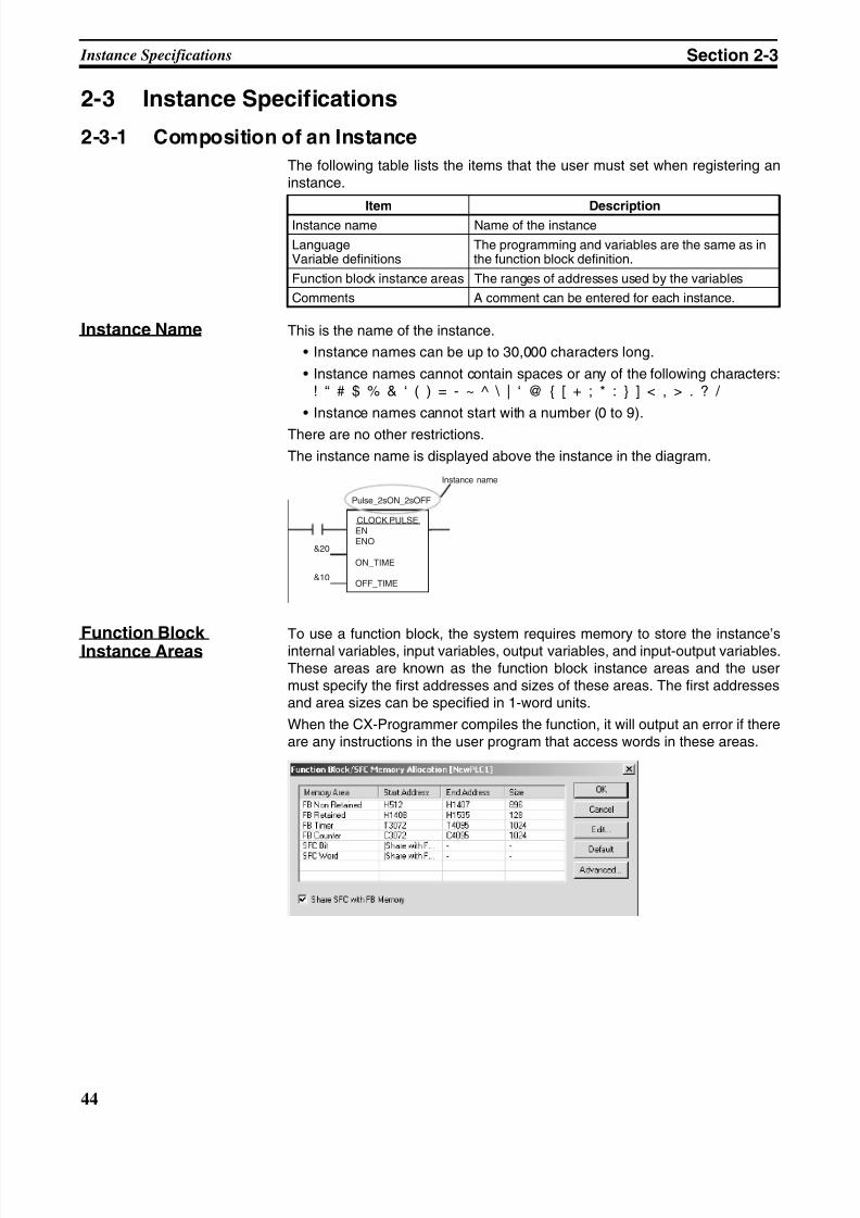
8/11/2019 CX-Programmer V9 Operation Manual FB ST.pdf
http://slidepdf.com/reader/full/cx-programmer-v9-operation-manual-fb-stpdf 70/254
44
Instance Specifications Section 2-3
2-3 Instance Specifications
2-3-1 Composition of an Instance
The following table lists the items that the user must set when registering aninstance.
Instance Name This is the name of the instance.
• Instance names can be up to 30,000 characters long.
• Instance names cannot contain spaces or any of the following characters:! “ # $ % & ‘ ( ) = - ~ ^ \ | ‘ @ { [ + ; * : } ] < , > . ? /
• Instance names cannot start with a number (0 to 9).
There are no other restrictions.
The instance name is displayed above the instance in the diagram.
Function BlockInstance Areas To use a function block, the system requires memory to store the instance’sinternal variables, input variables, output variables, and input-output variables.These areas are known as the function block instance areas and the usermust specify the first addresses and sizes of these areas. The first addressesand area sizes can be specified in 1-word units.
When the CX-Programmer compiles the function, it will output an error if thereare any instructions in the user program that access words in these areas.
Item Description
Instance name Name of the instance
LanguageVariable definitions
The programming and variables are the same as inthe function block definition.
Function block instance areas The ranges of addresses used by the variables
Comments A comment can be entered for each instance.
CLOCK PULSEENENO
ON_TIME
OFF_TIME
Pulse_2sON_2sOFF
Instance name
&20
&10
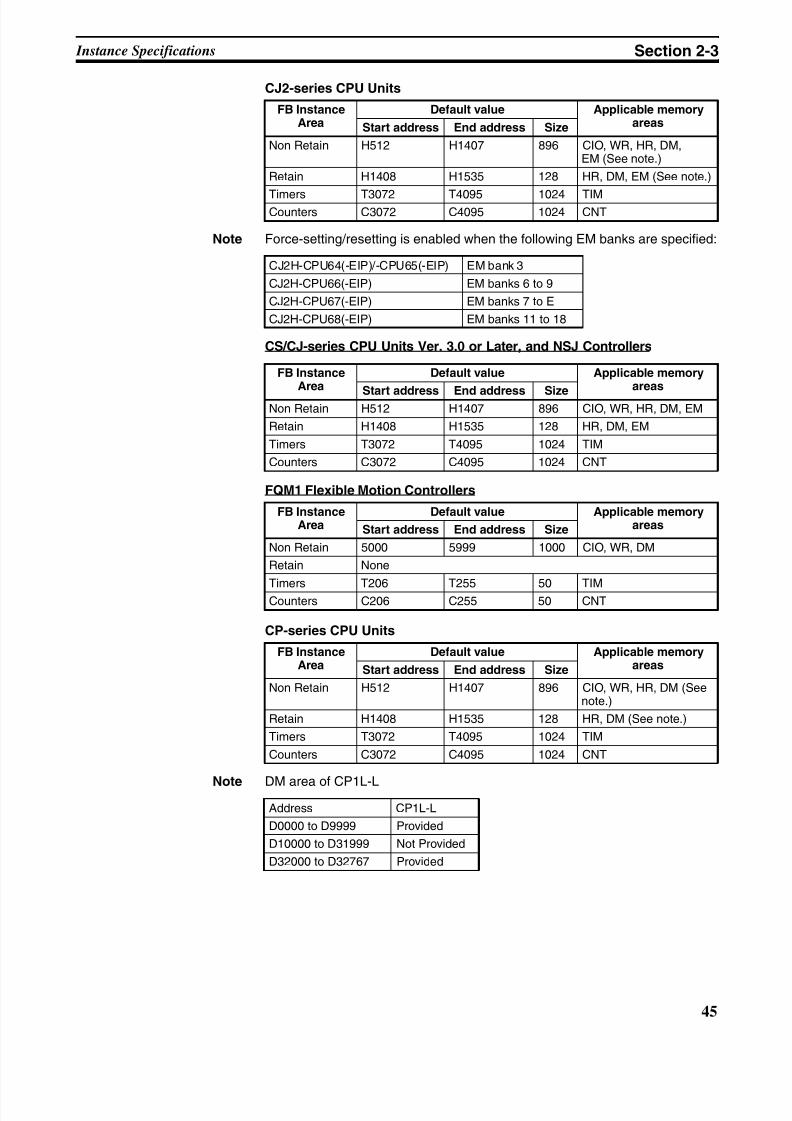
8/11/2019 CX-Programmer V9 Operation Manual FB ST.pdf
http://slidepdf.com/reader/full/cx-programmer-v9-operation-manual-fb-stpdf 71/254
45
Instance Specifications Section 2-3
CJ2-series CPU Units
Note Force-setting/resetting is enabled when the following EM banks are specified:
CS/CJ-series CPU Units Ver. 3.0 or Later, and NSJ Controllers
FQM1 Flexible Motion Controllers
CP-series CPU Units
Note DM area of CP1L-L
FB InstanceArea
Default value Applicable memoryareasStart address End address Size
Non Retain H512 H1407 896 CIO, WR, HR, DM,EM (See note.)
Retain H1408 H1535 128 HR, DM, EM (See note.)
Timers T3072 T4095 1024 TIMCounters C3072 C4095 1024 CNT
CJ2H-CPU64(-EIP)/-CPU65(-EIP) EM bank 3
CJ2H-CPU66(-EIP) EM banks 6 to 9
CJ2H-CPU67(-EIP) EM banks 7 to E
CJ2H-CPU68(-EIP) EM banks 11 to 18
FB InstanceArea
Default value Applicable memoryareas
Start address End address SizeNon Retain H512 H1407 896 CIO, WR, HR, DM, EM
Retain H1408 H1535 128 HR, DM, EM
Timers T3072 T4095 1024 TIM
Counters C3072 C4095 1024 CNT
FB InstanceArea
Default value Applicable memoryareasStart address End address Size
Non Retain 5000 5999 1000 CIO, WR, DM
Retain None
Timers T206 T255 50 TIMCounters C206 C255 50 CNT
FB InstanceArea
Default value Applicable memoryareasStart address End address Size
Non Retain H512 H1407 896 CIO, WR, HR, DM (Seenote.)
Retain H1408 H1535 128 HR, DM (See note.)
Timers T3072 T4095 1024 TIM
Counters C3072 C4095 1024 CNT
Address CP1L-L
D0000 to D9999 Provided
D10000 to D31999 Not Provided
D32000 to D32767 Provided
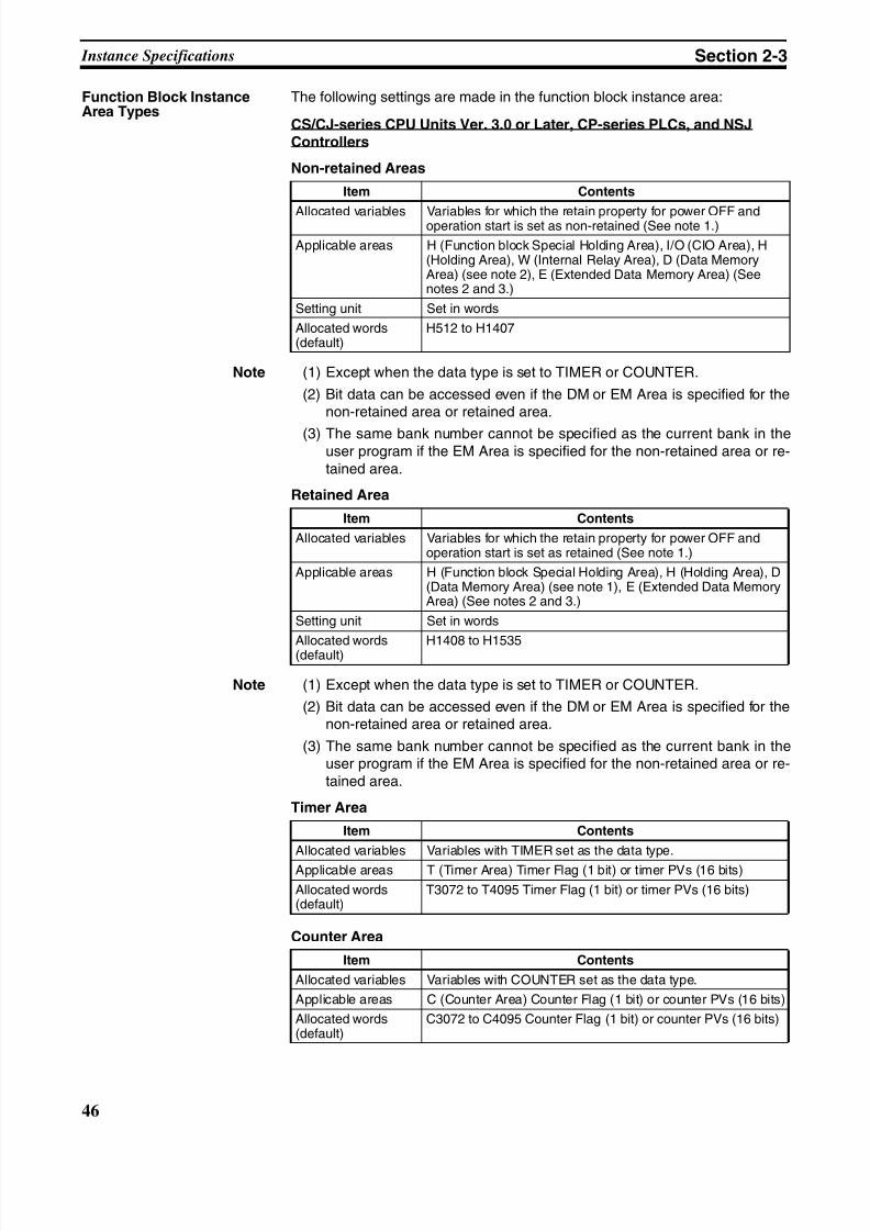
8/11/2019 CX-Programmer V9 Operation Manual FB ST.pdf
http://slidepdf.com/reader/full/cx-programmer-v9-operation-manual-fb-stpdf 72/254
46
Instance Specifications Section 2-3
Function Block InstanceArea Types
The following settings are made in the function block instance area:
CS/CJ-series CPU Units Ver. 3.0 or Later, CP-series PLCs, and NSJControllers
Non-retained Areas
Note (1) Except when the data type is set to TIMER or COUNTER.
(2) Bit data can be accessed even if the DM or EM Area is specified for thenon-retained area or retained area.
(3) The same bank number cannot be specified as the current bank in theuser program if the EM Area is specified for the non-retained area or re-tained area.
Retained Area
Note (1) Except when the data type is set to TIMER or COUNTER.
(2) Bit data can be accessed even if the DM or EM Area is specified for thenon-retained area or retained area.
(3) The same bank number cannot be specified as the current bank in theuser program if the EM Area is specified for the non-retained area or re-tained area.
Timer Area
Counter Area
Item Contents
Allocated variables Variables for which the retain property for power OFF andoperation start is set as non-retained (See note 1.)
Applicable areas H (Function block Special Holding Area), I/O (CIO Area), H(Holding Area), W (Internal Relay Area), D (Data MemoryArea) (see note 2), E (Extended Data Memory Area) (Seenotes 2 and 3.)
Setting unit Set in words
Allocated words(default)
H512 to H1407
Item Contents
Allocated variables Variables for which the retain property for power OFF andoperation start is set as retained (See note 1.)
Applicable areas H (Function block Special Holding Area), H (Holding Area), D(Data Memory Area) (see note 1), E (Extended Data MemoryArea) (See notes 2 and 3.)
Setting unit Set in words
Allocated words(default) H1408 to H1535
Item Contents
Allocated variables Variables with TIMER set as the data type.
Applicable areas T (Timer Area) Timer Flag (1 bit) or timer PVs (16 bits)
Allocated words(default)
T3072 to T4095 Timer Flag (1 bit) or timer PVs (16 bits)
Item Contents
Allocated variables Variables with COUNTER set as the data type.
Applicable areas C (Counter Area) Counter Flag (1 bit) or counter PVs (16 bits)
Allocated words(default)
C3072 to C4095 Counter Flag (1 bit) or counter PVs (16 bits)
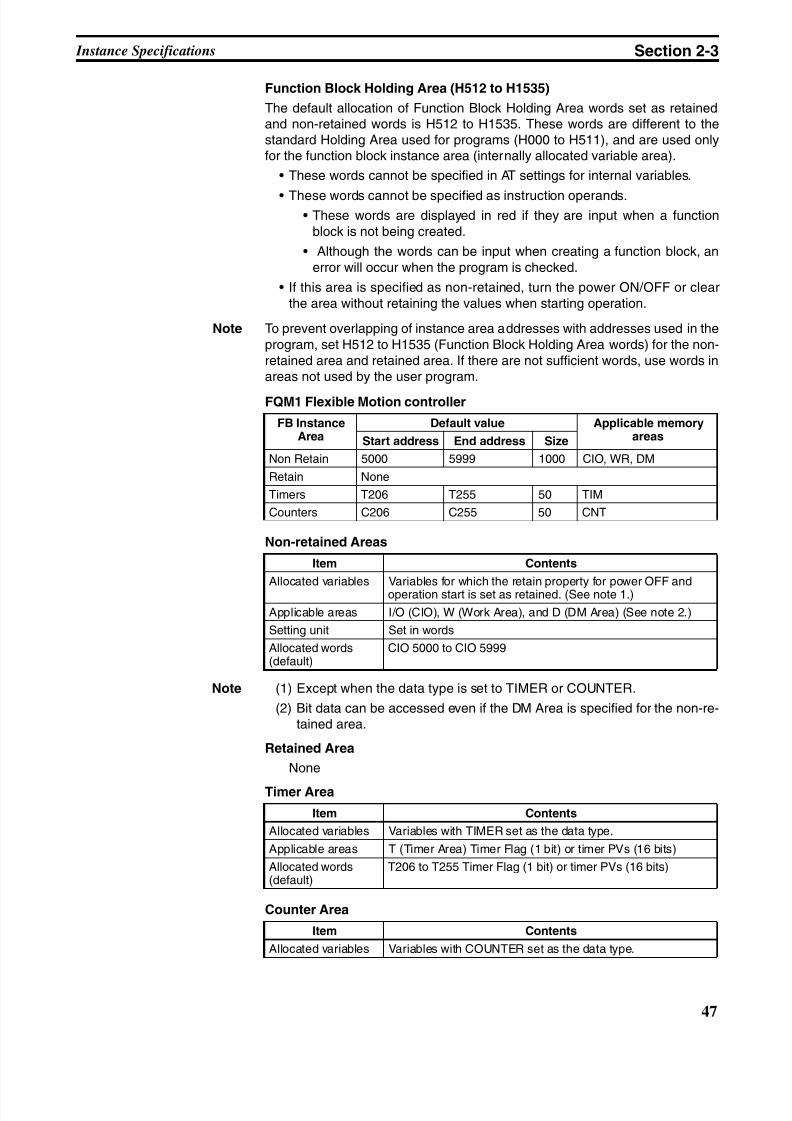
8/11/2019 CX-Programmer V9 Operation Manual FB ST.pdf
http://slidepdf.com/reader/full/cx-programmer-v9-operation-manual-fb-stpdf 73/254
47
Instance Specifications Section 2-3
Function Block Holding Area (H512 to H1535)
The default allocation of Function Block Holding Area words set as retainedand non-retained words is H512 to H1535. These words are different to thestandard Holding Area used for programs (H000 to H511), and are used onlyfor the function block instance area (internally allocated variable area).
• These words cannot be specified in AT settings for internal variables.
• These words cannot be specified as instruction operands.• These words are displayed in red if they are input when a function
block is not being created.
• Although the words can be input when creating a function block, anerror will occur when the program is checked.
• If this area is specified as non-retained, turn the power ON/OFF or clearthe area without retaining the values when starting operation.
Note To prevent overlapping of instance area addresses with addresses used in theprogram, set H512 to H1535 (Function Block Holding Area words) for the non-retained area and retained area. If there are not sufficient words, use words inareas not used by the user program.
FQM1 Flexible Motion controller
Non-retained Areas
Note (1) Except when the data type is set to TIMER or COUNTER.
(2) Bit data can be accessed even if the DM Area is specified for the non-re-tained area.
Retained Area
None
Timer Area
Counter Area
FB InstanceArea
Default value Applicable memoryareasStart address End address Size
Non Retain 5000 5999 1000 CIO, WR, DM
Retain None
Timers T206 T255 50 TIM
Counters C206 C255 50 CNT
Item Contents
Allocated variables Variables for which the retain property for power OFF andoperation start is set as retained. (See note 1.)
Applicable areas I/O (CIO), W (Work Area), and D (DM Area) (See note 2.)
Setting unit Set in words
Allocated words(default)
CIO 5000 to CIO 5999
Item Contents
Allocated variables Variables with TIMER set as the data type.
Applicable areas T (Timer Area) Timer Flag (1 bit) or timer PVs (16 bits)
Allocated words(default)
T206 to T255 Timer Flag (1 bit) or timer PVs (16 bits)
Item Contents
Allocated variables Variables with COUNTER set as the data type.
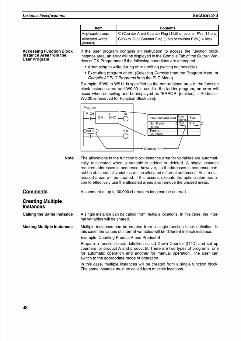
8/11/2019 CX-Programmer V9 Operation Manual FB ST.pdf
http://slidepdf.com/reader/full/cx-programmer-v9-operation-manual-fb-stpdf 74/254
48
Instance Specifications Section 2-3
Accessing Function BlockInstance Area from the
User Program
If the user program contains an instruction to access the function blockinstance area, an error will be displayed in the Compile Tab of the Output Win-
dow of CX-Programmer if the following operations are attempted.
• Attempting to write during online editing (writing not possible)
• Executing program check (Selecting Compile from the Program Menu orCompile All PLC Programs from the PLC Menu)
Example: If W0 to W511 is specified as the non-retained area of the functionblock instance area and W0.00 is used in the ladder program, an error willoccur when compiling and be displayed as “ERROR: [omitted]...- Address -W0.00 is reserved for Function Block use].
Note The allocations in the function block instance area for variables are automati-cally reallocated when a variable is added or deleted. A single instancerequires addresses in sequence, however, so if addresses in sequence can-not be obtained, all variables will be allocated different addresses. As a result,
unused areas will be created. If this occurs, execute the optimization opera-tion to effectively use the allocated areas and remove the unused areas.
Comments A comment of up to 30,000 characters long can be entered.
Creating MultipleInstances
Calling the Same Instance A single instance can be called from multiple locations. In this case, the inter-nal variables will be shared.
Making Multiple Instances Multiple instances can be created from a single function block definition. Inthis case, the values of internal variables will be different in each instance.
Example: Counting Product A and Product BPrepare a function block definition called Down Counter (CTD) and set upcounters for product A and product B. There are two types of programs, onefor automatic operation and another for manual operation. The user canswitch to the appropriate mode of operation.
In this case, multiple instances will be created from a single function block.The same instance must be called from multiple locations.
Applicable areas C (Counter Area) Counter Flag (1 bit) or counter PVs (16 bits)
Allocated words(default)
C206 to C255 Counter Flag (1 bit) or counter PVs (16 bits)
Item Contents
FBEN ENO
1.0P_Off
3.0W0.00
W0 512
Program
Compile error
Instance data area
Non RetainRetainTimersCounters
Start
addressSize
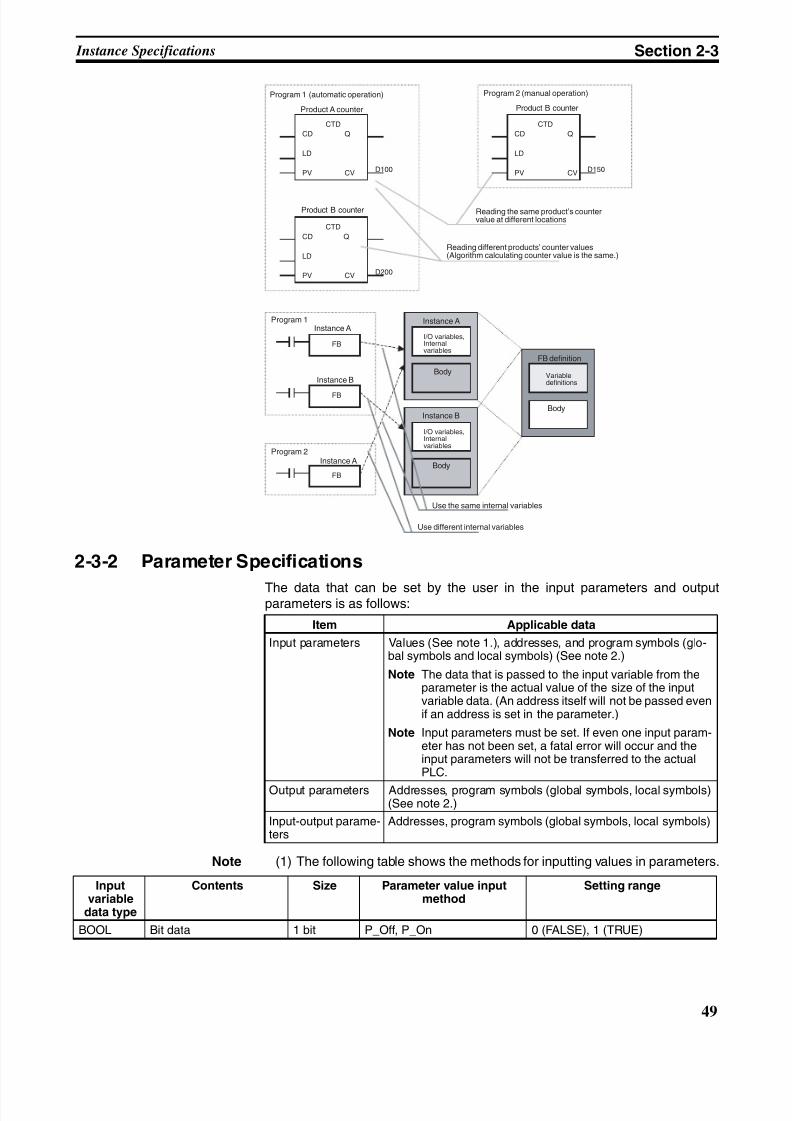
8/11/2019 CX-Programmer V9 Operation Manual FB ST.pdf
http://slidepdf.com/reader/full/cx-programmer-v9-operation-manual-fb-stpdf 75/254
49
Instance Specifications Section 2-3
2-3-2 Parameter Specifications
The data that can be set by the user in the input parameters and outputparameters is as follows:
Note (1) The following table shows the methods for inputting values in parameters.
CTD
CD Q
LD
PV CV D100
CTD
CD Q
LD
PV CV D200
CTD
CD Q
LD
PV CV D150
FB
FB
FB
Program 1 (automatic operation) Program 2 (manual operation)
Product A counter Product B counter
Product B counter
Program 1Instance A
Instance B
Program 2Instance A
Reading the same product’s countervalue at different locations
Reading different products’ counter values(Algorithm calculating counter value is the same.)
Use the same internal variables
Use different internal variables
Instance A
Instance B
I/O variables,Internalvariables
Body
I/O variables,Internalvariables
Body
FB definition
Variabledefinitions
Body
Item Applicable data
Input parameters Values (See note 1.), addresses, and program symbols (glo-bal symbols and local symbols) (See note 2.)
Note The data that is passed to the input variable from theparameter is the actual value of the size of the inputvariable data. (An address itself will not be passed evenif an address is set in the parameter.)
Note Input parameters must be set. If even one input param-eter has not been set, a fatal error will occur and theinput parameters will not be transferred to the actualPLC.
Output parameters Addresses, program symbols (global symbols, local symbols)(See note 2.)
Input-output parame-ters
Addresses, program symbols (global symbols, local symbols)
Inputvariable
data type
Contents Size Parameter value inputmethod
Setting range
BOOL Bit data 1 bit P_Off, P_On 0 (FALSE), 1 (TRUE)
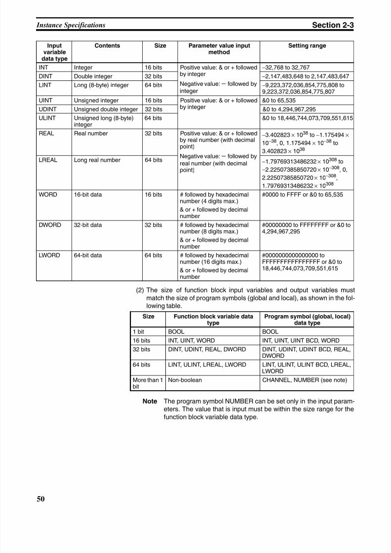
8/11/2019 CX-Programmer V9 Operation Manual FB ST.pdf
http://slidepdf.com/reader/full/cx-programmer-v9-operation-manual-fb-stpdf 76/254
50
Instance Specifications Section 2-3
(2) The size of function block input variables and output variables mustmatch the size of program symbols (global and local), as shown in the fol-lowing table.
Note The program symbol NUMBER can be set only in the input param-eters. The value that is input must be within the size range for thefunction block variable data type.
INT Integer 16 bits Positive value: & or + followedby integer
Negative value: − followed byinteger
−32,768 to 32,767
DINT Double integer 32 bits −2,147,483,648 to 2,147,483,647
LINT Long (8-byte) integer 64 bits −9,223,372,036,854,775,808 to9,223,372,036,854,775,807
UINT Unsigned integer 16 bits Positive value: & or + followedby integer
&0 to 65,535
UDINT Unsigned double integer 32 bits &0 to 4,294,967,295
ULINT Unsigned long (8-byte)integer
64 bits &0 to 18,446,744,073,709,551,615
REAL Real number 32 bits Positive value: & or + followedby real number (with decimalpoint)
Negative value: − followed byreal number (with decimalpoint)
−3.402823 × 1038 to −1.175494 ×
10−38, 0, 1.175494 × 10−38 to
3.402823 × 1038
LREAL Long real number 64 bits −1.79769313486232 × 10308 to
−2.22507385850720 × 10−308, 0,
2.22507385850720 × 10−308,
1.79769313486232 × 10308
WORD 16-bit data 16 bits # followed by hexadecimalnumber (4 digits max.)
& or + followed by decimalnumber
#0000 to FFFF or &0 to 65,535
DWORD 32-bit data 32 bits # followed by hexadecimalnumber (8 digits max.)
& or + followed by decimalnumber
#00000000 to FFFFFFFF or &0 to4,294,967,295
LWORD 64-bit data 64 bits # followed by hexadecimalnumber (16 digits max.)
& or + followed by decimalnumber
#0000000000000000 toFFFFFFFFFFFFFFFF or &0 to18,446,744,073,709,551,615
Inputvariable
data type
Contents Size Parameter value inputmethod
Setting range
Size Function block variable datatype
Program symbol (global, local)data type
1 bit BOOL BOOL
16 bits INT, UINT, WORD INT, UINT, UINT BCD, WORD
32 bits DINT, UDINT, REAL, DWORD DINT, UDINT, UDINT BCD, REAL,DWORD
64 bits LINT, ULINT, LREAL, LWORD LINT, ULINT, ULINT BCD, LREAL,LWORD
More than 1
bit
Non-boolean CHANNEL, NUMBER (see note)
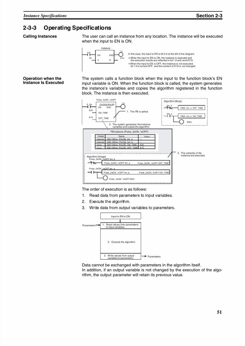
8/11/2019 CX-Programmer V9 Operation Manual FB ST.pdf
http://slidepdf.com/reader/full/cx-programmer-v9-operation-manual-fb-stpdf 77/254
51
Instance Specifications Section 2-3
2-3-3 Operating Specifications
Calling Instances The user can call an instance from any location. The instance will be executedwhen the input to EN is ON.
Operation when theInstance Is Executed
The system calls a function block when the input to the function block’s ENinput variable is ON. When the function block is called, the system generatesthe instance’s variables and copies the algorithm registered in the functionblock. The instance is then executed.
The order of execution is as follows:
1. Read data from parameters to input variables.
2. Execute the algorithm.
3. Write data from output variables to parameters.
Data cannot be exchanged with parameters in the algorithm itself.In addition, if an output variable is not changed by the execution of the algo-rithm, the output parameter will retain its previous value.
0.01.0
D10
EN ENO
A B
D0
Instance
In this case, the input to EN is bit 0.0 at the left of the diagram.
• When the input to EN is ON, the instance is executed and
the execution results are reflected in bit 1.0 and word D10.• When the input to EN is OFF, the instance is not executed,
bit 1.0 is turned OFF, and the content of D10 is not changed.
P_On1.0
&10
CLOCK PULSE
EN ENO
ON_TIME
OFF_TIME
&20
Pulse_2sON_1sOFF
---
---
&20
&10
TIMX tim_a OFF_TIMEtim_b
TIMX tim_b ON_TIMEtim_a
ENO
1. The FB is called.
2. The system generates the instancevariables and copies the algorithm.
FB instance (Pulse_2sON_1sOFF)
Algorithm (Body)
Name
Internal
Internal
Input
Input
Value200-100ms_PULSE_tim_a
200-100ms_PULSE_tim_b
200-100ms_PULSE_ON_TIME
200-100ms_PULSE_OFF_TIME
3. The contents of theinstance are executed.Algorithm (Image)
Pulse_2sON_1sOFF tim_a Pulse_2sON_1sOFF OFF_TIME
Pulse_2sON_1sOFF t im_b Pulse_2sON_1sOFF ON_TIME
Pulse_2sON_1sOFF ENO
Pulse_2sON_1sOFF tim_b
Pulse_2sON_1sOFF tim_a
Usage
Input to EN is ON.
Parameters 1. Read values from parametersto input variables.
2. Execute the algorithm.
3. Write values from outputvariables to parameters.
Parameters
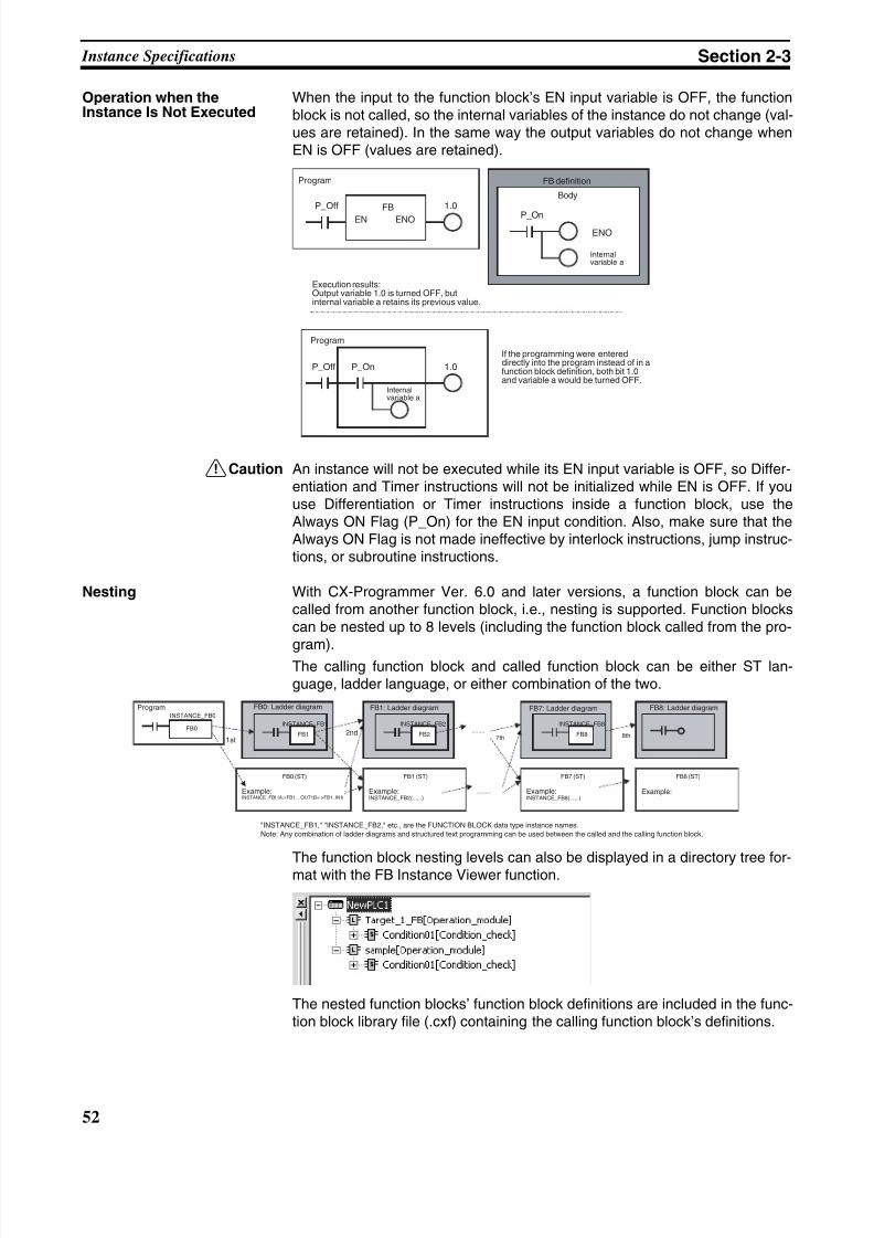
8/11/2019 CX-Programmer V9 Operation Manual FB ST.pdf
http://slidepdf.com/reader/full/cx-programmer-v9-operation-manual-fb-stpdf 78/254
52
Instance Specifications Section 2-3
Operation when theInstance Is Not Executed
When the input to the function block’s EN input variable is OFF, the functionblock is not called, so the internal variables of the instance do not change (val-ues are retained). In the same way the output variables do not change whenEN is OFF (values are retained).
!Caution An instance will not be executed while its EN input variable is OFF, so Differ-entiation and Timer instructions will not be initialized while EN is OFF. If youuse Differentiation or Timer instructions inside a function block, use theAlways ON Flag (P_On) for the EN input condition. Also, make sure that theAlways ON Flag is not made ineffective by interlock instructions, jump instruc-tions, or subroutine instructions.
Nesting With CX-Programmer Ver. 6.0 and later versions, a function block can becalled from another function block, i.e., nesting is supported. Function blockscan be nested up to 8 levels (including the function block called from the pro-
gram).The calling function block and called function block can be either ST lan-guage, ladder language, or either combination of the two.
The function block nesting levels can also be displayed in a directory tree for-mat with the FB Instance Viewer function.
The nested function blocks’ function block definitions are included in the func-tion block library file (.cxf) containing the calling function block’s definitions.
FB
EN ENO
1.0P_Off
P_On
ENO
1.0P_Off P_On
Program FB definition
Body
Execution results:Output variable 1.0 is turned OFF, butinternal variable a retains its previous value.
If the programming were entereddirectly into the program instead of in afunction block definition, both bit 1.0and variable a would be turned OFF.
Program
Internalvariable a
Internalvariable a
FB0
INSTANCE_FB0
FB1
FB0 (ST)
Example:INSTANCE_FB1 (A:=FB1__OUT1,B=:>FB1_IN1)
;
INSTANCE_FB1
FB2
INSTANCE_FB2
FB8
INSTANCE_FB8
7th
FB1 (ST)
Example:INSTANCE_FB2 (...,..)
FB7 (ST)
Example:INSTANCE_FB8 (...,..)
8th
FB8 (ST)
Example:
Program FB0: Ladder diagram FB1: Ladder diagram FB7: Ladder diagram FB8: Ladder diagram
1st2nd
"INSTANCE_FB1," "INSTANCE_FB2," etc., are the FUNCTION BLOCK data type instance names.Note: Any combination of ladder diagrams and structured text programming can be used between the called and the calling function block.
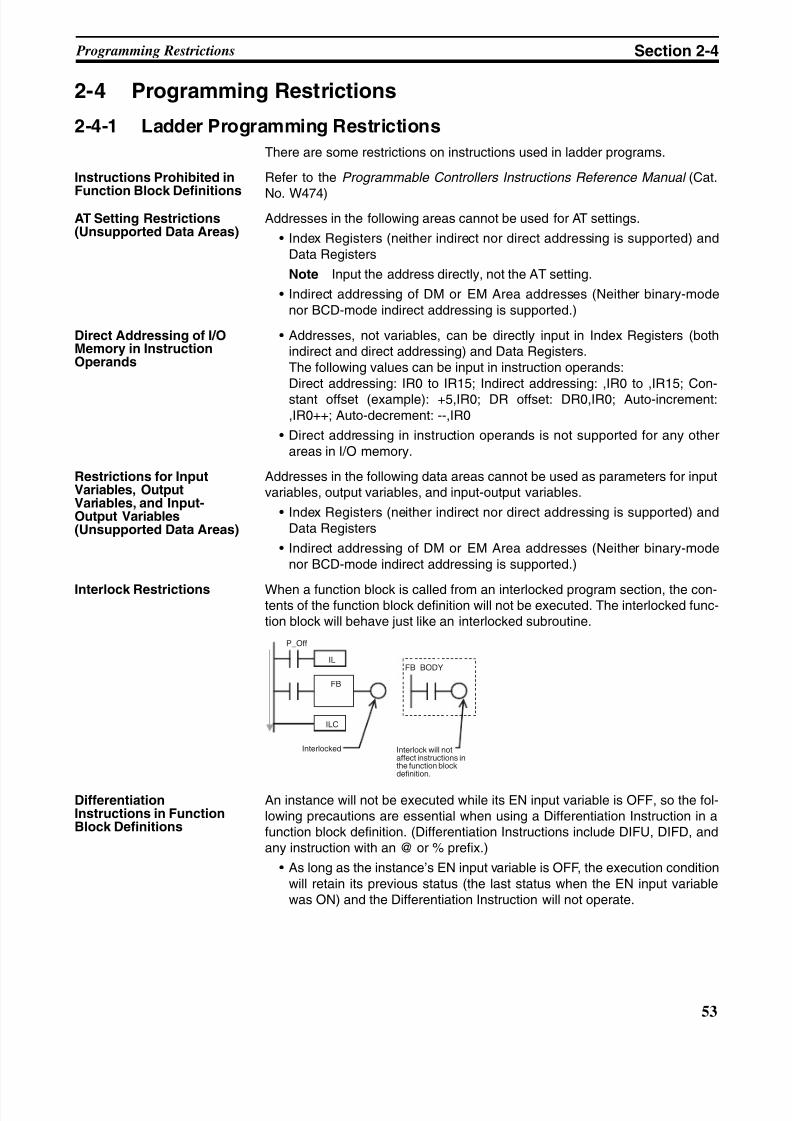
8/11/2019 CX-Programmer V9 Operation Manual FB ST.pdf
http://slidepdf.com/reader/full/cx-programmer-v9-operation-manual-fb-stpdf 79/254
53
Programming Restrictions Section 2-4
2-4 Programming Restrictions
2-4-1 Ladder Programming Restrictions
There are some restrictions on instructions used in ladder programs.
Instructions Prohibited in
Function Block Definitions
Refer to the Programmable Controllers Instructions Reference Manual (Cat.
No. W474)AT Setting Restrictions(Unsupported Data Areas)
Addresses in the following areas cannot be used for AT settings.
• Index Registers (neither indirect nor direct addressing is supported) andData Registers
Note Input the address directly, not the AT setting.
• Indirect addressing of DM or EM Area addresses (Neither binary-modenor BCD-mode indirect addressing is supported.)
Direct Addressing of I/OMemory in InstructionOperands
• Addresses, not variables, can be directly input in Index Registers (bothindirect and direct addressing) and Data Registers.The following values can be input in instruction operands:Direct addressing: IR0 to IR15; Indirect addressing: ,IR0 to ,IR15; Con-stant offset (example): +5,IR0; DR offset: DR0,IR0; Auto-increment:,IR0++; Auto-decrement: --,IR0
• Direct addressing in instruction operands is not supported for any otherareas in I/O memory.
Restrictions for InputVariables, OutputVariables, and Input-Output Variables(Unsupported Data Areas)
Addresses in the following data areas cannot be used as parameters for inputvariables, output variables, and input-output variables.
• Index Registers (neither indirect nor direct addressing is supported) andData Registers
• Indirect addressing of DM or EM Area addresses (Neither binary-modenor BCD-mode indirect addressing is supported.)
Interlock Restrictions When a function block is called from an interlocked program section, the con-tents of the function block definition will not be executed. The interlocked func-tion block will behave just like an interlocked subroutine.
DifferentiationInstructions in FunctionBlock Definitions
An instance will not be executed while its EN input variable is OFF, so the fol-lowing precautions are essential when using a Differentiation Instruction in afunction block definition. (Differentiation Instructions include DIFU, DIFD, andany instruction with an @ or % prefix.)
• As long as the instance’s EN input variable is OFF, the execution conditionwill retain its previous status (the last status when the EN input variablewas ON) and the Differentiation Instruction will not operate.
FB
IL
P_Off
ILC
FB_BODY
Interlocked Interlock will notaffect instructions inthe function blockdefinition.
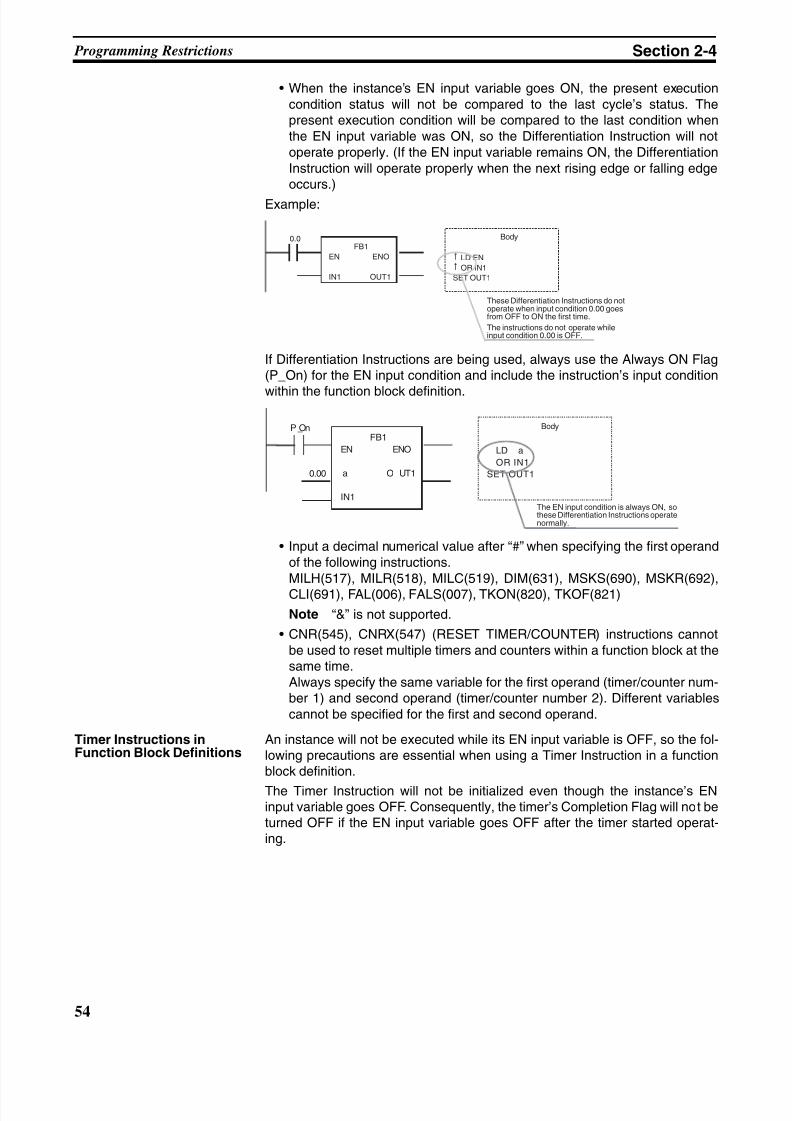
8/11/2019 CX-Programmer V9 Operation Manual FB ST.pdf
http://slidepdf.com/reader/full/cx-programmer-v9-operation-manual-fb-stpdf 80/254
54
Programming Restrictions Section 2-4
• When the instance’s EN input variable goes ON, the present executioncondition status will not be compared to the last cycle’s status. Thepresent execution condition will be compared to the last condition whenthe EN input variable was ON, so the Differentiation Instruction will notoperate properly. (If the EN input variable remains ON, the DifferentiationInstruction will operate properly when the next rising edge or falling edgeoccurs.)
Example:
If Differentiation Instructions are being used, always use the Always ON Flag(P_On) for the EN input condition and include the instruction’s input condition
within the function block definition.
• Input a decimal numerical value after “#” when specifying the first operandof the following instructions.MILH(517), MILR(518), MILC(519), DIM(631), MSKS(690), MSKR(692),
CLI(691), FAL(006), FALS(007), TKON(820), TKOF(821)
Note “&” is not supported.
• CNR(545), CNRX(547) (RESET TIMER/COUNTER) instructions cannotbe used to reset multiple timers and counters within a function block at thesame time.Always specify the same variable for the first operand (timer/counter num-ber 1) and second operand (timer/counter number 2). Different variablescannot be specified for the first and second operand.
Timer Instructions inFunction Block Definitions
An instance will not be executed while its EN input variable is OFF, so the fol-lowing precautions are essential when using a Timer Instruction in a functionblock definition.
The Timer Instruction will not be initialized even though the instance’s ENinput variable goes OFF. Consequently, the timer’s Completion Flag will not beturned OFF if the EN input variable goes OFF after the timer started operat-ing.
FB1
EN ENO
IN1 OUT1
0.0
LD EN
OR IN1
SET OUT1
These Differentiation Instructions do notoperate when input condition 0.00 goesfrom OFF to ON the first time.
The instructions do not operate whileinput condition 0.00 is OFF.
Body
FB1
EN ENO
a O UT1
IN1
P_On
LD a
OR IN1
SET OUT10.00
The EN input condition is always ON, sothese Differentiation Instructions operatenormally.
Body
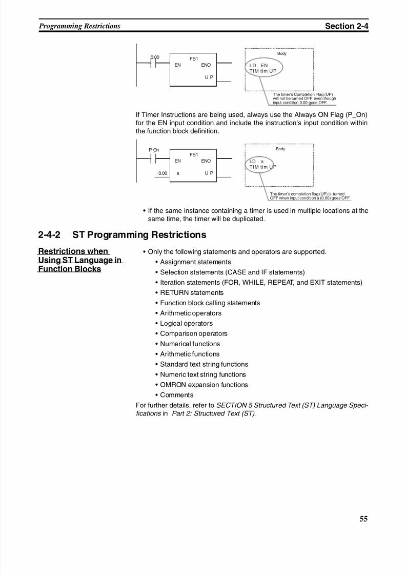
8/11/2019 CX-Programmer V9 Operation Manual FB ST.pdf
http://slidepdf.com/reader/full/cx-programmer-v9-operation-manual-fb-stpdf 81/254
55
Programming Restrictions Section 2-4
If Timer Instructions are being used, always use the Always ON Flag (P_On)for the EN input condition and include the instruction’s input condition withinthe function block definition.
• If the same instance containing a timer is used in multiple locations at thesame time, the timer will be duplicated.
2-4-2 ST Programming Restrictions
Restrictions whenUsing ST Language inFunction Blocks
• Only the following statements and operators are supported.
• Assignment statements
• Selection statements (CASE and IF statements)
• Iteration statements (FOR, WHILE, REPEAT, and EXIT statements)
• RETURN statements
• Function block calling statements• Arithmetic operators
• Logical operators
• Comparison operators
• Numerical functions
• Arithmetic functions
• Standard text string functions
• Numeric text string functions
• OMRON expansion functions
• Comments
For further details, refer to SECTION 5 Structured Text (ST) Language Speci- fications in Part 2: Structured Text (ST) .
FB1
EN ENO
U P
LD ENTIM t im UP
0.00
The timer’s Completion Flag (UP)
will not be turned OFF even thoughinput condition 0.00 goes OFF.
Body
FB1
EN ENO
a U P
P_On
LD aTIM t im UP
0.00
The timer’s completion flag (UP) is turnedOFF when input condition a (0.00) goes OFF.
Body
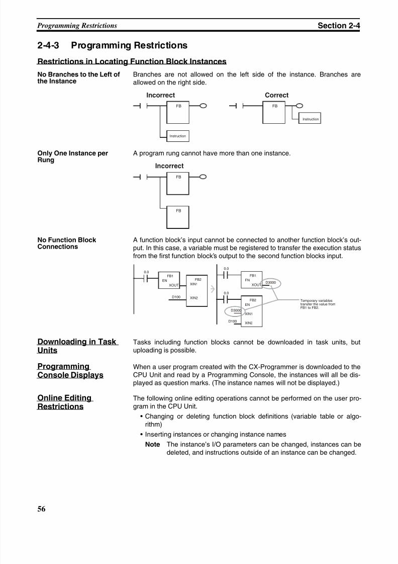
8/11/2019 CX-Programmer V9 Operation Manual FB ST.pdf
http://slidepdf.com/reader/full/cx-programmer-v9-operation-manual-fb-stpdf 82/254
56
Programming Restrictions Section 2-4
2-4-3 Programming Restrictions
Restrictions in Locating Function Block Instances
No Branches to the Left ofthe Instance
Branches are not allowed on the left side of the instance. Branches areallowed on the right side.
Only One Instance perRung
A program rung cannot have more than one instance.
No Function BlockConnections
A function block’s input cannot be connected to another function block’s out-put. In this case, a variable must be registered to transfer the execution statusfrom the first function block’s output to the second function blocks input.
Downloading in TaskUnits
Tasks including function blocks cannot be downloaded in task units, butuploading is possible.
ProgrammingConsole Displays
When a user program created with the CX-Programmer is downloaded to theCPU Unit and read by a Programming Console, the instances will all be dis-played as question marks. (The instance names will not be displayed.)
Online EditingRestrictions
The following online editing operations cannot be performed on the user pro-gram in the CPU Unit.
• Changing or deleting function block definitions (variable table or algo-rithm)
• Inserting instances or changing instance names
Note The instance’s I/O parameters can be changed, instances can bedeleted, and instructions outside of an instance can be changed.
FB FBIncorrect Correct
Instruction
Instruction
FB
FB FB
Incorrect Correct
FB1
EN
XOUT
FB2
XIN1
XIN2D100
0.0FB1
EN
XOUT
FB2
EN
XIN1
XIN2D100
0.0
D3000
D3000
0.0
Temporary variablestransfer the value fromFB1 to FB2.
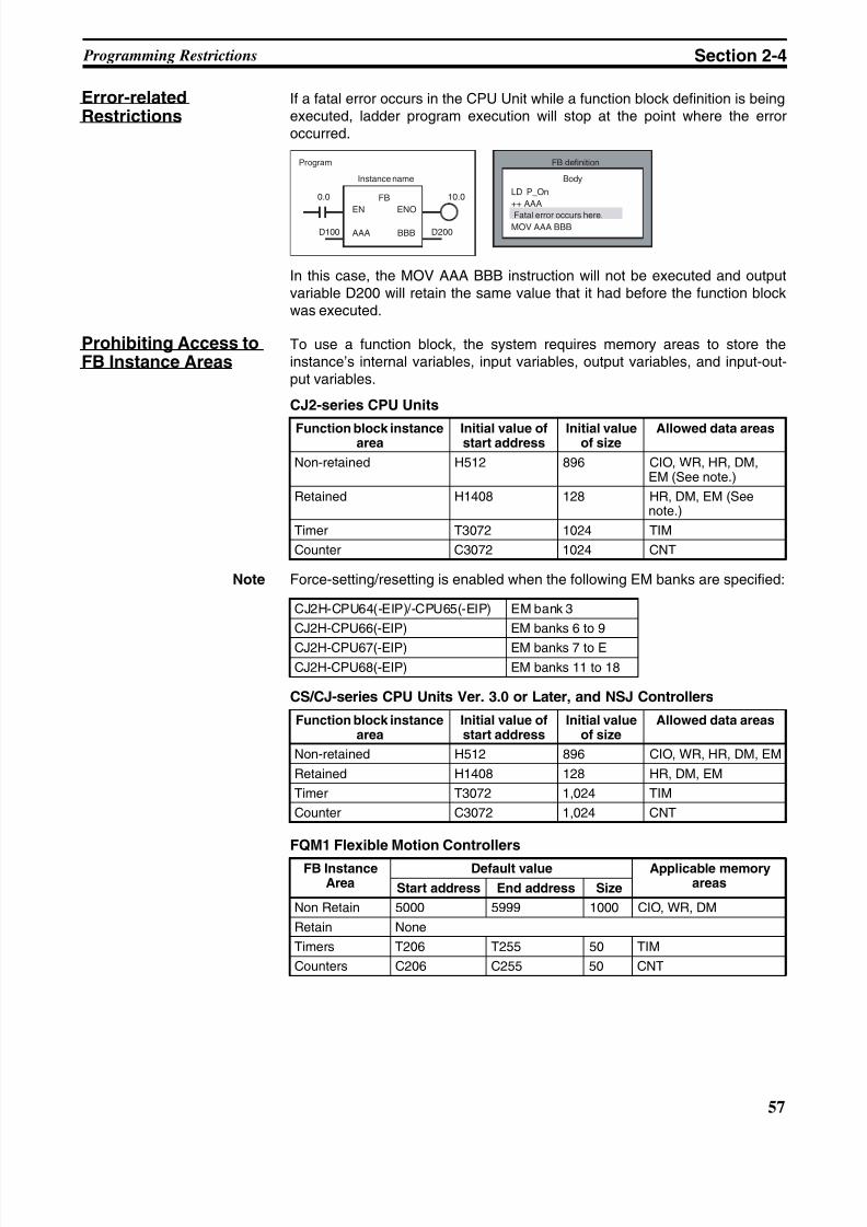
8/11/2019 CX-Programmer V9 Operation Manual FB ST.pdf
http://slidepdf.com/reader/full/cx-programmer-v9-operation-manual-fb-stpdf 83/254
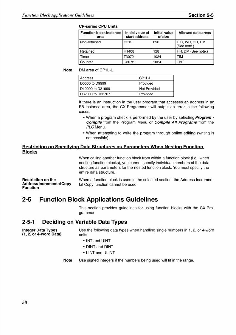
8/11/2019 CX-Programmer V9 Operation Manual FB ST.pdf
http://slidepdf.com/reader/full/cx-programmer-v9-operation-manual-fb-stpdf 84/254
58
Function Block Applications Guidelines Section 2-5
CP-series CPU Units
Note DM area of CP1L-L
If there is an instruction in the user program that accesses an address in anFB instance area, the CX-Programmer will output an error in the followingcases.
• When a program check is performed by the user by selecting Program - Compile from the Program Menu or Compile All Programs from thePLC Menu.
• When attempting to write the program through online editing (writing isnot possible).
Restriction on Specifying Data Structures as Parameters When Nesting FunctionBlocks
When calling another function block from within a function block (i.e., whennesting function blocks), you cannot specify individual members of the datastructure as parameters for the nested function block. You must specify theentire data structure.
Restriction on theAddress Incremental CopyFunction
When a function block is used in the selected section, the Address Incremen-tal Copy function cannot be used.
2-5 Function Block Applications Guidelines
This section provides guidelines for using function blocks with the CX-Pro-grammer.
2-5-1 Deciding on Variable Data Types
Integer Data Types
(1, 2, or 4-word Data)
Use the following data types when handling single numbers in 1, 2, or 4-word
units.• INT and UINT
• DINT and DINT
• LINT and ULINT
Note Use signed integers if the numbers being used will fit in the range.
Function block instancearea
Initial value ofstart address
Initial valueof size
Allowed data areas
Non-retained H512 896 CIO, WR, HR, DM(See note.)
Retained H1408 128 HR, DM (See note.)
Timer T3072 1024 TIMCounter C3072 1024 CNT
Address CP1L-L
D0000 to D9999 Provided
D10000 to D31999 Not Provided
D32000 to D32767 Provided
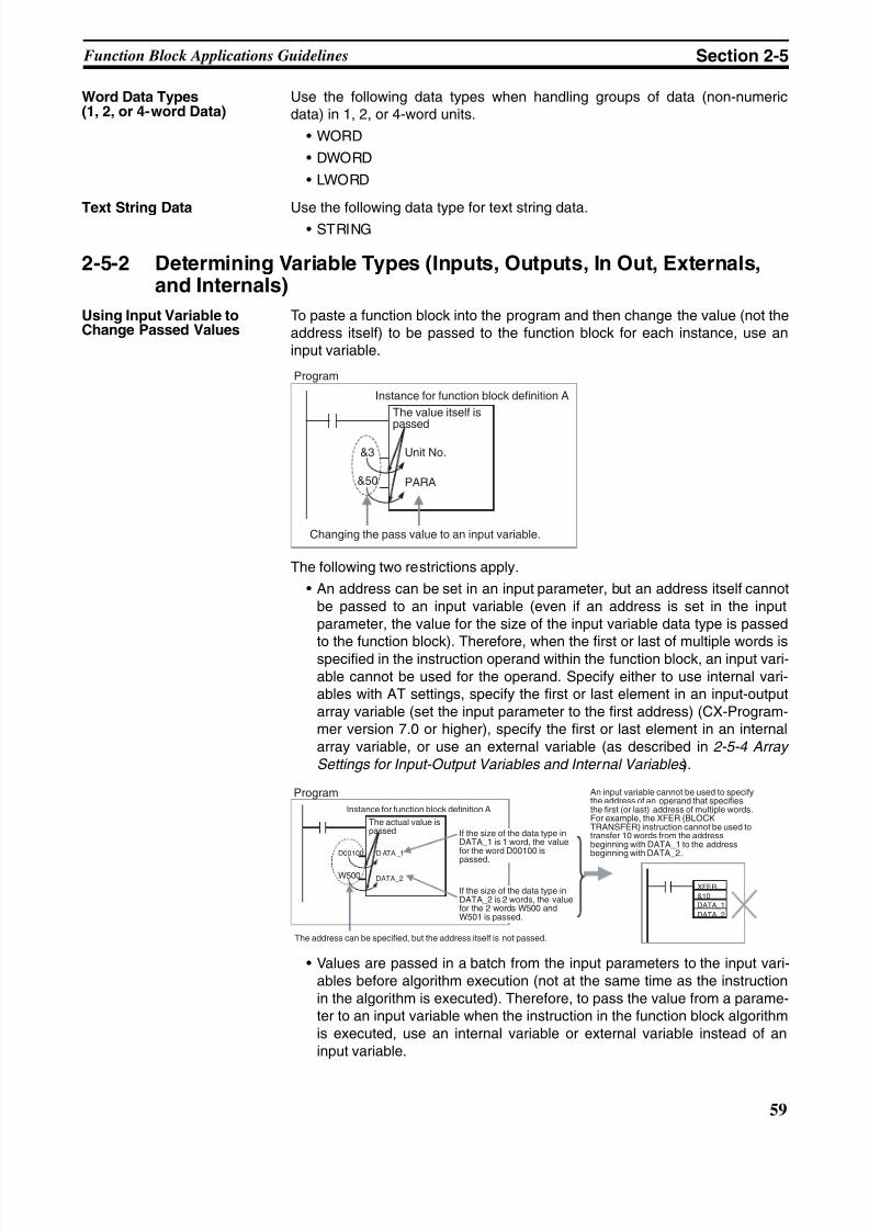
8/11/2019 CX-Programmer V9 Operation Manual FB ST.pdf
http://slidepdf.com/reader/full/cx-programmer-v9-operation-manual-fb-stpdf 85/254
59
Function Block Applications Guidelines Section 2-5
Word Data Types(1, 2, or 4-word Data)
Use the following data types when handling groups of data (non-numericdata) in 1, 2, or 4-word units.
• WORD
• DWORD
• LWORD
Text String Data Use the following data type for text string data.• STRING
2-5-2 Determining Variable Types (Inputs, Outputs, In Out, Externals,and Internals)
Using Input Variable toChange Passed Values
To paste a function block into the program and then change the value (not theaddress itself) to be passed to the function block for each instance, use aninput variable.
The following two restrictions apply.
• An address can be set in an input parameter, but an address itself cannotbe passed to an input variable (even if an address is set in the inputparameter, the value for the size of the input variable data type is passed
to the function block). Therefore, when the first or last of multiple words isspecified in the instruction operand within the function block, an input vari-able cannot be used for the operand. Specify either to use internal vari-ables with AT settings, specify the first or last element in an input-outputarray variable (set the input parameter to the first address) (CX-Program-mer version 7.0 or higher), specify the first or last element in an internalarray variable, or use an external variable (as described in 2-5-4 Array
Settings for Input-Output Variables and Internal Variables ).
• Values are passed in a batch from the input parameters to the input vari-ables before algorithm execution (not at the same time as the instructionin the algorithm is executed). Therefore, to pass the value from a parame-ter to an input variable when the instruction in the function block algorithmis executed, use an internal variable or external variable instead of aninput variable.
&3 Unit No.
PARA&50
Program
Instance for function block definition A
The value itself ispassed
Changing the pass value to an input variable.
D00100 D ATA _1
W500
XFER
&10
DATA_1 DATA_2
DATA_2
Program
Instance for function block definition A
The actual value ispassed If the size of the data type in
DATA_1 is 1 word, the valuefor the word D00100 is
passed.
If the size of the data type inDATA_2 is 2 words, the valuefor the 2 words W500 andW501 is passed.
An input variable cannot be used to specifythe address of an operand that specifiesthe first (or last) address of multiple words.For example, the XFER (BLOCKTRANSFER) instruction cannot be used totransfer 10 words from the addressbeginning with DATA_1 to the addressbeginning with DATA_2.
The address can be specified, but the address itself is not passed.
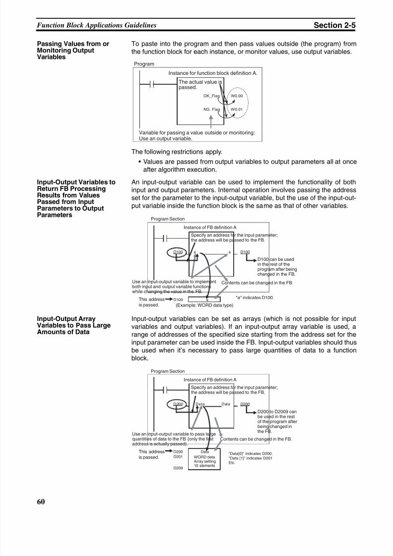
8/11/2019 CX-Programmer V9 Operation Manual FB ST.pdf
http://slidepdf.com/reader/full/cx-programmer-v9-operation-manual-fb-stpdf 86/254
60
Function Block Applications Guidelines Section 2-5
Passing Values from orMonitoring OutputVariables
To paste into the program and then pass values outside (the program) fromthe function block for each instance, or monitor values, use output variables.
The following restrictions apply.
• Values are passed from output variables to output parameters all at onceafter algorithm execution.
Input-Output Variables toReturn FB Processing
Results from ValuesPassed from InputParameters to OutputParameters
An input-output variable can be used to implement the functionality of bothinput and output parameters. Internal operation involves passing the addressset for the parameter to the input-output variable, but the use of the input-out-put variable inside the function block is the same as that of other variables.
Input-Output ArrayVariables to Pass LargeAmounts of Data
Input-output variables can be set as arrays (which is not possible for inputvariables and output variables). If an input-output array variable is used, arange of addresses of the specified size starting from the address set for theinput parameter can be used inside the FB. Input-output variables should thusbe used when it’s necessary to pass large quantities of data to a functionblock.
W0.00OK_Flag
NG_Flag W0.01
Program
Instance for function block definition A.
The actual value ispassed.
Variable for passing a value outside or monitoring:Use an output variable.
D100 a a
D100 a
D100
Program Section
Instance of FB definition A
Specify an address for the input parameter;the address will be passed to the FB.
D100 can be usedin the rest of theprogram after beingchanged in the FB.
Use an input-output variable to implementboth input and output variable functions
while changing the value in the FB.
Contents can be changed in the FB.
This address
is passed. (Example: WORD data type)
"a" indicates D100.
D200 Data Data
D200
D201
D209
Data
D200
Program Section
Instance of FB definition A
Specify an address for the input parameter;the address will be passed to the FB.
D200 to D2009 canbe used in the restof the program afterbeing changed inthe FB.
Use an input-output variable to pass largequantities of data to the FB (only the firstaddress is actually passed).
Contents can be changed in the FB.
This address
is passed. WORD dataArray setting10 elements
"Data[0]" indicates D200."Data [1]" indicates D201Etc.
8/11/2019 CX-Programmer V9 Operation Manual FB ST.pdf
http://slidepdf.com/reader/full/cx-programmer-v9-operation-manual-fb-stpdf 87/254
8/11/2019 CX-Programmer V9 Operation Manual FB ST.pdf
http://slidepdf.com/reader/full/cx-programmer-v9-operation-manual-fb-stpdf 88/254
8/11/2019 CX-Programmer V9 Operation Manual FB ST.pdf
http://slidepdf.com/reader/full/cx-programmer-v9-operation-manual-fb-stpdf 89/254
63
Function Block Applications Guidelines Section 2-5
Handling a Block of Read Data in Multiple Words
The allowed amount of read data must be determined in advance and anarray must be prepared that can handle the maximum amount of data. In thisexample, an array receives the FREAD instruction’s read data (operand D).
• Variable tableInput-output variable or internal variable, data type = WORD, array setting
with 100 elements, variable names = read_data[0] to read_data[99]• Data Settings and Internal Function Block Processing
• Input-output variables:Set the input parameter to the address of the first word in the read data(example: D200).
• Internal variables:
Division Using IntegerArray Variables (Ladder
Programming Only)
A two-element array can be used to store the result from a ladder program’sSIGNED BINARY DIVIDE (/) instruction. The result from the instruction is D
(quotient) and D+1 (remainder). This method can be used to obtain the remain-der from a division operation in ladder programming.
Note When ST language is used, it isn’t necessary to use an array to receive theresult of a division operation. Also, the remainder can’t be calculated directlyin ST language. The remainder must be calculated as follows:Remainder = Dividend − (Divisor × Quotient)
2-5-5 Specifying Addresses Allocated to Special I/O Units
Use Index Registers IR0 to IR15 (indirectly specified constant offset) to spec-ify addresses allocated to Special I/O Units based on the value passed for theunit number as an input parameter within the function block definition as
shown in the following examples.Note For details on using Index Registers in function blocks, refer to 2-5-6 Using
Index Registers .
Examples
Example 1: Specifying the CIO Area within a Function Block (Same for DMArea)
Special I/O Units
Variables: Use the unit number as an input variable, and specifying the firstallocation address as an internal variable with the AT set to CIO 2000.
Programs: Use the following procedure.
1,2,3... 1. Multiply the unit number (input variable) by &10, and create the unit num-ber offset (internal variable, DINT data type).
2. Use the MOVR(560) (MOVE TO REGISTER) instruction to store the real I/ O memory address for the first allocation address (internal variable, AT =CIO 2000) in the Index Register (e.g., IR0).
3. Add the unit number offset to the real I/O memory address within the IndexRegister (e.g., IR0).
Example 2: Specifying the Designated Bit in the CIO Area (e.g., CIO Wordn+a, Bit b)
Programs: Use either of the following methods.
FREAD (omitted ) (omitted ) (omitted ) read_data[0]
FREAD (omitted ) (omitted ) (omitted ) read_data[0]
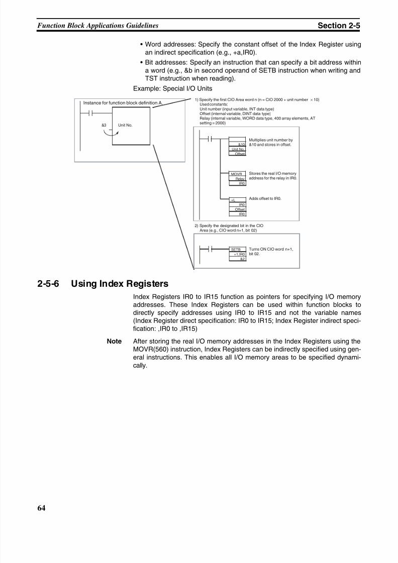
8/11/2019 CX-Programmer V9 Operation Manual FB ST.pdf
http://slidepdf.com/reader/full/cx-programmer-v9-operation-manual-fb-stpdf 90/254
64
Function Block Applications Guidelines Section 2-5
• Word addresses: Specify the constant offset of the Index Register usingan indirect specification (e.g., +a,IR0).
• Bit addresses: Specify an instruction that can specify a bit address withina word (e.g., &b in second operand of SETB instruction when writing andTST instruction when reading).
Example: Special I/O Units
2-5-6 Using Index Registers
Index Registers IR0 to IR15 function as pointers for specifying I/O memoryaddresses. These Index Registers can be used within function blocks todirectly specify addresses using IR0 to IR15 and not the variable names(Index Register direct specification: IR0 to IR15; Index Register indirect speci-fication: ,IR0 to ,IR15)
Note After storing the real I/O memory addresses in the Index Registers using theMOVR(560) instruction, Index Registers can be indirectly specified using gen-eral instructions. This enables all I/O memory areas to be specified dynami-cally.
&3 Unit No.
&10
Unit No.
Offset
MOVR
Relay
IR0
+L
IR0
Offset
IR0
SETB
+1,IR0
&2
Instance for function block definition A.1) Specify the first CIO Area word n (n = CIO 2000 + unit number × 10)
Used constants:Unit number (input variable, INT data type)Offset (internal variable, DINT data type)Relay (internal variable, WORD data type, 400 array elements, ATsetting = 2000)
Multiplies unit number by&10 and stores in offset.
Stores the real I/O memoryaddress for the relay in IR0.
Adds offset to IR0.
2) Specify the designated bit in the CIOArea (e.g., CIO word n+1, bit 02)
Turns ON CIO word n+1,bit 02.
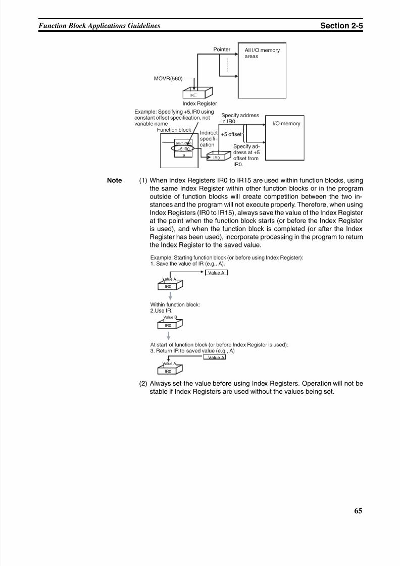
8/11/2019 CX-Programmer V9 Operation Manual FB ST.pdf
http://slidepdf.com/reader/full/cx-programmer-v9-operation-manual-fb-stpdf 91/254
65
Function Block Applications Guidelines Section 2-5
Note (1) When Index Registers IR0 to IR15 are used within function blocks, usingthe same Index Register within other function blocks or in the program
outside of function blocks will create competition between the two in-stances and the program will not execute properly. Therefore, when usingIndex Registers (IR0 to IR15), always save the value of the Index Registerat the point when the function block starts (or before the Index Registeris used), and when the function block is completed (or after the IndexRegister has been used), incorporate processing in the program to returnthe Index Register to the saved value.
(2) Always set the value before using Index Registers. Operation will not bestable if Index Registers are used without the values being set.
IR@
IR0
+5,IR0
a
MOVR(560)
Pointer All I/O memoryareas
Index Register
I/O memory
Example: Specifying +5,IR0 usingconstant offset specification, notvariable name
Function block
Instruction
Indirectspecifi-cation
Specify addressin IR0
+5 offset
Specify ad-dress at +5offset fromIR0.
Value A
IR0
IR0
IR0
Value A
Value A
Value A
Value B
Value A
Example: Starting function block (or before using Index Register):1. Save the value of IR (e.g., A).
Within function block:2.Use IR.
At start of function block (or before Index Register is used):3. Return IR to saved value (e.g., A)
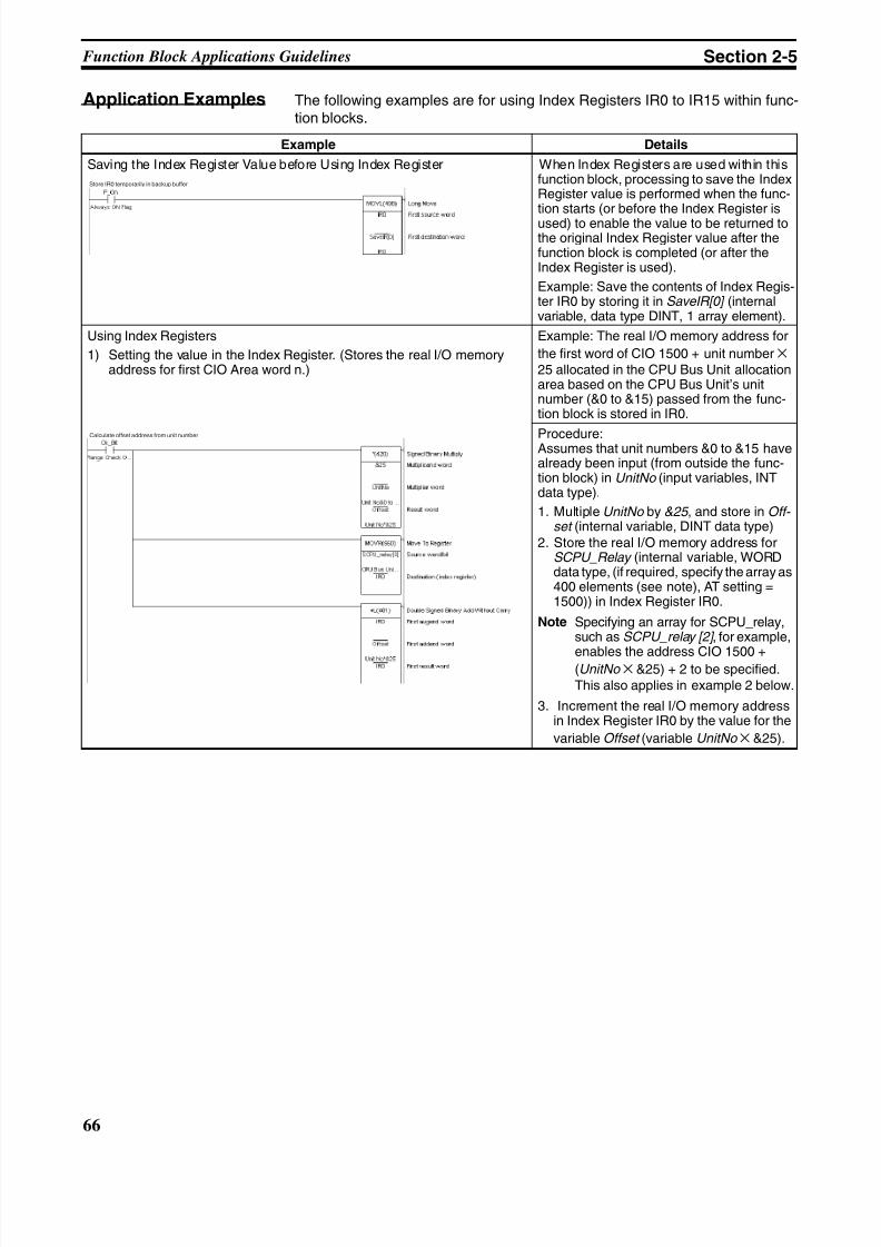
8/11/2019 CX-Programmer V9 Operation Manual FB ST.pdf
http://slidepdf.com/reader/full/cx-programmer-v9-operation-manual-fb-stpdf 92/254
66
Function Block Applications Guidelines Section 2-5
Application Examples The following examples are for using Index Registers IR0 to IR15 within func-tion blocks.
Example Details
Saving the Index Register Value before Using Index Register When Index Registers are used within thisfunction block, processing to save the IndexRegister value is performed when the func-tion starts (or before the Index Register isused) to enable the value to be returned tothe original Index Register value after thefunction block is completed (or after theIndex Register is used).
Example: Save the contents of Index Regis-ter IR0 by storing it in SaveIR[0] (internalvariable, data type DINT, 1 array element).
Using Index Registers
1) Setting the value in the Index Register. (Stores the real I/O memoryaddress for first CIO Area word n.)
Example: The real I/O memory address for
the first word of CIO 1500 + unit number × 25 allocated in the CPU Bus Unit allocationarea based on the CPU Bus Unit’s unitnumber (&0 to &15) passed from the func-tion block is stored in IR0.
Procedure:Assumes that unit numbers &0 to &15 havealready been input (from outside the func-tion block) in UnitNo (input variables, INTdata type).
1. Multiple UnitNo by &25 , and store in Off- set (internal variable, DINT data type)
2. Store the real I/O memory address forSCPU_Relay (internal variable, WORDdata type, (if required, specify the array as400 elements (see note), AT setting =1500)) in Index Register IR0.
Note Specifying an array for SCPU_relay,such as SCPU_relay [2] , for example,
enables the address CIO 1500 +(UnitNo × &25) + 2 to be specified.This also applies in example 2 below.
3. Increment the real I/O memory addressin Index Register IR0 by the value for the
variable Offset (variable UnitNo × &25).
Store IR0 temporarily in backup buffer
Calculate offset address from unit number
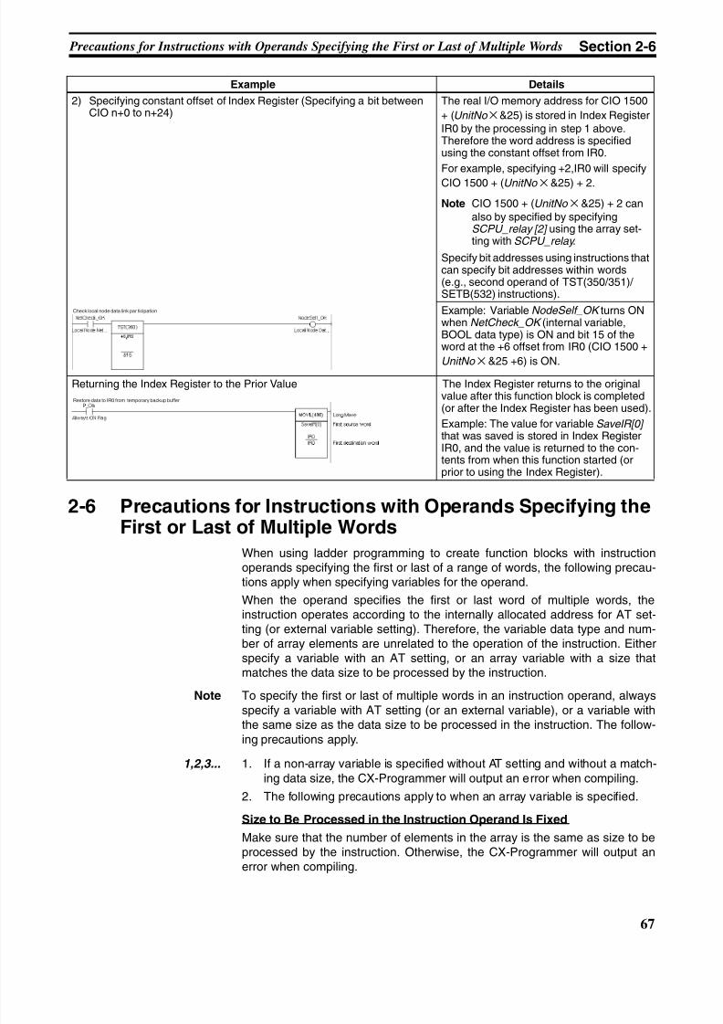
8/11/2019 CX-Programmer V9 Operation Manual FB ST.pdf
http://slidepdf.com/reader/full/cx-programmer-v9-operation-manual-fb-stpdf 93/254
67
Precautions for Instructions with Operands Specifying the First or Last of Multiple Words Section 2-6
2-6 Precautions for Instructions with Operands Specifying theFirst or Last of Multiple Words
When using ladder programming to create function blocks with instructionoperands specifying the first or last of a range of words, the following precau-tions apply when specifying variables for the operand.
When the operand specifies the first or last word of multiple words, theinstruction operates according to the internally allocated address for AT set-ting (or external variable setting). Therefore, the variable data type and num-ber of array elements are unrelated to the operation of the instruction. Eitherspecify a variable with an AT setting, or an array variable with a size thatmatches the data size to be processed by the instruction.
Note To specify the first or last of multiple words in an instruction operand, alwaysspecify a variable with AT setting (or an external variable), or a variable withthe same size as the data size to be processed in the instruction. The follow-ing precautions apply.
1,2,3... 1. If a non-array variable is specified without AT setting and without a match-ing data size, the CX-Programmer will output an error when compiling.
2. The following precautions apply to when an array variable is specified.
Size to Be Processed in the Instruction Operand Is Fixed
Make sure that the number of elements in the array is the same as size to beprocessed by the instruction. Otherwise, the CX-Programmer will output anerror when compiling.
2) Specifying constant offset of Index Register (Specifying a bit betweenCIO n+0 to n+24)
The real I/O memory address for CIO 1500
+ (UnitNo× &25) is stored in Index RegisterIR0 by the processing in step 1 above.Therefore the word address is specifiedusing the constant offset from IR0.
For example, specifying +2,IR0 will specify
CIO 1500 + (UnitNo × &25) + 2.
Note CIO 1500 + (UnitNo × &25) + 2 canalso by specified by specifyingSCPU_relay [2] using the array set-ting with SCPU_relay .
Specify bit addresses using instructions thatcan specify bit addresses within words(e.g., second operand of TST(350/351)/ SETB(532) instructions).
Example: Variable NodeSelf_OK turns ONwhen NetCheck_OK (internal variable,BOOL data type) is ON and bit 15 of theword at the +6 offset from IR0 (CIO 1500 +
UnitNo × &25 +6) is ON.
Returning the Index Register to the Prior Value The Index Register returns to the originalvalue after this function block is completed(or after the Index Register has been used).
Example: The value for variable SaveIR[0] that was saved is stored in Index RegisterIR0, and the value is returned to the con-tents from when this function started (orprior to using the Index Register).
Example Details
Check local node data link par ticipation
Restore data to IR0 from temporary backup buffer
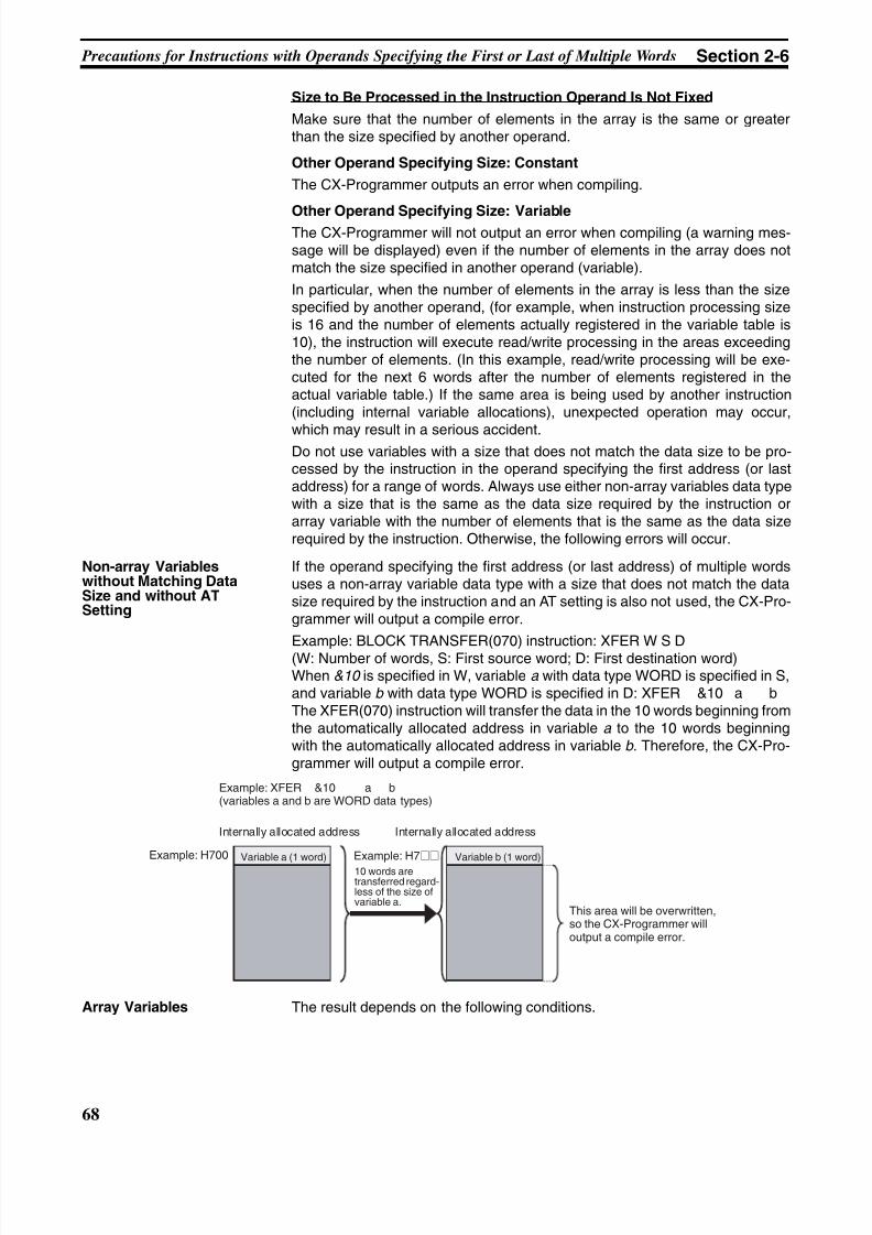
8/11/2019 CX-Programmer V9 Operation Manual FB ST.pdf
http://slidepdf.com/reader/full/cx-programmer-v9-operation-manual-fb-stpdf 94/254
68
Precautions for Instructions with Operands Specifying the First or Last of Multiple Words Section 2-6
Size to Be Processed in the Instruction Operand Is Not Fixed
Make sure that the number of elements in the array is the same or greaterthan the size specified by another operand.
Other Operand Specifying Size: Constant
The CX-Programmer outputs an error when compiling.
Other Operand Specifying Size: VariableThe CX-Programmer will not output an error when compiling (a warning mes-sage will be displayed) even if the number of elements in the array does notmatch the size specified in another operand (variable).
In particular, when the number of elements in the array is less than the sizespecified by another operand, (for example, when instruction processing sizeis 16 and the number of elements actually registered in the variable table is10), the instruction will execute read/write processing in the areas exceedingthe number of elements. (In this example, read/write processing will be exe-cuted for the next 6 words after the number of elements registered in theactual variable table.) If the same area is being used by another instruction(including internal variable allocations), unexpected operation may occur,
which may result in a serious accident.Do not use variables with a size that does not match the data size to be pro-cessed by the instruction in the operand specifying the first address (or lastaddress) for a range of words. Always use either non-array variables data typewith a size that is the same as the data size required by the instruction orarray variable with the number of elements that is the same as the data sizerequired by the instruction. Otherwise, the following errors will occur.
Non-array Variableswithout Matching DataSize and without ATSetting
If the operand specifying the first address (or last address) of multiple wordsuses a non-array variable data type with a size that does not match the datasize required by the instruction and an AT setting is also not used, the CX-Pro-grammer will output a compile error.
Example: BLOCK TRANSFER(070) instruction: XFER W S D(W: Number of words, S: First source word; D: First destination word)When &10 is specified in W, variable a with data type WORD is specified in S,and variable b with data type WORD is specified in D: XFER &10 a bThe XFER(070) instruction will transfer the data in the 10 words beginning fromthe automatically allocated address in variable a to the 10 words beginningwith the automatically allocated address in variable b . Therefore, the CX-Pro-grammer will output a compile error.
Array Variables The result depends on the following conditions.
Example: XFER &10 a b(variables a and b are WORD data types)
Internally allocated address Internally allocated address
Example: H700 Example: H7@@ Variable b (1 word)Variable a (1 word)
10 words aretransferred regard-less of the size ofvariable a.
This area will be overwritten,so the CX-Programmer willoutput a compile error.
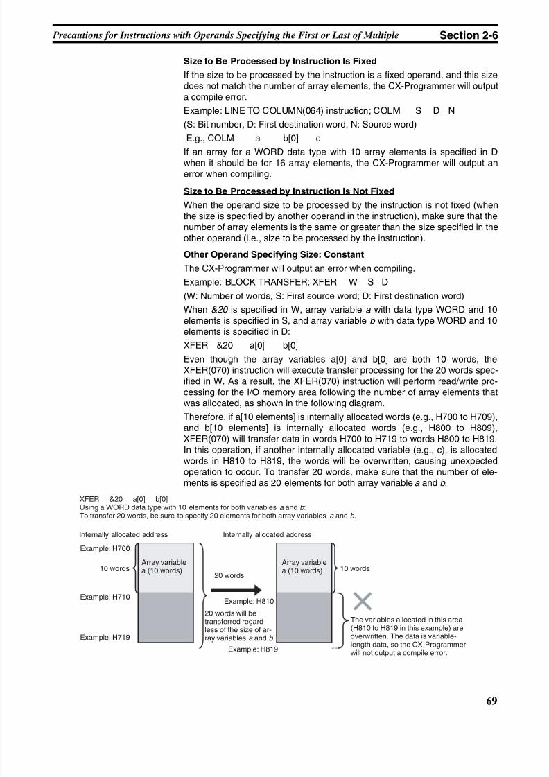
8/11/2019 CX-Programmer V9 Operation Manual FB ST.pdf
http://slidepdf.com/reader/full/cx-programmer-v9-operation-manual-fb-stpdf 95/254
69
Precautions for Instructions with Operands Specifying the First or Last of Multiple Section 2-6
Size to Be Processed by Instruction Is Fixed
If the size to be processed by the instruction is a fixed operand, and this sizedoes not match the number of array elements, the CX-Programmer will outputa compile error.
Example: LINE TO COLUMN(064) instruction; COLM S D N
(S: Bit number, D: First destination word, N: Source word)
E.g., COLM a b[0] c
If an array for a WORD data type with 10 array elements is specified in Dwhen it should be for 16 array elements, the CX-Programmer will output anerror when compiling.
Size to Be Processed by Instruction Is Not Fixed
When the operand size to be processed by the instruction is not fixed (whenthe size is specified by another operand in the instruction), make sure that thenumber of array elements is the same or greater than the size specified in theother operand (i.e., size to be processed by the instruction).
Other Operand Specifying Size: Constant
The CX-Programmer will output an error when compiling.Example: BLOCK TRANSFER: XFER W S D
(W: Number of words, S: First source word; D: First destination word)
When &20 is specified in W, array variable a with data type WORD and 10elements is specified in S, and array variable b with data type WORD and 10elements is specified in D:
XFER &20 a[0] b[0]
Even though the array variables a[0] and b[0] are both 10 words, theXFER(070) instruction will execute transfer processing for the 20 words spec-ified in W. As a result, the XFER(070) instruction will perform read/write pro-cessing for the I/O memory area following the number of array elements thatwas allocated, as shown in the following diagram.
Therefore, if a[10 elements] is internally allocated words (e.g., H700 to H709),and b[10 elements] is internally allocated words (e.g., H800 to H809),XFER(070) will transfer data in words H700 to H719 to words H800 to H819.In this operation, if another internally allocated variable (e.g., c), is allocatedwords in H810 to H819, the words will be overwritten, causing unexpectedoperation to occur. To transfer 20 words, make sure that the number of ele-ments is specified as 20 elements for both array variable a and b .
XFER &20 a[0] b[0]Using a WORD data type with 10 elements for both variables a and b :To transfer 20 words, be sure to specify 20 elements for both array variables a and b .
Internally allocated address Internally allocated address
Example: H700
10 words
Example: H710
Example: H719
Array variablea (10 words)
20 words
Example: H810
20 words will betransferred regard-less of the size of ar-ray variables a and b .
Example: H819
10 wordsArray variablea (10 words)
The variables allocated in this area(H810 to H819 in this example) areoverwritten. The data is variable-length data, so the CX-Programmerwill not output a compile error.
8/11/2019 CX-Programmer V9 Operation Manual FB ST.pdf
http://slidepdf.com/reader/full/cx-programmer-v9-operation-manual-fb-stpdf 96/254
70
Instruction Support and Operand Restrictions Section 2-7
Other Operand Specifying Size: Variable
Even if the number of array elements does not match the size (i.e., size to beprocessed by the instruction) specified in another operand (variable), the CX-Programmer will not output an error when compiling. The instruction will beexecuted according to the size specified by the operand, regardless of thenumber of elements in the array variable.
Particularly if the number of elements in the array is less than the size (i.e.,size to be processed by the instruction) specified by another operand (vari-able), other variables will be affected and unexpected operation may occur.
2-7 Instruction Support and Operand Restrictions
Instruction Support Refer to the instruction help of the CX-Programmer or the command referencemanual of your PLC for whether or not each instruction of the CS/CJ/NSJ-series CPU Units, CP-series CPU Units, and FQM1-series Units can be used.
Restrictions on Operands • When you use any instruction that has operands specifying the first or lastof multiple words, be sure to read the Section 2-6 Precautions for Instruc-
tions with Operands Specifying the First or Last of Multiple Words before
using the instruction.
• When specifying the first or last word of multiple words in an instructionoperand, input parameters cannot be used to pass data to or from vari-ables. Use an AT setting or an input-output or internal variable array set-ting.
• When you use an input-output variable array setting, set the first wordfor the input parameter.
• When you use an internal variable array setting, prepare an array vari-able with the required number of elements, set the array data in thefunction block definition, and then specify the first or last element in thearray variable for the operand.
• Use an AT setting variable for the operands for which an I/O memoryaddress on a remote node in the network must be specified.
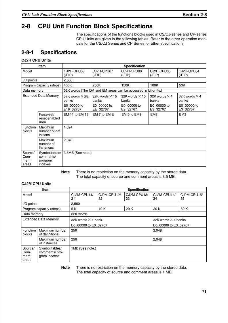
8/11/2019 CX-Programmer V9 Operation Manual FB ST.pdf
http://slidepdf.com/reader/full/cx-programmer-v9-operation-manual-fb-stpdf 97/254
71
CPU Unit Function Block Specifications Section 2-8
2-8 CPU Unit Function Block Specifications
The specifications of the functions blocks used in CS/CJ-series and CP-seriesCPU Units are given in the following tables. Refer to the other operation man-uals for the CS/CJ Series and CP Series for other specifications.
2-8-1 Specifications
CJ2H CPU Units
Note There is no restriction on the memory capacity by the stored data.The total capacity of source and comment areas is 3.5 MB.
CJ2M CPU Units
Note There is no restriction on the memory capacity by the stored data.The total capacity of source and comment areas is 1 MB.
Item Specification
Model CJ2H-CPU68(-EIP)
CJ2H-CPU67(-EIP)
CJ2H-CPU66(-EIP)
CJ2H-CPU65(-EIP)
CJ2H-CPU64(-EIP)
I/O points 2,560
Program capacity (steps) 400K 250K 150K 100K 50K
Data memory 32K words (The DM and EM areas can be accessed in bit-units.)
Extended Data Memory 32K words × 25banks
E0_00000 toE18_32767
32K words × 15banks
E0_00000 toEE_32767
32K words × 10banks
E0_00000 toE9_32767
32K words × 4banks
E0_00000 toE3_32767
32K words × 4banks
E0_00000 toE3_32767
Force-set/ reset enabledarea
EM 11 to EM 18 EM 7 to EM E EM 6 to EM9 EM3 EM3
Functionblocks
Maximumnumber of def-initions
1,024
Maximumnumber ofinstances
2,048
Source/Com-mentareas
Symbol tables/comments/programindexes
3.5MB (See note.)
Item Specification
Model CJ2M-CPU11/ 31
CJ2M-CPU12/ 32
CJ2M-CPU13/ 33
CJ2M-CPU14/ 34
CJ2M-CPU15/ 35
I/O points 2,560
Program capacity (steps) 5 K 10 K 20 K 30 K 60 K
Data memory 32K words
Extended Data Memory 32K words × 1 bank
E0_00000 to E0_32767
32K words × 4 banks
E0_00000 to E3_32767Functionblocks
Maximum numberof definitions
256 2,048
Maximum numberof instances
256 2,048
Source/Com-mentareas
Symbol tables/comments/ pro-gram indexes
1MB (See note.)
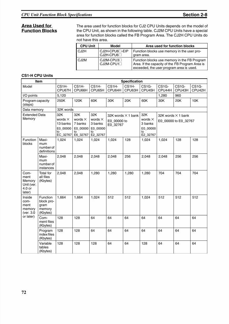
8/11/2019 CX-Programmer V9 Operation Manual FB ST.pdf
http://slidepdf.com/reader/full/cx-programmer-v9-operation-manual-fb-stpdf 98/254
72
CPU Unit Function Block Specifications Section 2-8
Area Used forFunction Blocks
The area used for function blocks for CJ2 CPU Units depends on the model ofthe CPU Unit, as shown in the following table. CJ2M CPU Units have a specialarea for function blocks called the FB Program Area. The CJ2H CPU Units donot have this area.
CS1-H CPU Units
CPU Unit Model Area used for function blocks
CJ2H CJ2H-CPU6@-EIP
CJ2H-CPU6@
Function blocks use memory in the user pro-
gram area.CJ2M CJ2M-CPU3@
CJ2M-CPU1@Function blocks use memory in the FB ProgramArea. If the capacity of the FB Program Area isexceeded, the user program area is used.
Item Specification
Model CS1H-CPU67H
CS1H-CPU66H
CS1H-CPU65H
CS1H-CPU64H
CS1H-CPU63H
CS1G-CPU45H
CS1G-CPU44H
CS1G-CPU43H
CS1G-CPU42H
I/O points 5,120 1,280 960
Program capacity(steps)
250K 120K 60K 30K 20K 60K 30K 20K 10K
Data memory 32K words
Extended DataMemory
32Kwords × 13 banks
E0_00000toEC_32767
32Kwords × 7 banks
E0_00000toE6_32767
32Kwords × 3 banks
E0_00000toE2_32767
32K words × 1 bank
E0_00000 toE0_32767
32Kwords × 3 banks
E0_00000toE2_32767
32K words × 1 bank
E0_00000 to E0_32767
Functionblocks
Maxi-mumnumber ofdefinitions
1,024 1,024 1,024 1,024 128 1,024 1,024 128 128
Maxi-mumnumber ofinstances
2,048 2,048 2,048 2,048 256 2,048 2,048 256 256
Com-mentMemoryUnit (ver.4.0 orlater)
Total forall files(Kbytes)
2,048 2,048 1,280 1,280 1,280 1,280 704 704 704
Insidecom-mentmemory(ver. 3.0or later)
Functionblock pro-grammemory(Kbytes)
1,664 1,664 1,024 512 512 1,024 512 512 512
Com-ment files
(Kbytes)
128 128 64 64 64 64 64 64 64
Programindex files(Kbytes)
128 128 64 64 64 64 64 64 64
Variabletables(Kbytes)
128 128 128 64 64 128 64 64 64
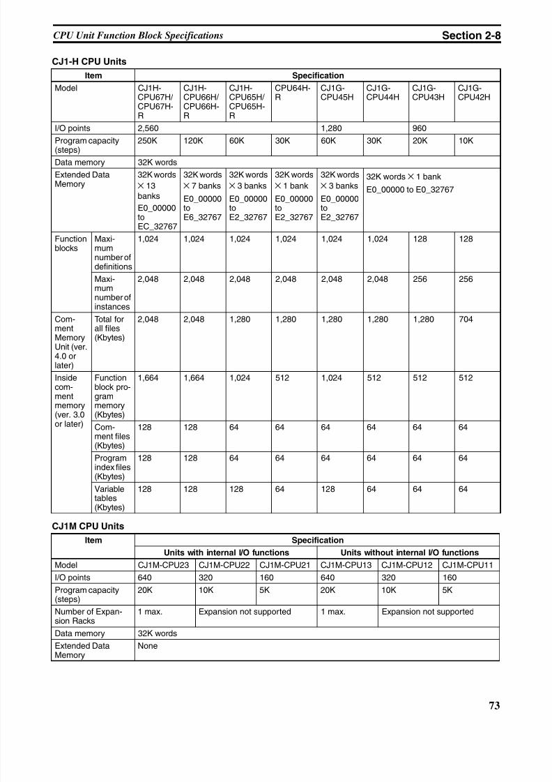
8/11/2019 CX-Programmer V9 Operation Manual FB ST.pdf
http://slidepdf.com/reader/full/cx-programmer-v9-operation-manual-fb-stpdf 99/254
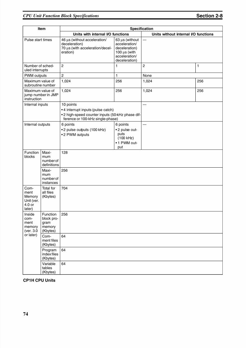
8/11/2019 CX-Programmer V9 Operation Manual FB ST.pdf
http://slidepdf.com/reader/full/cx-programmer-v9-operation-manual-fb-stpdf 100/254
74
CPU Unit Function Block Specifications Section 2-8
CP1H CPU Units
Pulse start times 46 µs (without acceleration/ deceleration)70 µs (with acceleration/decel-eration)
63 µs (withoutacceleration/ deceleration)100 µs (withacceleration/
deceleration)
---
Number of sched-uled interrupts
2 1 2 1
PWM outputs 2 1 None
Maximum value ofsubroutine number
1,024 256 1,024 256
Maximum value of jump number in JMPinstruction
1,024 256 1,024 256
Internal inputs 10 points
• 4 interrupt inputs (pulse catch)
• 2 high-speed counter inputs (50-kHz phase dif-ference or 100-kHz single-phase)
---
Internal outputs 6 points
• 2 pulse outputs (100 kHz)
• 2 PWM outputs
6 points
• 2 pulse out-puts(100 kHz)
• 1 PWM out-put
---
Functionblocks
Maxi-mumnumber ofdefinitions
128
Maxi-mumnumber of
instances
256
Com-mentMemoryUnit (ver.4.0 orlater)
Total forall files(Kbytes)
704
Insidecom-mentmemory(ver. 3.0or later)
Functionblock pro-grammemory(Kbytes)
256
Com-ment files
(Kbytes)
64
Programindex files(Kbytes)
64
Variabletables(Kbytes)
64
Item Specification
Units with internal I/O functions Units without internal I/O functions
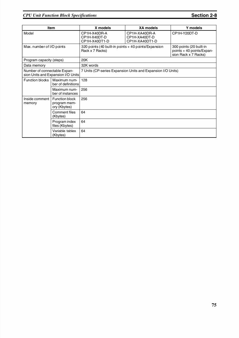
8/11/2019 CX-Programmer V9 Operation Manual FB ST.pdf
http://slidepdf.com/reader/full/cx-programmer-v9-operation-manual-fb-stpdf 101/254
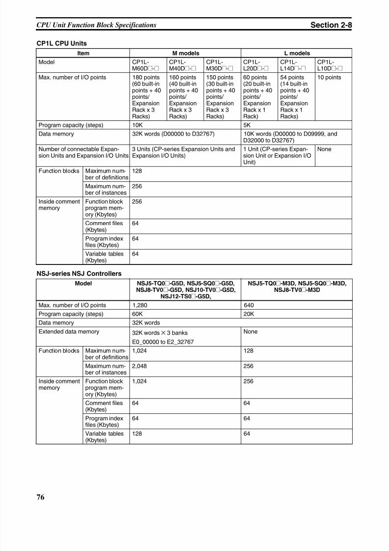
8/11/2019 CX-Programmer V9 Operation Manual FB ST.pdf
http://slidepdf.com/reader/full/cx-programmer-v9-operation-manual-fb-stpdf 102/254
76
CPU Unit Function Block Specifications Section 2-8
CP1L CPU Units
NSJ-series NSJ Controllers
Item M models L models
Model CP1L-M60D@-@
CP1L-M40D@-@
CP1L-M30D@-@
CP1L-L20D@-@
CP1L-L14D@-@
CP1L-L10D@-@
Max. number of I/O points 180 points(60 built-inpoints + 40
points/ ExpansionRack x 3Racks)
160 points(40 built-inpoints + 40
points/ ExpansionRack x 3Racks)
150 points(30 built-inpoints + 40
points/ ExpansionRack x 3Racks)
60 points(20 built-inpoints + 40
points/ ExpansionRack x 1Rack)
54 points(14 built-inpoints + 40
points/ ExpansionRack x 1Racks)
10 points
Program capacity (steps) 10K 5K
Data memory 32K words (D00000 to D32767) 10K words (D00000 to D09999, andD32000 to D32767)
Number of connectable Expan-sion Units and Expansion I/O Units
3 Units (CP-series Expansion Units andExpansion I/O Units)
1 Unit (CP-series Expan-sion Unit or Expansion I/OUnit)
None
Function blocks Maximum num-ber of definitions
128
Maximum num-
ber of instances
256
Inside commentmemory
Function blockprogram mem-ory (Kbytes)
256
Comment files(Kbytes)
64
Program indexfiles (Kbytes)
64
Variable tables(Kbytes)
64
Model NSJ5-TQ0@-G5D, NSJ5-SQ0@-G5D,
NSJ8-TV0@-G5D, NSJ10-TV0@-G5D,NSJ12-TS0@-G5D,
NSJ5-TQ0@-M3D, NSJ5-SQ0@-M3D,
NSJ8-TV0@-M3D
Max. number of I/O points 1,280 640
Program capacity (steps) 60K 20K
Data memory 32K words
Extended data memory 32K words × 3 banks
E0_00000 to E2_32767
None
Function blocks Maximum num-ber of definitions
1,024 128
Maximum num-ber of instances
2,048 256
Inside comment
memory
Function block
program mem-ory (Kbytes)
1,024 256
Comment files(Kbytes)
64 64
Program indexfiles (Kbytes)
64 64
Variable tables(Kbytes)
128 64
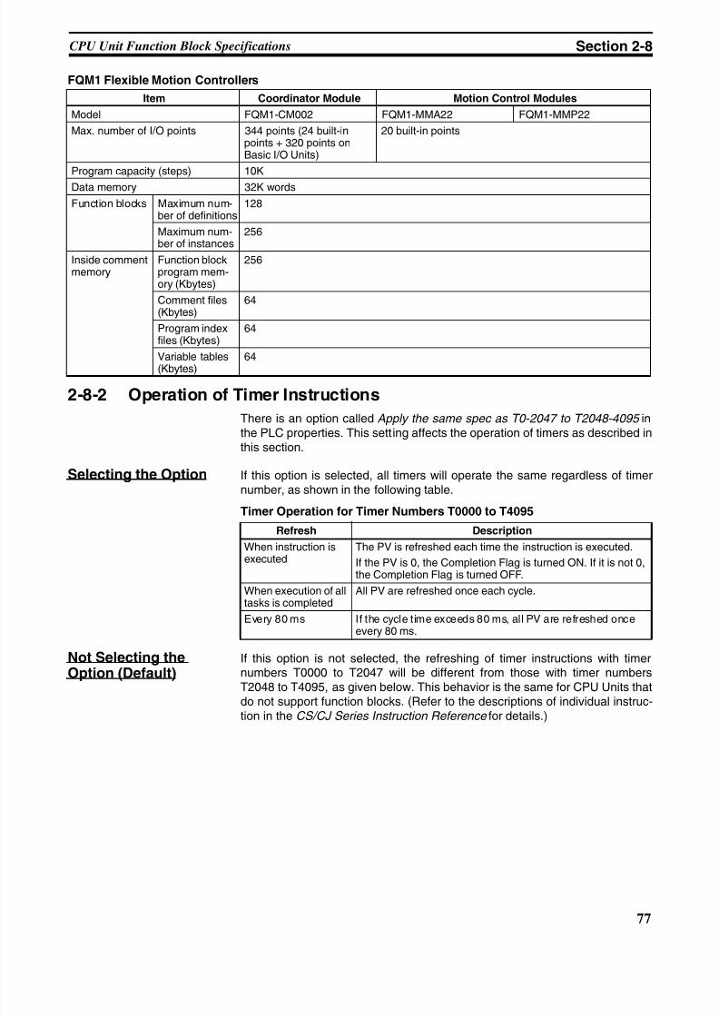
8/11/2019 CX-Programmer V9 Operation Manual FB ST.pdf
http://slidepdf.com/reader/full/cx-programmer-v9-operation-manual-fb-stpdf 103/254
77
CPU Unit Function Block Specifications Section 2-8
FQM1 Flexible Motion Controllers
2-8-2 Operation of Timer Instructions
There is an option called Apply the same spec as T0-2047 to T2048-4095 inthe PLC properties. This setting affects the operation of timers as described inthis section.
Selecting the Option If this option is selected, all timers will operate the same regardless of timernumber, as shown in the following table.
Timer Operation for Timer Numbers T0000 to T4095
Not Selecting theOption (Default)
If this option is not selected, the refreshing of timer instructions with timernumbers T0000 to T2047 will be different from those with timer numbersT2048 to T4095, as given below. This behavior is the same for CPU Units thatdo not support function blocks. (Refer to the descriptions of individual instruc-
tion in the CS/CJ Series Instruction Reference for details.)
Item Coordinator Module Motion Control Modules
Model FQM1-CM002 FQM1-MMA22 FQM1-MMP22
Max. number of I/O points 344 points (24 built-inpoints + 320 points onBasic I/O Units)
20 built-in points
Program capacity (steps) 10K
Data memory 32K words
Function blocks Maximum num-ber of definitions
128
Maximum num-ber of instances
256
Inside commentmemory
Function blockprogram mem-ory (Kbytes)
256
Comment files(Kbytes)
64
Program indexfiles (Kbytes)
64
Variable tables(Kbytes)
64
Refresh DescriptionWhen instruction isexecuted
The PV is refreshed each time the instruction is executed.
If the PV is 0, the Completion Flag is turned ON. If it is not 0,the Completion Flag is turned OFF.
When execution of alltasks is completed
All PV are refreshed once each cycle.
Every 80 ms If the cycle time exceeds 80 ms, all PV are refreshed onceevery 80 ms.

8/11/2019 CX-Programmer V9 Operation Manual FB ST.pdf
http://slidepdf.com/reader/full/cx-programmer-v9-operation-manual-fb-stpdf 104/254
78
Number of Function Block Program Steps and Instance Execution Time Section 2-9
Timer Operation for Timer Numbers T0000 to T2047
Timer Operation for Timer Numbers T2048 to T4095
Select the Apply the same spec as TO-2047 to T2048-4095 Option to ensureconsistent operation when using the timer numbers allocated by default tofunction block variables (T3072 to T4095).
2-9 Number of Function Block Program Steps and InstanceExecution Time
2-9-1 Number of Function Block Program Steps
Number of StepsUsed for FunctionBlocks
When function blocks are used, program memory (steps) is used for the fol-lowing two items.
1. Function block definitions
2. Instances of function block definitions created in programs
Therefore, the more instances of function block definitions that you create, themore memory (steps) will be used.
Guide for Number ofProgram Steps WhenUsing FunctionBlocks
This section applies only to CP-series CPU Units with unit version Ver. 1.0 orlater and CS/CJ-series CPU Units with unit version Ver. 3.0 or later, NSJ Con-trollers, and FQM1 Flexible Motion Controllers.
Use the following equation to calculate the approximate number of programsteps when function block definitions have been created and the instancescopied into the user program of the CPU Unit.
Note The number of instruction steps in the function block definition (p) will not bediminished in subsequence instances when the same function block definitionis copied to multiple locations (i.e., for multiple instances). Therefore, in theabove equation, the number of instances is not multiplied by the number ofinstruction steps in the function block definition (p).
Refresh Description
When instruction isexecuted
The PV is refreshed each time the instruction is executed.
If the PV is 0, the Completion Flag is turned ON. If it is not 0,the Completion Flag is turned OFF.
When execution of alltasks is completed
All PV are refreshed once each cycle.
Every 80 ms If the cycle time exceeds 80 ms, all PV are refreshed onceevery 80 ms.
Refresh Description
When instruction isexecuted
The PV is refreshed each time the instruction is executed.
If the PV is 0, the Completion Flag is turned ON. If it is not 0,the Completion Flag is turned OFF
When execution of alltasks is completed
PV are not updated.
Every 80 ms PV are not updated even if the cycle time exceeds 80 ms.
Number of steps= Number of instances × (Call part size m + I/O parameter transfer part size n × Num-ber of parameters) + Number of instruction steps in the function block definition p(See note.)
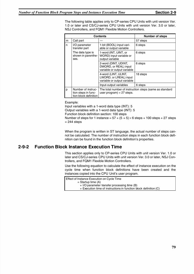
8/11/2019 CX-Programmer V9 Operation Manual FB ST.pdf
http://slidepdf.com/reader/full/cx-programmer-v9-operation-manual-fb-stpdf 105/254
79
Number of Function Block Program Steps and Instance Execution Time Section 2-9
The following table applies only to CP-series CPU Units with unit version Ver.1.0 or later and CS/CJ-series CPU Units with unit version Ver. 3.0 or later,NSJ Controllers, and FQM1 Flexible Motion Controllers.
Example:Input variables with a 1-word data type (INT): 5Output variables with a 1-word data type (INT): 5Function block definition section: 100 stepsNumber of steps for 1 instance = 57 + (5 + 5) × 6 steps + 100 steps + 27 steps= 244 steps
When the program is written in ST language, the actual number of steps can-not be calculated. The number of instruction steps in each function block defi-nition can be found in the function block definition’s properties.
2-9-2 Function Block Instance Execution Time
This section applies only to CP-series CPU Units with unit version Ver. 1.0 orlater and CS/CJ-series CPU Units with unit version Ver. 3.0 or later, NSJ Con-trollers, and FQM1 Flexible Motion Controllers.
Use the following equation to calculate the effect of instance execution on thecycle time when function block definitions have been created and theinstances copied into the CPU Unit’s user program.
Contents Number of steps
m Call part --- 57 steps
n I/O parameter
transfer partThe data type isshown in parenthe-ses.
1-bit (BOOL) input vari-
able or output variable
6 steps
1-word (INT, UINT, orWORD) input variable oroutput variable
6 steps
2-word (DINT, UDINT,DWORD, or REAL) inputvariable or output variable
6 steps
4-word (LINT, ULINT,LWORD, or LREAL) inputvariable or output variable
18 steps
Input-output variables 6 steps
p Number of instruc-tion steps in func-
tion block definition
The total number of instruction steps (same as standarduser program) + 27 steps.
Effect of Instance Execution on Cycle Time= Startup time (A) + I/O parameter transfer processing time (B) + Execution time of instructions in function block definition (C)
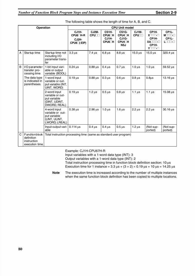
8/11/2019 CX-Programmer V9 Operation Manual FB ST.pdf
http://slidepdf.com/reader/full/cx-programmer-v9-operation-manual-fb-stpdf 106/254
80
Number of Function Block Program Steps and Instance Execution Time Section 2-9
The following table shows the length of time for A, B, and C.
Example: CJ1H-CPU67H-RInput variables with a 1-word data type (INT): 3Output variables with a 1-word data type (INT): 2Total instruction processing time in function block definition section: 10 µsExecution time for 1 instance = 3.3 µs + (3 + 2) × 0.19 µs + 10 µs = 14.25 µs
Note The execution time is increased according to the number of multiple instanceswhen the same function block definition has been copied to multiple locations.
Operation CPU Unit model
CJ1H-CPU6@H-R
CJ2H-CPU6@(-EIP)
CJ2M-CPU@@
CS1H-CPU6@H
CJ1H-CPU6@H
CS1G-CPU4@H
CJ1G-CPU4@H
NSJ
CJ1M-CPU@@
CP1H-X@@@-@
CP1H-XA@@@-@
CP1H-
Y@@@-@
CP1L-M@@@-@
CP1L-L@@@-@
A Startup time Startup time notincluding I/Oparameter trans-fer
3.3 µs 7.4 µs 6.8 µs 8.8 µs 15.0 µs 15.0 µs 320.4 µs
B I/O parametertransfer pro-cessing time
The data typeis indicated inparentheses.
1-bit input vari-able or outputvariable (BOOL)
0.24 µs 0.88 µs 0.4 µs 0.7 µs 1.0 µs 1.0 µs 59.52 µs
1-word inputvariable or out-put variable (INT,UINT, WORD)
0.19 µs 0.88 µs 0.3 µs 0.6 µs 0.8 µs 0.8µs 13.16 µs
2-word input
variable or out-put variable(DINT, UDINT,DWORD, REAL)
0.19 µs 1.2 µs 0.5 µs 0.8 µs 1.1 µs 1.1 µs 15.08 µs
4-word inputvariable or out-put variable(LINT, ULINT,LWORD, LREAL)
0.38 µs 2.96 µs 1.0 µs 1.6 µs 2.2 µs 2.2 µs 30.16 µs
Input-output vari-able
0.114 µs 0.4 µs 0.4 µs 0.5 µs 1.2 µs (Not sup-ported)
(Not sup-ported)
C Function blockdefinitioninstruction
execution time
Total instruction processing time (same as standard user program)
8/11/2019 CX-Programmer V9 Operation Manual FB ST.pdf
http://slidepdf.com/reader/full/cx-programmer-v9-operation-manual-fb-stpdf 107/254
81
SECTION 3Creating Function Blocks
This section describes the procedures for creating function blocks on the CX-Programmer.
3-1 Procedural Flow . . . . . . . . . . . . . . . . . . . . . . . . . . . . . . . . . . . . . . . . . . . . . . . 82
3-2 Procedures. . . . . . . . . . . . . . . . . . . . . . . . . . . . . . . . . . . . . . . . . . . . . . . . . . . . 84
3-2-1 Creating a Project . . . . . . . . . . . . . . . . . . . . . . . . . . . . . . . . . . . . . . . 84
3-2-2 Creating a New Function Block Definition . . . . . . . . . . . . . . . . . . . 84
3-2-3 Defining Function Blocks Created by User . . . . . . . . . . . . . . . . . . . 87
3-2-4 Creating Instances from Function Block Definitions . . . . . . . . . . . . 99
3-2-5 Setting Function Block Parameters Using the Enter Key. . . . . . . . . 101
3-2-6 Setting the FB Instance Areas. . . . . . . . . . . . . . . . . . . . . . . . . . . . . . 104
3-2-7 Checking Internal Address Allocations for Variables . . . . . . . . . . . 106
3-2-8 Copying and Editing Function Block Definitions . . . . . . . . . . . . . . 1083-2-9 Checking the Source Function Block Definition from an Instance . 108
3-2-10 Checking Instance Information such as Nesting Levels. . . . . . . . . . 108
3-2-11 Checking Function Block Usage . . . . . . . . . . . . . . . . . . . . . . . . . . . 109
3-2-12 Compiling Function Block Definitions (Checking Program). . . . . . 110
3-2-13 Printing Function Block Definition . . . . . . . . . . . . . . . . . . . . . . . . . 110
3-2-14 Password Protection of Function Block Definitions. . . . . . . . . . . . . 111
3-2-15 Comparing Function Blocks . . . . . . . . . . . . . . . . . . . . . . . . . . . . . . . 114
3-2-16 Saving and Reusing Function Block Definition Files . . . . . . . . . . . 114
3-2-17 Downloading/Uploading Programs to the Actual CPU Unit . . . . . . 115
3-2-18 Monitoring and Debugging Function Blocks . . . . . . . . . . . . . . . . . . 1163-2-19 Online Editing Function Block Definitions . . . . . . . . . . . . . . . . . . . 124
8/11/2019 CX-Programmer V9 Operation Manual FB ST.pdf
http://slidepdf.com/reader/full/cx-programmer-v9-operation-manual-fb-stpdf 108/254
82
Procedural Flow Section 3-1
3-1 Procedural Flow
The following procedures are used to create function blocks, save them infiles, transfer them to the CPU Unit, monitor them, and debug them.
Creating Function Blocks
Create a Project Refer to 3-2-1 Creating a Project for details.n Creating a New Project
1,2,3... 1. Start the CX-Programmer and select New from the File Menu.
2. Select a Device type : CS1G-H, CS1H-H, CJ1G-H, CJ1H-H, CJ1M, orCP1H, CP1L, NSJ, or FQM1-CM (MMA/MMP).
n Reusing an Existing CX-Programmer Project
1,2,3... 1. Start the CX-Programmer, and read the existing project file (.cxp) createdusing CX-Programmer Ver. 4.0 or earlier by selecting the file from the FileMenu.
2. Select a Device type : CS1H-H, CS1G-H, CJ1G-H, CJ1H-H, CJ1M, or
CP1H, CP1L, NSJ, or FQM1-CM (MMA/MMP).
Create a Function BlockDefinition
Refer to 3-2-2 Creating a New Function Block Definition for details.
1,2,3... 1. Select Function Blocks in the project workspace and right-click.
2. Select Insert Function Block - Ladder or Insert Function Blocks -
Structured Text from the pop-up menu.
Define the Function Block Refer to 3-2-3 Defining Function Blocks Created by User for details.
n Registering Variables before Inputting the Ladder Program or ST Program
1,2,3... 1. Register variables in the variable table.
2. Create the ladder program or ST program.
n Registering Variables as Necessary while Inputting the Ladder Programor ST Program
1,2,3... 1. Create the ladder program or ST program.
2. Register a variable in the variable table whenever required.
Create an Instance fromthe Function BlockDefinition
Refer to 3-2-4 Creating Instances from Function Block Definitions for details.
n Inserting Instances in the Ladder Section Window and then Inputting theInstance Name
1,2,3... 1. Place the cursor at the location at which to create an instance (i.e., a copy)of the function block and press the F Key.
2. Input the name of the instance.
3. Select the function block definition to be copied.
n Registering Instance Names in the Global Symbol Table and thenSelecting the Instance Name when Inserting
1,2,3... 1. Select Function Block as the data type for the variable in the global symboltable.
2. Press the F Key in the Ladder Section Window.
8/11/2019 CX-Programmer V9 Operation Manual FB ST.pdf
http://slidepdf.com/reader/full/cx-programmer-v9-operation-manual-fb-stpdf 109/254
83
Procedural Flow Section 3-1
3. Select the name of the instance that was registered from the pull-downmenu on the FB Instance Field.
Allocate External I/O tothe Function Block
Refer to 3-2-5 Setting Function Block Parameters Using the Enter Key fordetails.
1,2,3... 1. Place the cursor at the position of the input variable or output variable and
press the P Key.2. Input the source address for the input variable or the destination address
for the output variable.
Set the Function BlockMemory Allocations(Instance Areas)
Refer to 3-2-6 Setting the FB Instance Areas for details.
1,2,3... 1. Select the instance and select Function Block/SFC Memory - Function
Block/SFC Memory Allocation from the PLC Menu.
2. Set the function block memory allocations.
Printing, Saving, and Reusing Function Block Files
Compile the FunctionBlock Definition and SaveIt as a Library File
Refer to 3-2-12 Compiling Function Block Definitions (Checking Program) and3-2-16 Saving and Reusing Function Block Definition Files for details.
1,2,3... 1. Compile the function block that has been saved.
2. Print the function block.
3. Save the function block as a function block definition file (.cxf).
4. Read the file into another PLC project.
Transferring the Program to the PLC
Refer to 3-2-17 Downloading/Uploading Programs to the Actual CPU Unit .
Monitoring and Debugging the Function Block Refer to 3-2-18 Monitoring and Debugging Function Blocks .
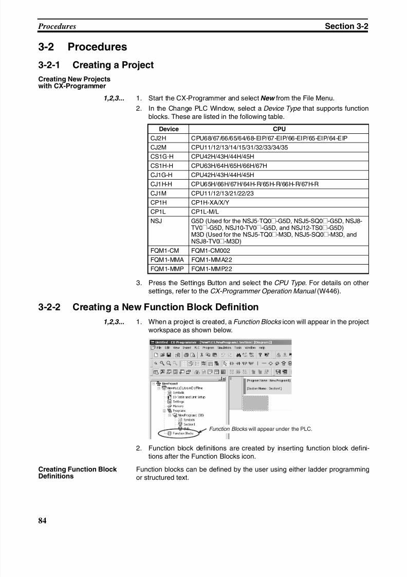
8/11/2019 CX-Programmer V9 Operation Manual FB ST.pdf
http://slidepdf.com/reader/full/cx-programmer-v9-operation-manual-fb-stpdf 110/254
84
Procedures Section 3-2
3-2 Procedures
3-2-1 Creating a Project
Creating New Projectswith CX-Programmer
1,2,3... 1. Start the CX-Programmer and select New from the File Menu.2. In the Change PLC Window, select a Device Type that supports function
blocks. These are listed in the following table.
3. Press the Settings Button and select the CPU Type. For details on othersettings, refer to the CX-Programmer Operation Manual (W446).
3-2-2 Creating a New Function Block Definition
1,2,3... 1. When a project is created, a Function Blocks icon will appear in the projectworkspace as shown below.
2. Function block definitions are created by inserting function block defini-tions after the Function Blocks icon.
Creating Function BlockDefinitions
Function blocks can be defined by the user using either ladder programmingor structured text.
Device CPU
CJ2H CPU68/67/66/65/64/68-EIP/67-EIP/66-EIP/65-EIP/64-EIP
CJ2M CPU11/12/13/14/15/31/32/33/34/35
CS1G-H CPU42H/43H/44H/45H
CS1H-H CPU63H/64H/65H/66H/67H
CJ1G-H CPU42H/43H/44H/45H
CJ1H-H CPU65H/66H/67H/64H-R/65H-R/66H-R/67H-R
CJ1M CPU11/12/13/21/22/23
CP1H CP1H-XA/X/YCP1L CP1L-M/L
NSJ G5D (Used for the NSJ5-TQ0@-G5D, NSJ5-SQ0@-G5D, NSJ8-TV0@-G5D, NSJ10-TV0@-G5D, and NSJ12-TS0@-G5D)M3D (Used for the NSJ5-TQ0@-M3D, NSJ5-SQ0@-M3D, andNSJ8-TV0@-M3D)
FQM1-CM FQM1-CM002
FQM1-MMA FQM1-MMA22
FQM1-MMP FQM1-MMP22
Function Blocks will appear under the PLC.
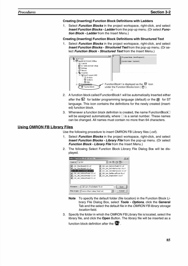
8/11/2019 CX-Programmer V9 Operation Manual FB ST.pdf
http://slidepdf.com/reader/full/cx-programmer-v9-operation-manual-fb-stpdf 111/254
85
Procedures Section 3-2
Creating (Inserting) Function Block Definitions with Ladders
1. Select Function Blocks in the project workspace, right-click, and selectInsert Function Blocks - Ladder from the pop-up menu. (Or select Func- tion Block - Ladder from the Insert Menu.)
Creating (Inserting) Function Block Definitions with Structured Text
1. Select Function Blocks in the project workspace, right-click, and select
Insert Function Blocks - Structured Text from the pop-up menu. (Or se-lect Function Block - Structured Text from the Insert Menu.)
2. A function block called FunctionBlock1 will be automatically inserted either
after the for ladder programming language (default) or the for ST
language. This icon contains the definitions for the newly created (insert-ed) function block.
3. Whenever a function block definition is created, the name FunctionBlock@will be assigned automatically, where @ is a serial number. These namescan be changed. All names must contain no more than 64 characters.
Using OMRON FB Library Files
Use the following procedure to insert OMRON FB Library files (.cxf).
1. Select Function Blocks in the project workspace, right-click, and select
Insert Function Blocks - Library File from the pop-up menu. (Or selectFunction Block - Library File from the Insert Menu.)
2. The following Select Function Block Library File Dialog Box will be dis-played.
Note To specify the default folder (file location) in the Function Block Li-brary File Dialog Box, select Tools - Options , click the General
Tab and the select the default file in the OMRON FB library storage location field.
3. Specify the folder in which the OMRON FB Library file is located, select thelibrary file, and click the Open Button. The library file will be inserted as a
function block definition after the .
FunctionBlock1 is displayed as the Iconunder the Function Blocks Icon ( ).
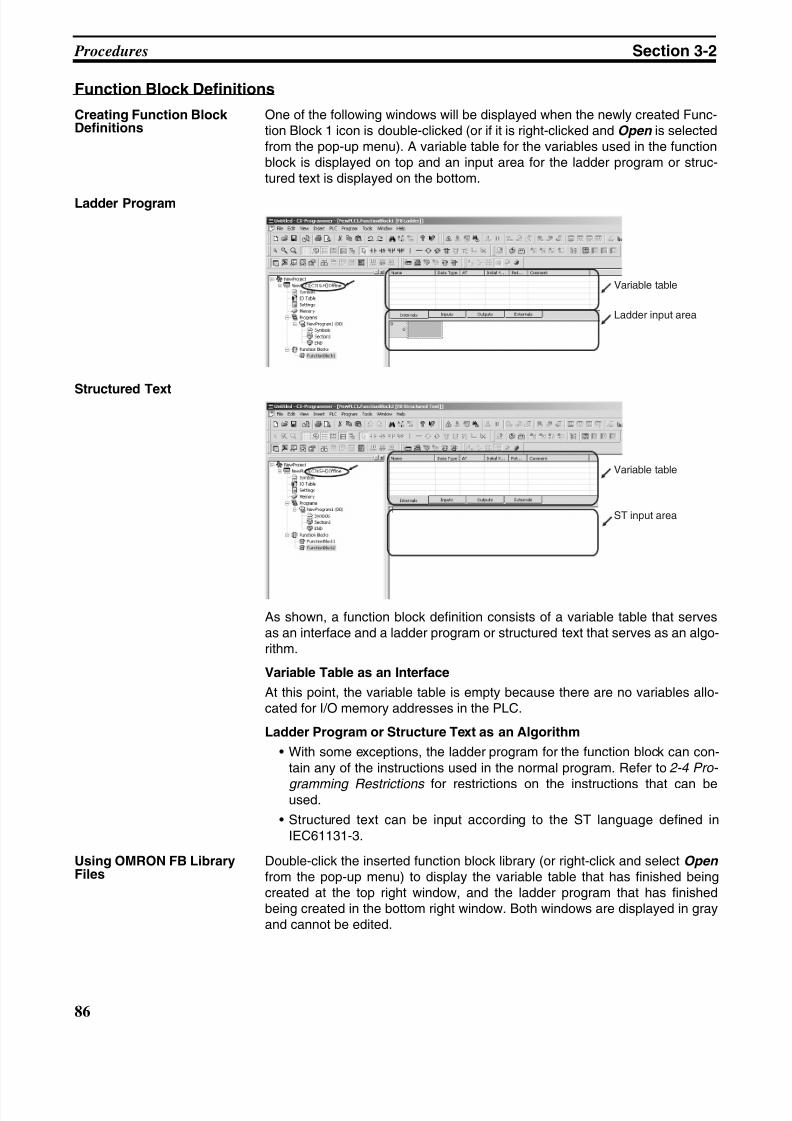
8/11/2019 CX-Programmer V9 Operation Manual FB ST.pdf
http://slidepdf.com/reader/full/cx-programmer-v9-operation-manual-fb-stpdf 112/254
86
Procedures Section 3-2
Function Block Definitions
Creating Function BlockDefinitions
One of the following windows will be displayed when the newly created Func-tion Block 1 icon is double-clicked (or if it is right-clicked and Open is selectedfrom the pop-up menu). A variable table for the variables used in the functionblock is displayed on top and an input area for the ladder program or struc-tured text is displayed on the bottom.
Ladder Program
Structured Text
As shown, a function block definition consists of a variable table that servesas an interface and a ladder program or structured text that serves as an algo-rithm.
Variable Table as an Interface
At this point, the variable table is empty because there are no variables allo-cated for I/O memory addresses in the PLC.
Ladder Program or Structure Text as an Algorithm
• With some exceptions, the ladder program for the function block can con-tain any of the instructions used in the normal program. Refer to 2-4 Pro-
gramming Restrictions for restrictions on the instructions that can beused.
• Structured text can be input according to the ST language defined inIEC61131-3.
Using OMRON FB LibraryFiles
Double-click the inserted function block library (or right-click and select Open from the pop-up menu) to display the variable table that has finished beingcreated at the top right window, and the ladder program that has finishedbeing created in the bottom right window. Both windows are displayed in grayand cannot be edited.
Variable table
Ladder input area
Variable table
ST input area
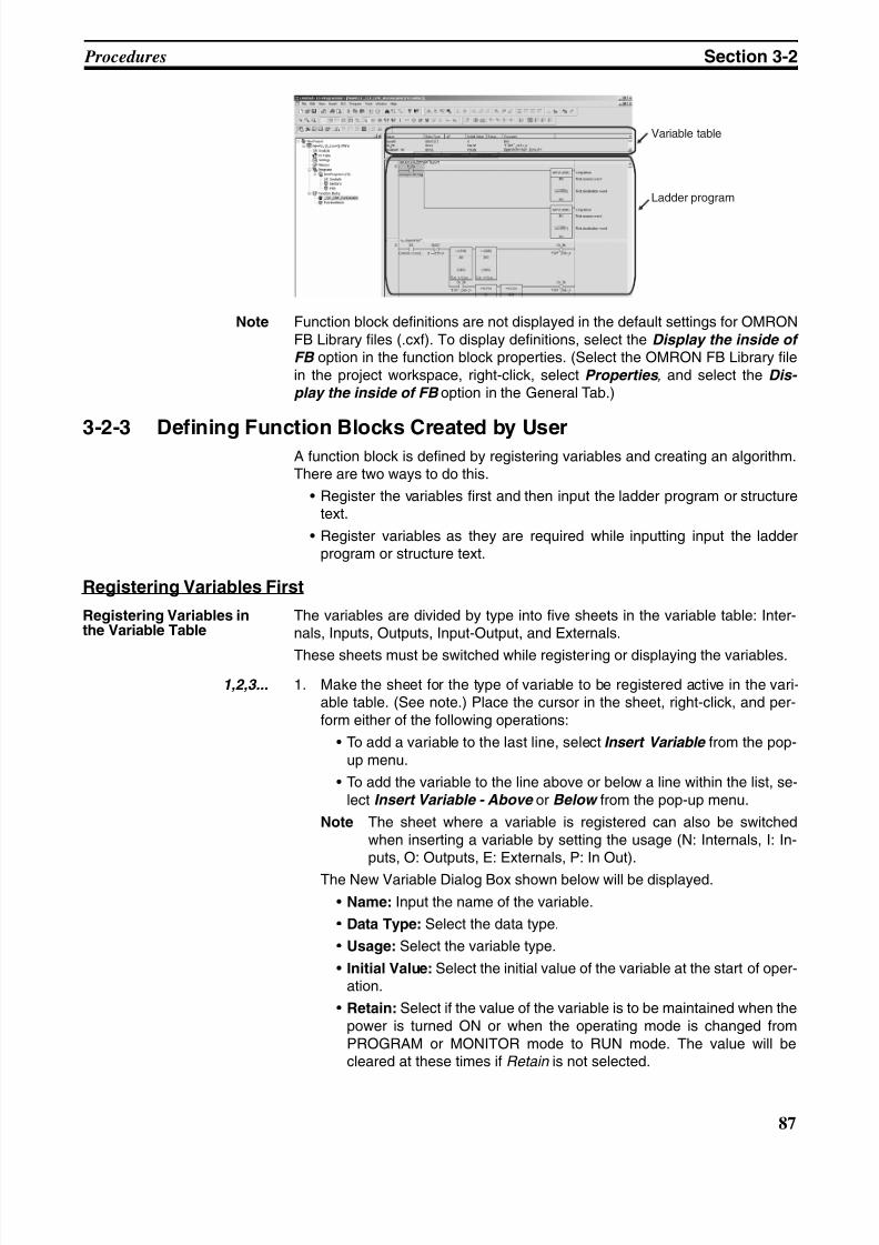
8/11/2019 CX-Programmer V9 Operation Manual FB ST.pdf
http://slidepdf.com/reader/full/cx-programmer-v9-operation-manual-fb-stpdf 113/254
87
Procedures Section 3-2
Note Function block definitions are not displayed in the default settings for OMRONFB Library files (.cxf). To display definitions, select the Display the inside of FB option in the function block properties. (Select the OMRON FB Library filein the project workspace, right-click, select Properties , and select the Dis- play the inside of FB option in the General Tab.)
3-2-3 Defining Function Blocks Created by UserA function block is defined by registering variables and creating an algorithm.There are two ways to do this.
• Register the variables first and then input the ladder program or structuretext.
• Register variables as they are required while inputting input the ladderprogram or structure text.
Registering Variables First
Registering Variables inthe Variable Table
The variables are divided by type into five sheets in the variable table: Inter-nals, Inputs, Outputs, Input-Output, and Externals.
These sheets must be switched while registering or displaying the variables.
1,2,3... 1. Make the sheet for the type of variable to be registered active in the vari-able table. (See note.) Place the cursor in the sheet, right-click, and per-form either of the following operations:
• To add a variable to the last line, select Insert Variable from the pop-up menu.
• To add the variable to the line above or below a line within the list, se-lect Insert Variable - Above or Below from the pop-up menu.
Note The sheet where a variable is registered can also be switchedwhen inserting a variable by setting the usage (N: Internals, I: In-puts, O: Outputs, E: Externals, P: In Out).
The New Variable Dialog Box shown below will be displayed.
• Name: Input the name of the variable.
• Data Type: Select the data type.
• Usage: Select the variable type.
• Initial Value: Select the initial value of the variable at the start of oper-ation.
• Retain: Select if the value of the variable is to be maintained when thepower is turned ON or when the operating mode is changed fromPROGRAM or MONITOR mode to RUN mode. The value will becleared at these times if Retain is not selected.
Variable table
Ladder program
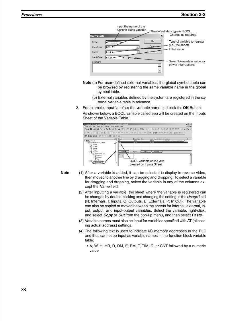
8/11/2019 CX-Programmer V9 Operation Manual FB ST.pdf
http://slidepdf.com/reader/full/cx-programmer-v9-operation-manual-fb-stpdf 114/254
88
Procedures Section 3-2
Note (a) For user-defined external variables, the global symbol table canbe browsed by registering the same variable name in the globalsymbol table.
(b) External variables defined by the system are registered in the ex-ternal variable table in advance.
2. For example, input “aaa” as the variable name and click the OK Button.
As shown below, a BOOL variable called aaa will be created on the InputsSheet of the Variable Table.
Note (1) After a variable is added, it can be selected to display in reverse video,then moved to another line by dragging and dropping. To select a variablefor dragging and dropping, select the variable in any of the columns ex-cept the Name field.
(2) After inputting a variable, the sheet where the variable is registered canbe changed by double-clicking and changing the setting in the Usage field(N: Internals, I: Inputs, O: Outputs, E: Externals, P: In Out). The variablecan also be copied or moved between the sheets for internal, external, in-put, output, and input-output variables. Select the variable, right-click,and select Copy or Cut from the pop-up menu, and then select Paste .
(3) Variable names must also be input for variables specified with AT (allocat-
ing actual address) settings.(4) The following text is used to indicate I/O memory addresses in the PLC
and thus cannot be input as variable names in the function block variabletable.
• A, W, H, HR, D, DM, E, EM, T, TIM, C, or CNT followed by a numericvalue
Input the name of thefunction block variable
The default data type is BOOL.Change as required.
Type of variable to register(i.e., the sheet)
Initial value
Select to maintain value forpower interruptions.
BOOL variable called aaacreated on Inputs Sheet.
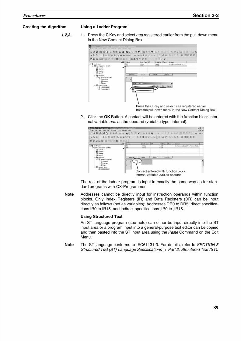
8/11/2019 CX-Programmer V9 Operation Manual FB ST.pdf
http://slidepdf.com/reader/full/cx-programmer-v9-operation-manual-fb-stpdf 115/254
89
Procedures Section 3-2
Creating the Algorithm Using a Ladder Program
1,2,3... 1. Press the C Key and select aaa registered earlier from the pull-down menuin the New Contact Dialog Box.
2. Click the OK Button. A contact will be entered with the function block inter-nal variable aaa as the operand (variable type: internal).
The rest of the ladder program is input in exactly the same way as for stan-dard programs with CX-Programmer.
Note Addresses cannot be directly input for instruction operands within functionblocks. Only Index Registers (IR) and Data Registers (DR) can be inputdirectly as follows (not as variables): Addresses DR0 to DR5, direct specifica-tions IR0 to IR15, and indirect specifications ,IR0 to ,IR15.
Using Structured Text
An ST language program (see note) can either be input directly into the STinput area or a program input into a general-purpose text editor can be copiedand then pasted into the ST input area using the Paste Command on the Edit
Menu.Note The ST language conforms to IEC61131-3. For details, refer to SECTION 5
Structured Text (ST) Language Specifications in Part 2: Structured Text (ST) .
Press the C Key and select aaa registered earlierfrom the pull-down menu in the New Contact Dialog Box.
Contact entered with function blockinternal variable aaa as operand.
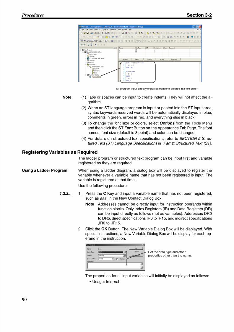
8/11/2019 CX-Programmer V9 Operation Manual FB ST.pdf
http://slidepdf.com/reader/full/cx-programmer-v9-operation-manual-fb-stpdf 116/254
90
Procedures Section 3-2
Note (1) Tabs or spaces can be input to create indents. They will not affect the al-gorithm.
(2) When an ST language program is input or pasted into the ST input area,syntax keywords reserved words will be automatically displayed in blue,
comments in green, errors in red, and everything else in black.
(3) To change the font size or colors, select Options from the Tools Menuand then click the ST Font Button on the Appearance Tab Page. The fontnames, font size (default is 8 point) and color can be changed.
(4) For details on structured text specifications, refer to SECTION 5 Struc-
tured Text (ST) Language Specifications in Part 2: Structured Text (ST) .
Registering Variables as Required
The ladder program or structured text program can be input first and variableregistered as they are required.
Using a Ladder Program When using a ladder diagram, a dialog box will be displayed to register the
variable whenever a variable name that has not been registered is input. Thevariable is registered at that time.
Use the following procedure.
1,2,3... 1. Press the C Key and input a variable name that has not been registered,such as aaa, in the New Contact Dialog Box.
Note Addresses cannot be directly input for instruction operands withinfunction blocks. Only Index Registers (IR) and Data Registers (DR)can be input directly as follows (not as variables): Addresses DR0to DR5, direct specifications IR0 to IR15, and indirect specifications,IR0 to ,IR15.
2. Click the OK Button. The New Variable Dialog Box will be displayed. With
special instructions, a New Variable Dialog Box will be display for each op-erand in the instruction.
The properties for all input variables will initially be displayed as follows:
• Usage: Internal
ST program input directly or pasted from one created in a text editor.
Set the data type and otherproperties other than the name.
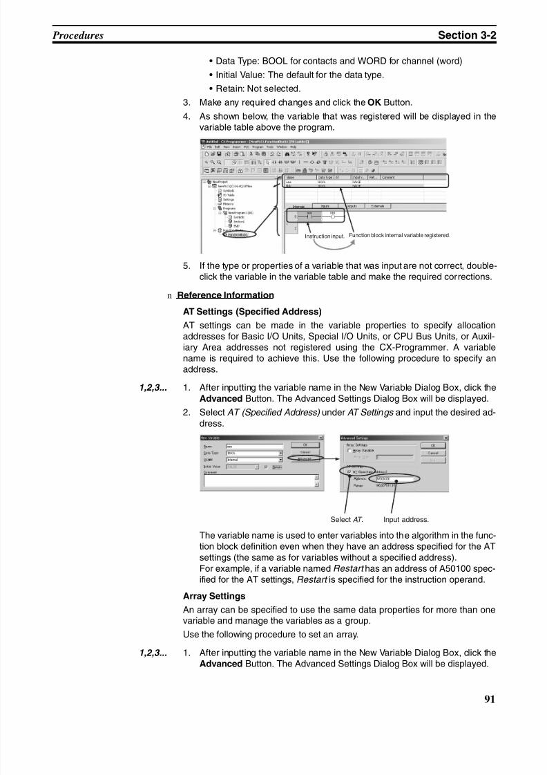
8/11/2019 CX-Programmer V9 Operation Manual FB ST.pdf
http://slidepdf.com/reader/full/cx-programmer-v9-operation-manual-fb-stpdf 117/254
91
Procedures Section 3-2
• Data Type: BOOL for contacts and WORD for channel (word)
• Initial Value: The default for the data type.
• Retain: Not selected.
3. Make any required changes and click the OK Button.
4. As shown below, the variable that was registered will be displayed in thevariable table above the program.
5. If the type or properties of a variable that was input are not correct, double-click the variable in the variable table and make the required corrections.
n Reference Information
AT Settings (Specified Address)
AT settings can be made in the variable properties to specify allocationaddresses for Basic I/O Units, Special I/O Units, or CPU Bus Units, or Auxil-iary Area addresses not registered using the CX-Programmer. A variablename is required to achieve this. Use the following procedure to specify anaddress.
1,2,3... 1. After inputting the variable name in the New Variable Dialog Box, click theAdvanced Button. The Advanced Settings Dialog Box will be displayed.
2. Select AT (Specified Address) under AT Settings and input the desired ad-dress.
The variable name is used to enter variables into the algorithm in the func-
tion block definition even when they have an address specified for the ATsettings (the same as for variables without a specified address).For example, if a variable named Restart has an address of A50100 spec-ified for the AT settings, Restart is specified for the instruction operand.
Array Settings
An array can be specified to use the same data properties for more than onevariable and manage the variables as a group.
Use the following procedure to set an array.
1,2,3... 1. After inputting the variable name in the New Variable Dialog Box, click theAdvanced Button. The Advanced Settings Dialog Box will be displayed.
Instruction input. Function block internal variable registered.
Select AT . Input address.
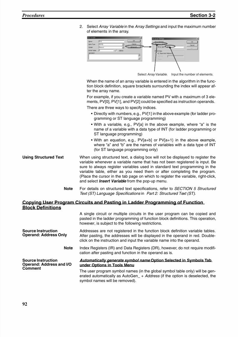
8/11/2019 CX-Programmer V9 Operation Manual FB ST.pdf
http://slidepdf.com/reader/full/cx-programmer-v9-operation-manual-fb-stpdf 118/254
92
Procedures Section 3-2
2. Select Array Variable in the Array Settings and input the maximum numberof elements in the array.
When the name of an array variable is entered in the algorithm in the func-tion block definition, square brackets surrounding the index will appear af-ter the array name.
For example, if you create a variable named PV with a maximum of 3 ele-ments, PV[0], PV[1], and PV[2] could be specified as instruction operands.
There are three ways to specify indices.
• Directly with numbers, e.g., PV[1] in the above example (for ladder pro-
gramming or ST language programming)• With a variable, e.g., PV[a] in the above example, where “a” is the
name of a variable with a data type of INT (for ladder programming orST language programming)
• With an equation, e.g., PV[a+b] or PV[a+1} in the above example,where “a” and “b” are the names of variables with a data type of INT(for ST language programming only)
Using Structured Text When using structured text, a dialog box will not be displayed to register thevariable whenever a variable name that has not been registered is input. Besure to always register variables used in standard text programming in thevariable table, either as you need them or after completing the program.
(Place the cursor in the tab page on which to register the variable, right-click,and select Insert Variable from the pop-up menu.
Note For details on structured text specifications, refer to SECTION 5 Structured
Text (ST) Language Specifications in Part 2: Structured Text (ST) .
Copying User Program Circuits and Pasting in Ladder Programming of FunctionBlock Definitions
A single circuit or multiple circuits in the user program can be copied andpasted in the ladder programming of function block definitions. This operation,however, is subject to the following restrictions.
Source Instruction
Operand: Address Only
Addresses are not registered in the function block definition variable tables.
After pasting, the addresses will be displayed in the operand in red. Double-click on the instruction and input the variable name into the operand.
Note Index Registers (IR) and Data Registers (DR), however, do not require modifi-cation after pasting and function in the operand as is.
Source InstructionOperand: Address and I/OComment
Automatically generate symbol name Option Selected in Symbols Tabunder Options in Tools Menu
The user program symbol names (in the global symbol table only) will be gen-erated automatically as AutoGen_ + Address (if the option is deselected, thesymbol names will be removed).
Select Array Variable. Input the number of elements.
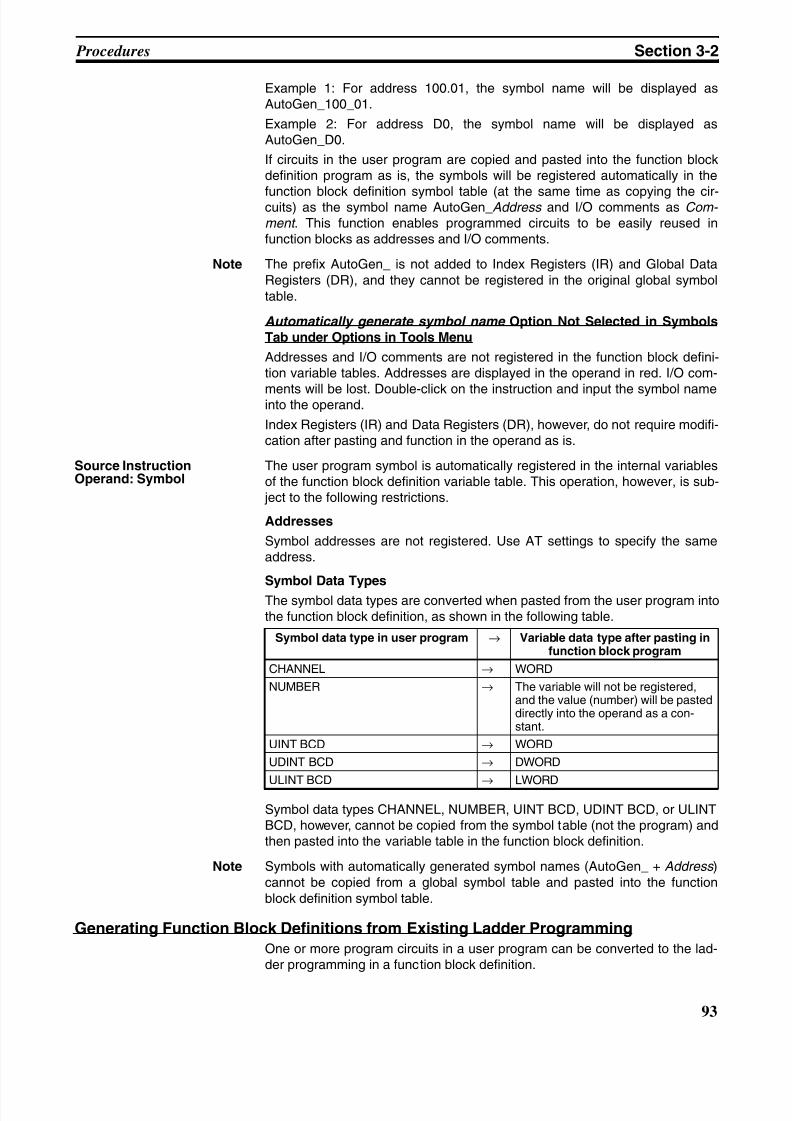
8/11/2019 CX-Programmer V9 Operation Manual FB ST.pdf
http://slidepdf.com/reader/full/cx-programmer-v9-operation-manual-fb-stpdf 119/254
93
Procedures Section 3-2
Example 1: For address 100.01, the symbol name will be displayed asAutoGen_100_01.
Example 2: For address D0, the symbol name will be displayed asAutoGen_D0.
If circuits in the user program are copied and pasted into the function blockdefinition program as is, the symbols will be registered automatically in the
function block definition symbol table (at the same time as copying the cir-cuits) as the symbol name AutoGen_Address and I/O comments as Com- ment . This function enables programmed circuits to be easily reused infunction blocks as addresses and I/O comments.
Note The prefix AutoGen_ is not added to Index Registers (IR) and Global DataRegisters (DR), and they cannot be registered in the original global symboltable.
Automatically generate symbol name Option Not Selected in SymbolsTab under Options in Tools Menu
Addresses and I/O comments are not registered in the function block defini-tion variable tables. Addresses are displayed in the operand in red. I/O com-
ments will be lost. Double-click on the instruction and input the symbol nameinto the operand.
Index Registers (IR) and Data Registers (DR), however, do not require modifi-cation after pasting and function in the operand as is.
Source InstructionOperand: Symbol
The user program symbol is automatically registered in the internal variablesof the function block definition variable table. This operation, however, is sub- ject to the following restrictions.
Addresses
Symbol addresses are not registered. Use AT settings to specify the sameaddress.
Symbol Data Types
The symbol data types are converted when pasted from the user program intothe function block definition, as shown in the following table.
Symbol data types CHANNEL, NUMBER, UINT BCD, UDINT BCD, or ULINTBCD, however, cannot be copied from the symbol table (not the program) andthen pasted into the variable table in the function block definition.
Note Symbols with automatically generated symbol names (AutoGen_ + Address )cannot be copied from a global symbol table and pasted into the functionblock definition symbol table.
Generating Function Block Definitions from Existing Ladder Programming
One or more program circuits in a user program can be converted to the lad-der programming in a function block definition.
Symbol data type in user program → Variable data type after pasting infunction block program
CHANNEL → WORD
NUMBER → The variable will not be registered,and the value (number) will be pasteddirectly into the operand as a con-stant.
UINT BCD → WORD
UDINT BCD → DWORD
ULINT BCD → LWORD
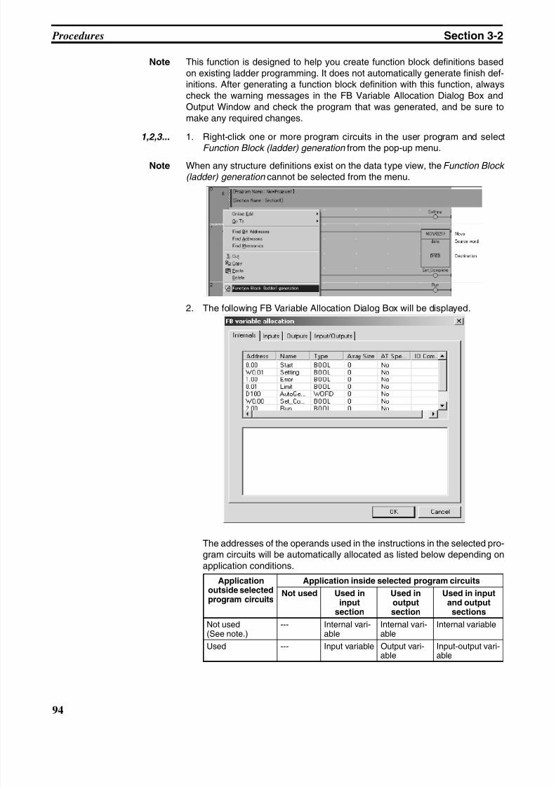
8/11/2019 CX-Programmer V9 Operation Manual FB ST.pdf
http://slidepdf.com/reader/full/cx-programmer-v9-operation-manual-fb-stpdf 120/254
94
Procedures Section 3-2
Note This function is designed to help you create function block definitions basedon existing ladder programming. It does not automatically generate finish def-initions. After generating a function block definition with this function, alwayscheck the warning messages in the FB Variable Allocation Dialog Box andOutput Window and check the program that was generated, and be sure tomake any required changes.
1,2,3... 1. Right-click one or more program circuits in the user program and selectFunction Block (ladder) generation from the pop-up menu.
Note When any structure definitions exist on the data type view, the Function Block (ladder) generation cannot be selected from the menu.
2. The following FB Variable Allocation Dialog Box will be displayed.
The addresses of the operands used in the instructions in the selected pro-
gram circuits will be automatically allocated as listed below depending onapplication conditions.
Applicationoutside selectedprogram circuits
Application inside selected program circuits
Not used Used ininput
section
Used inoutputsection
Used in inputand outputsections
Not used(See note.)
--- Internal vari-able
Internal vari-able
Internal variable
Used --- Input variable Output vari-able
Input-output vari-able
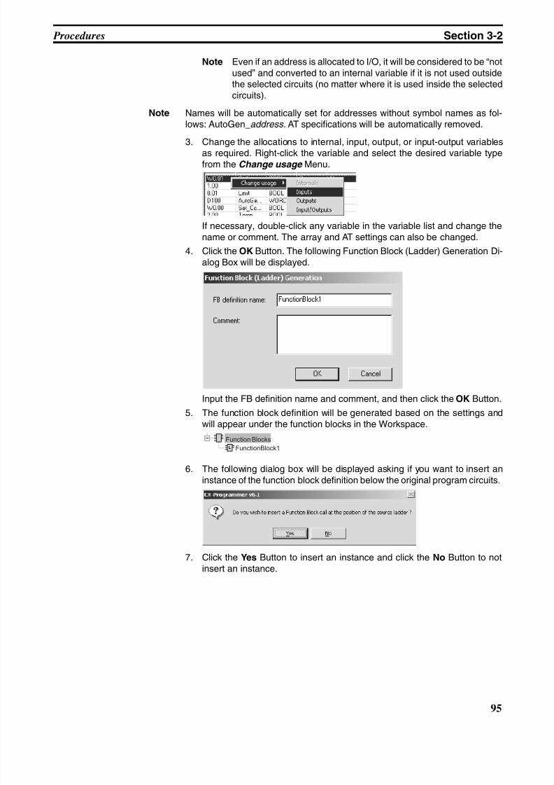
8/11/2019 CX-Programmer V9 Operation Manual FB ST.pdf
http://slidepdf.com/reader/full/cx-programmer-v9-operation-manual-fb-stpdf 121/254
95
Procedures Section 3-2
Note Even if an address is allocated to I/O, it will be considered to be “notused” and converted to an internal variable if it is not used outsidethe selected circuits (no matter where it is used inside the selectedcircuits).
Note Names will be automatically set for addresses without symbol names as fol-lows: AutoGen_address. AT specifications will be automatically removed.
3. Change the allocations to internal, input, output, or input-output variablesas required. Right-click the variable and select the desired variable typefrom the Change usage Menu.
If necessary, double-click any variable in the variable list and change thename or comment. The array and AT settings can also be changed.
4. Click the OK Button. The following Function Block (Ladder) Generation Di-alog Box will be displayed.
Input the FB definition name and comment, and then click the OK Button.
5. The function block definition will be generated based on the settings andwill appear under the function blocks in the Workspace.
6. The following dialog box will be displayed asking if you want to insert aninstance of the function block definition below the original program circuits.
7. Click the Yes Button to insert an instance and click the No Button to notinsert an instance.
Function Blocks
FunctionBlock1
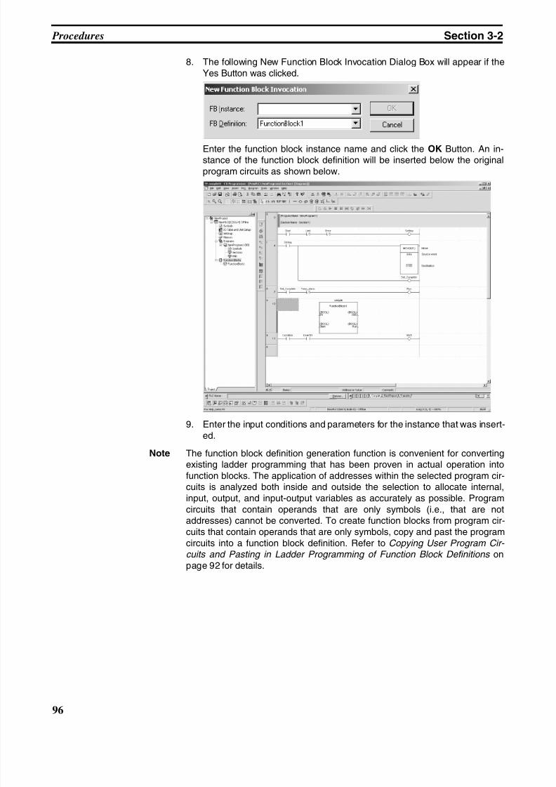
8/11/2019 CX-Programmer V9 Operation Manual FB ST.pdf
http://slidepdf.com/reader/full/cx-programmer-v9-operation-manual-fb-stpdf 122/254
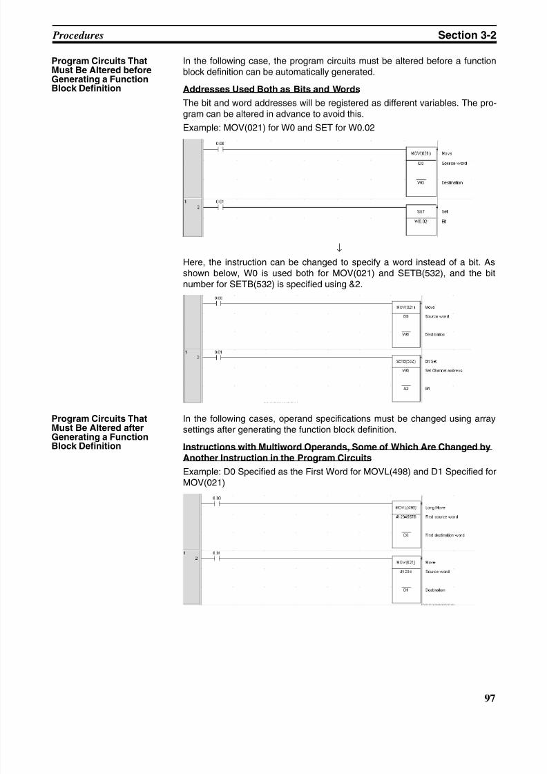
8/11/2019 CX-Programmer V9 Operation Manual FB ST.pdf
http://slidepdf.com/reader/full/cx-programmer-v9-operation-manual-fb-stpdf 123/254
97
Procedures Section 3-2
Program Circuits ThatMust Be Altered beforeGenerating a FunctionBlock Definition
In the following case, the program circuits must be altered before a functionblock definition can be automatically generated.
Addresses Used Both as Bits and Words
The bit and word addresses will be registered as different variables. The pro-gram can be altered in advance to avoid this.
Example: MOV(021) for W0 and SET for W0.02
↓
Here, the instruction can be changed to specify a word instead of a bit. As
shown below, W0 is used both for MOV(021) and SETB(532), and the bitnumber for SETB(532) is specified using &2.
Program Circuits ThatMust Be Altered afterGenerating a FunctionBlock Definition
In the following cases, operand specifications must be changed using arraysettings after generating the function block definition.
Instructions with Multiword Operands, Some of Which Are Changed byAnother Instruction in the Program Circuits
Example: D0 Specified as the First Word for MOVL(498) and D1 Specified forMOV(021)
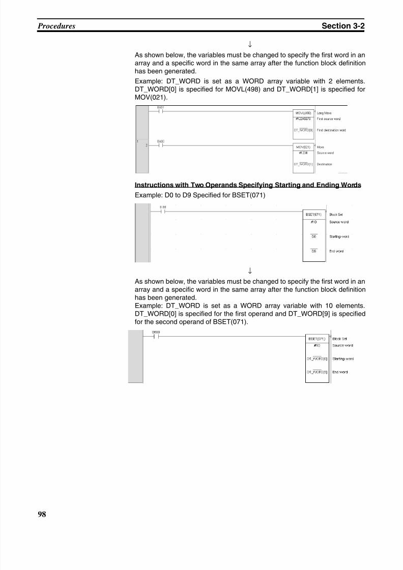
8/11/2019 CX-Programmer V9 Operation Manual FB ST.pdf
http://slidepdf.com/reader/full/cx-programmer-v9-operation-manual-fb-stpdf 124/254
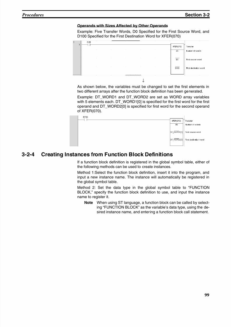
8/11/2019 CX-Programmer V9 Operation Manual FB ST.pdf
http://slidepdf.com/reader/full/cx-programmer-v9-operation-manual-fb-stpdf 125/254
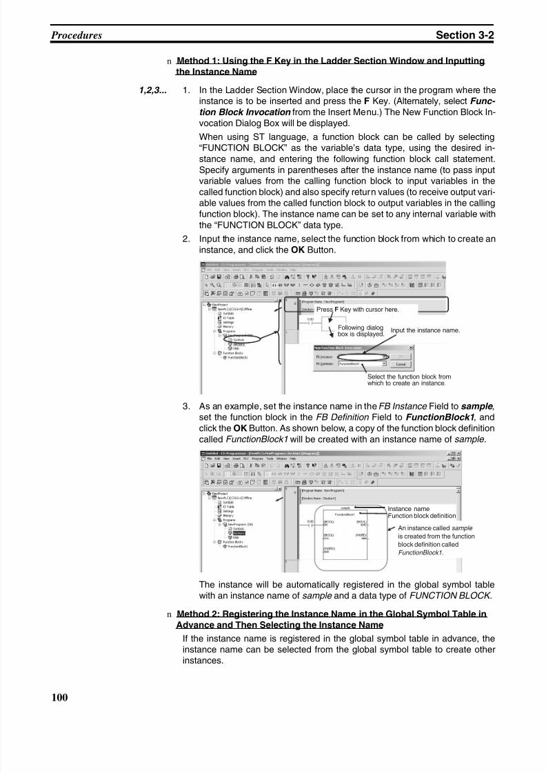
8/11/2019 CX-Programmer V9 Operation Manual FB ST.pdf
http://slidepdf.com/reader/full/cx-programmer-v9-operation-manual-fb-stpdf 126/254
100
Procedures Section 3-2
n Method 1: Using the F Key in the Ladder Section Window and Inputtingthe Instance Name
1,2,3... 1. In the Ladder Section Window, place the cursor in the program where theinstance is to be inserted and press the F Key. (Alternately, select Func-
tion Block Invocation from the Insert Menu.) The New Function Block In-vocation Dialog Box will be displayed.
When using ST language, a function block can be called by selecting“FUNCTION BLOCK” as the variable’s data type, using the desired in-stance name, and entering the following function block call statement.Specify arguments in parentheses after the instance name (to pass inputvariable values from the calling function block to input variables in thecalled function block) and also specify return values (to receive output vari-able values from the called function block to output variables in the callingfunction block). The instance name can be set to any internal variable withthe “FUNCTION BLOCK” data type.
2. Input the instance name, select the function block from which to create aninstance, and click the OK Button.
3. As an example, set the instance name in the FB Instance Field to sample ,set the function block in the FB Definition Field to FunctionBlock1, andclick the OK Button. As shown below, a copy of the function block definitioncalled FunctionBlock1 will be created with an instance name of sample.
The instance will be automatically registered in the global symbol tablewith an instance name of sample and a data type of FUNCTION BLOCK.
n Method 2: Registering the Instance Name in the Global Symbol Table inAdvance and Then Selecting the Instance Name
If the instance name is registered in the global symbol table in advance, theinstance name can be selected from the global symbol table to create otherinstances.
Press F Key with cursor here.
Input the instance name.
Select the function block fromwhich to create an instance.
Following dialogbox is displayed.
Instance nameFunction block definition
An instance called sample
is created from the function
block definition calledFunctionBlock1.
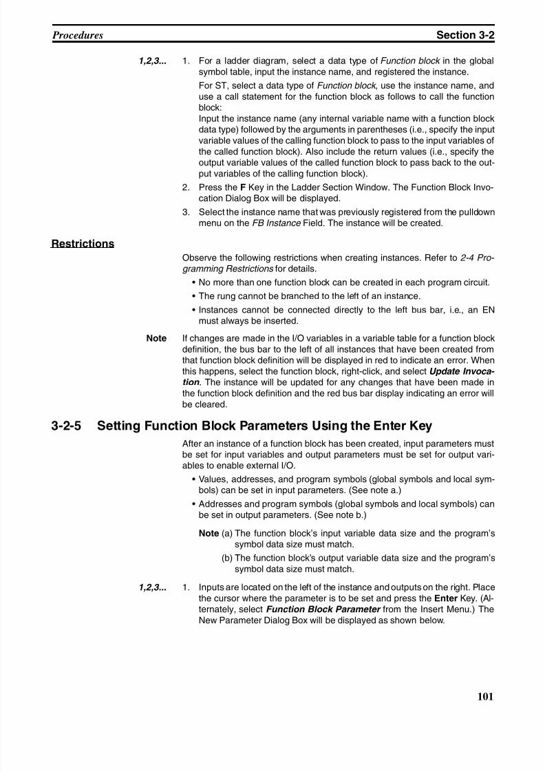
8/11/2019 CX-Programmer V9 Operation Manual FB ST.pdf
http://slidepdf.com/reader/full/cx-programmer-v9-operation-manual-fb-stpdf 127/254
101
Procedures Section 3-2
1,2,3... 1. For a ladder diagram, select a data type of Function block in the globalsymbol table, input the instance name, and registered the instance.
For ST, select a data type of Function block , use the instance name, anduse a call statement for the function block as follows to call the functionblock:Input the instance name (any internal variable name with a function blockdata type) followed by the arguments in parentheses (i.e., specify the inputvariable values of the calling function block to pass to the input variables ofthe called function block). Also include the return values (i.e., specify theoutput variable values of the called function block to pass back to the out-put variables of the calling function block).
2. Press the F Key in the Ladder Section Window. The Function Block Invo-cation Dialog Box will be displayed.
3. Select the instance name that was previously registered from the pulldownmenu on the FB Instance Field. The instance will be created.
Restrictions
Observe the following restrictions when creating instances. Refer to 2-4 Pro-
gramming Restrictions for details.• No more than one function block can be created in each program circuit.
• The rung cannot be branched to the left of an instance.
• Instances cannot be connected directly to the left bus bar, i.e., an ENmust always be inserted.
Note If changes are made in the I/O variables in a variable table for a function blockdefinition, the bus bar to the left of all instances that have been created fromthat function block definition will be displayed in red to indicate an error. Whenthis happens, select the function block, right-click, and select Update Invoca- tion . The instance will be updated for any changes that have been made inthe function block definition and the red bus bar display indicating an error will
be cleared.
3-2-5 Setting Function Block Parameters Using the Enter Key
After an instance of a function block has been created, input parameters mustbe set for input variables and output parameters must be set for output vari-ables to enable external I/O.
• Values, addresses, and program symbols (global symbols and local sym-bols) can be set in input parameters. (See note a.)
• Addresses and program symbols (global symbols and local symbols) canbe set in output parameters. (See note b.)
Note (a) The function block’s input variable data size and the program’s
symbol data size must match.
(b) The function block’s output variable data size and the program’ssymbol data size must match.
1,2,3... 1. Inputs are located on the left of the instance and outputs on the right. Placethe cursor where the parameter is to be set and press the Enter Key. (Al-ternately, select Function Block Parameter from the Insert Menu.) TheNew Parameter Dialog Box will be displayed as shown below.
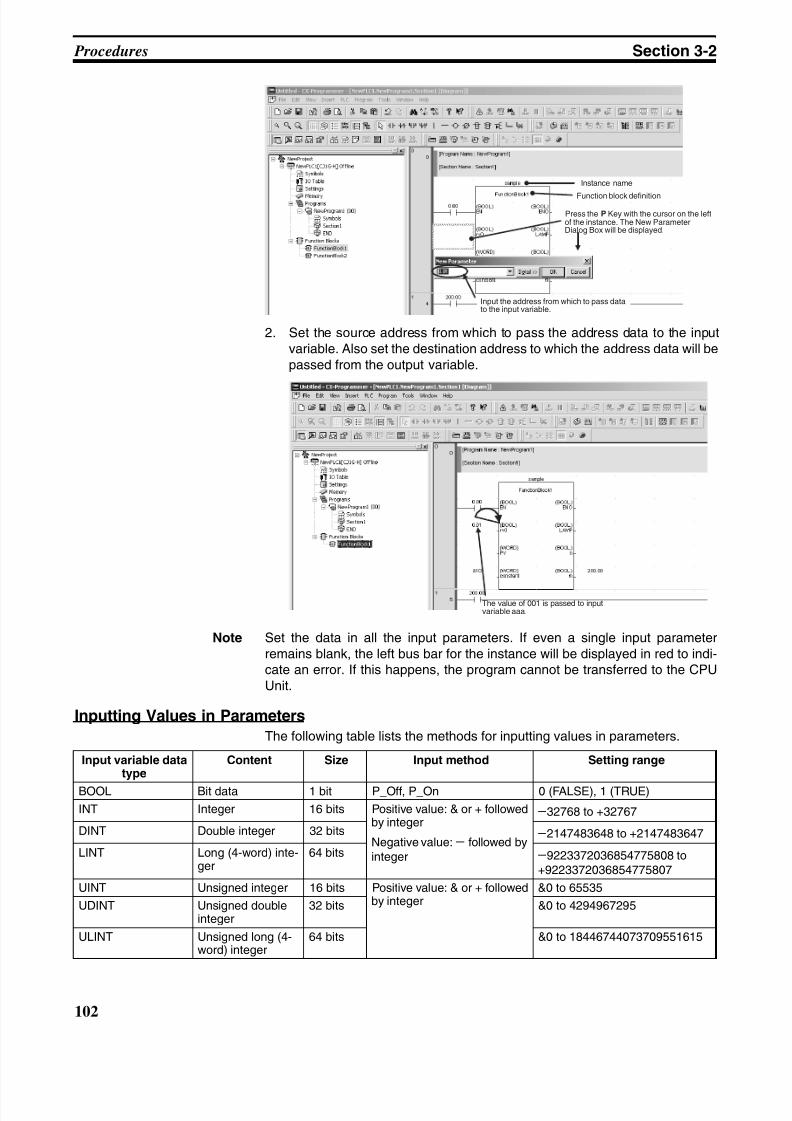
8/11/2019 CX-Programmer V9 Operation Manual FB ST.pdf
http://slidepdf.com/reader/full/cx-programmer-v9-operation-manual-fb-stpdf 128/254
102
Procedures Section 3-2
2. Set the source address from which to pass the address data to the inputvariable. Also set the destination address to which the address data will bepassed from the output variable.
Note Set the data in all the input parameters. If even a single input parameterremains blank, the left bus bar for the instance will be displayed in red to indi-cate an error. If this happens, the program cannot be transferred to the CPUUnit.
Inputting Values in Parameters
The following table lists the methods for inputting values in parameters.
Instance name
Function block definition
Press the P Key with the cursor on the leftof the instance. The New ParameterDialog Box will be displayed.
Input the address from which to pass datato the input variable.
The value of 001 is passed to inputvariable aaa.
Input variable datatype
Content Size Input method Setting range
BOOL Bit data 1 bit P_Off, P_On 0 (FALSE), 1 (TRUE)
INT Integer 16 bits Positive value: & or + followedby integer
Negative value: − followed byinteger
−32768 to +32767
DINT Double integer 32 bits −2147483648 to +2147483647
LINT Long (4-word) inte-ger
64 bits −9223372036854775808 to+9223372036854775807
UINT Unsigned integer 16 bits Positive value: & or + followedby integer
&0 to 65535
UDINT Unsigned doubleinteger
32 bits &0 to 4294967295
ULINT Unsigned long (4-word) integer
64 bits &0 to 18446744073709551615
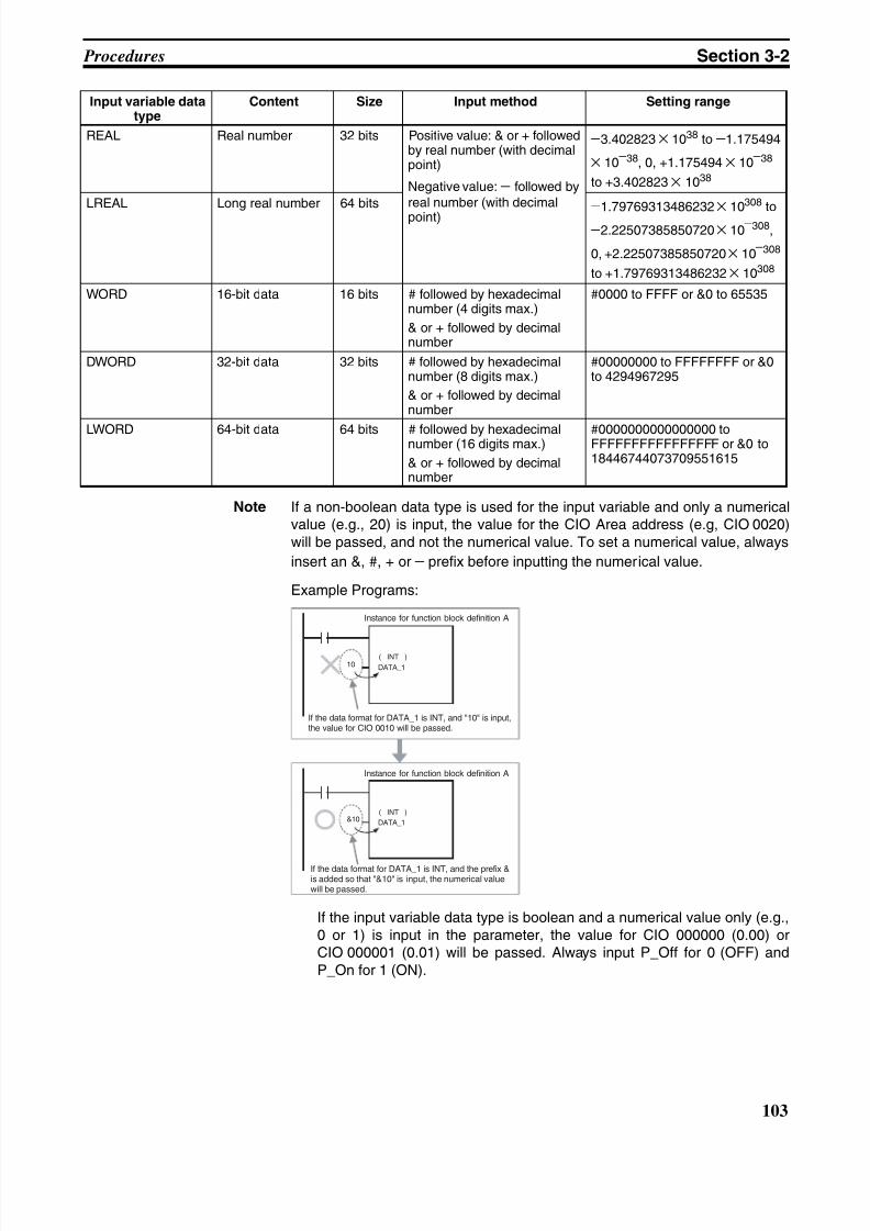
8/11/2019 CX-Programmer V9 Operation Manual FB ST.pdf
http://slidepdf.com/reader/full/cx-programmer-v9-operation-manual-fb-stpdf 129/254
103
Procedures Section 3-2
Note If a non-boolean data type is used for the input variable and only a numericalvalue (e.g., 20) is input, the value for the CIO Area address (e.g, CIO 0020)will be passed, and not the numerical value. To set a numerical value, always
insert an &, #, + or − prefix before inputting the numerical value.
Example Programs:
If the input variable data type is boolean and a numerical value only (e.g.,0 or 1) is input in the parameter, the value for CIO 000000 (0.00) orCIO 000001 (0.01) will be passed. Always input P_Off for 0 (OFF) andP_On for 1 (ON).
REAL Real number 32 bits Positive value: & or + followedby real number (with decimalpoint)
Negative value: − followed byreal number (with decimal
point)
−3.402823 × 1038 to −1.175494
× 10−38, 0, +1.175494 × 10
−38
to +3.402823 × 1038
LREAL Long real number 64 bits −1.79769313486232 × 10308 to
−2.22507385850720 × 10−308,
0, +2.22507385850720 × 10−308
to +1.79769313486232 × 10308
WORD 16-bit data 16 bits # followed by hexadecimalnumber (4 digits max.)
& or + followed by decimalnumber
#0000 to FFFF or &0 to 65535
DWORD 32-bit data 32 bits # followed by hexadecimalnumber (8 digits max.)
& or + followed by decimalnumber
#00000000 to FFFFFFFF or &0to 4294967295
LWORD 64-bit data 64 bits # followed by hexadecimalnumber (16 digits max.)
& or + followed by decimalnumber
#0000000000000000 toFFFFFFFFFFFFFFFF or &0 to18446744073709551615
Input variable datatype
Content Size Input method Setting range
10 DATA_1
&10 DATA_1
( INT )
( INT )
Instance for function block definition A
If the data format for DATA_1 is INT, and "10" is input,the value for CIO 0010 will be passed.
Instance for function block definition A
If the data format for DATA_1 is INT, and the prefix &is added so that "&10" is input, the numerical valuewill be passed.
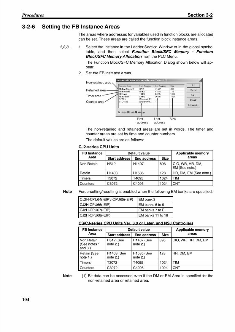
8/11/2019 CX-Programmer V9 Operation Manual FB ST.pdf
http://slidepdf.com/reader/full/cx-programmer-v9-operation-manual-fb-stpdf 130/254
104
Procedures Section 3-2
3-2-6 Setting the FB Instance Areas
The areas where addresses for variables used in function blocks are allocatedcan be set. These areas are called the function block instance areas.
1,2,3... 1. Select the instance in the Ladder Section Window or in the global symboltable, and then select Function Block/SFC Memory - Function
Block/SFC Memory Allocation from the PLC Menu.The Function Block/SFC Memory Allocation Dialog shown below will ap-pear.
2. Set the FB instance areas.
The non-retained and retained areas are set in words. The timer andcounter areas are set by time and counter numbers.
The default values are as follows:
CJ2-series CPU Units
Note Force-setting/resetting is enabled when the following EM banks are specified:
CS/CJ-series CPU Units Ver. 3.0 or Later, and NSJ Controllers
Note (1) Bit data can be accessed even if the DM or EM Area is specified for thenon-retained area or retained area.
FB InstanceArea
Default value Applicable memoryareasStart address End address Size
Non Retain H512 H1407 896 CIO, WR, HR, DM,EM (See note.)
Retain H1408 H1535 128 HR, DM, EM (See note.)Timers T3072 T4095 1024 TIM
Counters C3072 C4095 1024 CNT
Non-retained area
Retained area
Counter area
Timer area
Firstaddress
Lastaddress
Size
CJ2H-CPU64(-EIP)/-CPU65(-EIP) EM bank 3
CJ2H-CPU66(-EIP) EM banks 6 to 9
CJ2H-CPU67(-EIP) EM banks 7 to E
CJ2H-CPU68(-EIP) EM banks 11 to 18
FB Instance
Area
Default value Applicable memory
areasStart address End address Size
Non Retain(See notes 1and 3.)
H512 (Seenote 2.)
H1407 (Seenote 2.)
896 CIO, WR, HR, DM, EM
Retain (Seenote 1.)
H1408 (Seenote 2.)
H1535 (Seenote 2.)
128 HR, DM, EM
Timers T3072 T4095 1024 TIM
Counters C3072 C4095 1024 CNT
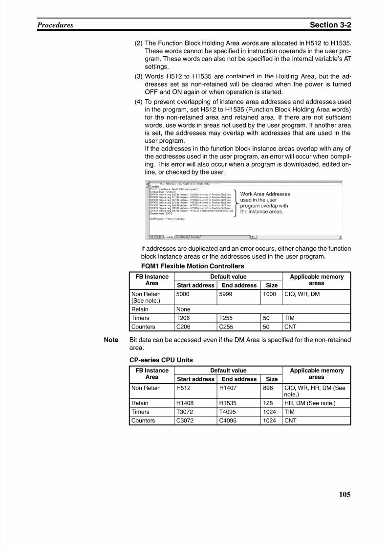
8/11/2019 CX-Programmer V9 Operation Manual FB ST.pdf
http://slidepdf.com/reader/full/cx-programmer-v9-operation-manual-fb-stpdf 131/254
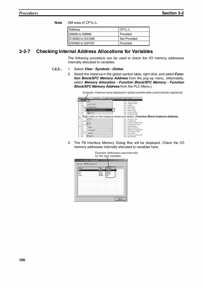
8/11/2019 CX-Programmer V9 Operation Manual FB ST.pdf
http://slidepdf.com/reader/full/cx-programmer-v9-operation-manual-fb-stpdf 132/254
106
Procedures Section 3-2
Note DM area of CP1L-L
3-2-7 Checking Internal Address Allocations for VariablesThe following procedure can be used to check the I/O memory addressesinternally allocated to variables.
1,2,3... 1. Select View - Symbols - Global.
2. Select the instance in the global symbol table, right-click, and select Func- tion Block/SFC Memory Address from the pop-up menu. (Alternately,select Memory Allocation - Function Block/SFC Memory - Function
Block/SFC Memory Address from the PLC Menu.)
3. The FB Interface Memory Dialog Box will be displayed. Check the I/Omemory addresses internally allocated to variables here.
Address CP1L-L
D0000 to D9999 Provided
D10000 to D31999 Not Provided
D32000 to D32767 Provided
Example: Instance name displayed in global variable table (automatically registered)
Right-click on the instance name and select Function Block Instance Address.
Example: Addresses used internallyfor the input variables.
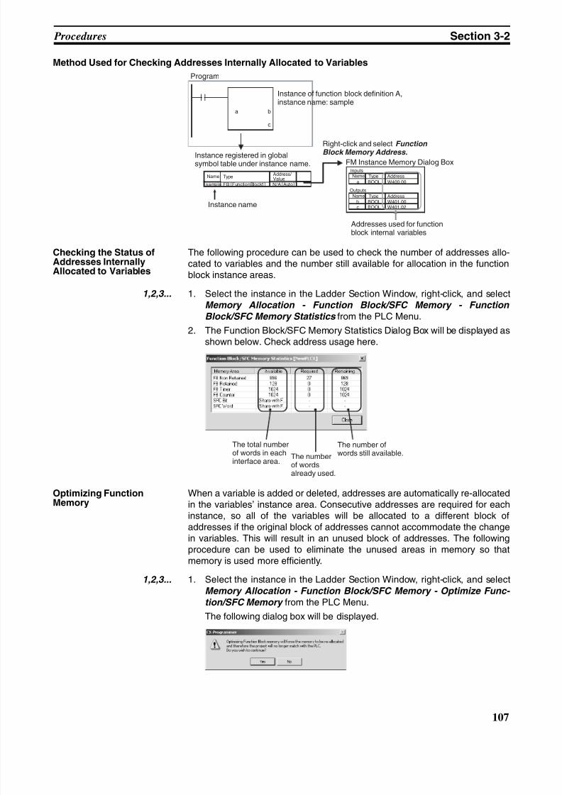
8/11/2019 CX-Programmer V9 Operation Manual FB ST.pdf
http://slidepdf.com/reader/full/cx-programmer-v9-operation-manual-fb-stpdf 133/254
8/11/2019 CX-Programmer V9 Operation Manual FB ST.pdf
http://slidepdf.com/reader/full/cx-programmer-v9-operation-manual-fb-stpdf 134/254
108
Procedures Section 3-2
2. Click the OK Button. Allocations to the function block instance areas willbe optimized.
3-2-8 Copying and Editing Function Block Definitions
Use the following operation to copy and edit the function block definition thathas been created.
1. Select the function block to copy, right-click, and select Copy from the pop-up menu.
2. Position the cursor over the function block item under the PLC in theproject directory, right-click and select Paste from the pop-up menu.
3. The function block definition will be copied (“copy” is indicated before thename of the function block definition at the copy source).
4. To change the function block name, left-click or right-click and select Re- name from the pop-up menu.
5. Double-click the function block definition to edit it.
3-2-9 Checking the Source Function Block Definition from an Instance
Use the following procedure to check the function block definition from whichan instance was created.
Either double-click the instance or right-click the instance and select To Lower Layer from the pop-up menu. The function block definition will be dis-played.
3-2-10 Checking Instance Information such as Nesting Levels
When function blocks are nested in the created program, the structure of thenesting levels can be checked by selecting Windows - FB Instance Viewer from the View Menu. The function block relationships will be shown in a direc-tory tree format, with the calling function blocks at the higher level and the
called function blocks at the lower level.The FB Instance Viewer Window will provide other information, such as thearray variables being used and internal addresses allocated to the variables,as shown in the following diagram. Variables can be registered in the WatchWindow just by dragging the variable from the list of variables used in theinstance and dropping the variable in the Watch Window.
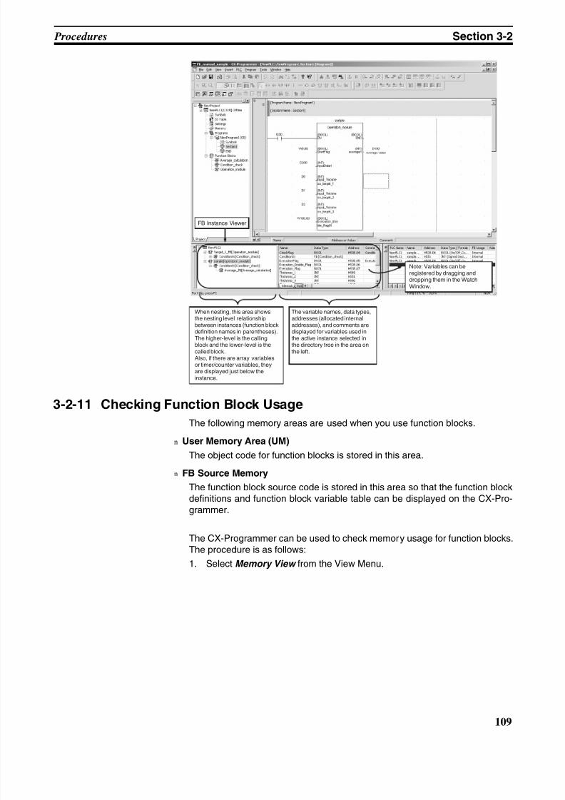
8/11/2019 CX-Programmer V9 Operation Manual FB ST.pdf
http://slidepdf.com/reader/full/cx-programmer-v9-operation-manual-fb-stpdf 135/254
109
Procedures Section 3-2
3-2-11 Checking Function Block Usage
The following memory areas are used when you use function blocks.
n User Memory Area (UM)
The object code for function blocks is stored in this area.
n FB Source Memory
The function block source code is stored in this area so that the function blockdefinitions and function block variable table can be displayed on the CX-Pro-grammer.
The CX-Programmer can be used to check memory usage for function blocks.The procedure is as follows:
1. Select Memory View from the View Menu.
When nesting, this area showsthe nesting level relationshipbetween instances (function blockdefinition names in parentheses).The higher-level is the callingblock and the lower-level is thecalled block.Also, if there are array variablesor timer/counter variables, theyare displayed just below theinstance.
The variable names, data types,addresses (allocated internaladdresses), and comments aredisplayed for variables used inthe active instance selected inthe directory tree in the area onthe left.
FB Instance Viewer
Note: Variables can beregistered by dragging and
dropping them in the WatchWindow.
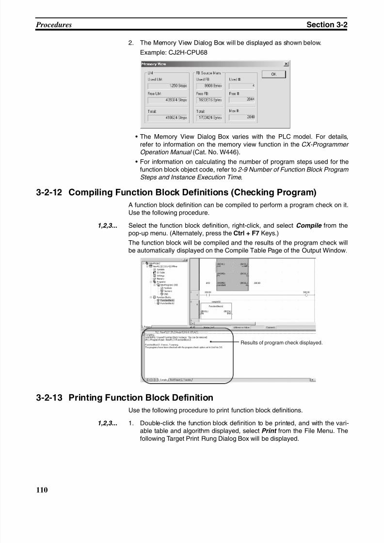
8/11/2019 CX-Programmer V9 Operation Manual FB ST.pdf
http://slidepdf.com/reader/full/cx-programmer-v9-operation-manual-fb-stpdf 136/254
110
Procedures Section 3-2
2. The Memory View Dialog Box will be displayed as shown below.
Example: CJ2H-CPU68
• The Memory View Dialog Box varies with the PLC model. For details,refer to information on the memory view function in the CX-Programmer Operation Manual (Cat. No. W446).
• For information on calculating the number of program steps used for thefunction block object code, refer to 2-9 Number of Function Block Program Steps and Instance Execution Time .
3-2-12 Compiling Function Block Definitions (Checking Program)A function block definition can be compiled to perform a program check on it.Use the following procedure.
1,2,3... Select the function block definition, right-click, and select Compile from thepop-up menu. (Alternately, press the Ctrl + F7 Keys.)
The function block will be compiled and the results of the program check willbe automatically displayed on the Compile Table Page of the Output Window.
3-2-13 Printing Function Block Definition
Use the following procedure to print function block definitions.
1,2,3... 1. Double-click the function block definition to be printed, and with the vari-able table and algorithm displayed, select Print from the File Menu. Thefollowing Target Print Rung Dialog Box will be displayed.
Results of program check displayed.
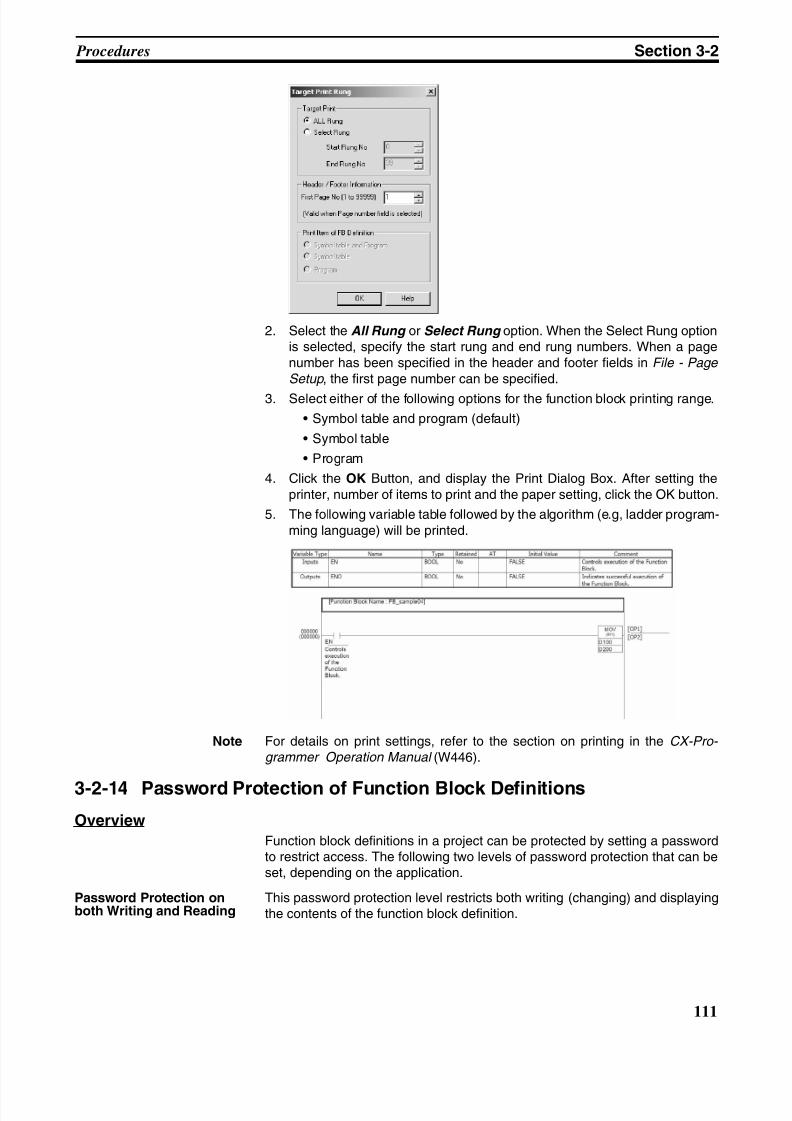
8/11/2019 CX-Programmer V9 Operation Manual FB ST.pdf
http://slidepdf.com/reader/full/cx-programmer-v9-operation-manual-fb-stpdf 137/254
111
Procedures Section 3-2
2. Select the All Rung or Select Rung option. When the Select Rung optionis selected, specify the start rung and end rung numbers. When a pagenumber has been specified in the header and footer fields in File - Page
Setup , the first page number can be specified.
3. Select either of the following options for the function block printing range.
• Symbol table and program (default)
• Symbol table
• Program
4. Click the OK Button, and display the Print Dialog Box. After setting theprinter, number of items to print and the paper setting, click the OK button.
5. The following variable table followed by the algorithm (e.g, ladder program-ming language) will be printed.
Note For details on print settings, refer to the section on printing in the CX-Pro- grammer Operation Manual (W446).
3-2-14 Password Protection of Function Block Definitions
Overview
Function block definitions in a project can be protected by setting a passwordto restrict access. The following two levels of password protection that can beset, depending on the application.
Password Protection onboth Writing and Reading
This password protection level restricts both writing (changing) and displayingthe contents of the function block definition.
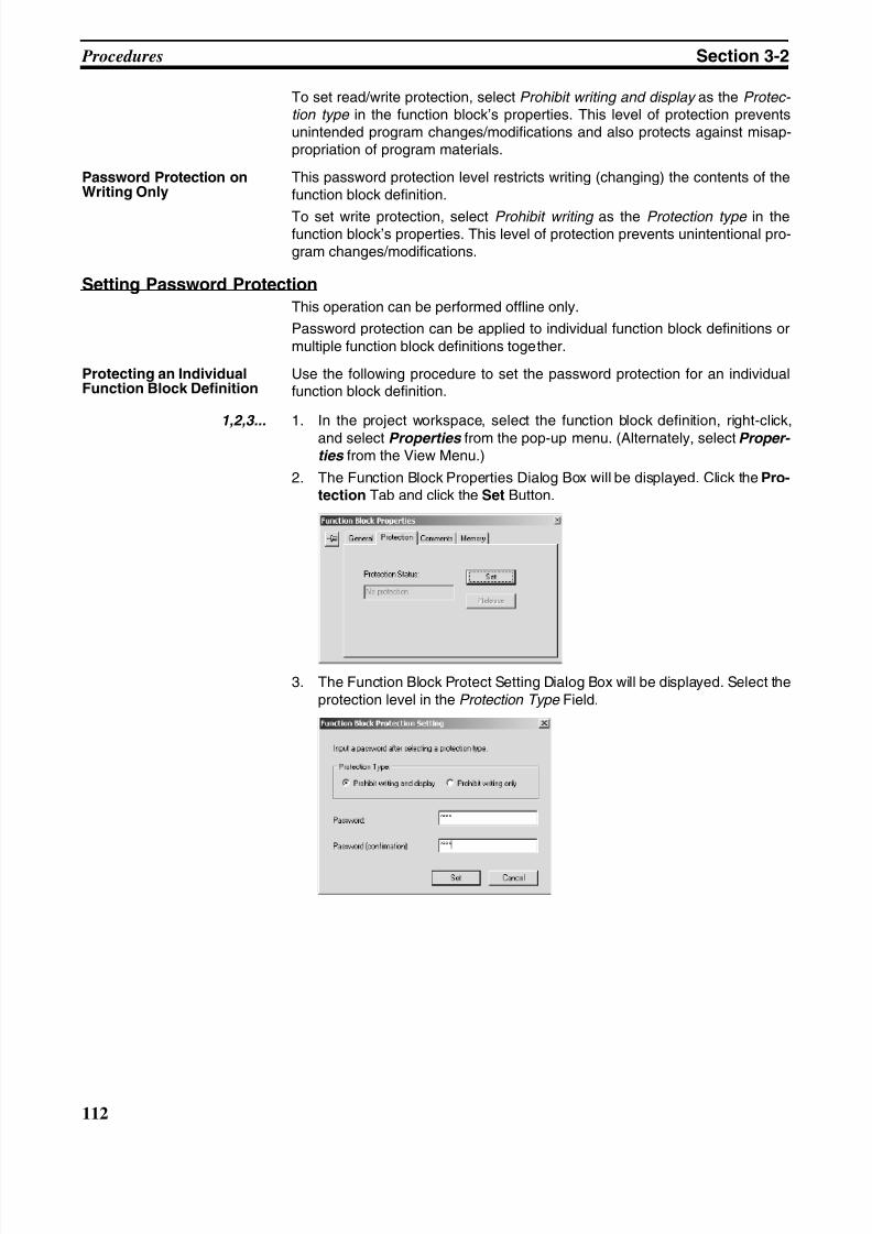
8/11/2019 CX-Programmer V9 Operation Manual FB ST.pdf
http://slidepdf.com/reader/full/cx-programmer-v9-operation-manual-fb-stpdf 138/254
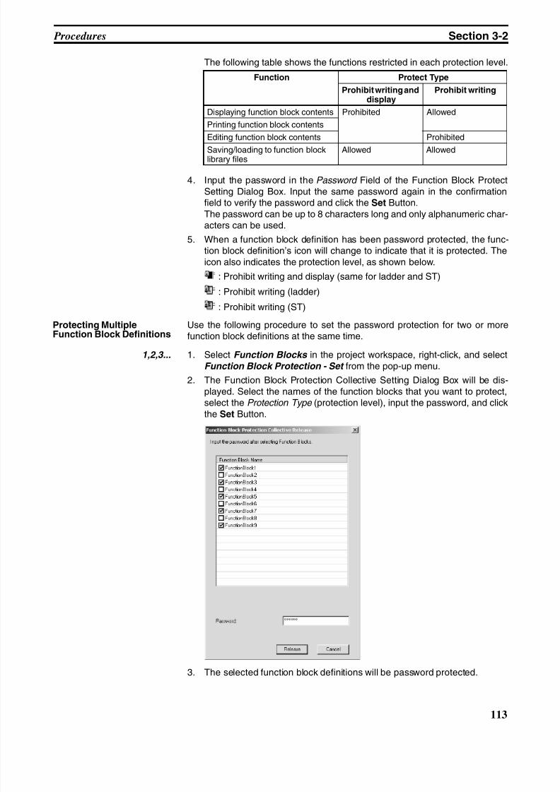
8/11/2019 CX-Programmer V9 Operation Manual FB ST.pdf
http://slidepdf.com/reader/full/cx-programmer-v9-operation-manual-fb-stpdf 139/254
113
Procedures Section 3-2
The following table shows the functions restricted in each protection level.
4. Input the password in the Password Field of the Function Block ProtectSetting Dialog Box. Input the same password again in the confirmationfield to verify the password and click the Set Button.The password can be up to 8 characters long and only alphanumeric char-acters can be used.
5. When a function block definition has been password protected, the func-tion block definition’s icon will change to indicate that it is protected. Theicon also indicates the protection level, as shown below.
: Prohibit writing and display (same for ladder and ST): Prohibit writing (ladder)
: Prohibit writing (ST)
Protecting MultipleFunction Block Definitions
Use the following procedure to set the password protection for two or morefunction block definitions at the same time.
1,2,3... 1. Select Function Blocks in the project workspace, right-click, and selectFunction Block Protection - Set from the pop-up menu.
2. The Function Block Protection Collective Setting Dialog Box will be dis-played. Select the names of the function blocks that you want to protect,select the Protection Type (protection level), input the password, and click
the Set Button.
3. The selected function block definitions will be password protected.
Function Protect Type
Prohibit writing anddisplay
Prohibit writing
Displaying function block contents Prohibited Allowed
Printing function block contents
Editing function block contents ProhibitedSaving/loading to function blocklibrary files
Allowed Allowed
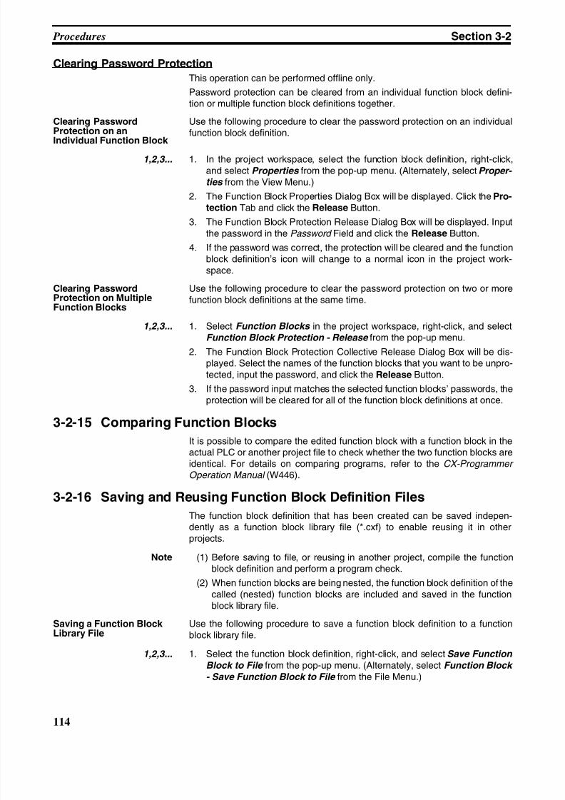
8/11/2019 CX-Programmer V9 Operation Manual FB ST.pdf
http://slidepdf.com/reader/full/cx-programmer-v9-operation-manual-fb-stpdf 140/254
114
Procedures Section 3-2
Clearing Password Protection
This operation can be performed offline only.
Password protection can be cleared from an individual function block defini-tion or multiple function block definitions together.
Clearing PasswordProtection on an
Individual Function Block
Use the following procedure to clear the password protection on an individualfunction block definition.
1,2,3... 1. In the project workspace, select the function block definition, right-click,and select Properties from the pop-up menu. (Alternately, select Proper- ties from the View Menu.)
2. The Function Block Properties Dialog Box will be displayed. Click the Pro-tection Tab and click the Release Button.
3. The Function Block Protection Release Dialog Box will be displayed. Inputthe password in the Password Field and click the Release Button.
4. If the password was correct, the protection will be cleared and the functionblock definition’s icon will change to a normal icon in the project work-space.
Clearing PasswordProtection on MultipleFunction Blocks
Use the following procedure to clear the password protection on two or morefunction block definitions at the same time.
1,2,3... 1. Select Function Blocks in the project workspace, right-click, and selectFunction Block Protection - Release from the pop-up menu.
2. The Function Block Protection Collective Release Dialog Box will be dis-played. Select the names of the function blocks that you want to be unpro-tected, input the password, and click the Release Button.
3. If the password input matches the selected function blocks’ passwords, theprotection will be cleared for all of the function block definitions at once.
3-2-15 Comparing Function BlocksIt is possible to compare the edited function block with a function block in theactual PLC or another project file to check whether the two function blocks areidentical. For details on comparing programs, refer to the CX-Programmer Operation Manual (W446).
3-2-16 Saving and Reusing Function Block Definition Files
The function block definition that has been created can be saved indepen-dently as a function block library file (*.cxf) to enable reusing it in otherprojects.
Note (1) Before saving to file, or reusing in another project, compile the functionblock definition and perform a program check.
(2) When function blocks are being nested, the function block definition of thecalled (nested) function blocks are included and saved in the functionblock library file.
Saving a Function BlockLibrary File
Use the following procedure to save a function block definition to a functionblock library file.
1,2,3... 1. Select the function block definition, right-click, and select Save Function
Block to File from the pop-up menu. (Alternately, select Function Block
- Save Function Block to File from the File Menu.)
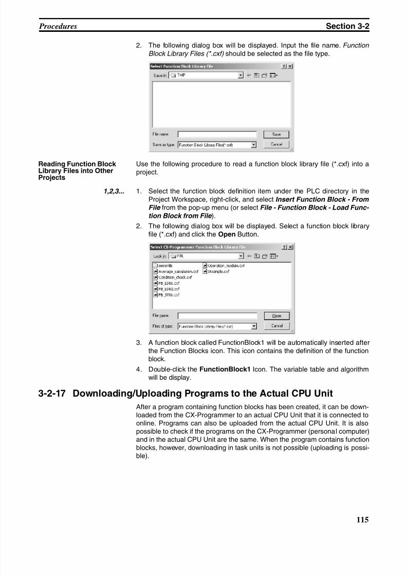
8/11/2019 CX-Programmer V9 Operation Manual FB ST.pdf
http://slidepdf.com/reader/full/cx-programmer-v9-operation-manual-fb-stpdf 141/254
115
Procedures Section 3-2
2. The following dialog box will be displayed. Input the file name. Function
Block Library Files (*.cxf) should be selected as the file type.
Reading Function BlockLibrary Files into OtherProjects
Use the following procedure to read a function block library file (*.cxf) into aproject.
1,2,3... 1. Select the function block definition item under the PLC directory in the
Project Workspace, right-click, and select Insert Function Block - From File from the pop-up menu (or select File - Function Block - Load Func-
tion Block from File ).
2. The following dialog box will be displayed. Select a function block libraryfile (*.cxf) and click the Open Button.
3. A function block called FunctionBlock1 will be automatically inserted afterthe Function Blocks icon. This icon contains the definition of the functionblock.
4. Double-click the FunctionBlock1 Icon. The variable table and algorithmwill be display.
3-2-17 Downloading/Uploading Programs to the Actual CPU Unit
After a program containing function blocks has been created, it can be down-loaded from the CX-Programmer to an actual CPU Unit that it is connected toonline. Programs can also be uploaded from the actual CPU Unit. It is alsopossible to check if the programs on the CX-Programmer (personal computer)and in the actual CPU Unit are the same. When the program contains functionblocks, however, downloading in task units is not possible (uploading is possi-ble).
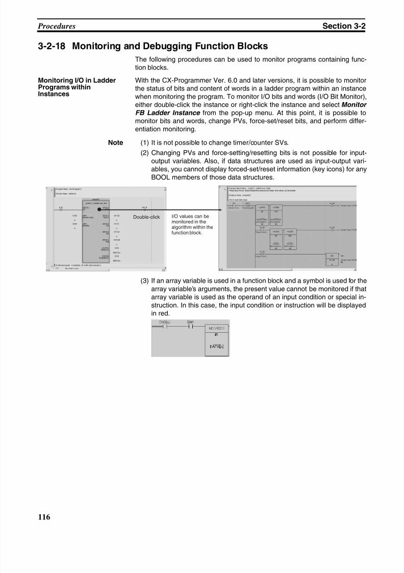
8/11/2019 CX-Programmer V9 Operation Manual FB ST.pdf
http://slidepdf.com/reader/full/cx-programmer-v9-operation-manual-fb-stpdf 142/254
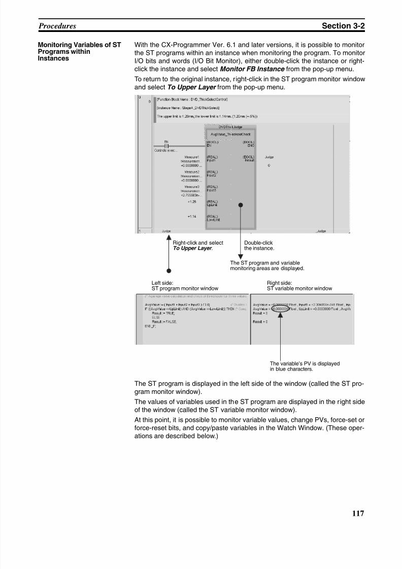
8/11/2019 CX-Programmer V9 Operation Manual FB ST.pdf
http://slidepdf.com/reader/full/cx-programmer-v9-operation-manual-fb-stpdf 143/254
117
Procedures Section 3-2
Monitoring Variables of STPrograms withinInstances
With the CX-Programmer Ver. 6.1 and later versions, it is possible to monitorthe ST programs within an instance when monitoring the program. To monitorI/O bits and words (I/O Bit Monitor), either double-click the instance or right-click the instance and select Monitor FB Instance from the pop-up menu.
To return to the original instance, right-click in the ST program monitor windowand select To Upper Layer from the pop-up menu.
The ST program is displayed in the left side of the window (called the ST pro-gram monitor window).
The values of variables used in the ST program are displayed in the right sideof the window (called the ST variable monitor window).
At this point, it is possible to monitor variable values, change PVs, force-set orforce-reset bits, and copy/paste variables in the Watch Window. (These oper-ations are described below.)
Left side:ST program monitor window
Right side:ST variable monitor window
Right-click and selectTo Upper Layer .
Double-clickthe instance.
The ST program and variablemonitoring areas are displayed.
The variable’s PV is displayedin blue characters.
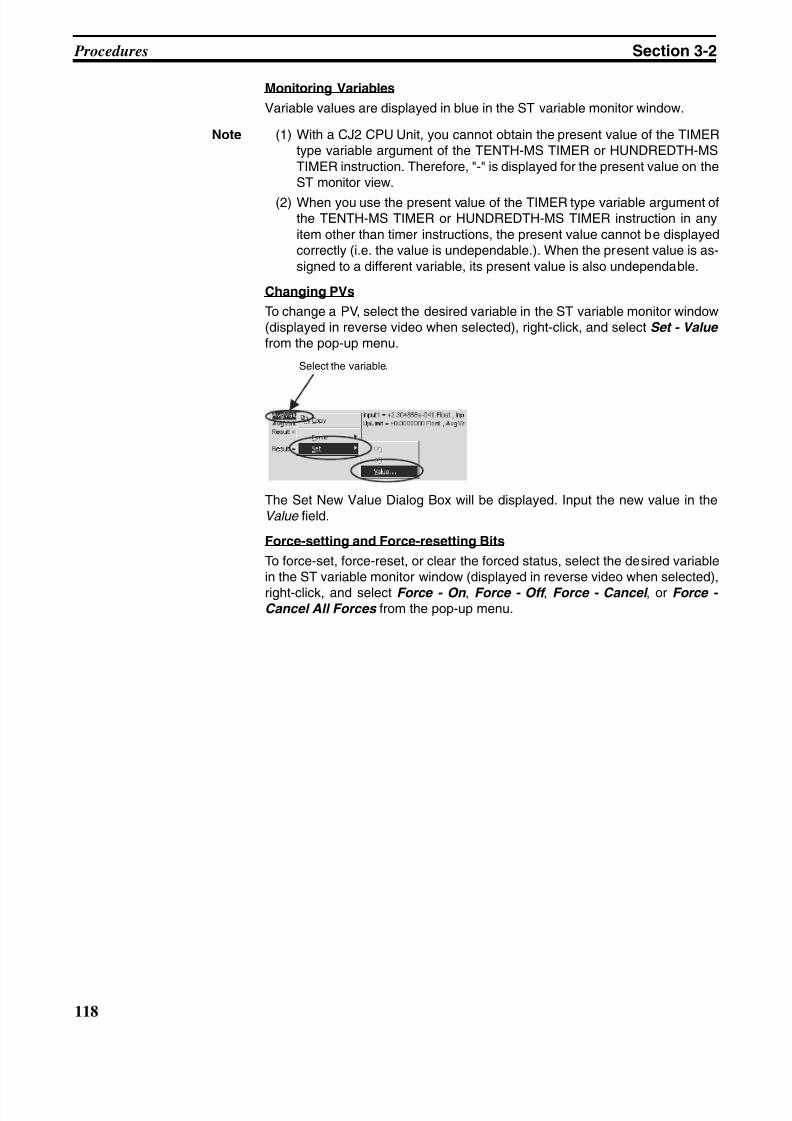
8/11/2019 CX-Programmer V9 Operation Manual FB ST.pdf
http://slidepdf.com/reader/full/cx-programmer-v9-operation-manual-fb-stpdf 144/254
118
Procedures Section 3-2
Monitoring Variables
Variable values are displayed in blue in the ST variable monitor window.
Note (1) With a CJ2 CPU Unit, you cannot obtain the present value of the TIMERtype variable argument of the TENTH-MS TIMER or HUNDREDTH-MSTIMER instruction. Therefore, "-" is displayed for the present value on theST monitor view.
(2) When you use the present value of the TIMER type variable argument ofthe TENTH-MS TIMER or HUNDREDTH-MS TIMER instruction in anyitem other than timer instructions, the present value cannot be displayedcorrectly (i.e. the value is undependable.). When the present value is as-signed to a different variable, its present value is also undependable.
Changing PVs
To change a PV, select the desired variable in the ST variable monitor window(displayed in reverse video when selected), right-click, and select Set - Value from the pop-up menu.
The Set New Value Dialog Box will be displayed. Input the new value in theValue field.
Force-setting and Force-resetting Bits
To force-set, force-reset, or clear the forced status, select the desired variablein the ST variable monitor window (displayed in reverse video when selected),
right-click, and select Force - On , Force - Off , Force - Cancel , or Force - Cancel All Forces from the pop-up menu.
Select the variable.
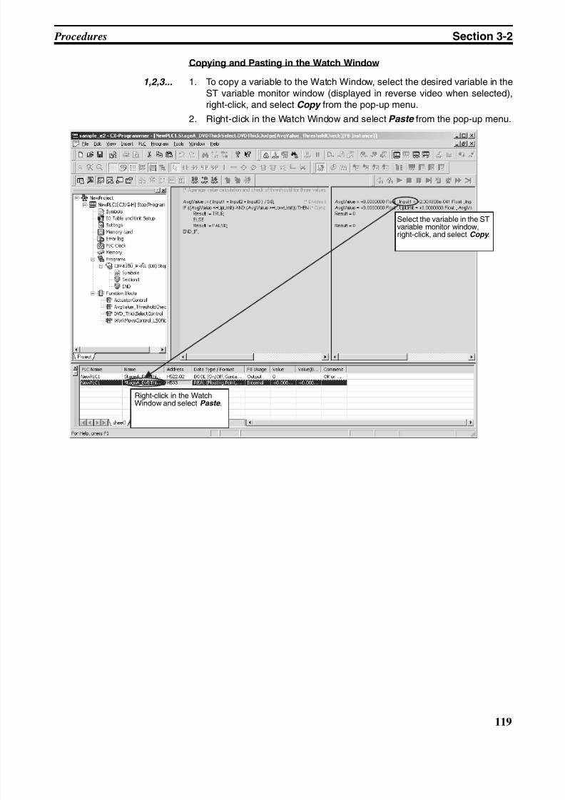
8/11/2019 CX-Programmer V9 Operation Manual FB ST.pdf
http://slidepdf.com/reader/full/cx-programmer-v9-operation-manual-fb-stpdf 145/254
119
Procedures Section 3-2
Copying and Pasting in the Watch Window
1,2,3... 1. To copy a variable to the Watch Window, select the desired variable in theST variable monitor window (displayed in reverse video when selected),right-click, and select Copy from the pop-up menu.
2. Right-click in the Watch Window and select Paste from the pop-up menu.
Select the variable in the STvariable monitor window,right-click, and select Copy .
Right-click in the WatchWindow and select Paste .
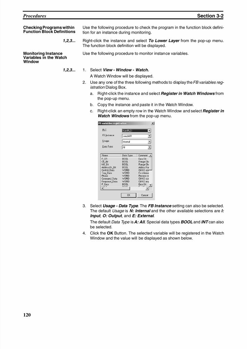
8/11/2019 CX-Programmer V9 Operation Manual FB ST.pdf
http://slidepdf.com/reader/full/cx-programmer-v9-operation-manual-fb-stpdf 146/254
120
Procedures Section 3-2
Checking Programs withinFunction Block Definitions
Use the following procedure to check the program in the function block defini-tion for an instance during monitoring.
1,2,3... Right-click the instance and select To Lower Layer from the pop-up menu.The function block definition will be displayed.
Monitoring InstanceVariables in the Watch
Window
Use the following procedure to monitor instance variables.
1,2,3... 1. Select View - Window - Watch.
A Watch Window will be displayed.
2. Use any one of the three following methods to display the FB variables reg- istration Dialog Box.
a. Right-click the instance and select Register in Watch Windows fromthe pop-up menu.
b. Copy the instance and paste it in the Watch Window.
c. Right-click an empty row in the Watch Window and select Register in Watch Windows from the pop-up menu.
3. Select Usage - Data Type . The FB Instance setting can also be selected.The default Usage is N: Internal and the other available selections are I: Input , O: Output , and E: External .
The default Data Type isA: All . Special data types BOOL and INT can alsobe selected.
4. Click the OK Button. The selected variable will be registered in the WatchWindow and the value will be displayed as shown below.
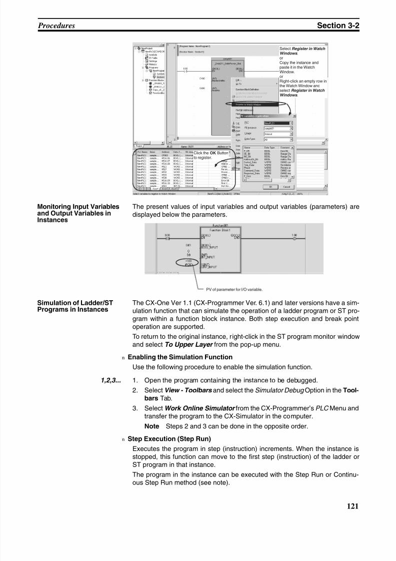
8/11/2019 CX-Programmer V9 Operation Manual FB ST.pdf
http://slidepdf.com/reader/full/cx-programmer-v9-operation-manual-fb-stpdf 147/254
121
Procedures Section 3-2
Monitoring Input Variablesand Output Variables inInstances
The present values of input variables and output variables (parameters) aredisplayed below the parameters.
Simulation of Ladder/STPrograms in Instances
The CX-One Ver 1.1 (CX-Programmer Ver. 6.1) and later versions have a sim-ulation function that can simulate the operation of a ladder program or ST pro-gram within a function block instance. Both step execution and break pointoperation are supported.
To return to the original instance, right-click in the ST program monitor windowand select To Upper Layer from the pop-up menu.
n Enabling the Simulation Function
Use the following procedure to enable the simulation function.
1,2,3... 1. Open the program containing the instance to be debugged.
2. Select View - Toolbars and select the Simulator Debug Option in the Tool-bars Tab.
3. Select Work Online Simulator from the CX-Programmer’s PLC Menu andtransfer the program to the CX-Simulator in the computer.
Note Steps 2 and 3 can be done in the opposite order.
n Step Execution (Step Run)
Executes the program in step (instruction) increments. When the instance isstopped, this function can move to the first step (instruction) of the ladder orST program in that instance.
The program in the instance can be executed with the Step Run or Continu-ous Step Run method (see note).
Click the OK Buttonto register.
Select Register in WatchWindows .orCopy the instance andpaste it in the WatchWindow.orRight-click an empty row inthe Watch Window andselect Register in WatchWindows .
PV of parameter for I/O variable.
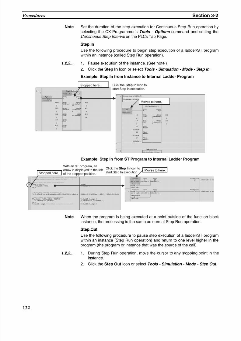
8/11/2019 CX-Programmer V9 Operation Manual FB ST.pdf
http://slidepdf.com/reader/full/cx-programmer-v9-operation-manual-fb-stpdf 148/254
122
Procedures Section 3-2
Note Set the duration of the step execution for Continuous Step Run operation byselecting the CX-Programmer’s Tools - Options command and setting theContinuous Step Interval on the PLCs Tab Page.
Step In
Use the following procedure to begin step execution of a ladder/ST programwithin an instance (called Step Run operation).
1,2,3... 1. Pause execution of the instance. (See note.)
2. Click the Step In Icon or select Tools - Simulation - Mode - Step In .
Example: Step In from Instance to Internal Ladder Program
Example: Step In from ST Program to Internal Ladder Program
Note When the program is being executed at a point outside of the function blockinstance, the processing is the same as normal Step Run operation.
Step Out
Use the following procedure to pause step execution of a ladder/ST program
within an instance (Step Run operation) and return to one level higher in theprogram (the program or instance that was the source of the call).
1,2,3... 1. During Step Run operation, move the cursor to any stopping point in theinstance.
2. Click the Step Out Icon or select Tools - Simulation - Mode - Step Out .
Stopped here.
Moves to here.
Click the Step In Icon tostart Step In execution.
Stopped here.Moves to here.
With an ST program, anarrow is displayed to the leftof the stopped position.
Click the Step In Icon tostart Step In execution.
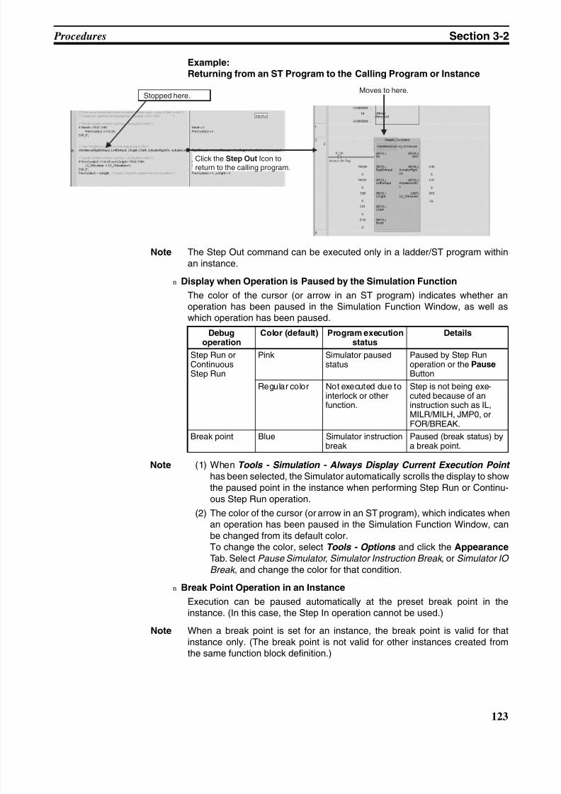
8/11/2019 CX-Programmer V9 Operation Manual FB ST.pdf
http://slidepdf.com/reader/full/cx-programmer-v9-operation-manual-fb-stpdf 149/254
123
Procedures Section 3-2
Example:Returning from an ST Program to the Calling Program or Instance
Note The Step Out command can be executed only in a ladder/ST program withinan instance.
n Display when Operation is Paused by the Simulation Function
The color of the cursor (or arrow in an ST program) indicates whether anoperation has been paused in the Simulation Function Window, as well aswhich operation has been paused.
Note (1) When Tools - Simulation - Always Display Current Execution Point
has been selected, the Simulator automatically scrolls the display to showthe paused point in the instance when performing Step Run or Continu-ous Step Run operation.
(2) The color of the cursor (or arrow in an ST program), which indicates whenan operation has been paused in the Simulation Function Window, canbe changed from its default color.To change the color, select Tools - Options and click the Appearance
Tab. Select Pause Simulator , Simulator Instruction Break , or Simulator IO Break , and change the color for that condition.
n Break Point Operation in an Instance
Execution can be paused automatically at the preset break point in theinstance. (In this case, the Step In operation cannot be used.)
Note When a break point is set for an instance, the break point is valid for thatinstance only. (The break point is not valid for other instances created fromthe same function block definition.)
Stopped here.Moves to here.
Click the Step Out Icon toreturn to the calling program.
Debugoperation
Color (default) Program executionstatus
Details
Step Run orContinuousStep Run
Pink Simulator pausedstatus
Paused by Step Runoperation or the Pause Button
Regular color Not executed due tointerlock or otherfunction.
Step is not being exe-cuted because of aninstruction such as IL,
MILR/MILH, JMP0, orFOR/BREAK.
Break point Blue Simulator instructionbreak
Paused (break status) bya break point.
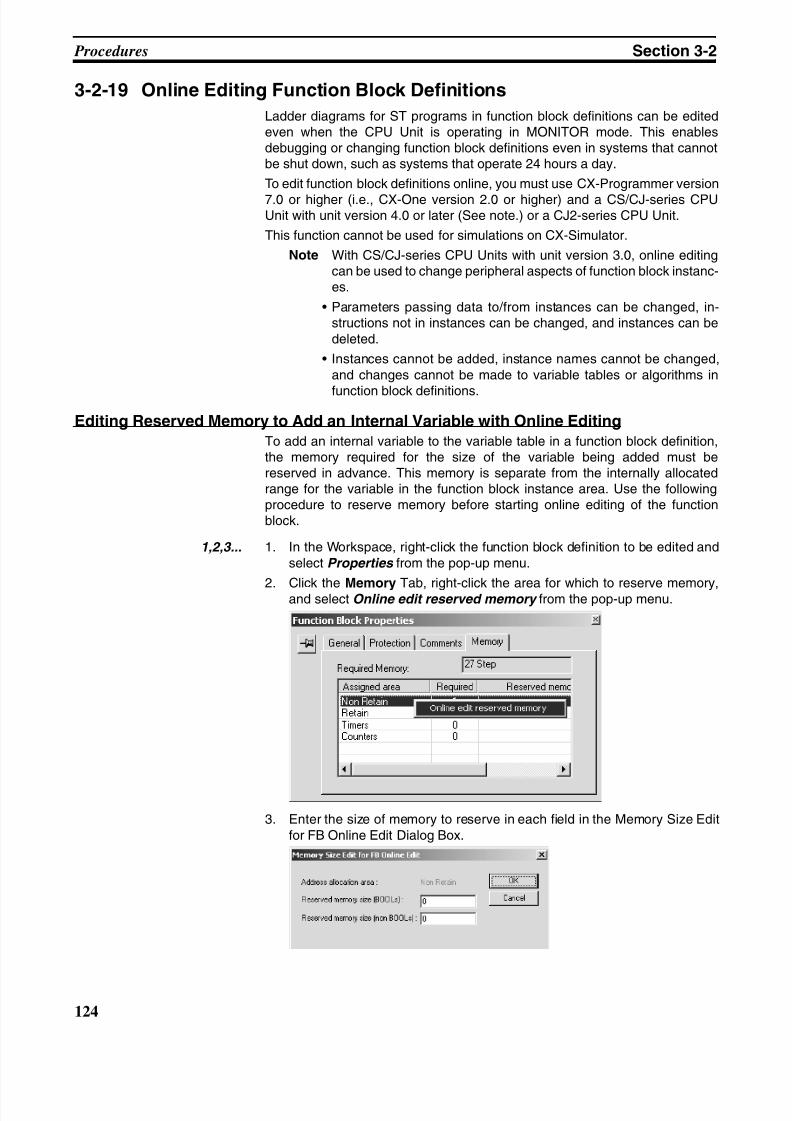
8/11/2019 CX-Programmer V9 Operation Manual FB ST.pdf
http://slidepdf.com/reader/full/cx-programmer-v9-operation-manual-fb-stpdf 150/254
124
Procedures Section 3-2
3-2-19 Online Editing Function Block Definitions
Ladder diagrams for ST programs in function block definitions can be editedeven when the CPU Unit is operating in MONITOR mode. This enablesdebugging or changing function block definitions even in systems that cannotbe shut down, such as systems that operate 24 hours a day.
To edit function block definitions online, you must use CX-Programmer version
7.0 or higher (i.e., CX-One version 2.0 or higher) and a CS/CJ-series CPUUnit with unit version 4.0 or later (See note.) or a CJ2-series CPU Unit.
This function cannot be used for simulations on CX-Simulator.
Note With CS/CJ-series CPU Units with unit version 3.0, online editingcan be used to change peripheral aspects of function block instanc-es.
• Parameters passing data to/from instances can be changed, in-structions not in instances can be changed, and instances can bedeleted.
• Instances cannot be added, instance names cannot be changed,and changes cannot be made to variable tables or algorithms in
function block definitions.
Editing Reserved Memory to Add an Internal Variable with Online Editing
To add an internal variable to the variable table in a function block definition,the memory required for the size of the variable being added must bereserved in advance. This memory is separate from the internally allocatedrange for the variable in the function block instance area. Use the followingprocedure to reserve memory before starting online editing of the functionblock.
1,2,3... 1. In the Workspace, right-click the function block definition to be edited andselect Properties from the pop-up menu.
2. Click the Memory Tab, right-click the area for which to reserve memory,and select Online edit reserved memory from the pop-up menu.
3. Enter the size of memory to reserve in each field in the Memory Size Editfor FB Online Edit Dialog Box.
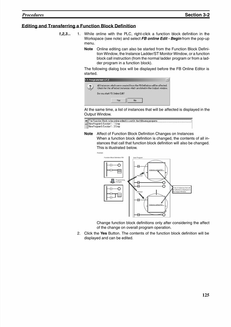
8/11/2019 CX-Programmer V9 Operation Manual FB ST.pdf
http://slidepdf.com/reader/full/cx-programmer-v9-operation-manual-fb-stpdf 151/254
125
Procedures Section 3-2
Editing and Transferring a Function Block Definition
1,2,3... 1. While online with the PLC, right-click a function block definition in theWorkspace (see note) and select FB online Edit - Begin from the pop-upmenu.
Note Online editing can also be started from the Function Block Defini-tion Window, the Instance Ladder/ST Monitor Window, or a function
block call instruction (from the normal ladder program or from a lad-der program in a function block).
The following dialog box will be displayed before the FB Online Editor isstarted.
At the same time, a list of instances that will be affected is displayed in the
Output Window.
Note Affect of Function Block Definition Changes on InstancesWhen a function block definition is changed, the contents of all in-stances that call that function block definition will also be changed.This is illustrated below.
Change function block definitions only after considering the affect
of the change on overall program operation.2. Click the Yes Button. The contents of the function block definition will be
displayed and can be edited.
User ProgramFunction Block Definition FB1
Instance call ing FB1
Affected
Programmingchanged.
Affected
Instance call ing FB1
Example
A list of instances that will
be affected is displayed inthe Output Window.
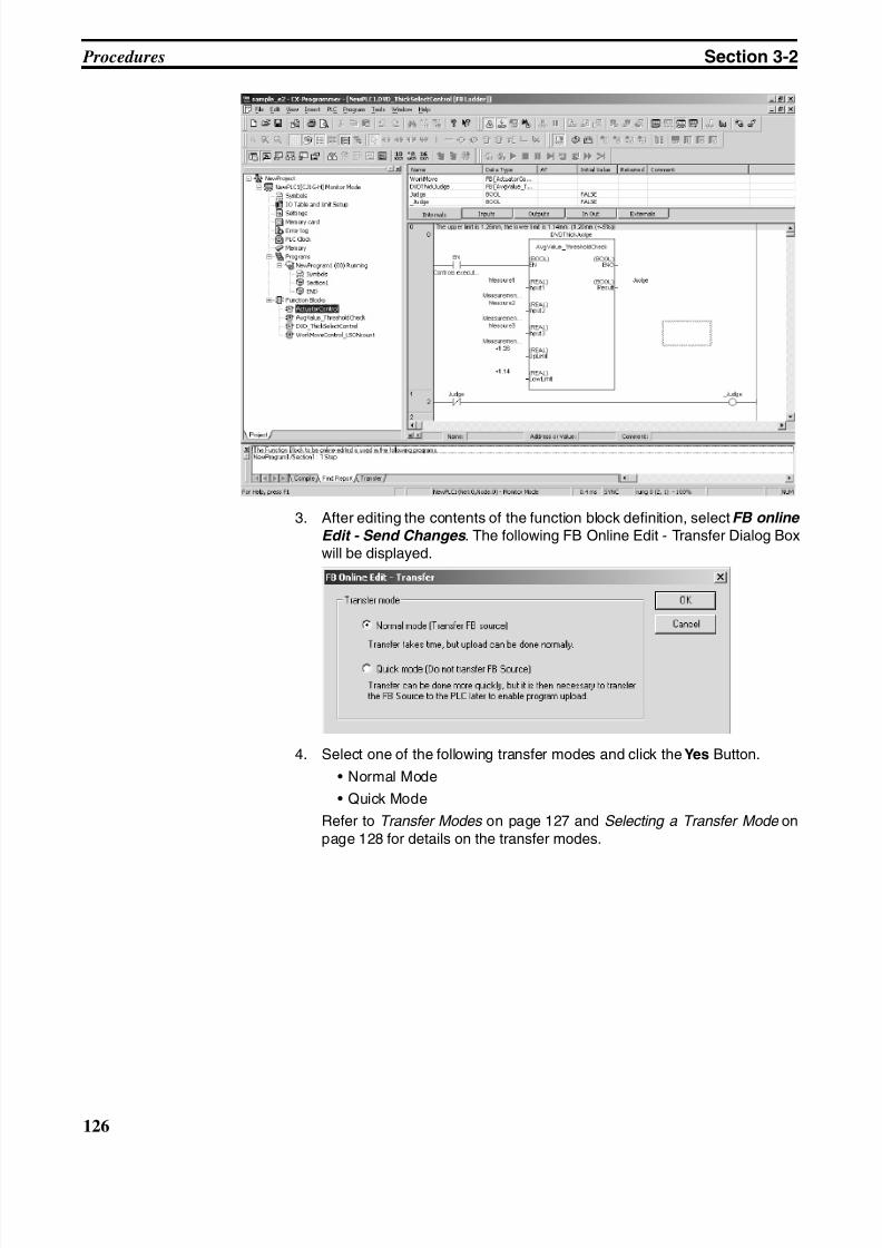
8/11/2019 CX-Programmer V9 Operation Manual FB ST.pdf
http://slidepdf.com/reader/full/cx-programmer-v9-operation-manual-fb-stpdf 152/254
126
Procedures Section 3-2
3. After editing the contents of the function block definition, select FB online
Edit - Send Changes . The following FB Online Edit - Transfer Dialog Boxwill be displayed.
4. Select one of the following transfer modes and click the Yes Button.
• Normal Mode
• Quick Mode
Refer to Transfer Modes on page 127 and Selecting a Transfer Mode onpage 128 for details on the transfer modes.
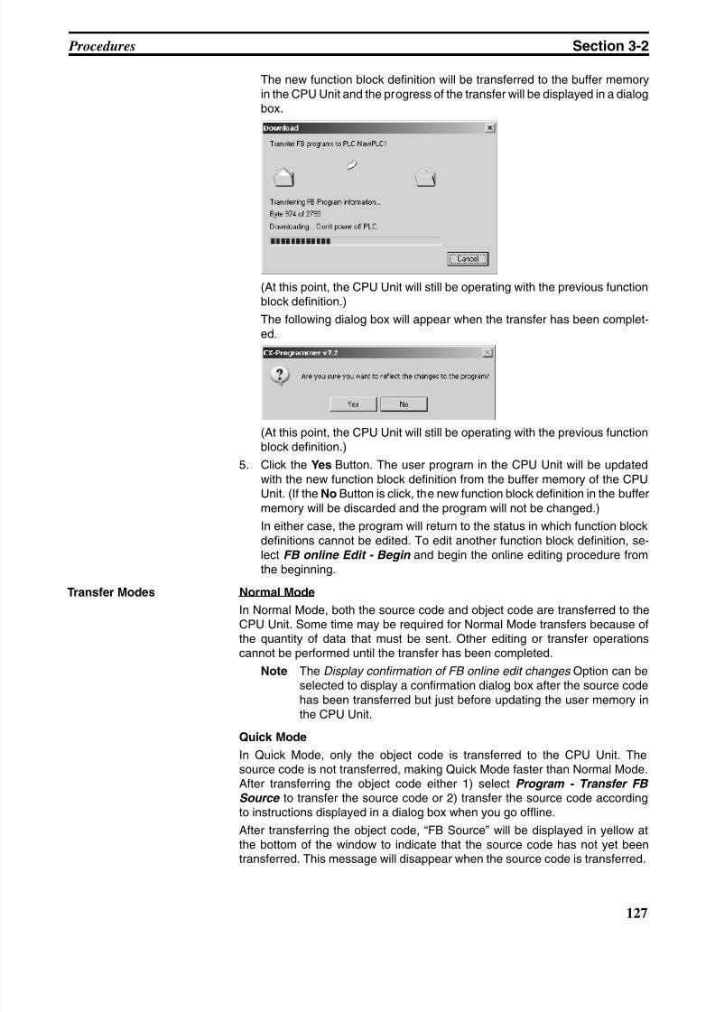
8/11/2019 CX-Programmer V9 Operation Manual FB ST.pdf
http://slidepdf.com/reader/full/cx-programmer-v9-operation-manual-fb-stpdf 153/254
127
Procedures Section 3-2
The new function block definition will be transferred to the buffer memoryin the CPU Unit and the progress of the transfer will be displayed in a dialogbox.
(At this point, the CPU Unit will still be operating with the previous functionblock definition.)
The following dialog box will appear when the transfer has been complet-ed.
(At this point, the CPU Unit will still be operating with the previous functionblock definition.)
5. Click the Yes Button. The user program in the CPU Unit will be updatedwith the new function block definition from the buffer memory of the CPUUnit. (If the No Button is click, the new function block definition in the buffermemory will be discarded and the program will not be changed.)
In either case, the program will return to the status in which function blockdefinitions cannot be edited. To edit another function block definition, se-lect FB online Edit - Begin and begin the online editing procedure fromthe beginning.
Transfer Modes Normal Mode
In Normal Mode, both the source code and object code are transferred to theCPU Unit. Some time may be required for Normal Mode transfers because ofthe quantity of data that must be sent. Other editing or transfer operationscannot be performed until the transfer has been completed.
Note The Display confirmation of FB online edit changes Option can beselected to display a confirmation dialog box after the source codehas been transferred but just before updating the user memory inthe CPU Unit.
Quick Mode
In Quick Mode, only the object code is transferred to the CPU Unit. Thesource code is not transferred, making Quick Mode faster than Normal Mode.After transferring the object code either 1) select Program - Transfer FB Source to transfer the source code or 2) transfer the source code accordingto instructions displayed in a dialog box when you go offline.
After transferring the object code, “FB Source” will be displayed in yellow atthe bottom of the window to indicate that the source code has not yet beentransferred. This message will disappear when the source code is transferred.
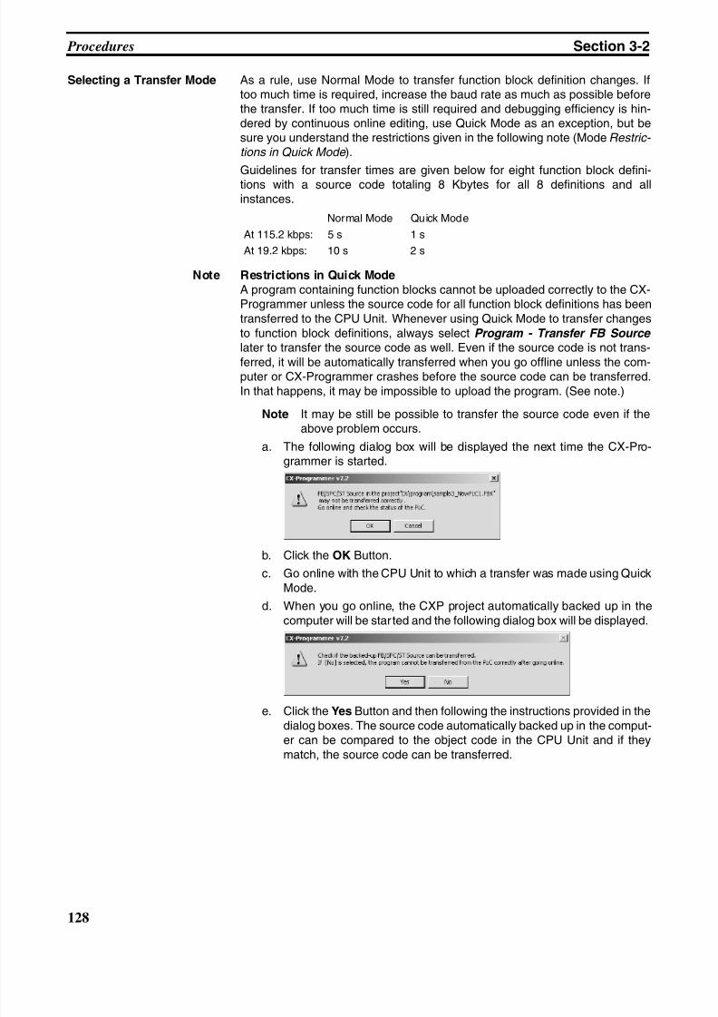
8/11/2019 CX-Programmer V9 Operation Manual FB ST.pdf
http://slidepdf.com/reader/full/cx-programmer-v9-operation-manual-fb-stpdf 154/254
128
Procedures Section 3-2
Selecting a Transfer Mode As a rule, use Normal Mode to transfer function block definition changes. Iftoo much time is required, increase the baud rate as much as possible beforethe transfer. If too much time is still required and debugging efficiency is hin-dered by continuous online editing, use Quick Mode as an exception, but besure you understand the restrictions given in the following note (Mode Restric- tions in Quick Mode ).
Guidelines for transfer times are given below for eight function block defini-tions with a source code totaling 8 Kbytes for all 8 definitions and allinstances.
Note Restrictions in Quick Mode
A program containing function blocks cannot be uploaded correctly to the CX-Programmer unless the source code for all function block definitions has beentransferred to the CPU Unit. Whenever using Quick Mode to transfer changesto function block definitions, always select Program - Transfer FB Source later to transfer the source code as well. Even if the source code is not trans-ferred, it will be automatically transferred when you go offline unless the com-puter or CX-Programmer crashes before the source code can be transferred.In that happens, it may be impossible to upload the program. (See note.)
Note It may be still be possible to transfer the source code even if theabove problem occurs.
a. The following dialog box will be displayed the next time the CX-Pro-grammer is started.
b. Click the OK Button.
c. Go online with the CPU Unit to which a transfer was made using QuickMode.
d. When you go online, the CXP project automatically backed up in thecomputer will be star ted and the following dialog box will be displayed.
e. Click the Yes Button and then following the instructions provided in thedialog boxes. The source code automatically backed up in the comput-er can be compared to the object code in the CPU Unit and if theymatch, the source code can be transferred.
Normal Mode Quick Mode
At 115.2 kbps: 5 s 1 s
At 19.2 kbps: 10 s 2 s
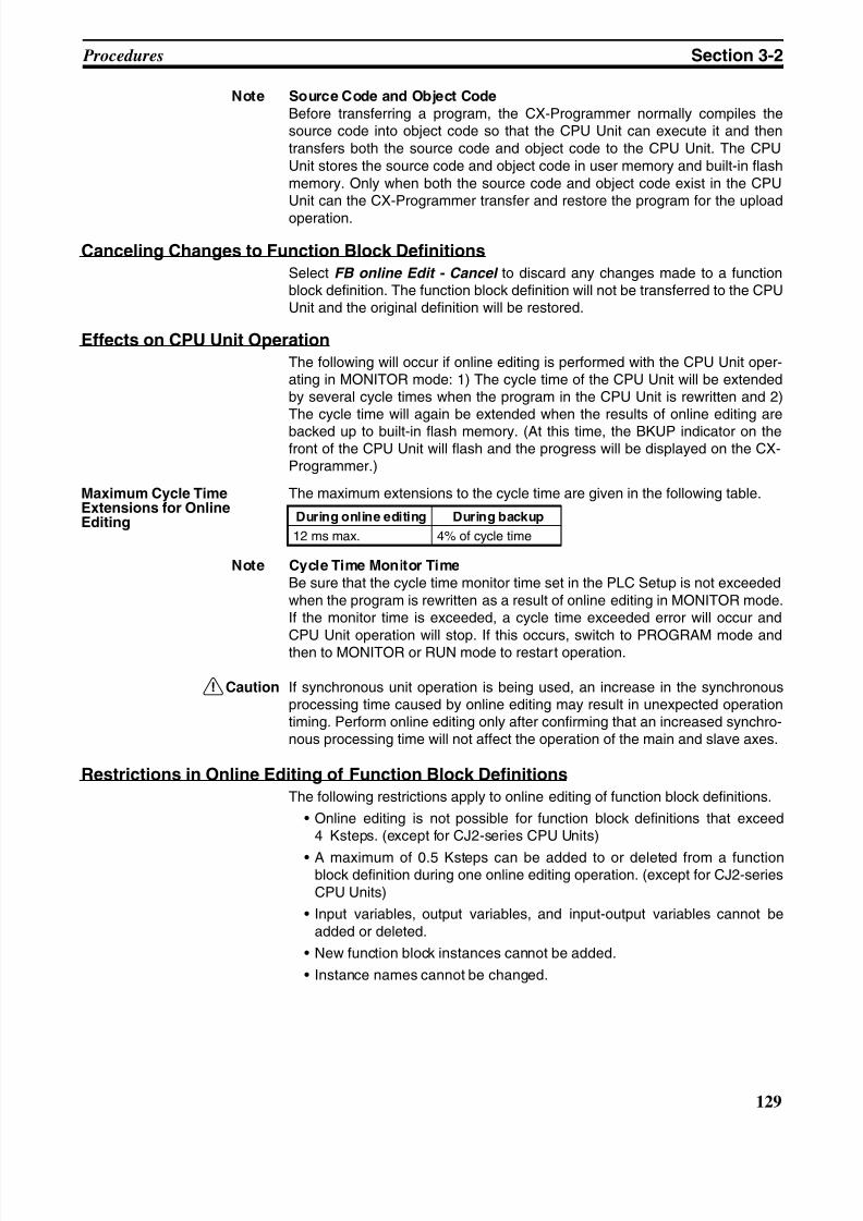
8/11/2019 CX-Programmer V9 Operation Manual FB ST.pdf
http://slidepdf.com/reader/full/cx-programmer-v9-operation-manual-fb-stpdf 155/254
129
Procedures Section 3-2
Note Source Code and Object Code
Before transferring a program, the CX-Programmer normally compiles thesource code into object code so that the CPU Unit can execute it and thentransfers both the source code and object code to the CPU Unit. The CPUUnit stores the source code and object code in user memory and built-in flashmemory. Only when both the source code and object code exist in the CPUUnit can the CX-Programmer transfer and restore the program for the upload
operation.
Canceling Changes to Function Block Definitions
Select FB online Edit - Cancel to discard any changes made to a functionblock definition. The function block definition will not be transferred to the CPUUnit and the original definition will be restored.
Effects on CPU Unit Operation
The following will occur if online editing is performed with the CPU Unit oper-ating in MONITOR mode: 1) The cycle time of the CPU Unit will be extendedby several cycle times when the program in the CPU Unit is rewritten and 2)The cycle time will again be extended when the results of online editing are
backed up to built-in flash memory. (At this time, the BKUP indicator on thefront of the CPU Unit will flash and the progress will be displayed on the CX-Programmer.)
Maximum Cycle TimeExtensions for OnlineEditing
The maximum extensions to the cycle time are given in the following table.
Note Cycle Time Monitor Time
Be sure that the cycle time monitor time set in the PLC Setup is not exceededwhen the program is rewritten as a result of online editing in MONITOR mode.If the monitor time is exceeded, a cycle time exceeded error will occur and
CPU Unit operation will stop. If this occurs, switch to PROGRAM mode andthen to MONITOR or RUN mode to restart operation.
!Caution If synchronous unit operation is being used, an increase in the synchronousprocessing time caused by online editing may result in unexpected operationtiming. Perform online editing only after confirming that an increased synchro-nous processing time will not affect the operation of the main and slave axes.
Restrictions in Online Editing of Function Block Definitions
The following restrictions apply to online editing of function block definitions.
• Online editing is not possible for function block definitions that exceed4 Ksteps. (except for CJ2-series CPU Units)
• A maximum of 0.5 Ksteps can be added to or deleted from a functionblock definition during one online editing operation. (except for CJ2-seriesCPU Units)
• Input variables, output variables, and input-output variables cannot beadded or deleted.
• New function block instances cannot be added.
• Instance names cannot be changed.
During online editing During backup
12 ms max. 4% of cycle time
8/11/2019 CX-Programmer V9 Operation Manual FB ST.pdf
http://slidepdf.com/reader/full/cx-programmer-v9-operation-manual-fb-stpdf 156/254
130
Procedures Section 3-2
• Internal variables can be added, internal variable comments can bechanged, and internal variables can be deleted from the variable table inthe function block definition. To add an internal variable, however, memorymust be reserved in advance. Refer to Editing Reserved Memory to Add
an Internal Variable with Online Editing on page 124 for details.
• The previous status flags for all differentiated instructions (DIFU(013), @instructions, DIFD(014), and % instructions) will be initialized (i.e., turnedOFF) when online editing is finished.
• After performing online editing, do not turn OFF the power supply to thePLC until the CPU Unit has finished backing up data to the built-in flashmemory (i.e., until the BKUP indicator stops flashing). If the power supplyis turned OFF before the data is backed up, the data will not be backed upand the program will return to the status it had before online editing wasperformed.
8/11/2019 CX-Programmer V9 Operation Manual FB ST.pdf
http://slidepdf.com/reader/full/cx-programmer-v9-operation-manual-fb-stpdf 157/254
Part 2:
Structured Text (ST)

8/11/2019 CX-Programmer V9 Operation Manual FB ST.pdf
http://slidepdf.com/reader/full/cx-programmer-v9-operation-manual-fb-stpdf 158/254
8/11/2019 CX-Programmer V9 Operation Manual FB ST.pdf
http://slidepdf.com/reader/full/cx-programmer-v9-operation-manual-fb-stpdf 159/254
133
SECTION 4Introduction to Structured Text
This section introduces the structure text programming functionality of the CX-Programmer and explains the features that
are not contained in the non-structured text version of CX-Programmer.
4-1 ST Language . . . . . . . . . . . . . . . . . . . . . . . . . . . . . . . . . . . . . . . . . . . . . . . . . . 134
4-1-1 Overview. . . . . . . . . . . . . . . . . . . . . . . . . . . . . . . . . . . . . . . . . . . . . . 134
4-2 CX-Programmer Specifications . . . . . . . . . . . . . . . . . . . . . . . . . . . . . . . . . . . 135
4-2-1 PLC Models Compatible with ST Programs (ST Tasks) . . . . . . . . . 135
4-2-2 Specifications . . . . . . . . . . . . . . . . . . . . . . . . . . . . . . . . . . . . . . . . . . 135
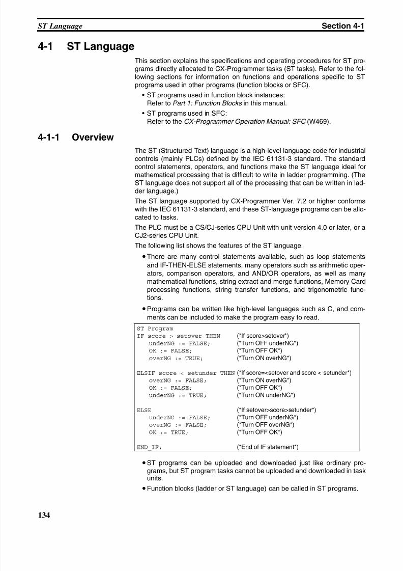
8/11/2019 CX-Programmer V9 Operation Manual FB ST.pdf
http://slidepdf.com/reader/full/cx-programmer-v9-operation-manual-fb-stpdf 160/254
134
ST Language Section 4-1
4-1 ST Language
This section explains the specifications and operating procedures for ST pro-grams directly allocated to CX-Programmer tasks (ST tasks). Refer to the fol-lowing sections for information on functions and operations specific to STprograms used in other programs (function blocks or SFC).
• ST programs used in function block instances:Refer to Part 1: Function Blocks in this manual.
• ST programs used in SFC:Refer to the CX-Programmer Operation Manual: SFC (W469).
4-1-1 Overview
The ST (Structured Text) language is a high-level language code for industrialcontrols (mainly PLCs) defined by the IEC 61131-3 standard. The standardcontrol statements, operators, and functions make the ST language ideal formathematical processing that is difficult to write in ladder programming. (TheST language does not support all of the processing that can be written in lad-der language.)
The ST language supported by CX-Programmer Ver. 7.2 or higher conformswith the IEC 61131-3 standard, and these ST-language programs can be allo-cated to tasks.
The PLC must be a CS/CJ-series CPU Unit with unit version 4.0 or later, or aCJ2-series CPU Unit.
The following list shows the features of the ST language.
•There are many control statements available, such as loop statements
and IF-THEN-ELSE statements, many operators such as arithmetic oper-ators, comparison operators, and AND/OR operators, as well as manymathematical functions, string extract and merge functions, Memory Cardprocessing functions, string transfer functions, and trigonometric func-
tions.•Programs can be written like high-level languages such as C, and com-
ments can be included to make the program easy to read.
•ST programs can be uploaded and downloaded just like ordinary pro-grams, but ST program tasks cannot be uploaded and downloaded in taskunits.
•Function blocks (ladder or ST language) can be called in ST programs.
ST Program
IF score > setover THEN (*If score>setover*)underNG := FALSE; (*Turn OFF underNG*)OK := FALSE; (*Turn OFF OK*)overNG := TRUE; (*Turn ON overNG*)
ELSIF score < setunder THEN (*If score=<setover and score < setunder*)overNG := FALSE; (*Turn ON overNG*)OK := FALSE; (*Turn OFF OK*)underNG := TRUE; (*Turn ON underNG*)
ELSE (*If setover>score>setunder*)underNG := FALSE; (*Turn OFF underNG*)overNG := FALSE; (*Turn OFF overNG*)OK := TRUE; (*Turn OFF OK*)
END_IF; (*End of IF statement*)
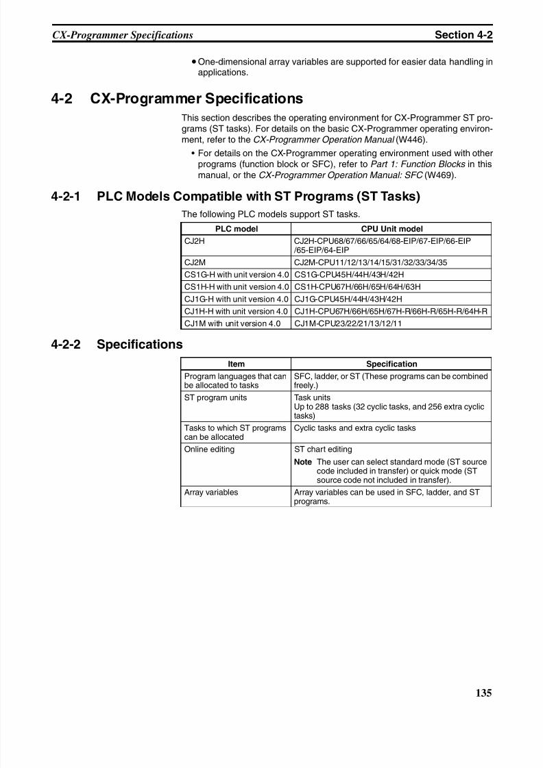
8/11/2019 CX-Programmer V9 Operation Manual FB ST.pdf
http://slidepdf.com/reader/full/cx-programmer-v9-operation-manual-fb-stpdf 161/254
135
CX-Programmer Specifications Section 4-2
•One-dimensional array variables are supported for easier data handling inapplications.
4-2 CX-Programmer Specifications
This section describes the operating environment for CX-Programmer ST pro-grams (ST tasks). For details on the basic CX-Programmer operating environ-ment, refer to the CX-Programmer Operation Manual (W446).
• For details on the CX-Programmer operating environment used with otherprograms (function block or SFC), refer to Part 1: Function Blocks in thismanual, or the CX-Programmer Operation Manual: SFC (W469).
4-2-1 PLC Models Compatible with ST Programs (ST Tasks)
The following PLC models support ST tasks.
4-2-2 Specifications
PLC model CPU Unit model
CJ2H CJ2H-CPU68/67/66/65/64/68-EIP/67-EIP/66-EIP /65-EIP/64-EIP
CJ2M CJ2M-CPU11/12/13/14/15/31/32/33/34/35
CS1G-H with unit version 4.0 CS1G-CPU45H/44H/43H/42H
CS1H-H with unit version 4.0 CS1H-CPU67H/66H/65H/64H/63H
CJ1G-H with unit version 4.0 CJ1G-CPU45H/44H/43H/42H
CJ1H-H with unit version 4.0 CJ1H-CPU67H/66H/65H/67H-R/66H-R/65H-R/64H-R
CJ1M with unit version 4.0 CJ1M-CPU23/22/21/13/12/11
Item Specification
Program languages that canbe allocated to tasks
SFC, ladder, or ST (These programs can be combinedfreely.)
ST program units Task unitsUp to 288 tasks (32 cyclic tasks, and 256 extra cyclictasks)
Tasks to which ST programscan be allocated
Cyclic tasks and extra cyclic tasks
Online editing ST chart editing
Note The user can select standard mode (ST sourcecode included in transfer) or quick mode (STsource code not included in transfer).
Array variables Array variables can be used in SFC, ladder, and STprograms.

8/11/2019 CX-Programmer V9 Operation Manual FB ST.pdf
http://slidepdf.com/reader/full/cx-programmer-v9-operation-manual-fb-stpdf 162/254
136
CX-Programmer Specifications Section 4-2
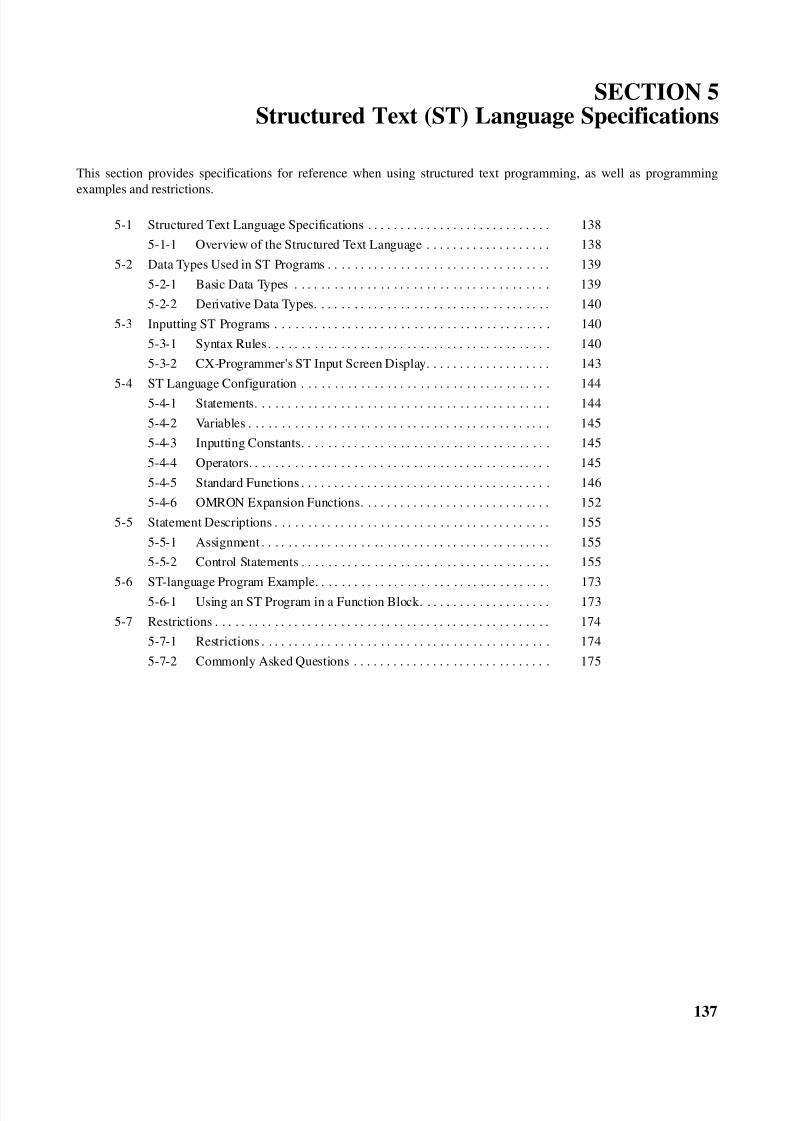
8/11/2019 CX-Programmer V9 Operation Manual FB ST.pdf
http://slidepdf.com/reader/full/cx-programmer-v9-operation-manual-fb-stpdf 163/254
137
SECTION 5Structured Text (ST) Language Specifications
This section provides specifications for reference when using structured text programming, as well as programming
examples and restrictions.
5-1 Structured Text Language Specifications . . . . . . . . . . . . . . . . . . . . . . . . . . . . 138
5-1-1 Overview of the Structured Text Language . . . . . . . . . . . . . . . . . . . 138
5-2 Data Types Used in ST Programs . . . . . . . . . . . . . . . . . . . . . . . . . . . . . . . . . . 139
5-2-1 Basic Data Types . . . . . . . . . . . . . . . . . . . . . . . . . . . . . . . . . . . . . . . 139
5-2-2 Derivative Data Types. . . . . . . . . . . . . . . . . . . . . . . . . . . . . . . . . . . . 140
5-3 Inputting ST Programs . . . . . . . . . . . . . . . . . . . . . . . . . . . . . . . . . . . . . . . . . . 140
5-3-1 Syntax Rules . . . . . . . . . . . . . . . . . . . . . . . . . . . . . . . . . . . . . . . . . . . 140
5-3-2 CX-Programmer's ST Input Screen Display. . . . . . . . . . . . . . . . . . . 143
5-4 ST Language Configuration . . . . . . . . . . . . . . . . . . . . . . . . . . . . . . . . . . . . . . 144
5-4-1 Statements. . . . . . . . . . . . . . . . . . . . . . . . . . . . . . . . . . . . . . . . . . . . . 144
5-4-2 Variables . . . . . . . . . . . . . . . . . . . . . . . . . . . . . . . . . . . . . . . . . . . . . . 145
5-4-3 Inputting Constants. . . . . . . . . . . . . . . . . . . . . . . . . . . . . . . . . . . . . . 145
5-4-4 Operators. . . . . . . . . . . . . . . . . . . . . . . . . . . . . . . . . . . . . . . . . . . . . . 145
5-4-5 Standard Functions . . . . . . . . . . . . . . . . . . . . . . . . . . . . . . . . . . . . . . 146
5-4-6 OMRON Expansion Functions. . . . . . . . . . . . . . . . . . . . . . . . . . . . . 152
5-5 Statement Descriptions . . . . . . . . . . . . . . . . . . . . . . . . . . . . . . . . . . . . . . . . . . 155
5-5-1 Assignment . . . . . . . . . . . . . . . . . . . . . . . . . . . . . . . . . . . . . . . . . . . . 155
5-5-2 Control Statements . . . . . . . . . . . . . . . . . . . . . . . . . . . . . . . . . . . . . . 155
5-6 ST-language Program Example. . . . . . . . . . . . . . . . . . . . . . . . . . . . . . . . . . . . 173
5-6-1 Using an ST Program in a Function Block. . . . . . . . . . . . . . . . . . . . 173
5-7 Restrictions . . . . . . . . . . . . . . . . . . . . . . . . . . . . . . . . . . . . . . . . . . . . . . . . . . . 174
5-7-1 Restrictions . . . . . . . . . . . . . . . . . . . . . . . . . . . . . . . . . . . . . . . . . . . . 174
5-7-2 Commonly Asked Questions . . . . . . . . . . . . . . . . . . . . . . . . . . . . . . 175
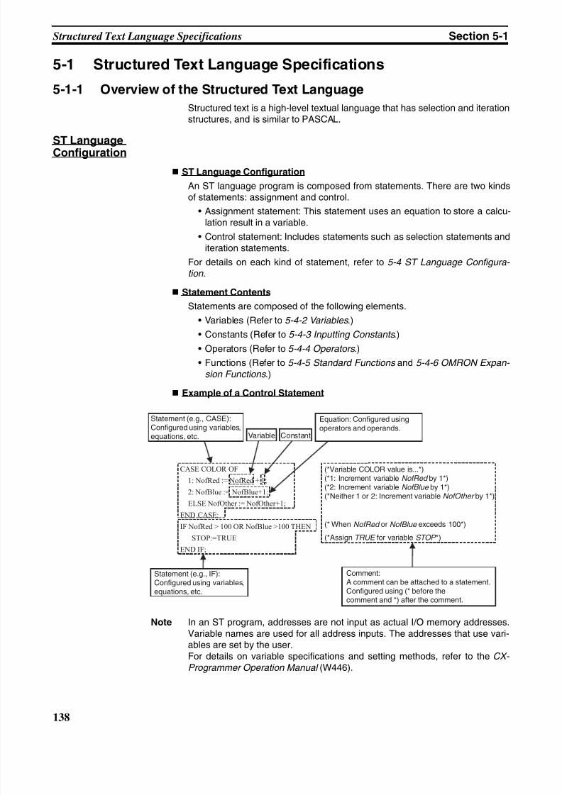
8/11/2019 CX-Programmer V9 Operation Manual FB ST.pdf
http://slidepdf.com/reader/full/cx-programmer-v9-operation-manual-fb-stpdf 164/254
138
Structured Text Language Specifications Section 5-1
5-1 Structured Text Language Specifications
5-1-1 Overview of the Structured Text Language
Structured text is a high-level textual language that has selection and iterationstructures, and is similar to PASCAL.
ST LanguageConfiguration
ST Language Configuration
An ST language program is composed from statements. There are two kindsof statements: assignment and control.
• Assignment statement: This statement uses an equation to store a calcu-lation result in a variable.
• Control statement: Includes statements such as selection statements anditeration statements.
For details on each kind of statement, refer to 5-4 ST Language Configura-
tion . Statement Contents
Statements are composed of the following elements.
• Variables (Refer to 5-4-2 Variables .)
• Constants (Refer to 5-4-3 Inputting Constants .)
• Operators (Refer to 5-4-4 Operators .)
• Functions (Refer to 5-4-5 Standard Functions and 5-4-6 OMRON Expan-
sion Functions .)
Example of a Control Statement
Note In an ST program, addresses are not input as actual I/O memory addresses.Variable names are used for all address inputs. The addresses that use vari-ables are set by the user.For details on variable specifications and setting methods, refer to the CX-
Programmer Operation Manual (W446).
CASE COLOR OF
1: NofRed := NofRed + 1;
2: NofBlue := NofBlue+1;
ELSE NofOther := NofOther+1;
END CASE;
IF NofRed > 100 OR NofBlue >100 THEN
STOP:=TRUE
END IF;
Statement (e.g., CASE):Configured using variables,equations, etc.
Equation: Configured usingoperators and operands.
(*Variable COLOR value is...*)(*1: Increment variable NofRed by 1*)(*2: Increment variable NofBlue by 1*)(*Neither 1 or 2: Increment variable NofOther by 1*)
(* When NofRed or NofBlue exceeds 100*)
(*Assign TRUE for variable STOP *)
Statement (e.g., IF):Configured using variables,equations, etc.
Comment:A comment can be attached to a statement.Configured using (* before thecomment and *) after the comment.
Variable Constant
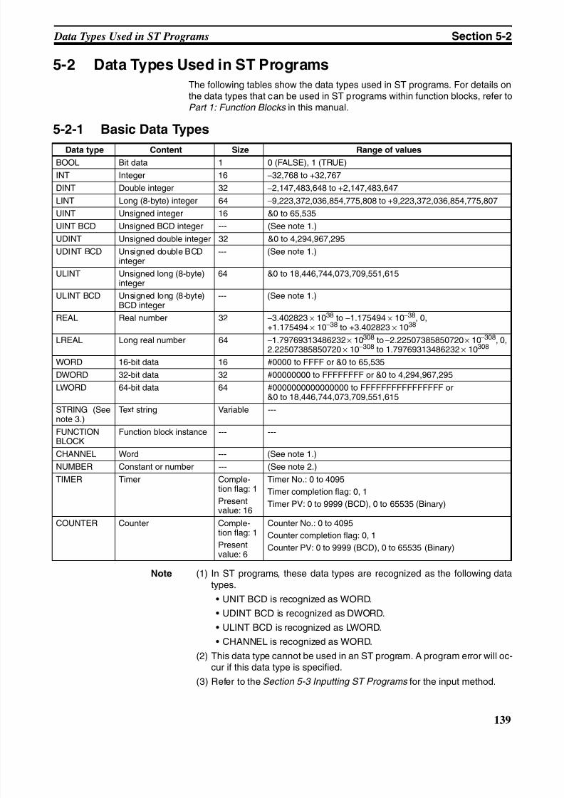
8/11/2019 CX-Programmer V9 Operation Manual FB ST.pdf
http://slidepdf.com/reader/full/cx-programmer-v9-operation-manual-fb-stpdf 165/254
139
Data Types Used in ST Programs Section 5-2
5-2 Data Types Used in ST Programs
The following tables show the data types used in ST programs. For details onthe data types that can be used in ST programs within function blocks, refer toPart 1: Function Blocks in this manual.
5-2-1 Basic Data Types
Note (1) In ST programs, these data types are recognized as the following datatypes.
• UNIT BCD is recognized as WORD.
• UDINT BCD is recognized as DWORD.
• ULINT BCD is recognized as LWORD.
• CHANNEL is recognized as WORD.
(2) This data type cannot be used in an ST program. A program error will oc-cur if this data type is specified.
(3) Refer to the Section 5-3 Inputting ST Programs for the input method.
Data type Content Size Range of values
BOOL Bit data 1 0 (FALSE), 1 (TRUE)
INT Integer 16 −32,768 to +32,767
DINT Double integer 32 −2,147,483,648 to +2,147,483,647
LINT Long (8-byte) integer 64 −9,223,372,036,854,775,808 to +9,223,372,036,854,775,807
UINT Unsigned integer 16 &0 to 65,535
UINT BCD Unsigned BCD integer --- (See note 1.)
UDINT Unsigned double integer 32 &0 to 4,294,967,295
UDINT BCD Unsigned double BCDinteger
--- (See note 1.)
ULINT Unsigned long (8-byte)integer
64 &0 to 18,446,744,073,709,551,615
ULINT BCD Unsigned long (8-byte)BCD integer
--- (See note 1.)
REAL Real number 32 −3.402823 × 1038 to −1.175494 × 10−38, 0,+1.175494 × 10−38 to +3.402823 × 1038
LREAL Long real number 64 −1.79769313486232 × 10308 to−2.22507385850720 × 10−308, 0,2.22507385850720 × 10−308 to 1.79769313486232 × 10308
WORD 16-bit data 16 #0000 to FFFF or &0 to 65,535
DWORD 32-bit data 32 #00000000 to FFFFFFFF or &0 to 4,294,967,295
LWORD 64-bit data 64 #0000000000000000 to FFFFFFFFFFFFFFFF or&0 to 18,446,744,073,709,551,615
STRING (See
note 3.)
Text string Variable ---
FUNCTIONBLOCK
Function block instance --- ---
CHANNEL Word --- (See note 1.)
NUMBER Constant or number --- (See note 2.)
TIMER Timer Comple-tion flag: 1
Presentvalue: 16
Timer No.: 0 to 4095
Timer completion flag: 0, 1
Timer PV: 0 to 9999 (BCD), 0 to 65535 (Binary)
COUNTER Counter Comple-tion flag: 1
Presentvalue: 6
Counter No.: 0 to 4095
Counter completion flag: 0, 1
Counter PV: 0 to 9999 (BCD), 0 to 65535 (Binary)
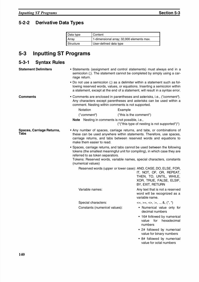
8/11/2019 CX-Programmer V9 Operation Manual FB ST.pdf
http://slidepdf.com/reader/full/cx-programmer-v9-operation-manual-fb-stpdf 166/254
140
Inputting ST Programs Section 5-3
5-2-2 Derivative Data Types
5-3 Inputting ST Programs
5-3-1 Syntax Rules
Statement Delimiters • Statements (assignment and control statements) must always end in asemicolon (;). The statement cannot be completed by simply using a car-riage return.
• Do not use a semicolon (;) as a delimiter within a statement such as fol-lowing reserved words, values, or equations. Inserting a semicolon withina statement, except at the end of a statement, will result in a syntax error.
Comments • Comments are enclosed in parentheses and asterisks, i.e., (*comment* ).Any characters except parentheses and asterisks can be used within acomment. Nesting within comments is not supported.
Notation Example
(*comment* ) (*this is the comment*)
Note Nesting in comments is not possible, i.e.,(*(*this type of nesting is not supported*)*)
Spaces, Carriage Returns,Tabs
• Any number of spaces, carriage returns, and tabs, or combinations ofthese can be used anywhere within statements. Therefore, use spaces,carriage returns, and tabs between reserved words and equations tomake them easier to read.
• Spaces, carriage returns, and tabs cannot be used between the followingtokens (the smallest meaningful unit for compiling), in which case they arereferred to as token separators.Tokens: Reserved words, variable names, special characters, constants(numerical values)
Reserved words (upper or lower case): AND, CASE, DO, ELSE, FOR,IT, NOT, OF, OR, REPEAT,THEN, TO, UNTIL, WHILE,XOR, TRUE, FALSE, ELSIF,BY, EXIT, RETURN
Variable names: Any text that is not a reservedword will be recognized as a
variable name.Special characters: <=, >=, <>, :=, .., &, (*, *)
Constants (numerical values): • Numerical value only fordecimal numbers
• 16# followed by numericalvalue for hexadecimalnumbers
• 2# followed by numericalvalue for binary numbers
• 8# followed by numericalvalue for octal numbers
Data type Content
Array 1-dimensional array; 32,000 elements max.
Structure User-defined data type
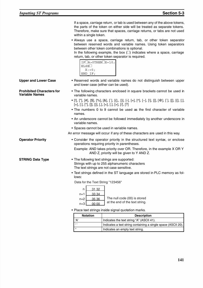
8/11/2019 CX-Programmer V9 Operation Manual FB ST.pdf
http://slidepdf.com/reader/full/cx-programmer-v9-operation-manual-fb-stpdf 167/254
141
Inputting ST Programs Section 5-3
If a space, carriage return, or tab is used between any of the above tokens,the parts of the token on either side will be treated as separate tokens.Therefore, make sure that spaces, carriage returns, or tabs are not usedwithin a single token.
• Always use a space, carriage return, tab, or other token separatorbetween reserved words and variable names. Using token separatorsbetween other token combinations is optional.In the following example, the box (@) indicates where a space, carriagereturn, tab, or other token separator is required.
Upper and Lower Case • Reserved words and variable names do not distinguish between upperand lower case (either can be used).
Prohibited Characters forVariable Names
• The following characters enclosed in square brackets cannot be used invariable names.
• [!], ["], [#], [$], [%], [&], [`], [(],, [)], [-], [=], [^], [~], [\], [|], [@], [`], [[], [{], [;],[+], [:], [*], []], [}], [,], [<], [.], [>], [/], [?]
• The numbers 0 to 9 cannot be used as the first character of variablenames.
• An underscore cannot be followed immediately by another underscore invariable names.
• Spaces cannot be used in variable names.
An error message will occur if any of these characters are used in this way.
Operator Priority • Consider the operator priority in the structured text syntax, or encloseoperations requiring priority in parentheses.
Example: AND takes priority over OR. Therefore, in the example X OR YAND Z, priority will be given to Y AND Z.
STRING Data Type • The following text strings are supported:Strings with up to 255 alphanumeric charactersThe text strings are not case sensitive.
• Text strings defined in the ST language are stored in PLC memory as fol-lows:
• Place text strings inside signal quotation marks.
IF@ A>0THEN@X=10;ELSE@ X:=0;END_IF;
Notation Description
‘A’ Indicates the text string “A” (ASCII 41).
‘ ’ Indicates a text string containing a single space (ASCII 20).
‘’ Indicates an empty text string.
n
n+1
31 32
33 34
35 36
00 00
n+2
n+3
Data for the Text String "123456"
The null code (00) is stored
at the end of the text string.
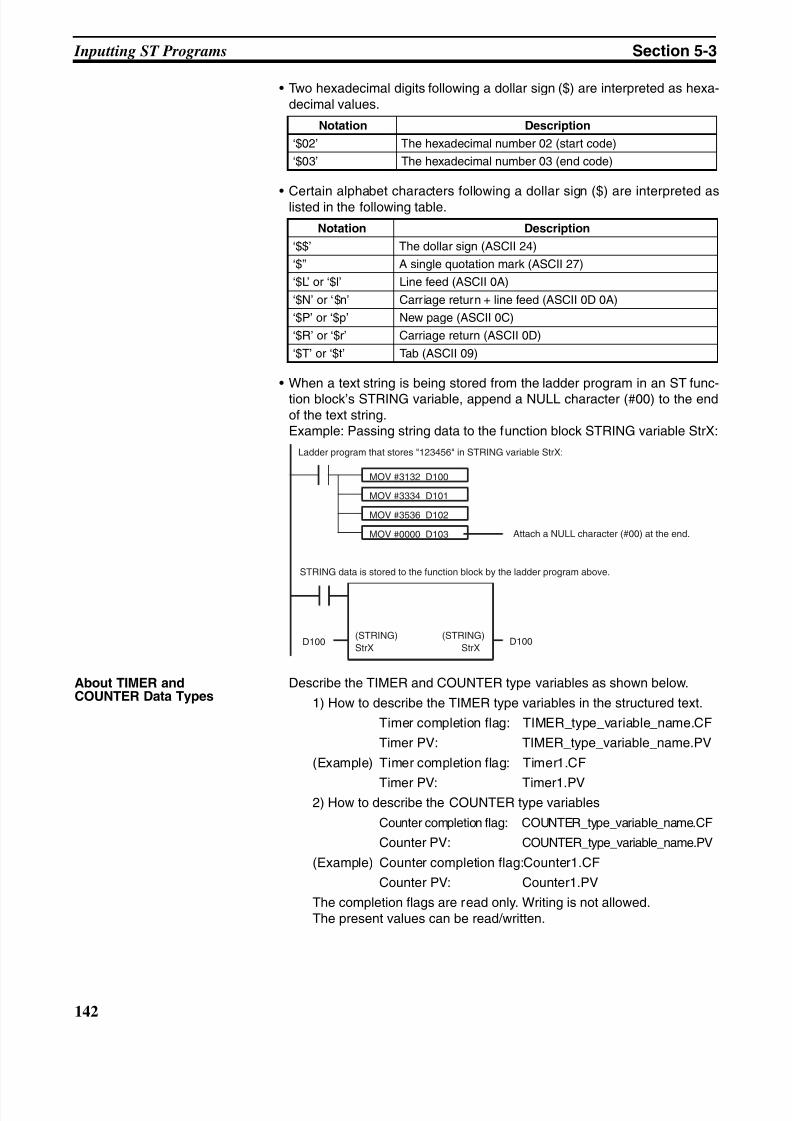
8/11/2019 CX-Programmer V9 Operation Manual FB ST.pdf
http://slidepdf.com/reader/full/cx-programmer-v9-operation-manual-fb-stpdf 168/254
142
Inputting ST Programs Section 5-3
• Two hexadecimal digits following a dollar sign ($) are interpreted as hexa-decimal values.
• Certain alphabet characters following a dollar sign ($) are interpreted aslisted in the following table.
• When a text string is being stored from the ladder program in an ST func-tion block’s STRING variable, append a NULL character (#00) to the endof the text string.Example: Passing string data to the function block STRING variable StrX:
About TIMER andCOUNTER Data Types
Describe the TIMER and COUNTER type variables as shown below.
1) How to describe the TIMER type variables in the structured text.
Timer completion flag: TIMER_type_variable_name.CF
Timer PV: TIMER_type_variable_name.PV
(Example) Timer completion flag: Timer1.CF
Timer PV: Timer1.PV2) How to describe the COUNTER type variables
Counter completion flag: COUNTER_type_variable_name.CF
Counter PV: COUNTER_type_variable_name.PV
(Example) Counter completion flag:Counter1.CF
Counter PV: Counter1.PV
The completion flags are read only. Writing is not allowed.The present values can be read/written.
Notation Description
‘$02’ The hexadecimal number 02 (start code)
‘$03’ The hexadecimal number 03 (end code)
Notation Description
‘$$’ The dollar sign (ASCII 24)
‘$’’ A single quotation mark (ASCII 27)
‘$L’ or ‘$l’ Line feed (ASCII 0A)
‘$N’ or ‘$n’ Carriage return + line feed (ASCII 0D 0A)
‘$P’ or ‘$p’ New page (ASCII 0C)
‘$R’ or ‘$r’ Carriage return (ASCII 0D)
‘$T’ or ‘$t’ Tab (ASCII 09)
Ladder program that stores "123456" in STRING variable StrX:
MOV #3132 D100
MOV #3334 D101
MOV #3536 D102
MOV #0000 D103
STRING data is stored to the function block by the ladder program above.
(STRING)
StrX
(STRING)
StrXD100 D100
Attach a NULL character (#00) at the end.
8/11/2019 CX-Programmer V9 Operation Manual FB ST.pdf
http://slidepdf.com/reader/full/cx-programmer-v9-operation-manual-fb-stpdf 169/254
143
Inputting ST Programs Section 5-3
5-3-2 CX-Programmer's ST Input Screen Display
Text Display Color The CX-Programmer automatically displays text in the following colors when itis input or pasted in the ST Input Screen.
• Text keywords (reserved words): Blue
• Comments: Green
• Errors: Red
• Other: Black
Changing Fonts To change font sizes or display colors, select Tools - Options , click theAppearance Tab, and then click the ST Font Button. The font name, font size(default is 8 point), and color can be changed.
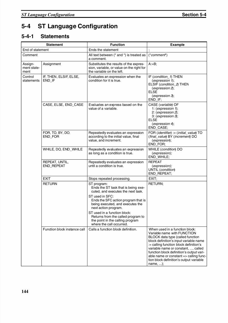
8/11/2019 CX-Programmer V9 Operation Manual FB ST.pdf
http://slidepdf.com/reader/full/cx-programmer-v9-operation-manual-fb-stpdf 170/254
144
ST Language Configuration Section 5-4
5-4 ST Language Configuration
5-4-1 Statements
Statement Function Example
End of statement Ends the statement ;
Comment All text between (* and *) is treated asa comment. (*comment *)
Assign-ment state-ment
Assignment Substitutes the results of the expres-sion, variable, or value on the right forthe variable on the left.
A:=B;
Controlstatements
IF, THEN, ELSIF, ELSE,END_IF
Evaluates an expression when thecondition for it is true.
IF (condition_1) THEN(expression 1);
ELSIF (condition_2 ) THEN(expression 2 );
ELSE(expression 3 );
END_IF;
CASE, ELSE, END_CASE Evaluates an express based on thevalue of a variable.
CASE (variable ) OF1: (expression 1);
2: (expression 2 );3: (expression 3 );ELSE
(expression 4 );END_CASE;
FOR, TO, BY, DO,END_FOR
Repeatedly evaluates an expressionaccording to the initial value, finalvalue, and increment.
FOR (identifier ) := (initial_value ) TO(final_value ) BY (increment ) DO
(expression );END_FOR;
WHILE, DO, END_WHILE Repeatedly evaluates an expressionas long as a condition is true.
WHILE (condition ) DO(expression);
END_WHILE;
REPEAT, UNTIL,END_REPEAT
Repeatedly evaluates an expressionuntil a condition is true.
REPEAT(expression);
UNTIL (condition )END_REPEAT;
EXIT Stops repeated processing. EXIT;
RETURN ST program:Ends the ST task that is being exe-cuted, and executes the next task.
ST used in SFC:Ends the SFC action program that isbeing executed, and executes thenext action program.
ST used in a function block:Returns from the called program tothe point in the calling programwhere the call occurred.
RETURN;
Function block instance call Calls a function block definition. When used in a function block:Variable name with FUNCTIONBLOCK data type (called functionblock definition’s input variable name:= calling function block definition’svariable name or constant, ..., calledfunction block definition’s output vari-able name or constant => calling func-tion block definition’s output variablename, ...);
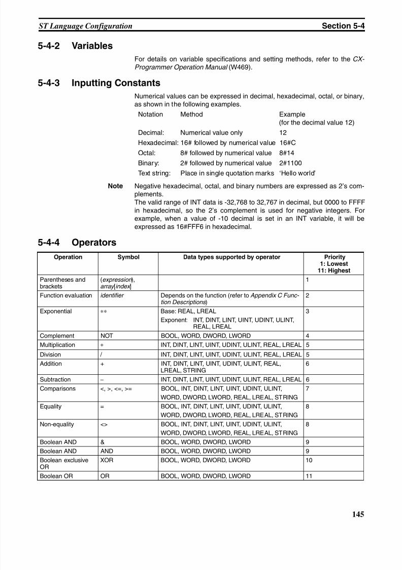
8/11/2019 CX-Programmer V9 Operation Manual FB ST.pdf
http://slidepdf.com/reader/full/cx-programmer-v9-operation-manual-fb-stpdf 171/254
145
ST Language Configuration Section 5-4
5-4-2 Variables
For details on variable specifications and setting methods, refer to the CX- Programmer Operation Manual (W469).
5-4-3 Inputting Constants
Numerical values can be expressed in decimal, hexadecimal, octal, or binary,as shown in the following examples.
Notation Method Example(for the decimal value 12)
Decimal: Numerical value only 12
Hexadecimal: 16# followed by numerical value 16#C
Octal: 8# followed by numerical value 8#14
Binary: 2# followed by numerical value 2#1100
Text string: Place in single quotation marks ‘Hello world’
Note Negative hexadecimal, octal, and binary numbers are expressed as 2’s com-plements.
The valid range of INT data is -32,768 to 32,767 in decimal, but 0000 to FFFFin hexadecimal, so the 2’s complement is used for negative integers. Forexample, when a value of -10 decimal is set in an INT variable, it will beexpressed as 16#FFF6 in hexadecimal.
5-4-4 Operators
Operation Symbol Data types supported by operator Priority1: Lowest
11: Highest
Parentheses andbrackets
(expression ),array [index ]
1
Function evaluation identifier Depends on the function (refer to Appendix C Func- tion Descriptions )
2
Exponential ∗∗ Base: REAL, LREAL
Exponent: INT, DINT, LINT, UINT, UDINT, ULINT,REAL, LREAL
3
Complement NOT BOOL, WORD, DWORD, LWORD 4
Multiplication ∗ INT, DINT, LINT, UINT, UDINT, ULINT, REAL, LREAL 5
Division / INT, DINT, LINT, UINT, UDINT, ULINT, REAL, LREAL 5
Addition + INT, DINT, LINT, UINT, UDINT, ULINT, REAL,LREAL, STRING
6
Subtraction − INT, DINT, LINT, UINT, UDINT, ULINT, REAL, LREAL 6
Comparisons <, >, <=, >= BOOL, INT, DINT, LINT, UINT, UDINT, ULINT,
WORD, DWORD, LWORD, REAL, LREAL, STRING
7
Equality = BOOL, INT, DINT, LINT, UINT, UDINT, ULINT,
WORD, DWORD, LWORD, REAL, LREAL, STRING
8
Non-equality <> BOOL, INT, DINT, LINT, UINT, UDINT, ULINT,
WORD, DWORD, LWORD, REAL, LREAL, STRING
8
Boolean AND & BOOL, WORD, DWORD, LWORD 9
Boolean AND AND BOOL, WORD, DWORD, LWORD 9
Boolean exclusiveOR
XOR BOOL, WORD, DWORD, LWORD 10
Boolean OR OR BOOL, WORD, DWORD, LWORD 11
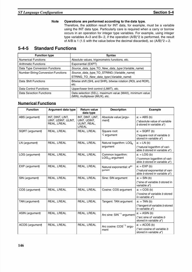
8/11/2019 CX-Programmer V9 Operation Manual FB ST.pdf
http://slidepdf.com/reader/full/cx-programmer-v9-operation-manual-fb-stpdf 172/254
146
ST Language Configuration Section 5-4
Note Operations are performed according to the data type.
Therefore, the addition result for INT data, for example, must be a variableusing the INT data type. Particularly care is required when a carry or borrowoccurs in an operation for integer type variables. For example, using integertype variables A=3 and B= 2, if the operation (A/B)*2 is performed, the resultof A/B is 1 (1.5 with the value below the decimal discarded), so (A/B)*2 = 2.
5-4-5 Standard Functions
Numerical Functions
Function type Syntax
Numerical Functions Absolute values, trigonometric functions, etc.
Arithmetic Functions Exponential (EXPT)
Data Type Conversion Functions Source_data_type _TO_New_data_type (Variable_name )
Number-String Conversion Functions Source_data_type _TO_STRING (Variable _name )
STRING_TO_New_data_type (Variable _name )
Data Shift Functions Bitwise shift (SHL and SHR), bitwise rotation (ROL and ROR),etc.
Data Control Functions Upper/lower limit control (LIMIT), etc.
Data Selection Functions Data selection (SEL), maximum value (MAX), minimum value(MIN), multiplexer (MUX), etc.
Function Argument data type Return valuedata type
Description Example
ABS (argument ) INT, DINT, LINT,UINT, UDINT, ULINT,REAL, LREAL
INT, DINT, LINT,UINT, UDINT,ULINT, REAL,LREAL
Absolute value [argu- ment ]
a: = ABS (b)
(*absolute value of variableb stored in variable a *)
SQRT (argument ) REAL, LREAL REAL, LREAL Square root:
√ argument
a: = SQRT (b)
(*square root of variable bstored in variable a *)
LN (argument ) REAL, LREAL REAL, LREAL Natural logarithm: LOGe argument
a: = LN (b)(*natural logarithm of vari-able b stored in variable a *)
LOG (argument ) REAL, LREAL REAL, LREAL Common logarithm:LOG10 argument
a: = LOG (b)
(*common logarithm of vari-able b stored in variable a *)
EXP (argument ) REAL, LREAL REAL, LREAL Natural exponential: ear-
gument
a: = EXP (b)
(*natural exponential of vari-able b stored in variable a *)
SIN (argument ) REAL, LREAL REAL, LREAL Sine: SIN argument a: = SIN (b)
(*sine of variable b stored invariable a *)
COS (argument ) REAL, LREAL REAL, LREAL Cosine: COS argument a: = COS (b)(*cosine of variable b storedin variable a *)
TAN (argument ) REAL, LREAL REAL, LREAL Tangent: TAN argument a: = TAN (b)
(*tangent of variable b storedin variable a *)
ASIN (argument ) REAL, LREAL REAL, LREALArc sine: SIN
−1 argumenta: = ASIN (b)
(*arc sine of variable bstored in variable a *)
ACOS (argument ) REAL, LREAL REAL, LREALArc cosine: COS
−1 argu-ment
a: = ACOS (b)
(*arc cosine of variable bstored in variable a *)
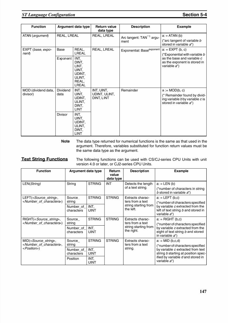
8/11/2019 CX-Programmer V9 Operation Manual FB ST.pdf
http://slidepdf.com/reader/full/cx-programmer-v9-operation-manual-fb-stpdf 173/254
147
ST Language Configuration Section 5-4
Note The data type returned for numerical functions is the same as that used in theargument. Therefore, variables substituted for function return values must bethe same data type as the argument.
Text String Functions The following functions can be used with CS/CJ-series CPU Units with unitversion 4.0 or later, or CJ2-series CPU Units.
ATAN (argument ) REAL, LREAL REAL, LREALArc tangent: TAN
−1 argu-ment
a: = ATAN (b)
(*arc tangent of variable bstored in variable a *)
EXPT (base, expo- nent )
Base REAL,LREAL
REAL, LREAL Exponential: Baseexponent a: = EXPT (b, c)
(*Exponential with variable b as the base and variable c as the exponent is stored invariable a *)
Exponent INT,DINT,LINT,UINT,UDINT,ULINT,REAL,LREAL
MOD (dividend data,divisor)
Dividenddata
INT,UINT,UDINT,ULINT,DINT,LINT
INT, UINT,UDINT, ULINT,DINT, LINT
Remainder a := MOD(b, c)
(* Remainder found by divid-ing variable b by variable c isstored in variable a *)
Divisor INT,UINT,UDINT,ULINT,DINT,LINT
Function Argument data type Return valuedata type
Description Example
Function Argument data type Returnvalue
data type
Description Example
LEN(String) String STRING INT Detects the lengthof a text string.
a: = LEN (b)
(*number of characters in stringb stored in variable a *)
LEFT(<Source_string >,<Number_of_characters >)
Source_string
STRING STRING Extracts charac-ters from a textstring starting fromthe left.
a: = LEFT (b,c)
(*number of characters specifiedby variable c extracted from theleft of text string b and stored invariable a *)
Number_of_characters
INT,UINT
RIGHT(<Source_string >,<Number_of_characters >)
Source_string
STRING STRING Extracts charac-ters from a text
string starting fromthe right.
a: = RIGHT (b,c)
(*number of characters specifiedby variable c extracted from theeight of text string b and storedin variable a *)
Number_of_characters
INT,UINT
MID(<Source_string >,<Number_of_characters >,<Position >)
Source_string
STRING STRING Extracts charac-ters from a textstring.
a: = MID (b,c,d)
(*number of characters specifiedby variable c extracted from textstring b starting at position spec-ified by variable d and stored invariable a *)
Number_of_characters
INT,UINT
Position INT,UINT
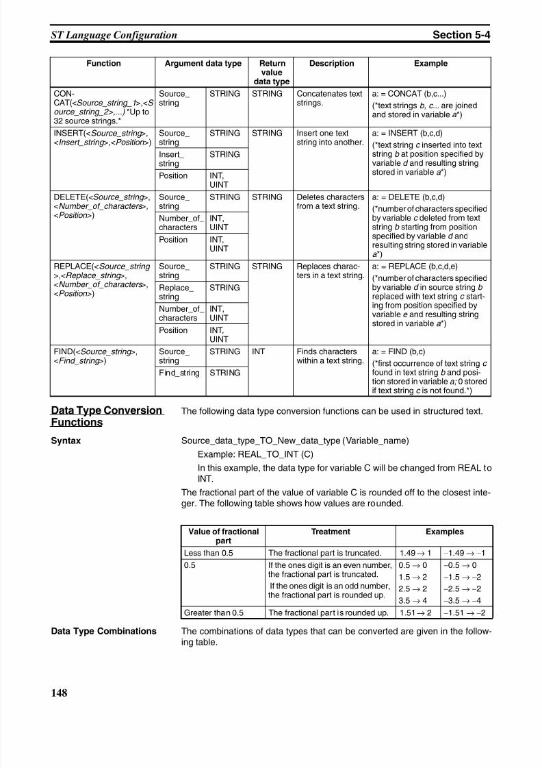
8/11/2019 CX-Programmer V9 Operation Manual FB ST.pdf
http://slidepdf.com/reader/full/cx-programmer-v9-operation-manual-fb-stpdf 174/254
148
ST Language Configuration Section 5-4
Data Type ConversionFunctions
The following data type conversion functions can be used in structured text.
Syntax Source_data_type_TO_New_data_type (Variable_name)
Example: REAL_TO_INT (C)
In this example, the data type for variable C will be changed from REAL toINT.
The fractional part of the value of variable C is rounded off to the closest inte-ger. The following table shows how values are rounded.
Data Type Combinations The combinations of data types that can be converted are given in the follow-ing table.
CON-CAT(<Source_string_1>,<S ource_string_2>,...) *Up to32 source strings.*
Source_string
STRING STRING Concatenates textstrings.
a: = CONCAT (b,c...)
(*text strings b, c... are joinedand stored in variable a *)
INSERT(<Source_string >,<Insert_string >,<Position >) Source_string STRING STRING Insert one textstring into another. a: = INSERT (b,c,d)(*text string c inserted into textstring b at position specified byvariable d and resulting stringstored in variable a *)
Insert_string
STRING
Position INT,UINT
DELETE(<Source_string >,<Number_of_characters >,<Position >)
Source_string
STRING STRING Deletes charactersfrom a text string.
a: = DELETE (b,c,d)
(*number of characters specifiedby variable c deleted from textstring b starting from positionspecified by variable d andresulting string stored in variablea *)
Number_of_characters
INT,UINT
Position INT,UINT
REPLACE(<Source_string >,<Replace_string >,<Number_of_characters >,<Position >)
Source_string STRING STRING Replaces charac-ters in a text string. a: = REPLACE (b,c,d,e)(*number of characters specifiedby variable d in source string b replaced with text string c start-ing from position specified byvariable e and resulting string stored in variable a *)
Replace_string
STRING
Number_of_characters
INT,UINT
Position INT,UINT
FIND(<Source_string >,<Find_string >)
Source_string
STRING INT Finds characterswithin a text string.
a: = FIND (b,c)
(*first occurrence of text string c found in text string b and posi-tion stored in variable a; 0 storedif text string c is not found.*)
Find_string STRING
Function Argument data type Returnvalue
data type
Description Example
Value of fractional
part
Treatment Examples
Less than 0.5 The fractional part is truncated. 1.49 → 1 −1.49 → −1
0.5 If the ones digit is an even number,the fractional part is truncated.
If the ones digit is an odd number,the fractional part is rounded up.
0.5 → 0
1.5 → 2
2.5 → 2
3.5 → 4
−0.5 → 0
−1.5 → −2
−2.5 → −2
−3.5 → −4
Greater than 0.5 The fractional part is rounded up. 1.51 → 2 −1.51 → −2
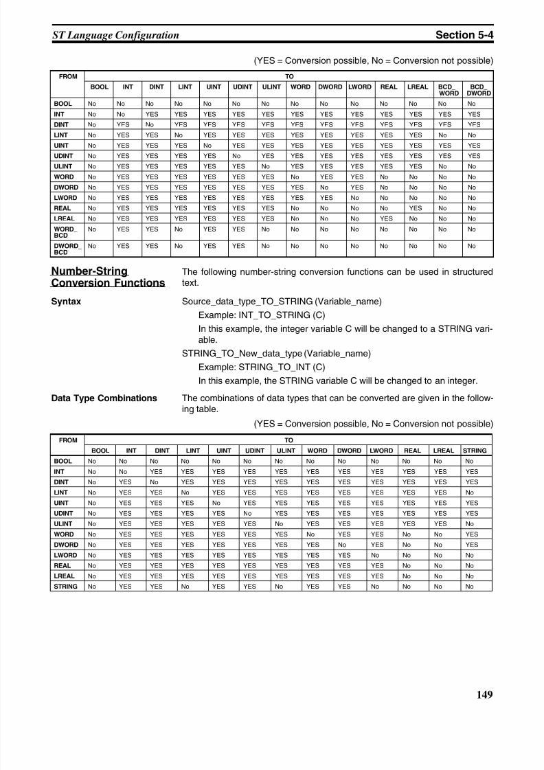
8/11/2019 CX-Programmer V9 Operation Manual FB ST.pdf
http://slidepdf.com/reader/full/cx-programmer-v9-operation-manual-fb-stpdf 175/254
149
ST Language Configuration Section 5-4
(YES = Conversion possible, No = Conversion not possible)
Number-StringConversion Functions
The following number-string conversion functions can be used in structuredtext.
Syntax Source_data_type_TO_STRING (Variable_name)
Example: INT_TO_STRING (C)
In this example, the integer variable C will be changed to a STRING vari-able.
STRING_TO_New_data_type (Variable_name)
Example: STRING_TO_INT (C)
In this example, the STRING variable C will be changed to an integer.
Data Type Combinations The combinations of data types that can be converted are given in the follow-ing table.
(YES = Conversion possible, No = Conversion not possible)
FROM TO
BOOL INT DINT LINT UINT UDINT ULINT WORD DWORD LWORD REAL LREAL BCD_WORD
BCD_DWORD
BOOL No No No No No No No No No No No No No No
INT No No YES YES YES YES YES YES YES YES YES YES YES YES
DINT No YES No YES YES YES YES YES YES YES YES YES YES YES
LINT No YES YES No YES YES YES YES YES YES YES YES No NoUINT No YES YES YES No YES YES YES YES YES YES YES YES YES
UDINT No YES YES YES YES No YES YES YES YES YES YES YES YES
ULINT No YES YES YES YES YES No YES YES YES YES YES No No
WORD No YES YES YES YES YES YES No YES YES No No No No
DWORD No YES YES YES YES YES YES YES No YES No No No No
LWORD No YES YES YES YES YES YES YES YES No No No No No
REAL No YES YES YES YES YES YES No No No No YES No No
LREAL No YES YES YES YES YES YES No No No YES No No No
WORD_BCD
No YES YES No YES YES No No No No No No No No
DWORD_BCD
No YES YES No YES YES No No No No No No No No
FROM TO
BOOL INT DINT LINT UINT UDINT ULINT WORD DWORD LWORD REAL LREAL STRING
BOOL No No No No No No No No No No No No No
INT No No YES YES YES YES YES YES YES YES YES YES YES
DINT No YES No YES YES YES YES YES YES YES YES YES YES
LINT No YES YES No YES YES YES YES YES YES YES YES No
UINT No YES YES YES No YES YES YES YES YES YES YES YES
UDINT No YES YES YES YES No YES YES YES YES YES YES YES
ULINT No YES YES YES YES YES No YES YES YES YES YES No
WORD No YES YES YES YES YES YES No YES YES No No YES
DWORD No YES YES YES YES YES YES YES No YES No No YES
LWORD No YES YES YES YES YES YES YES YES No No No No
REAL No YES YES YES YES YES YES YES YES YES No No No
LREAL No YES YES YES YES YES YES YES YES YES No No No
STRING No YES YES No YES YES No YES YES No No No No
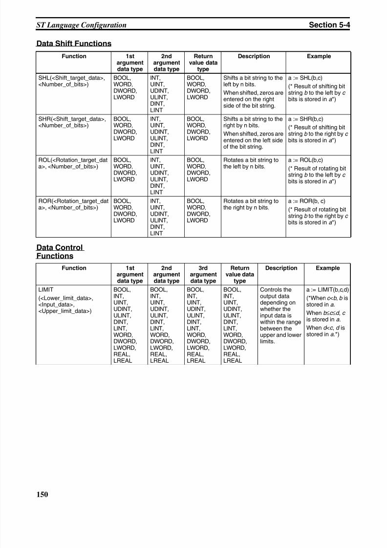
8/11/2019 CX-Programmer V9 Operation Manual FB ST.pdf
http://slidepdf.com/reader/full/cx-programmer-v9-operation-manual-fb-stpdf 176/254
150
ST Language Configuration Section 5-4
Data Shift Functions
Data ControlFunctions
Function 1stargumentdata type
2ndargumentdata type
Returnvalue data
type
Description Example
SHL(<Shift_target_data>,<Number_of_bits>)
BOOL,WORD,DWORD,
LWORD
INT,UINT,UDINT,
ULINT,DINT,LINT
BOOL,WORD,DWORD,
LWORD
Shifts a bit string to theleft by n bits.
When shifted, zeros areentered on the rightside of the bit string.
a := SHL(b,c)
(* Result of shifting bit
stringb to the left by
c bits is stored in a *)
SHR(<Shift_target_data>,<Number_of_bits>)
BOOL,WORD,DWORD,LWORD
INT,UINT,UDINT,ULINT,DINT,LINT
BOOL,WORD,DWORD,LWORD
Shifts a bit string to theright by n bits.
When shifted, zeros areentered on the left sideof the bit string.
a := SHR(b,c)
(* Result of shifting bitstring b to the right by c bits is stored in a *)
ROL(<Rotation_target_data>, <Number_of_bits>)
BOOL,WORD,DWORD,LWORD
INT,UINT,UDINT,ULINT,DINT,
LINT
BOOL,WORD,DWORD,LWORD
Rotates a bit string tothe left by n bits.
a := ROL(b,c)
(* Result of rotating bitstring b to the left by c bits is stored in a *)
ROR(<Rotation_target_data>, <Number_of_bits>)
BOOL,WORD,DWORD,LWORD
INT,UINT,UDINT,ULINT,DINT,LINT
BOOL,WORD,DWORD,LWORD
Rotates a bit string tothe right by n bits.
a := ROR(b, c)
(* Result of rotating bitstring b to the right by cbits is stored in a *)
Function 1stargumentdata type
2ndargumentdata type
3rdargumentdata type
Returnvalue data
type
Description Example
LIMIT
(<Lower_limit_data>,<Input_data>,<Upper_limit_data>)
BOOL,INT,UINT,UDINT,ULINT,DINT,LINT,WORD,DWORD,LWORD,REAL,LREAL
BOOL,INT,UINT,UDINT,ULINT,DINT,LINT,WORD,DWORD,LWORD,REAL,LREAL
BOOL,INT,UINT,UDINT,ULINT,DINT,LINT,WORD,DWORD,LWORD,REAL,LREAL
BOOL,INT,UINT,UDINT,ULINT,DINT,LINT,WORD,DWORD,LWORD,REAL,LREAL
Controls theoutput datadepending onwhether theinput data iswithin the rangebetween theupper and lowerlimits.
a := LIMIT(b,c,d)(*When c <b , b isstored in a .
When b ≤c ≤d , c is stored in a .
When d <c , d isstored in a .*)
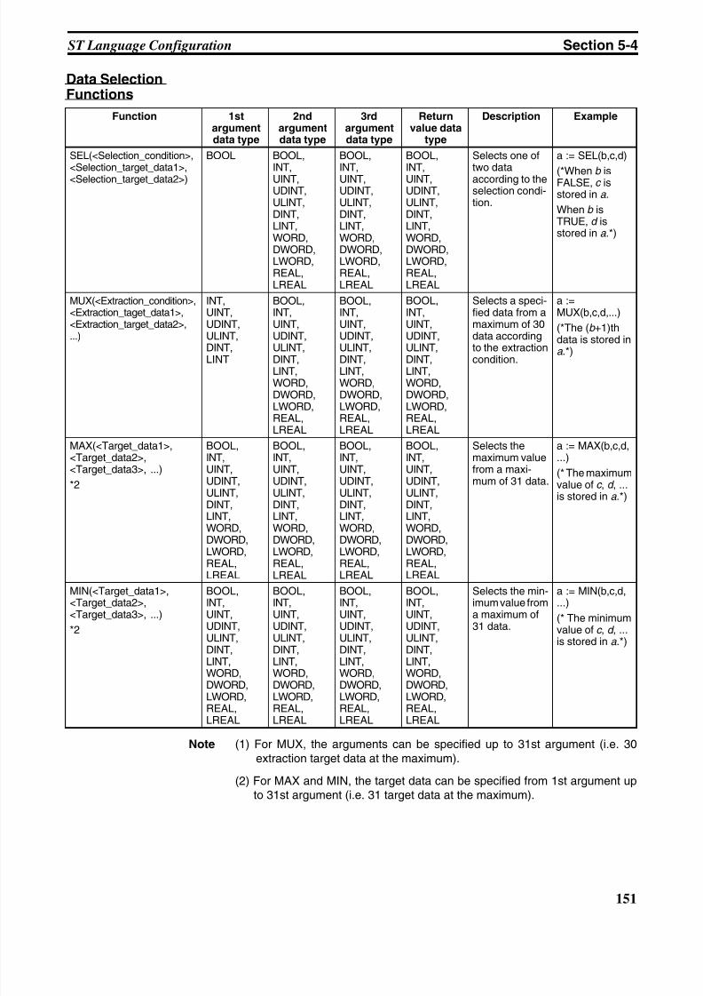
8/11/2019 CX-Programmer V9 Operation Manual FB ST.pdf
http://slidepdf.com/reader/full/cx-programmer-v9-operation-manual-fb-stpdf 177/254
151
ST Language Configuration Section 5-4
Data SelectionFunctions
Note (1) For MUX, the arguments can be specified up to 31st argument (i.e. 30extraction target data at the maximum).
(2) For MAX and MIN, the target data can be specified from 1st argument upto 31st argument (i.e. 31 target data at the maximum).
Function 1stargumentdata type
2ndargumentdata type
3rdargumentdata type
Returnvalue data
type
Description Example
SEL(<Selection_condition>,<Selection_target_data1>,<Selection_target_data2>)
BOOL BOOL,INT,UINT,UDINT,ULINT,DINT,LINT,WORD,DWORD,LWORD,REAL,LREAL
BOOL,INT,UINT,UDINT,ULINT,DINT,LINT,WORD,DWORD,LWORD,REAL,LREAL
BOOL,INT,UINT,UDINT,ULINT,DINT,LINT,WORD,DWORD,LWORD,REAL,LREAL
Selects one oftwo dataaccording to theselection condi-tion.
a := SEL(b,c,d)
(*When b isFALSE, c isstored in a .
When b isTRUE, d isstored in a .*)
MUX(<Extraction_condition>,<Extraction_taget_data1>,<Extraction_target_data2>,...)
INT,UINT,UDINT,ULINT,
DINT,LINT
BOOL,INT,UINT,UDINT,
ULINT,DINT,LINT,WORD,DWORD,LWORD,REAL,LREAL
BOOL,INT,UINT,UDINT,
ULINT,DINT,LINT,WORD,DWORD,LWORD,REAL,LREAL
BOOL,INT,UINT,UDINT,
ULINT,DINT,LINT,WORD,DWORD,LWORD,REAL,LREAL
Selects a speci-fied data from amaximum of 30data according
to the extractioncondition.
a :=MUX(b,c,d,...)
(*The (b +1)thdata is stored in
a .*)
MAX(<Target_data1>,<Target_data2>,<Target_data3>, ...)
*2
BOOL,INT,UINT,UDINT,ULINT,DINT,LINT,WORD,DWORD,LWORD,REAL,LREAL
BOOL,INT,UINT,UDINT,ULINT,DINT,LINT,WORD,DWORD,LWORD,REAL,LREAL
BOOL,INT,UINT,UDINT,ULINT,DINT,LINT,WORD,DWORD,LWORD,REAL,LREAL
BOOL,INT,UINT,UDINT,ULINT,DINT,LINT,WORD,DWORD,LWORD,REAL,LREAL
Selects themaximum valuefrom a maxi-mum of 31 data.
a := MAX(b,c,d,...)
(* The maximumvalue of c , d , ...is stored in a .*)
MIN(<Target_data1>,<Target_data2>,<Target_data3>, ...)
*2
BOOL,INT,UINT,UDINT,ULINT,DINT,LINT,WORD,DWORD,
LWORD,REAL,LREAL
BOOL,INT,UINT,UDINT,ULINT,DINT,LINT,WORD,DWORD,
LWORD,REAL,LREAL
BOOL,INT,UINT,UDINT,ULINT,DINT,LINT,WORD,DWORD,
LWORD,REAL,LREAL
BOOL,INT,UINT,UDINT,ULINT,DINT,LINT,WORD,DWORD,
LWORD,REAL,LREAL
Selects the min-imum value froma maximum of31 data.
a := MIN(b,c,d,...)
(* The minimumvalue of c , d , ...is stored in a .*)
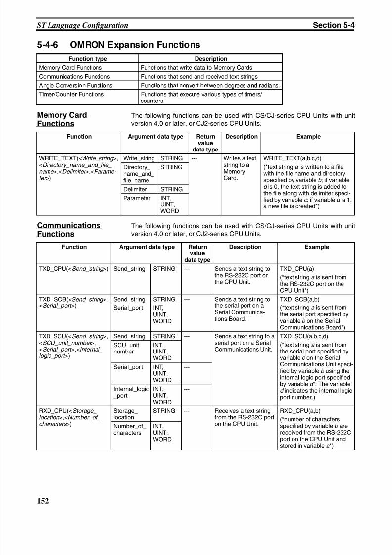
8/11/2019 CX-Programmer V9 Operation Manual FB ST.pdf
http://slidepdf.com/reader/full/cx-programmer-v9-operation-manual-fb-stpdf 178/254
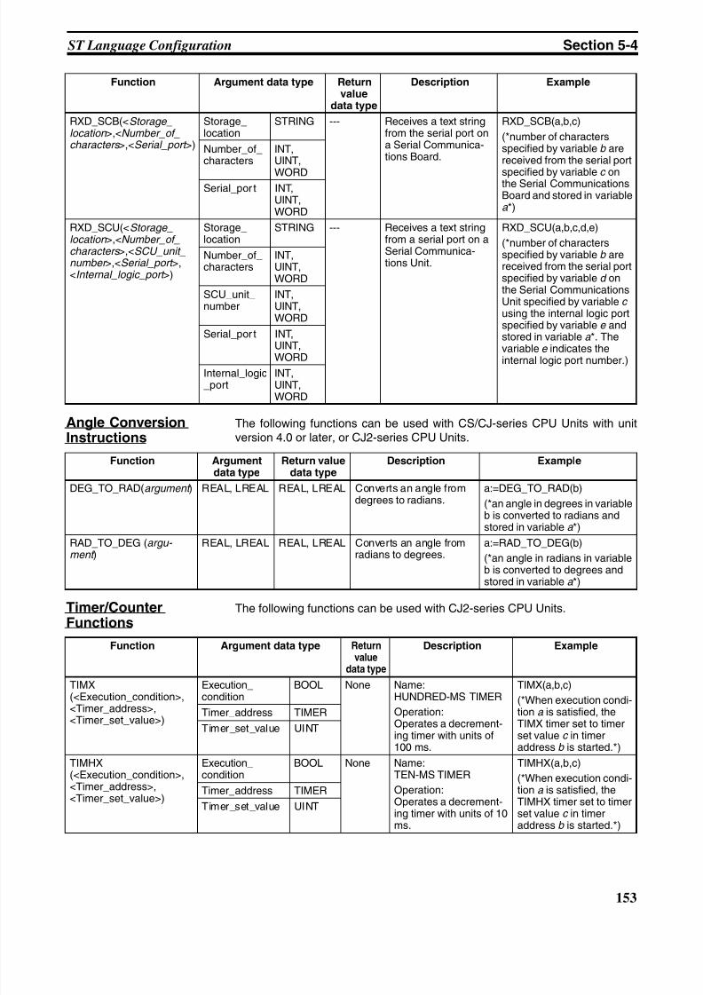
8/11/2019 CX-Programmer V9 Operation Manual FB ST.pdf
http://slidepdf.com/reader/full/cx-programmer-v9-operation-manual-fb-stpdf 179/254
153
ST Language Configuration Section 5-4
Angle ConversionInstructions
The following functions can be used with CS/CJ-series CPU Units with unitversion 4.0 or later, or CJ2-series CPU Units.
Timer/CounterFunctions
The following functions can be used with CJ2-series CPU Units.
RXD_SCB(<Storage_location >,<Number_of_characters >,<Serial_port >)
Storage_location
STRING --- Receives a text stringfrom the serial port ona Serial Communica-tions Board.
RXD_SCB(a,b,c)
(*number of charactersspecified by variable b arereceived from the serial port
specified by variable c onthe Serial CommunicationsBoard and stored in variablea *)
Number_of_characters
INT,UINT,
WORDSerial_por t INT,
UINT,WORD
RXD_SCU(<Storage_location >,<Number_of_characters >,<SCU_unit_number >,<Serial_port >,<Internal_logic_port >)
Storage_location
STRING --- Receives a text stringfrom a serial port on aSerial Communica-tions Unit.
RXD_SCU(a,b,c,d,e)
(*number of charactersspecified by variable b arereceived from the serial portspecified by variable d onthe Serial CommunicationsUnit specified by variable c using the internal logic portspecified by variable e andstored in variable a *. The
variable e indicates theinternal logic port number.)
Number_of_characters
INT,UINT,WORD
SCU_unit_number
INT,UINT,WORD
Serial_por t INT,
UINT,WORD
Internal_logic_port
INT,UINT,WORD
Function Argument data type Returnvalue
data type
Description Example
Function Argumentdata type
Return valuedata type
Description Example
DEG_TO_RAD(argument ) REAL, LREAL REAL, LREAL Converts an angle fromdegrees to radians.
a:=DEG_TO_RAD(b)
(*an angle in degrees in variableb is converted to radians andstored in variable a *)
RAD_TO_DEG (argu- ment )
REAL, LREAL REAL, LREAL Converts an angle fromradians to degrees.
a:=RAD_TO_DEG(b)
(*an angle in radians in variableb is converted to degrees andstored in variable a *)
Function Argument data type Returnvalue
data type
Description Example
TIMX
(<Execution_condition>,<Timer_address>,<Timer_set_value>)
Execution_
condition
BOOL None Name:
HUNDRED-MS TIMEROperation:Operates a decrement-ing timer with units of100 ms.
TIMX(a,b,c)
(*When execution condi-tion a is satisfied, theTIMX timer set to timerset value c in timeraddress b is started.*)
Timer_address TIMER
Timer_set_value UINT
TIMHX(<Execution_condition>,<Timer_address>,<Timer_set_value>)
Execution_condition
BOOL None Name:TEN-MS TIMER
Operation:Operates a decrement-ing timer with units of 10ms.
TIMHX(a,b,c)
(*When execution condi-tion a is satisfied, theTIMHX timer set to timerset value c in timeraddress b is started.*)
Timer_address TIMER
Timer_set_value UINT
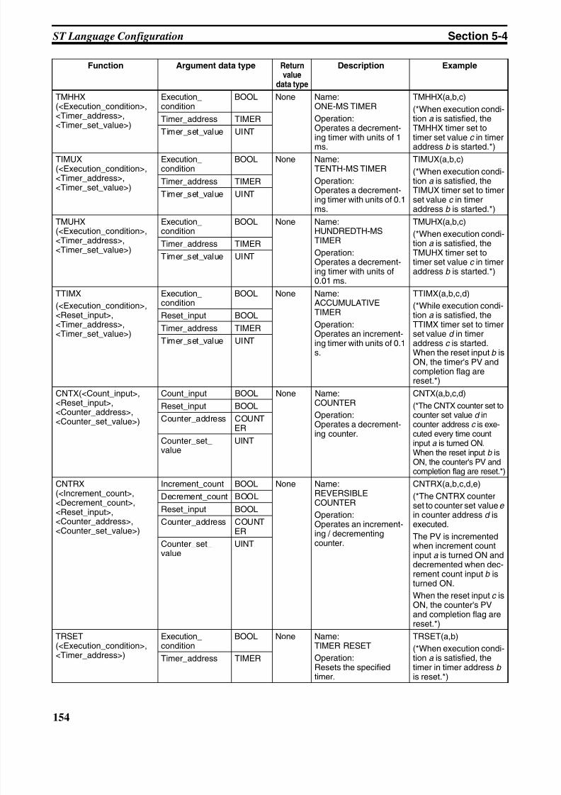
8/11/2019 CX-Programmer V9 Operation Manual FB ST.pdf
http://slidepdf.com/reader/full/cx-programmer-v9-operation-manual-fb-stpdf 180/254
154
ST Language Configuration Section 5-4
TMHHX(<Execution_condition>,<Timer_address>,<Timer_set_value>)
Execution_condition
BOOL None Name:ONE-MS TIMER
Operation:Operates a decrement-
ing timer with units of 1ms.
TMHHX(a,b,c)
(*When execution condi-tion a is satisfied, theTMHHX timer set to
timer set value c in timeraddress b is started.*)
Timer_address TIMER
Timer_set_value UINT
TIMUX(<Execution_condition>,<Timer_address>,<Timer_set_value>)
Execution_condition
BOOL None Name:TENTH-MS TIMER
Operation:Operates a decrement-ing timer with units of 0.1ms.
TIMUX(a,b,c)
(*When execution condi-tion a is satisfied, theTIMUX timer set to timerset value c in timeraddress b is started.*)
Timer_address TIMER
Timer_set_value UINT
TMUHX(<Execution_condition>,<Timer_address>,<Timer_set_value>)
Execution_condition
BOOL None Name:HUNDREDTH-MSTIMER
Operation:Operates a decrement-ing timer with units of
0.01 ms.
TMUHX(a,b,c)
(*When execution condi-tion a is satisfied, theTMUHX timer set totimer set value c in timeraddress b is started.*)
Timer_address TIMER
Timer_set_value UINT
TTIMX
(<Execution_condition>,<Reset_input>,<Timer_address>,<Timer_set_value>)
Execution_condition
BOOL None Name:ACCUMULATIVETIMER
Operation:Operates an increment-ing timer with units of 0.1s.
TTIMX(a,b,c,d)
(*While execution condi-tion a is satisfied, theTTIMX timer set to timerset value d in timeraddress c is started.When the reset input b isON, the timer's PV andcompletion flag arereset.*)
Reset_input BOOL
Timer_address TIMER
Timer_set_value UINT
CNTX(<Count_input>,<Reset_input>,<Counter_address>,<Counter_set_value>)
Count_input BOOL None Name:COUNTER
Operation:Operates a decrement-ing counter.
CNTX(a,b,c,d)
(*The CNTX counter set to
counter set value d incounter address c is exe-cuted every time countinput a is turned ON.When the reset input b isON, the counter's PV andcompletion flag are reset.*)
Reset_input BOOL
Counter_address COUNTER
Counter_set_value
UINT
CNTRX(<Increment_count>,<Decrement_count>,<Reset_input>,<Counter_address>,<Counter_set_value>)
Increment_count BOOL None Name:REVERSIBLECOUNTER
Operation:Operates an increment-ing / decrementingcounter.
CNTRX(a,b,c,d,e)
(*The CNTRX counterset to counter set value e in counter address d isexecuted.
The PV is incrementedwhen increment count
input a is turned ON anddecremented when dec-rement count input b isturned ON.
When the reset input c isON, the counter's PVand completion flag arereset.*)
Decrement_count BOOL
Reset_input BOOL
Counter_address COUNTER
Counter_set_
value
UINT
TRSET(<Execution_condition>,<Timer_address>)
Execution_condition
BOOL None Name:TIMER RESET
Operation:Resets the specifiedtimer.
TRSET(a,b)
(*When execution condi-tion a is satisfied, thetimer in timer address b is reset.*)
Timer_address TIMER
Function Argument data type Returnvalue
data type
Description Example
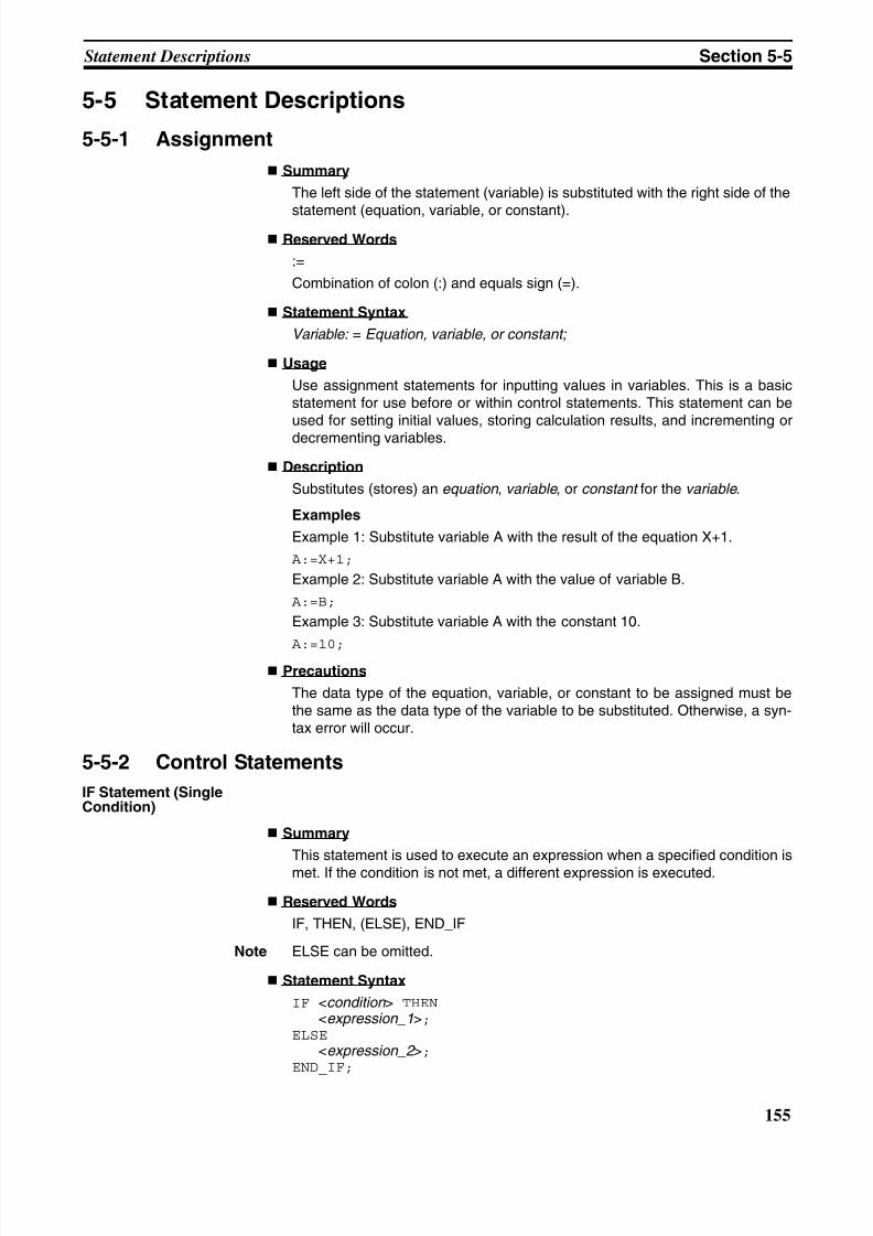
8/11/2019 CX-Programmer V9 Operation Manual FB ST.pdf
http://slidepdf.com/reader/full/cx-programmer-v9-operation-manual-fb-stpdf 181/254
155
Statement Descriptions Section 5-5
5-5 Statement Descriptions
5-5-1 Assignment
Summary
The left side of the statement (variable) is substituted with the right side of the
statement (equation, variable, or constant). Reserved Words
:=
Combination of colon (:) and equals sign (=).
Statement Syntax
Variable: = Equation, variable, or constant;
Usage
Use assignment statements for inputting values in variables. This is a basicstatement for use before or within control statements. This statement can beused for setting initial values, storing calculation results, and incrementing or
decrementing variables.
Description
Substitutes (stores) an equation , variable , or constant for the variable .
Examples
Example 1: Substitute variable A with the result of the equation X+1.
A:=X+1;
Example 2: Substitute variable A with the value of variable B.
A:=B;
Example 3: Substitute variable A with the constant 10.
A:=10; Precautions
The data type of the equation, variable, or constant to be assigned must bethe same as the data type of the variable to be substituted. Otherwise, a syn-tax error will occur.
5-5-2 Control Statements
IF Statement (SingleCondition)
Summary
This statement is used to execute an expression when a specified condition ismet. If the condition is not met, a different expression is executed.
Reserved Words
IF, THEN, (ELSE), END_IF
Note ELSE can be omitted.
Statement Syntax
IF <condition > THEN <expression_1>;ELSE <expression_2 >;END_IF;
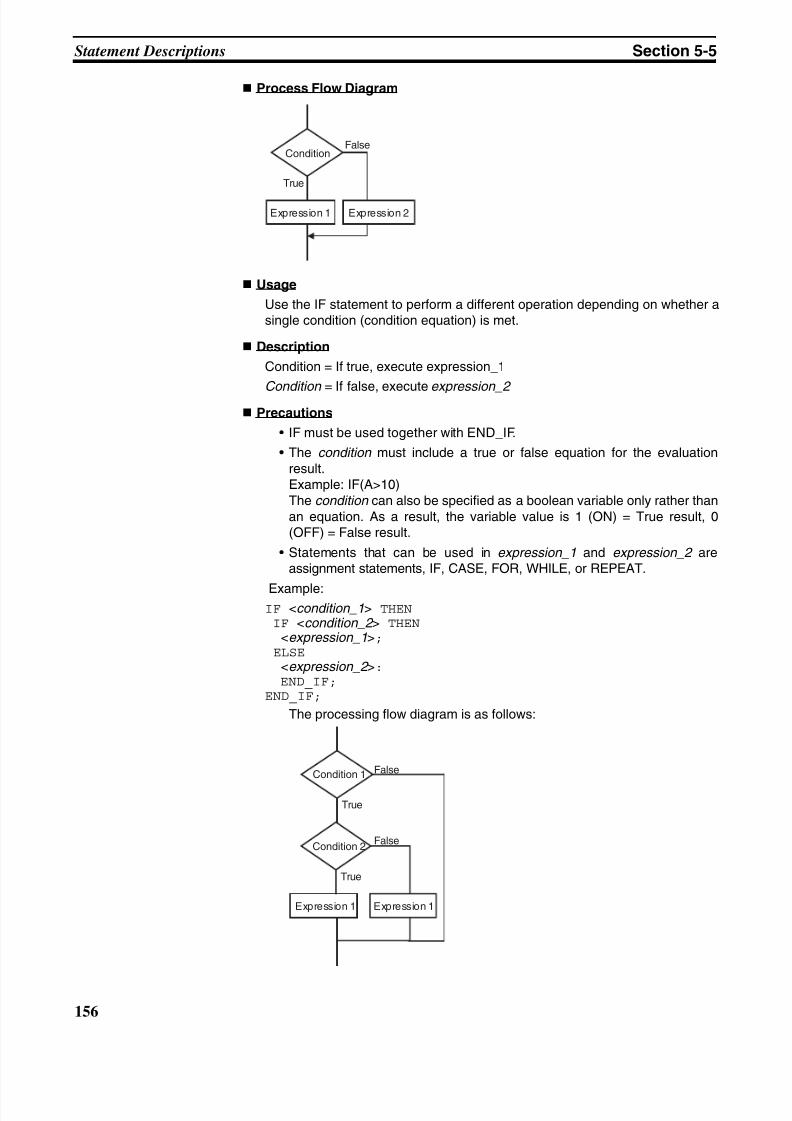
8/11/2019 CX-Programmer V9 Operation Manual FB ST.pdf
http://slidepdf.com/reader/full/cx-programmer-v9-operation-manual-fb-stpdf 182/254
156
Statement Descriptions Section 5-5
Process Flow Diagram
Usage
Use the IF statement to perform a different operation depending on whether asingle condition (condition equation) is met.
Description
Condition = If true, execute expression_1
Condition = If false, execute expression_2 Precautions
• IF must be used together with END_IF.
• The condition must include a true or false equation for the evaluationresult.Example: IF(A>10)The condition can also be specified as a boolean variable only rather thanan equation. As a result, the variable value is 1 (ON) = True result, 0(OFF) = False result.
• Statements that can be used in expression_1 and expression_2 areassignment statements, IF, CASE, FOR, WHILE, or REPEAT.
Example:IF <condition_1> THEN IF <condition_2 > THEN <expression_1>; ELSE <expression_2 >: END_IF;END_IF;
The processing flow diagram is as follows:
ConditionFalse
True
Expression 1 Expression 2
Condition 1
Condition 2
False
True
False
True
Expression 1 Expression 1
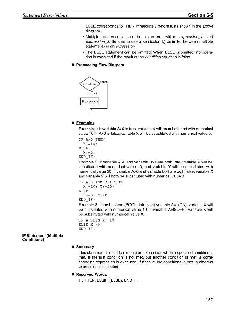
8/11/2019 CX-Programmer V9 Operation Manual FB ST.pdf
http://slidepdf.com/reader/full/cx-programmer-v9-operation-manual-fb-stpdf 183/254
157
Statement Descriptions Section 5-5
ELSE corresponds to THEN immediately before it, as shown in the abovediagram.
• Multiple statements can be executed within expression_1 andexpression_2. Be sure to use a semicolon (;) delimiter between multiplestatements in an expression .
• The ELSE statement can be omitted. When ELSE is omitted, no opera-
tion is executed if the result of the condition equation is false. Processing Flow Diagram
Examples
Example 1: If variable A>0 is true, variable X will be substituted with numericalvalue 10. If A>0 is false, variable X will be substituted with numerical value 0.
IF A>0 THEN X:=10;ELSE X:=0;END_IF;
Example 2: If variable A>0 and variable B>1 are both true, variable X will besubstituted with numerical value 10, and variable Y will be substituted withnumerical value 20. If variable A>0 and variable B>1 are both false, variable Xand variable Y will both be substituted with numerical value 0.
IF A>0 AND B>1 THEN X:=10; Y:=20;ELSE X:=0; Y:=0;END_IF;
Example 3: If the boolean (BOOL data type) variable A=1(ON), variable X willbe substituted with numerical value 10. If variable A=0(OFF), variable X willbe substituted with numerical value 0.
IF A THEN X:=10;ELSE X:=0;END_IF;
IF Statement (MultipleConditions)
Summary
This statement is used to execute an expression when a specified condition ismet. If the first condition is not met, but another condition is met, a corre-sponding expression is executed. If none of the conditions is met, a differentexpression is executed.
Reserved Words
IF, THEN, ELSIF, (ELSE), END_IF
ConditionFalse
True
Expression
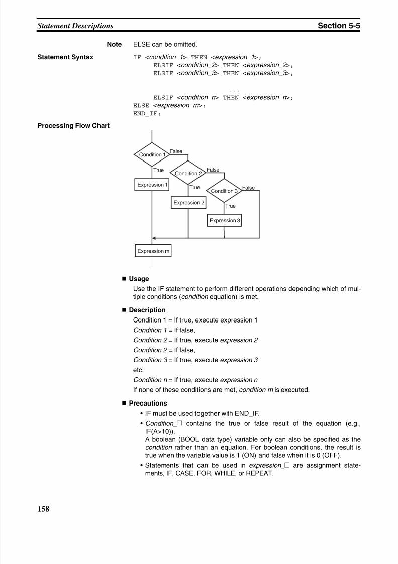
8/11/2019 CX-Programmer V9 Operation Manual FB ST.pdf
http://slidepdf.com/reader/full/cx-programmer-v9-operation-manual-fb-stpdf 184/254
158
Statement Descriptions Section 5-5
Note ELSE can be omitted.
Statement Syntax IF <condition_1> THEN <expression_1>; ELSIF <condition_2 > THEN <expression_2 >; ELSIF <condition_3 > THEN <expression_3 >;
...
ELSIF <condition_n > THEN <expression_n >;ELSE <expression_m >;END_IF;
Processing Flow Chart
Usage
Use the IF statement to perform different operations depending which of mul-
tiple conditions (condition equation) is met.
Description
Condition 1 = If true, execute expression 1
Condition 1 = If false,
Condition 2 = If true, execute expression 2
Condition 2 = If false,
Condition 3 = If true, execute expression 3
etc.
Condition n = If true, execute expression n
If none of these conditions are met, condition m is executed.
Precautions
• IF must be used together with END_IF.
• Condition_@ contains the true or false result of the equation (e.g.,IF(A>10)).A boolean (BOOL data type) variable only can also be specified as thecondition rather than an equation. For boolean conditions, the result istrue when the variable value is 1 (ON) and false when it is 0 (OFF).
• Statements that can be used in expression_@ are assignment state-ments, IF, CASE, FOR, WHILE, or REPEAT.
Condition 1
Condition 2
Condition 3
False
False
False
True
True
True
Expression 1
Expression 2
Expression 3
Expression m
8/11/2019 CX-Programmer V9 Operation Manual FB ST.pdf
http://slidepdf.com/reader/full/cx-programmer-v9-operation-manual-fb-stpdf 185/254
159
Statement Descriptions Section 5-5
• Multiple statements can be executed in expression_@. Be sure to use asemicolon (;) delimiter between multiple statements in an expression .
• The ELSE statement can be omitted. When ELSE is omitted, no opera-tion is executed if the result of any condition equation is false.
Examples
Example 1: If variable A>0 is true, variable X will be substituted with numericalvalue 10.If A>0 is false, but variable B=1, variable X will be substituted with numericalvalue 1.If A>0 is false, but variable B=2, variable X will be substituted with numericalvalue 2.If either of these conditions is met, variable X will be substituted with numeri-cal value 0.
IF A>0 THEN X:=10; ELSIF B=1 THEN X:=1; ELSIF B=2 THEN X:=2;ELSE X:=0;END_IF;
CASE Statement
Summary
This statement executes an expression containing a selected integer thatmatches the value from an integer equation. If the selected integer value isnot the same, either no expression or a specified expression is executed.
Reserved Word
CASE
Statement Syntax
CASE <integer_equation > OF
<integer_equation _value_1 >:<expression_1>; <integer_equation _value_2 >:<expression_2 >;...
<integer_equation _value_n >:<expression_n >;ELSE <expression_m >;END_CASE;
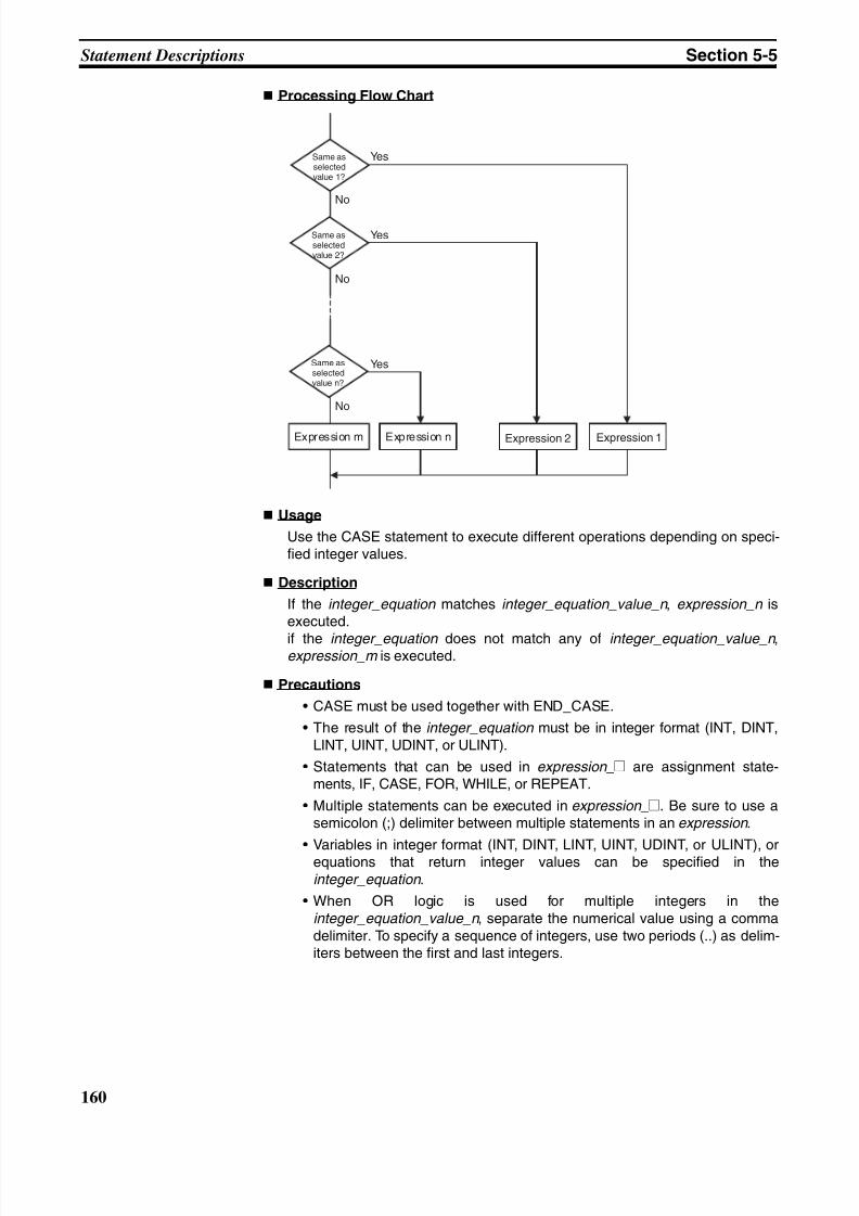
8/11/2019 CX-Programmer V9 Operation Manual FB ST.pdf
http://slidepdf.com/reader/full/cx-programmer-v9-operation-manual-fb-stpdf 186/254
160
Statement Descriptions Section 5-5
Processing Flow Chart
Usage
Use the CASE statement to execute different operations depending on speci-fied integer values.
Description
If the integer_equation matches integer_equation_value_n , expression_n isexecuted.
if the integer_equation does not match any of integer_equation_value_n ,expression_m is executed.
Precautions
• CASE must be used together with END_CASE.
• The result of the integer_equation must be in integer format (INT, DINT,LINT, UINT, UDINT, or ULINT).
• Statements that can be used in expression_@ are assignment state-ments, IF, CASE, FOR, WHILE, or REPEAT.
• Multiple statements can be executed in expression_@. Be sure to use asemicolon (;) delimiter between multiple statements in an expression .
• Variables in integer format (INT, DINT, LINT, UINT, UDINT, or ULINT), orequations that return integer values can be specified in theinteger_equation .
• When OR logic is used for multiple integers in theinteger_equation_value_n , separate the numerical value using a commadelimiter. To specify a sequence of integers, use two periods (..) as delim-iters between the first and last integers.
Yes
Yes
Yes
No
No
No
Expression m Expression n Expression 2 Expression 1
Same asselectedvalue 1?
Same asselectedvalue 2?
Same asselectedvalue n?
8/11/2019 CX-Programmer V9 Operation Manual FB ST.pdf
http://slidepdf.com/reader/full/cx-programmer-v9-operation-manual-fb-stpdf 187/254
161
Statement Descriptions Section 5-5
Examples
Example 1: If variable A is 1, variable X is substituted with numerical value 1.If variable A is 2, variable X is substituted with numerical value 2. If variable Ais 3, variable X is substituted with numerical value 3. If neither of these casesmatches, variable Y will be substituted with 0.
CASE A OF
1:X:=1; 2:X:=2; 3:X:=3;ELSE Y:=0;END_CASE;
Example 2: If variable A is 1, variable X is substituted with numerical value 1.If variable A is 2 or 5, variable X is substituted with numerical value 2. If vari-able A is a value between 6 and 10, variable X is substituted with numericalvalue 3. If variable A is 11, 12, or a value between 15 and 20, variable X issubstituted with numerical value 4. If neither of these cases matches, variableY will be substituted with 0.
CASE A OF1:X:=1;
2,5:X:=2;6..10:X:=3;11,12,15..20:X:=4;ELSE Y:=0;END_CASE;
FOR Statement
Summary
This statement is used to execute a specified expression repeatedly until avariable (referred to here as an iteration variable) reaches a specified value.
Reserved Words
FOR, TO, (BY), DO, END_FORNote BY can be omitted.
Statement Syntax
FOR <iteration_variable >:= <initial_value > TO <final_value_equation > BY<increment_value_equation >DO <expression >;END_FOR;
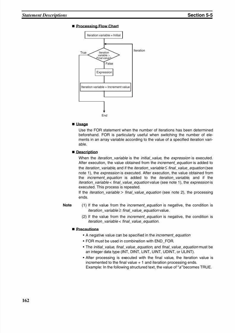
8/11/2019 CX-Programmer V9 Operation Manual FB ST.pdf
http://slidepdf.com/reader/full/cx-programmer-v9-operation-manual-fb-stpdf 188/254
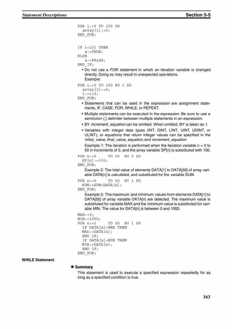
8/11/2019 CX-Programmer V9 Operation Manual FB ST.pdf
http://slidepdf.com/reader/full/cx-programmer-v9-operation-manual-fb-stpdf 189/254
163
Statement Descriptions Section 5-5
FOR i:=0 TO 100 DO array[i]:=0;END_FOR;
IF i=101 THEN a:=TRUE;
ELSE a:=FALSE;END_IF;
• Do not use a FOR statement in which an iteration variable is changeddirectly. Doing so may result in unexpected operations.Example:
FOR i:=0 TO 100 BY 1 DO array[i]:=0; i:=i+5;END_FOR;
• Statements that can be used in the expression are assignment state-ments, IF, CASE, FOR, WHILE, or REPEAT.
• Multiple statements can be executed in the expression. Be sure to use asemicolon (;) delimiter between multiple statements in an expression .
• BY increment_equation can be omitted. When omitted, BY is taken as 1.
• Variables with integer data types (INT, DINT, LINT, UINT, UDINT, orULINT), or equations that return integer values can be specified in theinitial_value, final_value_equation, and increment_equation.
Example 1: The iteration is performed when the iteration variable n = 0 to50 in increments of 5, and the array variable SP[n] is substituted with 100.
FOR n:=0 TO 50 BY 5 DO SP[n]:=100;END_FOR;
Example 2: The total value of elements DATA[1] to DATA[50] of array vari-able DATA[n] is calculated, and substituted for the variable SUM.
FOR n:=0 TO 50 BY 1 DO SUM:=SUM+DATA[n];END_FOR;
Example 3: The maximum and minimum values from elements DATA[1] toDATA[50] of array variable DATA[n] are detected. The maximum value issubstituted for variable MAX and the minimum value is substituted for vari-able MIN. The value for DATA[n] is between 0 and 1000.
MAX:=0;MIN:=1000;FOR n:=1 TO 50 BY 1 DO IF DATA[n]>MAX THEN
MAX:=DATA[n]; END IF; IF DATA[n]<MIN THEN MIN:=DATA[n]; END IF;END_FOR;
WHILE Statement
Summary
This statement is used to execute a specified expression repeatedly for aslong as a specified condition is true.
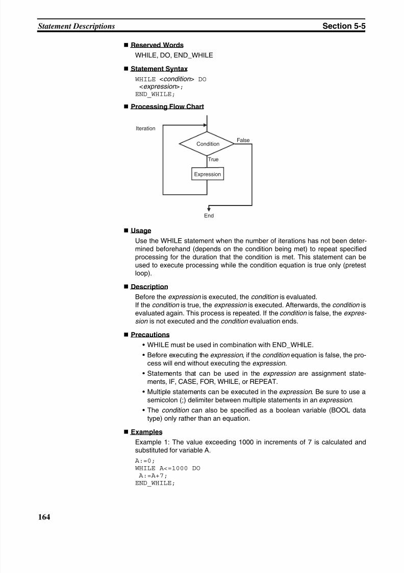
8/11/2019 CX-Programmer V9 Operation Manual FB ST.pdf
http://slidepdf.com/reader/full/cx-programmer-v9-operation-manual-fb-stpdf 190/254
164
Statement Descriptions Section 5-5
Reserved Words
WHILE, DO, END_WHILE
Statement Syntax
WHILE <condition > DO <expression >;END_WHILE;
Processing Flow Chart
Usage
Use the WHILE statement when the number of iterations has not been deter-mined beforehand (depends on the condition being met) to repeat specifiedprocessing for the duration that the condition is met. This statement can beused to execute processing while the condition equation is true only (pretestloop).
Description
Before the expression is executed, the condition is evaluated.If the condition is true, the expression is executed. Afterwards, the condition isevaluated again. This process is repeated. If the condition is false, the expres- sion is not executed and the condition evaluation ends.
Precautions
• WHILE must be used in combination with END_WHILE.
• Before executing the expression , if the condition equation is false, the pro-cess will end without executing the expression.
• Statements that can be used in the expression are assignment state-ments, IF, CASE, FOR, WHILE, or REPEAT.
• Multiple statements can be executed in the expression . Be sure to use a
semicolon (;) delimiter between multiple statements in an expression .• The condition can also be specified as a boolean variable (BOOL data
type) only rather than an equation.
Examples
Example 1: The value exceeding 1000 in increments of 7 is calculated andsubstituted for variable A.
A:=0;WHILE A<=1000 DO A:=A+7;END_WHILE;
Iteration
Condition
Expression
False
True
End
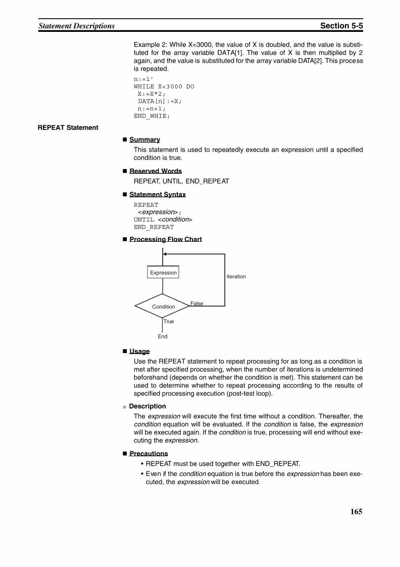
8/11/2019 CX-Programmer V9 Operation Manual FB ST.pdf
http://slidepdf.com/reader/full/cx-programmer-v9-operation-manual-fb-stpdf 191/254
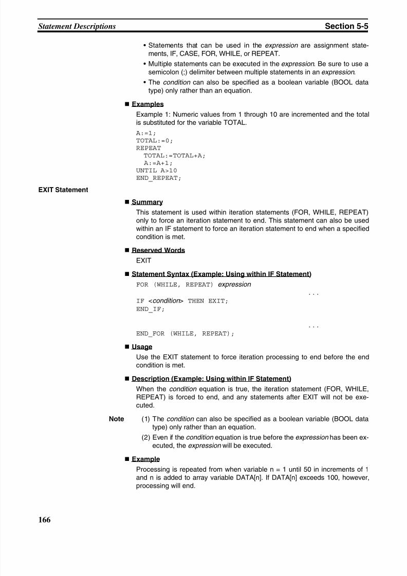
8/11/2019 CX-Programmer V9 Operation Manual FB ST.pdf
http://slidepdf.com/reader/full/cx-programmer-v9-operation-manual-fb-stpdf 192/254
166
Statement Descriptions Section 5-5
• Statements that can be used in the expression are assignment state-ments, IF, CASE, FOR, WHILE, or REPEAT.
• Multiple statements can be executed in the expression . Be sure to use asemicolon (;) delimiter between multiple statements in an expression .
• The condition can also be specified as a boolean variable (BOOL datatype) only rather than an equation.
Examples
Example 1: Numeric values from 1 through 10 are incremented and the totalis substituted for the variable TOTAL.
A:=1;TOTAL:=0;REPEAT TOTAL:=TOTAL+A; A:=A+1;UNTIL A>10END_REPEAT;
EXIT Statement
SummaryThis statement is used within iteration statements (FOR, WHILE, REPEAT)only to force an iteration statement to end. This statement can also be usedwithin an IF statement to force an iteration statement to end when a specifiedcondition is met.
Reserved Words
EXIT
Statement Syntax (Example: Using within IF Statement)
FOR (WHILE, REPEAT) expression ...
IF <condition > THEN EXIT;END_IF;
...
END_FOR (WHILE, REPEAT);
Usage
Use the EXIT statement to force iteration processing to end before the endcondition is met.
Description (Example: Using within IF Statement)
When the condition equation is true, the iteration statement (FOR, WHILE,REPEAT) is forced to end, and any statements after EXIT will not be exe-
cuted.
Note (1) The condition can also be specified as a boolean variable (BOOL datatype) only rather than an equation.
(2) Even if the condition equation is true before the expression has been ex-ecuted, the expression will be executed.
Example
Processing is repeated from when variable n = 1 until 50 in increments of 1and n is added to array variable DATA[n]. If DATA[n] exceeds 100, however,processing will end.
8/11/2019 CX-Programmer V9 Operation Manual FB ST.pdf
http://slidepdf.com/reader/full/cx-programmer-v9-operation-manual-fb-stpdf 193/254
167
Statement Descriptions Section 5-5
FOR n:=1; TO 50 BY 1 DO
DATA[n]:=DATA[n]+n;
IF DATA[n]>100 THEN EXIT;
END_IF;
END_FOR;
RETURN Statement
Summary
The function of the RETURN statement depends on the type of program inwhich ST is used.
• ST program:Forcibly ends the ST task that is being executed, and executes the nexttask.
• ST used in SFC:Forcibly ends the action program that is being executed, and executes thenext action program or transition program.
• ST used in a function block:Forcibly ends the ST-language function block containing the RETURN
statement, returns to the place in the calling function block instance wherethe call occurred, and executes the next instruction.
Reserved Words
RETURN
Statement Syntax
RETURN
Usage
Use the RETURN statement to forcibly end an SFC program and functionblock that is executing an ST task.
Function Block CallStatement
Summary
This statement calls a function block definition.
Reserved Words
None
Statement Syntax
Enter the arguments (specified variable values that are passed to the calledfunction block’s input variables) and return value (specified variable thatreceives the function block’s output variable value) in parentheses after the
instance name (see note). The two methods (entry method 1 and entrymethod 2) that can be used to enter these parameters are described in the fol-lowing paragraphs.
Note The data type is any of the function block’s internal variable names (when STis used in the function block’s instance) or global variable names (when ST isused in an ST task or SFC action program).
Entry Method 1
Use this method to enter both the argument specification (called functionblock definition’s variable name) and return value specification.
A(B:=C, .......... ,D=>E)
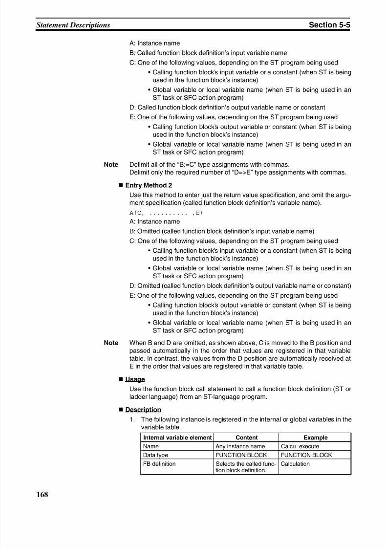
8/11/2019 CX-Programmer V9 Operation Manual FB ST.pdf
http://slidepdf.com/reader/full/cx-programmer-v9-operation-manual-fb-stpdf 194/254
168
Statement Descriptions Section 5-5
A: Instance name
B: Called function block definition’s input variable name
C: One of the following values, depending on the ST program being used
• Calling function block’s input variable or a constant (when ST is beingused in the function block’s instance)
• Global variable or local variable name (when ST is being used in an
ST task or SFC action program)
D: Called function block definition’s output variable name or constant
E: One of the following values, depending on the ST program being used
• Calling function block’s output variable or constant (when ST is beingused in the function block’s instance)
• Global variable or local variable name (when ST is being used in anST task or SFC action program)
Note Delimit all of the “B:=C” type assignments with commas.Delimit only the required number of “D=>E” type assignments with commas.
Entry Method 2
Use this method to enter just the return value specification, and omit the argu-ment specification (called function block definition’s variable name).
A(C, .......... ,E)
A: Instance name
B: Omitted (called function block definition’s input variable name)
C: One of the following values, depending on the ST program being used
• Calling function block’s input variable or a constant (when ST is beingused in the function block’s instance)
• Global variable or local variable name (when ST is being used in anST task or SFC action program)
D: Omitted (called function block definition’s output variable name or constant)E: One of the following values, depending on the ST program being used
• Calling function block’s output variable or constant (when ST is beingused in the function block’s instance)
• Global variable or local variable name (when ST is being used in anST task or SFC action program)
Note When B and D are omitted, as shown above, C is moved to the B position andpassed automatically in the order that values are registered in that variabletable. In contrast, the values from the D position are automatically received atE in the order that values are registered in that variable table.
Usage
Use the function block call statement to call a function block definition (ST orladder language) from an ST-language program.
Description
1. The following instance is registered in the internal or global variables in thevariable table.
Internal variable element Content Example
Name Any instance name Calcu_execute
Data type FUNCTION BLOCK FUNCTION BLOCK
FB definition Selects the called func-tion block definition.
Calculation
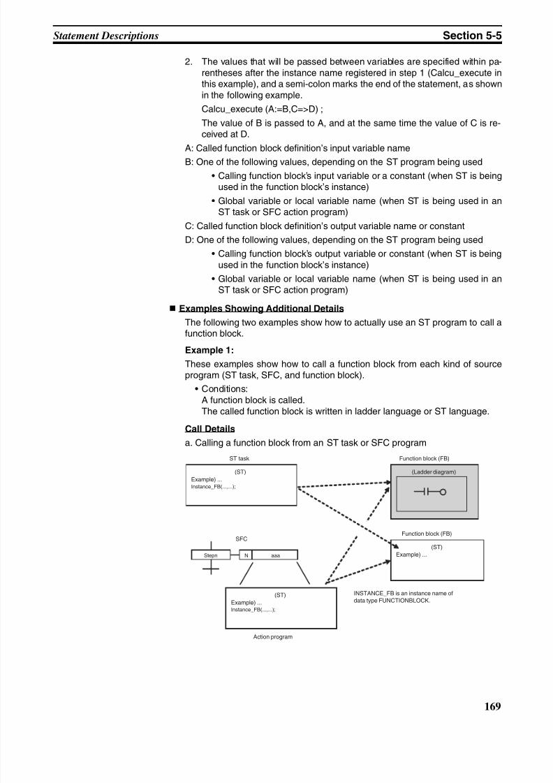
8/11/2019 CX-Programmer V9 Operation Manual FB ST.pdf
http://slidepdf.com/reader/full/cx-programmer-v9-operation-manual-fb-stpdf 195/254
169
Statement Descriptions Section 5-5
2. The values that will be passed between variables are specified within pa-rentheses after the instance name registered in step 1 (Calcu_execute inthis example), and a semi-colon marks the end of the statement, as shownin the following example.
Calcu_execute (A:=B,C=>D) ;
The value of B is passed to A, and at the same time the value of C is re-
ceived at D.A: Called function block definition’s input variable name
B: One of the following values, depending on the ST program being used
• Calling function block’s input variable or a constant (when ST is beingused in the function block’s instance)
• Global variable or local variable name (when ST is being used in anST task or SFC action program)
C: Called function block definition’s output variable name or constant
D: One of the following values, depending on the ST program being used
• Calling function block’s output variable or constant (when ST is beingused in the function block’s instance)
• Global variable or local variable name (when ST is being used in anST task or SFC action program)
Examples Showing Additional Details
The following two examples show how to actually use an ST program to call afunction block.
Example 1:
These examples show how to call a function block from each kind of sourceprogram (ST task, SFC, and function block).
• Conditions:A function block is called.
The called function block is written in ladder language or ST language.
Call Details
a. Calling a function block from an ST task or SFC program
(ST)
Example) ...Instance_FB(...,...);
INSTANCE_FB is an instance name ofdata type FUNCTIONBLOCK.
(ST)Example) ...
(Ladder diagram)
Function block (FB)ST task
Function block (FB)
(ST)
Example) ...Instance_FB(...,...);
SFC
NStepn aaa
Action program
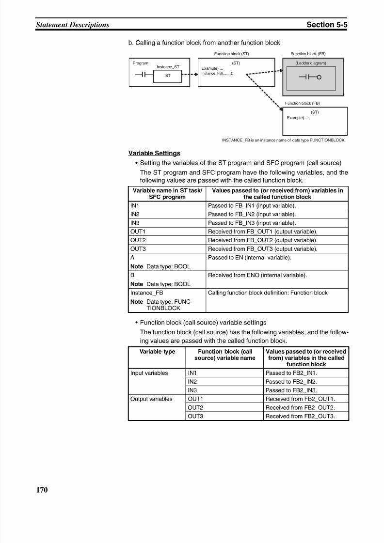
8/11/2019 CX-Programmer V9 Operation Manual FB ST.pdf
http://slidepdf.com/reader/full/cx-programmer-v9-operation-manual-fb-stpdf 196/254
170
Statement Descriptions Section 5-5
b. Calling a function block from another function block
Variable Settings
• Setting the variables of the ST program and SFC program (call source)
The ST program and SFC program have the following variables, and thefollowing values are passed with the called function block.
• Function block (call source) variable settings
The function block (call source) has the following variables, and the follow-
ing values are passed with the called function block.
Variable name in ST task/ SFC program
Values passed to (or received from) variables inthe called function block
IN1 Passed to FB_IN1 (input variable).
IN2 Passed to FB_IN2 (input variable).
IN3 Passed to FB_IN3 (input variable).
OUT1 Received from FB_OUT1 (output variable).
OUT2 Received from FB_OUT2 (output variable).
OUT3 Received from FB_OUT3 (output variable).
A
Note Data type: BOOL
Passed to EN (internal variable).
B
Note Data type: BOOL
Received from ENO (internal variable).
Instance_FB
Note Data type: FUNC-TIONBLOCK
Calling function block definition: Function block
Variable type Function block (callsource) variable name
Values passed to (or receivedfrom) variables in the called
function block
Input variables IN1 Passed to FB2_IN1.
IN2 Passed to FB2_IN2.IN3 Passed to FB2_IN3.
Output variables OUT1 Received from FB2_OUT1.
OUT2 Received from FB2_OUT2.
OUT3 Received from FB2_OUT3.
Program
ST
Instance_ST(ST)
Example) ...Instance_FB(...,...);
INSTANCE_FB is an instance name of data type FUNCTIONBLOCK.
(ST)
Example) ...
(Ladder diagram)
Function block (ST)
Function block (FB)
Function block (FB)
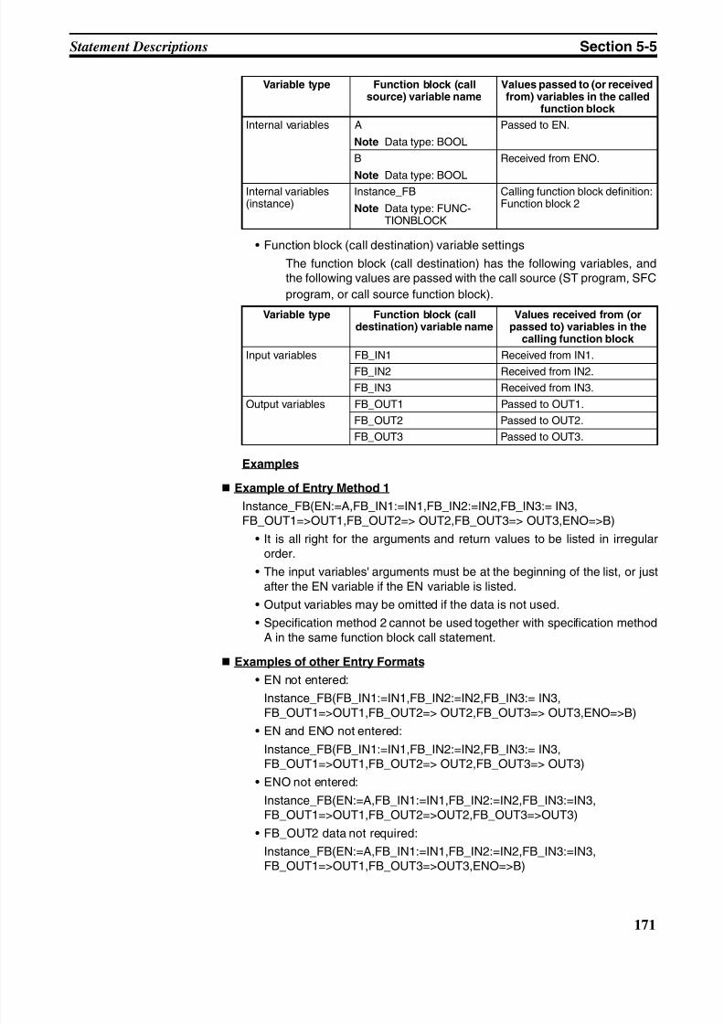
8/11/2019 CX-Programmer V9 Operation Manual FB ST.pdf
http://slidepdf.com/reader/full/cx-programmer-v9-operation-manual-fb-stpdf 197/254
171
Statement Descriptions Section 5-5
• Function block (call destination) variable settings
The function block (call destination) has the following variables, andthe following values are passed with the call source (ST program, SFC
program, or call source function block).
Examples
Example of Entry Method 1
Instance_FB(EN:=A,FB_IN1:=IN1,FB_IN2:=IN2,FB_IN3:= IN3,FB_OUT1=>OUT1,FB_OUT2=> OUT2,FB_OUT3=> OUT3,ENO=>B)
• It is all right for the arguments and return values to be listed in irregularorder.
• The input variables' arguments must be at the beginning of the list, or justafter the EN variable if the EN variable is listed.
• Output variables may be omitted if the data is not used.
• Specification method 2 cannot be used together with specification methodA in the same function block call statement.
Examples of other Entry Formats
• EN not entered:
Instance_FB(FB_IN1:=IN1,FB_IN2:=IN2,FB_IN3:= IN3,
FB_OUT1=>OUT1,FB_OUT2=> OUT2,FB_OUT3=> OUT3,ENO=>B)• EN and ENO not entered:
Instance_FB(FB_IN1:=IN1,FB_IN2:=IN2,FB_IN3:= IN3,FB_OUT1=>OUT1,FB_OUT2=> OUT2,FB_OUT3=> OUT3)
• ENO not entered:
Instance_FB(EN:=A,FB_IN1:=IN1,FB_IN2:=IN2,FB_IN3:=IN3,FB_OUT1=>OUT1,FB_OUT2=>OUT2,FB_OUT3=>OUT3)
• FB_OUT2 data not required:
Instance_FB(EN:=A,FB_IN1:=IN1,FB_IN2:=IN2,FB_IN3:=IN3,FB_OUT1=>OUT1,FB_OUT3=>OUT3,ENO=>B)
Internal variables A
Note Data type: BOOL
Passed to EN.
B
Note Data type: BOOL
Received from ENO.
Internal variables(instance)
Instance_FB
Note Data type: FUNC-TIONBLOCK
Calling function block definition:Function block 2
Variable type Function block (calldestination) variable name
Values received from (orpassed to) variables in the
calling function block
Input variables FB_IN1 Received from IN1.FB_IN2 Received from IN2.
FB_IN3 Received from IN3.
Output variables FB_OUT1 Passed to OUT1.
FB_OUT2 Passed to OUT2.
FB_OUT3 Passed to OUT3.
Variable type Function block (callsource) variable name
Values passed to (or receivedfrom) variables in the called
function block
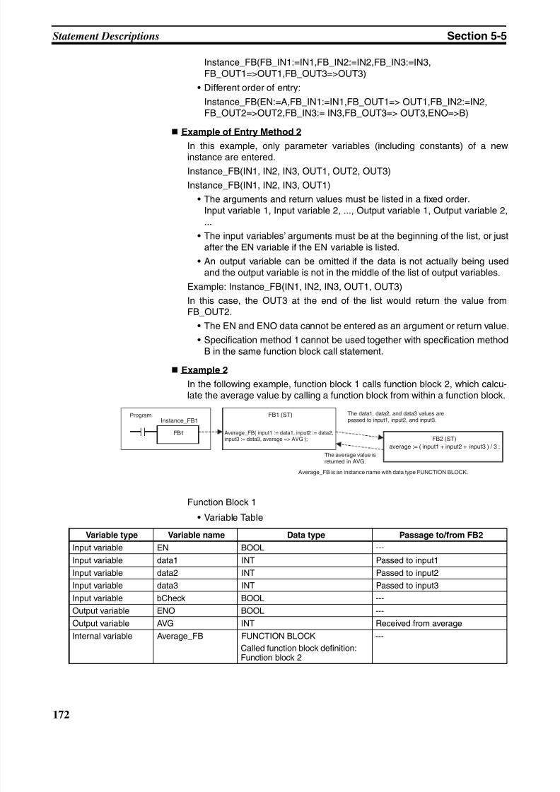
8/11/2019 CX-Programmer V9 Operation Manual FB ST.pdf
http://slidepdf.com/reader/full/cx-programmer-v9-operation-manual-fb-stpdf 198/254
172
Statement Descriptions Section 5-5
Instance_FB(FB_IN1:=IN1,FB_IN2:=IN2,FB_IN3:=IN3,FB_OUT1=>OUT1,FB_OUT3=>OUT3)
• Different order of entry:
Instance_FB(EN:=A,FB_IN1:=IN1,FB_OUT1=> OUT1,FB_IN2:=IN2,FB_OUT2=>OUT2,FB_IN3:= IN3,FB_OUT3=> OUT3,ENO=>B)
Example of Entry Method 2
In this example, only parameter variables (including constants) of a newinstance are entered.
Instance_FB(IN1, IN2, IN3, OUT1, OUT2, OUT3)
Instance_FB(IN1, IN2, IN3, OUT1)
• The arguments and return values must be listed in a fixed order.Input variable 1, Input variable 2, ..., Output variable 1, Output variable 2,...
• The input variables’ arguments must be at the beginning of the list, or justafter the EN variable if the EN variable is listed.
• An output variable can be omitted if the data is not actually being used
and the output variable is not in the middle of the list of output variables.Example: Instance_FB(IN1, IN2, IN3, OUT1, OUT3)
In this case, the OUT3 at the end of the list would return the value fromFB_OUT2.
• The EN and ENO data cannot be entered as an argument or return value.
• Specification method 1 cannot be used together with specification methodB in the same function block call statement.
Example 2
In the following example, function block 1 calls function block 2, which calcu-late the average value by calling a function block from within a function block.
Function Block 1
• Variable Table
FB1
Instance_FB1 FB1 (ST)
FB2 (ST)
average := ( input1 + input2 + input3 ) / 3 ;
Program
Average_FB( input1 := data1, input2 := data2,input3 := data3, average => AVG );
The data1, data2, and data3 values arepassed to input1, input2, and input3.
The average value isreturned in AVG.
Average_FB is an instance name with data type FUNCTION BLOCK.
Variable type Variable name Data type Passage to/from FB2
Input variable EN BOOL ---
Input variable data1 INT Passed to input1
Input variable data2 INT Passed to input2
Input variable data3 INT Passed to input3
Input variable bCheck BOOL ---
Output variable ENO BOOL ---
Output variable AVG INT Received from average
Internal variable Average_FB FUNCTION BLOCK
Called function block definition:Function block 2
---
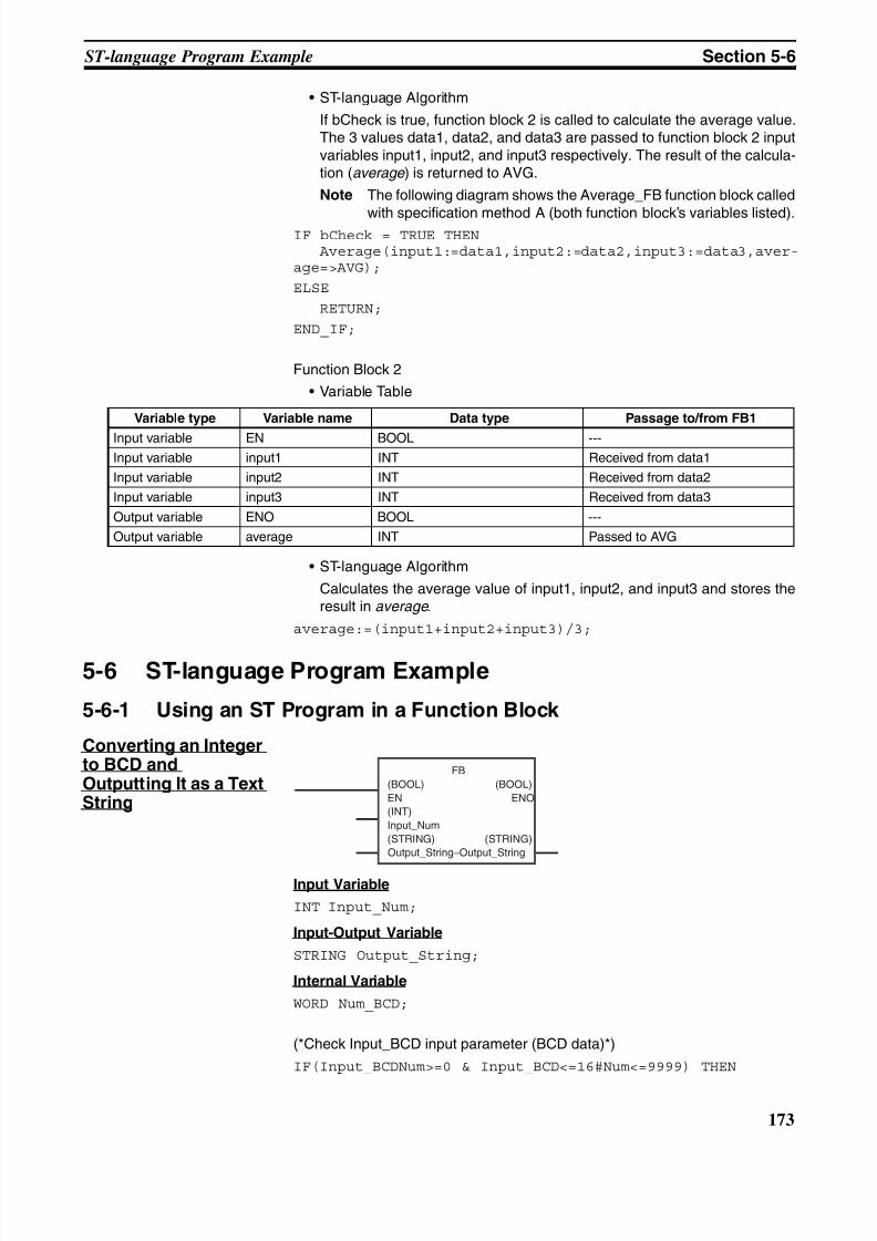
8/11/2019 CX-Programmer V9 Operation Manual FB ST.pdf
http://slidepdf.com/reader/full/cx-programmer-v9-operation-manual-fb-stpdf 199/254
173
ST-language Program Example Section 5-6
• ST-language Algorithm
If bCheck is true, function block 2 is called to calculate the average value.The 3 values data1, data2, and data3 are passed to function block 2 inputvariables input1, input2, and input3 respectively. The result of the calcula-tion (average ) is returned to AVG.
Note The following diagram shows the Average_FB function block called
with specification method A (both function block’s variables listed).IF bCheck = TRUE THEN
Average(input1:=data1,input2:=data2,input3:=data3,aver-age=>AVG);
ELSE
RETURN;
END_IF;
Function Block 2
• Variable Table
• ST-language Algorithm
Calculates the average value of input1, input2, and input3 and stores theresult in average .
average:=(input1+input2+input3)/3;
5-6 ST-language Program Example
5-6-1 Using an ST Program in a Function Block
Converting an Integerto BCD andOutputting It as a TextString
Input Variable
INT Input_Num;
Input-Output Variable
STRING Output_String;
Internal Variable
WORD Num_BCD;
(*Check Input_BCD input parameter (BCD data)*)
IF(Input_BCDNum>=0 & Input_BCD<=16#Num<=9999) THEN
Variable type Variable name Data type Passage to/from FB1
Input variable EN BOOL ---
Input variable input1 INT Received from data1
Input variable input2 INT Received from data2
Input variable input3 INT Received from data3
Output variable ENO BOOL ---
Output variable average INT Passed to AVG
FB
(BOOL)
EN
(BOOL)
ENO
(INT)
Input_Num
(STRING) (STRING)
Output_String−Output_String
8/11/2019 CX-Programmer V9 Operation Manual FB ST.pdf
http://slidepdf.com/reader/full/cx-programmer-v9-operation-manual-fb-stpdf 200/254
174
Restrictions Section 5-7
ENO:=true;
ELSE
ENO:=false;
RETURN;
END_IF;
Num_BCD:=INT_TO_BCD_WORD(Input_Num);
(*For example, if Num is 100 (16#0064), it is converted to BCD 0100*)
Output_String:=WORD_TO_STRING(Num_BCD);
(*Convert BCD 0100 to text string*)
5-7 Restrictions
5-7-1 Restrictions
Nesting
• There is no restriction on the number of nests that can be used in IF,
CASE, FOR, WHILE, or REPEAT statements.
Data Type Restrictions
• Integers can only be allocated to variables with data types WORD,DWORD, INT, DINT, UINT, UDINT, or ULINT. For example, if A is an INTdata type, A:=1; it possible. If the value is not an integer data type, a syn-tax error will occur. For example, if A is an INT data type, a syntax errorwill occur for A:=2.5;.
• If a real number (floating point decimal data) can only be allocated to vari-ables with data types REAL and UREAL. For example, if A is a REAL datatype, A:=1.5; is possible. If the value is not an real data type, a syntaxerror will occur. For example, if A is a REAL data type, a syntax error will
occur for A:=2;. Use A:=2.0;.• Bits (TRUE, FALSE) can only be allocated to variables with the BOOL
data type. For example, if A is a BOOL data type, A:=FALSE; is possible.If a BOOL data type is not used, a syntax error will occur. For example, ifA is an INT data type, a syntax error will occur for A:=FALSE;.
• Data types must all be consistent within the structured text. For example,if A, B, and C are INT data types, A:=B+C; is possible. If, however, A andB are INT data types, but C is a REAL data type or LINT data type, a syn-tax error will occur for A:=B+C;.
• In the structured text, the following cannot be used:P_CY, P_EQ, P_ER, P_N, P_GE, P_GT, P_LE, P_LT, P_NE, P_OF, andP_UF
Monitor Restrictions
• There are following restrictions on monitoring timer functions:When you use a TIMER type variable in a TENTH-MS TIMER or HUN-DREDTH-MS TIMER, the present value of the TIMER type variable of thetimer function is not displayed on the ST monitor view. In this case, "-" isdisplayed for the present value.When the present value of the TIMER type variable is used in anotherplace on the ST editor or assigned to a different variable, their present val-ues are undependable.
8/11/2019 CX-Programmer V9 Operation Manual FB ST.pdf
http://slidepdf.com/reader/full/cx-programmer-v9-operation-manual-fb-stpdf 201/254
175
Restrictions Section 5-7
• There are following restrictions on using 2-byte characters in variablenames:When you use any 2-byte characters in a variable name, insert a single-byte space between the variable and the operator. Without the space, thepresent value of the variable may not be monitored correctly.
5-7-2 Commonly Asked Questions
Q: How is a hexadecimal value expressed?
A: Add “16#” before the value, e.g., 16#123F.The prefixes 8# and 2# can also be added to express octal numbers andbinary numbers, respectively. Numbers without these prefixes will be inter-preted as decimal numbers.
Q: How many times can FOR be used?
A: In the following example, the contents of the FOR statement is executed101 times. The loop processing ends when the value of “i” is equal to 101.
FOR i:=0 TO 100 BY 1 DO a:=a+1;
END_FOR;Q: What occurs when the array subscript is exceeded?
A: For the array variable INT[10] with 10 elements, an error will not bedetected for the following type of statement. Operation will be unstable whenthis statement is executed.
i:=15;INT[i]:=10;
Q: Are the variables in the structured text editor automatically registeredin the variable tables?
A: No. Register the variables in the variable table before using them.
Q: Can ladder programming instructions be called directly?
A: No.

8/11/2019 CX-Programmer V9 Operation Manual FB ST.pdf
http://slidepdf.com/reader/full/cx-programmer-v9-operation-manual-fb-stpdf 202/254
176
Restrictions Section 5-7
8/11/2019 CX-Programmer V9 Operation Manual FB ST.pdf
http://slidepdf.com/reader/full/cx-programmer-v9-operation-manual-fb-stpdf 203/254
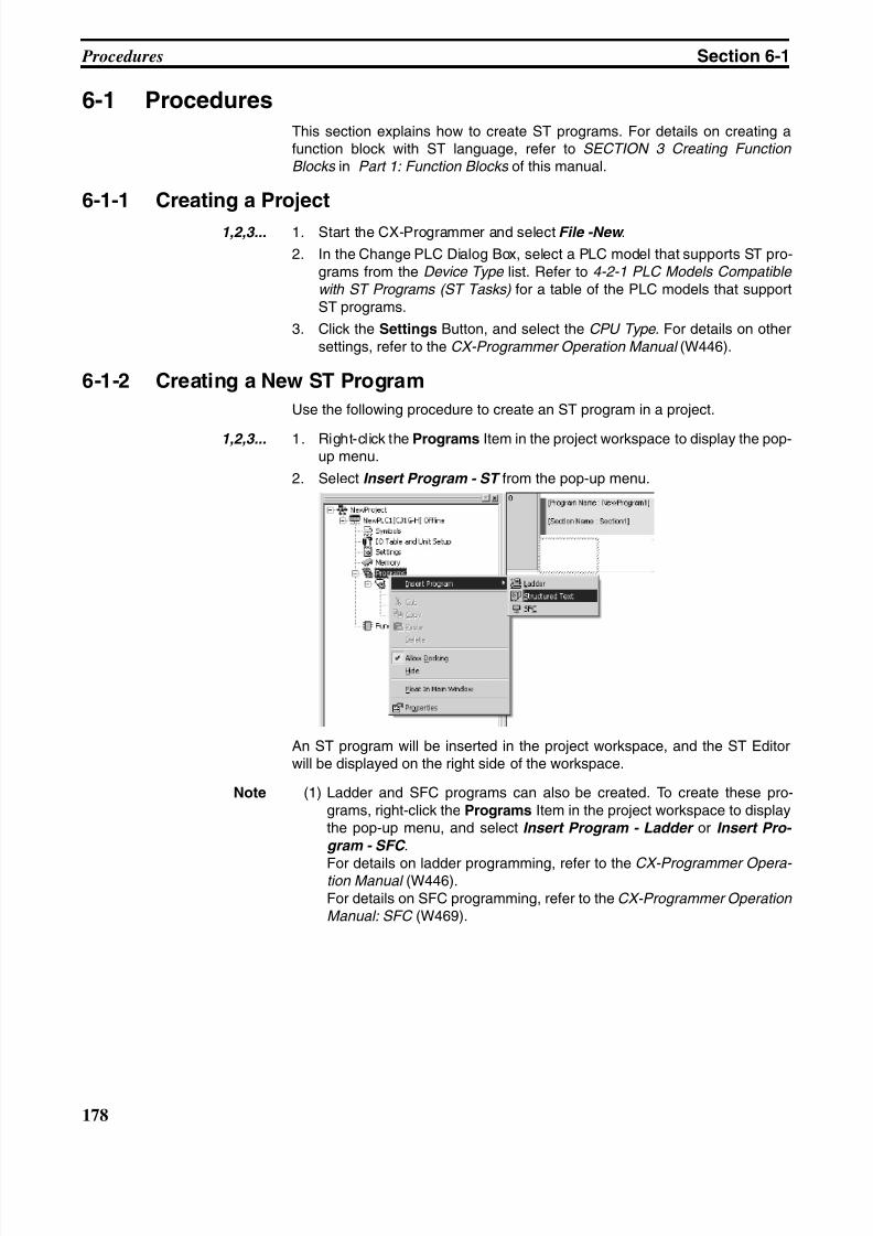
8/11/2019 CX-Programmer V9 Operation Manual FB ST.pdf
http://slidepdf.com/reader/full/cx-programmer-v9-operation-manual-fb-stpdf 204/254
178
Procedures Section 6-1
6-1 Procedures
This section explains how to create ST programs. For details on creating afunction block with ST language, refer to SECTION 3 Creating Function
Blocks in Part 1: Function Blocks of this manual.
6-1-1 Creating a Project
1,2,3... 1. Start the CX-Programmer and select File -New .
2. In the Change PLC Dialog Box, select a PLC model that supports ST pro-grams from the Device Type list. Refer to 4-2-1 PLC Models Compatible
with ST Programs (ST Tasks) for a table of the PLC models that supportST programs.
3. Click the Settings Button, and select the CPU Type. For details on othersettings, refer to the CX-Programmer Operation Manual (W446).
6-1-2 Creating a New ST Program
Use the following procedure to create an ST program in a project.
1,2,3... 1. Right-click the Programs Item in the project workspace to display the pop-up menu.
2. Select Insert Program - ST from the pop-up menu.
An ST program will be inserted in the project workspace, and the ST Editorwill be displayed on the right side of the workspace.
Note (1) Ladder and SFC programs can also be created. To create these pro-grams, right-click the Programs Item in the project workspace to displaythe pop-up menu, and select Insert Program - Ladder or Insert Pro-
gram - SFC .
For details on ladder programming, refer to the CX-Programmer Opera- tion Manual (W446).For details on SFC programming, refer to the CX-Programmer Operation Manual: SFC (W469).
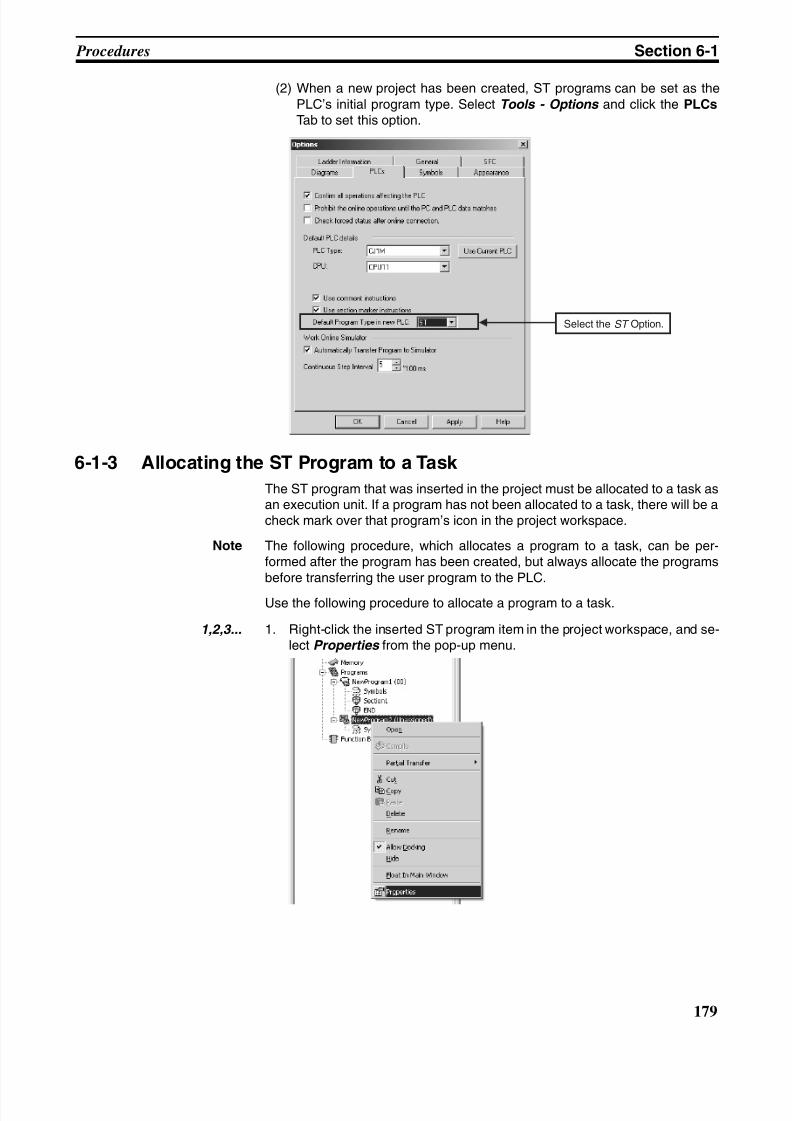
8/11/2019 CX-Programmer V9 Operation Manual FB ST.pdf
http://slidepdf.com/reader/full/cx-programmer-v9-operation-manual-fb-stpdf 205/254
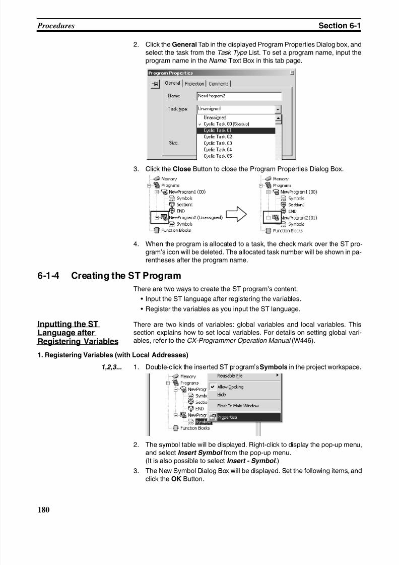
8/11/2019 CX-Programmer V9 Operation Manual FB ST.pdf
http://slidepdf.com/reader/full/cx-programmer-v9-operation-manual-fb-stpdf 206/254
180
Procedures Section 6-1
2. Click the General Tab in the displayed Program Properties Dialog box, andselect the task from the Task Type List. To set a program name, input theprogram name in the Name Text Box in this tab page.
3. Click the Close Button to close the Program Properties Dialog Box.
4. When the program is allocated to a task, the check mark over the ST pro-gram’s icon will be deleted. The allocated task number will be shown in pa-rentheses after the program name.
6-1-4 Creating the ST Program
There are two ways to create the ST program’s content.
• Input the ST language after registering the variables.
• Register the variables as you input the ST language.
Inputting the STLanguage afterRegistering Variables
There are two kinds of variables: global variables and local variables. Thissection explains how to set local variables. For details on setting global vari-ables, refer to the CX-Programmer Operation Manual (W446).
1. Registering Variables (with Local Addresses)
1,2,3... 1. Double-click the inserted ST program’s Symbols in the project workspace.
2. The symbol table will be displayed. Right-click to display the pop-up menu,and select Insert Symbol from the pop-up menu.(It is also possible to select Insert - Symbol .)
3. The New Symbol Dialog Box will be displayed. Set the following items, andclick the OK Button.
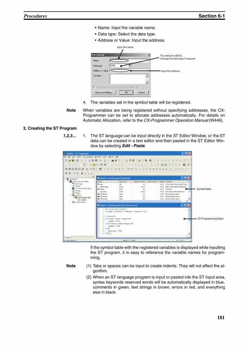
8/11/2019 CX-Programmer V9 Operation Manual FB ST.pdf
http://slidepdf.com/reader/full/cx-programmer-v9-operation-manual-fb-stpdf 207/254
181
Procedures Section 6-1
• Name: Input the variable name.
• Data type: Select the data type.
• Address or Value: Input the address.
4. The variables set in the symbol table will be registered.
Note When variables are being registered without specifying addresses, the CX-Programmer can be set to allocate addresses automatically. For details onAutomatic Allocation, refer to the CX-Programmer Operation Manual (W446).
2. Creating the ST Program
1,2,3... 1. The ST language can be input directly in the ST Editor Window, or the STdata can be created in a text editor and then pasted in the ST Editor Win-dow by selecting Edit - Paste .
If the symbol table with the registered variables is displayed while inputtingthe ST program, it is easy to reference the variable names for program-ming.
Note (1) Tabs or spaces can be input to create indents. They will not affect the al-gorithm.
(2) When an ST language program is input or pasted into the ST input area,syntax keywords reserved words will be automatically displayed in blue,comments in green, text strings in brown, errors in red, and everythingelse in black.
Input the name.
The default is BOOL.Change the data type if required.
Input the address.
Symbol table
ST Programming Editor
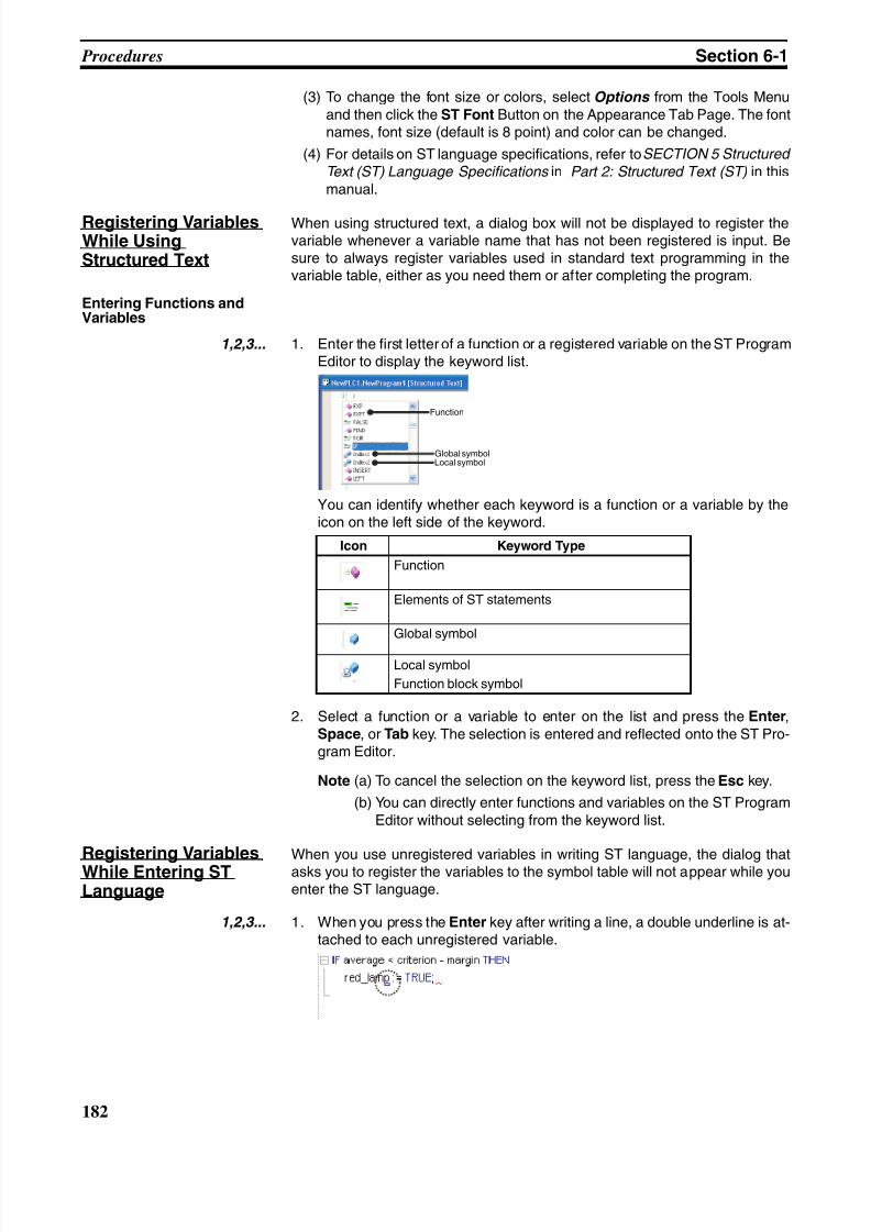
8/11/2019 CX-Programmer V9 Operation Manual FB ST.pdf
http://slidepdf.com/reader/full/cx-programmer-v9-operation-manual-fb-stpdf 208/254
182
Procedures Section 6-1
(3) To change the font size or colors, select Options from the Tools Menuand then click the ST Font Button on the Appearance Tab Page. The fontnames, font size (default is 8 point) and color can be changed.
(4) For details on ST language specifications, refer to SECTION 5 Structured
Text (ST) Language Specifications in Part 2: Structured Text (ST) in thismanual.
Registering VariablesWhile UsingStructured Text
When using structured text, a dialog box will not be displayed to register thevariable whenever a variable name that has not been registered is input. Besure to always register variables used in standard text programming in thevariable table, either as you need them or after completing the program.
Entering Functions andVariables
1,2,3... 1. Enter the first letter of a function or a registered variable on the ST ProgramEditor to display the keyword list.
You can identify whether each keyword is a function or a variable by theicon on the left side of the keyword.
2. Select a function or a variable to enter on the list and press the Enter,Space, or Tab key. The selection is entered and reflected onto the ST Pro-gram Editor.
Note (a) To cancel the selection on the keyword list, press the Esc key.
(b) You can directly enter functions and variables on the ST ProgramEditor without selecting from the keyword list.
Registering VariablesWhile Entering STLanguage
When you use unregistered variables in writing ST language, the dialog thatasks you to register the variables to the symbol table will not appear while youenter the ST language.
1,2,3... 1. When you press the Enter key after writing a line, a double underline is at-tached to each unregistered variable.
Icon Keyword Type
Function
Elements of ST statements
Global symbol
Local symbol
Function block symbol
Function
Global symbolLocal symbol
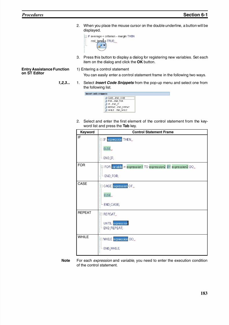
8/11/2019 CX-Programmer V9 Operation Manual FB ST.pdf
http://slidepdf.com/reader/full/cx-programmer-v9-operation-manual-fb-stpdf 209/254
183
Procedures Section 6-1
2. When you place the mouse cursor on the double underline, a button will bedisplayed.
3. Press this button to display a dialog for registering new variables. Set eachitem on the dialog and click the OK button.
Entry Assistance Functionon ST Editor
1) Entering a control statement
You can easily enter a control statement frame in the following two ways.
1,2,3... 1. Select Insert Code Snippets from the pop-up menu and select one fromthe following list.
2. Select and enter the first element of the control statement from the key-word list and press the Tab key.
Note For each expression and variable , you need to enter the execution conditionof the control statement.
Keyword Control Statement Frame
IF
FOR
CASE
REPEAT
WHILE
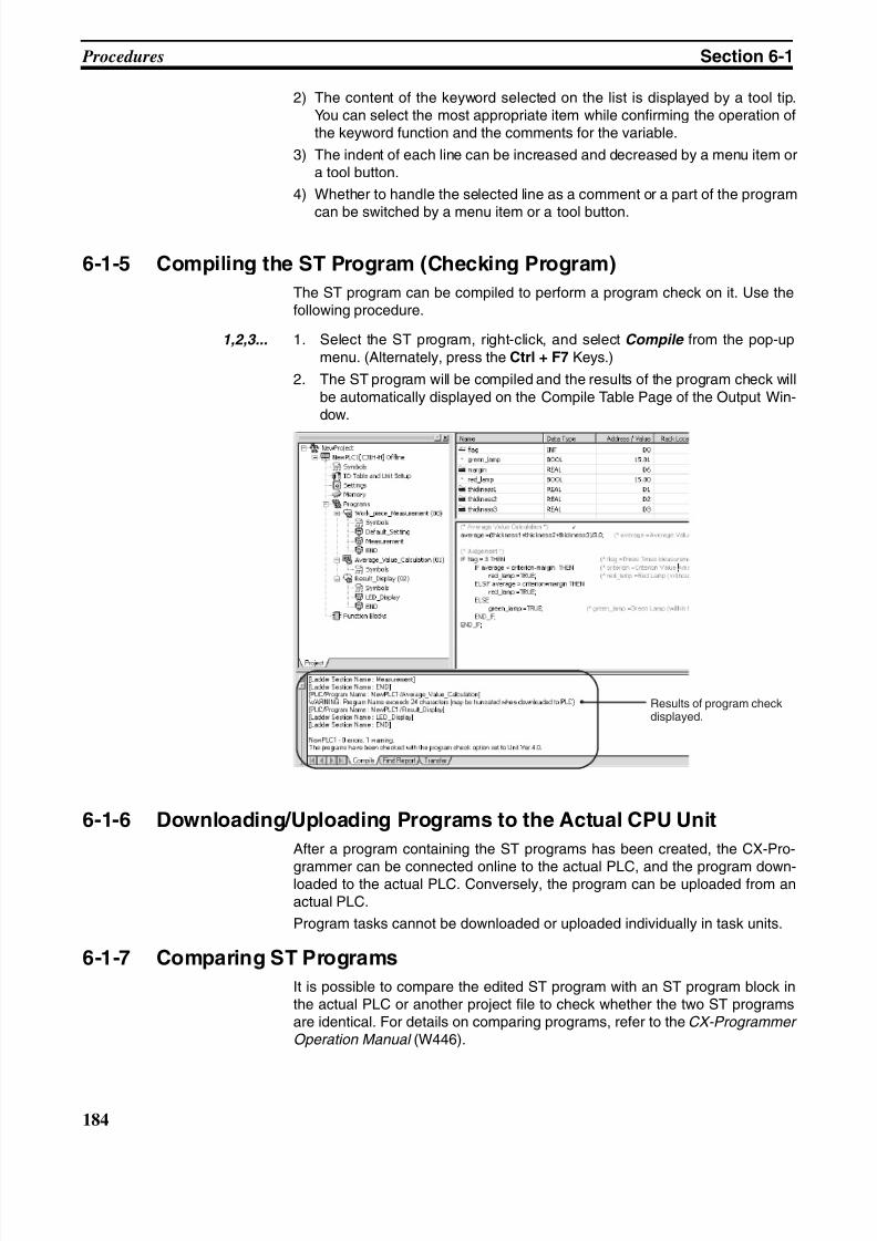
8/11/2019 CX-Programmer V9 Operation Manual FB ST.pdf
http://slidepdf.com/reader/full/cx-programmer-v9-operation-manual-fb-stpdf 210/254
184
Procedures Section 6-1
2) The content of the keyword selected on the list is displayed by a tool tip.You can select the most appropriate item while confirming the operation ofthe keyword function and the comments for the variable.
3) The indent of each line can be increased and decreased by a menu item ora tool button.
4) Whether to handle the selected line as a comment or a part of the program
can be switched by a menu item or a tool button.
6-1-5 Compiling the ST Program (Checking Program)
The ST program can be compiled to perform a program check on it. Use thefollowing procedure.
1,2,3... 1. Select the ST program, right-click, and select Compile from the pop-upmenu. (Alternately, press the Ctrl + F7 Keys.)
2. The ST program will be compiled and the results of the program check willbe automatically displayed on the Compile Table Page of the Output Win-dow.
6-1-6 Downloading/Uploading Programs to the Actual CPU Unit
After a program containing the ST programs has been created, the CX-Pro-
grammer can be connected online to the actual PLC, and the program down-loaded to the actual PLC. Conversely, the program can be uploaded from anactual PLC.
Program tasks cannot be downloaded or uploaded individually in task units.
6-1-7 Comparing ST Programs
It is possible to compare the edited ST program with an ST program block inthe actual PLC or another project file to check whether the two ST programsare identical. For details on comparing programs, refer to the CX-Programmer Operation Manual (W446).
Results of program checkdisplayed.
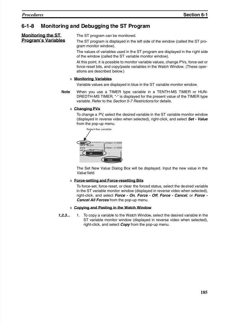
8/11/2019 CX-Programmer V9 Operation Manual FB ST.pdf
http://slidepdf.com/reader/full/cx-programmer-v9-operation-manual-fb-stpdf 211/254
185
Procedures Section 6-1
6-1-8 Monitoring and Debugging the ST Program
Monitoring the STProgram’s Variables
The ST program can be monitored.
The ST program is displayed in the left side of the window (called the ST pro-gram monitor window).
The values of variables used in the ST program are displayed in the right side
of the window (called the ST variable monitor window).At this point, it is possible to monitor variable values, change PVs, force-set orforce-reset bits, and copy/paste variables in the Watch Window. (These oper-ations are described below.)
n Monitoring Variables
Variable values are displayed in blue in the ST variable monitor window.
Note When you use a TIMER type variable in a TENTH-MS TIMER or HUN-DREDTH-MS TIMER, "-" is displayed for the present value of the TIMER typevariable. Refer to the Section 5-7 Restrictions for details.
n Changing PVs
To change a PV, select the desired variable in the ST variable monitor window(displayed in reverse video when selected), right-click, and select Set - Value from the pop-up menu.
The Set New Value Dialog Box will be displayed. Input the new value in theValue field.
n Force-setting and Force-resetting Bits
To force-set, force-reset, or clear the forced status, select the desired variablein the ST variable monitor window (displayed in reverse video when selected),right-click, and select Force - On , Force - Off , Force - Cancel , or Force - Cancel All Forces from the pop-up menu.
n Copying and Pasting in the Watch Window
1,2,3... 1. To copy a variable to the Watch Window, select the desired variable in theST variable monitor window (displayed in reverse video when selected),right-click, and select Copy from the pop-up menu.
Select the variable.
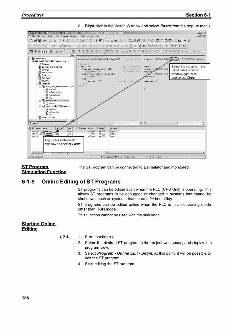
8/11/2019 CX-Programmer V9 Operation Manual FB ST.pdf
http://slidepdf.com/reader/full/cx-programmer-v9-operation-manual-fb-stpdf 212/254
186
Procedures Section 6-1
2. Right-click in the Watch Window and select Paste from the pop-up menu.
ST Program
Simulation Function
The ST program can be connected to a simulator and monitored.
6-1-9 Online Editing of ST Programs
ST programs can be edited even when the PLC (CPU Unit) is operating. Thisallows ST programs to be debugged or changed in systems that cannot beshut down, such as systems that operate 24 hours/day.
ST programs can be edited online when the PLC is in an operating modeother than RUN mode.
This function cannot be used with the simulator.
Starting Online
Editing1,2,3... 1. Start monitoring.
2. Select the desired ST program in the project workspace, and display it inprogram view.
3. Select Program - Online Edit - Begin . At this point, it will be possible toedit the ST program.
4. Start editing the ST program.
Right-click in the WatchWindow and select Paste .
Select the variable in theST variable monitorwindow, right-click,and select Copy .
8/11/2019 CX-Programmer V9 Operation Manual FB ST.pdf
http://slidepdf.com/reader/full/cx-programmer-v9-operation-manual-fb-stpdf 213/254
187
Procedures Section 6-1
Transferring theChanges
1,2,3... 1. After editing is completed, select Program - Online Edit - Send Changes .The Send Changes Dialog Box will be displayed.
2. Select the desired transfer mode and click the OK Button. The edited STprogram will be transferred to the PLC.
For details on the transfer modes, refer to Transfer Modes on page 187 andSelecting a Transfer Mode on page 187.
3. After the transfer is completed, the ST program will return to its previousstatus in which the ST program cannot be edited. If further editing is nec-essary, resume the online editing procedure from the beginning of the pro-cedure (Starting Online Editing).
Cancelling theChanges
To discard the changes made to the ST program, select Program - Online Edit - Cancel . The edited ST program will not be sent to the PLC, and the STprogram will revert to the original status before online editing was started.
Transfer Modes
Standard Mode In Standard Mode, both the ST program’s source code and object code aretransferred to the CPU Unit. Some time may be required for Standard Modetransfers because of the quantity of data that must be sent. Other editing ortransfer operations cannot be performed until the transfer has been com-pleted.
Quick Mode In Quick Mode, only the ST program’s object code is transferred to the CPUUnit. The ST source code is not transferred, making Quick Mode faster thanNormal Mode. After transferring the object code in Quick Mode, either 1)select Program - Transfer SFC/ST Source to PLC to transfer the sourcecode or 2) transfer the source code according to instructions displayed in adialog box when you go offline.
After transferring the object code, a yellow mark will be displayed at the bot-tom of the window until offline status is entered to indicate that the sourcecode has not yet been transferred. This yellow mark will disappear when thesource code is transferred.
Selecting a TransferMode
As a rule, use Standard Mode to transfer ST program changes, unless onlineediting is performed frequently. If too much time is required, increase the baudrate as much as possible before the transfer. If too much time is still requiredand debugging efficiency is hindered by continuous online editing, use QuickMode as an exception, but be sure you understand the restrictions given inthe following note (Mode Restrictions in Quick Mode ).
!Caution Restrictions in Quick Mode (ST Source Code Not Transferred)When the ST program’s ST source code is not being transferred, the CX-Pro-grammer cannot upload the program correctly the next time.Consequently, after the ST program’s online editing changes have been trans-ferred in Quick Mode, it may be impossible to upload the program later (seenote) if the computer or CX-Programmer crashes before the source code canbe transferred.
Note It may be still be possible to transfer the source code with the following proce-dure, even if the above problem occurs.
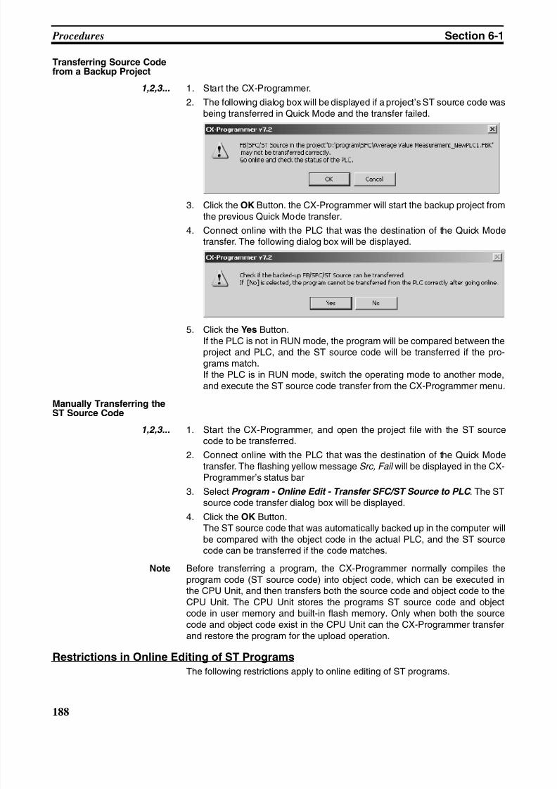
8/11/2019 CX-Programmer V9 Operation Manual FB ST.pdf
http://slidepdf.com/reader/full/cx-programmer-v9-operation-manual-fb-stpdf 214/254
188
Procedures Section 6-1
Transferring Source Codefrom a Backup Project
1,2,3... 1. Start the CX-Programmer.
2. The following dialog box will be displayed if a project’s ST source code wasbeing transferred in Quick Mode and the transfer failed.
3. Click the OK Button. the CX-Programmer will start the backup project fromthe previous Quick Mode transfer.
4. Connect online with the PLC that was the destination of the Quick Modetransfer. The following dialog box will be displayed.
5. Click the Yes Button.If the PLC is not in RUN mode, the program will be compared between theproject and PLC, and the ST source code will be transferred if the pro-grams match.If the PLC is in RUN mode, switch the operating mode to another mode,and execute the ST source code transfer from the CX-Programmer menu.
Manually Transferring the
ST Source Code1,2,3... 1. Start the CX-Programmer, and open the project file with the ST source
code to be transferred.
2. Connect online with the PLC that was the destination of the Quick Modetransfer. The flashing yellow message Src, Fail will be displayed in the CX-Programmer’s status bar
3. Select Program - Online Edit - Transfer SFC/ST Source to PLC . The STsource code transfer dialog box will be displayed.
4. Click the OK Button.The ST source code that was automatically backed up in the computer willbe compared with the object code in the actual PLC, and the ST source
code can be transferred if the code matches.Note Before transferring a program, the CX-Programmer normally compiles the
program code (ST source code) into object code, which can be executed inthe CPU Unit, and then transfers both the source code and object code to theCPU Unit. The CPU Unit stores the programs ST source code and objectcode in user memory and built-in flash memory. Only when both the sourcecode and object code exist in the CPU Unit can the CX-Programmer transferand restore the program for the upload operation.
Restrictions in Online Editing of ST Programs
The following restrictions apply to online editing of ST programs.
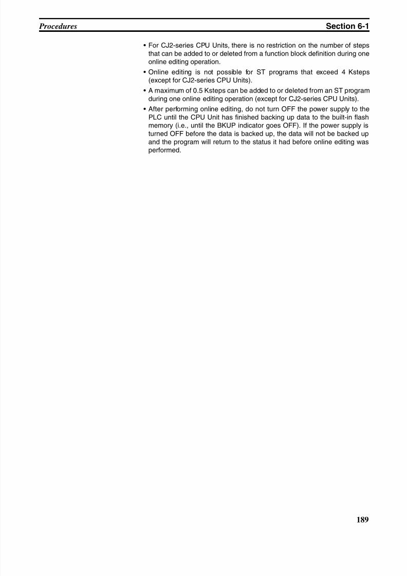
8/11/2019 CX-Programmer V9 Operation Manual FB ST.pdf
http://slidepdf.com/reader/full/cx-programmer-v9-operation-manual-fb-stpdf 215/254
189
Procedures Section 6-1
• For CJ2-series CPU Units, there is no restriction on the number of stepsthat can be added to or deleted from a function block definition during oneonline editing operation.
• Online editing is not possible for ST programs that exceed 4 Ksteps(except for CJ2-series CPU Units).
• A maximum of 0.5 Ksteps can be added to or deleted from an ST program
during one online editing operation (except for CJ2-series CPU Units).• After performing online editing, do not turn OFF the power supply to the
PLC until the CPU Unit has finished backing up data to the built-in flashmemory (i.e., until the BKUP indicator goes OFF). If the power supply isturned OFF before the data is backed up, the data will not be backed upand the program will return to the status it had before online editing wasperformed.

8/11/2019 CX-Programmer V9 Operation Manual FB ST.pdf
http://slidepdf.com/reader/full/cx-programmer-v9-operation-manual-fb-stpdf 216/254
190
Procedures Section 6-1
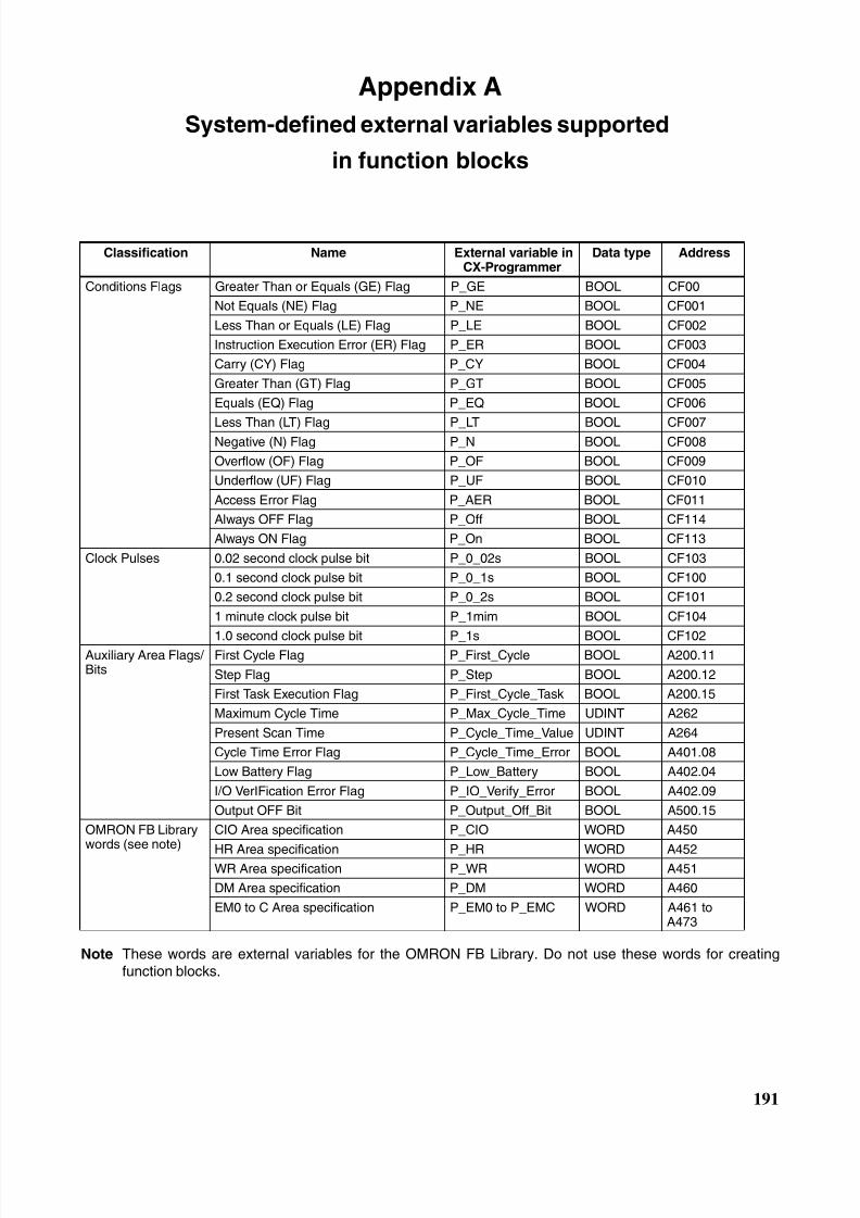
8/11/2019 CX-Programmer V9 Operation Manual FB ST.pdf
http://slidepdf.com/reader/full/cx-programmer-v9-operation-manual-fb-stpdf 217/254
191
Appendix A
System-defined external variables supported
in function blocks
Note These words are external variables for the OMRON FB Library. Do not use these words for creatingfunction blocks.
Classification Name External variable inCX-Programmer
Data type Address
Conditions Flags Greater Than or Equals (GE) Flag P_GE BOOL CF00
Not Equals (NE) Flag P_NE BOOL CF001
Less Than or Equals (LE) Flag P_LE BOOL CF002
Instruction Execution Error (ER) Flag P_ER BOOL CF003
Carry (CY) Flag P_CY BOOL CF004
Greater Than (GT) Flag P_GT BOOL CF005
Equals (EQ) Flag P_EQ BOOL CF006
Less Than (LT) Flag P_LT BOOL CF007Negative (N) Flag P_N BOOL CF008
Overflow (OF) Flag P_OF BOOL CF009
Underflow (UF) Flag P_UF BOOL CF010
Access Error Flag P_AER BOOL CF011
Always OFF Flag P_Off BOOL CF114
Always ON Flag P_On BOOL CF113
Clock Pulses 0.02 second clock pulse bit P_0_02s BOOL CF103
0.1 second clock pulse bit P_0_1s BOOL CF100
0.2 second clock pulse bit P_0_2s BOOL CF101
1 minute clock pulse bit P_1mim BOOL CF104
1.0 second clock pulse bit P_1s BOOL CF102Auxiliary Area Flags/ Bits
First Cycle Flag P_First_Cycle BOOL A200.11
Step Flag P_Step BOOL A200.12
First Task Execution Flag P_First_Cycle_Task BOOL A200.15
Maximum Cycle Time P_Max_Cycle_Time UDINT A262
Present Scan Time P_Cycle_Time_Value UDINT A264
Cycle Time Error Flag P_Cycle_Time_Error BOOL A401.08
Low Battery Flag P_Low_Battery BOOL A402.04
I/O VerIFication Error Flag P_IO_Verify_Error BOOL A402.09
Output OFF Bit P_Output_Off_Bit BOOL A500.15
OMRON FB Librarywords (see note)
CIO Area specification P_CIO WORD A450
HR Area specification P_HR WORD A452WR Area specification P_WR WORD A451
DM Area specification P_DM WORD A460
EM0 to C Area specification P_EM0 to P_EMC WORD A461 toA473
8/11/2019 CX-Programmer V9 Operation Manual FB ST.pdf
http://slidepdf.com/reader/full/cx-programmer-v9-operation-manual-fb-stpdf 218/254
192
System-defined external variables supported in function blocks Appendix A
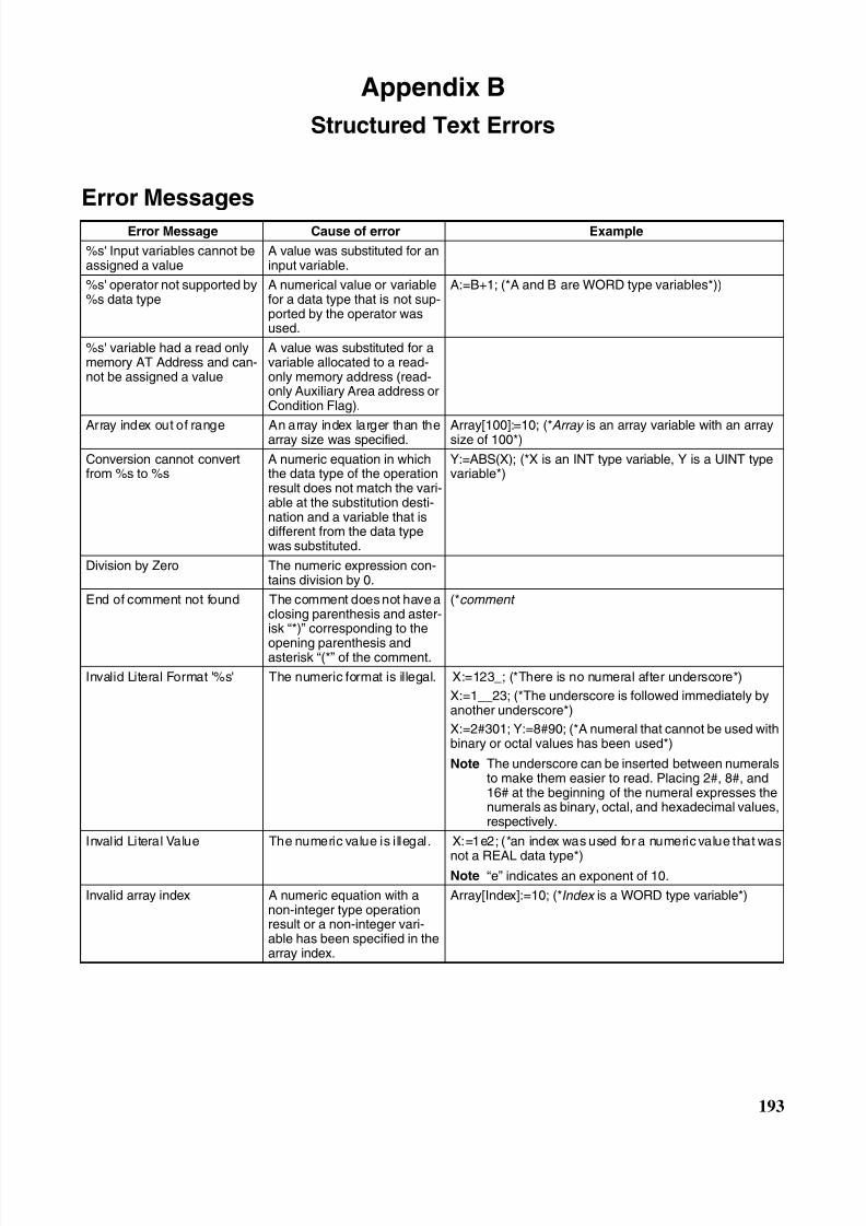
8/11/2019 CX-Programmer V9 Operation Manual FB ST.pdf
http://slidepdf.com/reader/full/cx-programmer-v9-operation-manual-fb-stpdf 219/254
193
Appendix B
Structured Text Errors
Error Messages
Error Message Cause of error Example
%s' Input variables cannot beassigned a value
A value was substituted for aninput variable.
%s' operator not supported by%s data type
A numerical value or variablefor a data type that is not sup-ported by the operator wasused.
A:=B+1; (*A and B are WORD type variables*))
%s' variable had a read onlymemory AT Address and can-not be assigned a value
A value was substituted for avariable allocated to a read-only memory address (read-only Auxiliary Area address orCondition Flag).
Array index out of range An array index larger than thearray size was specified. Array[100]:=10; (*Array is an array variable with an arraysize of 100*)
Conversion cannot convertfrom %s to %s
A numeric equation in whichthe data type of the operationresult does not match the vari-able at the substitution desti-nation and a variable that isdifferent from the data typewas substituted.
Y:=ABS(X); (*X is an INT type variable, Y is a UINT typevariable*)
Division by Zero The numeric expression con-tains division by 0.
End of comment not found The comment does not have aclosing parenthesis and aster-isk “*)” corresponding to the
opening parenthesis andasterisk “(*” of the comment.
(*comment
Invalid Literal Format '%s' The numeric format is illegal. X:=123_; (*There is no numeral after underscore*)
X:=1__23; (*The underscore is followed immediately byanother underscore*)
X:=2#301; Y:=8#90; (*A numeral that cannot be used withbinary or octal values has been used*)
Note The underscore can be inserted between numeralsto make them easier to read. Placing 2#, 8#, and16# at the beginning of the numeral expresses thenumerals as binary, octal, and hexadecimal values,respectively.
Invalid Literal Value The numeric value is illegal. X:=1e2; (*an index was used for a numeric value that was
not a REAL data type*)Note “e” indicates an exponent of 10.
Invalid array index A numeric equation with anon-integer type operationresult or a non-integer vari-able has been specified in thearray index.
Array[Index]:=10; (*Index is a WORD type variable*)
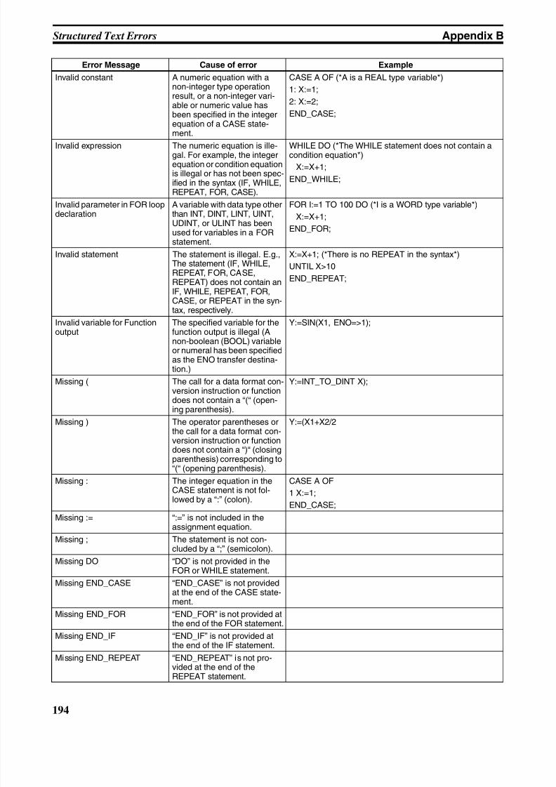
8/11/2019 CX-Programmer V9 Operation Manual FB ST.pdf
http://slidepdf.com/reader/full/cx-programmer-v9-operation-manual-fb-stpdf 220/254
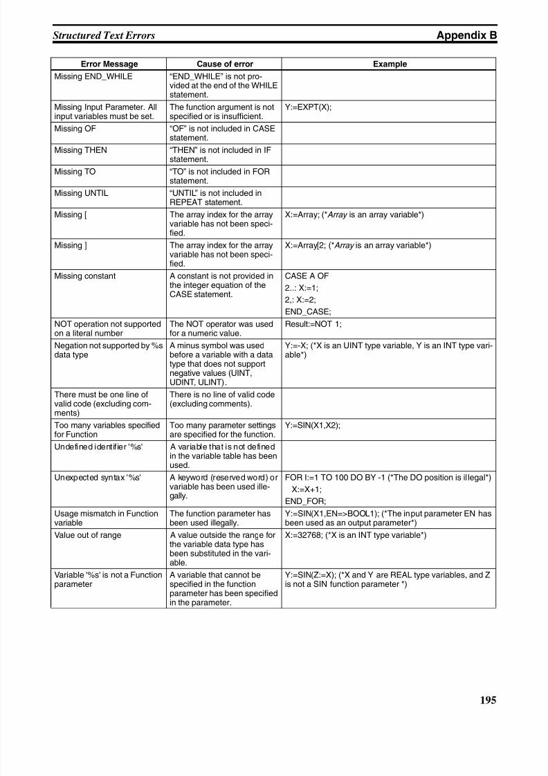
8/11/2019 CX-Programmer V9 Operation Manual FB ST.pdf
http://slidepdf.com/reader/full/cx-programmer-v9-operation-manual-fb-stpdf 221/254
195
Structured Text Errors Appendix B
Missing END_WHILE “END_WHILE” is not pro-vided at the end of the WHILEstatement.
Missing Input Parameter. Allinput variables must be set.
The function argument is notspecified or is insufficient.
Y:=EXPT(X);
Missing OF “OF” is not included in CASE
statement.
Missing THEN “THEN” is not included in IFstatement.
Missing TO “TO” is not included in FORstatement.
Missing UNTIL “UNTIL” is not included inREPEAT statement.
Missing [ The array index for the arrayvariable has not been speci-fied.
X:=Array; (*Array is an array variable*)
Missing ] The array index for the arrayvariable has not been speci-fied.
X:=Array[2; (*Array is an array variable*)
Missing constant A constant is not provided inthe integer equation of theCASE statement.
CASE A OF
2..: X:=1;
2,: X:=2;
END_CASE;
NOT operation not supportedon a literal number
The NOT operator was usedfor a numeric value.
Result:=NOT 1;
Negation not supported by %sdata type
A minus symbol was usedbefore a variable with a datatype that does not supportnegative values (UINT,UDINT, ULINT).
Y:=-X; (*X is an UINT type variable, Y is an INT type vari-able*)
There must be one line of
valid code (excluding com-ments)
There is no line of valid code
(excluding comments).
Too many variables specifiedfor Function
Too many parameter settingsare specified for the function.
Y:=SIN(X1,X2);
Undefined identifier '%s' A variable that is not definedin the variable table has beenused.
Unexpected syntax '%s' A keyword (reserved word) orvariable has been used ille-gally.
FOR I:=1 TO 100 DO BY -1 (*The DO position is il legal*)
X:=X+1;
END_FOR;
Usage mismatch in Functionvariable
The function parameter hasbeen used illegally.
Y:=SIN(X1,EN=>BOOL1); (*The input parameter EN hasbeen used as an output parameter*)
Value out of range A value outside the range for
the variable data type hasbeen substituted in the vari-able.
X:=32768; (*X is an INT type variable*)
Variable '%s' is not a Functionparameter
A variable that cannot bespecified in the functionparameter has been specifiedin the parameter.
Y:=SIN(Z:=X); (*X and Y are REAL type variables, and Zis not a SIN function parameter *)
Error Message Cause of error Example
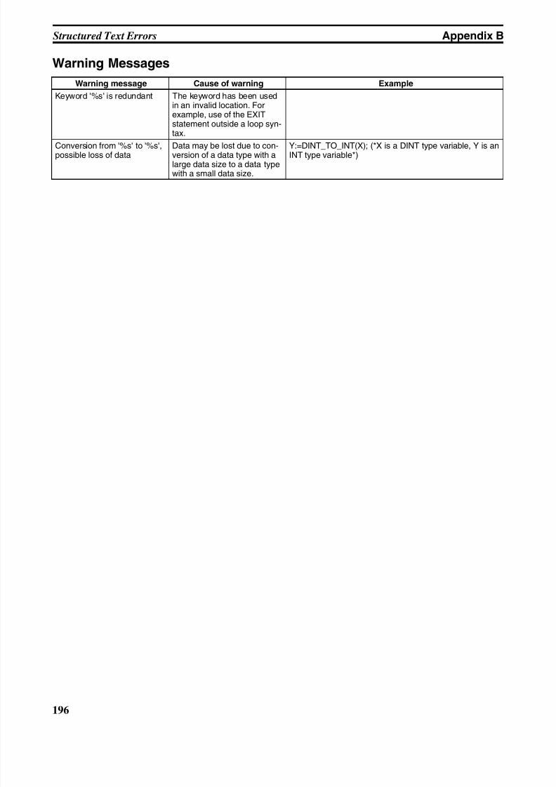
8/11/2019 CX-Programmer V9 Operation Manual FB ST.pdf
http://slidepdf.com/reader/full/cx-programmer-v9-operation-manual-fb-stpdf 222/254
196
Structured Text Errors Appendix B
Warning Messages
Warning message Cause of warning Example
Keyword '%s' is redundant The keyword has been usedin an invalid location. Forexample, use of the EXITstatement outside a loop syn-
tax.Conversion from '%s' to '%s',possible loss of data
Data may be lost due to con-version of a data type with alarge data size to a data typewith a small data size.
Y:=DINT_TO_INT(X); (*X is a DINT type variable, Y is anINT type variable*)
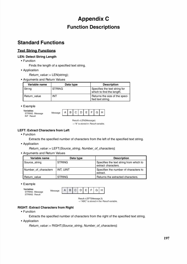
8/11/2019 CX-Programmer V9 Operation Manual FB ST.pdf
http://slidepdf.com/reader/full/cx-programmer-v9-operation-manual-fb-stpdf 223/254
197
Appendix C
Function Descriptions
Standard Functions
Text String Functions
LEN: Detect String Length
• Function
Finds the length of a specified text string.
• Application
Return_value := LEN(string);
• Arguments and Return Values
• Example
LEFT: Extract Characters from Left
• Function
Extracts the specified number of characters from the left of the specified text string.• Application
Return_value := LEFT(Source_string, Number_of_characters) ;
• Arguments and Return Values
• Example
RIGHT: Extract Characters from Right
• Function
Extracts the specified number of characters from the right of the specified text string.
• Application
Return_value := RIGHT(Source_string, Number_of_characters) ;
Variable name Data type Description
String STRING Specifies the text string for
which to find the length.Return_value INT Returns the size of the speci-
fied text string.
Variable name Data type Description
Source_string STRING Specifies the text string from which toextract characters.
Number_of_characters INT, UINT Specifies the number of characters toextract.
Return_value STRING Returns the extracted characters.
A B C D E F G HVariables
STRING Message INT Result
Message
Result:=LEN(Message);
→ "8" is stored in Result variable.
A B C D E F G HMessageVariables
STRING Message STRING Result
Result:=LEFT(Message,3);→ "ABC" is stored in the Result variable.
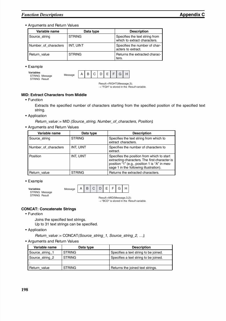
8/11/2019 CX-Programmer V9 Operation Manual FB ST.pdf
http://slidepdf.com/reader/full/cx-programmer-v9-operation-manual-fb-stpdf 224/254
198
Function Descriptions Appendix C
• Arguments and Return Values
• Example
MID: Extract Characters from Middle
• Function
Extracts the specified number of characters starting from the specified position of the specified textstring.
• Application
Return_value := MID (Source_string, Number_of_characters, Position) ;
• Arguments and Return Values
• Example
CONCAT: Concatenate Strings
• Function
Joins the specified text strings.
Up to 31 text strings can be specified.• Application
Return_value := CONCAT(Source_string_1, Source_string_2, …) ;
• Arguments and Return Values
Variable name Data type Description
Source_string STRING Specifies the text string fromwhich to extract characters.
Number_of_characters INT, UINT Specifies the number of char-acters to extract.
Return_value STRING Returns the extracted charac-ters.
Variable name Data type Description
Source_string STRING Specifies the text string from which toextract characters.
Number_of_characters INT, UINT Specifies the number of characters toextract.
Position INT, UINT Specifies the position from which to startextracting characters. The first character isposition “1” (e.g., position 1 is “A” in mes-
sage 1 in the following illustration).Return_value STRING Returns the extracted characters.
Variable name Data type Description
Source_string_1 STRING Specifies a text string to be joined.
Source_string_2 STRING Specifies a text string to be joined.
:
Return_value STRING Returns the joined text strings.
A B C D E F G HMessageVariables
STRING Message STRING Result
Result:=RIGHT(Message,3);→ "FGH" is stored in the Result variable.
MessageVariables
STRING Message STRING Result
Result:=MID(Message,3,2);→ "BCD" is stored in the Result variable.
A B C D E F G H
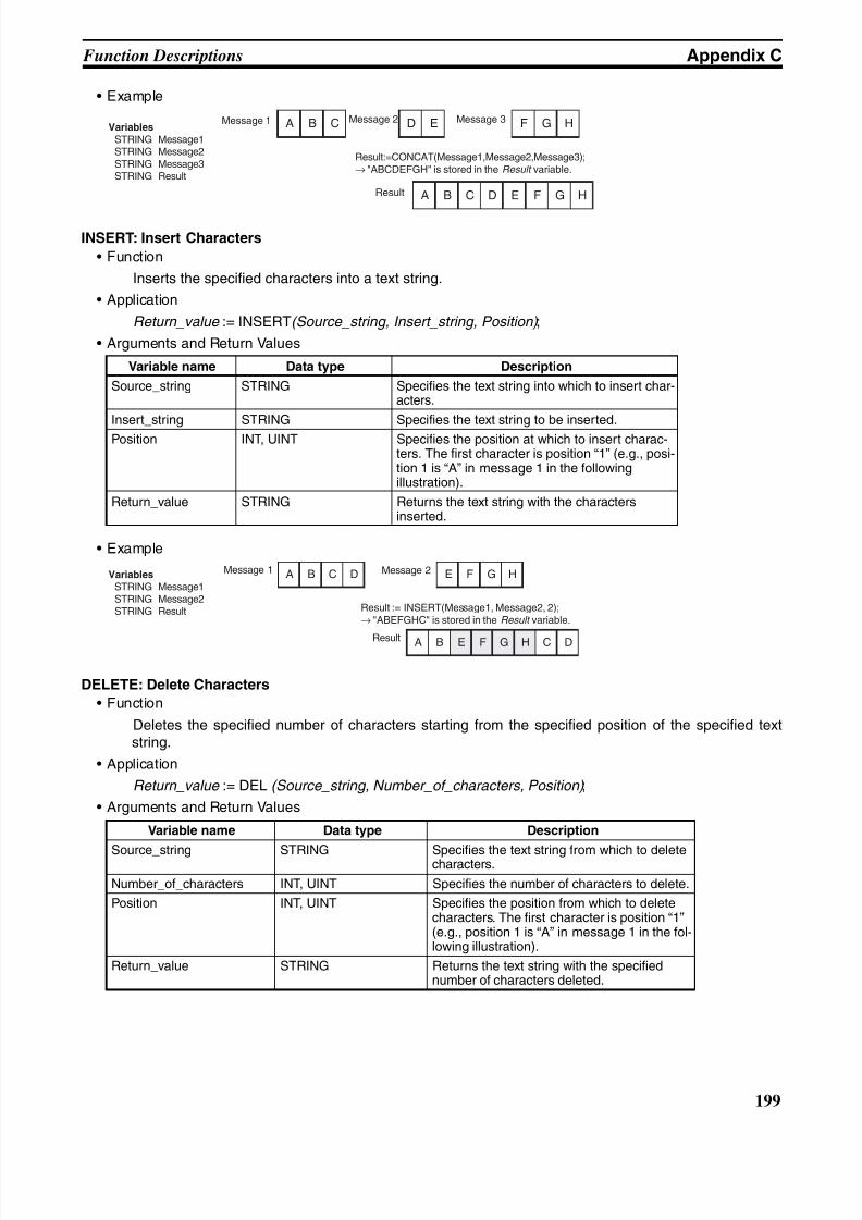
8/11/2019 CX-Programmer V9 Operation Manual FB ST.pdf
http://slidepdf.com/reader/full/cx-programmer-v9-operation-manual-fb-stpdf 225/254
199
Function Descriptions Appendix C
• Example
INSERT: Insert Characters
• Function
Inserts the specified characters into a text string.
• Application
Return_value := INSERT(Source_string, Insert_string, Position) ;
• Arguments and Return Values
• Example
DELETE: Delete Characters
• Function
Deletes the specified number of characters starting from the specified position of the specified textstring.
• Application
Return_value := DEL (Source_string, Number_of_characters, Position) ;
• Arguments and Return Values
Variable name Data type Description
Source_string STRING Specifies the text string into which to insert char-acters.
Insert_string STRING Specifies the text string to be inserted.
Position INT, UINT Specifies the position at which to insert charac-ters. The first character is position “1” (e.g., posi-tion 1 is “A” in message 1 in the followingillustration).
Return_value STRING Returns the text string with the charactersinserted.
Variable name Data type Description
Source_string STRING Specifies the text string from which to deletecharacters.
Number_of_characters INT, UINT Specifies the number of characters to delete.
Position INT, UINT Specifies the position from which to deletecharacters. The first character is position “1”(e.g., position 1 is “A” in message 1 in the fol-lowing illustration).
Return_value STRING Returns the text string with the specifiednumber of characters deleted.
Message 1Variables
STRING Message1 STRING Message2 STRING Message3 STRING Result
Result:=CONCAT(Message1,Message2,Message3);→ "ABCDEFGH" is stored in the Result variable.
A B C D E F G H
A B C D E F G H
Message 2 Message 3
Result
Message 1Variables
STRING Message1 STRING Message2 STRING Result Result := INSERT(Message1, Message2, 2);
→ "ABEFGHC" is stored in the Result variable.
Message 2
Result
A B C D E F G H
A B C DE F G H
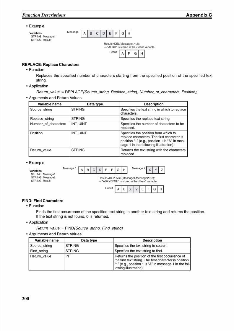
8/11/2019 CX-Programmer V9 Operation Manual FB ST.pdf
http://slidepdf.com/reader/full/cx-programmer-v9-operation-manual-fb-stpdf 226/254
200
Function Descriptions Appendix C
• Example
REPLACE: Replace Characters
• Function
Replaces the specified number of characters starting from the specified position of the specified textstring.
• Application
Return_value := REPLACE(Source_string, Replace_string, Number_of_characters, Position) ;
• Arguments and Return Values
• Example
FIND: Find Characters
• Function
Finds the first occurrence of the specified text string in another text string and returns the position.If the text string is not found, 0 is returned.
• Application
Return_value := FIND(Source_string, Find_string) ;
• Arguments and Return Values
Variable name Data type Description
Source_string STRING Specifies the text string in which to replacecharacters.
Replace_string STRING Specifies the replace text string.
Number_of_characters INT, UINT Specifies the number of characters to bereplaced.
Position INT, UINT Specifies the position from which toreplace characters. The first character isposition “1” (e.g., position 1 is “A” in mes-sage 1 in the following illustration).
Return_value STRING Returns the text string with the charactersreplaced.
Variable name Data type Description
Source_string STRING Specifies the text string to search.
Find_string STRING Specifies the text string to find.
Return_value INT Returns the position of the first occurrence ofthe find text string. The first character is position“1” (e.g., position 1 is “A” in message 1 in the fol-lowing illustration).
MessageVariables
STRING Message1 STRING Result
Result:=DEL(Message1,4,2);→ "AFGH" is stored in the Result variable.
Result
A B C D E F G H
A F G H
Message 1Variables
STRING Message1 STRING Message2 STRING Result
Result:=REPLACE(Message1,Message2,2,3);→ "ABXYEFGH" is stored in the Result variable.
Result
A B C D E F G H
A B X Y E F G H
X Y Z
Message 2
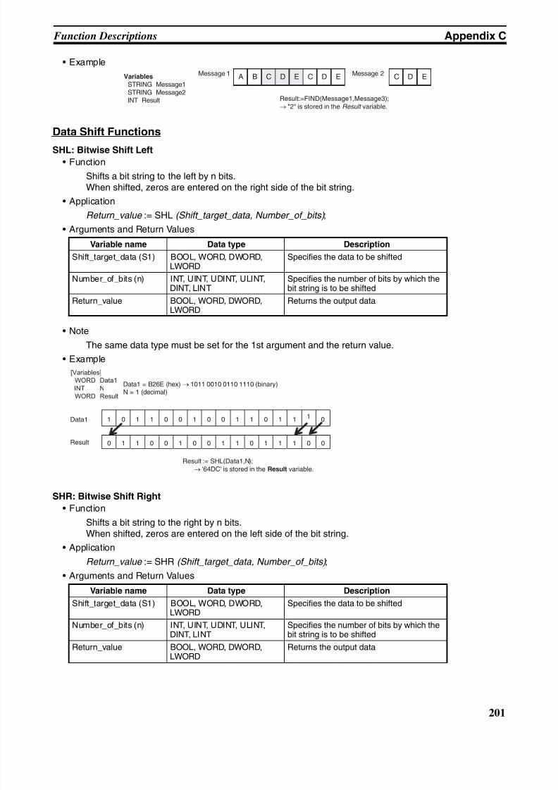
8/11/2019 CX-Programmer V9 Operation Manual FB ST.pdf
http://slidepdf.com/reader/full/cx-programmer-v9-operation-manual-fb-stpdf 227/254
201
Function Descriptions Appendix C
• Example
Data Shift Functions
SHL: Bitwise Shift Left
• Function
Shifts a bit string to the left by n bits.When shifted, zeros are entered on the right side of the bit string.
• Application
Return_value := SHL (Shift_target_data, Number_of_bits) ;
• Arguments and Return Values
• Note
The same data type must be set for the 1st argument and the return value.
• Example
SHR: Bitwise Shift Right
• Function
Shifts a bit string to the right by n bits.When shifted, zeros are entered on the left side of the bit string.
• Application
Return_value := SHR (Shift_target_data, Number_of_bits) ;
• Arguments and Return Values
Variable name Data type Description
Shift_target_data (S1) BOOL, WORD, DWORD,LWORD
Specifies the data to be shifted
Number_of_bits (n) INT, UINT, UDINT, ULINT,DINT, LINT
Specifies the number of bits by which thebit string is to be shifted
Return_value BOOL, WORD, DWORD,LWORD
Returns the output data
Variable name Data type Description
Shift_target_data (S1) BOOL, WORD, DWORD,LWORD
Specifies the data to be shifted
Number_of_bits (n) INT, UINT, UDINT, ULINT,DINT, LINT
Specifies the number of bits by which thebit string is to be shifted
Return_value BOOL, WORD, DWORD,LWORD
Returns the output data
Message 1Variables
STRING Message1 STRING Message2 INT Result Result:=FIND(Message1,Message3);
→ "2" is stored in the Result variable.
Message 2A B C D E C D E C D E
1 0 1 1 0 0 1 0 0 1 1 0 1 1 1 0
0 1 1 0 0 1 0 0 1 1 0 1 1 1 0 0
Data1
Result
Result := SHL(Data1,N); → '64DC' is stored in the Result variable.
Data1 = B26E (hex) → 1011 0010 0110 1110 (binary)N = 1 (decimal)
[Variables]
WORD Data1
INT N
WORD Result
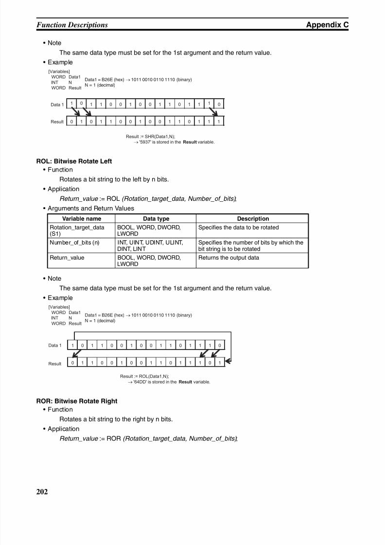
8/11/2019 CX-Programmer V9 Operation Manual FB ST.pdf
http://slidepdf.com/reader/full/cx-programmer-v9-operation-manual-fb-stpdf 228/254
202
Function Descriptions Appendix C
• Note
The same data type must be set for the 1st argument and the return value.
• Example
ROL: Bitwise Rotate Left
• Function
Rotates a bit string to the left by n bits.
• ApplicationReturn_value := ROL (Rotation_target_data, Number_of_bits) ;
• Arguments and Return Values
• Note
The same data type must be set for the 1st argument and the return value.
• Example
ROR: Bitwise Rotate Right
• Function
Rotates a bit string to the right by n bits.
• Application
Return_value := ROR (Rotation_target_data, Number_of_bits) ;
Variable name Data type Description
Rotation_target_data(S1)
BOOL, WORD, DWORD,LWORD
Specifies the data to be rotated
Number_of_bits (n) INT, UINT, UDINT, ULINT,DINT, LINT
Specifies the number of bits by which thebit string is to be rotated
Return_value BOOL, WORD, DWORD,LWORD
Returns the output data
1 0 1 1 0 0 1 0 0 1 1 0 1 1 1 0
0 1 0 1 1 0 0 1 0 0 1 1 0 1 1 1
Data 1
Result
Result := SHR(Data1,N);
→ '5937' is stored in the Result variable.
Data1 = B26E (hex) → 1011 0010 0110 1110 (binary)N = 1 (decimal)
[Variables]
WORD Data1
INT N
WORD Result
1 0 1 1 0 0 1 0 0 1 1 0 1 1 1 0
0 1 1 0 0 1 0 0 1 1 0 1 1 1 0 1
Data 1
Result
Result := ROL(Data1,N);
→ '64DD' is stored in the Result variable.
Data1 = B26E (hex) → 1011 0010 0110 1110 (binary)N = 1 (decimal)
[Variables]
WORD Data1
INT N
WORD Result
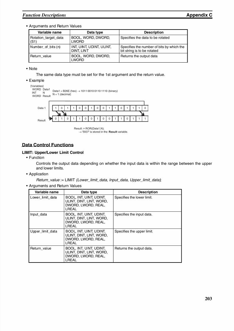
8/11/2019 CX-Programmer V9 Operation Manual FB ST.pdf
http://slidepdf.com/reader/full/cx-programmer-v9-operation-manual-fb-stpdf 229/254
203
Function Descriptions Appendix C
• Arguments and Return Values
• Note
The same data type must be set for the 1st argument and the return value.
• Example
Data Control Functions
LIMIT: Upper/Lower Limit Control
• Function
Controls the output data depending on whether the input data is within the range between the upperand lower limits.
• ApplicationReturn_value := LIMIT (Lower_limit_data, Input_data, Upper_limit_data) ;
• Arguments and Return Values
Variable name Data type Description
Rotation_target_data(S1)
BOOL, WORD, DWORD,LWORD
Specifies the data to be rotated
Number_of_bits (n) INT, UINT, UDINT, ULINT,DINT, LINT
Specifies the number of bits by which thebit string is to be rotated
Return_value BOOL, WORD, DWORD,LWORD Returns the output data
Variable name Data type Description
Lower_limit_data BOOL, INT, UINT, UDINT,ULINT, DINT, LINT, WORD,DWORD, LWORD, REAL,LREAL
Specifies the lower limit.
Input_data BOOL, INT, UINT, UDINT,ULINT, DINT, LINT, WORD,DWORD, LWORD, REAL,LREAL
Specifies the input data.
Upper_limit_data BOOL, INT, UINT, UDINT,ULINT, DINT, LINT, WORD,DWORD, LWORD, REAL,LREAL
Specifies the upper limit.
Return_value BOOL, INT, UINT, UDINT,ULINT, DINT, LINT, WORD,DWORD, LWORD, REAL,LREAL
Returns the output data.
1 0 1 1 0 0 1 0 0 1 1 0 1 1 1 0
0 1 0 1 1 0 0 1 0 0 1 1 0 1 1 1
Data 1
Result
Result := ROR(Data1,N);
→ '5937' is stored in the Result variable.
Data1 = B26E (hex) → 1011 0010 0110 1110 (binary)N = 1 (decimal)
[Variables]
WORD Data1
INT N
WORD Result
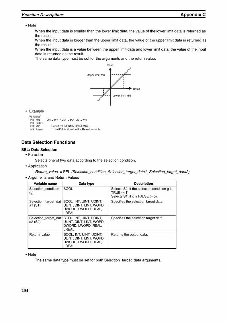
8/11/2019 CX-Programmer V9 Operation Manual FB ST.pdf
http://slidepdf.com/reader/full/cx-programmer-v9-operation-manual-fb-stpdf 230/254
204
Function Descriptions Appendix C
• Note
When the input data is smaller than the lower limit data, the value of the lower limit data is returned asthe result.When the input data is bigger than the upper limit data, the value of the upper limit data is returned asthe result.When the input data is a value between the upper limit data and lower limit data, the value of the inputdata is returned as the result.The same data type must be set for the arguments and the return value.
• Example
Data Selection Functions
SEL: Data Selection
• Function
Selects one of two data according to the selection condition.
• Application
Return_value := SEL (Selection_condition, Selection_target_data1, Selection_target_data2) ;
• Arguments and Return Values
• Note
The same data type must be set for both Selection_target_data arguments.
Variable name Data type Description
Selection_condition(g)
BOOL Selects S2, if the selection condition g isTRUE (= 1).Selects S1, if it is FALSE (= 0).
Selection_target_data1 (S1)
BOOL, INT, UINT, UDINT,ULINT, DINT, LINT, WORD,DWORD, LWORD, REAL,LREAL
Specifies the selection target data.
Selection_target_data2 (S2)
BOOL, INT, UINT, UDINT,ULINT, DINT, LINT, WORD,
DWORD, LWORD, REAL,LREAL
Specifies the selection target data.
Return_value BOOL, INT, UINT, UDINT,ULINT, DINT, LINT, WORD,DWORD, LWORD, REAL,LREAL
Returns the output data.
Data1
Lower limit: MN
Upper limit: MX
Result
[Variables]
INT MN
INT Data1
INT MX
INT Result
MN = 123 Data1 = 456 MX = 789
Result := LIMIT(MN,Data1,MX);
→'456' is stored in the Result variable.
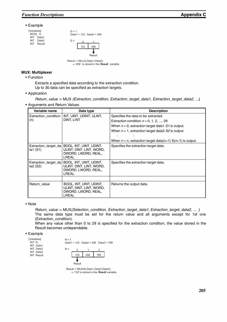
8/11/2019 CX-Programmer V9 Operation Manual FB ST.pdf
http://slidepdf.com/reader/full/cx-programmer-v9-operation-manual-fb-stpdf 231/254
205
Function Descriptions Appendix C
• Example
MUX: Multiplexer
• Function
Extracts a specified data according to the extraction condition.Up to 30 data can be specified as extraction targets.
• Application
Return_value := MUX (Extraction_condition, Extraction_target_data1, Extraction_target_data2, ...) ;
• Arguments and Return Values
• Note
Return_value := MUX(Selection_condition, Extraction_target_data1, Extraction_target_data2, ... ) ;The same data type must be set for the return value and all arguments except for 1st one(Extraction_condition).When any value other than 0 to 29 is specified for the extraction condition, the value stored in theResult becomes undependable.
• Example
Variable name Data type Description
Extraction_condition(n)
INT, UINT, UDINT, ULINT,DINT, LINT
Specifies the data to be extracted.
Extraction condition n = 0, 1, 2, ..., 29
When n = 0, extraction target data1 S1 is output.
When n = 1, extraction target data2 S2 is output.
: :
When n = n, extraction target data(n+1) S(n +1) is output.
Extraction_target_data1 (S1)
BOOL, INT, UINT, UDINT,ULINT, DINT, LINT, WORD,DWORD, LWORD, REAL,LREAL
Specifies the extraction target data.
Extraction_target_data2 (S2)
BOOL, INT, UINT, UDINT,ULINT, DINT, LINT, WORD,
DWORD, LWORD, REAL,LREAL
Specifies the extraction target data.
:
Return_value BOOL, INT, UINT, UDINT,ULINT, DINT, LINT, WORD,DWORD, LWORD, REAL,LREAL
Returns the output data.
Result := SEL(G,Data1,Data2);
→ ‘456’ is stored in the Result variable.
[Variables]
BOOL G
INT Data1
INT Data2
INT Result
G = 1
Data1 = 123 Data2 = 456
G =
123 456
0 1
Result
[Variables]
INT N
INT Data1
INT Data2
INT Data3
INT Result
N = 0Data1 = 123 Data2 = 456 Data3 = 789
N =
789123 456
0 21
Result
Result := MUX(N,Data1,Data2,Data3);
→ '123' is stored in the Result variable.
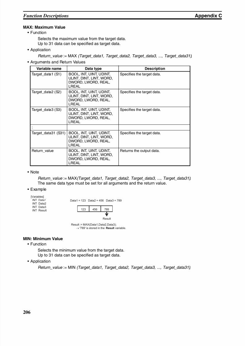
8/11/2019 CX-Programmer V9 Operation Manual FB ST.pdf
http://slidepdf.com/reader/full/cx-programmer-v9-operation-manual-fb-stpdf 232/254
206
Function Descriptions Appendix C
MAX: Maximum Value
• Function
Selects the maximum value from the target data.Up to 31 data can be specified as target data.
• Application
Return_value := MAX (Target_data1, Target_data2, Target_data3, ..., Target_data31) ;
• Arguments and Return Values
• Note
Return_value := MAX(Target_data1, Target_data2, Target_data3, ..., Target_data31) ;
The same data type must be set for all arguments and the return value.
• Example
MIN: Minimum Value
• Function
Selects the minimum value from the target data.Up to 31 data can be specified as target data.
• Application
Return_value := MIN (Target_data1, Target_data2, Target_data3, ..., Target_data31) ;
Variable name Data type Description
Target_data1 (S1) BOOL, INT, UINT, UDINT,ULINT, DINT, LINT, WORD,DWORD, LWORD, REAL,LREAL
Specifies the target data.
Target_data2 (S2) BOOL, INT, UINT, UDINT,ULINT, DINT, LINT, WORD,DWORD, LWORD, REAL,LREAL
Specifies the target data.
Target_data3 (S3) BOOL, INT, UINT, UDINT,ULINT, DINT, LINT, WORD,DWORD, LWORD, REAL,
LREAL
Specifies the target data.
:
Target_data31 (S31) BOOL, INT, UINT, UDINT,ULINT, DINT, LINT, WORD,DWORD, LWORD, REAL,LREAL
Specifies the target data.
Return_value BOOL, INT, UINT, UDINT,ULINT, DINT, LINT, WORD,DWORD, LWORD, REAL,LREAL
Returns the output data.
Result := MAX(Data1,Data2,Data3);
→ '789' is stored in the Result variable.
[Variables]
INT Data1
INT Data2
INT Data3
INT Result
Data1 = 123 Data2 = 456 Data3 = 789
789123 456
Result
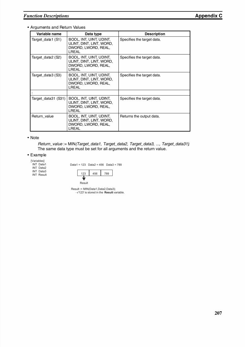
8/11/2019 CX-Programmer V9 Operation Manual FB ST.pdf
http://slidepdf.com/reader/full/cx-programmer-v9-operation-manual-fb-stpdf 233/254
207
Function Descriptions Appendix C
• Arguments and Return Values
• Note
Return_value := MIN(Target_data1, Target_data2, Target_data3, ..., Target_data31) ;The same data type must be set for all arguments and the return value.
• Example
Variable name Data type Description
Target_data1 (S1) BOOL, INT, UINT, UDINT,ULINT, DINT, LINT, WORD,DWORD, LWORD, REAL,LREAL
Specifies the target data.
Target_data2 (S2) BOOL, INT, UINT, UDINT,
ULINT, DINT, LINT, WORD,DWORD, LWORD, REAL,LREAL
Specifies the target data.
Target_data3 (S3) BOOL, INT, UINT, UDINT,ULINT, DINT, LINT, WORD,DWORD, LWORD, REAL,LREAL
Specifies the target data.
:
Target_data31 (S31) BOOL, INT, UINT, UDINT,ULINT, DINT, LINT, WORD,DWORD, LWORD, REAL,LREAL
Specifies the target data.
Return_value BOOL, INT, UINT, UDINT,
ULINT, DINT, LINT, WORD,DWORD, LWORD, REAL,LREAL
Returns the output data.
[Variables]
INT Data1
INT Data2
INT Data3
INT Result
Data1 = 123 Data2 = 456 Data3 = 789
789123 456
Result
Result := MIN(Data1,Data2,Data3);
→'123' is stored in the Result variable.
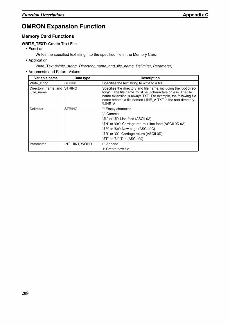
8/11/2019 CX-Programmer V9 Operation Manual FB ST.pdf
http://slidepdf.com/reader/full/cx-programmer-v9-operation-manual-fb-stpdf 234/254
208
Function Descriptions Appendix C
OMRON Expansion Function
Memory Card Functions
WRITE_TEXT: Create Text File
• Function
Writes the specified text sting into the specified file in the Memory Card.
• Application
Write_Text (Write_string, Directory_name_and_file_name, Delimiter, Parameter) ;
• Arguments and Return Values
Variable name Data type Description
Write_string STRING Specifies the text string to write to a file.
Directory_name_and_file_name
STRING Specifies the directory and file name, including the root direc-tory(\). The file name must be 8 characters or less. The filename extension is always TXT. For example, the following filename creates a file named LINE_A.TXT in the root directory: \LINE_A.
Delimiter STRING '': Empty character
',': Comma“$L” or “$l”: Line feed (ASCII 0A)
“$N” or “$n”: Carriage return + line feed (ASCII 0D 0A)
“$P” or “$p”: New page (ASCII 0C)
“$R” or “$r”: Carriage return (ASCII 0D)
“$T” or “$t”: Tab (ASCII 09)
Parameter INT, UINT, WORD 0: Append
1: Create new file
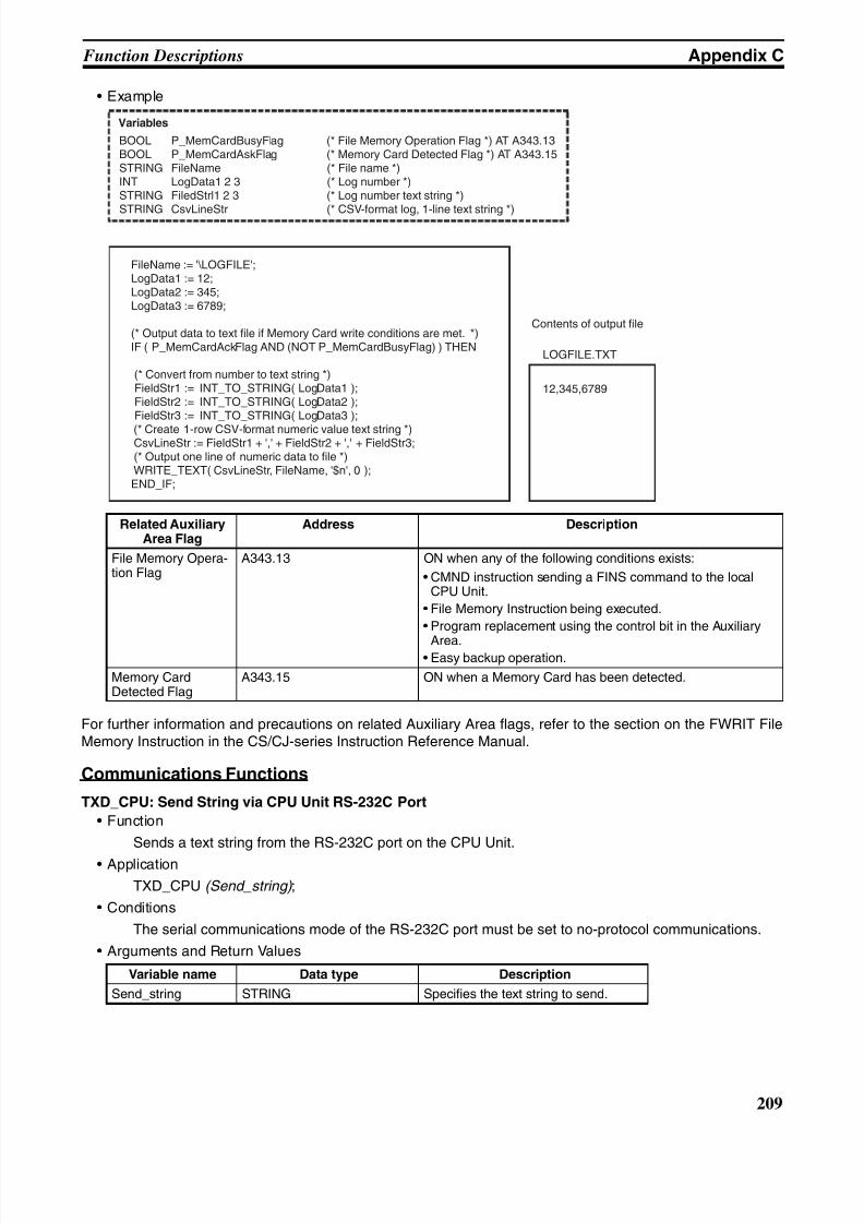
8/11/2019 CX-Programmer V9 Operation Manual FB ST.pdf
http://slidepdf.com/reader/full/cx-programmer-v9-operation-manual-fb-stpdf 235/254
209
Function Descriptions Appendix C
• Example
For further information and precautions on related Auxiliary Area flags, refer to the section on the FWRIT FileMemory Instruction in the CS/CJ-series Instruction Reference Manual.
Communications Functions
TXD_CPU: Send String via CPU Unit RS-232C Port
• Function
Sends a text string from the RS-232C port on the CPU Unit.
• Application
TXD_CPU (Send_string) ;
• Conditions
The serial communications mode of the RS-232C port must be set to no-protocol communications.
• Arguments and Return Values
Related AuxiliaryArea Flag
Address Description
File Memory Opera-tion Flag
A343.13 ON when any of the following conditions exists:
• CMND instruction sending a FINS command to the localCPU Unit.
• File Memory Instruction being executed.
• Program replacement using the control bit in the Auxiliary
Area.• Easy backup operation.
Memory CardDetected Flag
A343.15 ON when a Memory Card has been detected.
Variable name Data type Description
Send_string STRING Specifies the text string to send.
Variables
BOOL P_MemCardBusyFlag (* File Memory Operation Flag *) AT A343.13BOOL P_MemCardAskFlag (* Memory Card Detected Flag *) AT A343.15STRING FileName (* File name *)INT LogData1 2 3 (* Log number *)STRING FiledStrl1 2 3 (* Log number text string *)
STRING CsvLineStr (* CSV-format log, 1-line text string *)
FileName := '\LOGFILE';LogData1 := 12;LogData2 := 345;LogData3 := 6789;
(* Output data to text file if Memory Card write conditions are met. *)IF ( P_MemCardAckFlag AND (NOT P_MemCardBusyFlag) ) THEN
(* Convert from number to text string *) FieldStr1 := INT_TO_STRING( LogData1 ); FieldStr2 := INT_TO_STRING( LogData2 ); FieldStr3 := INT_TO_STRING( LogData3 );
(* Create 1-row CSV-format numeric value text string *) CsvLineStr := FieldStr1 + ',' + FieldStr2 + ',' + FieldStr3; (* Output one line of numeric data to file *) WRITE_TEXT( CsvLineStr, FileName, '$n', 0 );END_IF;
12,345,6789
LOGFILE.TXT
Contents of output file
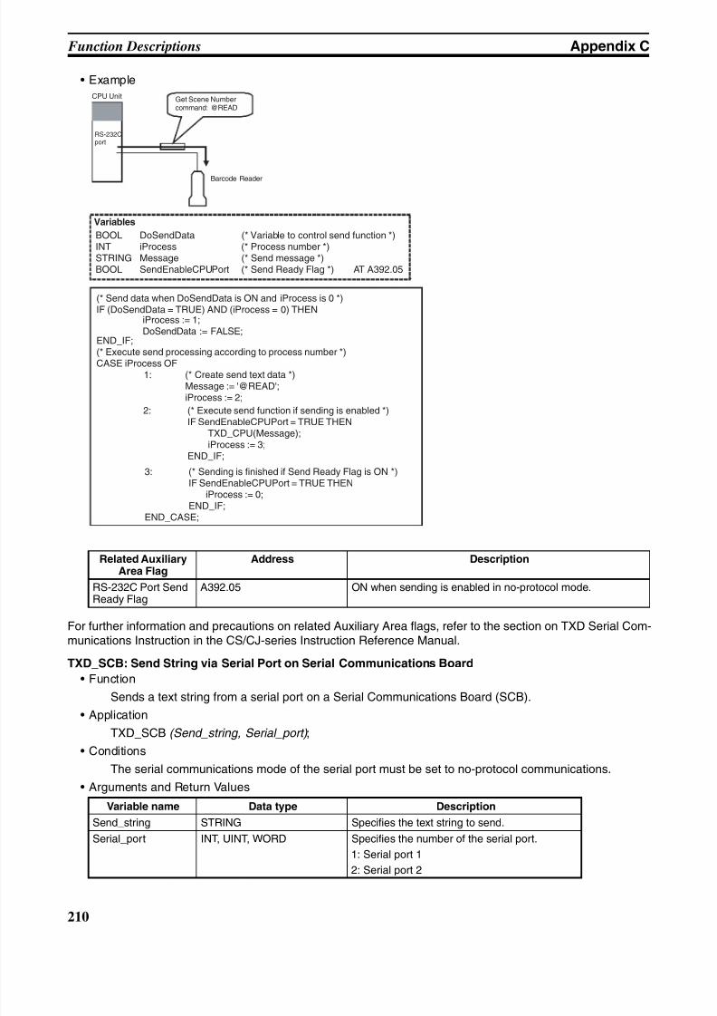
8/11/2019 CX-Programmer V9 Operation Manual FB ST.pdf
http://slidepdf.com/reader/full/cx-programmer-v9-operation-manual-fb-stpdf 236/254
210
Function Descriptions Appendix C
• Example
For further information and precautions on related Auxiliary Area flags, refer to the section on TXD Serial Com-munications Instruction in the CS/CJ-series Instruction Reference Manual.
TXD_SCB: Send String via Serial Port on Serial Communications Board
• Function
Sends a text string from a serial port on a Serial Communications Board (SCB).
• Application
TXD_SCB (Send_string, Serial_port) ;
• Conditions
The serial communications mode of the serial port must be set to no-protocol communications.
• Arguments and Return Values
Related AuxiliaryArea Flag
Address Description
RS-232C Port SendReady Flag
A392.05 ON when sending is enabled in no-protocol mode.
Variable name Data type Description
Send_string STRING Specifies the text string to send.
Serial_port INT, UINT, WORD Specifies the number of the serial port.
1: Serial port 1
2: Serial port 2
Variables
BOOL DoSendData (* Variable to control send function *)INT iProcess (* Process number *)STRING Message (* Send message *)BOOL SendEnableCPUPort (* Send Ready Flag *) AT A392.05
2: (* Execute send function if sending is enabled *)IF SendEnableCPUPort = TRUE THEN
TXD_CPU(Message);iProcess := 3;
END_IF;
(* Send data when DoSendData is ON and iProcess is 0 *)IF (DoSendData = TRUE) AND (iProcess = 0) THEN
END_IF;
(* Execute send processing according to process number *)CASE iProcess OF
iProcess := 1;DoSendData := FALSE;
1: (* Create send text data *)Message := '@READ';iProcess := 2;
CPU Unit
Barcode Reader
3: (* Sending is finished if Send Ready Flag is ON *)IF SendEnableCPUPort = TRUE THEN
iProcess := 0;END_IF;
END_CASE;
Get Scene Numbercommand: @READ
RS-232Cport
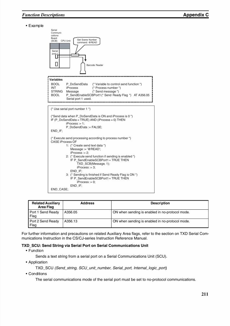
8/11/2019 CX-Programmer V9 Operation Manual FB ST.pdf
http://slidepdf.com/reader/full/cx-programmer-v9-operation-manual-fb-stpdf 237/254
211
Function Descriptions Appendix C
• Example
For further information and precautions on related Auxiliary Area flags, refer to the section on TXD Serial Com-munications Instruction in the CS/CJ-series Instruction Reference Manual.
TXD_SCU: Send String via Serial Port on Serial Communications Unit
• Function
Sends a text string from a serial port on a Serial Communications Unit (SCU).
• Application
TXD_SCU (Send_string, SCU_unit_number, Serial_port, Internal_logic_port) ;
• Conditions
The serial communications mode of the serial port must be set to no-protocol communications.
Related AuxiliaryArea Flag
Address Description
Port 1 Send ReadyFlag
A356.05 ON when sending is enabled in no-protocol mode.
Port 2 Send ReadyFlag
A356.13 ON when sending is enabled in no-protocol mode.
Variables
BOOL P_DoSendData (* Variable to control send function *)INT iProcess (* Process number *)STRING Message (* Send message *)BOOL P_SendEnableSCBPort1 (* Send Ready Flag *) AT A356.05
Serial port 1 used.
(* Use serial port number 1 *)
(*Send data when P_DoSendData is ON and iProcess is 0 *)IF (P_DoSendData = TRUE) AND (iProcess = 0) THEN
iProcess := 1; P_DoSendData := FALSE;END_IF;
(* Execute send processing according to process number *)CASE iProcess OF 1: (* Create send text data *)
Message := '@READ'; iProcess := 2; 2: (* Execute send function if sending is enabled *) IF P_SendEnableSCBPort1 = TRUE THEN TXD_SCB(Message, 1); iProcess := 3;
END_IF; 3: (* Sending is finished if Send Ready Flag is ON *) IF P_SendEnableSCBPort1 = TRUE THEN iProcess := 0; END_IF;END_CASE;
CPU Unit
Barcode Reader
SerialCommuni-cationsBoard(SCB) Get Scene Number
command: @READ
Serialport 1
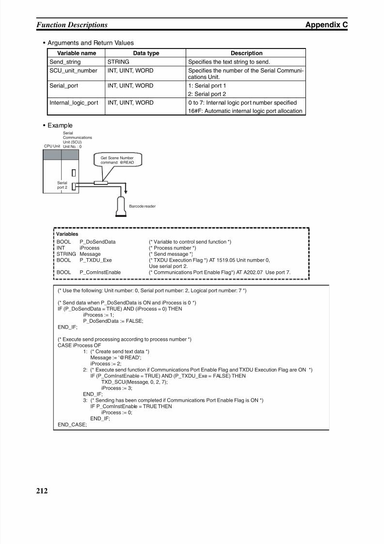
8/11/2019 CX-Programmer V9 Operation Manual FB ST.pdf
http://slidepdf.com/reader/full/cx-programmer-v9-operation-manual-fb-stpdf 238/254
212
Function Descriptions Appendix C
• Arguments and Return Values
• Example
Variable name Data type Description
Send_string STRING Specifies the text string to send.
SCU_unit_number INT, UINT, WORD Specifies the number of the Serial Communi-cations Unit.
Serial_port INT, UINT, WORD 1: Serial port 1
2: Serial port 2Internal_logic_port INT, UINT, WORD 0 to 7: Internal logic port number specified
16#F: Automatic internal logic port allocation
CPU Unit
Barcode reader
Get Scene NumberCommand: @READ
SerialCommunicationsUnit (SCU)Unit No. : 0
Serialport 2
Get Scene Numbercommand: @READ
Variables
BOOL P_DoSendData (* Variable to control send function *)INT iProcess (* Process number *)STRING Message (* Send message *)BOOL P_TXDU_Exe (* TXDU Execution Flag *) AT 1519.05 Unit number 0, Use serial port 2.BOOL P_ComInstEnable (* Communications Port Enable Flag*) AT A202.07 Use port 7.
(* Use the following: Unit number: 0, Serial port number: 2, Logical port number: 7 *)
(* Send data when P_DoSendData is ON and iProcess is 0 *)IF (P_DoSendData = TRUE) AND (iProcess = 0) THEN
iProcess := 1; P_DoSendData := FALSE;END_IF;
(* Execute send processing according to process number *)CASE iProcess OF 1: (* Create send text data *) Message := '@READ'; iProcess := 2; 2: (* Execute send function if Communications Port Enable Flag and TXDU Execution Flag are ON *)
IF (P_ComInstEnable = TRUE) AND (P_TXDU_Exe = FALSE) THEN
TXD_SCU(Message, 0, 2, 7); iProcess := 3; END_IF; 3: (* Sending has been completed if Communications Port Enable Flag is ON *) IF P_ComInstEnable = TRUE THEN iProcess := 0; END_IF;END_CASE;
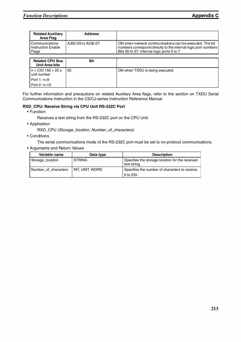
8/11/2019 CX-Programmer V9 Operation Manual FB ST.pdf
http://slidepdf.com/reader/full/cx-programmer-v9-operation-manual-fb-stpdf 239/254
213
Function Descriptions Appendix C
For further information and precautions on related Auxiliary Area flags, refer to the section on TXDU SerialCommunications Instruction in the CS/CJ-series Instruction Reference Manual.
RXD_CPU: Receive String via CPU Unit RS-232C Port
• Function
Receives a text string from the RS-232C port on the CPU Unit.• Application
RXD_CPU (Storage_location, Number_of_characters)
• Conditions
The serial communications mode of the RS-232C port must be set to no-protocol communications.
• Arguments and Return Values
Related AuxiliaryArea Flag
Address
CommunicationsInstruction EnableFlags
A202.00 to A202.07 ON when network communications can be executed. The bitnumbers correspond directly to the internal logic port numbersBits 00 to 07: Internal logic ports 0 to 7
Related CPU BusUnit Area bits
Bit
n = CIO 150 + 25 xunit number
Port 1: n+9
Port 2: n+19
05 ON when TXDU is being executed.
Variable name Data type Description
Storage_location STRING Specifies the storage location for the receivedtext string.
Number_of_characters INT, UINT, WORD Specifies the number of characters to receive.
0 to 255
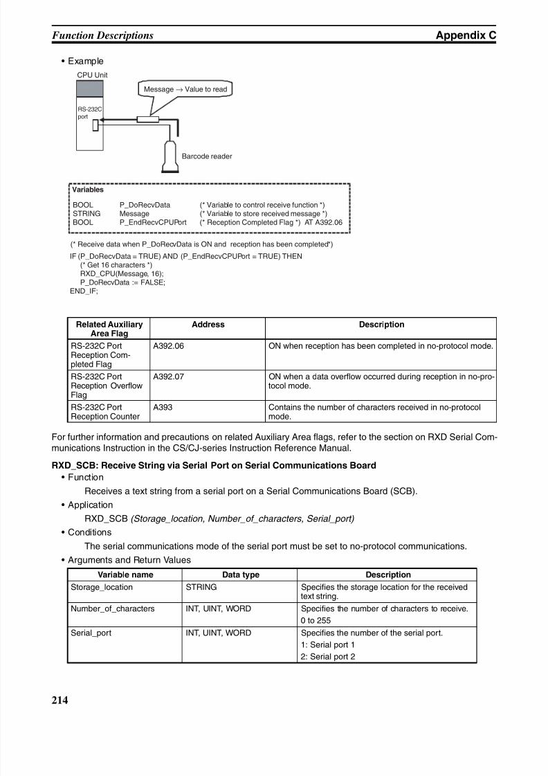
8/11/2019 CX-Programmer V9 Operation Manual FB ST.pdf
http://slidepdf.com/reader/full/cx-programmer-v9-operation-manual-fb-stpdf 240/254
214
Function Descriptions Appendix C
• Example
For further information and precautions on related Auxiliary Area flags, refer to the section on RXD Serial Com-munications Instruction in the CS/CJ-series Instruction Reference Manual.
RXD_SCB: Receive String via Serial Port on Serial Communications Board
• Function
Receives a text string from a serial port on a Serial Communications Board (SCB).
• Application
RXD_SCB (Storage_location, Number_of_characters, Serial_port)
• Conditions
The serial communications mode of the serial port must be set to no-protocol communications.
• Arguments and Return Values
Related AuxiliaryArea Flag
Address Description
RS-232C PortReception Com-pleted Flag
A392.06 ON when reception has been completed in no-protocol mode.
RS-232C PortReception OverflowFlag
A392.07 ON when a data overflow occurred during reception in no-pro-tocol mode.
RS-232C PortReception Counter
A393 Contains the number of characters received in no-protocolmode.
Variable name Data type Description
Storage_location STRING Specifies the storage location for the receivedtext string.
Number_of_characters INT, UINT, WORD Specifies the number of characters to receive.
0 to 255
Serial_port INT, UINT, WORD Specifies the number of the serial port.
1: Serial port 1
2: Serial port 2
Variables
BOOL P_DoRecvData (* Variable to control receive function *)STRING Message (* Variable to store received message *)BOOL P_EndRecvCPUPort (* Reception Completed Flag *) AT A392.06
(* Receive data when P_DoRecvData is ON and reception has been completed*)
IF (P_DoRecvData = TRUE) AND (P_EndRecvCPUPort = TRUE) THEN(* Get 16 characters *)
RXD_CPU(Message, 16);P_DoRecvData := FALSE;
END_IF;
Barcode reader
CPU Unit
RS-232Cport
Message → Value to read
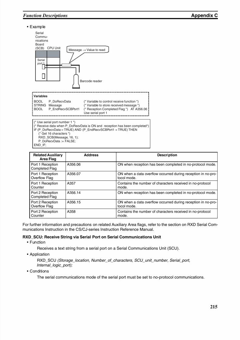
8/11/2019 CX-Programmer V9 Operation Manual FB ST.pdf
http://slidepdf.com/reader/full/cx-programmer-v9-operation-manual-fb-stpdf 241/254
215
Function Descriptions Appendix C
• Example
For further information and precautions on related Auxiliary Area flags, refer to the section on RXD Serial Com-munications Instruction in the CS/CJ-series Instruction Reference Manual.
RXD_SCU: Receive String via Serial Port on Serial Communications Unit• Function
Receives a text string from a serial port on a Serial Communications Unit (SCU).
• Application
RXD_SCU (Storage_location, Number_of_characters, SCU_unit_number, Serial_port,Internal_logic_port);
• Conditions
The serial communications mode of the serial port must be set to no-protocol communications.
Related AuxiliaryArea Flag
Address Description
Port 1 ReceptionCompleted Flag
A356.06 ON when reception has been completed in no-protocol mode.
Port 1 Reception
Overflow Flag
A356.07 ON when a data overflow occurred during reception in no-pro-
tocol mode.Port 1 ReceptionCounter
A357 Contains the number of characters received in no-protocolmode.
Port 2 ReceptionCompleted Flag
A356.14 ON when reception has been completed in no-protocol mode.
Port 2 ReceptionOverflow Flag
A356.15 ON when a data overflow occurred during reception in no-pro-tocol mode.
Port 2 ReceptionCounter
A358 Contains the number of characters received in no-protocolmode.
Variables
BOOL P_DoRecvData (* Variable to control receive function *)STRING Message (* Variable to store received message *)BOOL P_EndRecvSCBPort1 (* Reception Completed Flag *) AT A356.06
Use serial port 1
(* Use serial port number 1 *)(* Receive data when P_DoRecvData is ON and reception has been completed*)IF (P_DoRecvData = TRUE) AND (P_EndRecvSCBPort1 = TRUE) THEN (* Get 16 characters *) RXD_SCB(Message, 16, 1);
P_DoRecvData := FALSE;END_IF;
Barcode reader
CPU Unit
SerialCommu-nicationsBoard(SCB)
Serialport 1
Message → Value to read
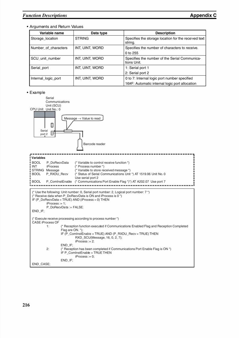
8/11/2019 CX-Programmer V9 Operation Manual FB ST.pdf
http://slidepdf.com/reader/full/cx-programmer-v9-operation-manual-fb-stpdf 242/254
216
Function Descriptions Appendix C
• Arguments and Return Values
• Example
Variable name Data type Description
Storage_location STRING Specifies the storage location for the received textstring.
Number_of_characters INT, UINT, WORD Specifies the number of characters to receive.
0 to 255
SCU_unit_number INT, UINT, WORD Specifies the number of the Serial Communica-tions Unit.
Serial_port INT, UINT, WORD 1: Serial port 1
2: Serial port 2
Internal_logic_port INT, UINT, WORD 0 to 7: Internal logic port number specified
16#F: Automatic internal logic port allocation
Barcode reader
CPU Unit
SerialCommunicationsUnit (SCU)Unit No.: 0
Message → Value to read
Serialport 2
Variables
BOOL P_DoRecvData (* Variable to control receive function *)INT iProcess (* Process number *)STRING Message (* Variable to store received message *)BOOL P_RXDU_Recv (* Status of Serial Communications Unit *) AT 1519.06 Unit No. 0
Use serial port 2BOOL P_ComInstEnable (* Communications Port Enable Flag *)*) AT A202.07 Use port 7
(* Use the following: Unit number: 0, Serial port number: 2, Logical port number: 7 *)(* Receive data when P_DoRecvData is ON and iProcess is 0 *)IF (P_DoRecvData = TRUE) AND (iProcess = 0) THEN iProcess := 1; P_DoRecvData := FALSE;END_IF;
(* Execute receive processing according to process number *)CASE iProcess OF 1: (* Reception function executed if Communications Enabled Flag and Reception Completed
Flag are ON. *); IF (P_ComInstEnable = TRUE) AND (P_RXDU_Recv = TRUE) THEN
RXD_SCU(Message, 16, 0, 2, 7); iProcess := 2; END_IF; 2: (* Reception has been completed if Communications Port Enable Flag is ON *) IF P_ComInstEnable = TRUE THEN iProcess := 0; END_IF;END_CASE;
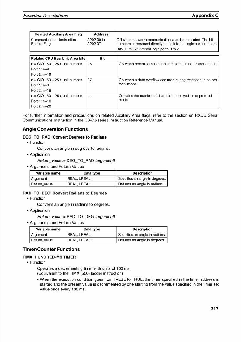
8/11/2019 CX-Programmer V9 Operation Manual FB ST.pdf
http://slidepdf.com/reader/full/cx-programmer-v9-operation-manual-fb-stpdf 243/254
217
Function Descriptions Appendix C
For further information and precautions on related Auxiliary Area flags, refer to the section on RXDU Serial
Communications Instruction in the CS/CJ-series Instruction Reference Manual.
Angle Conversion Functions
DEG_TO_RAD: Convert Degrees to Radians
• Function
Converts an angle in degrees to radians.
• Application
Return_value := DEG_TO_RAD (argument)
• Arguments and Return Values
RAD_TO_DEG: Convert Radians to Degrees
• Function
Converts an angle in radians to degrees.
• Application
Return_value := RAD_TO_DEG (argument)
• Arguments and Return Values
Timer/Counter Functions
TIMX: HUNDRED-MS TIMER
• Function
Operates a decrementing timer with units of 100 ms.(Equivalent to the TIMX (550) ladder instruction)
• When the execution condition goes from FALSE to TRUE, the timer specified in the timer address isstarted and the present value is decremented by one starting from the value specified in the timer setvalue once every 100 ms.
Related Auxiliary Area Flag Address
Communications InstructionEnable Flag
A202.00 toA202.07
ON when network communications can be executed. The bitnumbers correspond directly to the internal logic port numbers
Bits 00 to 07: Internal logic ports 0 to 7
Related CPU Bus Unit Area bits Bitn = CIO 150 + 25 x unit number
Port 1: n+9
Port 2: n+19
06 ON when reception has been completed in no-protocol mode.
n = CIO 150 + 25 x unit number
Port 1: n+9
Port 2: n+19
07 ON when a data overflow occurred during reception in no-pro-tocol mode.
n = CIO 150 + 25 x unit number
Port 1: n+10
Port 2: n+20
--- Contains the number of characters received in no-protocolmode.
Variable name Data type Description
Argument REAL, LREAL Specifies an angle in degrees.Return_value REAL, LREAL Returns an angle in radians.
Variable name Data type Description
Argument REAL, LREAL Specifies an angle in radians.
Return_value REAL, LREAL Returns an angle in degrees.
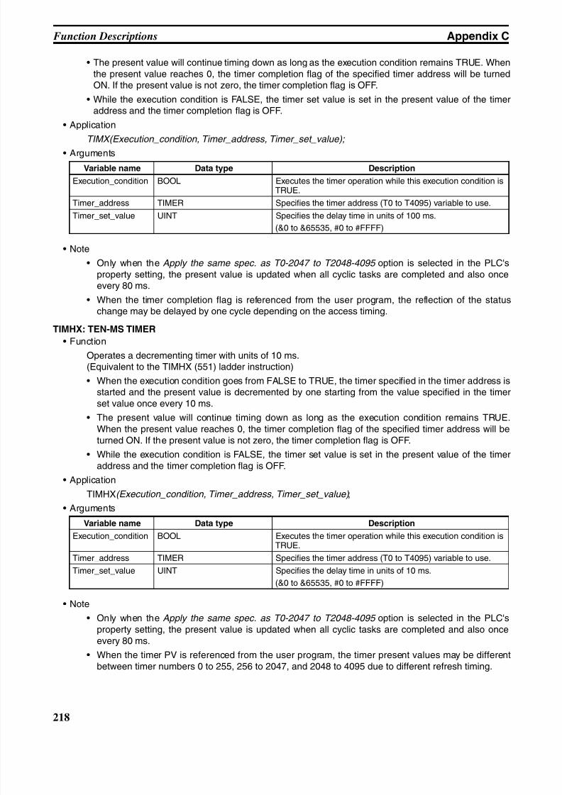
8/11/2019 CX-Programmer V9 Operation Manual FB ST.pdf
http://slidepdf.com/reader/full/cx-programmer-v9-operation-manual-fb-stpdf 244/254
218
Function Descriptions Appendix C
• The present value will continue timing down as long as the execution condition remains TRUE. Whenthe present value reaches 0, the timer completion flag of the specified timer address will be turnedON. If the present value is not zero, the timer completion flag is OFF.
• While the execution condition is FALSE, the timer set value is set in the present value of the timeraddress and the timer completion flag is OFF.
• Application
TIMX(Execution_condition, Timer_address, Timer_set_value); • Arguments
• Note
• Only when the Apply the same spec. as T0-2047 to T2048-4095 option is selected in the PLC's
property setting, the present value is updated when all cyclic tasks are completed and also onceevery 80 ms.
• When the timer completion flag is referenced from the user program, the reflection of the statuschange may be delayed by one cycle depending on the access timing.
TIMHX: TEN-MS TIMER
• Function
Operates a decrementing timer with units of 10 ms.(Equivalent to the TIMHX (551) ladder instruction)
• When the execution condition goes from FALSE to TRUE, the timer specified in the timer address isstarted and the present value is decremented by one starting from the value specified in the timerset value once every 10 ms.
• The present value will continue timing down as long as the execution condition remains TRUE.When the present value reaches 0, the timer completion flag of the specified timer address will beturned ON. If the present value is not zero, the timer completion flag is OFF.
• While the execution condition is FALSE, the timer set value is set in the present value of the timeraddress and the timer completion flag is OFF.
• Application
TIMHX(Execution_condition, Timer_address, Timer_set_value) ;
• Arguments
• Note
• Only when the Apply the same spec. as T0-2047 to T2048-4095 option is selected in the PLC'sproperty setting, the present value is updated when all cyclic tasks are completed and also onceevery 80 ms.
• When the timer PV is referenced from the user program, the timer present values may be differentbetween timer numbers 0 to 255, 256 to 2047, and 2048 to 4095 due to different refresh timing.
Variable name Data type Description
Execution_condition BOOL Executes the timer operation while this execution condition isTRUE.
Timer_address TIMER Specifies the timer address (T0 to T4095) variable to use.
Timer_set_value UINT Specifies the delay time in units of 100 ms.
(&0 to &65535, #0 to #FFFF)
Variable name Data type Description
Execution_condition BOOL Executes the timer operation while this execution condition isTRUE.
Timer_address TIMER Specifies the timer address (T0 to T4095) variable to use.Timer_set_value UINT Specifies the delay time in units of 10 ms.
(&0 to &65535, #0 to #FFFF)
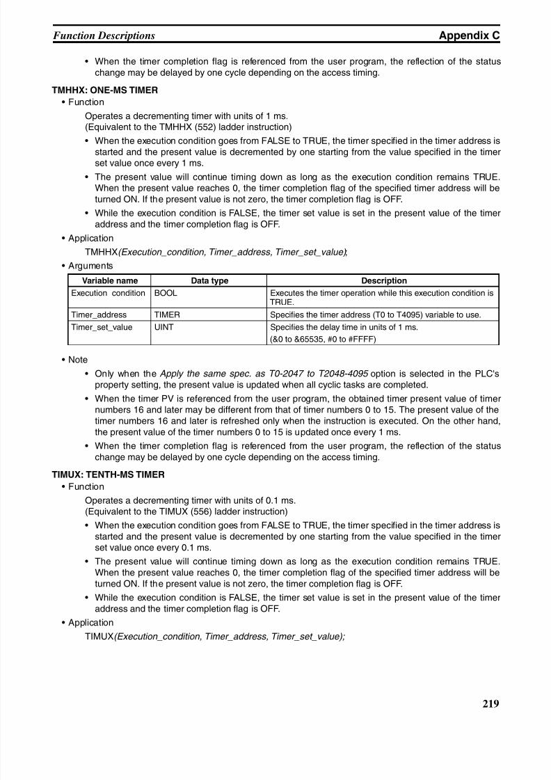
8/11/2019 CX-Programmer V9 Operation Manual FB ST.pdf
http://slidepdf.com/reader/full/cx-programmer-v9-operation-manual-fb-stpdf 245/254
219
Function Descriptions Appendix C
• When the timer completion flag is referenced from the user program, the reflection of the statuschange may be delayed by one cycle depending on the access timing.
TMHHX: ONE-MS TIMER
• Function
Operates a decrementing timer with units of 1 ms.(Equivalent to the TMHHX (552) ladder instruction)
• When the execution condition goes from FALSE to TRUE, the timer specified in the timer address isstarted and the present value is decremented by one starting from the value specified in the timerset value once every 1 ms.
• The present value will continue timing down as long as the execution condition remains TRUE.When the present value reaches 0, the timer completion flag of the specified timer address will beturned ON. If the present value is not zero, the timer completion flag is OFF.
• While the execution condition is FALSE, the timer set value is set in the present value of the timeraddress and the timer completion flag is OFF.
• Application
TMHHX(Execution_condition, Timer_address, Timer_set_value) ;
• Arguments
• Note
• Only when the Apply the same spec. as T0-2047 to T2048-4095 option is selected in the PLC'sproperty setting, the present value is updated when all cyclic tasks are completed.
• When the timer PV is referenced from the user program, the obtained timer present value of timer
numbers 16 and later may be different from that of timer numbers 0 to 15. The present value of thetimer numbers 16 and later is refreshed only when the instruction is executed. On the other hand,the present value of the timer numbers 0 to 15 is updated once every 1 ms.
• When the timer completion flag is referenced from the user program, the reflection of the statuschange may be delayed by one cycle depending on the access timing.
TIMUX: TENTH-MS TIMER
• Function
Operates a decrementing timer with units of 0.1 ms.(Equivalent to the TIMUX (556) ladder instruction)
• When the execution condition goes from FALSE to TRUE, the timer specified in the timer address isstarted and the present value is decremented by one starting from the value specified in the timer
set value once every 0.1 ms.• The present value will continue timing down as long as the execution condition remains TRUE.
When the present value reaches 0, the timer completion flag of the specified timer address will beturned ON. If the present value is not zero, the timer completion flag is OFF.
• While the execution condition is FALSE, the timer set value is set in the present value of the timeraddress and the timer completion flag is OFF.
• Application
TIMUX(Execution_condition, Timer_address, Timer_set_value);
Variable name Data type Description
Execution_condition BOOL Executes the timer operation while this execution condition isTRUE.
Timer_address TIMER Specifies the timer address (T0 to T4095) variable to use.
Timer_set_value UINT Specifies the delay time in units of 1 ms.
(&0 to &65535, #0 to #FFFF)
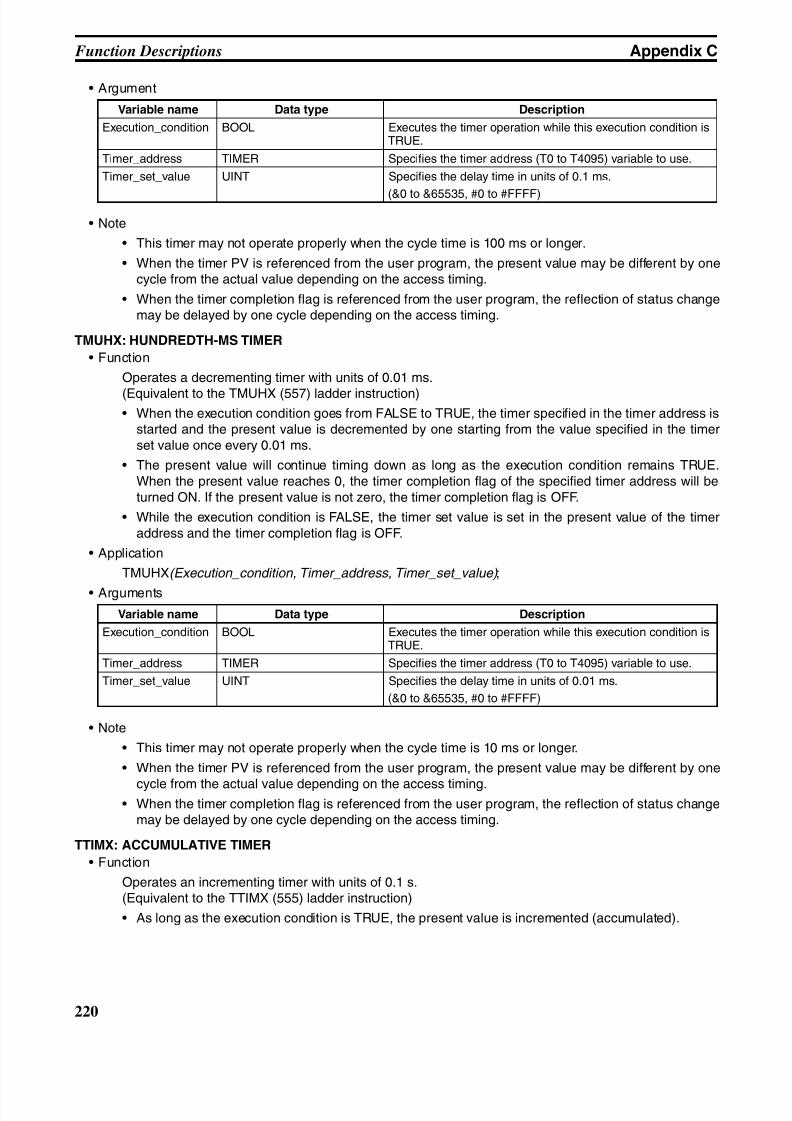
8/11/2019 CX-Programmer V9 Operation Manual FB ST.pdf
http://slidepdf.com/reader/full/cx-programmer-v9-operation-manual-fb-stpdf 246/254
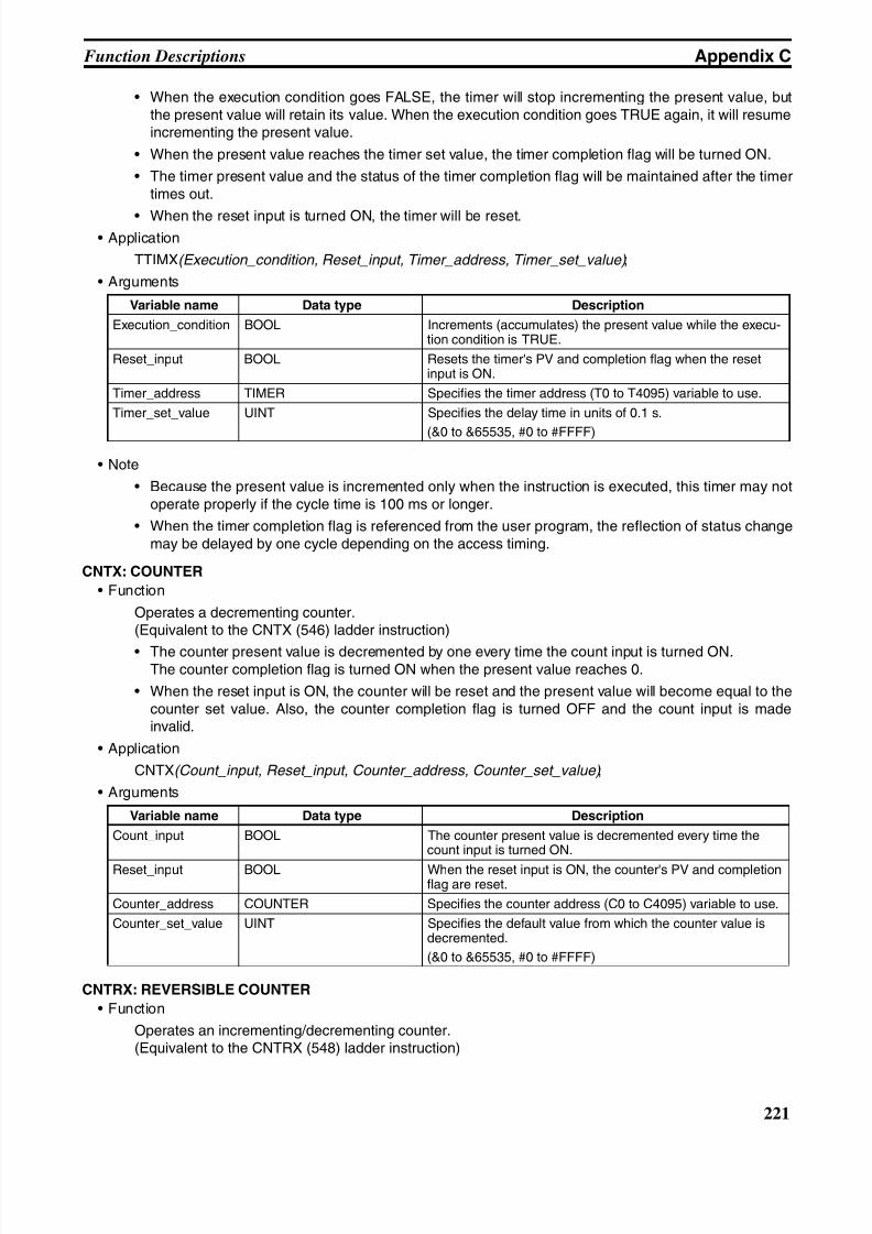
8/11/2019 CX-Programmer V9 Operation Manual FB ST.pdf
http://slidepdf.com/reader/full/cx-programmer-v9-operation-manual-fb-stpdf 247/254
221
Function Descriptions Appendix C
• When the execution condition goes FALSE, the timer will stop incrementing the present value, butthe present value will retain its value. When the execution condition goes TRUE again, it will resumeincrementing the present value.
• When the present value reaches the timer set value, the timer completion flag will be turned ON.
• The timer present value and the status of the timer completion flag will be maintained after the timertimes out.
• When the reset input is turned ON, the timer will be reset.• Application
TTIMX(Execution_condition, Reset_input, Timer_address, Timer_set_value) ;
• Arguments
• Note
• Because the present value is incremented only when the instruction is executed, this timer may notoperate properly if the cycle time is 100 ms or longer.
• When the timer completion flag is referenced from the user program, the reflection of status changemay be delayed by one cycle depending on the access timing.
CNTX: COUNTER
• Function
Operates a decrementing counter.(Equivalent to the CNTX (546) ladder instruction)
• The counter present value is decremented by one every time the count input is turned ON.The counter completion flag is turned ON when the present value reaches 0.
• When the reset input is ON, the counter will be reset and the present value will become equal to thecounter set value. Also, the counter completion flag is turned OFF and the count input is madeinvalid.
• Application
CNTX(Count_input, Reset_input, Counter_address, Counter_set_value) ;
• Arguments
CNTRX: REVERSIBLE COUNTER
• Function
Operates an incrementing/decrementing counter.(Equivalent to the CNTRX (548) ladder instruction)
Variable name Data type Description
Execution_condition BOOL Increments (accumulates) the present value while the execu-tion condition is TRUE.
Reset_input BOOL Resets the timer's PV and completion flag when the resetinput is ON.
Timer_address TIMER Specifies the timer address (T0 to T4095) variable to use.
Timer_set_value UINT Specifies the delay time in units of 0.1 s.
(&0 to &65535, #0 to #FFFF)
Variable name Data type Description
Count_input BOOL The counter present value is decremented every time thecount input is turned ON.
Reset_input BOOL When the reset input is ON, the counter's PV and completionflag are reset.
Counter_address COUNTER Specifies the counter address (C0 to C4095) variable to use.
Counter_set_value UINT Specifies the default value from which the counter value isdecremented.
(&0 to &65535, #0 to #FFFF)
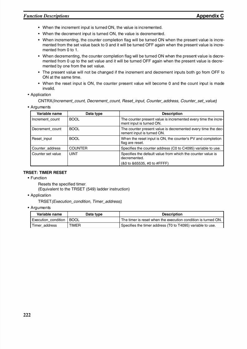
8/11/2019 CX-Programmer V9 Operation Manual FB ST.pdf
http://slidepdf.com/reader/full/cx-programmer-v9-operation-manual-fb-stpdf 248/254
222
Function Descriptions Appendix C
• When the increment input is turned ON, the value is incremented.
• When the decrement input is turned ON, the value is decremented.
• When incrementing, the counter completion flag will be turned ON when the present value is incre-mented from the set value back to 0 and it will be turned OFF again when the present value is incre-mented from 0 to 1.
• When decrementing, the counter completion flag will be turned ON when the present value is decre-
mented from 0 up to the set value and it will be turned OFF again when the present value is decre-mented by one from the set value.
• The present value will not be changed if the increment and decrement inputs both go from OFF toON at the same time.
• When the reset input is ON, the counter present value will become 0 and the count input is madeinvalid.
• Application
CNTRX(Increment_count, Decrement_count, Reset_input, Counter_address, Counter_set_value) ;
• Arguments
TRSET: TIMER RESET
• Function
Resets the specified timer.(Equivalent to the TRSET (549) ladder instruction)
• Application
TRSET(Execution_condition, Timer_address) ;
• Arguments
Variable name Data type Description
Increment_count BOOL The counter present value is incremented every time the incre-
ment input is turned ON.
Decrement_count BOOL The counter present value is decremented every time the dec-rement input is turned ON.
Reset_input BOOL When the reset input is ON, the counter's PV and completionflag are reset.
Counter_address COUNTER Specifies the counter address (C0 to C4095) variable to use.
Counter set value UINT Specifies the default value from which the counter value isdecremented.
(&0 to &65535, #0 to #FFFF)
Variable name Data type Description
Execution_condition BOOL The timer is reset when the execution condition is turned ON.
Timer_address TIMER Specifies the timer address (T0 to T4095) variable to use.
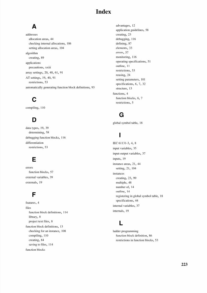
8/11/2019 CX-Programmer V9 Operation Manual FB ST.pdf
http://slidepdf.com/reader/full/cx-programmer-v9-operation-manual-fb-stpdf 249/254
223
Index
Aaddresses
allocation areas, 44
checking internal allocations, 106
setting allocation areas, 104
algorithm
creating, 89
applications
precautions, xxiii
array settings, 20, 40, 61, 91
AT settings, 19, 40, 91
restrictions, 53
automatically generating function block definitions, 93
Ccompiling, 110
Ddata types, 19, 39
determining, 58
debugging function blocks, 116
differentiation
restrictions, 53
Eerrors
function blocks, 57
external variables, 39
externals, 19
Ffeatures, 4
files
function block definitions, 114
library, 8
project text files, 8
function block definitions, 13
checking for an instance, 108
compiling, 110
creating, 84
saving to files, 114
function blocks
advantages, 12
application guidelines, 58
creating, 23
debugging, 116
defining, 87
elements, 33
errors, 57
monitoring, 116
operating specifications, 51
outline, 11
restrictions, 53
reusing, 24
setting parameters, 101
specifications, 6, 7, 32
structure, 13
functions, 4
function blocks, 6, 7
restrictions, 5
Gglobal symbol table, 18
IIEC 61131-3, 4, 8
input variables, 35
input-output variables, 37inputs, 19
instance areas, 21, 44
setting, 21, 104
instances
creating, 23, 99
multiple, 48
number of , 14
outline, 14
registering in global symbol table, 18
specifications, 44
internal variables, 37
internals, 19
Lladder programming
function block definition, 86
restrictions in function blocks, 53
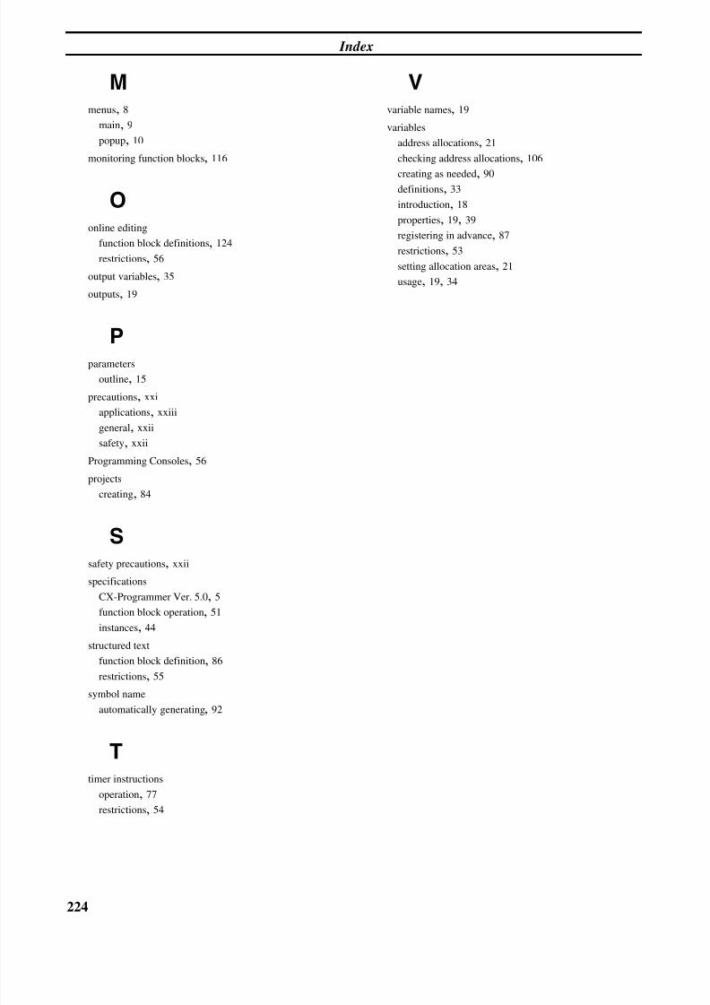
8/11/2019 CX-Programmer V9 Operation Manual FB ST.pdf
http://slidepdf.com/reader/full/cx-programmer-v9-operation-manual-fb-stpdf 250/254
224
Index
Mmenus, 8
main, 9
popup, 10
monitoring function blocks, 116
Oonline editing
function block definitions, 124
restrictions, 56
output variables, 35
outputs, 19
Pparameters
outline, 15
precautions, xxi
applications, xxiii
general, xxii
safety, xxii
Programming Consoles, 56
projects
creating, 84
Ssafety precautions, xxii
specifications
CX-Programmer Ver. 5.0, 5
function block operation, 51
instances, 44
structured text
function block definition, 86
restrictions, 55
symbol name
automatically generating, 92
Ttimer instructions
operation, 77
restrictions, 54
Vvariable names, 19
variables
address allocations, 21
checking address allocations, 106
creating as needed, 90definitions, 33
introduction, 18
properties, 19, 39
registering in advance, 87
restrictions, 53
setting allocation areas, 21
usage, 19, 34
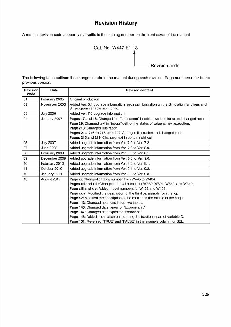
8/11/2019 CX-Programmer V9 Operation Manual FB ST.pdf
http://slidepdf.com/reader/full/cx-programmer-v9-operation-manual-fb-stpdf 251/254

8/11/2019 CX-Programmer V9 Operation Manual FB ST.pdf
http://slidepdf.com/reader/full/cx-programmer-v9-operation-manual-fb-stpdf 252/254
226
Revision History

8/11/2019 CX-Programmer V9 Operation Manual FB ST.pdf
http://slidepdf.com/reader/full/cx-programmer-v9-operation-manual-fb-stpdf 253/254
8/11/2019 CX-Programmer V9 Operation Manual FB ST.pdf
http://slidepdf.com/reader/full/cx-programmer-v9-operation-manual-fb-stpdf 254/254