cut charts - vicon
TRANSCRIPT
OPERATION
4-12 HPR260 Auto Gas Instruction Manual5
Cut charts
The following Cut charts show the consumable parts, cutting speeds and the gas and torch settings required for eachprocess.
The numbers shown in the Cut charts are recommended to provide high-quality cuts with minimal dross. Because ofdifferences between installations and material composition, adjustments may be required to obtain desired results.
Bevel cutting
See Appendix C in this manual for cut charts and consumables.
Marking
Any of the consumable sets can also be used for marking. Marking parameters are shown at the bottom of each cutchart. The quality of the markings will vary depending on the cut process, material type, and material thicknesscombination. Marking is not possible for every combination (very thin materials). Poor quality marking or burn-throughmay occur with material less than 1.5 mm (0.060 in or 16 gauge).
Consumables for mirror-image cutting
See the Parts List section in this manual for part numbers.
OPERATION
HPR260 Auto Gas Instruction Manual 4-135
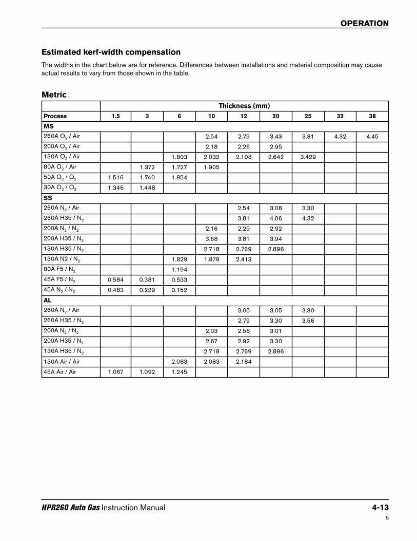
Estimated kerf-width compensation
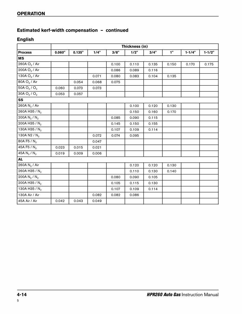
The widths in the chart below are for reference. Differences between installations and material composition may causeactual results to vary from those shown in the table.
Metric
Thickness (mm)
Process 1.5 3 6 10 12 20 25 32 38
MS
260A O2 / Air 2.54 2.79 3.43 3.81 4.32 4.45
200A O2 / Air 2.18 2.26 2.95
130A O2 / Air 1.803 2.032 2.108 2.642 3.429
80A O2 / Air 1.372 1.727 1.905
50A O2 / O2 1.516 1.740 1.854
30A O2 / O2 1.346 1.448
SS
260A N2 / Air 2.54 3.08 3.30
260A H35 / N2 3.81 4.06 4.32
200A N2 / N2 2.16 2.29 2.92
200A H35 / N2 3.68 3.81 3.94
130A H35 / N2 2.718 2.769 2.896
130A N2 / N2 1.829 1.879 2.413
80A F5 / N2 1.194
45A F5 / N2 0.584 0.381 0.533
45A N2 / N2 0.483 0.229 0.152
AL
260A N2 / Air 3.05 3.05 3.30
260A H35 / N2 2.79 3.30 3.56
200A N2 / N2 2.03 2.58 3.01
200A H35 / N2 2.67 2.92 3.30
130A H35 / N2 2.718 2.769 2.896
130A Air / Air 2.083 2.083 2.184
45A Air / Air 1.067 1.092 1.245
OPERATION
4-14 HPR260 Auto Gas Instruction Manual
English
Thickness (in)
Process 0.060" 0.135" 1/4" 3/8" 1/2" 3/4" 1" 1-1/4" 1-1/2"
MS
260A O2 / Air 0.100 0.110 0.135 0.150 0.170 0.175
200A O2 / Air 0.086 0.089 0.116
130A O2 / Air 0.071 0.080 0.083 0.104 0.135
80A O2 / Air 0.054 0.068 0.075
50A O2 / O2 0.060 0.073 0.073
30A O2 / O2 0.053 0.057
SS
260A N2 / Air 0.100 0.120 0.130
260A H35 / N2 0.150 0.160 0.170
200A N2 / N2 0.085 0.090 0.115
200A H35 / N2 0.145 0.150 0.155
130A H35 / N2 0.107 0.109 0.114
130A N2 / N2 0.072 0.074 0.095
80A F5 / N2 0.047
45A F5 / N2 0.023 0.015 0.021
45A N2 / N2 0.019 0.009 0.006
AL
260A N2 / Air 0.120 0.120 0.130
260A H35 / N2 0.110 0.130 0.140
200A N2 / N2 0.080 0.090 0.105
200A H35 / N2 0.105 0.115 0.130
130A H35 / N2 0.107 0.109 0.114
130A Air / Air 0.082 0.082 0.086
45A Air / Air 0.042 0.043 0.049
Estimated kerf-width compensation – continued
5

OPERATION
HPR260 Auto Gas Instruction Manual 4-155
Mild steel
O2 Plasma / O2 Shield
30 A Cutting
220194220173 220192220313 220180220193
*Pierce complete is recommended for these thicknesses
Note: Air must be connected to use this process. It is used as the preflow gas
SelectGases
SetPreflow
SetCutflow
Material
Thickness
ArcVoltage
Torch-to-WorkDistance
CuttingSpeed
Initial PierceHeight
Pierce DelayTime
Plasma Shield Plasma Shield Plasma Shield mm Volts mm mm/m mm factor % seconds
O2 O2 78
17
94
17
0.5 114
1.3
5355
2.3
180
0.1
0.8 115 4225 0.2
1 116 3615
0.31.2 117 2865
1.5 119 2210
35
7
2 120
1.5
1490
2.7
0.42.5 122 1325
75
3* 123 1160 0.5
4* 125 905 0.7
6* 128 665 1.0
Metric
SelectGases
SetPreflow
SetCutflow
Material
Thickness
ArcVoltage
Torch-to-WorkDistance
CuttingSpeed
Initial PierceHeight
Pierce DelayTime
Plasma Shield Plasma Shield Plasma Shield in Volts in ipm in factor % seconds
O2 O2 78
17
94
17
.018114
0.050
215
0.090
180
0.1.024 200
.030 115 170 0.2
.036 116 155
0.3.048 117 110
.060 119 85
35
7
.075 120
0.060
60
0.110
0.4.105 122 50
75
.135* 123 40 0.5
3/16*128
30 0.7
1/4* 25 1.0
English
Select Gases
SetPreflow
SetCutflow
AmperageTorch-to-Work
DistanceMarkingSpeed
ArcVoltage
Amps mm in mm/min ipm Volts
N2 N2 10 10 10 10 15 2.5 0.100 6350 250 105
Marking
Mild steel
O2 Plasma / O2 Shield
30 A Cutting
Flow rates – lpm/scfh
O2 Air
Preflow 0 / 0 43 / 90
Cutflow 25 / 52 0 / 0

OPERATION
4-16 HPR260 Auto Gas Instruction Manual
Mild steel
O2 Plasma / O2 Shield
50 A Cutting
220555220173 220552220313 220553220554
Note: Air must be connected to use this process. It is used as the preflow gas
5
SelectGases
SetPreflow
SetCutflow
Material
Thickness
ArcVoltage
Torch-to-WorkDistance
CuttingSpeed
Initial PierceHeight
Pierce DelayTime
Plasma Shield Plasma Shield Plasma Shield in Volts in ipm in factor % seconds
O2 O2 70 30 81 14
.030110
0.04
270
0.08
200
0.0
.036 210
.048 112 160
.060 114
0.05
125
0.10.075 115 110
.105 118 80 0.1
.135 1200.06
600.12
0.2
3/16 121 50 0.3
1/4 1250.08
350.16 0.5
5/16 130 25
English
Select Gases
SetPreflow
SetCutflow
AmperageTorch-to-Work
DistanceMarkingSpeed
ArcVoltage
Amps mm in mm/min ipm Volts
N2 N2 10 10 10 10 15 2.5 0.100 6350 250 118
Marking
SelectGases
SetPreflow
SetCutflow
Material
Thickness
ArcVoltage
Torch-to-WorkDistance
CuttingSpeed
Initial PierceHeight
Pierce DelayTime
Plasma Shield Plasma Shield Plasma Shield mm Volts mm mm/m mm factor % seconds
O2 O2 70 30 81 14
0.8 110
1.0
6500
2.0
200
0.0
1 111 5000
1.2 112 4150
1.5 114
1.3
3200
2.62 115 2700
2.5 117 2200 0.1
3 119
1.5
1800
3.0
0.2
4 121 1400 0.3
5 122 1200 0.4
6 126
2.0
950
4.0 0.57 128 780
8 130 630
Metric
Flow rates – lpm/scfh
O2 Air
Preflow 0 / 0 43 / 90
Cutflow 25 / 52 0 / 0
OPERATION
HPR260 Auto Gas Instruction Manual 4-174
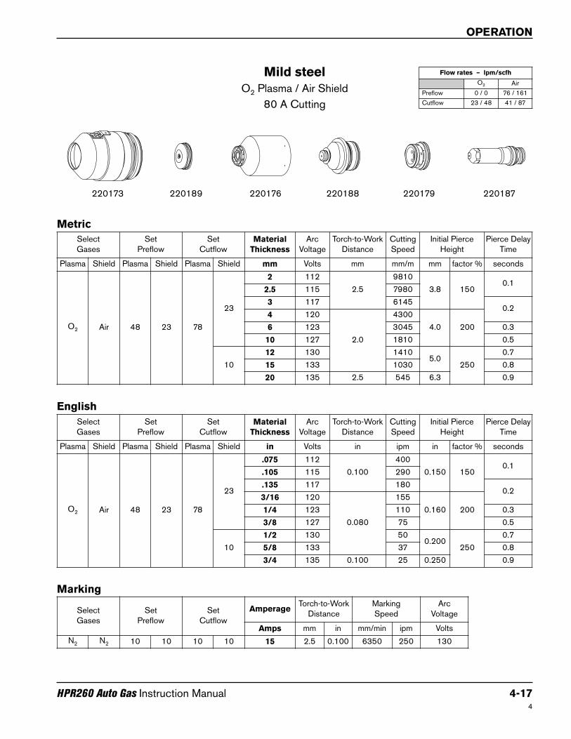
Mild steel
O2 Plasma / Air Shield
80 A Cutting
220189220173 220187220176 220179220188
Metric
English
Select Gases
SetPreflow
SetCutflow
AmperageTorch-to-Work
DistanceMarkingSpeed
ArcVoltage
Amps mm in mm/min ipm Volts
N2 N2 10 10 10 10 15 2.5 0.100 6350 250 130
Marking
SelectGases
SetPreflow
SetCutflow
Material
Thickness
ArcVoltage
Torch-to-WorkDistance
CuttingSpeed
Initial PierceHeight
Pierce DelayTime
Plasma Shield Plasma Shield Plasma Shield mm Volts mm mm/m mm factor % seconds
O2 Air 48 23 78
23
2 112
2.5
9810
3.8 1500.1
2.5 115 7980
3 117 61450.2
4 120
2.0
4300
4.0 2006 123 3045 0.3
10 127 1810 0.5
10
12 130 14105.0
250
0.7
15 133 1030 0.8
20 135 2.5 545 6.3 0.9
SelectGases
SetPreflow
SetCutflow
Material
Thickness
ArcVoltage
Torch-to-WorkDistance
CuttingSpeed
Initial PierceHeight
Pierce DelayTime
Plasma Shield Plasma Shield Plasma Shield in Volts in ipm in factor % seconds
O2 Air 48 23 78
23
.075 112
0.100
400
0.150 1500.1
.105 115 290
.135 117 1800.2
3/16 120
0.080
155
0.160 2001/4 123 110 0.3
3/8 127 75 0.5
10
1/2 130 500.200
250
0.7
5/8 133 37 0.8
3/4 135 0.100 25 0.250 0.9
Flow rates – lpm/scfh
O2 Air
Preflow 0 / 0 76 / 161
Cutflow 23 / 48 41 / 87

OPERATION
4-18 HPR260 Auto Gas Instruction Manual4
Mild steel
O2 Plasma / Air Shield
130 A Cutting
220183220173 220181220176 220179220182
Metric
English
SelectGases
SetPreflow
SetCutflow
Material
Thickness
ArcVoltage
Torch-to-WorkDistance
CuttingSpeed
Initial PierceHeight
Pierce DelayTime
Plasma Shield Plasma Shield Plasma Shield mm Volts mm mm/m mm factor % seconds
O2 Air 32
32
84
28
3 124 2.5 6505 5.0
200
0.1
4 1262.8
55505.6
0.2
6 127 40350.3
22
10 130 3.0 2680 6.0
12 132 3.3 2200 6.6 0.5
15 1353.8
1665
7.6
0.7
52
20 138 1050 1.0
25 141 4.0 550 190 1.8
32 1604.5
375Edge start
38 167 255
SelectGases
SetPreflow
SetCutflow
Material
Thickness
ArcVoltage
Torch-to-WorkDistance
CuttingSpeed
Initial PierceHeight
Pierce DelayTime
Plasma Shield Plasma Shield Plasma Shield in Volts in ipm in factor % seconds
O2 Air 32
32
84
28
.135 124 0.100 240 0.200
200
0.1
3/16 1260.110
1900.220
0.2
1/4 127 1500.3
22
3/8 130 0.120 110 0.240
1/2 132 0.130 80 0.260 0.5
5/8 1350.150
60
0.300
0.7
52
3/4 138 45 1.0
1 141 0.160 20 190 1.8
1-1/4 1600.180
15Edge start
1-1/2 167 10
Select Gases
SetPreflow
SetCutflow
AmperageTorch-to-Work
DistanceMarkingSpeed
ArcVoltage
Amps mm in mm/min ipm Volts
N2 N2 10 10 10 10 15 2.5 0.100 6350 250 130
Marking
Flow rates – lpm/scfh
O2 Air
Preflow 0 / 0 102 / 215
Cutflow 33 / 70 45 / 96

OPERATION
HPR260 Auto Gas Instruction Manual 4-19
Mild steel
O2 Plasma / Air Shield
200 A Cutting
220356220398 220352220355 220353220354
4
Metric
English
Select Gases
SetPreflow
SetCutflow
AmperageTorch-to-Work
DistanceMarkingSpeed
ArcVoltage
Amps mm in mm/min ipm Volts
N2 N2 10 10 10 10 15 2.5 0.100 6350 250 130
Marking
SelectGases
SetPreflow
SetCutflow
Material
Thickness
ArcVoltage
Torch-to-WorkDistance
CuttingSpeed
Initial PierceHeight
Pierce DelayTime
Plasma Shield Plasma Shield Plasma Shield mm Volts mm mm/m mm factor % seconds
O2 Air 23 42 74 18
6 124
3.3
5250
6.6
200
0.2
10 126 3460 0.3
12 128 3060 0.5
15 1314.1
22758.2
0.6
20 133 1575 0.8
25 143
5.1
1165
10.2
1.0
32 145 750
Edge start38 152 510
50 163 255
SelectGases
SetPreflow
SetCutflow
Material
Thickness
ArcVoltage
Torch-to-WorkDistance
CuttingSpeed
Initial PierceHeight
Pierce DelayTime
Plasma Shield Plasma Shield Plasma Shield in Volts in ipm in factor % seconds
O2 Air 23 42 74 18
3/16124
0.130
230
0.260
200
0.21/4 200
3/8 126 140 0.3
1/2 128 115 0.5
5/8 1310.160
800.320
0.6
3/4 133 65 0.8
1 143
0.200
45
0.400
1.0
1-1/4 145 30
Edge start1-1/2 152 20
2 163 10
Flow rates – lpm/scfh
O2 Air
Preflow 0 / 0 128 / 270
Cutflow 39 / 82 48 / 101
OPERATION
4-20 HPR260 Auto Gas Instruction Manual4
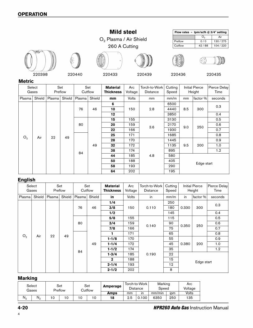
Mild steel
O2 Plasma / Air Shield
260 A Cutting
220440220398 220435220433 220436220439
SelectGases
SetPreflow
SetCutflow
Material
Thickness
ArcVoltage
Torch-to-WorkDistance
CuttingSpeed
Initial PierceHeight
Pierce DelayTime
Plasma Shield Plasma Shield Plasma Shield mm Volts mm mm/m mm factor % seconds
O2 Air 22 49
76 46
6
150 2.8
6500
8.5 3000.3
10 4440
12 3850 0.4
80
49
15 155
3.6
3130
9.0 250
0.5
20 159 2170 0.6
22 166 1930 0.7
84
25 171 1685 0.8
28 170
4.8
1445
9.5 200
0.9
32 172 1135 1.0
38 174 895 1.2
44 185 580
Edge start50 188 405
58 193 290
64 202 195
Metric
Select Gases
SetPreflow
SetCutflow
AmperageTorch-to-Work
DistanceMarkingSpeed
ArcVoltage
Amps mm in mm/min ipm VoltsN2 N2 10 10 10 10 18 2.5 0.100 6350 250 135
Marking
SelectGases
SetPreflow
SetCutflow
Material
Thickness
ArcVoltage
Torch-to-WorkDistance
CuttingSpeed
Initial PierceHeight
Pierce DelayTime
Plasma Shield Plasma Shield Plasma Shield in Volts in mm/m in factor % seconds
O2 Air 22 49
76 46
1/4
150 0.110
250
0.330 3000.3
3/8 180
1/2 145 0.4
80
49
5/8 155
0.140
115
0.350 250
0.5
3/4 159 90 0.6
7/8 166 75 0.7
84
1 171 65 0.8
1-1/8 170
0.190
55
0.380 200
0.9
1-1/4 172 45 1.0
1-1/2 174 35 1.2
1-3/4 185 22
Edge start2 188 15
2-1/4 193 12
2-1/2 202 8
English
Flow rates – lpm/scfh @ 3/4" setting
O2 Air
Preflow 0 / 0 130 / 275
Cutflow 42 / 88 104 / 220

OPERATION
HPR260 Auto Gas Instruction Manual 4-21
Stainless steel
N2 Plasma / N2 Shield
45 A Cutting
220202220173 220308220304 220180220201
Note: This process produces a darker cut edge than the 45 A, F5/N2 stainless steel process.
4
Metric
English
SelectGases
SetPreflow
SetCutflow
Material
Thickness
ArcVoltage
Torch-to-WorkDistance
CuttingSpeed
Initial PierceHeight
Pierce DelayTime
Plasma Shield Plasma Shield Plasma Shield mm Volts mm mm/m mm factor % seconds
N2 N2 35 5 62 49
0.8
94
2.5
6380
3.8 150
0.0
1 5880 0.1
1.2 5380
0.21.5 95 4630
2 97 3935
2.5 101 3270
3103
25500.3
4 1580
SelectGases
SetPreflow
SetCutflow
Material
Thickness
ArcVoltage
Torch-to-WorkDistance
CuttingSpeed
Initial PierceHeight
Pierce DelayTime
Plasma Shield Plasma Shield Plasma Shield in Volts in ipm in factor % seconds
N2 N2 35 5 62 49
.03694
0.100
240
0.150 150
0.0
.048 210 0.1
.060 95 180
0.2.075 97 160
.105 101 120
.135 103 75 0.3
Select Gases
SetPreflow
SetCutflow
AmperageTorch-to-Work
DistanceMarkingSpeed
ArcVoltage
Amps mm in mm/min ipm Volts
N2 N2 10 10 10 10 15 2.5 0.100 6350 250 85
Marking
Flow rates – lpm/scfh
N2
Preflow 24 / 51
Cutflow 75 / 159
OPERATION
4-22 HPR260 Auto Gas Instruction Manual4
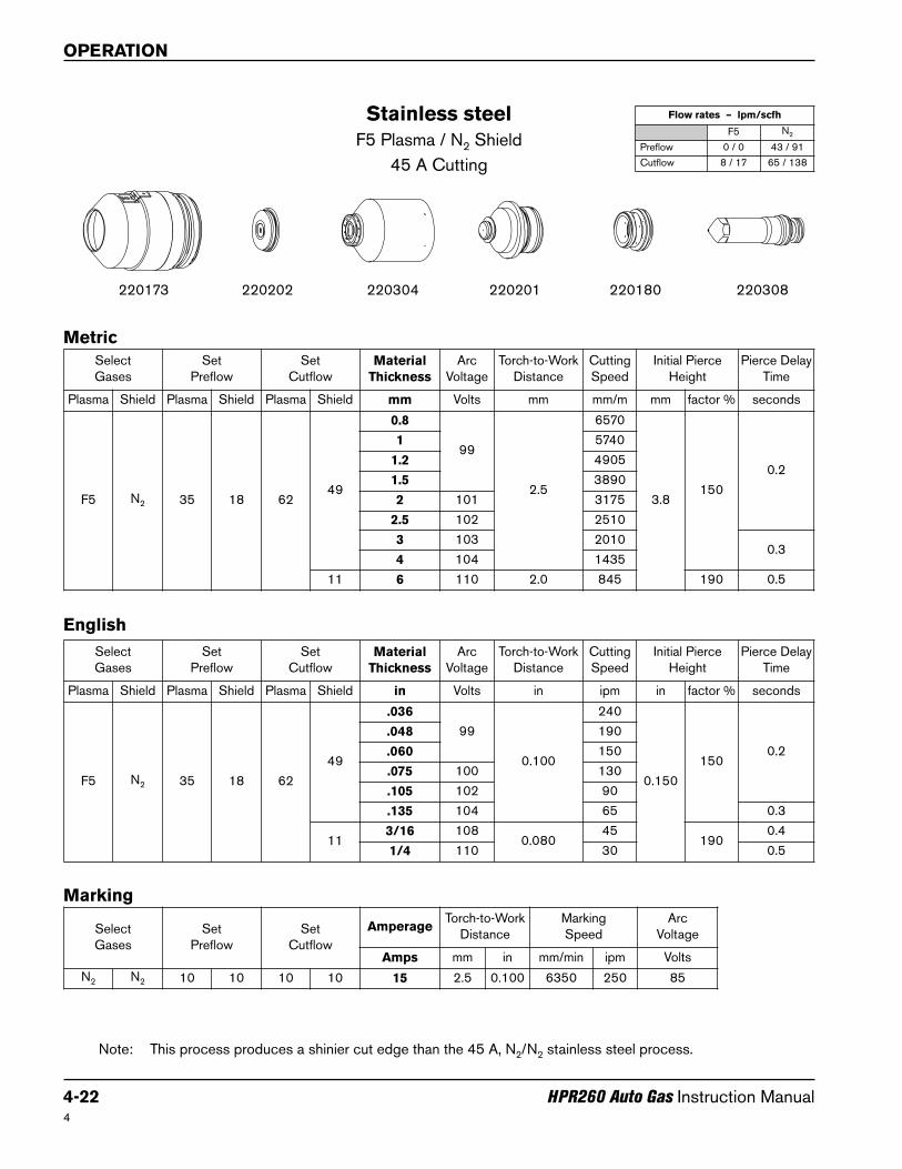
Stainless steel
F5 Plasma / N2 Shield
45 A Cutting
220202220173 220308220304 220180220201
Note: This process produces a shinier cut edge than the 45 A, N2/N2 stainless steel process.
Metric
English
SelectGases
SetPreflow
SetCutflow
Material
Thickness
ArcVoltage
Torch-to-WorkDistance
CuttingSpeed
Initial PierceHeight
Pierce DelayTime
Plasma Shield Plasma Shield Plasma Shield mm Volts mm mm/m mm factor % seconds
F5 N2 35 18 6249
0.8
99
2.5
6570
3.8150
0.2
1 5740
1.2 4905
1.5 3890
2 101 3175
2.5 102 2510
3 103 20100.3
4 104 1435
11 6 110 2.0 845 190 0.5
SelectGases
SetPreflow
SetCutflow
Material
Thickness
ArcVoltage
Torch-to-WorkDistance
CuttingSpeed
Initial PierceHeight
Pierce DelayTime
Plasma Shield Plasma Shield Plasma Shield in Volts in ipm in factor % seconds
F5 N2 35 18 62
49
.036
99
0.100
240
0.150
1500.2
.048 190
.060 150
.075 100 130
.105 102 90
.135 104 65 0.3
113/16 108
0.08045
1900.4
1/4 110 30 0.5
Select Gases
SetPreflow
SetCutflow
AmperageTorch-to-Work
DistanceMarkingSpeed
ArcVoltage
Amps mm in mm/min ipm Volts
N2 N2 10 10 10 10 15 2.5 0.100 6350 250 85
Marking
Flow rates – lpm/scfh
F5 N2
Preflow 0 / 0 43 / 91
Cutflow 8 / 17 65 / 138
OPERATION
HPR260 Auto Gas Instruction Manual 4-23
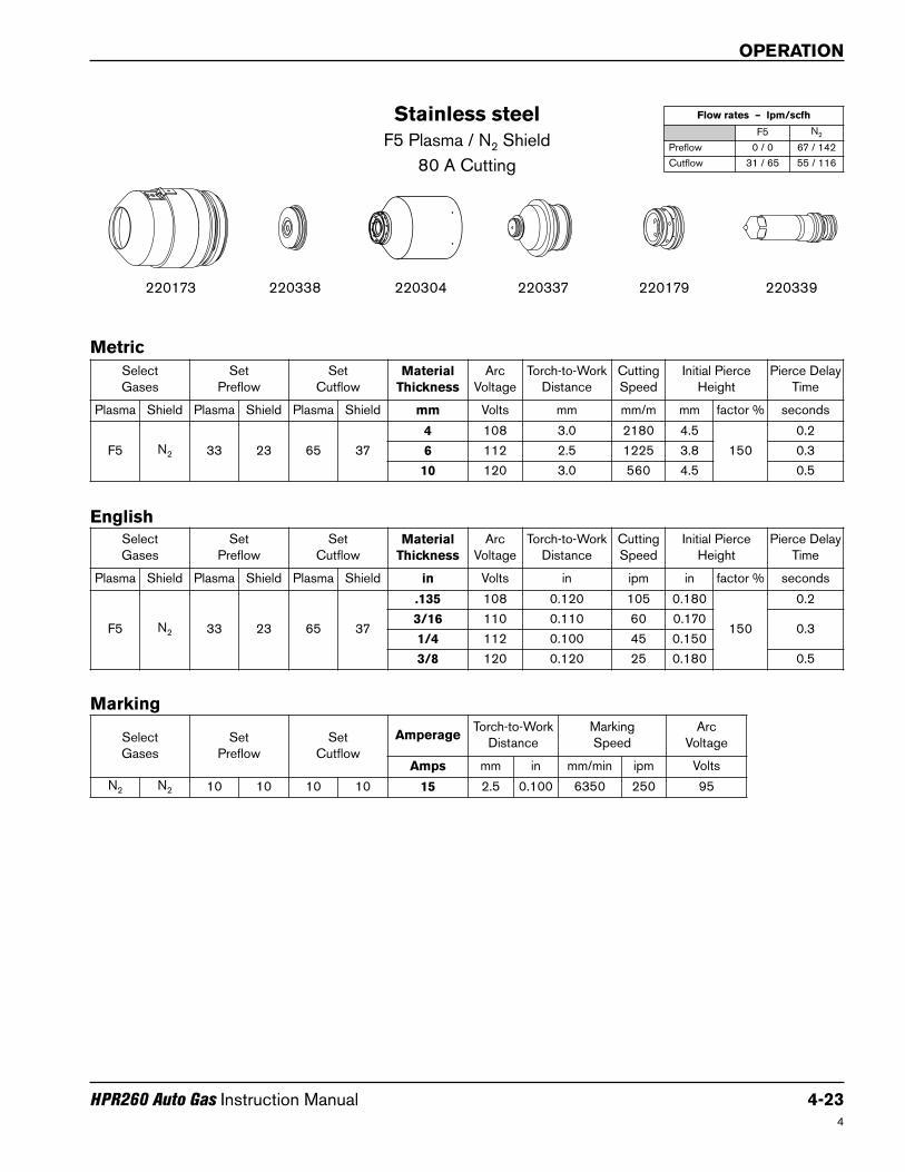
Stainless steel
F5 Plasma / N2 Shield
80 A Cutting
220338220173 220339220304 220179220337
4
Metric
English
SelectGases
SetPreflow
SetCutflow
Material
Thickness
ArcVoltage
Torch-to-WorkDistance
CuttingSpeed
Initial PierceHeight
Pierce DelayTime
Plasma Shield Plasma Shield Plasma Shield mm Volts mm mm/m mm factor % seconds
F5 N2 33 23 65 37
4 108 3.0 2180 4.5
150
0.2
6 112 2.5 1225 3.8 0.3
10 120 3.0 560 4.5 0.5
SelectGases
SetPreflow
SetCutflow
Material
Thickness
ArcVoltage
Torch-to-WorkDistance
CuttingSpeed
Initial PierceHeight
Pierce DelayTime
Plasma Shield Plasma Shield Plasma Shield in Volts in ipm in factor % seconds
F5 N2 33 23 65 37
.135 108 0.120 105 0.180
150
0.2
3/16 110 0.110 60 0.1700.3
1/4 112 0.100 45 0.150
3/8 120 0.120 25 0.180 0.5
Select Gases
SetPreflow
SetCutflow
AmperageTorch-to-Work
DistanceMarking Speed
ArcVoltage
Amps mm in mm/min ipm Volts
N2 N2 10 10 10 10 15 2.5 0.100 6350 250 95
Marking
Flow rates – lpm/scfh
F5 N2
Preflow 0 / 0 67 / 142
Cutflow 31 / 65 55 / 116

OPERATION
4-24 HPR260 Auto Gas Instruction Manual5
Stainless steel
N2 Plasma / N2 Shield
130 A Cutting
220198220173 220307220179220197220176
Note: This process produces a rougher, darker cut edge with more dross, and the cut edges are closer toperpendicular than the 130 A, H35/N2 process.
Metric
English
SelectGases
SetPreflow
SetCutflow
Material
Thickness
ArcVoltage
Torch-to-WorkDistance
CuttingSpeed
Initial PierceHeight
Pierce DelayTime
Plasma Shield Plasma Shield Plasma Shield in Volts in ipm in factor % seconds
N2 N2 19 51 75 23
1/4 1530.120
750.240
200
0.3
3/8 156 55 0.5
1/2 162 0.140 30 0.280 0.8
5/8 167 0.150 25Edge start
3/4 176 0.170 15
SelectGases
SetPreflow
SetCutflow
Material
Thickness
ArcVoltage
Torch-to-WorkDistance
CuttingSpeed
Initial PierceHeight
Pierce DelayTime
Plasma Shield Plasma Shield Plasma Shield mm Volts mm mm/m mm factor % seconds
N2 N2 19 51 75 23
6 1533.0
19606.0
200
0.3
10 156 1300 0.5
12 162 3.5 900 7.0 0.8
15 167 3.8 670Edge start
20 176 4.3 305
Select Gases
SetPreflow
SetCutflow
AmperageTorch-to-Work
DistanceMarking Speed
ArcVoltage
Amps mm in mm/min ipm Volts
N2 N2 10 10 10 10 18 2.5 0.100 6350 250 140
Marking
Flow rates – lpm/scfh
N2
Preflow 97 / 205
Cutflow 79 / 168
OPERATION
HPR260 Auto Gas Instruction Manual 4-25
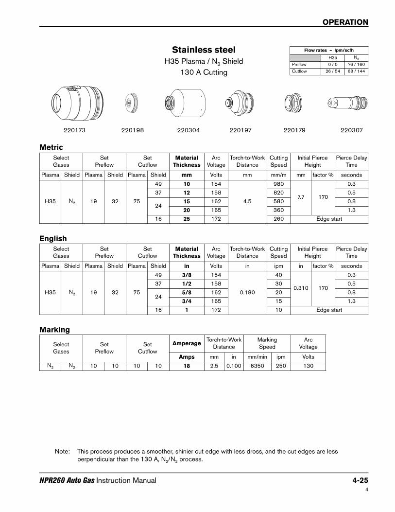
Stainless steel
H35 Plasma / N2 Shield
130 A Cutting
220198220173 220307220304 220179220197
Note: This process produces a smoother, shinier cut edge with less dross, and the cut edges are lessperpendicular than the 130 A, N2/N2 process.
4
Metric
English
SelectGases
SetPreflow
SetCutflow
Material
Thickness
ArcVoltage
Torch-to-WorkDistance
CuttingSpeed
Initial PierceHeight
Pierce DelayTime
Plasma Shield Plasma Shield Plasma Shield mm Volts mm mm/m mm factor % seconds
H35 N2 19 32 75
49 10 154
4.5
980
7.7 170
0.3
37 12 158 820 0.5
2415 162 580 0.8
20 165 360 1.3
16 25 172 260 Edge start
SelectGases
SetPreflow
SetCutflow
Material
Thickness
ArcVoltage
Torch-to-WorkDistance
CuttingSpeed
Initial PierceHeight
Pierce DelayTime
Plasma Shield Plasma Shield Plasma Shield in Volts in ipm in factor % seconds
H35 N2 19 32 75
49 3/8 154
0.180
40
0.310 170
0.3
37 1/2 158 30 0.5
245/8 162 20 0.8
3/4 165 15 1.3
16 1 172 10 Edge start
Select Gases
SetPreflow
SetCutflow
AmperageTorch-to-Work
DistanceMarking Speed
ArcVoltage
Amps mm in mm/min ipm Volts
N2 N2 10 10 10 10 18 2.5 0.100 6350 250 130
Marking
Flow rates – lpm/scfh
H35 N2
Preflow 0 / 0 76 / 160
Cutflow 26 / 54 68 / 144

OPERATION
4-26 HPR260 Auto Gas Instruction Manual5
Stainless steel
H35 and N2 Plasma / N2 Shield
130 A Cutting
220198220173 220307220304 220179220197
Note: This process produces a smoother, shinier cut edge with less dross, and the cut edges are lessperpendicular than the 130 A, N2/N2 process. Edge color is more silver than the H35/N2 process.
Metric
English
SelectGases
SetPreflow
SetCutflow
Material
Thickness
ArcVoltage
Torch-to-WorkDistance
CuttingSpeed
Initial PierceHeight
PierceDelayTime
Plasma Shield Plasma Shield Plasma ShieldMix
Gas 1Mix
Gas 2mm Volts mm mm/m mm factor % seconds
H35 N2 19 51 75
38
32 18
6 1503.0
18356.0
200
0.3
10 153 1195 0.3
27
12 160 3.5 875 7.0 0.5
15 168 3.8 670 7.6 0.8
20 176 4.3 305 7.7 180 1.3
SelectGases
SetPreflow
SetCutflow
Material
Thickness
ArcVoltage
Torch-to-WorkDistance
CuttingSpeed
Initial PierceHeight
PierceDelayTime
Plasma Shield Plasma Shield Plasma ShieldMix
Gas 1Mix
Gas 2in Volts in ipm in factor % seconds
H35 N2 19 51 75
38
32 18
1/4 1500.120
700.240
200
0.3
3/8 153 50 0.3
27
1/2 160 0.140 30 0.280 0.5
5/8 168 0.150 25 0.300 0.8
3/4 176 0.170 15 0.310 180 1.3
Select Gases
SetPreflow
SetCutflow
AmperageTorch-to-Work
DistanceMarking Speed
ArcVoltage
Amps mm in mm/min ipm Volts
N2 N2 10 10 10 10 18 2.5 0.100 6350 250 130
Marking
Flow rates – lpm/scfh
H35 N2
Preflow 0 / 0 97 / 205
Cutflow 13 / 28 71 / 150
OPERATION
HPR260 Auto Gas Instruction Manual 4-27
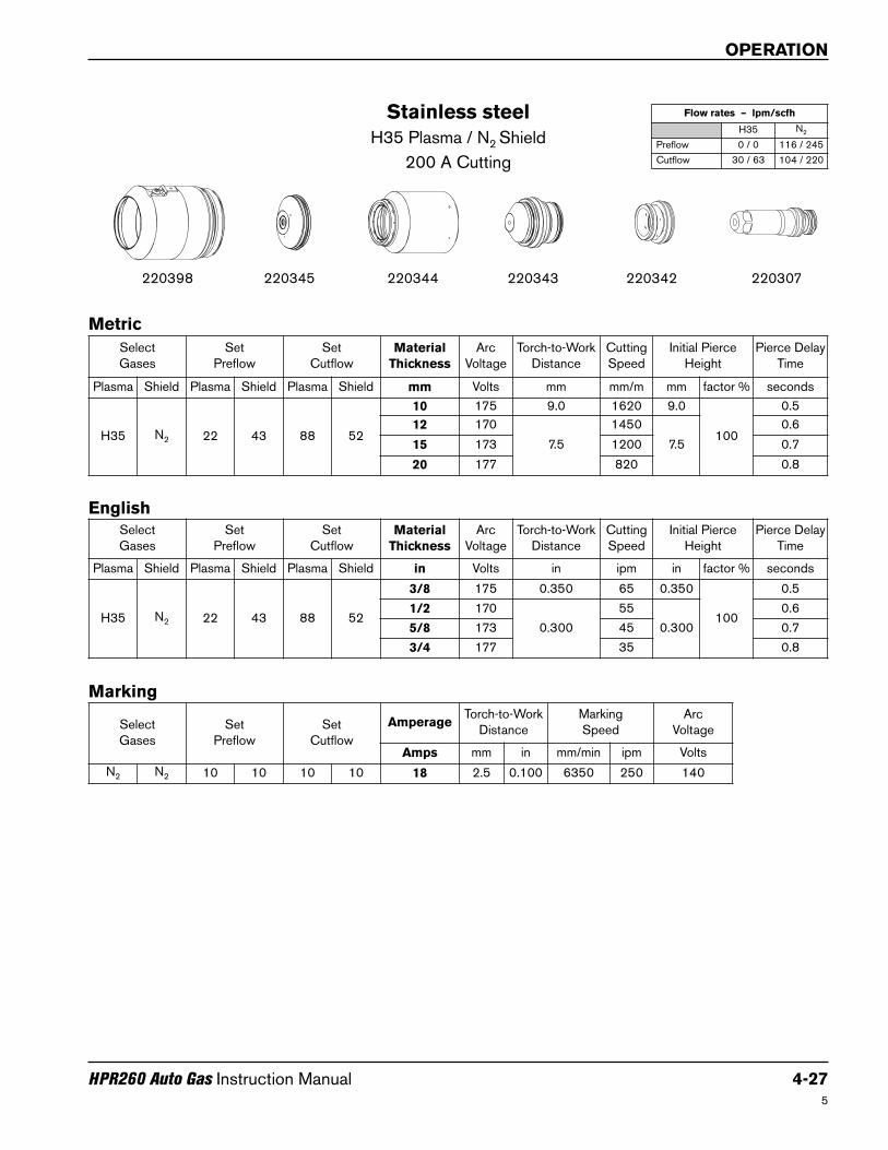
Stainless steel
H35 Plasma / N2 Shield
200 A Cutting
220345220398 220307220344 220342220343
5
Metric
English
SelectGases
SetPreflow
SetCutflow
Material
Thickness
ArcVoltage
Torch-to-WorkDistance
CuttingSpeed
Initial PierceHeight
Pierce DelayTime
Plasma Shield Plasma Shield Plasma Shield mm Volts mm mm/m mm factor % seconds
H35 N2 22 43 88 52
10 175 9.0 1620 9.0
100
0.5
12 170
7.5
1450
7.5
0.6
15 173 1200 0.7
20 177 820 0.8
SelectGases
SetPreflow
SetCutflow
Material
Thickness
ArcVoltage
Torch-to-WorkDistance
CuttingSpeed
Initial PierceHeight
Pierce DelayTime
Plasma Shield Plasma Shield Plasma Shield in Volts in ipm in factor % seconds
H35 N2 22 43 88 52
3/8 175 0.350 65 0.350
100
0.5
1/2 170
0.300
55
0.300
0.6
5/8 173 45 0.7
3/4 177 35 0.8
Select Gases
SetPreflow
SetCutflow
AmperageTorch-to-Work
DistanceMarking Speed
ArcVoltage
Amps mm in mm/min ipm Volts
N2 N2 10 10 10 10 18 2.5 0.100 6350 250 140
Marking
Flow rates – lpm/scfh
H35 N2
Preflow 0 / 0 116 / 245
Cutflow 30 / 63 104 / 220
OPERATION
4-28 HPR260 Auto Gas Instruction Manual4
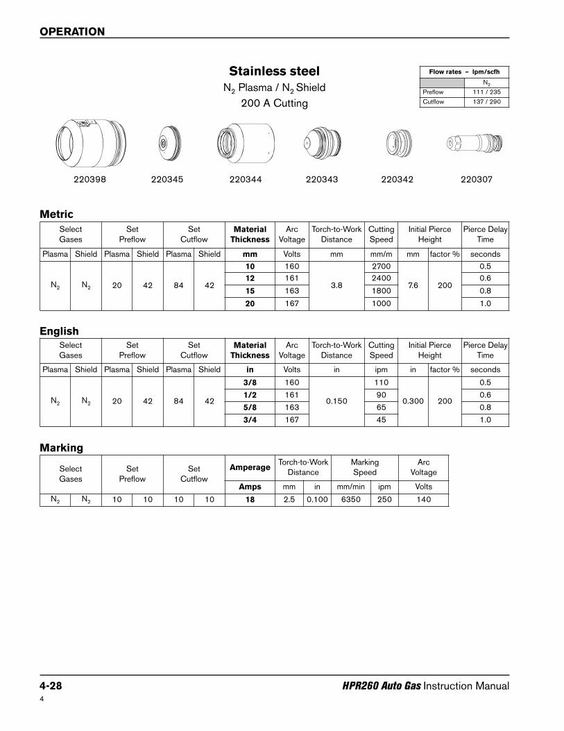
Stainless steel
N2 Plasma / N2 Shield
200 A Cutting
220345220398 220307220344 220342220343
Metric
English
SelectGases
SetPreflow
SetCutflow
Material
Thickness
ArcVoltage
Torch-to-WorkDistance
CuttingSpeed
Initial PierceHeight
Pierce DelayTime
Plasma Shield Plasma Shield Plasma Shield mm Volts mm mm/m mm factor % seconds
N2 N2 20 42 84 42
10 160
3.8
2700
7.6 200
0.5
12 161 2400 0.6
15 163 1800 0.8
20 167 1000 1.0
SelectGases
SetPreflow
SetCutflow
Material
Thickness
ArcVoltage
Torch-to-WorkDistance
CuttingSpeed
Initial PierceHeight
Pierce DelayTime
Plasma Shield Plasma Shield Plasma Shield in Volts in ipm in factor % seconds
N2 N2 20 42 84 42
3/8 160
0.150
110
0.300 200
0.5
1/2 161 90 0.6
5/8 163 65 0.8
3/4 167 45 1.0
Select Gases
SetPreflow
SetCutflow
AmperageTorch-to-Work
DistanceMarking Speed
ArcVoltage
Amps mm in mm/min ipm Volts
N2 N2 10 10 10 10 18 2.5 0.100 6350 250 140
Marking
Flow rates – lpm/scfh
N2
Preflow 111 / 235
Cutflow 137 / 290

OPERATION
HPR260 Auto Gas Instruction Manual 4-29
Stainless steel
H35 and N2 Plasma / N2 Shield
200 A Cutting
220345220398 220307220344 220342220343
5
Metric
English
SelectGases
SetPreflow
SetCutflow
Material
Thickness
ArcVoltage
Torch-to-WorkDistance
CuttingSpeed
Initial PierceHeight
PierceDelayTime
Plasma Shield Plasma Shield Plasma ShieldMix
Gas 1Mix
Gas 2mm Volts mm mm/m mm factor % seconds
H35 N2 23 41 87 41 42 20
10 1614.0
19008.0 200
0.5
12 162 1800 0.6
15 167 4.6 1600 7.0150
0.8
20 171 5.1 1000 7.5 1.0
SelectGases
SetPreflow
SetCutflow
Material
Thickness
ArcVoltage
Torch-to-WorkDistance
CuttingSpeed
Initial PierceHeight
PierceDelayTime
Plasma Shield Plasma Shield Plasma ShieldMix
Gas 1Mix
Gas 2in Volts in ipm in factor % seconds
H35 N2 23 41 87 41 42 20
3/8 1610.160
750.320 200
0.5
1/2 162 70 0.6
5/8 167 0.180 60 0.270150
0.8
3/4 171 0.200 45 0.300 1.0
Select Gases
SetPreflow
SetCutflow
AmperageTorch-to-Work
DistanceMarking Speed
ArcVoltage
Amps mm in mm/min ipm Volts
N2 N2 10 10 10 10 18 2.5 0.100 6350 250 140
Marking
Flow rates – lpm/scfh
H35 N2
Preflow 0 / 0 116 / 245
Cutflow 11 / 24 118 / 250
OPERATION
4-30 HPR260 Auto Gas Instruction Manual4
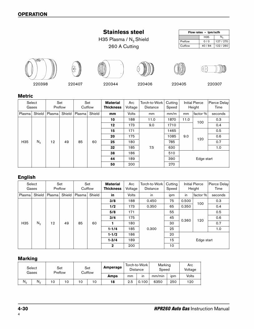
Stainless steel
H35 Plasma / N2 Shield
260 A Cutting
220407220398 220307220344 220405220406
Metric
English
Select Gases
SetPreflow
SetCutflow
AmperageTorch-to-Work
DistanceMarkingSpeed
ArcVoltage
Amps mm in mm/min ipm Volts
N2 N2 10 10 10 10 18 2.5 0.100 6350 250 120
Marking
SelectGases
SetPreflow
SetCutflow
Material
Thickness
ArcVoltage
Torch-to-WorkDistance
CuttingSpeed
Initial PierceHeight
Pierce DelayTime
Plasma Shield Plasma Shield Plasma Shield mm Volts mm mm/m mm factor % seconds
H35 N2 12 49 85 60
10 188 11.0 1870 11.0100
0.3
12 173 9.0 1710
9.0
0.4
15 171
7.5
1465
120
0.5
20 175 1085 0.6
25 180 785 0.7
32 185 630 1.0
38 186 510
Edge start44 189 390
50 200 270
SelectGases
SetPreflow
SetCutflow
Material
Thickness
ArcVoltage
Torch-to-WorkDistance
CuttingSpeed
Initial PierceHeight
Pierce DelayTime
Plasma Shield Plasma Shield Plasma Shield in Volts in ipm in factor % seconds
H35 N2 12 49 85 60
3/8 188 0.450 75 0.500100
0.3
1/2 173 0.350 65 0.350 0.4
5/8 171
0.300
55
0.360 120
0.5
3/4 175 45 0.6
1 180 30 0.7
1-1/4 185 25 1.0
1-1/2 186 20
Edge start1-3/4 189 15
2 200 10
Flow rates – lpm/scfh
H35 N2
Preflow 0 / 0 127 / 270
Cutflow 40 / 84 122 / 260
OPERATION
HPR260 Auto Gas Instruction Manual 4-31
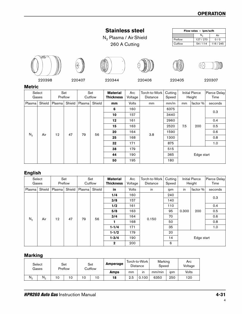
Stainless steel
N2 Plasma / Air Shield
260 A Cutting
220407220398 220307220344 220405220406
4
Metric
English
SelectGases
SetPreflow
SetCutflow
Material
Thickness
ArcVoltage
Torch-to-WorkDistance
CuttingSpeed
Initial PierceHeight
Pierce DelayTime
Plasma Shield Plasma Shield Plasma Shield mm Volts mm mm/m mm factor % seconds
N2 Air 12 47 79 56
6 160
3.8
6375
7.5 200
0.310 157 3440
12 161 2960 0.4
15 163 2520 0.5
20 164 1590 0.6
25 168 1300 0.8
32 171 875 1.0
38 179 515
Edge start44 190 365
50 195 180
SelectGases
SetPreflow
SetCutflow
Material
Thickness
ArcVoltage
Torch-to-WorkDistance
CuttingSpeed
Initial PierceHeight
Pierce DelayTime
Plasma Shield Plasma Shield Plasma Shield in Volts in ipm in factor % seconds
N2 Air 12 47 79 56
1/4 160
0.150
240
0.300 200
0.33/8 157 140
1/2 161 110 0.4
5/8 163 95 0.5
3/4 164 70 0.6
1 168 50 0.8
1-1/4 171 35 1.0
1-1/2 179 20
Edge start1-3/4 190 14
2 200 6
Select Gases
SetPreflow
SetCutflow
AmperageTorch-to-Work
DistanceMarking Speed
ArcVoltage
Amps mm in mm/min ipm Volts
N2 N2 10 10 10 10 18 2.5 0.100 6350 250 120
Marking
Flow rates – lpm/scfh
N2 Air
Preflow 127 / 270 0 / 0
Cutflow 54 / 114 116 / 245

OPERATION
4-32 HPR260 Auto Gas Instruction Manual4
Stainless steel
H35 and N2 Plasma / N2 Shield
260 A Cutting
220407220398 220307220344 220405220406
Metric
English
SelectGases
SetPreflow
SetCutflow
Material
Thickness
ArcVoltage
Torch-to-WorkDistance
CuttingSpeed
Initial PierceHeight
PierceDelayTime
Plasma Shield Plasma Shield Plasma ShieldMix
Gas 1Mix
Gas 2mm Volts mm mm/m mm factor % seconds
H35 N2 12 49 87 60
60 21
6 170
4.0
3980
8.0 200
0.310 175 2190
12 176 1790 0.5
15 177 1650 0.7
20 179 1320 0.8
40 26
25 182 920 1.0
32 186 755 1.2
38 189 510
Edge start44 195 390
50 202 270
SelectGases
SetPreflow
SetCutflow
Material
Thickness
ArcVoltage
Torch-to-WorkDistance
CuttingSpeed
Initial PierceHeight
PierceDelayTime
Plasma Shield Plasma Shield Plasma ShieldMix
Gas 1Mix
Gas 2in Volts in ipm in factor % seconds
H35 N2 12 49 87 60
60 21
1/4 170
0.160
150
0.320 200
0.33/8 175 90
1/2 17665
0.5
5/8 177 0.7
3/4 179 55 0.8
40 26
1 182 35 1.0
1-1/4 186 30 1.2
1-1/2 189 20
Edge start1-3/4 187 15
2 202 10
Select Gases
SetPreflow
SetCutflow
AmperageTorch-to-Work
DistanceMarking Speed
ArcVoltage
Amps mm in mm/min ipm Volts
N2 N2 10 10 10 10 18 2.5 0.100 6350 250 120
Marking
Flow rates – lpm/scfh
H35 N2
Preflow 0 / 0 132 / 280
Cutflow 13 / 27 163 / 345
OPERATION
HPR260 Auto Gas Instruction Manual 4-33
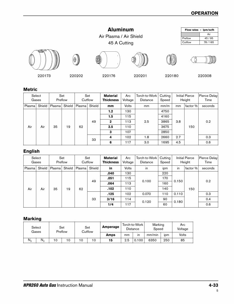
Aluminum
Air Plasma / Air Shield
45 A Cutting
220202220173 220308220176 220180220201
5
Metric
English
SelectGases
SetPreflow
SetCutflow
Material
Thickness
ArcVoltage
Torch-to-WorkDistance
CuttingSpeed
Initial PierceHeight
Pierce DelayTime
Plasma Shield Plasma Shield Plasma Shield mm Volts mm mm/m mm factor % seconds
Air Air 35 19 62
49
1.2 130
2.5
4750
3.8
150
0.2
1.5 115 4160
2 113 3865
2.5 110 3675
3 107 2850
334 102 1.8 2660 2.7 0.3
6 117 3.0 1695 4.5 0.6
SelectGases
SetPreflow
SetCutflow
Material
Thickness
ArcVoltage
Torch-to-WorkDistance
CuttingSpeed
Initial PierceHeight
Pierce DelayTime
Plasma Shield Plasma Shield Plasma Shield in Volts in ipm in factor % seconds
Air Air 35 19 62
49
.040 130
0.100
220
0.150
150
0.2.051 115 170
.064 113 160
.102 110 140
33
.125 102 0.070 110 0.110 0.3
3/16 1140.120
900.180
0.4
1/4 117 60 0.6
Select Gases
SetPreflow
SetCutflow
AmperageTorch-to-Work
DistanceMarking Speed
ArcVoltage
Amps mm in mm/min ipm Volts
N2 N2 10 10 10 10 15 2.5 0.100 6350 250 85
Marking
Flow rates – lpm/scfh
Air
Preflow 45 / 95
Cutflow 78 / 165
OPERATION
4-34 HPR260 Auto Gas Instruction Manual4
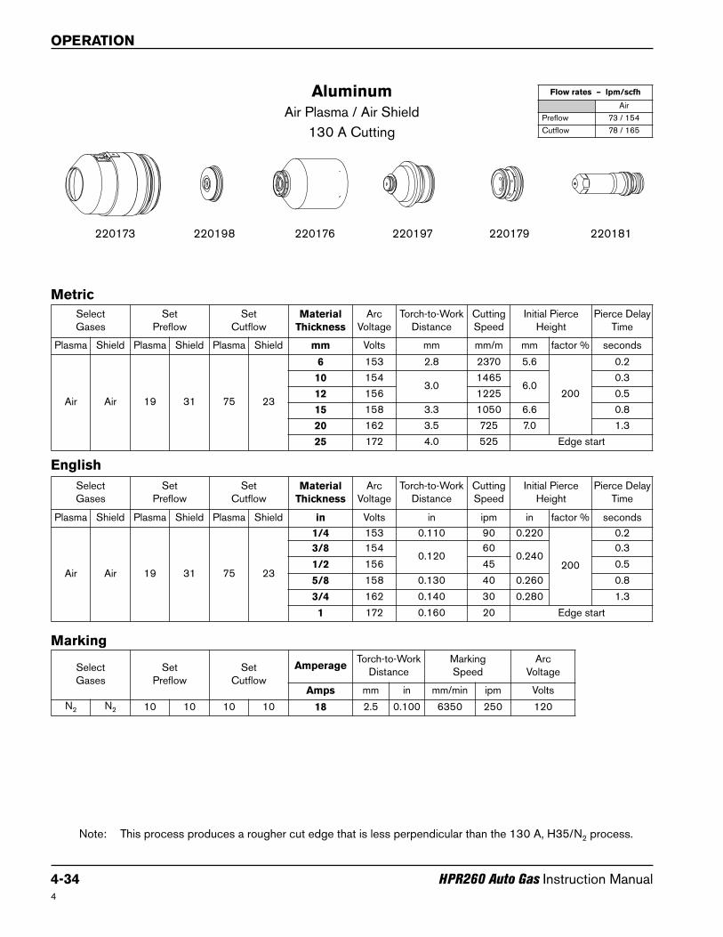
Aluminum
Air Plasma / Air Shield
130 A Cutting
220198220173 220181220176 220179220197
Note: This process produces a rougher cut edge that is less perpendicular than the 130 A, H35/N2 process.
Metric
English
SelectGases
SetPreflow
SetCutflow
Material
Thickness
ArcVoltage
Torch-to-WorkDistance
CuttingSpeed
Initial PierceHeight
Pierce DelayTime
Plasma Shield Plasma Shield Plasma Shield mm Volts mm mm/m mm factor % seconds
Air Air 19 31 75 23
6 153 2.8 2370 5.6
200
0.2
10 1543.0
14656.0
0.3
12 156 1225 0.5
15 158 3.3 1050 6.6 0.8
20 162 3.5 725 7.0 1.3
25 172 4.0 525 Edge start
SelectGases
SetPreflow
SetCutflow
Material
Thickness
ArcVoltage
Torch-to-WorkDistance
CuttingSpeed
Initial PierceHeight
Pierce DelayTime
Plasma Shield Plasma Shield Plasma Shield in Volts in ipm in factor % seconds
Air Air 19 31 75 23
1/4 153 0.110 90 0.220
200
0.2
3/8 1540.120
600.240
0.3
1/2 156 45 0.5
5/8 158 0.130 40 0.260 0.8
3/4 162 0.140 30 0.280 1.3
1 172 0.160 20 Edge start
Select Gases
SetPreflow
SetCutflow
AmperageTorch-to-Work
DistanceMarking Speed
ArcVoltage
Amps mm in mm/min ipm Volts
N2 N2 10 10 10 10 18 2.5 0.100 6350 250 120
Marking
Flow rates – lpm/scfh
Air
Preflow 73 / 154
Cutflow 78 / 165
OPERATION
HPR260 Auto Gas Instruction Manual 4-35
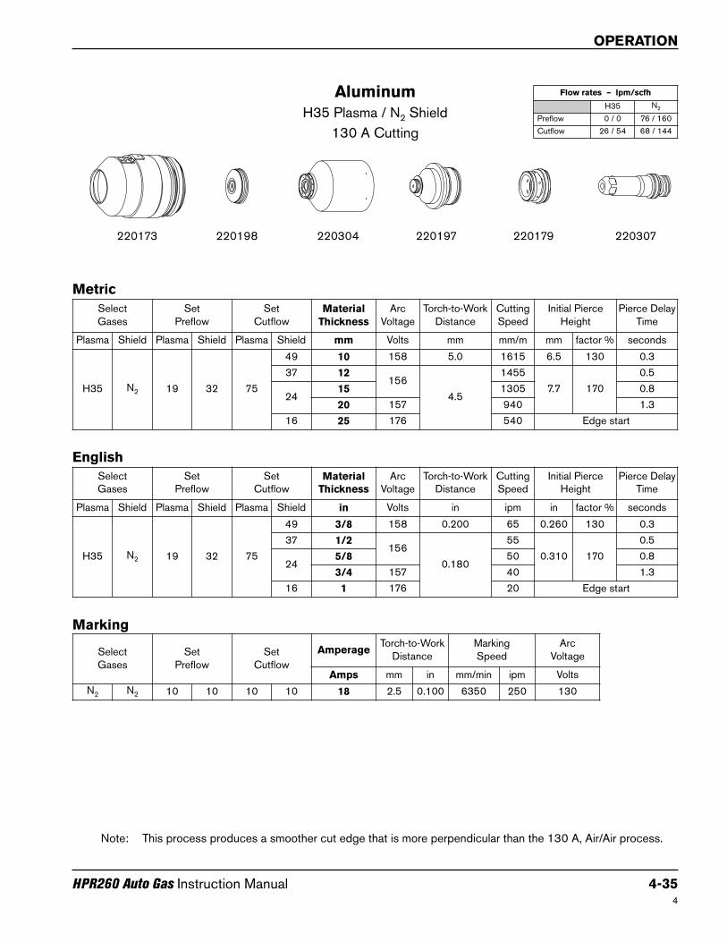
Aluminum
H35 Plasma / N2 Shield
130 A Cutting
220198220173 220307220304 220179220197
Note: This process produces a smoother cut edge that is more perpendicular than the 130 A, Air/Air process.
4
Metric
English
SelectGases
SetPreflow
SetCutflow
Material
Thickness
ArcVoltage
Torch-to-WorkDistance
CuttingSpeed
Initial PierceHeight
Pierce DelayTime
Plasma Shield Plasma Shield Plasma Shield mm Volts mm mm/m mm factor % seconds
H35 N2 19 32 75
49 10 158 5.0 1615 6.5 130 0.3
37 12156
4.5
1455
7.7 170
0.5
2415 1305 0.8
20 157 940 1.3
16 25 176 540 Edge start
SelectGases
SetPreflow
SetCutflow
Material
Thickness
ArcVoltage
Torch-to-WorkDistance
CuttingSpeed
Initial PierceHeight
Pierce DelayTime
Plasma Shield Plasma Shield Plasma Shield in Volts in ipm in factor % seconds
H35 N2 19 32 75
49 3/8 158 0.200 65 0.260 130 0.3
37 1/2156
0.180
55
0.310 170
0.5
245/8 50 0.8
3/4 157 40 1.3
16 1 176 20 Edge start
Select Gases
SetPreflow
SetCutflow
AmperageTorch-to-Work
DistanceMarking Speed
ArcVoltage
Amps mm in mm/min ipm Volts
N2 N2 10 10 10 10 18 2.5 0.100 6350 250 130
Marking
Flow rates – lpm/scfh
H35 N2
Preflow 0 / 0 76 / 160
Cutflow 26 / 54 68 / 144

OPERATION
4-36 HPR260 Auto Gas Instruction Manual
Aluminum
H35 and N2 Plasma / N2 Shield
130 A Cutting
220198220173 220307220304 220179220197
5
Metric
English
SelectGases
SetPreflow
SetCutflow
Material
Thickness
ArcVoltage
Torch-to-WorkDistance
CuttingSpeed
Initial PierceHeight
PierceDelayTime
Plasma Shield Plasma Shield Plasma ShieldMix
Gas 1Mix
Gas 2mm Volts mm mm/m mm factor % seconds
H35 N2 19 51 75 27 32 18
6 1563.5
22157.0
200
0.310 158 1615
12 159
3.0
1455
6.0
0.5
15 160 1215 0.8
20 163 815 1.3
SelectGases
SetPreflow
SetCutflow
Material
Thickness
ArcVoltage
Torch-to-WorkDistance
CuttingSpeed
Initial PierceHeight
PierceDelayTime
Plasma Shield Plasma Shield Plasma ShieldMix
Gas 1Mix
Gas 2in Volts in ipm in factor % seconds
H35 N2 19 51 75 27 32 18
1/4 1560.140
850.280
200
0.33/8 158 65
1/2 159
0.120
55
0.240
0.5
5/8 160 45 0.8
3/4 163 35 1.3
Select Gases
SetPreflow
SetCutflow
AmperageTorch-to-Work
DistanceMarking Speed
ArcVoltage
Amps mm in mm/min ipm Volts
N2 N2 10 10 10 10 18 2.5 0.100 6350 250 130
Marking
Flow rates – lpm/scfh
H35 N2
Preflow 0 / 0 97 / 205
Cutflow 13 / 28 71 / 150
OPERATION
HPR260 Auto Gas Instruction Manual 4-374
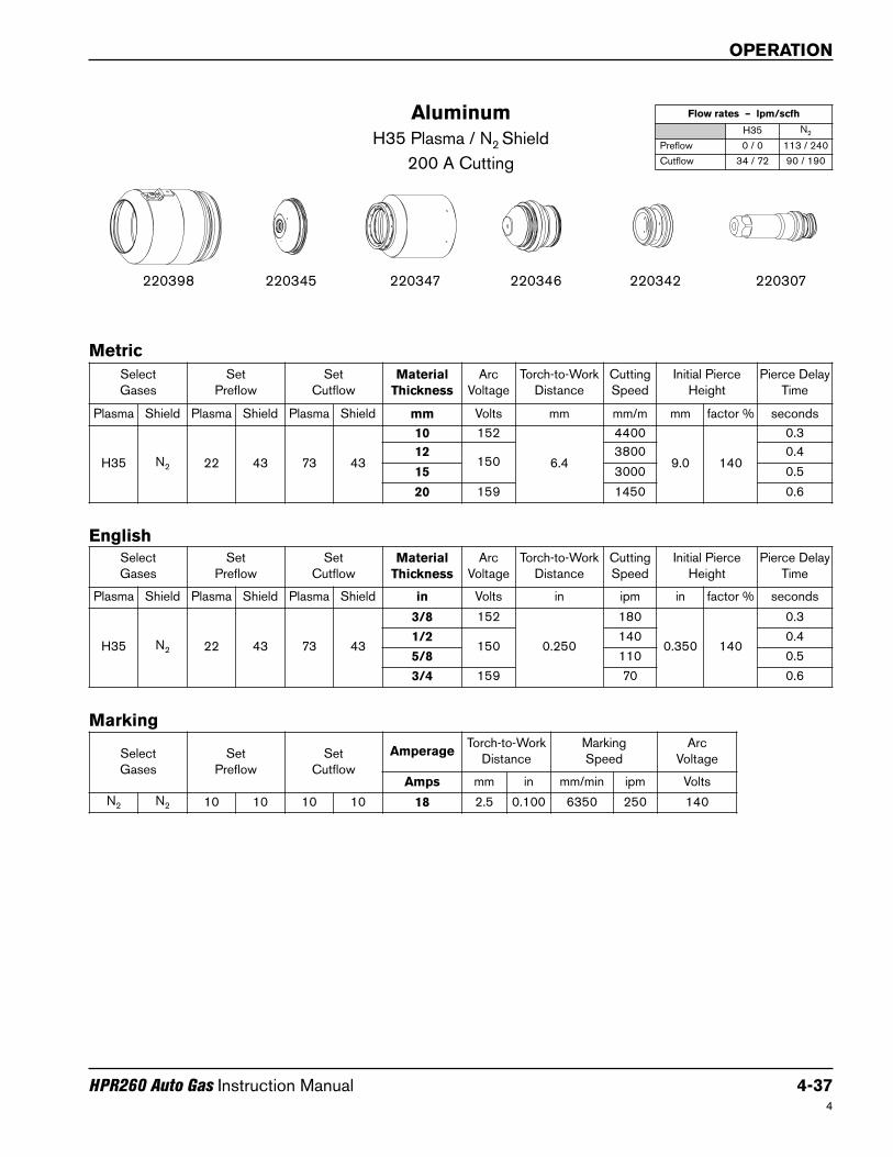
Aluminum
H35 Plasma / N2 Shield
200 A Cutting
220345220398 220307220347 220342220346
Metric
English
SelectGases
SetPreflow
SetCutflow
Material
Thickness
ArcVoltage
Torch-to-WorkDistance
CuttingSpeed
Initial PierceHeight
Pierce DelayTime
Plasma Shield Plasma Shield Plasma Shield mm Volts mm mm/m mm factor % seconds
H35 N2 22 43 73 43
10 152
6.4
4400
9.0 140
0.3
12150
3800 0.4
15 3000 0.5
20 159 1450 0.6
SelectGases
SetPreflow
SetCutflow
Material
Thickness
ArcVoltage
Torch-to-WorkDistance
CuttingSpeed
Initial PierceHeight
Pierce DelayTime
Plasma Shield Plasma Shield Plasma Shield in Volts in ipm in factor % seconds
H35 N2 22 43 73 43
3/8 152
0.250
180
0.350 140
0.3
1/2150
140 0.4
5/8 110 0.5
3/4 159 70 0.6
Select Gases
SetPreflow
SetCutflow
AmperageTorch-to-Work
DistanceMarking Speed
ArcVoltage
Amps mm in mm/min ipm Volts
N2 N2 10 10 10 10 18 2.5 0.100 6350 250 140
Marking
Flow rates – lpm/scfh
H35 N2
Preflow 0 / 0 113 / 240
Cutflow 34 / 72 90 / 190

OPERATION
4-38 HPR260 Auto Gas Instruction Manual4
Aluminum
N2 Plasma / N2 Shield
200 A Cutting
220345220398 220307220347 220342220346
Metric
English
SelectGases
SetPreflow
SetCutflow
Material
Thickness
ArcVoltage
Torch-to-WorkDistance
CuttingSpeed
Initial PierceHeight
Pierce DelayTime
Plasma Shield Plasma Shield Plasma Shield mm Volts mm mm/m mm factor % seconds
N2 N2 22 43 73 43
10158
6.4
4750
9.0 140
0.4
12 3500 0.5
15 166 2350 0.6
20 165 1000 0.8
SelectGases
SetPreflow
SetCutflow
Material
Thickness
ArcVoltage
Torch-to-WorkDistance
CuttingSpeed
Initial PierceHeight
Pierce DelayTime
Plasma Shield Plasma Shield Plasma Shield in Volts in ipm in factor % seconds
N2 N2 22 43 73 43
3/8158
0.250
200
0.350 140
0.4
1/2 120 0.5
5/8 166 80 0.6
3/4 165 50 0.8
Select Gases
SetPreflow
SetCutflow
AmperageTorch-to-Work
DistanceMarking Speed
ArcVoltage
Amps mm in mm/min ipm Volts
N2 N2 10 10 10 10 18 2.5 0.100 6350 250 140
Marking
Flow rates – lpm/scfh
N2
Preflow 113 / 240
Cutflow 135 / 287
OPERATION
HPR260 Auto Gas Instruction Manual 4-39
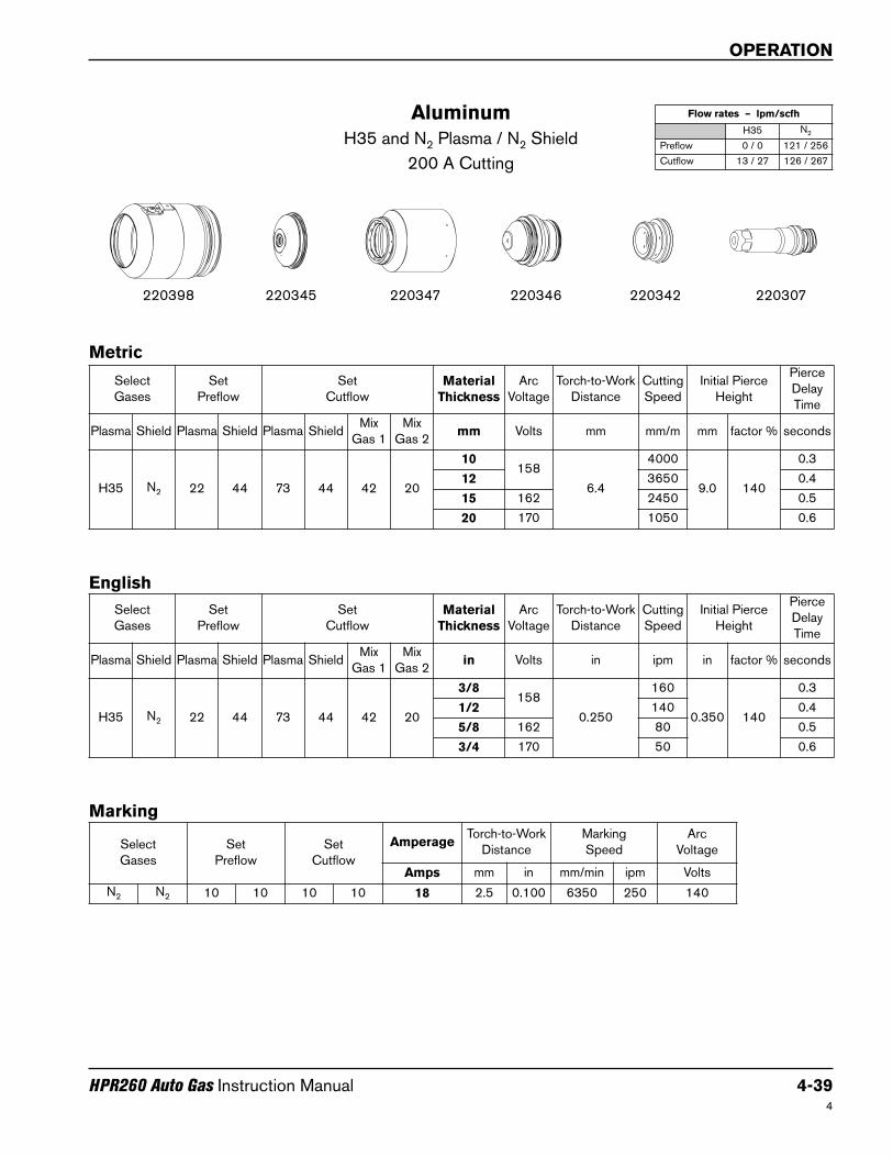
Aluminum
H35 and N2 Plasma / N2 Shield
200 A Cutting
220345220398 220307220347 220342220346
4
Metric
English
SelectGases
SetPreflow
SetCutflow
Material
Thickness
ArcVoltage
Torch-to-WorkDistance
CuttingSpeed
Initial PierceHeight
PierceDelayTime
Plasma Shield Plasma Shield Plasma ShieldMix
Gas 1Mix
Gas 2mm Volts mm mm/m mm factor % seconds
H35 N2 22 44 73 44 42 20
10158
6.4
4000
9.0 140
0.3
12 3650 0.4
15 162 2450 0.5
20 170 1050 0.6
SelectGases
SetPreflow
SetCutflow
Material
Thickness
ArcVoltage
Torch-to-WorkDistance
CuttingSpeed
Initial PierceHeight
PierceDelayTime
Plasma Shield Plasma Shield Plasma ShieldMix
Gas 1Mix
Gas 2in Volts in ipm in factor % seconds
H35 N2 22 44 73 44 42 20
3/8158
0.250
160
0.350 140
0.3
1/2 140 0.4
5/8 162 80 0.5
3/4 170 50 0.6
Select Gases
SetPreflow
SetCutflow
AmperageTorch-to-Work
DistanceMarking Speed
ArcVoltage
Amps mm in mm/min ipm Volts
N2 N2 10 10 10 10 18 2.5 0.100 6350 250 140
Marking
Flow rates – lpm/scfh
H35 N2
Preflow 0 / 0 121 / 256
Cutflow 13 / 27 126 / 267

OPERATION
4-40 HPR260 Auto Gas Instruction Manual4
Aluminum
H35 Plasma / N2 Shield
260 A Cutting
220407220398 220307220344 220405220406
Metric
English
SelectGases
SetPreflow
SetCutflow
Material
Thickness
ArcVoltage
Torch-to-WorkDistance
CuttingSpeed
Initial PierceHeight
Pierce DelayTime
Plasma Shield Plasma Shield Plasma Shield mm Volts mm mm/m mm factor % seconds
H35 N2 12 49 76 58
6170
11.0 7200 11.0100
0.2
10 10.0 6120 10.0 0.4
12 162
7.6
5160
8.5 110
0.5
15 163 37200.6
20 166 2230
25 174 1930 11.0 150 0.8
32 175 1510
Edge start38 176 1150
44 183 670
50 190 390
SelectGases
SetPreflow
SetCutflow
Material
Thickness
ArcVoltage
Torch-to-WorkDistance
CuttingSpeed
Initial PierceHeight
Pierce DelayTime
Plasma Shield Plasma Shield Plasma Shield in Volts in ipm in factor % seconds
H35 N2 12 49 76 58
1/4170
0.450 280 0.450100
0.2
3/8 0.400 250 0.400 0.4
1/2 162
0.300
190
0.330 110
0.5
5/8 163 1300.6
3/4 166 90
1 174 75 0.450 150 0.8
1-1/4 175 60
Edge start1-1/2 176 45
1-3/4 183 25
2 190 14
Select Gases
SetPreflow
SetCutflow
AmperageTorch-to-Work
DistanceMarking Speed
ArVoltage
Amps mm in mm/min ipm Volts
N2 N2 10 10 10 10 18 2.5 0.100 6350 250 120
Marking
Flow rates – lpm/scfh
H35 N2
Preflow 0 / 0 127 / 270
Cutflow 33 / 70 118 / 250
OPERATION
HPR260 Auto Gas Instruction Manual 4-41
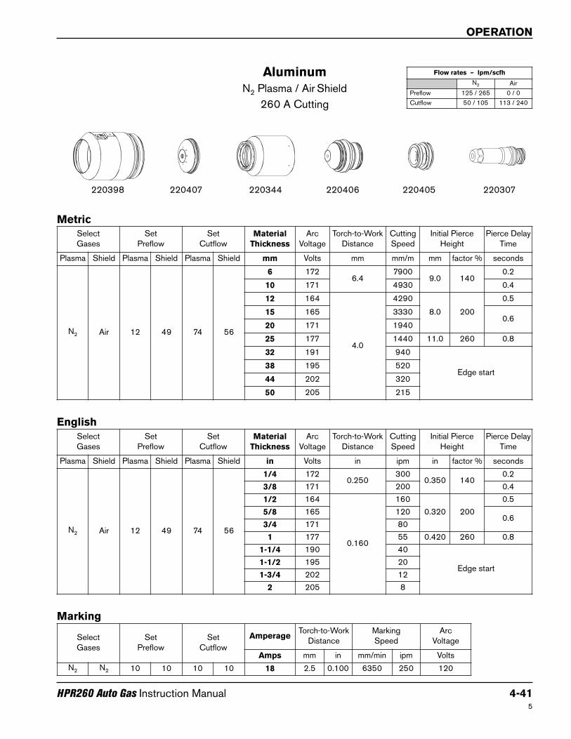
Aluminum
N2 Plasma / Air Shield
260 A Cutting
220407220398 220307220344 220405220406
5
Metric
English
SelectGases
SetPreflow
SetCutflow
Material
Thickness
ArcVoltage
Torch-to-WorkDistance
CuttingSpeed
Initial PierceHeight
Pierce DelayTime
Plasma Shield Plasma Shield Plasma Shield mm Volts mm mm/m mm factor % seconds
N2 Air 12 49 74 56
6 1726.4
79009.0 140
0.2
10 171 4930 0.4
12 164
4.0
4290
8.0 200
0.5
15 165 33300.6
20 171 1940
25 177 1440 11.0 260 0.8
32 191 940
Edge start38 195 520
44 202 320
50 205 215
SelectGases
SetPreflow
SetCutflow
Material
Thickness
ArcVoltage
Torch-to-WorkDistance
CuttingSpeed
Initial PierceHeight
Pierce DelayTime
Plasma Shield Plasma Shield Plasma Shield in Volts in ipm in factor % seconds
N2 Air 12 49 74 56
1/4 1720.250
3000.350 140
0.2
3/8 171 200 0.4
1/2 164
0.160
160
0.320 200
0.5
5/8 165 1200.6
3/4 171 80
1 177 55 0.420 260 0.8
1-1/4 190 40
Edge start1-1/2 195 20
1-3/4 202 12
2 205 8
Select Gases
SetPreflow
SetCutflow
AmperageTorch-to-Work
DistanceMarking Speed
ArcVoltage
Amps mm in mm/min ipm Volts
N2 N2 10 10 10 10 18 2.5 0.100 6350 250 120
Marking
Flow rates – lpm/scfh
N2 Air
Preflow 125 / 265 0 / 0
Cutflow 50 / 105 113 / 240