cut 65 cnc - topgun welding...
TRANSCRIPT
CUT 65 CNC
AIR PLASMA CUTTER
IMPORTANT: Read this Owner’s Manual Completely before attempting to use this equipment. Save this manual and keep it handy for quick reference. Pay particular attention to the safety instructions we have provided for your protection. Contact your distributor if you do not fully understand this manual.
OPERATOR’S MANUAL
CONTENT §1 SAFETY ............................................................................................................................................................................... 2
§2 TECHNOLOGY PARAMETERS ..................................................................................................................................... 4
2.1 WORKING PRINCIPLE OF MAIN CIRCUIT ............................................................................................................................. 4 2.2 PARAMETERS .................................................................................................................................................................... 4 2.3 FEATURES: ........................................................................................................................................................................ 5
§3 INSTALLATION ................................................................................................................................................................ 6
3. 1 UNPACKING ..................................................................................................................................................................... 6 3.2 INPUT POWER CONNECTIONS ............................................................................................................................................ 6 3. 3 GAS CONNECTIONS .......................................................................................................................................................... 6
§4 OPERATION ...................................................................................................................................................................... 7
4.1 LAYOUT OF THE FRONT AND REAR PANEL ....................................................................................................................... 7 4.2 CUTTING PREPARATION .................................................................................................................................................... 8 4.3 CUTTING OPERATION ........................................................................................................................................................ 8
§5 MAINTENANCE ................................................................................................................................................................ 9
5.1 CUTTING GUN MAINTENANCE ........................................................................................................................................... 9 5.2 TROUBLESHOOTING PRINCIPLE .................................................................................................................................. 10 5.3 ELECTRICAL PRINCIPLE DRAWING ..................................................................................................................................... 0
2
§1 SAFETY
Important Safety Precautions
OPERATION AND MAINTENANCE OF PLASMA ARC EQUIPMENT CAN BE DANGEROUS TO YOUR
HEALTH.
Plasma arc cutting produces intense electric and magnetic emissions that may interfere with the proper function
of cardiac pacemakers, hearing aids, or other electronic health equipment. Persons who work near plasma arc
cutting applications should consult their medical health qualified technician and the manufacturer of the health
equipment to deter- mine whether a hazard exists.
To prevent possible injury, read, understand and follow all warnings, safety precautions and instructions before
using the equipment.
GASES AND FUMES
Gases and fumes produced during the plasma cutting process can be dangerous and hazardous to your health.
Keep all fumes and gases from the breathing area. Keep your head out of the cutting fume plume.
Use an air-supplied respirator if ventilation is not adequate to remove all fumes and gases.
The kinds of fumes and gases from the plasma arc depend on the kind of metal being used, coatings on the metal,
and the different processes. You must be very careful when cutting or cutting any metals which may contain one
or more of the following:
Antimony Chromium Mercury Beryllium Arsenic Cobalt Nickel Lead Barium Copper Selenium Silver Cadmium Manganese Vanadium
Always read the Material Safety Data Sheets (MSDS) that should be supplied with the material you are using.
These MSDSs will give you the information regarding the kind and amount of fumes and gases that may be
dangerous to your health.
Use special equipment, such as water or down draft cutting tables, to capture fumes and gases.
Do not use the plasma torch in an area where combustible or explosive gases or materials are located.
Phosgene, a toxic gas, is generated from the vapors of chlorinated solvents and cleansers. Remove all sources of
these vapors.
ELECTRIC SHOCK
Electric Shock can injure or kill. The plasma arc process uses and produces high voltage electrical energy. This
electric energy can cause severe or fatal shock to the operator or others in the workplace.
3
Never touch any parts that are electrically “live” or “hot.”
Wear dry gloves and clothing. Insulate yourself from the work piece or other parts of the cutting circuit.
Repair or replace all worn or damaged parts.
Extra care must be taken when the workplace is moist or damp.
Disconnect power source before performing any service or repairs.
Read and follow all the instructions in the Operating Manual.
FIRE AND EXPLOSION
Fire and explosion can be caused by hot slag, sparks, or the plasma arc.
Be sure there is no combustible or flammable material in the workplace. Any material that cannot be removed
must be protected.
Ventilate all flammable or explosive vapors from the workplace.
Do not cut or weld on containers that may have held combustibles.
Provide a fire watch when working in an area where fire hazards may exist.
Hydrogen gas may be formed and trapped under aluminum workpieces when they are cut underwater or while
using a water table. DO NOT cut aluminum alloys underwater or on a water table unless the hydrogen gas can be
eliminated or dissipated. Trapped hydrogen gas that is ignited will cause an explosion.
NOISE
Noise can cause permanent hearing loss. Plasma arc processes can cause noise levels to exceed safe limits. You
must protect your ears from loud noise to prevent permanent loss of hearing.
To protect your hearing from loud noise, wear protective ear plugs and/or ear muffs. Protect others in the
workplace.
Noise levels should be measured to be sure the decibels (sound) do not exceed safe levels.
PLASMA ARC RAYS
Plasma Arc Rays can injure your eyes and burn your skin. The plasma arc process produces very bright ultra violet
and infra red light. These arc rays will damage your eyes and burn your skin if you are not properly protected.
To protect your eyes, always wear a cutting helmet or shield. Also always wear safety glasses with side shields,
goggles or other protective eye wear.
Wear cutting gloves and suitable clothing to protect your skin from the arc rays and sparks.
Keep helmet and safety glasses in good condition. Replace lenses when cracked, chipped or dirty.
Protect others in the work area from the arc rays. Use protective booths, screens or shields.
4
§2 Technology Parameters
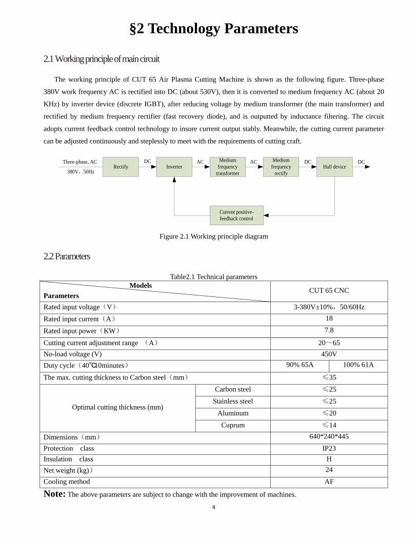
2.1 Working principle of main circuit
The working principle of CUT 65 Air Plasma Cutting Machine is shown as the following figure. Three-phase
380V work frequency AC is rectified into DC (about 530V), then it is converted to medium frequency AC (about 20
KHz) by inverter device (discrete IGBT), after reducing voltage by medium transformer (the main transformer) and
rectified by medium frequency rectifier (fast recovery diode), and is outputted by inductance filtering. The circuit
adopts current feedback control technology to insure current output stably. Meanwhile, the cutting current parameter
can be adjusted continuously and steplessly to meet with the requirements of cutting craft.
Rectify InverterMedium
frequency transformer
Medium frequency
rectifyHall device
Current positive-feedback control
Three-phase, AC DC AC DC
380V,50Hz
AC DC
Figure 2.1 Working principle diagram
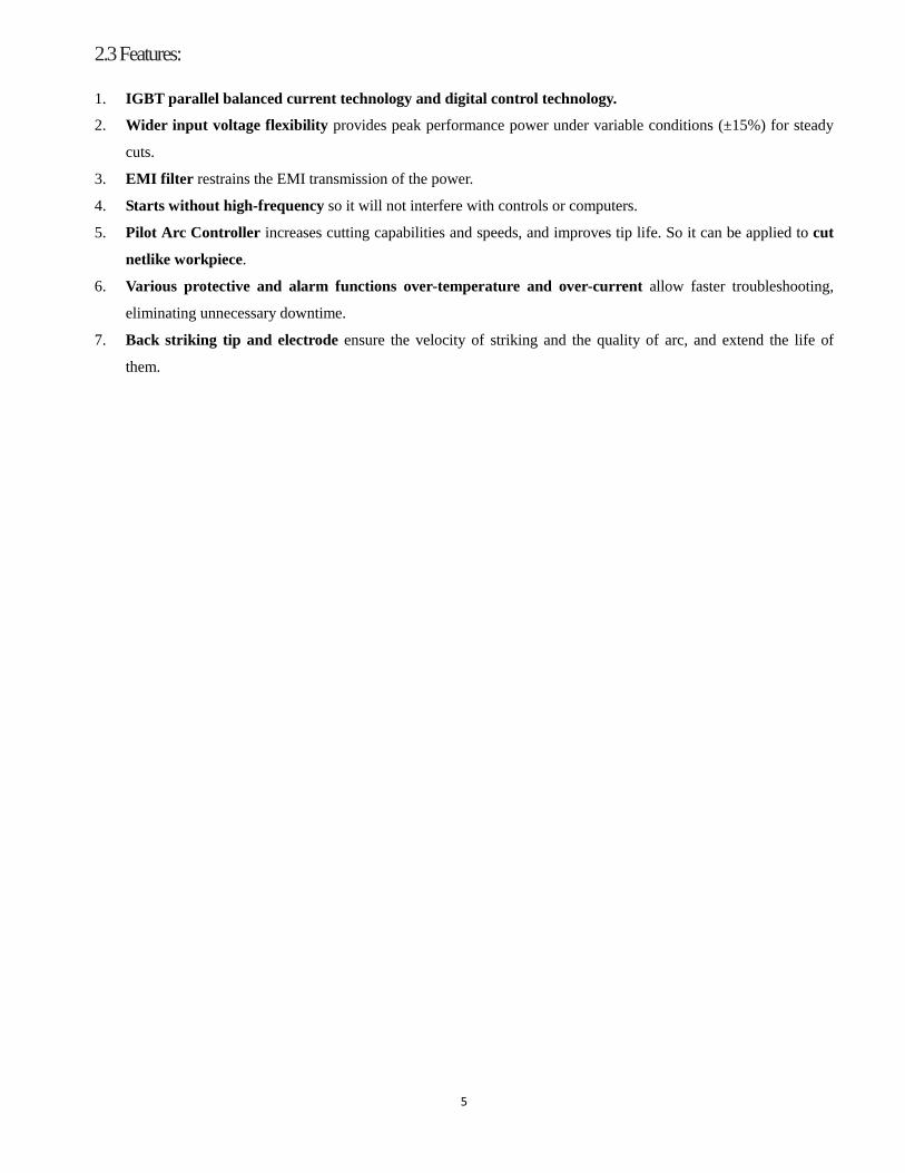
2.2 Parameters
Table2.1 Technical parameters Models
Parameters CUT 65 CNC
Rated input voltage(V) 3-380V±10%,50/60Hz
Rated input current(A) 18
Rated input power(KW) 7.8
Cutting current adjustment range (A) 20~65 No-load voltage (V) 450V Duty cycle(40℃ 10minutes) 90% 65A 100% 61A
The max. cutting thickness to Carbon steel(mm) ≤35
Optimal cutting thickness (mm)
Carbon steel ≤25
Stainless steel ≤25
Aluminum ≤20
Cuprum ≤14
Dimensions(mm) 640*240*445
Protection class IP23 Insulation class H Net weight (kg)) 24
Cooling method AF
Note: The above parameters are subject to change with the improvement of machines.
5
2.3 Features:
1. IGBT parallel balanced current technology and digital control technology.
2. Wider input voltage flexibility provides peak performance power under variable conditions (±15%) for steady
cuts.
3. EMI filter restrains the EMI transmission of the power.
4. Starts without high-frequency so it will not interfere with controls or computers.
5. Pilot Arc Controller increases cutting capabilities and speeds, and improves tip life. So it can be applied to cut
netlike workpiece.
6. Various protective and alarm functions over-temperature and over-current allow faster troubleshooting,
eliminating unnecessary downtime.
7. Back striking tip and electrode ensure the velocity of striking and the quality of arc, and extend the life of
them.
6
§3 Installation 3. 1 Unpacking
Use the packing lists to identify and account for each item.
1. Inspect each item for possible shipping damage. If damage is evident, contact your distributor and / or shipping
company before proceeding with the installation.
2. When using forklift, its arm length must be long enough to reach the outside so as to ensure lifting safely.
3. The movement may bring the potential danger or substantive hazard, so please make sure that the machine is on
the safe position before using.
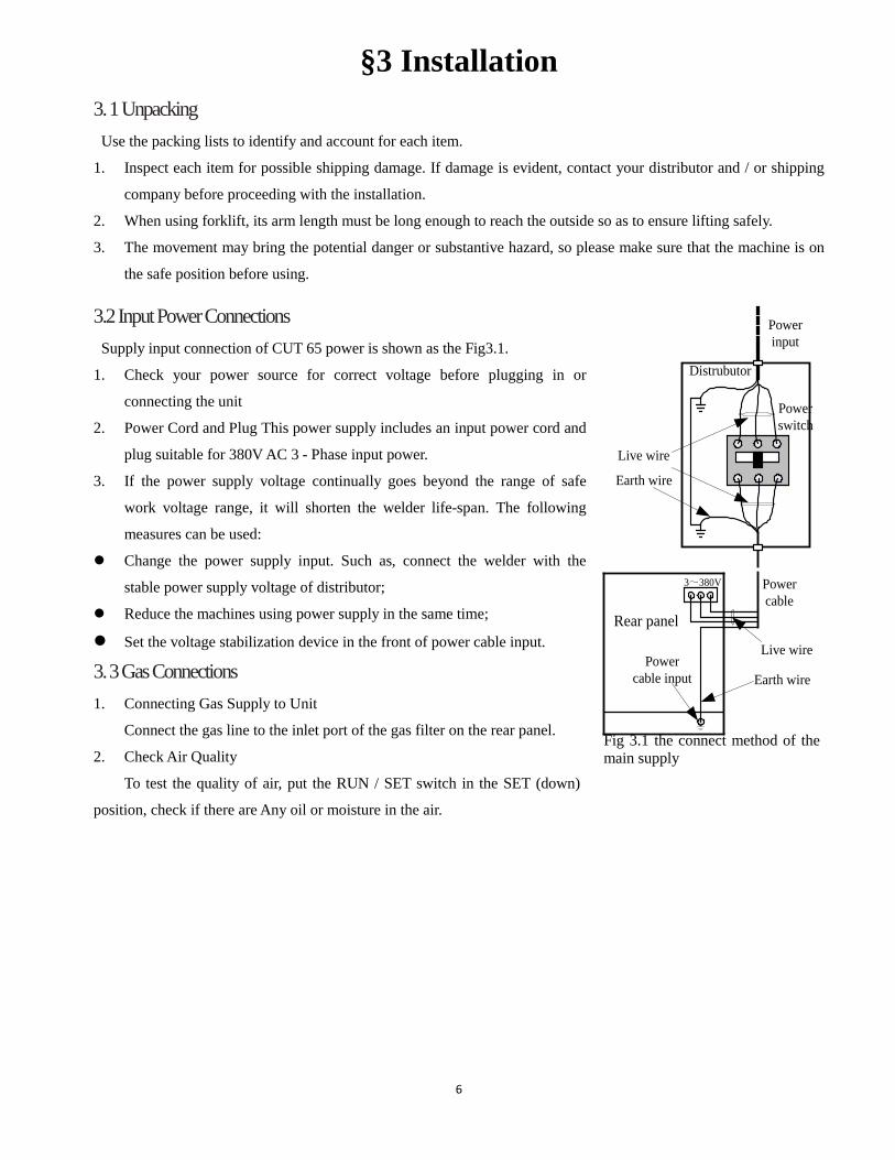
3.2 Input Power Connections Supply input connection of CUT 65 power is shown as the Fig3.1.
1. Check your power source for correct voltage before plugging in or
connecting the unit
2. Power Cord and Plug This power supply includes an input power cord and
plug suitable for 380V AC 3 - Phase input power.
3. If the power supply voltage continually goes beyond the range of safe
work voltage range, it will shorten the welder life-span. The following
measures can be used:
Change the power supply input. Such as, connect the welder with the
stable power supply voltage of distributor;
Reduce the machines using power supply in the same time;
Set the voltage stabilization device in the front of power cable input.
3. 3 Gas Connections 1. Connecting Gas Supply to Unit
Connect the gas line to the inlet port of the gas filter on the rear panel.
2. Check Air Quality
To test the quality of air, put the RUN / SET switch in the SET (down)
position, check if there are Any oil or moisture in the air.
Live wire
Earth wire
3~380V Power cable
Rear panel
Distrubutor
Earth wire
Live wire
Power input
Power switch
Power cable input
Fig 3.1 the connect method of the main supply
7
§4 Operation
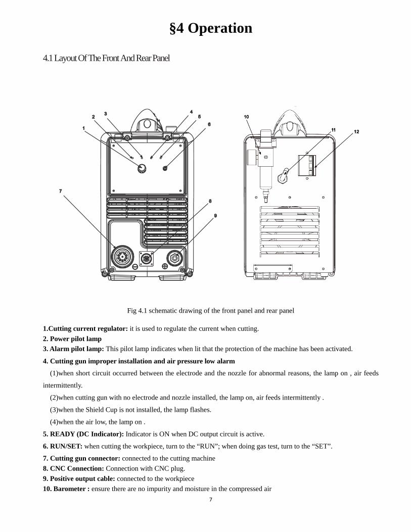
4.1 Layout Of The Front And Rear Panel
Fig 4.1 schematic drawing of the front panel and rear panel
1.Cutting current regulator: it is used to regulate the current when cutting. 2. Power pilot lamp 3. Alarm pilot lamp: This pilot lamp indicates when lit that the protection of the machine has been activated.
4. Cutting gun improper installation and air pressure low alarm
(1)when short circuit occurred between the electrode and the nozzle for abnormal reasons, the lamp on , air feeds
intermittently.
(2)when cutting gun with no electrode and nozzle installed, the lamp on, air feeds intermittently .
(3)when the Shield Cup is not installed, the lamp flashes.
(4)when the air low, the lamp on .
5. READY (DC Indicator): Indicator is ON when DC output circuit is active.
6. RUN/SET: when cutting the workpiece, turn to the “RUN”; when doing gas test, turn to the “SET”.
7. Cutting gun connector: connected to the cutting machine 8. CNC Connection: Connection with CNC plug. 9. Positive output cable: connected to the workpiece 10. Barometer : ensure there are no impurity and moisture in the compressed air
8
11. Mains cable: Connected to the appreciate power supply
12. Power switch: turn on or off the power source
4.2 Cutting Preparation
1) Tightly connect the power cable to electrical socket outlet (the input voltage, refer to the section 2 technology
parameters)
2) Tonnect the air pipe to the air supply equipment, the earth cable to the workpiece
3) Turn on the power switch ,the power source lamp on.
4) Turn the RUN/SET switch to SET position, the air flow, then regulate the air pressure to 3.5-6bar
5) Turn the RUN/SET switch to RUN position, regulate the current after the flow stops.
6) Now all the preparation done .
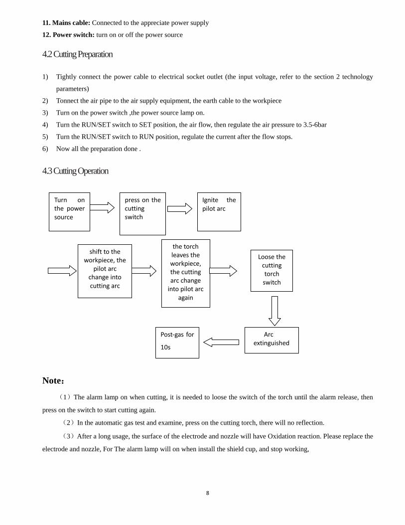
4.3 Cutting Operation
Note:
(1)The alarm lamp on when cutting, it is needed to loose the switch of the torch until the alarm release, then
press on the switch to start cutting again.
(2)In the automatic gas test and examine, press on the cutting torch, there will no reflection.
(3)After a long usage, the surface of the electrode and nozzle will have Oxidation reaction. Please replace the
electrode and nozzle, For The alarm lamp will on when install the shield cup, and stop working,
Turn on the power source
Loose the cutting torch
switch
the torch leaves the workpiece, the cutting arc change
into pilot arc again
press on the cutting switch
Ignite the pilot arc
Post-gas for
10s
shift to the workpiece, the
pilot arc change into cutting arc
Arc extinguished

9
§5 Maintenance
5.1 Cutting gun maintenance
Warning : 1. Check the consumable parts for damage, if worn, replace it.
2. Turn off the power source before check or remove cutting gun parts
Note: When operating the torch in a normal condition, a small amount of gas vents through the gap between the shield
cup and the torch handle, Do not attempt to over tighten the shield cup as irreparable damage to internal components
may result.
10
5.2 Troubleshooting Principle
WARNING
There are extremely dangerous voltage and power levels present inside this unit. Do not attempt to diagnose or
repair unless you have had training in power electronics measurement and troubleshooting techniques.
A. Power lamp and temperature lamp on.
1. Air flow blocked, check for blocked air flow around the unit and correct condition.
2. Fan blocked, check and correct condition.
3. Unit is overheated, let unit cool down for at least 5 minutes. Make sure the unit has not been operated beyond
Duty Cycle limit, refer to technology parameters in Section 2.
4. Faulty components in unit, return for repair or have qualified technician repair per Service Manual.
B. Torch fails to ignite the arc when torch switch is activated
1. System is in SET mode,change to RUN mode.
2. Faulty torch parts, inspect torch parts and replace if necessary.
3. Gas pressure too high or too low, adjust to proper pressure.
4. Faulty components in unit, return for repair or have qualified technician repair per Service Manual.
C. No cutting output; Torch activated, power source on; Gas flows; Fan operates
1. Torch not properly connected to power supply, check that torch leads are properly connected to
power supply.
2. Work cable not connected to work piece, or connection is poor, make sure that work cable has a
proper connection to a clean, dry area of the workpiece.
3. Faulty components in unit, return for repair or have qualified technician repair per Service Manual.
4. Faulty Torch, return for repair or have qualified technician repair.
D. Low cutting output
1. Incorrect setting of CURRENT (A) control, check and adjust to proper setting.
2. Faulty components in unit, return for repair or have qualified technician repair.
E. Difficult Starting
1. Worn torch parts (consumables), shut off input power. Remove and inspect torch shield cup, tip and
electrode. Replace electrode or tip if worn; replace shield cup if excessive spatter adheres to it.

11
F. Arc shuts off during operation; arc will not restart when torch switch is activated.
1. Power Supply is overheated, let unit cool down for at least 5 minutes. Make sure the unit has not
been operated beyond Duty Cycle limit. Refer to Section 2 for duty cycle specifications.
2. Gas pressure too low, check source for at least 4bar/60psi; adjust as needed. It is need to open the
machine cover.
3 Torch consumables worn, check torch shield cup, tip, starter element, and electrode; replace asneeded.
4. Faulty components in unit:, return for repair or have qualified technician repair per Service Manual.
G. No gas flow; the power lamp on; Fan operates
1. Gas not connected or pressure too low, check gas connections. Adjust gas pressure to proper settin
H. Torch cuts but low quality
1. Current (A) control set too low, increase current setting.
2. Torch is being moved too fast across workpiece, reduce cutting speed.
3. Excessive oil or moisture in torch, hold torch 1/8 inch (3 mm) from clean surface while purging and
observe oil or moisture buildup (do not activate torch). If there are contaminants in the gas, additional
filtering may be needed.
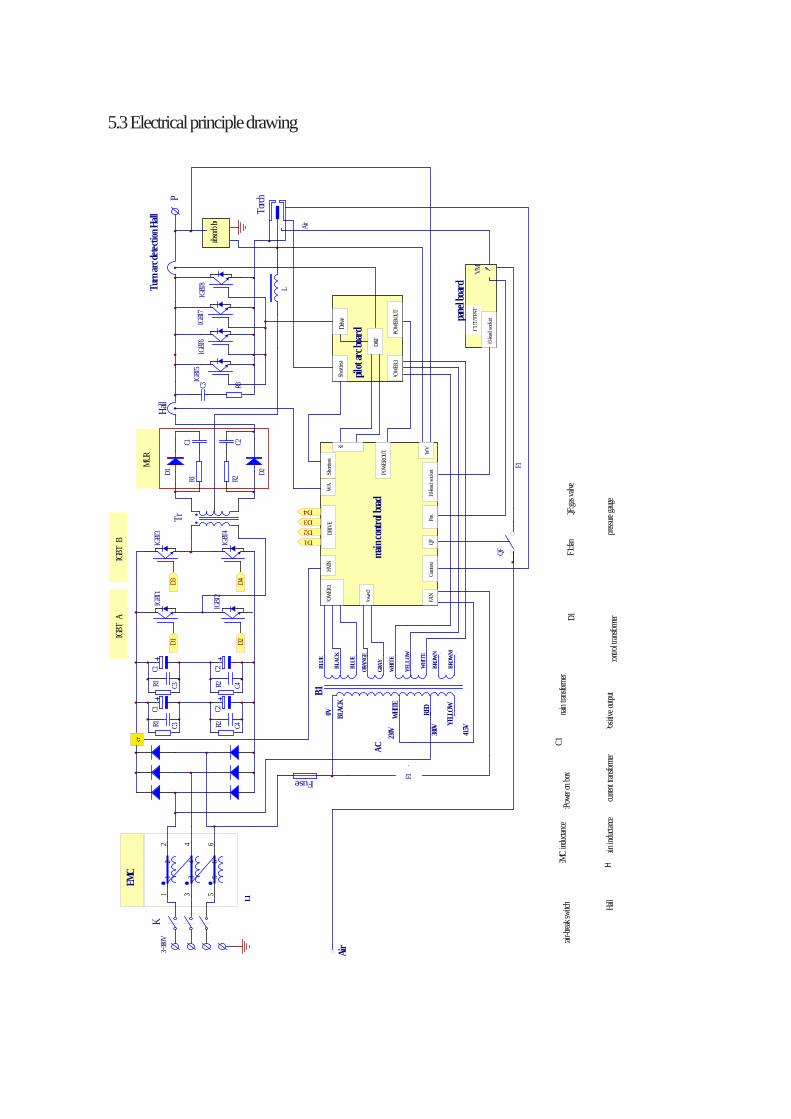
5.3 Electrical principle drawing
3~380
VR1 R2
C3 R3
absorb
bo
POWE
R1
Powe
r2
&T
WV
10-lea
d sock
et
10-lea
d sock
et
D&T
POWE
R3PO
WERO
UT
Short
test
F1
P
DRIV
E
IGBT
A
MUR
ST
HVIN
K:air-b
reak s
witch
T:Pow
er on
boxC1
EM
C ind
uctanc
ema
in tran
sform
erD1
Hall
H
ma
in ind
uctanc
e2:c
urrent
transf
ormer
Positi
ve out
putcon
trol tr
ansfor
mer
F1:fan
Hall
Tr
Torch
K
Fuse
IGBT
5
L
D2D1
IGBT
7
main
contr
ol boa
d
pilot
arc bo
ard D
rive
Short
test
POWE
ROUT
WA
D1 D2
R1 R2
C1 C2
C3 C4
C2C1
panel
board
AC
380V
FAN
11
22
33
44
55
66
L1
EMC
Turn
arc d
etecti
on H
all
QF
Air
QFGu
ntest
VM
F1
Pre. QF
:gas v
alve
pressu
re gaug
e
CUT/
TEST
Air
YELL
OW
B1
YELL
OW
WHI
TE
WHI
TE
GRAY
ORAN
GE
BROW
M
BROW
N
BLUE
BLAC
K
BLUE
WHI
TE
BLAC
K0V RE
D
415V
230V
R1 R2C3 C4
C2C1
D1 D2
IGBT
1
IGBT
2
D3 D4
IGBT
3
IGBT
4
D3D4
IGBT
6IG
BT8
IGBT
B