current sensing chip resistors - yageo sens… · 3 current sensing chip resistors introduction...
TRANSCRIPT

ww
w.y
ageo
.co
m
Current SensingChip Resistors

2
About YageoFounded in 1977, the Yageo Corporation has become a world-class provider of passive component services with capabilities on a global scale, including production and sales facilities in Asia, Europe and the Americas.
Yageo currently ranks as the world No.1 in chip-resistors, No. 3 in MLCCs and No. 4 in ferrite products, with a strong global presence: 21 sales offices in 15 countries, 9 production sites, 8 JIT logistic hubs, and 2 R&D centers worldwide. Ferroxcube and Vitrohm, who produce ferrites and leaded resistors, are also a part of the Yageo group.
We support our customers with extensive literature including datasheets, brochures and application notes, which are also available electronically on our website at: www.yageo.com
Table of Contents
Introduction .............................................................3
Current-Sensing Circuit Applications .........4
Market Applications .............................................6
Product Portfolio ...................................................7
Product Selection Tables ................................ 10

3
Current Sensing C
hip Resistors
Intro
du
ction
IntroductionLow Resistance, High Power for Current Sensing ApplicationsCurrent measurement is very important in power and instrumentation systems for circuit control, protection, monitoring, and performance enhancement. Engineers in power supply and battery circuit designs need to consider a give-and-take strategy between low resistance values to minimize power losses and sufficient voltage supplies to avoid noises generated from the environments or particularly in switch mode power supplies.
Yageo’s current-sensing chip resistors are also fully compatible with today’s high volume pick-and-place assembly systems. As such, they offer attractive, cost-effective solutions to designers of low voltage power supplies and battery management systems. Featuring a comprehensive resistance range of 0.5 milli-ohms to 1 ohm (low-ohmic), and available from 0.05 to 5 watts, they are not only applicable to battery packs, power supplies and converters, but also suitable for use in diverse power control circuits of tablets, notebook computers and hard disks.
Yageo now offers three types of surface-mount (SMT) current-sensing chip resistors based on thick film, metal foil, and metal plate technologies, with scalable product portfolios to meet the various demands of customers and their applications.
Main Features of Yageo’s Current-Sensing Chip Resistors• Lowresistancevaluefrom1mΩto20mΩforminimizingpowerlosses.
• High power-rating from 0.05 to 5 watts.
• Tight tolerance within 2% to exhibit actual current via voltage reading.
• Low TCR to avoid measurement distortions. TCR ranges from 50 to 100ppm/ºC for metal and 100 to 1500ppm/ºC for thick film current sensors.
• Scalable off-the-shelf products in standard case sizes.
• Compatibility with surface-mount assembly process.
• RoHS/REACH-compliant & Halogen-free.
The low temperature coefficient of resistance (TCR) of Yageo's current-sensing chip resistors minimizes the resistance change caused by self-heating and high temperature environments.
Thermal electromotive force (EMF) is also an important consideration. Thermal EMF is an important parameter of the metal foil series of battery management circuits, and of current-sensor resistors. Thermal electromotive force (EMF) of an Mn-Cu alloy is especially optimal with low EMF below µ0.03 uV/oC.
4
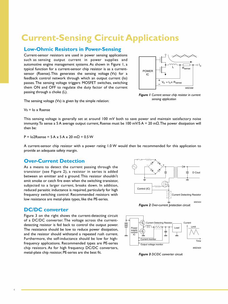
Low-Ohmic Resistors in Power-SensingCurrent-sensor resistors are used in power sensing applications such as sensing output current in power supplies and automotive engine management systems. As shown in Figure 1, a typical function for a current-sensor chip resistor is as a current-sensor (Rsense). This generates the sensing voltage (Vs) for a feedback control network through which an output current (Io) passes. The sensing voltage triggers MOSFET switches, switching them ON and OFF to regulate the duty factor of the current passing through a choke (L).
The sensing voltage (Vs) is given by the simple relation:
Vs = Io x Rsense
This sensing voltage is generally set at around 100 mV both to save power and maintain satisfactory noise immunity.Tosensea5Aaverageoutputcurrent,Rsensemustbe100mV/5A=20mΩ.Thepowerdissipationwillthen be:
P=Io2Rsense=5Ax5Ax20mΩ=0.5W
A current-sensor chip resistor with a power rating 1.0 W would then be recommended for this application to provide an adequate safety margin.
Over-Current DetectionAs a means to detect the current passing through the transistor (see Figure 2), a resistor in series is added between an emitter and a ground. This resistor shouldn't emit smoke or catch fire even when the switching transistor, subjected to a larger current, breaks down. In addition, reduced parasitic inductance is required, particularly for high frequency switching control. Recommended resistors with low resistance are metal-plate types, like the PE-series.
DC/DC converterFigure 3 on the right shows the current-detecting circuit of a DC/DC converter. The voltage across the current-detecting resistor is fed back to control the output power. The resistance should be low to reduce power dissipation, and the resistor should withstand a repeated rush current. Furthermore, the self-inductance should be low for high-frequency applications. Recommended types are PE-series chip resistors. As for high frequency DC/DC converters, metal-plate chip resistor, PE-series are the best fit.
Figure 1 Current sensor chip resistor in current sensing application
Figure 2 Over-current protection circuit
Figure 3 DC/DC converter circuit
Current-Sensing Circuit Applications
5
Current Sensing C
hip Resistors
Intro
du
ction
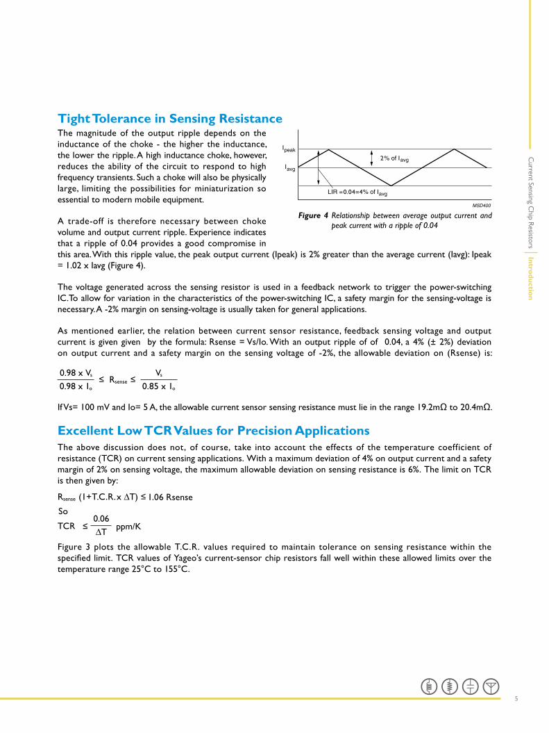
Tight Tolerance in Sensing ResistanceThe magnitude of the output ripple depends on the inductance of the choke - the higher the inductance, the lower the ripple. A high inductance choke, however, reduces the ability of the circuit to respond to high frequency transients. Such a choke will also be physically large, limiting the possibilities for miniaturization so essential to modern mobile equipment.
A trade-off is therefore necessary between choke volume and output current ripple. Experience indicates that a ripple of 0.04 provides a good compromise in this area. With this ripple value, the peak output current (Ipeak) is 2% greater than the average current (Iavg): Ipeak = 1.02 x Iavg (Figure 4).
The voltage generated across the sensing resistor is used in a feedback network to trigger the power-switching IC.To allow for variation in the characteristics of the power-switching IC, a safety margin for the sensing-voltage is necessary. A -2% margin on sensing-voltage is usually taken for general applications.
As mentioned earlier, the relation between current sensor resistance, feedback sensing voltage and output current is given given by the formula: Rsense = Vs/Io. With an output ripple of of 0.04, a 4% (± 2%) deviation on output current and a safety margin on the sensing voltage of -2%, the allowable deviation on (Rsense) is:
0.98 x Vs Vs
0.98 x 1o 0.85 x 1o
IfVs=100mVandIo=5A,theallowablecurrentsensorsensingresistancemustlieintherange19.2mΩto20.4mΩ.
Excellent Low TCR Values for Precision ApplicationsThe above discussion does not, of course, take into account the effects of the temperature coefficient of resistance (TCR) on current sensing applications. With a maximum deviation of 4% on output current and a safety margin of 2% on sensing voltage, the maximum allowable deviation on sensing resistance is 6%. The limit on TCR is then given by:
T.C.R.
TCR0.06
1.06 Rsense
So
Figure 3 plots the allowable T.C.R. values required to maintain tolerance on sensing resistance within the specifiedlimit.TCRvaluesofYageo’scurrent-sensorchipresistorsfallwellwithintheseallowedlimitsoverthetemperature range 25°C to 155°C.
Figure 4 Relationship between average output current and peak current with a ripple of 0.04
2
0.04=4
6
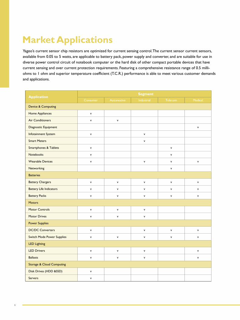
Market ApplicationsYageo’s current sensor chip resistors are optimized for current sensing control. The current sensor current sensors, available from 0.05 to 5 watts, are applicable to battery pack, power supply and converter, and are suitable for use in diverse power control circuit of notebook computer or the hard disk of other compact portable devices that have current sensing and over current protection requirements. Featuring a comprehensive resistance range of 0.5 milli-ohms to 1 ohm and superior temperature coefficient (T.C.R.) performance is able to meet various customer demands and applications.
ApplicationSegment
Consumer Automotive Industrial Telecom Medical
Device & Computing
Home Appliances v
Air Conditioners v v
Diagnostic Equipment v
Infotainment System v v
Smart Meters v
Smartphones & Tablets v v
Notebooks v v
Wearable Devices v v v v
Networking v
Batteries
Battery Chargers v v v v v
Battery Life Indicators v v v v v
Battery Packs v v v v v
Motors
Motor Controls v v v
Motor Drives v v v
Power Supplies
DC/DC Converters v v v v
Switch Mode Power Supplies v v v v v
LED Lighting
LED Drivers v v v v
Ballasts v v v v
Storage & Cloud Computing
Disk Drives (HDD &SSD) v
Servers v

7
Current Sensing C
hip Resistors
Thick Film Current-Sensing Chip Resistors (RL & PT Series)Based on thick film technology, these products exhibit far low parasitic inductance than wirewound and leaded counter parts. Yageo’s thick film RL/PT low-ohmic current sensing chip resistors is low cost, capable of providing low TCR down to ±75ppm/°C, resistance value downto50mΩwithpowerupto2wattsofpowerdissipation.
Metal Foil Current-Sensing Chip Resistors (PE & PF Series)Metal foil current-sensing resistors made of Mn-Cu alloy are developed with substrates to provide a better thermal dissipation and with a wider resistancerangeupto300mΩ.MetalfoilPEseriesfeature low EMF below conditions of temperature changes. µ0.03 uV/ºC is more likely to endure harsh conditions. In the metal foil type, TCR ranges from 50 to 100ppm/ºC, power rates up to 3W, andresistancevalueisavailableaslowas0.5mΩ.
Metal Plate Current-Sensing Chip Resistors (PA & PR Series)A related simple construction without multiple cuts, metal plate current-sensing resistors provide low TCR down to ±25ppm/°C, high power rating up to 3W, high frequency performance and low resistancedownto0.5mΩ.
Wide Terminal Current-Sensing Chip Resistors Using the wider side as connection in the mounting plate, wide terminal current-sensing chip resistors strengthen solder joints, holding reliably to achieve higher power rating needs. With an ideal structure to suppress heat generation, wide terminal type current- sensors save space, and reduce resistor numbers in high-density circuit board designs.
Four-Terminal, Current-Sensing Chip Resistors Design of accurate measurement circuitry, lower power consumption, higher accuracy, and smaller space requirements are important features for electronic control units. To minimize power losses, a large current across the (Rsense) resistor needs to be measured, and high-side, current-sense amplifier ICs have to monitor the current accurately. Four-terminal, current-sensing resistors separating current-carry from voltage-sensing terminals are able to improve voltage and current measurement accuracy from the ideal Kelvin configuration. They also improve interference and thermoelectric effects at higher applied power.
metal substrate
end termination
protective coat
H
I2
Market A
pp
lication
s / Pro
du
ct Po
rtfolio
Product Portfoliomarking layer
overcoat
protective coat
resistive layer
inner electrode
inner electrodeceramic substrate
termination (Ni / matte tin)
H
I2
marking layer
protective coat
end termination
inner electrode
protective coat
ceramic substrateresistive layer (metal foil)
H
I2
marking layerprotective coat
resistive layer
inner electrode
termination (Ni/matte tin)
ceramic substrate
Cross section of RL / PT series
Cross section of PE / PF series
Cross section of PA / PR series
Cross section of wide terminal series
8
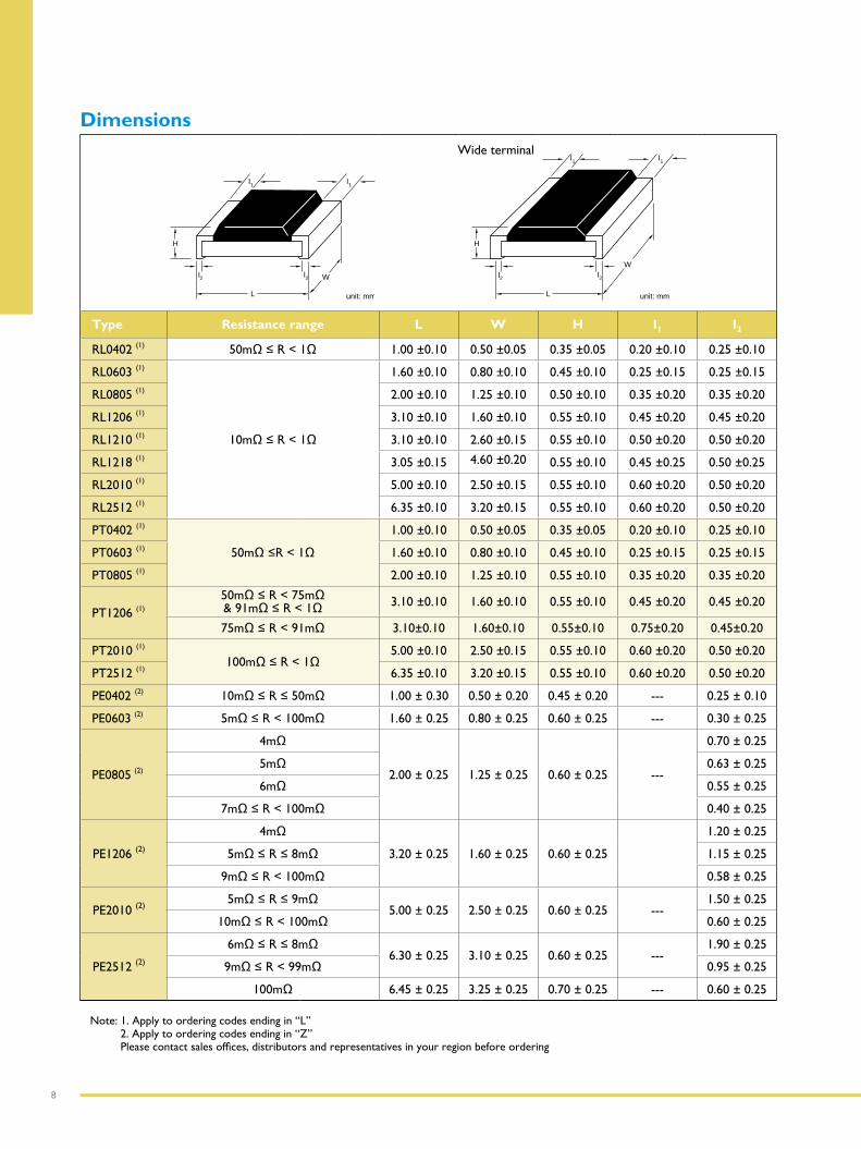
Dimensions
W
unit: mm
I2
I2
I1
I1
L
H
Wide terminal
W
unit: mm
I2
I2
I1
I1
L
H
Type Resistance range L W H I1 I2
RL0402 (1) 50mΩ≤R<1Ω 1.00 ±0.10 0.50 ±0.05 0.35 ±0.05 0.20 ±0.10 0.25 ±0.10
RL0603 (1)
10mΩ≤R<1Ω
1.60 ±0.10 0.80 ±0.10 0.45 ±0.10 0.25 ±0.15 0.25 ±0.15
RL0805 (1) 2.00 ±0.10 1.25 ±0.10 0.50 ±0.10 0.35 ±0.20 0.35 ±0.20
RL1206 (1) 3.10 ±0.10 1.60 ±0.10 0.55 ±0.10 0.45 ±0.20 0.45 ±0.20
RL1210 (1) 3.10 ±0.10 2.60 ±0.15 0.55 ±0.10 0.50 ±0.20 0.50 ±0.20
RL1218 (1) 3.05 ±0.15 4.60 ±0.20 0.55 ±0.10 0.45 ±0.25 0.50 ±0.25
RL2010 (1) 5.00 ±0.10 2.50 ±0.15 0.55 ±0.10 0.60 ±0.20 0.50 ±0.20
RL2512 (1) 6.35 ±0.10 3.20 ±0.15 0.55 ±0.10 0.60 ±0.20 0.50 ±0.20
PT0402 (1)
50mΩ≤R<1Ω
1.00 ±0.10 0.50 ±0.05 0.35 ±0.05 0.20 ±0.10 0.25 ±0.10
PT0603 (1) 1.60 ±0.10 0.80 ±0.10 0.45 ±0.10 0.25 ±0.15 0.25 ±0.15
PT0805 (1) 2.00 ±0.10 1.25 ±0.10 0.55 ±0.10 0.35 ±0.20 0.35 ±0.20
PT1206 (1)
50mΩ≤R<75mΩ&91mΩ≤R<1Ω 3.10 ±0.10 1.60 ±0.10 0.55 ±0.10 0.45 ±0.20 0.45 ±0.20
75mΩ≤R<91mΩ 3.10±0.10 1.60±0.10 0.55±0.10 0.75±0.20 0.45±0.20
PT2010 (1)
100mΩ≤R<1Ω5.00 ±0.10 2.50 ±0.15 0.55 ±0.10 0.60 ±0.20 0.50 ±0.20
PT2512 (1) 6.35 ±0.10 3.20 ±0.15 0.55 ±0.10 0.60 ±0.20 0.50 ±0.20
PE0402 (2) 10mΩ≤R≤50mΩ 1.00 ± 0.30 0.50 ± 0.20 0.45 ± 0.20 --- 0.25 ± 0.10
PE0603 (2) 5mΩ≤R<100mΩ 1.60 ± 0.25 0.80 ± 0.25 0.60 ± 0.25 --- 0.30 ± 0.25
PE0805 (2)
4mΩ
2.00 ± 0.25 1.25 ± 0.25 0.60 ± 0.25 ---
0.70 ± 0.25
5mΩ 0.63 ± 0.25
6mΩ 0.55 ± 0.25
7mΩ≤R<100mΩ 0.40 ± 0.25
PE1206 (2)
4mΩ
3.20 ± 0.25 1.60 ± 0.25 0.60 ± 0.25
1.20 ± 0.25
5mΩ≤R≤8mΩ 1.15 ± 0.25
9mΩ≤R<100mΩ 0.58 ± 0.25
PE2010 (2)5mΩ≤R≤9mΩ
5.00 ± 0.25 2.50 ± 0.25 0.60 ± 0.25 ---1.50 ± 0.25
10mΩ≤R<100mΩ 0.60 ± 0.25
PE2512 (2)
6mΩ≤R≤8mΩ6.30 ± 0.25 3.10 ± 0.25 0.60 ± 0.25 ---
1.90 ± 0.25
9mΩ≤R<99mΩ 0.95 ± 0.25
100mΩ 6.45 ± 0.25 3.25 ± 0.25 0.70 ± 0.25 --- 0.60 ± 0.25
Note: 1. Apply to ordering codes ending in “L” 2. Apply to ordering codes ending in “Z” Pleasecontactsalesoffices,distributorsandrepresentativesinyourregionbeforeordering
9
Current Sensing C
hip Resistors
Pro
du
ct Po
rtfolio
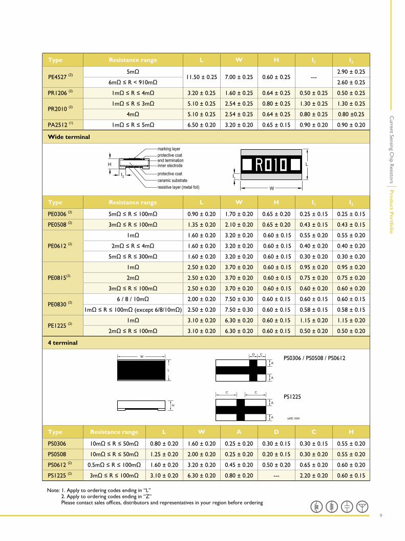
Type Resistance range L W H I1 I2
PE4527 (2)5mΩ
11.50 ± 0.25 7.00 ± 0.25 0.60 ± 0.25 ---2.90 ± 0.25
6mΩ≤R<910mΩ 2.60 ± 0.25
PR1206 (2) 1mΩ≤R≤4mΩ 3.20 ± 0.25 1.60 ± 0.25 0.64 ± 0.25 0.50 ± 0.25 0.50 ± 0.25
PR2010 (2)1mΩ≤R≤3mΩ 5.10 ± 0.25 2.54 ± 0.25 0.80 ± 0.25 1.30 ± 0.25 1.30 ± 0.25
4mΩ 5.10 ± 0.25 2.54 ± 0.25 0.64 ± 0.25 0.80 ± 0.25 0.80 ±0.25
PA2512 (1) 1mΩ≤R≤5mΩ 6.50 ± 0.20 3.20 ± 0.20 0.65 ± 0.15 0.90 ± 0.20 0.90 ± 0.20
Wide terminal
Type Resistance range L W H I1 I2
PE0306 (2) 5mΩ≤R≤100mΩ 0.90 ± 0.20 1.70 ± 0.20 0.65 ± 0.20 0.25 ± 0.15 0.25 ± 0.15
PE0508 (2) 3mΩ≤R≤100mΩ 1.35 ± 0.20 2.10 ± 0.20 0.65 ± 0.20 0.43 ± 0.15 0.43 ± 0.15
PE0612 (2)
1mΩ 1.60 ± 0.20 3.20 ± 0.20 0.60 ± 0.15 0.55 ± 0.20 0.55 ± 0.20
2mΩ≤R≤4mΩ 1.60 ± 0.20 3.20 ± 0.20 0.60 ± 0.15 0.40 ± 0.20 0.40 ± 0.20
5mΩ≤R≤300mΩ 1.60 ± 0.20 3.20 ± 0.20 0.60 ± 0.15 0.30 ± 0.20 0.30 ± 0.20
PE0815(2)
1mΩ 2.50 ± 0.20 3.70 ± 0.20 0.60 ± 0.15 0.95 ± 0.20 0.95 ± 0.20
2mΩ 2.50 ± 0.20 3.70 ± 0.20 0.60 ± 0.15 0.75 ± 0.20 0.75 ± 0.20
3mΩ≤R≤100mΩ 2.50 ± 0.20 3.70 ± 0.20 0.60 ± 0.15 0.60 ± 0.20 0.60 ± 0.20
PE0830 (2)6/8/10mΩ 2.00 ± 0.20 7.50 ± 0.30 0.60 ± 0.15 0.60 ± 0.15 0.60 ± 0.15
1mΩ≤R≤100mΩ(except6/8/10mΩ) 2.50 ± 0.20 7.50 ± 0.30 0.60 ± 0.15 0.58 ± 0.15 0.58 ± 0.15
PE1225 (2)1mΩ 3.10 ± 0.20 6.30 ± 0.20 0.60 ± 0.15 1.15 ± 0.20 1.15 ± 0.20
2mΩ≤R≤100mΩ 3.10 ± 0.20 6.30 ± 0.20 0.60 ± 0.15 0.50 ± 0.20 0.50 ± 0.20
4 terminal
unit: mm
W
L
D C
C
A
A
A
A
H
C
Type Resistance range L W A D C H
PS0306 10mΩ≤R≤50mΩ 0.80 ± 0.20 1.60 ± 0.20 0.25 ± 0.20 0.30 ± 0.15 0.30 ± 0.15 0.55 ± 0.20
PS0508 10mΩ≤R≤50mΩ 1.25 ± 0.20 2.00 ± 0.20 0.25 ± 0.20 0.20 ± 0.15 0.30 ± 0.20 0.55 ± 0.20
PS0612 (2) 0.5mΩ≤R≤100mΩ 1.60 ± 0.20 3.20 ± 0.20 0.45 ± 0.20 0.50 ± 0.20 0.65 ± 0.20 0.60 ± 0.20
PS1225 (2) 3mΩ≤R≤100mΩ 3.10 ± 0.20 6.30 ± 0.20 0.80 ± 0.20 --- 2.20 ± 0.20 0.60 ± 0.15
Note: 1. Apply to ordering codes ending in “L” 2. Apply to ordering codes ending in “Z” Pleasecontactsalesoffices,distributorsandrepresentativesinyourregionbeforeordering
PS0306 / PS0508 / PS0612
PS1225
10
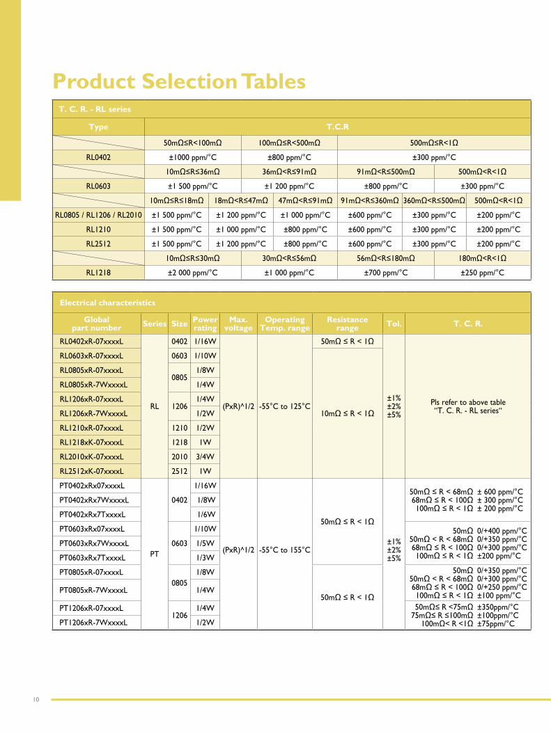
Product Selection TablesT. C. R. - RL series
Type T.C.R
50mΩ≤R<100mΩ 100mΩ≤R<500mΩ 500mΩ≤R<1Ω
RL0402 ±1000 ppm/°C ±800 ppm/°C ±300 ppm/°C
10mΩ≤R≤36mΩ 36mΩ<R≤91mΩ 91mΩ<R≤500mΩ 500mΩ<R<1Ω
RL0603 ±1 500 ppm/°C ±1 200 ppm/°C ±800 ppm/°C ±300 ppm/°C
10mΩ≤R≤18mΩ 18mΩ<R≤47mΩ 47mΩ<R≤91mΩ 91mΩ<R≤360mΩ 360mΩ<R≤500mΩ 500mΩ<R<1Ω
RL0805 / RL1206 / RL2010 ±1 500 ppm/°C ±1 200 ppm/°C ±1 000 ppm/°C ±600 ppm/°C ±300 ppm/°C ±200 ppm/°C
RL1210 ±1 500 ppm/°C ±1 000 ppm/°C ±800 ppm/°C ±600 ppm/°C ±300 ppm/°C ±200 ppm/°C
RL2512 ±1 500 ppm/°C ±1 200 ppm/°C ±800 ppm/°C ±600 ppm/°C ±300 ppm/°C ±200 ppm/°C
10mΩ≤R≤30mΩ 30mΩ<R≤56mΩ 56mΩ<R≤180mΩ 180mΩ<R<1Ω
RL1218 ±2 000 ppm/°C ±1 000 ppm/°C ±700 ppm/°C ±250 ppm/°C
Electrical characteristics
Global part number Series Size Power
rating Max.
voltage Operating
Temp. range Resistance
range Tol. T. C. R.
RL0402xR-07xxxxL
RL
0402 1/16W
(PxR)^1/2 -55°C to 125°C
50mΩ≤R<1Ω
±1% ±2% ±5%
Pls refer to above table“T. C. R. - RL series“
RL0603xR-07xxxxL 0603 1/10W
10mΩ≤R<1Ω
RL0805xR-07xxxxL 0805
1/8W
RL0805xR-7WxxxxL 1/4W
RL1206xR-07xxxxL 1206
1/4W
RL1206xR-7WxxxxL 1/2W
RL1210xR-07xxxxL 1210 1/2W
RL1218xK-07xxxxL 1218 1W
RL2010xK-07xxxxL 2010 3/4W
RL2512xK-07xxxxL 2512 1W
PT0402xRx07xxxxL
PT
0402
1/16W
(PxR)^1/2
-55°C to 155°C
50mΩ≤R<1Ω
±1% ±2% ±5%
50mΩ≤R<68mΩ68mΩ≤R<100Ω100mΩ≤R<1Ω
± 600 ppm/°C± 300 ppm/°C± 200 ppm/°C
PT0402xRx7WxxxxL 1/8W
PT0402xRx7TxxxxL 1/6W
PT0603xRx07xxxxL
0603
1/10W 50mΩ50mΩ<R<68mΩ68mΩ≤R<100Ω100mΩ≤R<1Ω
0/+400 ppm/°C0/+350 ppm/°C0/+300 ppm/°C±200 ppm/°C
PT0603xRx7WxxxxL 1/5W
PT0603xRx7TxxxxL 1/3W
PT0805xR-07xxxxL0805
1/8W
50mΩ≤R<1Ω
50mΩ50mΩ<R<68mΩ68mΩ≤R<100Ω100mΩ≤R<1Ω
0/+350 ppm/°C0/+300 ppm/°C0/+250 ppm/°C±100 ppm/°C
PT0805xR-7WxxxxL 1/4W
PT1206xR-07xxxxL1206
1/4W 50mΩ≤ R <75mΩ75mΩ≤ R ≤100mΩ
100mΩ< R <1Ω
±350ppm/°C±100ppm/°C±75ppm/°CPT1206xR-7WxxxxL 1/2W
11
Current Sensing C
hip Resistors
Pro
du
ct Selectio
n T
able
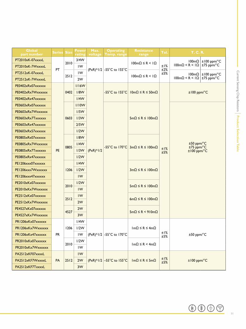
Global part number Series Size Power
rating Max.
voltage Operating
Temp. range Resistance
range Tol. T. C. R.
PT2010xK-07xxxxL
PT
20103/4W
(PxR)^1/2 -55°C to 155°C
100mΩ≤R<1Ω±1%±2% ±5%
100mΩ 100mΩ<R<1Ω
±100 ppm/°C±75 ppm/°CPT2010xK-7WxxxxL 1W
PT2512xK-07xxxxL2512
1W100mΩ≤R<1Ω 100mΩ
100mΩ<R<1Ω ±100 ppm/°C±75 ppm/°CPT2512xK-7WxxxxL 2W
PE0402xRx07xxxxxx
PE
0402
1/16W
(PxR)^1/2
-55°C to 155°C 10mΩ≤R≤50mΩ
±1%±5%
±100 ppm/°CPE0402xRx7Wxxxxxx 1/8W
PE0402xRx47xxxxxx 1/4W
PE0603xRx07xxxxxx
0603
1/10W
-55°C to 170°C
5mΩ≤R≤100mΩ
±50 ppm/°C±75 ppm/°C±100 ppm/°C
PE0603xRx7Wxxxxxx 1/5W
PE0603xRx7Txxxxxx 1/3W
PE0603xRx47xxxxxx 2/5W
PE0603xRx57xxxxxx 1/2W
PE0805xRx07xxxxxx
0805
1/8W
3mΩ≤R≤100mΩPE0805xRx7Wxxxxxx 1/4W
PE0805xRx7Txxxxxx 1/3W
PE0805xRx47xxxxxx 1/2W
PE1206xxx07xxxxxx
1206
1/4W
3mΩ≤R≤100mΩPE1206xxx7Wxxxxxx 1/2W
PE1206xxx47xxxxxx 1W
PE2010xKx07xxxxxx2010
1/2W5mΩ≤R≤100mΩ
PE2010xKx7Wxxxxxx 1W
PE2512xKx07xxxxxx2512
1W6mΩ≤R≤100mΩ
PE2512xKx7Wxxxxxx 2W
PE4527xKx07xxxxxx4527
2W5mΩ≤R<910mΩ
PE4527xKx7Wxxxxxx 3W
PR1206xKx07xxxxxx
PR
1206
1/4W
(PxR)^1/2 -55°C to 170°C
1mΩ≤R≤4mΩ±1% ±5% ±50 ppm/°C
PR1206xKx7Wxxxxxx 1/2W
PR1206xKx47xxxxxx 1W
PR2010xKx07xxxxxx2010
1/2W1mΩ≤R<4mΩ
PR2010xKx7Wxxxxxx 1W
PA2512xKF07xxxxL
PA 2512
1W
(PxR)^1/2 –55°C to 155°C 1mΩ≤R≤5mΩ ±1% ±5% ±100 ppm/°CPA2512xKF7WxxxxL 2W
PA2512xKF7TxxxxL 3W
12
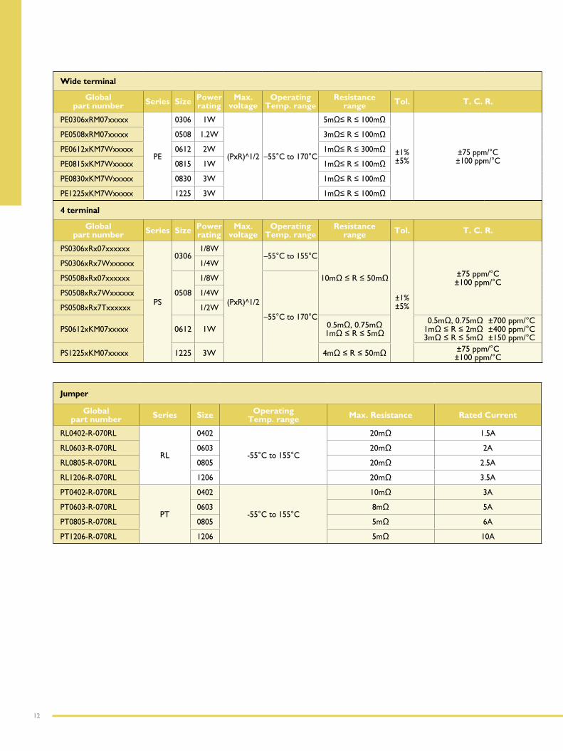
Wide terminal
Global part number Series Size Power
rating Max.
voltage Operating
Temp. range Resistance
range Tol. T. C. R.
PE0306xRM07xxxxx
PE
0306 1W
(PxR)^1/2 –55°C to 170°C
5mΩ≤R≤100mΩ
±1%±5%
±75 ppm/°C±100 ppm/°C
PE0508xRM07xxxxx 0508 1.2W 3mΩ≤R≤100mΩ
PE0612xKM7Wxxxxx 0612 2W 1mΩ≤R≤300mΩ
PE0815xKM7Wxxxxx 0815 1W 1mΩ≤R≤100mΩ
PE0830xKM7Wxxxxx 0830 3W 1mΩ≤R≤100mΩ
PE1225xKM7Wxxxxx 1225 3W 1mΩ≤R≤100mΩ
4 terminal
Global part number Series Size Power
rating Max.
voltage Operating
Temp. range Resistance
range Tol. T. C. R.
PS0306xRx07xxxxxx
PS
03061/8W
(PxR)^1/2
–55°C to 155°C
10mΩ≤R≤50mΩ
±1% ±5%
±75 ppm/°C±100 ppm/°C
PS0306xRx7Wxxxxxx 1/4W
PS0508xRx07xxxxxx
0508
1/8W
–55°C to 170°C
PS0508xRx7Wxxxxxx 1/4W
PS0508xRx7Txxxxxx 1/2W
PS0612xKM07xxxxx 0612 1W 0.5mΩ,0.75mΩ1mΩ≤R≤5mΩ
0.5mΩ,0.75mΩ1mΩ≤R≤2mΩ3mΩ≤R≤5mΩ
±700 ppm/°C ±400 ppm/°C ±150 ppm/°C
PS1225xKM07xxxxx 1225 3W 4mΩ≤R≤50mΩ ±75 ppm/°C±100 ppm/°C
Jumper
Global part number Series Size Operating
Temp. range Max. Resistance Rated Current
RL0402-R-070RL
RL
0402
-55°C to 155°C
20mΩ 1.5A
RL0603-R-070RL 0603 20mΩ 2A
RL0805-R-070RL 0805 20mΩ 2.5A
RL1206-R-070RL 1206 20mΩ 3.5A
PT0402-R-070RL
PT
0402
-55°C to 155°C
10mΩ 3A
PT0603-R-070RL 0603 8mΩ 5A
PT0805-R-070RL 0805 5mΩ 6A
PT1206-R-070RL 1206 5mΩ 10A
13
Current Sensing C
hip Resistors
Pro
du
ct Po
rtfolio
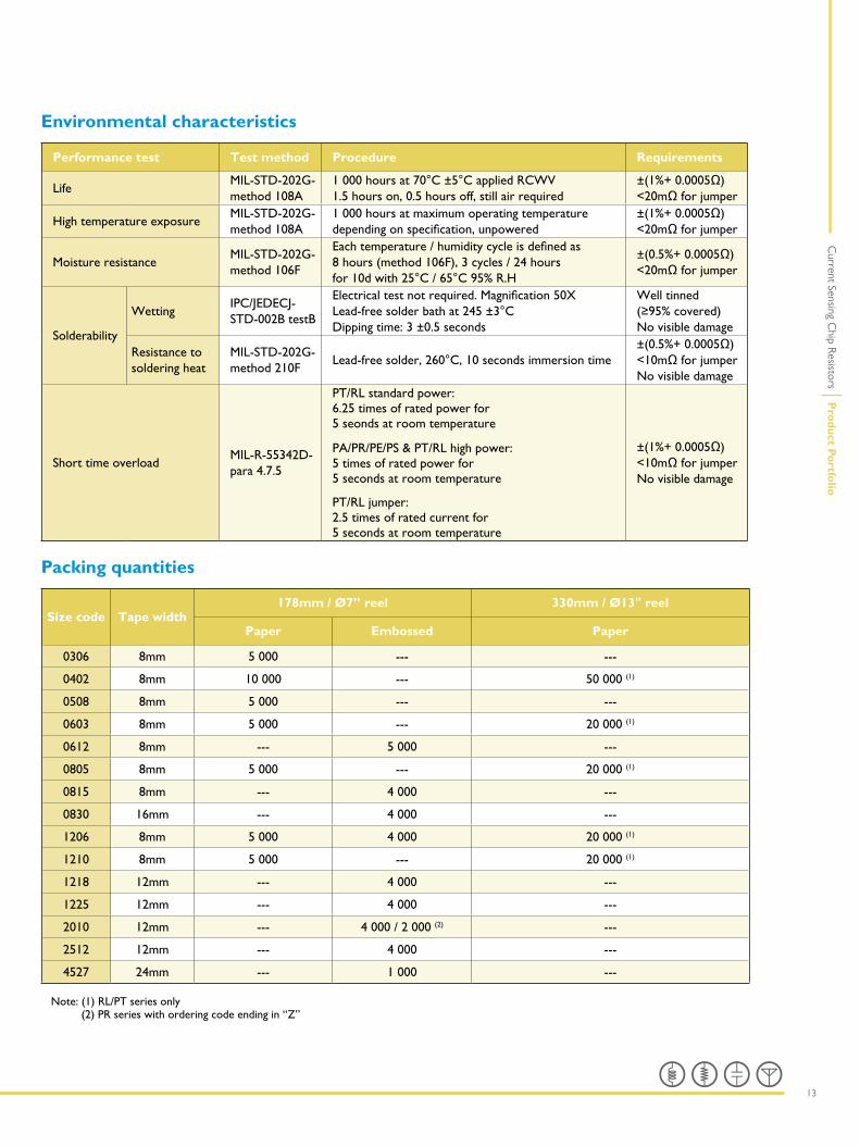
Environmental characteristics
Performance test Test method Procedure Requirements
LifeMIL-STD-202G-method 108A
1 000 hours at 70°C ±5°C applied RCWV 1.5 hours on, 0.5 hours off, still air required
±(1%+0.0005Ω) <20mΩforjumper
High temperature exposureMIL-STD-202G-method 108A
1 000 hours at maximum operating temperature dependingonspecification,unpowered
±(1%+0.0005Ω)<20mΩforjumper
Moisture resistanceMIL-STD-202G-method 106F
Eachtemperature/humiditycycleisdefinedas8 hours (method 106F), 3 cycles / 24 hours for 10d with 25°C / 65°C 95% R.H
±(0.5%+0.0005Ω)<20mΩforjumper
Solderability
WettingIPC/JEDECJ-STD-002B testB
Electricaltestnotrequired.Magnification50X Lead-free solder bath at 245 ±3°C Dipping time: 3 ±0.5 seconds
Well tinned (≥95%covered)No visible damage
Resistance to soldering heat
MIL-STD-202G-method 210F
Lead-free solder, 260°C, 10 seconds immersion time±(0.5%+0.0005Ω)<10mΩforjumperNo visible damage
Short time overloadMIL-R-55342D-para 4.7.5
PT/RL standard power:6.25 times of rated power for5 seonds at room temperature
PA/PR/PE/PS & PT/RL high power:5 times of rated power for5 seconds at room temperature
PT/RL jumper:2.5 times of rated current for5 seconds at room temperature
±(1%+0.0005Ω)<10mΩforjumperNo visible damage
Packing quantities
Size code Tape width178mm / Ø7” reel 330mm / Ø13" reel
Paper Embossed Paper
0306 8mm 5 000 --- ---
0402 8mm 10 000 --- 50 000 (1)
0508 8mm 5 000 --- ---
0603 8mm 5 000 --- 20 000 (1)
0612 8mm --- 5 000 ---
0805 8mm 5 000 --- 20 000 (1)
0815 8mm --- 4 000 ---
0830 16mm --- 4 000 ---
1206 8mm 5 000 4 000 20 000 (1)
1210 8mm 5 000 --- 20 000 (1)
1218 12mm --- 4 000 ---
1225 12mm --- 4 000 ---
2010 12mm --- 4 000 / 2 000 (2) ---
2512 12mm --- 4 000 ---
4527 24mm --- 1 000 ---
Note: (1) RL/PT series only (2) PR series with ordering code ending in “Z”
14
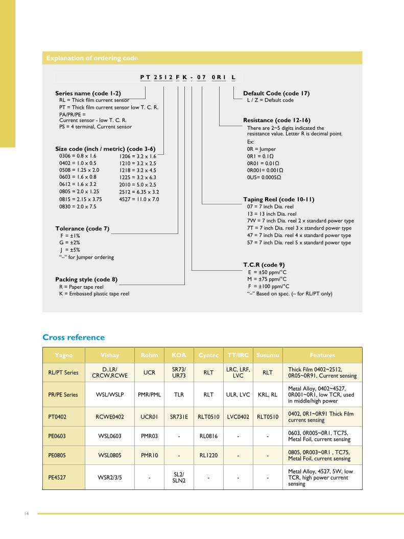
Explanation of ordering code
P T 2 5 1 2 F K - 0 7 0 R 1 L
Series name (code 1-2) Default Code (code 17)RL=Thickfilmcurrentsensor L / Z = Default codePT=ThickfilmcurrentsensorlowT.C.R. PA/PR/PE = Current sensor - low T. C. R. Resistance (code 12-16) PS = 4 terminal, Current sensor There are 2~5 digits indicated the
resistance value. Letter R is decimal point.
Ex: Size code (inch / metric) (code 3-6) 0R = Jumper
0306 = 0.8 x 1.6 1206 = 3.2 x 1.6 0R1=0.1Ω0402 = 1.0 x 0.5 1210 = 3.2 x 2.5 0R01=0.01Ω0508 = 1.25 x 2.0 1218 = 3.2 x 4.5 0R001=0.001Ω0603 = 1.6 x 0.8 1225 = 3.2 x 6.3 0U5=0.0005Ω0612 = 1.6 x 3.2 2010 = 5.0 x 2.50805 = 2.0 x 1.25 2512 = 6.35 x 3.20815 = 2.15 x 3.75 4527 = 11.0 x 7.0 Taping Reel (code 10-11) 0830 = 2.0 x 7.5 07 = 7 inch Dia. reel
13 = 13 inch Dia. reel7W = 7 inch Dia. reel 2 x standard power type
Tolerance (code 7) 7T = 7 inch Dia. reel 3 x standard power typeF = ±1% 47 = 7 inch Dia. reel 4 x standard power typeG = ±2% 57 = 7 inch Dia. reel 5 x standard power typeJ = ±5%“–” for Jumper ordering
T.C.R (code 9)E = ±50 ppm/°C
Packing style (code 8) M = ±75 ppm/°CR = Paper tape reel F = ±100 ppm/°CK = Embossed plastic tape reel “–” Based on spec. (– for RL/PT only)
Cross reference
Yageo Vishay Rohm KOA Cyntec TT/IRC Susumu Features
RL/PT Series D..LR/ CRCW,RCWE UCR SR73/
UR73 RLT LRC, LRF,LVC RLT Thick Film 0402~2512,
0R05~0R91, Current sensing
PR/PE Series WSL/WSLP PMR/PML TLR RLT ULR, LVC KRL, RLMetal Alloy, 0402~4527, 0R001~0R1, low TCR, used in middle/high power
PT0402 RCWE0402 UCR01 SR731E RLT0510 LVC0402 RLT0510 0402, 0R1~0R91 Thick Film current sensing
PE0603 WSL0603 PMR03 - RL0816 - - 0603, 0R005~0R1, TC75, Metal Foil, current sensing
PE0805 WSL0805 PMR10 - RL1220 - - 0805, 0R003~0R1 , TC75, Metal Foil, current sensing
PE4527 WSR2/3/5 - SL2/SLN2 - - -
Metal Alloy, 4527, 5W, low TCR, high power current sensing
15
Current Sensing C
hip Resistors
Exp
lanatio
n o
f ord
ering co
de / C
ross referen
ce
Customer Support & Distribution Network
We bring to the market a proven innovative tradition and a commitment to service second to none.
Yageo sales representatives are available to visit you to discuss the technical and commercial issues appropriate to your project or requirement. Customer service can initiate new orders, change orders, request air shipments or drop shipments, product samples, and generally support your business on a day to day basis.
Oursales/servicesofficesarestrategicallylocatedtoserve our customers worldwide and our internationaldistributor network improves our product availability,delivery lead time and our service anywhere in theworld.
Please see the back cover for contact details of your local Yageo organization.
We support our customers with extensive literature including datasheets, brochures and application notes, which are also available electronically on our website at:www.yageo.com
Inaddition,ourfieldapplicationengineersconstantlystrive wherever possible, to work closely with customers to aid them with design-in and provide them with the support they need to remain competitive in their markets.
Disclaimer
Allproductspecifications,statements,informationanddata (collectively, the “Information”) are subject to change without notice.
All Information given herein is believed to be accurate and reliable, but is presented without guarantee, warranty, or responsibility of any kind, expressed or implied.
Statements of suitability for certain applications are based on our knowledge of typical operating conditions for such applications, but are not intended to constitute -andwespecificallydisclaim-anywarrantyconcerningsuitabilityforaspecificcustomerapplicationoruse.This Information is intended for use only by customers who have the requisite experience and capability to determine the correct products for their application. Any technical advice inferred from this Information or otherwise provided by us with reference to the use of our products is given gratis, and we assume no obligation or liability for the advice given or results obtained.
Although we design and manufacture our products to the most stringent quality and safety standards, given the current state of the art, isolated component failures may still occur. Accordingly, customer applications which require a high degree of reliability or safety should employ suitable designs or other safeguards (such as installation of protective circuitry or redundancies) in order to ensure that the failure of an electrical component does not result in a risk of personal injury or property damage.
Although all product-related warnings, cautions and notes must be observed, the customer should not assume that all safety measures are indicated or that other measures may not be required.
Date of release: April 2014Printed in Taiwan Document order number: YL 100 00146
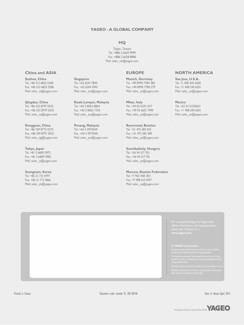
YAGEO - A GLOBAL COMPANY
For a complete listing of all Yageo sales offices,distributors,andrepresentatives,please visit "contact us" at www.yageo.com
© YAGEO CorporationAll rights are reserved. Reproduction in whole or in part is prohibited without the prior written consent of the copyright owner.
The information presented in this document does not form part of any quotation or contract, is believed to be accurate and reliable and may be changed without notice.
No liability will be accepted by the publisher for any consequence of its use.
Publication thereof does not convey nor imply any license under patent or other industrial or intellectual property rights.
HQ
Taipei, TaiwanTel. +886 2 6629 9999Fax. +886 2 6628 8886
Mail: [email protected]
China and ASIA EUROPE NORTH AMERICA
Suzhou, ChinaTel. +86 512 6825 5568Fax. +86 512 6825 5386Mail: [email protected]
SingaporeTel. +65 6244 7800Fax. +65 6244 4943Mail: [email protected]
Munich, GermanyTel. +49 8990 7784 380Fax. +49 8990 7784 379Mail: [email protected]
San Jose, U.S.A. Tel. +1 408 240 6200Fax. +1 408 240 6201Mail: [email protected]
Qingdao, ChinaTel. +86 532 8797 0533Fax. +86 532 8797 0533Mail: [email protected]
Kuala Lumpur, MalaysiaTel. +60 3 8063 8864Fax. +60 3 8063 7376Mail: [email protected]
Milan, ItalyTel. +39 02 6129 1017Fax. +39 02 6601 7490Mail: [email protected]
MexicoTel. +52 33 31330631Fax. +1 408 240 6201Mail: [email protected]
Dongguan, ChinaTel. +86 769 8772 0275Fax. +86 769 8791 0053Mail: [email protected]
Penang, MalaysiaTel. +60 4 3973049Fax. +60 4 3973050Mail: [email protected]
Roermond, BeneluxTel. +31 475 385 555Fax. +31 475 385 589Mail: [email protected]
Tokyo, JapanTel. +81 3 6809 3972Fax. +81 3 6809 3982Mail: [email protected]
Szombathely, Hungary Tel. +36 94 517 702Fax. +36 94 517 701Mail: [email protected]
Seongnam, KoreaTel. +82 31 712 4797Fax. +82 31 712 5866Mail: [email protected]
Moscow, Russian FederationTel. +7 965 408 1811 Fax. +7 498 610 0707Mail: [email protected]