cu331sp - burdick & burdick home lit/cu331/l-cu-tl-012...3 3. introductionthis manual introduces...
TRANSCRIPT

GRUNDFOS INSTRUCTIONS
CU331SP 2, 3, 5 Hp
Installation and operating instructions

En
glis
h (U
S)
English (US) Installation and operating instructions
Original installation and operating instructions.
CONTENTSPage
1. Limited warrantyProducts manufactured by GRUNDFOS PUMPS CORPORATION (Grundfos) are warranted to the original user only to be free of defects in material and workmanship for a period of 24 months from date of installation, but not more than 30 months from date of manufacture. Grundfos' liability under this warranty shall be limited to repairing or replacing at Grundfos' option, without charge, F.O.B. Grundfos' factory or authorized service station, any product of Grundfos' manufacture. Grundfos will not be liable for any costs of removal, installation, transportation, or any other charges which may arise in connection with a warranty claim. Products which are sold but not manufactured by Grundfos are subject to the warranty provided by the manufacturer of said products and not by Grundfos' warranty. Grundfos will not be liable for damage or wear to products caused by abnormal operating conditions, accident, abuse, misuse, unauthorized alteration or repair, or if the product was not installed in accordance with Grundfos' printed installation and operating instructions.
To obtain service under this warranty, the defective product must be returned to the distributor or dealer of Grundfos' products from which it was purchased together with proof of purchase and installation date, failure date, and supporting installation data. Unless otherwise provided, the distributor or dealer will contact Grundfos or an authorized service station for instructions. Any defective product to be returned to Grundfos or a service station must be sent freight prepaid; documentation supporting the warranty claim and/or a Return Material Authorization must be included if so instructed.
GRUNDFOS WILL NOT BE LIABLE FOR ANY INCIDENTAL OR CONSEQUENTIAL DAMAGES, LOSSES, OR EXPENSES ARISING FROM INSTALLATION, USE, OR ANY OTHER CAUSES. THERE ARE NO EXPRESS OR IMPLIED WARRANTIES, INCLUDING MERCHANTABILITY OR FITNESS FOR A PARTICULAR PURPOSE, WHICH EXTEND BEYOND THOSE WARRANTIES DESCRIBED OR REFERRED TO ABOVE.
Some jurisdictions do not allow the exclusion or limitation of incidental or consequential damages and some jurisdictions do not allow limit actions on how long implied warranties may last. Therefore, the above limitations or exclusions may not apply to you. This warranty gives you specific legal rights and you may also have other rights which vary from jurisdiction to jurisdiction.
2. Symbols used in this document
1. Limited warranty 2
2. Symbols used in this document 2
3. Introduction 33.1 General description 33.2 Applications 3
4. Safety and warnings 34.1 Warning 34.2 Safety regulations 34.3 Installation requirements 34.4 Reduced performance under certain conditions 3
5. Identification 35.1 Nameplate 35.2 Packaging label 4
6. Mechanical installation 46.1 Reception and storage 46.2 Transportation and unpacking 46.3 Space requirements and air circulation 46.4 Mounting 4
7. Electrical connection 47.1 Electrical protection 47.2 Mains and motor connection 57.3 Connecting the signal terminals 67.4 Connecting the signal relays 77.5 EMC-correct installation 87.6 RFI filters 8
8. Operating modes 8
9. Control mode 89.1 Controlled operation (closed loop) 8
10. Menu overview 9
11. Setting by means of the control panel 1011.1 Control panel 1011.2 Back to factory setting 1011.3 Start-up guide 1111.4 Menu GENERAL 1311.5 Menu OPERATION 1311.6 Menu STATUS 1411.7 Menu INSTALLATION 15
12. Low flow and stop functions 15
13. Maintenance and service 1613.1 Cleaning the CU331SP 1613.2 Service parts and service kits 16
14. Fault finding 1614.1 Warning and alarm list 1614.2 Resetting of alarms 1614.3 Indicator lights 1714.4 Signal relays 17
15. Technical data 1715.1 Enclosure 1715.2 Main dimensions and weight 17
1715.4 Terminal tightening torques 1715.5 Cable length 1815.6 Fuses and cable cross-section 1815.7 Inputs and outputs 1815.8 Sound pressure level 19
16. Disposal 19
Warning
Prior to installation, read these installation and operating instructions. Installation and operation must comply with local regulations and accepted codes of good practice.
Warning
If these safety instructions are not observed, it may result in personal injury!
CautionIf these safety instructions are not observed, it may result in malfunction or damage to the equipment!
NoteNote Notes or instructions that make the job easier and ensure safe operation.
2

En
gli
sh
(U
S)
3. IntroductionThis manual introduces all aspects of your Grundfos CU331SP constant pressure variable frequency drive. Always keep this manual close to the CU331SP.
3.1 General description
The CU331SP is an external variable frequency drive especially designed for submersible pumps.
Thanks to the start-up guide in the CU331SP, the installer can quickly set parameters and put the CU331SP into operation.
Connected to a sensor, the CU331SP will quickly adapt the pump speed to the actual demand.
3.2 Applications
The CU331SP was developed for use with Grundfos 2, 3, and 5 Hp 4" SP pumps.
The CU331SP provides for constant pressure operation of your pump across its performance range.
4. Safety and warnings
4.1 Warning
4.2 Safety regulations
• The On/Off button of the control panel does not disconnect the CU331SP from the power supply and must therefore not be used as a safety switch.
• The CU331SP must be grounded correctly and protected against indirect contact according to national regulations.
• The leakage current to ground exceeds 3.5 mA.
• Enclosure class TYPE 12 must not be installed outdoors without additional protection against water and the sun.
• Always observe national and local regulations as to cable cross-section, short-circuit protection and over current protection.
4.3 Installation requirements
The general safety necessitates special considerations as to these aspects:
• fuses and switches for over current and short-circuit protection
• selection of cables (mains current, motor, load distribution and relay)
• net configuration (IT, TN, grounding)
• safety on connecting inputs and outputs (PELV).
4.3.1 Aggressive environment
The CU331SP contains a large number of mechanical and electronic components. They are all vulnerable to environmental effects.
4.4 Reduced performance under certain conditions
The CU331SP will reduce its performance under these conditions:
• low air pressure (at high altitude)
• long motor cables.
The required measures are described in the next two sections.
4.4.1 Reduction at low air pressure
PELV = Protective Extra Low Voltage.
At low air pressure, the cooling capacity of air is reduced, and the CU331SP automatically reduces the performance to prevent overload.
It may be necessary to select a CU331SP with a higher performance.
4.4.2 Reduction in connection with long motor cables
The maximum cable length for the CU331SP is 1000 ft (300 m) for unscreened and 500 ft (150 m) for screened cables. In case of longer cables, contact Grundfos.
The CU331SP is designed for a motor cable with a maximum cross-section as stated in section 15.6 Fuses and cable cross-section.
5. Identification
5.1 Nameplate
The CU331SP can be identified by means of the nameplate. An example is shown below.
Fig. 1 Example of nameplate
Warning
Any installation, maintenance and inspection must be carried out by trained personnel.
Warning
Touching the electrical parts may be fatal, even after the CU331SP has been switched off.
Before making any work on the CU331SP, the mains supply and other input voltages must be switched off at least for 7 minutes.
Caution
The CU331SP should not be installed in an environment where the air contains liquids, particles or gases which may affect and damage the electronic components.
Warning
At altitudes above 6600 ft (2000 m), PELV cannot be met.
TM
05
60
01
40
12
Text Description
T/C:CU-331 (product name)202P1M2... (internal code)
Prod.no: Product number: 12345678
S/N:Serial number: 123456G234The last three digits indicate the production date: 23 is the week, and 4 is the year 2004.
2.0 hp Typical shaft power on the motor
IN:Supply voltage, frequency and maximum input current
OUT:Motor voltage, frequency and maximum output current. The maximum output frequency usually depends on the pump type.
CHASSIS/IP20
Enclosure class
Tamb. Maximum ambient temperature
3

En
glis
h (U
S)
5.2 Packaging label
The CU331SP can also be identified by means of the label on the packaging.
6. Mechanical installationThe individual CU331SP cabinet sizes are characterized by their enclosures. The table in section 15.2 shows the relationship of enclosure class and enclosure type.
6.1 Reception and storage
Check on receipt that the packaging is intact, and the unit is complete. In case of damage during transport, contact the transport company to file a claim.
Note that the CU331SP is delivered in a packaging which is not suitable for outdoor storage.
6.2 Transportation and unpacking
The CU331SP must only be unpacked at the installation site to prevent damage during the transport to the site.
The packaging contains accessory bag(s), documentation and the unit itself. See fig 2.
Fig. 2 CU331SP packaging
6.3 Space requirements and air circulation
CU331SP units can be mounted side by side, but as a sufficient air circulation is required for cooling these requirements must be met:
• Sufficient free space above and below the CU331SP.
• Ambient temperature up to 122 °F (50 °C).
• Hang the CU331SP directly on the wall, or fit it with a back plate. See fig. 3.
Fig. 3 CU331SP hung directly on the wall or fitted with a back plate
Required free space above and below the CU331SP
For information about enclosure, see 15.1 Enclosure.
6.4 Mounting
1. Mark and drill holes. See 15.2 Main dimensions and weight.2. Fit the screws, but leave loose. Mount the CU331SP, and
tighten the four screws.
Fig. 4 Drilling of holes
7. Electrical connection
7.1 Electrical protection
7.1.1 Protection against electric shock, indirect contact
Protective conductors must always have a yellow/green (PE) or yellow/green/blue (PEN) color marking.
Instructions according to EN IEC 61800-5-1:
• The CU331SP must be stationary, installed permanently and connected permanently to the mains supply.
• The ground connection must be carried out with duplicate protective conductors or with a single reinforced protective conductor with a cross-section of minimum AWG 7 (10 mm2).
7.1.2 Protection against short-circuit, fuses
The CU331SP and the supply system must be protected against short-circuit.
Grundfos requires that the back-up fuses mentioned in15.6 Fuses and cable cross-section are used for protection against short-circuit.
The CU331SP offers complete short-circuit protection in case of a short-circuit on the motor output.
TM
05
59
90
40
12
TM
03
88
59
26
07
Accessory bag
Enclosure Space [in (mm)]
B1 7.9 (200)
Caution The user is responsible for mounting the CU331SP securely on a firm surface.
TM
03
88
60
26
07
Warning
The owner or installer is responsible for ensuring correct grounding and protection according to national and local standards.
Warning
Before making any work on the CU331SP, the mains supply and other voltage inputs must be switched off for at least as long as stated in section 4. Safety and warnings.
Caution The leakage current to ground exceeds 3.5 mA, and a reinforced ground connection is required.
b
aa
b
4

En
gli
sh
(U
S)
7.1.3 Additional protectionIf the CU331SP is connected to an electrical installation where an earth leakage circuit breaker (ELCB) is used as additional protection, the circuit breaker must be of a type marked with the following symbols:
The circuit breaker is type B.
The total leakage current of all the electrical equipment in the installation must be taken into account.
The leakage current of the CU331SP in normal operation can be seen in section 15.7.1 Mains supply (L1, L2).During start and in asymmetrical supply systems, the leakage current can be higher than normal and may cause the ELCB to trip.
7.1.4 Motor protection
The motor requires no external motor protection. The CU331SP protects the motor against thermal overloading and blocking.
7.1.5 Protection against overcurrent
The CU331SP has an internal overcurrent protection for overload protection on the motor output.
7.1.6 Protection against mains voltage transients
The CU331SP is protected against mains voltage transients according to EN 61800-3, second environment.
7.2 Mains and motor connection
The supply voltage and frequency are marked on the CU331SP nameplate. Make sure that the CU331SP is suitable for the power supply of the installation site.
7.2.1 Mains switch
A mains switch can be installed before the CU331SP according to local regulations. See fig. 5.
7.2.2 Wiring diagram
The wires in the terminal box must be as short as possible. Excepted from this is the protective conductor which must be so long that it is the last one to be disconnected in case the cable is inadvertently pulled out of the cable entry.
Fig. 5 CU331SP wiring diagram
Mains connection
1. Connect the ground wire to terminal 95 (PE). See fig. 6.
2. Connect the power leads to the terminals 91 (L1), 92 (L2).
3. Fix the mains cable with a cable clamp.
Fig. 6 Mains connection
Motor connection
1. Connect the ground wire to terminal 99 (PE). See fig. 7.
2. Connect the motor leads to the terminals 96 (U), 97 (V), 98 (W).
3. Fix the screened cable with a cable clamp.
Fig. 7 Motor connection
Caution The leakage current to ground exceeds 3.5 mA.
NoteNote
The maximum output voltage of the CU331SP is equal to the input.
Example: if the supply voltage is rated at 208V choose a 208V motor for operation.
TM
05
58
67
39
12
Terminal Function
91 (L1)Single-phase supply
92 (L2)
95/99 (PE) Ground connection
ELCB
NoteNote For single-phase connection, use L1 and L2.
CautionCheck that mains voltage and frequency correspond to the values on the nameplate of the CU331SP and the motor.
NoteNoteCU331SP drive is usable with 3-phase input power by connecting leads to 91 (L1), 92 (L2), and 93 (L3).
Caution The motor cable must be screened for the CU331SP to meet EMC requirements.
TM
03
90
20
28
07
5

En
glis
h (U
S)
7.3 Connecting the signal terminalsConnect the signal cables according to the guidelines for good practice to ensure EMC-correct installation. See 7.5 EMC-correct installation.
• Use screened signal cables with a conductor cross-section of min. AWG 20 (0.5 mm2) and max. AWG 16 (1.5 mm2).
• Use a 3-conductor screened bus cable in new systems.
7.3.1 Minimum connection, signal terminal
Operation is only possible when the terminals 18 and 20 are connected, for instance by means of an external On/Off switch or a short wire.
Fig. 8 Required minimum connection, signal terminal
Fig. 9 Wiring diagram for CU331SP
Fig. 10 Sensor wiring diagram
7.3.2 Setting the analog input 54
The contact A54 is positioned behind the control panel and is used for setting the signal type of the analog input.
The factory setting of the inputs is voltage signal "U". This setting must be changed to "I" prior to starting the CU331SP. Be sure the power supply is switched off.
Remove the control panel to set the contact. See fig. 11.
Fig. 11 Setting contact A54 to current signal "I"
NoteNoteThe cable screen must be exposed and in physical contact with the mounting plate and clamp
CautionAs a precaution, signal cables must be separated from other groups by reinforced insulation in their entire lengths.
NoteNote If no external On/Off switch is connected, short-circuit terminals 18 and 20 using a short wire.
TM
03
90
57
32
07
Sta
rt/s
top
GN
D
Jumper wire
TM
05
58
02
39
13
TM
05
67
76
511
2
NoteNote Switch off the power supply before setting the A54.
TM
05
58
03
39
12
0/4-20 mA
Terminals
Sen
sor 1
GN
D
GN
D
+24
V o
ut
Sta
rt/st
op
RS
-48
5 G
ND
Y
RS
-48
5 B
RS
-48
5 A
Switch position must be changed to "I" prior to startup
Jumper wire
U IA54
6

En
gli
sh
(U
S)
7.3.3 Terminal Key7.3.4 Access to signal terminals
All signal terminals are behind the terminal cover of the CU331SP front. Remove the terminal cover as shown in Fig.12.
Fig. 12 Access to signal terminals
Fig. 13 Signal terminals
7.3.5 Fitting the conductor
1. Remove the insulation at a length of 0.35 to 0.40 inches (9 to 10 mm).
2. Insert a screwdriver with a tip of maximum 0.015 X 0.1 in (0.4 X 2.5 mm) into the square hole.
3. Insert the conductor into the corresponding round hole. Remove the screwdriver. The conductor is now fixed in the terminal.
Fig. 14 Fitting the conductor into the signal terminal
7.4 Connecting the signal relays
Fig. 15 Terminals for signal relays (normal state, not activated)
7.4.1 Signal Relay
The signal relays on the CU331SP are predefined as follows:
Relay 1: Pump running
Relay 2: Alarm.
Fig. 16 Terminals for relay connection
Terminal Type Function
12 +24 V out Supply to sensor
18 DI 1 Digital input, start/stop
20 GND Common frame for digital inputs
55 GND Common frame for analog inputs
54 AI 2 Sensor input, sensor 1, 0/4-20 mA
61 RS-485 GND Y GENIbus, frame
68 RS-485 A GENIbus, signal A (+)
69 RS-485 B GENIbus, signal B (-)
NoteNote The RS-485 screen must be connected to frame.
TM
03
90
04
28
07
TM
03
90
25
28
07
TM
03
90
26
28
07
CautionAs a precaution, signal cables must be separated from other groups by reinforced insulation in their entire lengths.
TM
03
88
01
25
07
Terminal Function
C 1 C 2 Common
NO 1 NO 2 Normally open contact
NC 1 NC 2 Normally closed contact
TM
03
90
08
28
07
C 1
NC
1
NO
1
NC
2
NO
2 C2
7

En
glis
h (U
S)
7.5 EMC-correct installation
This section gives guidelines for good practice when installing the CU331SP. Follow these guidelines to meet EN 61800-3, first environment.
• Use only motor and signal cables with a braided metal screen in applications without output filter.
• There are no special requirements to supply cables, apart from local requirements.
• Leave the screen as close to the connecting terminals as possible. See fig. 17.
• Avoid terminating the screen by twisting the ends. See fig.18 18. Use cable clamps or EMC screwed cable entries instead.
• Connect the screen to frame at both ends for both motor and signal cables. If the controller has no cable clamps, connect only the screen to the CU331SP.
• Avoid unscreened motor and signal cables in electrical cabinets with variable frequency drives.
• Make the motor cable as short as possible in applications without output filter to limit the noise level and minimise leakage currents.
• Screws for frame connections must always be tightened whether a cable is connected or not.
• Keep main cables, motor cables and signal cables separated in the installation, if possible.
Other installation methods may give similar EMC results if the above guidelines for good practice are followed.
7.6 RFI filters
To meet the EMC requirements, the CU331SP comes with the following types of built-in radio frequency interference filter (RFI).
*Single-phase input - three-phase output.
Description of RFI filter types
RFI filter types are according to EN61800-3
Fig. 17 Example of stripped cable with screen
Fig. 18 Do not twist the screen ends
8. Operating modesThe following operating modes are set on the control panel in menu OPERATION, display 1.2. See 11.5.2 Operating mode (1.2).
Example: Max. curve operation can for instance be used in connection with venting the pump during installation.
Example: Min. curve operation can for instance be used in periods with a very small flow requirement.
9. Control modeThe control mode of the CU331SP is:
• Controlled operation (closed loop) with a sensor connected.
9.1 Controlled operation (closed loop)
Voltage Typical shaft power P2 RFI filter type
1 x 200-240 V * 1.5 - 10 hp C1
C1: For use in domestic areas.
TM
02
13
25
09
01
TM
03
88
12
25
07
Operating mode Description
Normal The pump is running in the control mode selected
Stop The pump has been stopped (green indicator light is flashing)
Min. The pump is running at minimum speed
Max. The pump is running at maximum speed
TM
03
88
13
25
07
Min. and max. curves.The pump speed is kept at a given set value for minimum and maximum speed, respectively.
NoteNote This cannot be changed
TM
03
84
76
16
07
TM
03
88
05
25
07
Constant pressure.The pressure is kept constant, independently of the flow rate.
Min.
Max.
CU331SP
p
8

En
gli
sh
(U
S)
10. Menu overviewFig. 19 Menu overview
START-UP GUIDE 0. GENERAL 1. OPERATION 2. STATUS 3. INSTALLATION
0.1 1.1 2.1 3.1
1/11 0.2 1.2 2.2 3.2
2/11 1.3 2.3 3.3
1.4 2.4 3.4
3/11-7/11Automatic or manual setting of the direction of rotation
8/11 1.5 - 1.9 2.5 3.5
2.6
9/11-10/11Automatic setting of Stop and Dry-run functions
11/11 1.10-1.14 2.7
2.11
2.12
9

En
glis
h (U
S)
Menu structure
The CU331SP has a start-up guide, which is started at the first start-up. After the start-up guide, the CU331SP has a menu structure divided into four main menus:
1. GENERAL gives access to the start-up guide for the general setting of the CU331SP.
2. OPERATION enables the setting of setpoint and resetting of alarms. It is also possible to see the latest five warnings and alarms.
3. STATUS shows the status of the CU331SP and the pump. It is not possible to change or set values.
4. INSTALLATION gives access to available parameters.
11. Setting by means of the control panel
11.1 Control panel
The control panel is used for local setting of the CU331SP. The functions available are preset in the CU331SP.
Fig. 20 Control panel of the CU331SP
Editing buttons
Navigating buttons
Adjusting the display contrast
Press OK and + for darker display.
Press OK and - for brighter display.
Button lock
To lock the buttons on the panel press and hold the up and down arrows simultaneously.
Indicator lights
The operating condition of the pump is indicated by the indicator lights on the front of the control panel. See fig. 20.
The table shows the function of the indicator lights.
Displays, general terms
Figures 21 and 22 show the general terms of the display.
Fig. 21 Example of display in the start-up guide
Fig. 22 Example of display in the user menu
11.2 Back to factory setting
Follow this procedure to get back to the factory setting:
1. Switch off the power supply to the CU331SP.
2. Press On/Off, OK and + while switching on the power supply.
The CU331SP will reset all parameters to factory settings. The display will turn on when the reset is completed.
Warning
The On/Off button on the control panel does not disconnect the CU331SP from the power supply and must therefore not be used as a safety switch.
The On/Off button has the highest priority. In "Off" condition, pump operation is not possible.
TM
03
87
19
25
07
Button Function
Makes the pump ready for operation/starts and stops the pump.
Saves changed values, resets alarms and expands the value field.
Changes values in the value field.
On/On/Off
+-
CUCUE
>>
>
>
OK
On/On/Off
OnOn
Off
AlarmAlarm
On/On/Off
OK
+ -
Button Function
Navigates from one menu to another. When the menu is changed, the display shown will always be the top display of the new menu.
Navigates up and down in the individual menu.
Indicator light
Function
On (green)
The pump is running or has been stopped by a stop function.
If flashing, the pump has been stopped by the user (CU331SP menu), external start/stop or bus.
Off (orange)The pump has been stopped with the On/Off button.
Alarm (red) Indicates an alarm or a warning.
>
>
> >
Display name
Current display / total number
Value field
Display name
Display number, menu name
Value field
10

En
gli
sh
(U
S)
11.3 Start-up guideUse the start-up guide for the general setting of the CU331SP including the setting of the correct direction of rotation.
The start-up guide is started the first time when the CU331SP is connected to the power supply. It can be restarted in menu GENERAL. Please note that in this case all previous settings will be erased.
Bulleted lists show possible settings. Factory settings are shown in bold.
11.3.1 Welcoming display
• Press OK. You will now be guided through the start-up guide.
11.3.2 Language
Select the language to be used in the display:
• English US
• French
• Spanish.
11.3.3 Supply Voltage
Select supply voltage according to the rated supply voltage of the installation site.
Unit 1 X 200-240 V
• 1 X 200 V
• 1 X 208 V
• 1 X 220 V
• 1 X 230 V
• 1 X 240 V
11.3.4 Priming and venting
See the installation and operating instructions of the pump.
The general setting of the CU331SP is now completed, and the start-up guide is ready for setting the direction of rotation:
• Press OK to go on to automatic or manual setting of the direction of rotation.
11.3.5 Automatic setting of the direction of rotation
The CU331SP automatically tests and sets the correct direction of rotation without changing the cable connections.
This test is not suitable for certain pump types and will in certain cases not be able to determine for certainty the correct direction of rotation. In these cases, the CU331SP changes over to manual setting where the direction of rotation is determined on the basis of the installer’s observations.
Information displays.
• Press OK to continue.
The pump starts after 10 seconds.
It is possible to interrupt the test and return to the previous display.
The pump runs with both directions of rotation and stops automatically.
It is possible to interrupt the test, stop the pump and go to manual setting of the direction of rotation.
NoteNote
Check that equipment connected is ready for start-up, and that the CU331SP has been connected to the power supply.
Have nameplate data for motor, pump and CU331SP at hand. Warning
During the test, the pump will run for a short time. Ensure no personnel or equipment is in danger!
The correct direction of rotation has now been set.• Press OK to set the setpoint
(8/11) See 11.3.6 Setpoint
The automatic setting of the direction of rotation has failed.• Press OK to go to manual
setting of the direction of rotation.
11

En
glis
h (U
S)
11.3.6 Setpoint
Set the setpoint according to the desired discharge pressure
11.3.7 Setting the stop and dry -run functions
The CU331SP automatically determines and sets the stop and dr-run functions for the pump and motor combination
Information displays. Assure all discharge valves in the system are closed so that no water can flow.
• press OK to continue.
The pump will run against the closed valves and determine the power settings for the Stop and Dry-Run functions.
It is possible to cancel this operation and start over in case of a problem such as a water leak. The setup cannot be completed without running this test.
11.3.8 General settings are completed
• Press OK to make the pump ready for operation or start the pump in the operating mode Normal. Then display 1.1 of menu OPERATION will appear.
11.3.9 Manual setting when the direction of rotation is not visible
It must be possible to observe the pressure.
Information displays.
• Press OK to continue.
The pump starts after 10 seconds.
It is possible to interrupt the test and return to the previous display.
The pressure will be shown during the test if a pressure sensor is connected. The motor current is always shown during the test.
The first test is completed.
• Write down the pressure and/or flow rate, and press OK to continue the manual test with the opposite direction of rotation.
The pump starts after 10 seconds.
It is possible to interrupt the test and return to the previous display.
The pressure will be shown during the test if a pressure sensor is connected. The motor current is always shown during the test.
Warning
During the test, the pump will run for a short time. Ensure no personnel or equipment is in danger!
12

En
gli
sh
(U
S)
The second test is completed.Write down the pressure and/or flow rate, and state which test gave the highest pump performance:
• First test
• Second test
• Make new test.
The correct direction of rotation has now been set.
• Press OK to set the setpoint (8/11). See 11.3.6 Setpoint.
11.4 Menu GENERAL
The menu makes it possible to return to the start-up guide, which is usually only used during the first start-up of the CU331SP.
11.4.1 Return to start-up guide (0.1)
State your choice:
• Yes• No.• If Yes is selected, all settings will be erased, and the entire
start-up guide must be completed.
11.4.2 Type code change (0.2)
This display is for service use only.
11.5 Menu OPERATION
11.5.1 Setpoint (1.1)
Setpoint set
Actual setpoint
Actual value
Set the setpoint in units of the feedback sensor.
11.5.2 Operating mode (1.2)
Set one of the following operating modes:
• Normal
• Max
• Min
• Stop
The operating modes can be set without changing the setpoint setting.
11.5.3 Fault indications
Faults may result in two types of indication: Alarm or warning.
An "alarm" will activate an alarm indication in CU331SP and cause the pump to change operating mode, typically to stop. However, for some faults resulting in alarm, the pump is set to continue operating even if there is an alarm.
A "warning" will activate a warning indication in CU331SP, but the pump will not change operating or control mode.
Alarm (1.3)
In case of an alarm, the cause will appear in the display. See 14.1 Warning and alarm list.
Warning (1.4)
In case of warning, the cause will appear in the display. See section 14.1 Warning and alarm list.
11.5.4 Fault log
For both fault types, alarm and warning, the CU331SP has a log function.
Alarm log (1.5-1.9)
In case of an "alarm", the last five alarm indications will appear in the alarm log. "Alarm log 1" shows the latest alarm, "Alarm log 2" shows the latest alarm but one, etc.
The display shows three pieces of information:
• the alarm indication
• the alarm code
• the number of minutes the pump has been connected to the power supply after the alarm occurred.
NoteNote If the start-up guide is started, all previous settings will be erased!
NoteNote
The start-up guide must be carried out on a cold motor!
Repeating the start-up guide may lead to a heating of the motor.
13

En
glis
h (U
S)
Warning log (1.10 - 1.14)
In case of a "warning", the last five warning indications will appear in the warning log. "Warning log 1" shows the latest fault, "Warning log 2" shows the latest fault but one, etc.
The display shows three pieces of information:
• the warning indication
• the warning code
• the number of minutes the pump has been connected to the power supply after the warning occurred.
11.6 Menu STATUS
The displays appearing in this menu are status displays only. It is not possible to change or set values.
The tolerance of the displayed value is stated under each display. The tolerances are stated as a guide in % of the maximum values of the parameters.
11.6.1 Actual setpoint (2.1)
This display shows the actual setpoint and the external setpoint.
The actual setpoint is shown in units of feedback sensor.
The external setpoint is not used with the CU331SP.
11.6.2 Operating mode (2.2)
This display shows the actual operating mode (Normal, Stop, Min. or Max.). Furthermore, it shows where this operating mode was selected (CU331SP menu, Bus, External or On/Off button).
11.6.3 Actual value (2.3)
This display shows the actual value controlled.
11.6.4 Measured value, sensor 1 (2.4)
This display shows the actual value measured by sensor 1 connected to terminal 54.
If no sensor is connected to the CU331SP, "-" will appear in the display.
11.6.5 Speed (2.5)
Tolerance: ± 5 %
This display shows the actual pump speed.
11.6.6 Input power and motor current (2.6)
Tolerance: ± 10 %
This display shows the actual pump input power in W or kW and the actual motor current in Ampere [A].
11.6.7 Operating hours and power consumption (2.7)
Tolerance: ± 2 %
This display shows the number of operating hours and the power consumption. The value of operating hours is an accumulated value and cannot be reset. The value of power consumption is an accumulated value calculated from the unit’s birth, and it cannot be reset.
11.6.8 Firmware Version (2.11)
This display shows the version of the software.
11.6.9 Configuration file
This display shows the configuration file.
NoteNote For reference only, actual software version number will differ.
14

En
gli
sh
(U
S)
11.7 Menu INSTALLATION11.7.1 Sensor 1 (3.1)
Setting of sensor 1 connected to terminal 54. This is the feedback sensor.
Select among the following values:
• Sensor output signal:0-20 mA4-20 mA.
• Unit of measurement of sensor:psi
• Sensor measuring range:
0-120 psi
11.7.2 Motor speed high limit (3.2)
This parameter allows the user to limit the maximum speed that the motor can operate.
Setting range is 1800 rpm to 3450 rpm.
11.7.3 Dry pump function (3.3)
This display shows the setting for how the Dry-Run indication should be handled by the drive. This parameter can be set to these values:
• OFF• Warning• Alarm
The default setting is “Alarm” which will stop the motor to protect the pump. When “Warning” is selected the drive will provide a Dry-Run warning on the display screen only and the pump will continue to run. When “OFF” is selected the Dry-Run function is disabled. Neither a warning nor alarm will be issued.
11.7.4 Power correction factor (3.4)
Power Correction Factor is used to adjust the sensitivity of the Dry-Run function. Contact Grundfos for assistance if it is necessary to adjust this parameter.
11.7.5 Protocol (3.5)
This display shows the protocol selection for the RS-485 port of the CU331SP. The protocol can be set to these values:
• GENIbus
• FC• FC MC.If GENIbus is selected, the communication is set according to the Grundfos GENIbus standard. FC and FC MC is for service purpose only.
12. Low flow and stop functions
1. Low-flow detection function
The pump will check the flow regularly by reducing the speed for a short time. If there is no or only a small change in pressure, this means that there is low flow.
The speed will be increased until the stop pressure (actual setpoint + 0.5 x ΔH) is reached and the pump will stop after a few seconds. The pump will restart at the latest when the pressure has fallen to the start pressure (actual setpoint - 0.5 x ΔH).
If the flow in the off period is higher than the low-flow limit, the pump will restart before the pressure has fallen to the start pressure.
When restarting, the pump will react in the following way:
1. If the flow is higher than the low-flow limit, the pump will return to continuous operation at constant pressure.
2. If the flow is lower than the low-flow limit, the pump will continue in start/stop operation. It will continue in start/stop operation until the flow is higher than the low-flow limit. When the flow is higher than the low-flow limit, the pump will return to continuous operation.
Operating conditions for the stop function
It is only possible to use the stop function if the system incorporates a pressure sensor, a non-return valve and a diaphragm tank.
NoteNote
If the Dry Pump Function setting is changed to “Warning” or “OFF” the drive will not stop motor operation and there is a risk of damage to the pump. This is not recommended by Grundfos.
NoteNote
Changing this parameter may cause the Dry-Run function to stop working and therefore put the pump at risk for damage. Use caution when making adjustments to this parameter.
Caution The non-return valve must always be installed before the pressure sensor.
15

En
glis
h (U
S)
Fig. 23 Position of the pressure sensor and diaphragm tank
Diaphragm tank
The stop function requires a diaphragm tank of a certain minimum size. The tank must be installed as close as possible after the pump and the precharge pressure must be 0.7 x actual setpoint.
Recommended diaphragm tank size:
If a diaphragm tank of the above size is installed in the system, the factory setting of ΔH is the correct setting.If the tank installed is too small, the pump will start and stop too often.
13. Maintenance and service
13.1 Cleaning the CU331SP
Keep the cooling fins and fan blades clean to ensure sufficient cooling of the CU331SP.
13.2 Service parts and service kits
For further information on service parts and service kits, visit www.grundfos.us > website> WebCAPS.
14. Fault finding
14.1 Warning and alarm list
1) In case of an alarm, the CU331SP will change the operating mode depending on the pump type.
2) Warning is reset in display 3.20.
14.2 Resetting of alarms
In case of fault or malfunction of the CU331SP, check the alarm list in menu OPERATION. The latest five alarms and latest five warnings can be found in the log menus.
Contact a Grundfos technician if an alarm occurs repeatedly.
14.2.1 Warning
The CU331SP will continue the operation as long as the warning is active. The warning remains active until the cause no longer exists. Some warnings may switch to alarm condition.
14.2.2 Alarm
In case of an alarm, the CU331SP will stop the pump or change the operating mode depending on the alarm type and pump type. See 14.1 Warning and alarm list. Pump operation will be resumed when the cause of the alarm has been remedied and the alarm has been reset.
The CU331SP has an automatic reset function for all alarms (except "Locked Alarm" as listed above.) The automatic reset time is 10 seconds for all alarms except Dry-Run. The Dry-run alarm will reset after 30 minutes.
TM
05
58
04
39
12
Rated flow rate of pump[gpm (m3/h)]
Typical diaphragm tank size[gallon (L)]
0-26 (0-6) 2 (7.5)
27-105 (7-24) 4.4 (16.7)
Pressure sensor
Diaphragm tank
Pump with non return valve
Code and display text
Status
Operat-ing mode
Reset-ting
Wa
rnin
g
Ala
rm
Lo
ck
ed
ala
rm
1Too high leakage current ● Stop Man.
2 Mains phase failure ● Stop Aut.
3 External fault ● Stop Man.
16 Other fault● Stop Aut.
● Stop Man.
32 Overvoltage● - Aut.
● Stop Aut.
40 Undervoltage● - Aut.
● Stop Aut.
48 Overload● Stop Aut.
● Stop Man.
49 Overload ● Stop Aut.
55 Overload● - Aut.
● Stop Aut.
57 Dry running ● Stop Aut.
64Too high CU331SP temperature ● Stop Aut.
89 Sensor 1 outside range ● 1) Aut.
96Setpoint signal outside range ● 1) Aut.
155 Inrush fault ● Stop Aut.
241 Motor phase failure● - Aut.
● Stop Aut.
16

En
gli
sh
(U
S)
Resetting an alarm manually• Press OK in the alarm display.
• Press On/Off twice.
• Activate a digital input DI 1 (Start/stop).If it is not possible to reset an alarm, the reason may be that the fault has not been remedied, or that the alarm has been locked.
14.2.3 Locked alarm
In case of a locked alarm, the CU331SP will stop the pump and become locked. Pump operation cannot be resumed until the cause of the locked alarm has been remedied and the alarm has been reset.
Resetting a locked alarm
• Switch off the power supply to the CU331SP for approx. 30 seconds. Switch on the power supply, and press OK in the alarm display to reset the alarm.
14.3 Indicator lights
The table show the function of the indicator lights.
14.4 Signal relays
The table show the function of the signal relays.
15. Technical data
15.1 Enclosure
All CU331SP enclosures are size B1. The enclosure rating can be either IP 55 / TYPE 12 or IP 66 / TYPE 4X
15.2 Main dimensions and weight
1) The dimensions are maximum height, width and depth.
15.3 Surroundings
15.4 Terminal tightening torques
Indicator light
Function
On (green)
The pump is running or has been stopped by a stop function.
If flashing, the pump has been stopped by the user (CU331SP menu), external start/stop or bus.
Off (orange)The pump has been stopped with the On/Off button.
Alarm (red) Indicates an alarm or a warning.
Type Function
Relay 1 • Pump runningRelay 2 • Alarm
TM
03
90
02
28
07
Fig. 24 Enclosure B1
Enclo-sure
Height[in]
Width[in]
Depth[in]
B1
A a B b C
18.9 17.9 9.5 8.3 10.2
Screw holes [in] Weight[lbs]c d e f
0.47 0.75 0.35 0.35 50.7
Relative humidity 5-95 % RH
Ambient temperatureMax. 122 °F
(50 °C)
Average ambient temperature over 24 hoursMax. 113 °F
(45 °C)
Minimum ambient temperature at full operation
32 °F (0 °C)
Minimum ambient temperature at reduced operation
14 °F (-10 °C)
Temperature during storage and transportation
-13 to 150 °F(-25 to 65 °C)
Storage duration Max. 6 months
Maximum altitude above sea level without performance reduction
3280 ft (1000 m)
Maximum altitude above sea level with performance reduction
9840 ft (3000 m)
NoteNote The CU331SP comes in a packaging which is not suitable for outdoor storage.
EnclosureTightening torque [ft-lb]
Mains Motor Earth Relay
B1 1.3 1.3 2.2 0.4
17
En
glis
h (U
S)
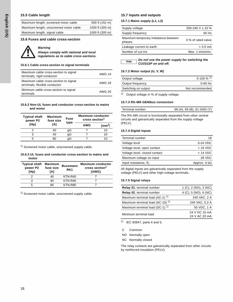
15.5 Cable length
15.6 Fuses and cable cross-section
15.6.1 Cable cross-section to signal terminals
15.6.2 Non-UL fuses and conductor cross-section to mains and motor
1) Screened motor cable, unscreened supply cable.
15.6.3 UL fuses and conductor cross-section to mains and motor
1) Screened motor cable, unscreened supply cable.
15.7 Inputs and outputs
15.7.1 Mains supply (L1, L2)
15.7.2 Motor output (U, V, W)
1) Output voltage in % of supply voltage.
15.7.3 RS-485 GENIbus connection
The RS-485 circuit is functionally separated from other central circuits and galvanically separated from the supply voltage (PELV).
15.7.4 Digital inputs
All digital inputs are galvanically separated from the supply voltage (PELV) and other high-voltage terminals.
15.7.5 Signal relays
1) IEC 60947, parts 4 and 5.
The relay contacts are galvanically separated from other circuits by reinforced insulation (PELV).
Maximum length, screened motor cable 500 ft (152 m)
Maximum length, unscreened motor cable 1000 ft (305 m)
Maximum length, signal cable 1000 ft (305 m)
Warning
Always comply with national and local regulations as to cable cross-sections.
Maximum cable cross-section to signal terminals, rigid conductor
AWG 14
Maximum cable cross-section to signal terminals, flexible conductor
AWG 18
Minimum cable cross-section to signal terminals
AWG 20
Typical shaft power P2
[Hp]
Maximum fuse size
[A]
Fuse type
Maximum conductor cross section1
AWG [mm2]
2 40 gG 7 103 40 gG 7 105 80 gG 7 10
Typical shaft power P2
[Hp]
Maximum fuse size
[A]
BussmannRK1
Maximum conductor cross section1
[AWG]
2 40 KTN-R40 73 40 KTN-R40 75 80 KTN-R80 7
Supply voltage 200-240 V ± 10 %
Supply frequency 60 Hz
Maximum temporary imbalance between phases
3 % of rated value
Leakage current to earth > 3.5 mA
Number of cut-ins Max. 1 time/min.
NoteNote Do not use the power supply for switching the CU331SP on and off.
Output voltage 0-100 % 1)
Output frequency 0-60 Hz
Switching on output Not recommended
Terminal number 68 (A), 69 (B), 61 GND (Y)
Terminal number 18
Voltage level 0-24 VDC
Voltage level, open contact > 19 VDC
Voltage level, closed contact < 14 VDC
Maximum voltage on input 28 VDC
Input resistance, Ri Approx. 4 kΩ
Relay 01, terminal number 1 (C), 2 (NO), 3 (NC)
Relay 02, terminal number 4 (C), 5 (NO), 6 (NC)
Maximum terminal load (AC-1) 1) 240 VAC, 2 A
Maximum terminal load (AC-15) 1) 240 VAC, 0.2 A
Maximum terminal load (DC-1) 1) 50 VDC, 1 A
Minimum terminal load24 V DC 10 mA24 V AC 20 mA
C Common
NO Normally open
NC Normally closed
18

En
gli
sh
(U
S)
15.7.6 Analog input1) The factory setting is voltage signal "U".
All analog inputs are galvanically separated from the supply voltage (PELV) and other high-voltage terminals.
15.8 Sound pressure level
The sound pressure of the CU331SP is maximum 70 dB(A).
The sound pressure level of a motor controlled by a Variable frequency drive may be higher than that of a corresponding motor which is not controlled by a variable frequency drive.
16. DisposalThis product or parts of it must be disposed of in an environmentally sound way:
1. Use the public or private waste collection service.
If this is not possible, contact the nearest Grundfos company or service workshop.
Subject to alterations.
Terminal number 54
Current signal A54 = "I" 1)
Current range 0-20, 4-20 mA
Input resistance, Ri Approx. 200 ΩMaximum current 30 mA
Maximum fault, terminals 53, 54 0.5 % of full scale
19

20

21

22

Gru
nd
fos
co
mp
an
iesUSA
GRUNDFOS Pumps Corporation 17100 West 118th TerraceOlathe, Kansas 66061Phone: +1-913-227-3400 Telefax: +1-913-227-3500
CanadaGRUNDFOS Canada Inc. 2941 Brighton Road Oakville, Ontario L6H 6C9 Phone: +1-905 829 9533 Telefax: +1-905 829 9512
MéxicoBombas GRUNDFOS de México S.A. de C.V. Boulevard TLC No. 15Parque Industrial Stiva AeropuertoApodaca, N.L.C.P. 66600Phone: +52-81-8144 4000 Telefax: +52-81-8144 4010

www.grundfos.us
L-CU-TL-012
98369129 0213
ECM: 1110089 The
nam
e G
rund
fos,
the
Gru
ndfo
s lo
go, a
nd b
e t
hin
k i
nn
ov
ate
are
regi
ster
ed tr
adem
arks
ow
ned
by G
rund
fos
Hol
ding
A/S
or G
rund
fos
A/S,
Den
mar
k. A
ll rig
hts
rese
rved
wor
ldw
ide.
© C
opyr
ight
Gru
ndfo
s H
oldi
ng A
/S
www.grundfos.com