cti 2572 installation and operation guide - napa · installation and operation guide . version 2.5...
TRANSCRIPT

CTI 2572-B / 2500C-2572-B
ETHERNET TCP/IP MODULE
INSTALLATION AND OPERATION GUIDE Version 2.5

ii CTI 2572-B Installation and Operation Guide
Copyright 2016 Control Technology Inc. All rights reserved
This manual is published by Control Technology Inc. (CTI) 5734 Middlebrook Pike, Knoxville, TN 37921. This manual contains references to brand and product names which are tradenames, trademarks, and/or registered trademarks of Control Technology Inc. Siemens®, SIMATIC®, and Series 505®, and 505® are registered trademarks of Siemens AG. Other references to brand and product names are tradenames, trademarks, and/or registered trademarks of their respective holders.
DOCUMENT DISCLAIMER STATEMENT Every effort has been made to ensure the accuracy of this document; however, errors do occasionally occur. CTI provides this document on an “as is” basis and assumes no responsibility for direct or consequential damages resulting from the use of this document. This document is provided without express or implied warranty of any kind, including but not limited to the warranties of merchantability or fitness for a particular purpose. This document and the products it references are subject to change without notice. If you have a comment or discover an error, please call us toll-free at 1-800-537-8398 or email us at [email protected]. REVISION HISTORY 1.0 7/12/2016 Initial Release 2.0 9/20/2016 Added 2500C-2572-B module information
Added PWR bit to WX/WY Quick Reference diagram 2.1 10/11/16 Revised Document Title 2.2 11/8/2016 Corrected the label for the illustration of the 2500C-2572-B PC board 2.3 1/3/2017 Corrected incorrect cross reference in section 2.3. 2.4 1/9/2017 Added error code 029B to the General Memory Transfer error table
Revised description for error code 029C Deleted error codes 249B and 249C in the PLC CAMP Client error table
2.5 3/22/2017 Removed references to password protection. To be restored when the feature is available.

i CTI 2572-B Installation and Operation Guide
PREFACE
This Installation and Operation Guide provides reference information for the CTI 2572-B Ethernet TCP/IP Module. The information in this manual is directed to individuals who will be installing and/or using the module, developing PLC logic to control or monitor the product operation, or maintaining the product. We assume you are familiar with the installation and operation of: 1) CTI 2500® Series and/or Siemens SIMATIC® 505 programmable controllers, 2) Ethernet local area networks, 3) Transmission Control Protocol/Internet Protocol (TCP/IP). Please refer to the appropriate user documentation for specific information on programmable controllers and I/O modules.

ii CTI 2572-B Installation and Operation Guide
USAGE CONVENTIONS
NOTE: Notes alert the user to special features or procedures.
CAUTION: Cautions alert the user to procedures that could damage equipment.
WARNING: Warnings alert the user to procedures that could damage equipment and endanger the user.

i CTI 2572-B Installation and Operation Guide
TABLE OF CONTENTS
CHAPTER 1. PRODUCT OVERVIEW ........................................................................... 1 1.1. Introduction ............................................................................................................. 1 1.2. Compatibility ........................................................................................................... 2
CHAPTER 2. INSTALLATION ....................................................................................... 3 2.1. Installation Planning ................................................................................................ 3 2.2. Unpacking the Module ............................................................................................ 6 2.3. Setting the 2572-B Option Switches ........................................................................ 6 2.4. Physical Installation ................................................................................................. 9 2.5. Connecting the Ethernet Cable ............................................................................... 9 2.6. Initial Power On ....................................................................................................... 9 2.7. Entering the Module into the PLC I/O Configuration ................................................ 9 2.8. Storing Network Parameters in Flash..................................................................... 10 2.9. Module Checkout .................................................................................................. 11
CHAPTER 3. MODULE OPERATION .......................................................................... 13 3.1. Front Panel Features ............................................................................................. 13 3.2. Module Startup...................................................................................................... 14 3.3. Normal Operation .................................................................................................. 15
CHAPTER 4. CAMP SERVER ..................................................................................... 17 4.1. Overview ............................................................................................................... 17 4.2. Operation .............................................................................................................. 17 4.3. Connections .......................................................................................................... 17 4.4. Error Processing ................................................................................................... 17
CHAPTER 5. MODBUS TCP SERVER........................................................................ 19 5.1. Overview ............................................................................................................... 19 5.2. Variable Mapping .................................................................................................. 19 5.3. Address Translation .............................................................................................. 19 5.4. Supported Modbus Function Codes (FC) .............................................................. 20 5.5. Modbus Exception Codes...................................................................................... 20 5.6. Diagnostic Statistics .............................................................................................. 20
CHAPTER 6. ETHERNET/IP SERVER ........................................................................ 21 6.1. Overview ............................................................................................................... 21 6.2. Tag Types Supported ............................................................................................ 22 6.3. 2572-B Configuration ............................................................................................ 22 6.4. Application Example .............................................................................................. 22
CHAPTER 7. PLC COMMAND INTERFACE OVERVIEW ........................................... 27 7.1. Module WX/WY Words ......................................................................................... 27 7.2. Command Blocks .................................................................................................. 28 7.3. WX/WY Command Block Interaction ..................................................................... 29
CHAPTER 8. START NETWORK SERVICES COMMAND ......................................... 31
CHAPTER 9. CAMP CLIENT COMMANDS ................................................................ 37 9.1. Overview ............................................................................................................... 37

ii CTI 2572-B Installation and Operation Guide
9.2. CAMP IP Multicast Operation ................................................................................ 37 9.3. Create Socket Command ...................................................................................... 38 9.4. Close Socket Command ........................................................................................ 40 9.5. Memory Transfer Commands ................................................................................ 40 9.6. Application Examples ............................................................................................ 48
CHAPTER 10. TROUBLESHOOTING ......................................................................... 59 10.1. Troubleshooting Aids........................................................................................... 59 10.2. General Troubleshooting Techniques .................................................................. 60 10.3. Module Startup Problems .................................................................................... 60 10.4. Communications Problems ................................................................................. 62 10.5. Performance Problems ........................................................................................ 63 10.6. PLC Logic Problems ........................................................................................... 64 10.7. Development and Debugging Tips ...................................................................... 65
CHAPTER 11. FIRMWARE UPDATE .......................................................................... 69 11.1. Overview ............................................................................................................. 69 11.2. Obtaining New Firmware ..................................................................................... 69 Updating 2572-B Firmware .......................................................................................... 69
APPENDIX A. ERROR CODES ................................................................................... 71 2572-B System Error Codes......................................................................................... 71 General Memory Transfer Error Codes ......................................................................... 73 Start Network Services Error Codes .............................................................................. 78 CAMP Server Error Codes............................................................................................ 79 PLC CAMP Client Error Codes ..................................................................................... 81
APPENDIX B. PLC COMMAND INTERFACE ............................................................. 87 General Description ...................................................................................................... 87 WX/WY Description ..................................................................................................... 89 Command Timing Diagrams ......................................................................................... 96
APPENDIX C. IP ADDRESS INFORMATION ........................................................... 103 IP Address Nomenclature .......................................................................................... 103 Using the Subnet Mask .............................................................................................. 104 Converting between CIDR and Dotted Decimal Notation............................................. 106 Selecting an IP Address ............................................................................................. 106 Selecting a Multicast Address .................................................................................... 107
HARDWARE SPECIFICATIONS................................................................................ 109
LIMITED PRODUCT WARRANTY ............................................................................. 110
REPAIR POLICY........................................................................................................ 112

CTI 2572-B / 2500C-2572-B Installation and Operation Manual 1
CHAPTER 1. PRODUCT OVERVIEW
1.1. Introduction The 2572-B Ethernet TCP/IP module provides network services for CTI 2500 Series® Classic controllers and Siemens SIMATIC 505® programmable logic controllers. The 2572-B module is designed to install in a CTI 2500 Series classic base or a Siemens Series 505® base. Employing a new microprocessor and related components, the 2572-B module is a direct replacement for the 2572-A Ethernet TCP/IP module. The 2500C-2572-B Ethernet TCP/IP module provides network services for CTI 2500 Series® Compact Controllers. The 2500C-2572-B module installs in a CTI 2500 Series compact base. Both modules are Special Function modules, which communicate with the PLC using the SFIO (Special Function I/O) protocol. Network workstations and control devices can use the services of these modules to read data from the PLC, write data to the PLC, program the PLC, and exercise supervisory control over the PLC operation. In addition, PLC logic can use the facilities of the CTI 2572-B and 2500C-2572-B modules to access data in other CTI 2500 Series® controllers or Siemens SIMATIC 505® PLCs. The modules support the following communications protocols:
• Camp Server: Allows a client to access PLC data and control PLC operation using the CTI CAMP or the Siemens Task Code protocols.
• Modbus Server: Allows a client to access PLC data using the Modbus TCP (Open Modbus) protocol.
• EtherNet/IP Server: Allows Allen Bradley Logix® controllers to read and write PLC data stored in V memory.
• Camp Client: Allows the PLC to read and write data stored in V memory on other PLCs. They connect to an Ethernet network via a CAT 5e RJ-45 connector. The network port supports 10Mb or 100Mb Ethernet data link (half or full duplex operation). The firmware includes a full function TCP/IP stack that supports both TCP and UDP protocols. The module provides extensive diagnostic facilities, accessible via an embedded web browser, to aid in the detection and correction of network problems. In addition, the web browser can be used to configure module operating parameters and to initiate firmware update.

CTI 2572-B / 2500C-2572-B Installation and Operation Manual 2
1.2. Compatibility 2572-B The 2572-B mode is designed to be a direct application replacement for the CTI 2572-A module.
• The module uses the same PLC command interface as the CTI 2572 and 2572-A modules, allowing existing PLC logic to control the operation of the module.
• The CAMP server is compatible with existing CAMP and task code drivers.
• The Modbus Server and EtherNet/IP server functionality is identical to the corresponding 2572-A protocol managers.
Some features of the 2572-A module that are unrelated to the product application are not supported:
• The TFTP method used by the 2572-A module has been replaced by a method initiated by the embedded web browser;
• The serial port, which provided an alternate means to set the IP parameters address on the 2572-A, is not present;
• The Module ID switches, used to generate a DHCP client ID, are not present;
• The SYSLOG client capability is no longer supported. 2500C-2572-B Except for the smaller form factor, the 2500C-2572-B module is functionally equivalent to the 2572-B module. It uses the same command interface as the 2572, 2572-A, and 2572-B modules. Consequently, user logic designed to control these modules will also work with the 2500C-2572-B module. HMI and SCADA workstation drivers that can access data in CTI 2500 Series Classic controllers via the 2572-A or 2572-B also work with the 2500C-2572-B Module to access data in CTI 2500 Series Compact controllers.
CTI 2572-B / 2500C-2572-B Installation and Operation Manual 3
CHAPTER 2. INSTALLATION
The installation of the Model 2572-B Ethernet TCP/IP Adapter Module consists of the following steps:
1) Planning the installation,
2) Unpacking and configuring the module,
3) Physical installation,
4) Setting IP information,
5) Connecting cables,
6) Checking the module operation.
2.1. Installation Planning
Choosing Ethernet Media The 2572-B module attaches directly to 10BaseT or 100Base TX media (Shielded or Unshielded Twisted Pair) via the RJ-45 connector. Ensure that the cables you use for Ethernet communications meet the appropriate IEEE 802.3 specifications and are appropriate for the environment in which you are operating. CTI recommends you use cables rated Category 5e or better.
Selecting an IP Address and Other Network Parameters Before proceeding, you must determine what IP address you will assign to the module, the subnet mask to use, and the IP address of the default gateway/router. If you are connecting to an existing network, your network administrator should provide this information. If you are installing a stand-alone network, you should choose from within the set of “private” IP addresses specified in RFC 1597. See APPENDIX D. IP ADDRESS INFORMATION for a description of the IP Address numbering conventions.
Choosing a Module Startup Method Before the 2572-B will communicate using TCP/IP, the IP address and related parameters must be set and the module network server must be started. There are two startup options, described below.
AutoStart If you choose this method, the module will automatically start the network server using IP parameters stored in flash memory. The primary advantage of this approach is that it eliminates the need for additional PLC logic to initiate startup. See Section 2.8. Storing Network Parameters in Flash. The disadvantage of this method is that, when installing or replacing modules, you must manually configure the IP parameters of the replacement module. In addition, if you arbitrarily swap 2572-B modules between PLCs, the IP address will move with the module. The effect of inadvertently swapping IP addresses could cause process problems, since communications directed at one PLC would actually be going to another PLC.

CTI 2572-B / 2500C-2572-B Installation and Operation Manual 4
PLC Start Using this method, PLC logic is used to set the IP address of the module during startup. The Start Network Services command, triggered by PLC logic, sets the IP parameters based on data stored in V memory. Once the IP parameters are successfully set, the network TCP/IP services are started An important advantage to this method is that it eliminates the need to manually configure the module during the initial installation or during a replacement operation. In addition, since the network parameters are stored in PLC memory, the module IP address remains associated with the PLC even when modules are swapped. The primary disadvantage is that it requires a small amount of additional ladder logic. In addition, if the PLC is not in run mode (not executing logic) the module will not start up. The PLC logic to perform this function is described in CHAPTER 8. START NETWORK SERVICES COMMAND.
Choosing between TCP and UDP Protocols Many HMI drivers and OPC servers will allow you to select either TCP (Transmission Control Protocol) or UDP (User Datagram Protocol) for delivering messages. The 2572-B client functions also allow you to choose between the two. The following information is provided to help you determine which is right for your situation.
UDP Protocol The UDP protocol allows you to send a message to another node without previously establishing a logical connection to the other node. This method, called connectionless delivery, uses less network bandwidth, consumes fewer module resources, and usually results in faster response times. Although the delivery of UDP messages is not acknowledged by TCP/IP, higher level protocols, such as CAMP, confirm that the message was received and that the requested service performed.
NOTE: In most installations, UDP is the preferred protocol for HMI applications that continuously read data
from the PLC.
TCP Protocol The TCP protocol requires that a logical connection be established between two points before messages can be sent. This method, called connection-oriented services, provides delivery acknowledgement and message flow control within the TCP/IP protocol. If a message is not delivered correctly, the TCP protocol will cause the message to be re-transmitted. Although TCP may be slightly slower than UDP because additional acknowledgement messages must be transmitted and evaluated, there are several instances in which it should be used:
1. If you have a network whose quality requires a significant amount of message re-transmission, TCP can provide better overall performance because the TCP is quicker at delivery acknowledgement and retry than the application level, which typically relies on a message timeout measured in seconds.
2. If you are using the Internet to access the module, you may want to consider TCP. When traversing the Internet, some gateways may break a packet up into smaller chunks, a process called fragmentation. The smaller packets may be sent via different paths and could arrive out of order. TCP will ensure that the fragmented packets will be re-assembled in the correct order, while UDP will not.

CTI 2572-B / 2500C-2572-B Installation and Operation Manual 5
Maximizing Performance For best performance, you should place the module in a local rack (the one containing the PLC). Using a Special Function module such as the 2572-B in a Remote I/O rack imposes significant additional communications overhead and noticeably increases the scan time of the PLC. This effect is especially noticeable when transferring large blocks of data.
NOTE: The 2572-B will not work in a remote rack using the Profibus Remote Base Controller (RBC).
Profibus does not support Special Function modules. The module is allowed to access to the PLC only once during a scan cycle. Ensure that the task codes per scan setting of the PLC is set to eight (8). This allows the maximum number of PLC access requests to be processed in a single scan. Set the PLC to the shortest acceptable scan time or use the variable scan time setting. Excessive broadcast and/or multicast traffic can degrade performance. If you experience excessive broadcast/multicast traffic, you will need to segment your network into separate Ethernet broadcast domains or IP subnets.
Security Considerations Since the 2572-B module communicates on a TCP/IP network, you should take precautions to prevent someone from inadvertently or maliciously interrupting the operation of the module. Some actions you can take include: Use a dedicated network that does not connect to other networks. By eliminating external physical
connections, you limit access to only those on the network segment.
Use a router with firewall capability to connect to other networks. If isolating the network from other networks is not practical, you can use “firewall” techniques to limit access from the outside.
Disable routing for the 2572-B modules. If you want to prevent access to the 2572-B modules from replying to requests outside the local network segment but you want to allow your PC workstations to access the corporate network, disable routing on the 2572-B module. You can accomplish this by setting the Default Gateway/Router IP address to 0.0.0.0.
Use hardware lockout protection to prevent configuration changes or firmware download. Switches on the board can be used to disable these functions (see section 2.3. Setting the 2572-B Option Switches).
Power Requirements
The CTI 2572-B module consumes a maximum of 2.8 watts of +5 VDC power from the backplane.

CTI 2572-B / 2500C-2572-B Installation and Operation Manual 6
2.2. Unpacking the Module Open the shipping carton and remove the special anti-static bag that contains the module. After discharging any static build-up, remove the module from the static bag. Do not discard the static bag. Always use this bag for protection against static damage when the module is not inserted into the I/O base.
CAUTION: The components on the 2572-B module printed circuit card can be damaged by static
electricity discharge. To prevent this damage, the module is shipped in a special anti-static bag. Static control precautions should be followed when removing the module from the bag
and when handling the printed circuit card during configuration.
2.3. Setting the 2572-B Option Switches Using the option switches on the 2572-B circuit board, you can designate how the module will operate. The following illustration indicates the location of the switchblocks on both products. 2572-B 2500C-2572-B
Figure 1. Switchblock Locations

CTI 2572-B / 2500C-2572-B Installation and Operation Manual 7
The function of the switches is described below.
Figure 2. Option Switches SW1, SW2: These switches are unused and may be set to any position with no effect. SW3: This switch position is reserved for future use. It should be set to the open position to prevent a future use from unintentionally affecting the module operation. SW4: Startup Option: This switch selects how the 2572-B module will start network services.
Startup Option
Position SW4
AutoStart Closed PLC Start Open
In the AUTOSTART position, the module will automatically start up using parameters stored in non-volatile (flash) memory. In the PLC START position, the module will start up in a limited function mode, using the parameters stored in flash. It will then wait for PLC logic to trigger the START NETWORK SERVICES command before starting the network services that allow access to the PLC. CHAPTER 8. START NETWORK SERVICES COMMAND describes the PLC logic required. When the command is successfully completed, the IP parameters obtained from the PLC will be written to non-volatile (flash) memory.
NOTE: When using the PLC Start Option, the PLC must be in run mode before the module will start up in
full function mode.

CTI 2572-B / 2500C-2572-B Installation and Operation Manual 8
SW5: Configuration Lock. This switch allows you to prevent changes to the module IP parameters via the Ethernet network. If the PLC Start option is selected, PLC logic will still be able to change the module IP parameters.
Configuration Lock
Position SW5
Locked Closed Unlocked Open
When set to the LOCKED position, changes to the module IP parameters via the embedded web server Module Configuration page will be prevented. In the UnlOCKED position changes will be allowed. SW6: Firmware Update. This switch allows you to prevent updates to the module firmware. When set to the CLOSED position, this switch prevents the user from the initiating firmware update using the embedded web server Update Firmware page.
Firmware Update
Position SW6
Disabled Closed Enabled Open
SW7 – SW10: These switches are reserved for future use. They should be set to the open position to prevent a future use from unintentionally affecting the module operation. SW11: PLC Interface Mode. This switch allows you to select a PLC interface that is compatible with the CTI 2572 module and other Special Function I/O modules. By default, the 2572-B module uses a high performance interface mode that increases the amount of data per scan that can be transferred to and from the PLC and sets the task codes per scan to 8. In most cases, you should use the high performance mode. However, in instances where minimizing PLC scan time is required, you may wish to use compatibility mode. This is especially true when the 2572-B module is installed in a remote base where high performance mode can significantly increase the PLC scan time.
Interface Mode Position SW11
Compatibility Closed High Performance Open
When this switch is set to the CLOSED position, the Special Function Interface will use the compatibility mode. When the switch set to the OPEN position, the module will use a high performance interface mode. SW12: This switch is reserved for future use. It should be set to the open position to prevent a future use from unintentionally affecting the module operation
NOTE The Option switches are read only at module startup. If you change the switch position after
startup, you must restart the module before the setting will take effect.
CTI 2572-B / 2500C-2572-B Installation and Operation Manual 9
2.4. Physical Installation
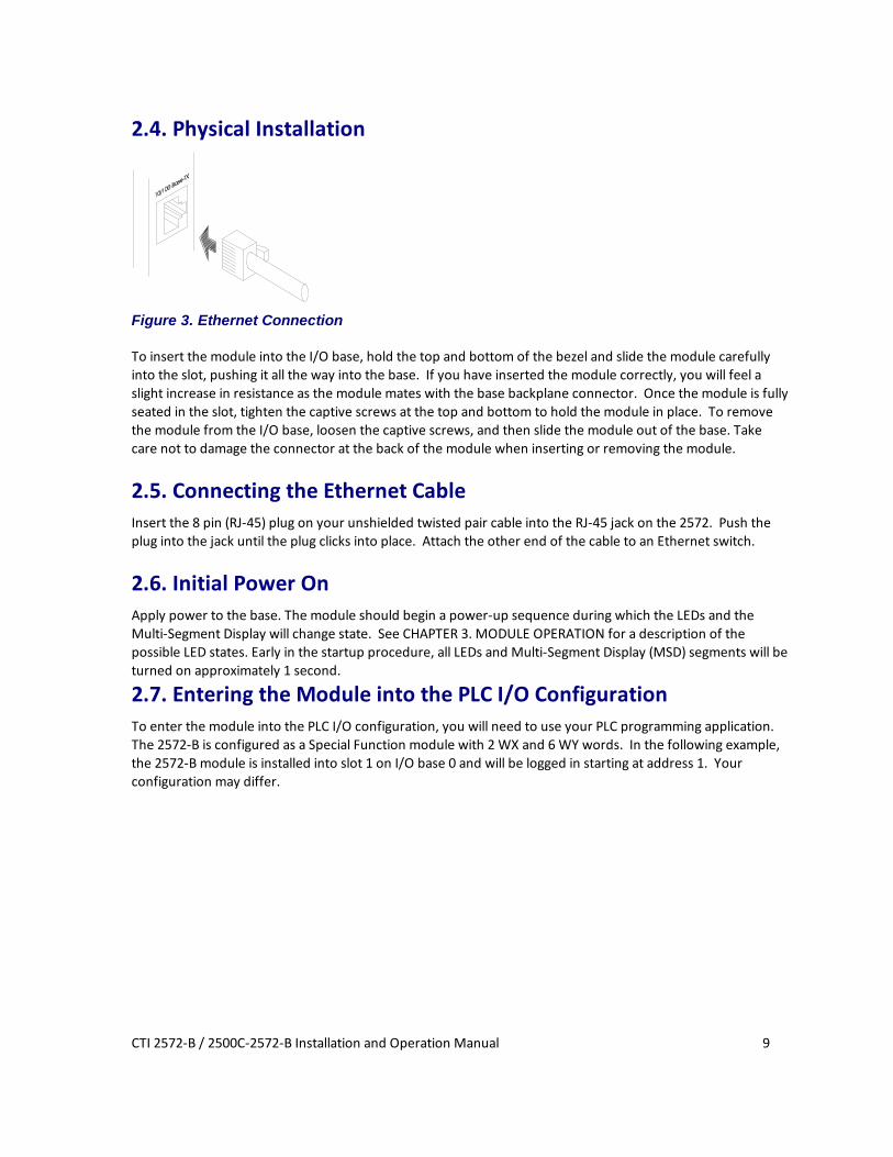
Figure 3. Ethernet Connection
To insert the module into the I/O base, hold the top and bottom of the bezel and slide the module carefully into the slot, pushing it all the way into the base. If you have inserted the module correctly, you will feel a slight increase in resistance as the module mates with the base backplane connector. Once the module is fully seated in the slot, tighten the captive screws at the top and bottom to hold the module in place. To remove the module from the I/O base, loosen the captive screws, and then slide the module out of the base. Take care not to damage the connector at the back of the module when inserting or removing the module.
2.5. Connecting the Ethernet Cable Insert the 8 pin (RJ-45) plug on your unshielded twisted pair cable into the RJ-45 jack on the 2572. Push the plug into the jack until the plug clicks into place. Attach the other end of the cable to an Ethernet switch.
2.6. Initial Power On Apply power to the base. The module should begin a power-up sequence during which the LEDs and the Multi-Segment Display will change state. See CHAPTER 3. MODULE OPERATION for a description of the possible LED states. Early in the startup procedure, all LEDs and Multi-Segment Display (MSD) segments will be turned on approximately 1 second.
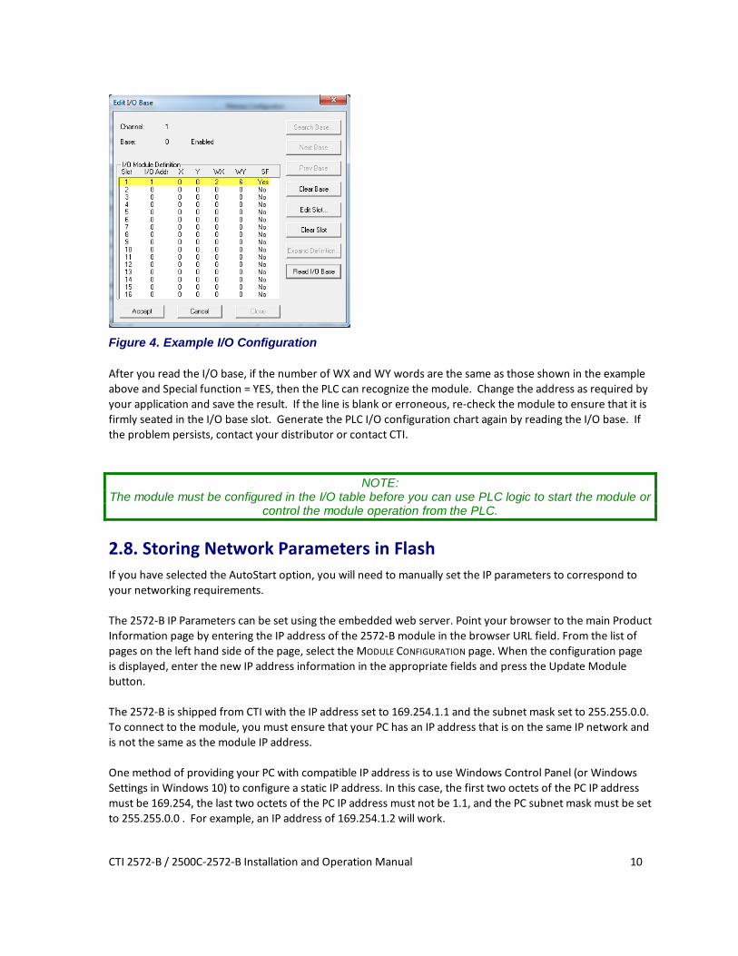
2.7. Entering the Module into the PLC I/O Configuration To enter the module into the PLC I/O configuration, you will need to use your PLC programming application. The 2572-B is configured as a Special Function module with 2 WX and 6 WY words. In the following example, the 2572-B module is installed into slot 1 on I/O base 0 and will be logged in starting at address 1. Your configuration may differ.
CTI 2572-B / 2500C-2572-B Installation and Operation Manual 10
Figure 4. Example I/O Configuration After you read the I/O base, if the number of WX and WY words are the same as those shown in the example above and Special function = YES, then the PLC can recognize the module. Change the address as required by your application and save the result. If the line is blank or erroneous, re-check the module to ensure that it is firmly seated in the I/O base slot. Generate the PLC I/O configuration chart again by reading the I/O base. If the problem persists, contact your distributor or contact CTI.
NOTE: The module must be configured in the I/O table before you can use PLC logic to start the module or
control the module operation from the PLC.
2.8. Storing Network Parameters in Flash If you have selected the AutoStart option, you will need to manually set the IP parameters to correspond to your networking requirements. The 2572-B IP Parameters can be set using the embedded web server. Point your browser to the main Product Information page by entering the IP address of the 2572-B module in the browser URL field. From the list of pages on the left hand side of the page, select the MODULE CONFIGURATION page. When the configuration page is displayed, enter the new IP address information in the appropriate fields and press the Update Module button. The 2572-B is shipped from CTI with the IP address set to 169.254.1.1 and the subnet mask set to 255.255.0.0. To connect to the module, you must ensure that your PC has an IP address that is on the same IP network and is not the same as the module IP address. One method of providing your PC with compatible IP address is to use Windows Control Panel (or Windows Settings in Windows 10) to configure a static IP address. In this case, the first two octets of the PC IP address must be 169.254, the last two octets of the PC IP address must not be 1.1, and the PC subnet mask must be set to 255.255.0.0 . For example, an IP address of 169.254.1.2 will work.

CTI 2572-B / 2500C-2572-B Installation and Operation Manual 11
Instead of manually setting a static address, you can cause your PC to generate a compatible address, if your PC is using DHCP (Dynamic Host Configuration Protocol) to obtain an IP address. The IP address 169.254.1.1 is a link local IP address, which is used only to communicate on the local network. When a Windows PC is unable to obtain an IP address from DHCP, it automatically generates a link local address using a feature called Automatic Private IP Addressing. To cause the PC to generate a compatible address, do the following:
• Connect an Ethernet cable directly between your PC and the 2572-B module, • Reboot the PC.
NOTE: It may take several minutes before the PC will stop trying to contact a DHCP server and generate the Link Local address. You can display the IP parameters being used by the PC by opening the Command Prompt window and entering IPCONFIG at the prompt. Once the link local IP address is generated, you can connect by typing http://169.254.1.1 in your browser’s URL box.
2.9. Module Checkout If functioning properly, the 2572-B will respond to an ICMP Echo Request message known as a ping. Using a PC on the local network, open the Command Prompt window and type the following: PING IPaddress where IPaddress is the IP address of the module in dotted decimal format. If the module does not reply, refer to CHAPTER 8. TROUBLESHOOTING.

CTI 2572-B / 2500C-2572-B Installation and Operation Manual 13
CHAPTER 3. MODULE OPERATION
3.1. Front Panel Features
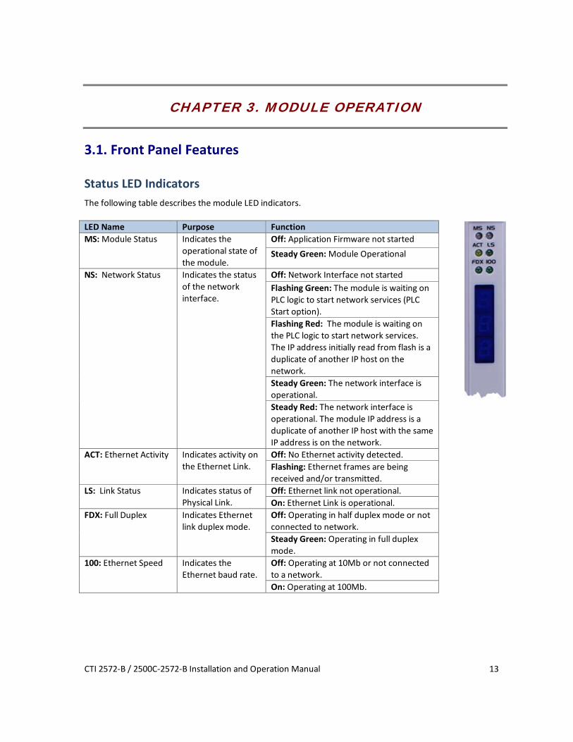
Status LED Indicators The following table describes the module LED indicators. LED Name Purpose Function MS: Module Status
Indicates the operational state of the module.
Off: Application Firmware not started Steady Green: Module Operational
NS: Network Status Indicates the status of the network interface.
Off: Network Interface not started Flashing Green: The module is waiting on PLC logic to start network services (PLC Start option). Flashing Red: The module is waiting on the PLC logic to start network services. The IP address initially read from flash is a duplicate of another IP host on the network. Steady Green: The network interface is operational. Steady Red: The network interface is operational. The module IP address is a duplicate of another IP host with the same IP address is on the network.
ACT: Ethernet Activity
Indicates activity on the Ethernet Link.
Off: No Ethernet activity detected. Flashing: Ethernet frames are being received and/or transmitted.
LS: Link Status Indicates status of Physical Link.
Off: Ethernet link not operational. On: Ethernet Link is operational.
FDX: Full Duplex Indicates Ethernet link duplex mode.
Off: Operating in half duplex mode or not connected to network. Steady Green: Operating in full duplex mode.
100: Ethernet Speed Indicates the Ethernet baud rate.
Off: Operating at 10Mb or not connected to a network. On: Operating at 100Mb.

CTI 2572-B / 2500C-2572-B Installation and Operation Manual 14
Multi-Segment Display (MSD) The Multi-Segment Display (MSD) is located below the status LEDs. During normal operation the MSD will display certain status information and the TCP/IP address of the module and the subnet mask in CIDR format. CIDR format is a compact way of displaying the network mask. See APPENDIX C. IP ADDRESS INFORMATION for more information regarding CIDR format.
Reset Button Some module functions, such as reading module switch settings or using new IP parameters stored in flash, are performed only at startup. The Reset Button is a momentary contact switch that allows you to restart the module without having to cycle power to the base. It is recessed to prevent inadvertent use. To reset the module, use a small object such as the tip of a ball point pen to depress and hold the switch for approximately one second. When the switch is released, the module will begin the startup sequence.
NOTE: To reset the parameters stored in flash memory to factory default values, hold the reset button
down for 10 seconds or more.
Ethernet Port The 2572-B provides a Category 5e RJ-45 connector which attaches directly to Unshielded Twisted Pair (UTP) or Shielded Twisted Pair (STP) Ethernet cabling. The port complies with the IEEE 802.3 specifications for 10BaseT and 100Base TX and will operate in either half or full duplex mode. The speed and mode are automatically negotiated by the module in accordance with IEEE 802.3u specifications. When attaching to a hub or switch that does not support auto-negotiation, the port will default to 10Mb half-duplex.
3.2. Module Startup After power is applied to the 2572-B module, when the Reset button is pressed, or when the module is restarted by software or the reset switch, the module will begin the startup procedure. After the application firmware is running, all LEDs and MSD segments will be illuminated for approximately one second (multicolor LEDs will be red for ½ second and green for ½ second), and then will be turned off. This serves a display test and as an indication that module startup is in process.
AutoStart Mode If the AUTOSTART option is selected (via SW4), the module will start up using the IP address stored in flash. If the startup is successful, all module network services, including the embedded web server, CAMP Server, Modbus TCP Server, and the Ethernet IP server, will be enabled. After startup, the MS LED should be STEADY
GREEN and the Multi-Segment Display (MSD) should display the module IP address and subnet mask (in CIDR format). The NS LED should be either STEADY RED if a duplicate IP has been detected (indicating the module IP address is the same as another IP Host on the network) or STEADY GREEN if no duplicate has been detected.
PLC Start Mode If the PLC START option is selected, the module will start up in a limited function mode using the IP address stored in flash, enabling only the embedded web server. Then it will wait on the PLC logic to set the IP address and enable the application servers using the Start Network Services command. While the module is waiting

CTI 2572-B / 2500C-2572-B Installation and Operation Manual 15
on the PLC command, the MSD should display the characters “PLC” interleaved with the IP address read from flash. The NS LED should be FLASHING RED if the IP address read from flash memory is a duplicate of another IP host on the network or FLASHING GREEN if no duplicate has been detected. While in the state, you can access the module web server pages only. Once the PLC successfully initiates the Start Network Services command, the module will begin using the IP parameters specified in the command and will enable all module network services. The MSD should display the IP address and subnet mask (in CIDR format) specified by the PLC logic. The NS LED should be STEADY RED if a duplicate IP address is detected; otherwise, the NS LED should be STEADY GREEN. If the LED states are different than those described above, then a startup error has occurred. See CHAPTER 10. TROUBLESHOOTING for more information.
3.3. Normal Operation
Server Operation To use the 2572-B module servers, including the CAMP server, Modbus TCP server, or EtherNet IP Server, no PLC logic is required. You simply provide a client application that communicates with the module. For example, your HMI application, using a CAMP driver or OPC server that supports CAMP, can be used to read and write PLC data. The CAMP server can also be used to program the PLC over the Ethernet link.
Client Operation To use the module to perform client operations (initiating data requests), you must include PLC logic that triggers the module operation. See CHAPTER 9. CAMP CLIENT COMMANDS.


CTI 2572-B / 2500C-2572-B Installation and Operation Manual 17
CHAPTER 4. CAMP SERVER
4.1. Overview The CAMP server enables client applications using Common ASCII Messaging Protocol (CAMP)) to access controller data element types supported by the CTI 2500 Series® controllers and Siemens Series 505® controllers. First implemented on the CTI 2572 Ethernet network module, the CAMP protocol is widely used by HMI (Human Machine Interface) panels and SCADA (Supervisory Control and Data Acquisition) equipment to communicate with CTI 2500 Series® controllers and Siemens Series 505® controllers. The CAMP server also allows these controllers to be programmed via the network using PLC Workshop, programming software from FasTrak Softworks. The CAMP protocol includes two sub-protocols: Data Transfer and Packed Task Code. The Data Transfer sub-protocol is an efficient means to read or write large blocks of data (up to 256 words). The Packed Task Code sub-protocol allows up to 15 task code requests and responses to be transferred in a block of Ethernet data. The CAMP server also supports Siemens Series 505 task codes that are sent using the NITP protocol.
4.2. Operation The CAMP server translates the data requests contained in a CAMP or NITP message to a Special Function I/O (SFIO) format that can be processed by the PLC. SFIO requests are placed in a queue in the order they were received and transmitted to the PLC during the SFIO portion of the PLC scan when requested by the PLC. The PLC will process a limited number of requests each scan. For example, the PLC will process a maximum of 8 task code requests each scan. When replies are received from the PLC, they are translated to a CAMP or NITP message and transmitted to the client that initiated the request.
4.3. Connections The CAMP server will support up to 24 TCP connections. In addition, it supports UDP and UDP multicast, which are connectionless. Although the number of UDP clients that can access the CAMP server is unlimited, an excessive number of clients can substantially increase response times. The CAMP server can be configured to listen on one UDP multicast address.
4.4. Error Processing If a protocol error or CAMP Data Transfer occurs, an error code is returned to the client within the CAMP protocol. If an error occurs with a task code request (CAMP Packed Task Code or NITP request), an error code is returned within the task code error reply. See APPENDIX A. ERROR CODES for a description of the error codes.

CTI 2572-B / 2500C-2572-B Installation and Operation Manual 18
CTI 2572-B / 2500C-2572-B Installation and Operation Manual 19
CHAPTER 5. MODBUS TCP SERVER
5.1.Overview Modbus was originally developed by the Modicon Corporation as a protocol for communicating with their line of programmable controllers. Over time, the protocol became widely used for data access in industrial control applications. The Modbus TCP Protocol (also known as Open Modbus) is essentially the original serial Modbus RTU protocol modified for transmission via TCP/IP. Modbus TCP is based on open specifications managed by the Modbus Organization. The Modbus TCP server starts automatically using TCP Port 502. There is no configuration or startup logic required.
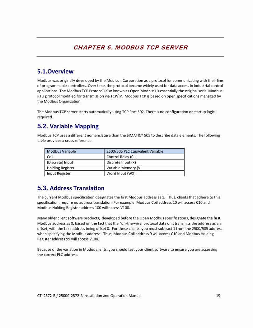
5.2. Variable Mapping Modbus TCP uses a different nomenclature than the SIMATIC® 505 to describe data elements. The following table provides a cross reference.
Modbus Variable 2500/505 PLC Equivalent Variable Coil Control Relay (C ) (Discrete) Input Discrete Input (X) Holding Register Variable Memory (V) Input Register Word Input (WX)
5.3. Address Translation The current Modbus specification designates the first Modbus address as 1. Thus, clients that adhere to this specification, require no address translation. For example, Modbus Coil address 10 will access C10 and Modbus Holding Register address 100 will access V100. Many older client software products, developed before the Open Modbus specifications, designate the first Modbus address as 0, based on the fact that the “on-the-wire’ protocol data unit transmits the address as an offset, with the first address being offset 0. For these clients, you must subtract 1 from the 2500/505 address when specifying the Modbus address. Thus, Modbus Coil address 9 will access C10 and Modbus Holding Register address 99 will access V100. Because of the variation in Modus clients, you should test your client software to ensure you are accessing the correct PLC address.

CTI 2572-B / 2500C-2572-B Installation and Operation Manual 20
5.4. Supported Modbus Function Codes (FC) The following Function Codes are supported by the Modbus/TCP Server function.
FC (dec) FC (hex) Function Codes 505 Variable
Comments
01 01 Read Coil Status C Max number of coils = 2000 02 02 Read Input Status X Max number of inputs = 2000 03 03 Read Holding Register V Max = 125 04 04 Read Input Register WX Max = 125 05 05 Write Single Coil C 06 06 Write Single Register V 07 07 Read Exception Status C 15 0F Write Multiple Coils C Max = 800 16 10 Write Multiple Registers V Max = 100
5.5. Modbus Exception Codes The following Modbus Exception codes may be returned to the Modbus Client in case of an error. Code Name Description 01 Illegal Function Unsupported Function code 02 Illegal Data Address Requested data address not included in the PLC configuration 03 Illegal Data Value Typically indicates a problem in the query structure 04 Slave Device Failure Unrecoverable error occurred while processing the request
5.6. Diagnostic Statistics A full set of diagnostic statistics is maintained for the Modbus/TCP server. These may be accessed by a web browser by setting the URL to the IP address of the module. From the main menu page, select Module Diagnostics and the Modbus/TCP Server.

CTI 2572-B / 2500C-2572-B Installation and Operation Manual 21
CHAPTER 6. ETHERNET/IP SERVER
6.1. Overview Using EtherNet/IP, controllers such as the Allen Bradley Control Logix can read data from and write data to 505 PLCs.
General Description The 2572-B Ethernet I/P (EIP) server allows an EIP client to access data in a CTI 2500 Series PLC or a Siemens SIMATIC® 505 PLC. The EIP Server supports reading data from V memory using a CIP DATA TABLE READ message and writing data to V memory using a CIP DATA TABLE WRITE message. V memory values can be accessed as 16 bit unsigned integers, 16 bit signed integers, 32 bit signed integers, or 32 bit floating point numbers.
V Memory Concepts Variable (V) memory consists of a block of 16 bit registers. The interpretation of the V memory register contents depends on the application accessing the register. V memory registers can be interpreted as a field of 16 bits, an unsigned 16 bit decimal number, a signed 16 bit decimal number, or a set of ASCII characters. In addition, two consecutive registers can be combined and interpreted as a 32 bit number (signed integer or floating point number). For example, if you were writing a block of 2 floating point numbers to V memory starting with V memory 100, the registers would contain the following data. V Memory Address
Data
100 Floating Point Number 1 101 102 Floating Point Number 2 103
Tag Names Tag Names are used to specify the type of memory to be accessed, the format of the data, and the memory locations where the data is stored. A Tag Name consists of a Tag Type and a numeric address. The Tag Type specifies the PLC data element type (e.g. V memory) and the data format. The numeric address specifies the address of the first data register to be accessed. For example, the Tag Type VS would be used to access one or more V memory locations as 16 bit signed integer values. The complete Tag Name VS100 would be used to access V memory address 100 as a signed integer value.

CTI 2572-B / 2500C-2572-B Installation and Operation Manual 22
6.2. Tag Types Supported The following table lists the Tag Types supported by the 2572-B EIP server. Tag Type
Description Tag Name Example
VS V Signed: Accesses a V memory register as a 16 bit signed integer VS2 VU V Unsigned: Accesses a V memory register as a 16 bit unsigned integer. NOTE:
The Control Logix processor does not support 16 bit unsigned integer as a data type. (See VE Tag Type below)
VU335
VF V Float: Accesses a pair of V memory registers as a 32 bit floating point number VF650 VL V Long: Accesses a pair of V memory registers as a 32 bit signed integer VL50 VE V Extended: Converts between a V memory 16 bit unsigned integer and a 32
bit signed integer CIP data element. NOTE: This Tag Type is specifically for controllers that do not support 16 bit unsigned integers See the following section for more information.
VE1000
Figure 5. V memory Tag Types
V Extended (VE) VE is a special Tag Type created for controllers that do not support the 16 bit unsigned integer data type. For Data Table Read operations, it converts unsigned integers stored in a V memory register to a 32 bit signed integers that can be read by the client controller. For Data Table Write operations, it converts one or more 32 bit signed integers sent by the client to a 16 bit unsigned integers, each stored in a single V memory location. The following restrictions are placed on data written to V memory using this Tag Type:
1. The value must be a positive number or 0. 2. The maximum value is 65,535 (0xFFFF).
Values that do not meet these requirements will be rejected by the 2572-B EIP server.
6.3. 2572-B Configuration The EIP Server starts automatically when the module is started up. No additional configuration is required.
6.4. Application Example The following example illustrate how to configure a Control Logix system to communicate with the 2572-B. The example reads unsigned integers stored in V memory and writes a block of signed integers to V memory. The following steps are required to configure the Control Logix system: 1. Define Control Logix tag names that you want to use to hold the data you will read from the 505 PLC and
data you will write to the 505 PLC. For accessing multiple V memory locations, you will need to dimension the tag as an array.
2. Create Message Blocks in your Control Logix program. 3. Configure each Message Block by selecting the following: • Message Type: CIP Data Table Read or CIP Data Table Write • Source Element: For a read operation, this is the 505 Tag Name. For a Write operation this is the Control
Logix Tag Name.

CTI 2572-B / 2500C-2572-B Installation and Operation Manual 23
• Number of Elements: Select the number of data elements to read or write • Destination Element: For a read operation, this is the Control Logix Tag Name. For a write operation, this
is the 505 Tag Name. 4. Specify the Communication options for each Message Block. This includes the path to the target 2572-B
module.
Defining the Control Logix Data Tags First, we will need to define some Control Logix tags. We will define two tags, one to hold the data read from the 505 PLC and the other for the data we will write to the 505 PLC. Different formats are used for the read and the write operations to illustrate the difference in accessing signed and unsigned V memory data.
The tag named VMEMREAD will be used to store the data read from the 505 PLC. The tag data type is defined as a 32 bit signed integer. This is done because we want to read unsigned integers from the PLC, whose values may exceed the maximum that can be stored in a 16 bit signed integer (+32,767). Note that the Control Logix processor does not support unsigned integer tags. This tag is dimensioned to hold 100 values. The tag named VMEMWRITE will be used to store the data that will be written to the 505 PLC. Since we are writing signed 16 bit integers to the 505 PLC, this tag type is defined as a signed 16 bit integer. This tag is dimensioned to hold 50 values.

CTI 2572-B / 2500C-2572-B Installation and Operation Manual 24
Adding Message Blocks to the Logic There are two message blocks added to the logic. One block is used to read the data and one to write the data. The following sections will illustrate how to configure these blocks.
NOTE: Your logic should use a timer (or similar means) to initiate the message block. Allowing the message
to execute every scan could create excessive loading on the 2572-B modules.
Configuring the Read Message Block This message will read 100 unsigned integers from V memory starting at V501. Clicking on the ellipsis button will display the configuration dialog box.
Configuration Tab The configuration tab is used to define the message contents.

CTI 2572-B / 2500C-2572-B Installation and Operation Manual 25
The SOURCE ELEMENT specifies the 505 PLC Tag Name. We want to read a 16 bit unsigned integer into a 32 bit signed Control Logix tag, so we will use the tag type VE. Since we want to start reading at V memory location 501, the complete Tag Name is VE501. We want to read a block of 100 registers, so the NUMBER OF ELEMENTS will be set to 100. The DESTINATION ELEMENT specifies the Control Logix tag that will store the results of the read message. This is the tag we defined earlier. Since this is an array, we will specify that first value returned will be stored in array element 0. Additional values will be stored in subsequent array elements.
Communication Tab The Communication Tab is used to specify the message routing and destination IP address.
The path specifies the route from the controller to the destination. In this case, we will send the message to the backplane (1), to the Ethernet module located in slot 3, out the Ethernet port (2), to the 2572-B module whose IP address is 192.184.177.225. The CACHE CONNECTIONS box is checked to keep the TCP connection established after the message is completed. If you don’t check this box, the Control Logix will close the TCP connection after each message transaction is complete. Continually opening and closing the TCP connection adds unnecessary overhead and reduces performance.

CTI 2572-B / 2500C-2572-B Installation and Operation Manual 26
Configuring the Write Message Block
Configuration Tab
The SOURCE ELEMENT specifies the Control Logix tag that will contain the data to be written to the 505 PLC. We defined this tag in the first section. Since this is an array, we will specify that first value to be written is array element 0. Subsequent elements will be written up to the value specified in the Number of Elements box. Since we want to write a block of 50 registers, the NUMBER OF ELEMENTS will be set to 50. The DESTINATION ELEMENT specifies the 505 PLC Tag Name. We want to write 16 bit unsigned integers, so we will use the tag type VS. Since we want to start reading at V memory location 601, the complete Tag Name is VS601.
Communication Tab The communication tab defines the path to the target 2572-B. See the dialog box for Message_1 above.
CTI 2572-B / 2500C-2572-B Installation and Operation Manual 27
CHAPTER 7. PLC COMMAND INTERFACE OVERVIEW
When used for server applications only, the 2572-B module requires no PLC logic. However, if you wish to set the module IP parameters via a PLC program or initiate communications with other devices supporting the CAMP protocol, the 2572-B provides a PLC Command Interface that allows PLC logic to control the operation of the module. This chapter provides and overview of the PLC Command Interface
NOTE: The 2572-B Command Interface is the same as the CTI 2572-A and CTI 2572 modules.
The PLC Command Interface consists of two structures:
7.1. Module WX/WY Words
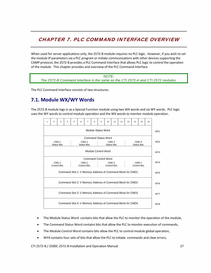
The 2572-B module logs in as a Special Function module using two WX words and six WY words. PLC logic uses the WY words to control module operation and the WX words to monitor module operation.
Command Status Word
1 2 3 4 5 6 7 8 9 10 11 12 13 14 15 16
Module Status Word
CMD 1Status Bits
WX1
WX2
WY3
WY4
WY5
WY6
WY7
WY8
Command Slot 1: V Memory Address of Command Block for CMD1
Command Slot 2: V Memory Address of Command Block for CMD2
Command Slot 3: V Memory Address of Command Block for CMD3
Command Slot 4: V Memory Address of Command Block for CMD4
CMD 2Status Bits
CMD 3Status Bits
CMD 4Status Bits
Command Control WordCMD 1
Control BitsCMD 2
Control BitsCMD 3
Control BitsCMD 4
Control Bits
Module Control Word
• The Module Status Word contains bits that allow the PLC to monitor the operation of the module,
• The Command Status Word contains bits that allow the PLC to monitor execution of commands,
• The Module Control Word contains bits allow the PLC to control module global operation,
• WY4 contains four sets of bits that allow the PLC to initiate commands and clear errors,

CTI 2572-B / 2500C-2572-B Installation and Operation Manual 28
• WY5-WY8 contain the starting V Memory addresses of up to four Command Blocks, described in the
following section.
7.2. Command Blocks Command Blocks specify the command to be executed along with parameters defining the execution. A command block consists of up to 15 contiguous words of V memory, as illustrated below. The first three words are common to all command blocks. The remaining words contain command parameters, which vary with each command. See the Illustration below.
Offset Contents Description 0 Command Error Word When an error occurs, the module will
write an error code to this offset. User logic should clear this error code (set it to 0) after a successful attempt.
1 Command The command code specifies the function to be performed.
2 Connection Number (19291 - 19299)
The connection number is used by the 2572-B module to identify a command instance. Connection numbers must be unique and be within the range allowed by the command.
3 -15 Command Parameters Values that specify how the command will be executed.
In this manual, when command blocks are specified, a bold entry indicates a required value. An entry that is not bold represents a recommended value that you should use unless you have reason to do otherwise. Values for the command block entries are shown in both hexadecimal and decimal (integer) format. Using your PLC programming software, you can configure a chart to display the values either way.

CTI 2572-B / 2500C-2572-B Installation and Operation Manual 29
7.3. WX/WY Command Block Interaction The following illustrates how the module WX/WY words and the command blocks are used.
MODULE STATUS WORD
COMMAND STATUS WORD
MODULE CONTROL WORD
COMMAND CONTROL WORD
COMMAND SLOT 1
COMMAND SLOT 2
COMMAND SLOT 3
COMMAND SLOT 4
MODULE WX/ WY COMMANDBLOCKS
WX1
WX2
WY3
WY4
WY5
WY6
WY7
WY8
To use the module command interface, your PLC logic should:
1. Load a Command Slot with the address of the desired command block, 2. Set a corresponding trigger bit in WY4 to cause the 2572-B to read the command block and execute
the command. 3. Monitor the execution of the command by examining the contents of the command status bits in
WX2. 4. If an error occurs, acknowledge the error and take corrective action.
Please refer to APPENDIX B. PLC COMMAND INTERFACE for a complete description of the command interface.

CTI 2572-B / 2500C-2572-B Installation and Operation Manual 31
CHAPTER 8. START NETWORK SERVICES COMMAND
The Start Network Services command is used when you want the IP address of the2572-B module using PLC logic. This command uses the PLC Command Interface, described in CHAPTER 7. PLC COMMAND INTERFACE OVERVIEW. If you have selected the AUTOSTART option, which reads the IP Parameters from flash memory, this command is not used.
NOTE: Before you can use PLC logic to start up the PLC network server function, the Network Startup Option switch must be set to PLC Start (See Section 2.3. Setting the 2572-B Option Switches).
This command should be executed only when the Network Configuration Required bit (NET CFG) is set. The NET
CFG bit is set during a power on start or after the module is reset for any reason. It remains on until the network parameters have been successfully set. While the 2572-B module is waiting on PLC logic to trigger the Start Network Services command, the Network Status (NS) LED will flash.
If you have chosen the PLC Start option for network startup, you must successfully complete this command before the 2572-B will respond to any server requests or CAMP client requests.

CTI 2572-B / 2500C-2572-B Installation and Operation Manual 32
Start Network Services Command Block
Offset Description Hex Value
Decimal Value
0 Command Error Word 0000 0 1 Command (Start Network Services) 0004 4 2 Connection Number (19291 - 19299) 4B62 19298 3 Protocol Manager Number 0023 35 4 Unused
5 Unused 6 IP Address of this Module (High 16 bits) 7 IP Address of this Module (Low 16 bits) 8 TCP / UDP Port Number 05E1 1505 9 IP Address of Default Router (High 16 bits) 10 IP Address of Default Router (Low 16 bits) 11 Unused 12 Subnet Mask (High 16 bits) 13 Subnet Mask (Low 16 bits) 14 IP Multicast Receive Address (High 16 bits) 0000 0 15 IP Multicast Receive Address (Low 16 bits) 0000 0
Offset 0 Error Word – Your logic should set this word prior to initiating a new command 0 so that any
previous error code is cleared.
Offset 1 Command Code - The Command for Start Network Services is 4.
Offset 2 Connection Number - You should set this to number in the range of 19291 to 19299 to prevent inadvertent conflict with any client connections you may create. The value of 19298 is used in CTI examples.
Offset 3 Protocol Manager Number - Protocol Managers control the operation of the product communications protocols. Protocol Manager 35 (23 hex) selects PLC Network Services.
Offset 4 Unused- This word is not used by the 2572-B module.
Offset 5 Unused- This word is not used by the 2572-B module.
Offset 6-7 IP Address Offset 6 should contain the high 16 bits of the module IP address. Offset 7 should contain the low 16 bits of the IP address. An IP address of 0.0.0.0 (0000 0000 hex) or greater than 223.255.255.255 (DFFF FFFF hex) is will return an error.
Offset 8 TCP/UDP Port - This will be the port number used to connect to the 2572-B PLC Server application. The examples in this manual assume that this will be set to 1505 decimal, which is a de-facto standard for 2572 and 2572-A modules. In new applications, you may consider using port 4450, which is a CTI registered port number for CAMP services. A port number of 0 is invalid.

CTI 2572-B / 2500C-2572-B Installation and Operation Manual 33
Offset 9-10 IP Address of Default Gateway/Router - This identifies the address of the gateway to which a packet with a destination IP address that is not on this module’s IP subnet will be sent. Offset 8 contains the high 16 bits of the address and Offset 9 contains the low 16 bits. An address greater than 223.255.255.255 (DFFF FFFF hex) will return an error. If you do not have a gateway/router on your network, set this to 0.0.0.0 (0000 0000 hex).
Offset 11 Unused- This word is not used by the 2572-B module.
Offset 12-13 Subnet Mask - Specifies the subnet mask assigned to this network. Offset 12 contains the high 16 bits of the mask and Offset 13 contains the low 16 bits. If offset 12 and 13 contain a value of 0, then the subnet mask will default to the standard for the IP address class. A subnet mask must contain all 1’s in the network portion of the IP address and must allow at least 2 bits of host address. In addition, the subnet mask cannot be set so that the derived host address is 0 or a broadcast address (all bits set to 1). See APPENDIX D. IP ADDRESS INFORMATION.
Offset 14-15 IP Multicast Receive Address – If you want the module to receive multicast data, enter the multicast address that you want the module to listen to. The valid range of multicast addresses is 224.0.0.34 through 239.255.255.255. Before choosing a multicast address, see APPENDIX D. IP ADDRESS INFORMATION for more information about the use of multicast addresses.
NOTE: When you trigger the Start Network Services command while the command block contains invalid
data, the 2572-B will return an error code and then halt. To recover, you must correct the command block entry and restart the module.
When you are setting up the various IP addresses and subnet mask, you should set up your PLC programming software to display the words in hexadecimal. Then you can enter each byte of the dotted notation individually. For example, if the IP address were 198.35.34.10, you could enter the first word as hex C623 where the high byte (C6) is the hex equivalent of decimal 198 and the low byte (23) is the hex equivalent of decimal 35. Similarly, you would enter the second word as hex 220A. See the following illustration.
C6 23
198. 35.34.10
22 0A
C623
220A
Offset 6
Offset 7
Dotted Decimal
Hex Value
Hex Value
Figure 6. Representing IP Address in Hexadecimal Format

CTI 2572-B / 2500C-2572-B Installation and Operation Manual 34
Start Network Services Command Block Example The following command block can be used to start up the 2572-B network server at IP address 192.168.177.08 (in hexadecimal notation this is C0.A8.B1.08). The server is set up to listen on TCP/UDP port number 1505. The IP address of the default router is 192.168.177.241 (hex equivalent C0.A8.B1.F1). To enter the IP addresses, you will find it much easier to enter the values in hexadecimal (hex) format. When the V memory display is set to hex, you enter the hex equivalent of the first number in the high byte of offset 6 and the hex equivalent of the second number in the low byte of offset 6. Similarly, the third and fourth numbers in the address are entered in the high and low byte of offset 7.
Offset Description Hex Decimal 0 Error Word 0000 0 1 Command (Start Network Services) 0004 4 2 Connection Number (19291 -- 19298) 4B62 19298 3 Protocol Manager Number 0023 0035 4 Unused 0000 0 5 Unused 0000 0 6 IP Address of this Module (High 16 bits) C0A8 49320 7 IP Address of this Module (Low 16 bits) B108 45320 8 TCP / UDP Port Number 05E1 1505 9 IP Address of Default Router (High 16 bits) C0A8 49320 10 IP Address of Default Router (Low 16 bits) B1F1 45553 11 Unused 0000 0 12 Subnet Mask (High 16 bits) 0000 0 13 Subnet Mask (Low 16 bits) 0000 0 14 IP Multicast Address (High 16 bits) 0000 0 15 IP Multicast Address (Low 16 bits) 0000 0
NOTE: This command block should be executed only when the module is starting up. The 2572-B will set
the Network Configuration Required bit (WX1.3) to indicate that this is necessary.

CTI 2572-B / 2500C-2572-B Installation and Operation Manual 35
Ladder Logic Example The following diagram illustrates the ladder logic that executes the Start Network Services command block. This example assumes that the command block is located in V memory starting at V500 and that command slot 1 is used for the command.
LDCWY5500
C100 C100
C100
WY4.2WX2.3
WY4.3
WX1.3
WY4.3
Set the command toCoupled Mode
Sets the CommandTrigger
Rung 1 loads the location of the Command Block (V500) into Command Slot 1 (WY5). Once the control relay is on, it seals off the command. The load command will be bypassed on subsequent scans. Rung 2 sets the COMMAND TRIGGER (WY4.3) and COMMAND MODE (WY4.2) when the NET CFG bit (WX1.3) is on and the COMMAND BUSY bit (WX2.3) is off. When the logic sees the 2572-B raise COMMAND BUSY (WX2.3), it lowers the COMMAND MODE (WY4.2) and COMMAND TRIGGER (WY4.3), completing the coupled mode cycle. The NET CFG bit will be raised by the 2572-B at any time the network configuration parameters are not set. Therefore this logic will re-execute the Start Network Services command if the 2572-B is restarted for any reason.
NOTE: Do not use retentive relays in this logic. Proper operation of this logic depends on the control relay
transitioning from off to on when power is cycled.


CTI 2572-B / 2500C-2572-B Installation and Operation Manual 37
CHAPTER 9. CAMP CLIENT COMMANDS
9.1. Overview The CAMP client commands are used when you wish to use PLC logic to initiate communications with another IP host, such a CTI communications module or a CTI 2500 Series controller. You can also use this capability to o send unsolicited data to your HMI application. For example, you might use this function to report alarms to a supervisory PC, avoiding the requirement to continuously poll for alarm data. The CAMP Client commands use the PLC Command Interface described in CHAPTER 7. PLC COMMAND INTERFACE OVERVIEW.
9.2. CAMP IP Multicast Operation Most client applications use IP unicast, where a CAMP request is sent to a single IP host, to communicate with another network device. However, applications that write the same set of data to multiple IP hosts can benefit by using IP multicast. Rather than sending multiple write requests to each IP host, you can use IP multicast to write the data to all of the participating IP hosts using a single write command. This reduces network loading and simplifies the client logic. The TCP/IP protocol reserves a block of IP addresses) for multicast use. CTI 2572-A, 2572-B, and CTI 2500P-ECC1 modules can be configured to accept packets with a multicast address. See APPENDIX C. IP ADDRESS INFORMATION for guidelines on selecting multicast addresses Only modules whose CAMP servers are configured to accept the same multicast address as the client will process the request. CAMP servers not configured with a multicast address or configured with a different multicast address will ignore the message. This allows you to create a group of modules that will participate in a specific multicast session. You can configure a 2572-B module to receive on a multicast address using the same methods used to establish the other TCP/IP network parameters.
1. If you are using the PLC Start method, the multicast address can be specified in the Start Network Services command block. See Section Start Network Services Command Block.
2. If you are starting the module using IP parameters stored in FLASH, you can use the Web Server interface to enter the multicast address.
Caution:
To prevent inadvertent overwriting of V memory data in other PLCs, ensure that only the modules that you want to participate in the multicast session are configured with the
multicast address.

CTI 2572-B / 2500C-2572-B Installation and Operation Manual 38
To send a multicast message, you need to do the following:
1. Ensure that the IP hosts you wish to process the request are configured to accept the multicast address you are using.
2. Execute the CREATE SOCKET command using a multicast address. This command is explained in the following section.
3. Use the UNACKNOWLEDGED WRITE command to send a multicast message containing the data you wish to write. See page 46 for a description of this command.
9.3. Create Socket Command The CREATE SOCKET command provides a means for your PLC logic to refer to another network node when sending messages. You must complete the CREATE SOCKET command before you can send messages to another node on the network. The CREATE SOCKET command creates a local TCP/IP socket and associates it with the remote socket specified by the values for IP address and port in the command block. If TCP is specified, an actual logical connection to the remote node is attempted. If the connection cannot be established, the 2572-B will return an error code to the PLC. If UDP is specified, the 2572-B module saves the address and port number as the default remote socket, but no connection attempt is made. Once the CREATE SOCKET command completes successfully, your logic can use the Connection Number to refer to the remote socket. You can establish up to eight concurrent connections.
Offset Description Hex Decimal 0 Error Word 0000 0 1 Command Code (Create Socket) 0003 03 2 Connection Number (19221 - 19228) 3 Protocol Manager Number 0024 36 4 Startup Option Bits (see description below) 0000 0 5 Type of Service (1 = TCP, 2 = UDP/Multicast) 6 IP Address of Remote Device or Multicast
Address (High 16 bits)
7 IP Address of Remote Device or Multicast Address- (Low 16 bits)
8 Unused (Set to 0) 0000 0 9 Remote Device - TCP/UDP Port Number 10-15 Unused (Set to 0) 0000 0
Offset 0 Error Word - Set to 0 so that any previous error codes are cleared.
Offset 1 Command Code - The Command Code of the CREATE SOCKET command is 03.
Offset 2 Connection Number - Network Client connection numbers may range from 19221 through 19228. Any connection number within the valid range can be assigned, as long as the number is unique. Connections can be closed and re-used, if desired. To help keep track of the connection numbers, you may wish to assign connection numbers sequentially.

CTI 2572-B / 2500C-2572-B Installation and Operation Manual 39
Offset 3 Protocol Manager Number - Protocol Managers control the operation of the serial and network ports. The Protocol Manager Number for the CAMP Client protocol manager is decimal 36 (hex 24).
Offset 4 Startup Option Bits
Bits 1 - 14 Bit 15 - IP Address Location Bit 16
Reserved 0 = Use IP Address in CREATE SOCKET Command Block.
1 = Use IP Address in MEMORY TRANSFER Command Block (UDP Only)
Unused
When bit 15 is set to 1 (Offset 4 = 0x0002) and the UDP protocol is selected (in Offset 5), the Command Blocks used for Memory Transfer (READ REMOTE, WRITE REMOTE, and MEMORY
EXCHANGE) will specify the IP Address and Port Number for the remote device.
This feature allows you to use a single socket to communicate with different remote devices. When bit 15 is set to 0, the IP address and port number entered in this CREATE SOCKET command block will be used. The TCP protocol, since it is connection-oriented, will always use the IP address and port number in this CREATE SOCKET command block. If you select TCP and set bit 15 to 1, the 2572-B will return an error.
NOTE: Even if you set bit 15 to 1, you still must provide a valid IP address and Port number in the
Command Block of the CREATE SOCKET command. If you don’t do this, a Command Error will be generated when you execute the CREATE SOCKET command.
Offset 5 Type of Service - Selects TCP or UDP/Multicast service. Using TCP, a connection is established with the other node. If the TCP connection cannot be established, the 2572-B will indicate an error. Using UDP/Multicast, the local socket is created but no connection is established with the target node.
NOTE:
If TCP is selected and the connection with the target node (remote host) is lost, the 2572-B will report a socket connection error code (such as 240A - Socket not Connected) the next time you
attempt to read/write data. After the error is acknowledged, the 2572-B will complete error recovery by automatically closing the socket. A subsequent attempt to read/write data will result in a 00A6 (connection not active) error. See Appendix B for error code listings. Your logic should re-execute
the Create Socket command if the connection is not active.
Offset 6-7 IP Address - If the IP ADDRESS SELECTION option bit in Offset 4 is set to 0, these words specify the IP address of the destination node. Since the IP address consists of 32 bits, the address is contained in two 16 bit words. An IP address of 0.0.0.0 will return an error. If you are using TCP, the largest valid IP address is 223.255.255.255. If you are using UDP/Multicast, you can also enter multicast addresses ranging from 224.0.0.2 through 239.255.255.255.
Offset 8 Unused - This word is not used when creating a TCP/IP socket. It should be set to 0.

CTI 2572-B / 2500C-2572-B Installation and Operation Manual 40
Offset 9 TCP/UDP port number - If the IP ADDRESS SELECTION option bit in Offset 4 is set to 0, this word specifies the TCP/UDP port number of the remote node. If you are accessing another 2572, you will typically set this value to 1505 (the recommended value for the 2572-B PLC server). If you are using UDP and bit 15 of offset 4 is set to 1, then this address becomes the default port number.
Offset 10-15 Unused - These words are unused and should be set to 0.
9.4. Close Socket Command The following command block will close a connection to a TCP/IP socket. Once the connection has been successfully closed, you can re-use the connection number in a subsequent CREATE SOCKET command block.
Offset Description Hex Value
Decimal Value
0 Error Word 0000 0
1 Command Code (Close Connection) 0002 02
2 Connection Number (19221 - 19228)
3- 15 Unused (Set to 0) 0000 0
Offset 0 Error Word - Set to 0 so that any previous error codes are cleared.
Offset 1 Command Code - The Command Code of the Close Connection command is 02.
Offset 2 Connection Number - You can specify any connection number that has been previously established in a Create Socket command block.
Offset 3-15 Unused - These words are unused by this command and should be set to 0.
9.5. Memory Transfer Commands Memory Transfer commands are designed to provide a device independent method of transferring data words. For SIMATIC® 505 PLCs, the memory transfer commands provide a simple way to transfer V memory between the local PLC and another PLC (or suitably programmed computer) on the network. These commands access only the first 64K bytes of V memory. Before using the Memory Transfer commands you must have successfully completed a CREATE SOCKET command.
Word Transfer - Write This function reads the contents of a designated area of V memory in the local PLC and writes the values in a specified area of memory in another PLC. You can specify the starting memory addresses on both the local and remote PLCs and the number of words to be transferred (up to 256 words). When the command is triggered, the 2572-B reads the local V memory and sends a request message to the remote PLC. When the response is returned from the remote PLC, the 2572-B verifies that the message was properly processed. If not, the 2572-B places the error code in the command block and raises the applicable error bit.

CTI 2572-B / 2500C-2572-B Installation and Operation Manual 41
The following command block is used for the WRITE command.
Description Hex Decimal
0 Error Word 0000 0
1 Command Code (Write) 0201 513
2 Connection Number (19221 - 19228)
3 Source: Starting V Memory Address in the Local PLC
4 Number of Words to Transfer (1-256)
5 Destination: Starting V Memory Address in Remote PLC
6 Offset 0000 0
7 - 9 Unused (Set to 0) 0000 0
10 IP Address of Remote Device - High 16 bits
(UDP Only: IP Address Location bit in the Create Socket command must be set to 1)
11 IP Address of Remote Device - Low 16 bits
(UDP Only: IP Address Location bit in the Create Socket command must be set to 1)
12 UDP Port Number of Remote Device
(UDP Only: IP Address Location bit must be set to 1)
13 - 15 Unused (Set to 0) 0000 0
Offset 0 Error Word - Set to 0 so that any previous error codes are cleared.
Offset 1 Command Code - The Command Code is 513 decimal (or 0201 hexadecimal).
Offset 2 Connection Number - You can specify any connection number that has been previously established in a CREATE SOCKET command block.
Offset 3 Source - The starting address of V memory which contains the values you want to transfer. The address is 1 relative.
Offset 4 Number of Words - This indicates the number of words you want to transfer.
Offset 5 Destination - The starting address of V memory in the remote PLC that you want to update. This address is 1 relative.
Offset 6 Command Timeout in seconds - When set to 0, the default value of approximately 9 seconds is selected. A value of 999 specifies an infinite timeout.
Offset 7-9 Unused - Set to 0.

CTI 2572-B / 2500C-2572-B Installation and Operation Manual 42
Offset 10-11 IP Address – These words are used only when UDP is selected and the IP Address Location bit (offset 4 of the CREATE SOCKET command block) is set to 1. If the IP Address Location bit is set to 0, these words are ignored and the IP address contained in the CREATE SOCKET command block is used. IP address of 0.0.0.0 (0000 0000 hex) or greater than 223.255.255.255 (DFFF FFFF hex) will return an error.
Offset 12 UDP port number – This word is used only when UDP is selected and the IP Address Location bit (offset 4 of the CREATE SOCKET command block) is set to 1. If you are accessing a CTI 2572 or CTI 2572-A module, you will typically set this value to 1505. If you are accessing a CTI 2500 controller or CTI 2500P-ECC1 module, you may alternately choose 4450. If the IP Address Location bit is set to 0, this word is ignored and the port number contained in the CREATE SOCKET command block is used.
Offset 13-15 Unused - Set to 0.
Word Transfer - Read This function reads the contents of a designated area of V memory in the remote PLC and writes the values in a specified area of V memory in the local PLC. You can specify the starting V memory addresses on both the local and remote PLCs and the number of words to be transferred (up to 256 words). When the command is triggered, the 2572-B sends a request message to the remote PLC. When the response is returned, the 2572-B verifies the response. If there is no error, the 2572-B writes the data in local V memory. If an error is encountered, the 2572-B will post an error which may be processed by PLC logic. The following command block will cause the 2572-B to read the designated V memory in the remote PLC and store the result in local V memory.
Offset Description Hex Decimal 0 Error Word 0000 0 1 Command Code (Read) 0202 514 2 Connection Number (19221-19228) 3 Source: Starting V Memory Address in Remote PLC 4 Number of Words to Transfer (1-256) 5 Destination: Starting V Memory Address in this PLC 6 Command Timeout in seconds
(0 = Use Default) 0000 0
7-9 Unused (Set to 0) 0000 0 10 IP Address of Remote Device - High 16 bits
(UDP Only: IP Address Location bit in the Create Socket command must be set to 1)
11 IP Address of Remote Device - Low 16 bits (UDP Only: IP Address Location bit in the Create Socket command must be set to 1)
12 UDP Port Number of Remote Device (UDP Only: IP Address Location bit in the Create

CTI 2572-B / 2500C-2572-B Installation and Operation Manual 43
Offset Description Hex Decimal
Socket command must be set to 1) 13 - 15 Unused (Set to 0) 0000 0
Offset 0 Error Word - Set to 0 so that any previous error codes are cleared
Offset 1 Command Code - The Command Code is 514 decimal (or 0202 hexadecimal).
Offset 2 Connection Number - You can specify any connection number that has been previously established in a CREATE SOCKET command block.
Offset 3 Source - The starting address of V memory in the remote PLC which contains the values you want to transfer. This address is 1 relative.
Offset 4 Number of Words - This indicates the number of words you want to transfer.
Offset 5 Destination - The starting address of V memory in the local PLC that you want to update. This address is 1 relative.
Offset 6 Command Timeout in seconds - When set to 0, the default value of approximately 9 seconds is selected. A value of 999 specifies an infinite timeout.
Offset 7-9 Unused - Set to 0.
Offset 10-11 IP Address – These words are used only when UDP/multicast is selected and the IP Address Location bit (offset 4 of the CREATE SOCKET command block) is set to 1. If the IP Address Location bit is set to 0, these words are ignored and the IP address contained in the CREATE
SOCKET command block is used. An IP address of 0.0.0.0 (0000 0000 hex) or greater than 223.255.255.255 (DFFF FFFF hex) will return an error.
Offset 12 UDP port number – This word is used only when UDP/multicast is selected and the IP Address Location bit (offset 4 of the CREATE SOCKET command block) is set to 1. If you are accessing a CTI 2572 or CTI 2572-A module, you will typically set this value to 1505. If you are CTI 2500P-ECC1 module, you may alternately choose 4450. NOTE: CTI 2500 Series controllers do not accept packets with a multicast address. If the IP Address Location bit is set to 0, this word is ignored and the port number contained in the CREATE SOCKET command block is used.
Offset 13-15 Unused - Set to 0.
Word Transfer - Exchange This function is a combination of the WRITE and READ commands. As the name implies, it is intended to be used in applications that exchange values between two PLCs or a PLC and a PC. The command writes the contents of a block of local PLC V memory to a block of memory in the remote PLC, then reads a block of V memory in the remote PLC and writes the values to a block of V memory in the local PLC. Since this is accomplished in one transaction, it is much faster than executing separate read and write commands. You can specify the locations of the V memory blocks in the local and the remote PLC, the number of words to be written to the remote PLC, and the number of words to be read from the remote PLC. When the command is triggered, the module in the local PLC retrieves the data from the specified memory and sends a message containing the data to be written to the module in the remote PLC. If the write was successful, the module in the remote PLC will read the specified V memory and build a reply message containing the data. When the response message is returned, the local module will write the data to the local PLC V memory.

CTI 2572-B / 2500C-2572-B Installation and Operation Manual 44
If an error is encountered writing the data to the remote PLC, no data will be read from the remote PLC; an error message indicating the write failed will be returned. If an error is encountered reading data, an error message indicating the read failed will be returned. In either case, the module will set the applicable error bit and write the error code into the Command Error Word. The following command block is used for the Exchange command.
Offset Description Hex Decimal 0 Command Error Word 0000 0 1 Command Code (Exchange) 0203 515 2 Connection Number (19221 - 19228) 3 Write Source: Starting V Memory Address in Local PLC 4 Number of Words to Write (1-254) 5 Write Destination: Starting V Memory Address in Remote PLC 6 Command Timeout in seconds (0=Use Default) 0000 0 7 Read Source: Starting V Memory Address in Remote PLC 8 Number of Words to Read (1-256) 9 Read Destination: Starting V Memory Address in Local PLC.
10 IP Address of Remote Device - High 16 bits (UDP Only: IP Address Location bit in the Create Socket command must be set to 1)
11 IP Address of Remote Device - Low 16 bits (UDP Only: IP Address Location bit in the Create Socket command must be set to 1)
12 UDP Port Number of Remote Device (UDP Only: IP Address Location bit in the Create Socket command must be set to 1)
13 - 15 Unused (Set to 0) 0000 0 Offset 0 Command Error Word - Your PLC logic should set this to 0 so that any previous error code is
cleared. If a processing error is encountered, the module will write an error code into this word.
Offset 1 Command Code - The Command Code for EXCHANGE is 515 (hex 0202).
Offset 2 Connection Number - Use the connection number that was established in the CREATE SOCKET command block.
Offset 3 Write Source: Starting V Memory - Enter the first V memory location in the local PLC which contains the values which you wish to write to the remote PLC.
Offset 4 Number of Words to Write - Enter the number of words you want to write.
Offset 5 Write Destination: Starting V Memory - Enter the beginning address of the V memory block in the remote PLC to which you want to write this data.
Offset 6 Command Timeout in seconds - When set to 0, the default value of approximately 9 seconds is selected. A value of 999 specifies an infinite timeout.

CTI 2572-B / 2500C-2572-B Installation and Operation Manual 45
Offset 7 Source: Starting V Memory - Enter the first V memory location in the remote PLC from which you wish to read data.
Offset 8 Number of Words to Read - Enter the number of words you want to read.
Offset 9 Destination: Starting V Memory - Enter the beginning address of the V memory block in the local PLC to which you want to write this data.
NOTE: The memory exchange command must contain at least one word to write or an error will be
returned. The maximum number of words which can be written with a single command is 254. The maximum number of words that can be read is 256.
Offset 10-11 IP Address – These words are used only when UDP is selected and the IP Address Location bit (offset 4 of the CREATE SOCKET command block) is set to 1. If the IP Address Location bit is set to 0, these words are ignored and the IP address contained in the CREATE SOCKET command block is used. IP address of 0.0.0.0 (0000 0000 hex) or greater than 223.255.255.255 (DFFF FFFF hex) will return an error.
Offset 12 UDP port number – This word is used only when UDP is selected and the IP Address Location bit (offset 4 of the CREATE SOCKET command block) is set to 1. If you are accessing a CTI 2572 or CTI 2572-A module, you will typically set this value to 1505. If you are accessing a CTI 2500 controller or CTI 2500P-ECC1 module, you may alternately choose 4450. If the IP Address Location bit is set to 0, this word is ignored and the port number contained in the CREATE SOCKET command block is used.
Offset 13-15 Unused - Set to 0.

CTI 2572-B / 2500C-2572-B Installation and Operation Manual 46
Word Transfer – Unacknowledged Write This command is designed to be used with multicast addresses, where one message can be used to update multiple modules. Like the standard write command, this command reads the contents of a designated area of V memory in the local PLC and writes the values in a specified area of memory in another PLC. However, because multiple modules could receive this message, CAMP servers that receive this command do not reply and the client does not verify that the message was received by any server. See APPENDIX D. IP ADDRESS INFORMATION for help selecting an IP Multicast Address. The following command block is used for the UNACKNOWLEDGED WRITE command.
Offset Description Hex Decimal
0 Error Word 0000 0
1 Command Code (Unacknowledged Write) 0204 516
2 Connection Number (19221 - 19228)
3 Source: Starting V Memory Address in the Local PLC
4 Number of Words to Transfer (1-256)
5 Destination: Starting V Memory Address in Remote PLC
6 - 9 Unused (Set to 0) 0000 0
10 IP Address of Remote Device - High 16 bits (UDP/Multicast Only: IP Address Location bit in the Create Socket command must be set to 1)
11 IP Address of Remote Device - Low 16 bits (UDP Only/Multicast: IP Address Location bit in the Create Socket command must be set to 1)
12 UDP Port Number of Remote Device (UDP/Multicast Only: IP Address Location bit must be set to 1)
13 Minimum Production Interval in milliseconds. (0= Default Value = 1000ms)
0000 0
14- 15 Unused (Set to 0) 0000 0 Offset 0 Error Word - Set to 0 so that any previous error codes are cleared. Offset 1 Command Code - The Command Code is 516 decimal (or 0204 hexadecimal). Offset 2 Connection Number - You can specify any connection number that has been previously
established in a CREATE SOCKET command block. Offset 3 Source - The starting address of V memory which contains the values you want to transfer.
The address is 1 relative.
Offset 4 Number of Words - This indicates the number of words you want to transfer.
Offset 5 Destination - The starting address of V memory in the remote PLC that you want to update. This address is 1 relative.
Offset 6-9 Unused - Set to 0.

CTI 2572-B / 2500C-2572-B Installation and Operation Manual 47
Offset 10-11 IP Address –These words are used only when UDP is selected and the IP Address Location bit (offset 4 of the CREATE SOCKET command block) is set to 1. If the IP Address Location bit is set to 0, these words are ignored and the IP address contained in the CREATE SOCKET command block is used. An IP address of 0.0.0.0 (0000 0000 hex) or greater than 239.255.255.255 will return an error. The acceptable multicast address range is 224.0.0.2 through 239.255.255.255. See APPENDIX D. IP ADDRESS INFORMATION for information regarding preferred multicast addresses.
Offset 12 UDP port number – This word is used only when UDP is selected and the IP Address Location bit (offset 4 of the CREATE SOCKET command block) is set to 1. If you are accessing a CTI 2572 or CTI 2572-A module, you will typically set this value to 1505. If you are accessing a CTI 2500P-ECC1 module, you may alternately choose 4450. If the IP Address Location bit is set to 0, this word is ignored and the port number contained in the CREATE SOCKET command block is used.
Offset 13 Minimum Production Interval – When uncoupled trigger mode is used, this word allows you to specify the minimum time interval (in milliseconds) between successive transmissions of the command message. A value of 0 uses the default of 1000ms. The value may range from 50 to 10,000.
NOTE: If you want to use the timer to control message production, you should select uncoupled mode and
leave the trigger bit set. See APPENDIX B. PLC COMMAND INTERFACE for more information
Depending on the PLC scan time, the actual interval may be greater than the interval specified. It requires two scans to process the command. If the Minimum Production Interval value is greater
than two scan times, you must add one scan time to the interval specified.
NOTE: You should avoid setting the minimum production level to a value lower than you actually need.
This can create additional messages that unnecessarily increase the load on the modules involved in the multicast session, resulting in reduced performance.
Offset 14-15 Unused - Set to 0.

CTI 2572-B / 2500C-2572-B Installation and Operation Manual 48
9.6. Application Examples
TCP Client Example This example creates a TCP connection to another module and writes data from the local PLC V memory to V memory in a remote PLC.
Create Socket Command Block This command block creates a TCP socket that is associated with another 2572-B on the network at IP address 192.168.177.01 (hex C0.A8.B1.01) and TCP port 1505. The TCP protocol is selected.
Offset Description Hex Decimal 0 Error Word 0000 0 1 Command Code (Create Socket) 0003 03 2 Connection Number (19221 - 19228) 4B15 19221 3 Protocol Manager Number 0024 36 4 Startup Option Bits 0000 0 5 Type of Service (1 = TCP, 2 = UDP) 0001 1 6 Remote Device - High 16 bits of IP Address C0A8 49320 7 Remote Device - Low 16 bits of IP Address B101 45313 8 Unused (Set to 0) 0000 0 9 TCP/UDP Port Number 05E1 1505 10-15 Unused (Set to 0) 0000 0
Depending on your application requirements, you may wish to create the socket(s) immediately after the network server is started and leave the socket active all the time. If you do not need to free up a socket for another use, you will probably select this option. Alternately, you could create the socket, send the data, and then close the socket.
NOTE: You should use Coupled Mode logic since you want to execute this command only once per trigger.
See Appendix D for additional information on command modes.

CTI 2572-B / 2500C-2572-B Installation and Operation Manual 49
Word Transfer - Write Command Block The following command block writes 25 words obtained from local PLC V memory starting at V100 to the a block of V memory starting at V200 in the remote PLC.
Offset Description Hex Decimal 0 Error Word 0000 0 1 Command Code (Write) 0201 513 2 Connection Number (19221 - 19228) 4B15 19221 3 Source: Starting V Memory Address in this PLC 0064 100 4 Number of Words to Transfer (1-256) 0019 25 5 Destination: Starting V Memory Address in Remote
PLC 00C8 200
6 Command Timeout in seconds (0 = Use Default)
0000 0
7-15 Unused (Set to 0) 0000 0 If you need to verify that the command was completed successfully, you can monitor the error status. If a problem occurs while executing the command, the 2572-B will set the CMD ERR bit and place the applicable error code in the Error Word. See Appendix D for additional information.
UDP Client Example This example creates a UDP Socket with the address location bit set to allow the target IP address to be set in the Word Transfer commands. The Write command block can then be used to write to different modules.
Create Socket Command Block This command block creates a UDP socket with a default IP address of 192.168.177.01 (hex C0.A8.B1.01) and UDP port 1505. Note that the startup option bit 15 is set (Word 4 = 0x0002).
Offset Description Hex Decimal 0 Error Word 0000 0 1 Command Code (Create Socket) 0003 03 2 Connection Number (19221 - 19228) 4B15 19221 3 Protocol Manager Number 0024 36 4 Startup Option Bits 0002 2 5 Type of Service (1 = TCP, 2 = UDP) 0002 2 6 Remote Device - High 16 bits of IP Address C0A8 49320 7 Remote Device - Low 16 bits of IP Address B101 45313 8 Unused (Set to 0) 0000 0 9 TCP/UDP Port Number 05E1 1505 10-15 Unused (Set to 0) 0000 0

CTI 2572-B / 2500C-2572-B Installation and Operation Manual 50
Word Transfer – Write Command Block The following command block writes 25 words obtained from the local PLC V memory starting at V100 to a block of V memory starting at V200 in the remote PLC. The target IP address and port is specified in the command, allowing it to be changed to point to a different PLC in subsequent execution.
Offset Description Hex Decimal 0 Error Word 0000 0 1 Command Code (Write) 0201 513 2 Connection Number (19221 - 19228) 4B15 19221 3 Source: Starting V Memory Address in this PLC 0064 100 4 Number of Words to Transfer (1-256) 0019 25 5 Destination: Starting V Memory Address in Remote
PLC 00C8 200
6 Command Timeout in seconds (0 = Use Default)
0000 0
7 - 9 Unused (Set to 0) 0000 0 10 IP Address of Remote Device - High 16 bits
(UDP Only: IP Address Location bit in the Create Socket command must be set to 1)
C0A8 49320
11 IP Address of Remote Device - Low 16 bits (UDP Only: IP Address Location bit in the Create Socket command must be set to 1)
B103 45315
12 UDP Port Number of Remote Device (UDP Only: IP Address Location bit must be set to 1)
05E1 1505
13 - 15 Unused (Set to 0) 0000 0 If you need to verify that the command was completed successfully, you can monitor the error status. If a problem occurs while executing the command, the 2572-B will set the CMD ERR bit and place the applicable error code in the Error Word. See Appendix D for additional information.
Multicast Client Example This example creates a Multicast Socket which can be used to send data to multiple PLCs concurrently. The Unacknowledged Write command block is used to send the multicast data.
NOTE: The 2572-B modules in the PLCs that will participate in the multicast session must be configured to
receive on the same multicast address as the client using to send data.

CTI 2572-B / 2500C-2572-B Installation and Operation Manual 51
Create Socket Command Block This command block creates a Multicast socket that will send to multicast address 225.1.1.1. (0xE1010101).
Offset Description Hex Decimal 0 Error Word 0000 0 1 Command Code (Create Socket) 0003 03 2 Connection Number (19221 - 19228) 4B15 19221 3 Protocol Manager Number 0024 36 4 Startup Option Bits 0000 0 5 Type of Service (1 = TCP, 2 = UDP/Multicast)) 0002 2 6 Remote Device or Multicast IP Address- High
16 bits E101 57601
7 Remote Device or Multicast IP Address - Low 16 bits
0101 257
8 Unused (Set to 0) 0000 0 9 TCP/UDP Port Number 05E1 1505 10-15 Unused (Set to 0) 0000 0
Word Transfer – Unacknowledged Write Command Block The following command block writes 25 words obtained from local PLC V memory starting at V100 to the a block of V memory starting at V200 in all PLCs that have a 2572-B module listening at IP multicast address 225.1.1.1. The Unacknowledged Write command is used to prevent multiple replies.
Offset Description Hex Decimal 0 Error Word 0000 0 1 Command Code (Write) 0204 516 2 Connection Number (19221 - 19228) 4B15 19221 3 Source: Starting V Memory Address in this PLC 0064 100 4 Number of Words to Transfer (1-256) 0019 25 5 Destination: Starting V Memory Address in Remote
PLC 00C8 200
6-9 Unused (Set to 0) 0000 0 10-12 Not used in this example 0000 0 13 Minimum Production Interval in milliseconds.
(0= Default Value = 1000ms) 05DC 1500
14-15 Unused (Set to 0) 0000 0 In this example, the minimum production interval is set to 1500ms (1.5 second). To use the timer effectively, you should use uncoupled mode and leave the trigger bit set .

CTI 2572-B / 2500C-2572-B Installation and Operation Manual 52
Since the command is not acknowledged, you cannot directly verify that the data was actually written to the remote PLCs by monitoring the error status. Since most multicast applications will send the same data periodically, lack of verification may be less important. If you wish to verify that data is written you must use TCP or UDP unicast addresses, as illustrated in the previous examples, or you may program the remote PLCs to send verification messages.

CTI 2572-B / 2500C-2572-B Installation and Operation Manual 53
PLC Ladder Logic Example The following pages contain a sample of a PLC ladder logic application that implements the 2572-B Client Mode. Client Mode allows the PLC to send a message containing commands and/or data from the local PLC to another network node via TCP/IP. It is typically used to send unsolicited alarm messages or production data based on an event detected by the PLC. Potential message recipients include network computers or other PLCs using a 2572. This sample application executes a START NETWORK SERVICES command to set the module IP address and other network parameters. Once this command is completed successfully, the application establishes a socket to communicate with another network device using the CREATE SOCKET command. The example command block is for UDP; however, it can be easily modified to create a TCP connection by changing one parameter in the command block. Once the CREATE SOCKET command has completed successfully, the logic will continuously execute a memory transfer command (read remote) as long as an event represented by C100 is present. Error recovery logic includes simple command logging and retry and TCP re-connection attempts. Obviously, there is no single “right” way to accomplish this application. This example is not necessarily the most elegant or efficient alternative, but it is known to work. The logic includes error detection, logging, and recovery. In this example, the module is assumed to be logged in starting at WX1. Thus, WX2 will contain the command status bits, WY4 will contain the command control bits, and WY5 - WY 8 will contain Command Slots 1 - 4. If your configuration is different, you will need to change the sample logic to match your configuration. This example uses Command Slot 1 (WY5) for all commands. WY5 will contain the V memory address of Command Block being used. The state of the logic (e.g. which control relay is set) will determine which address is loaded into WY5. The Command Blocks are assumed to be already stored in V memory. You may enter them in directly using PLC programming software, use PLC logic to copy them from K memory, or create them directly in ladder logic using the load constant box. The example uses the following Command Blocks: Start Network Services ............... located at V100 Create Socket .......................... located at V120 Memory Transfer ..................... located at V140. A single rung of ladder logic is used to set the trigger for all commands for the single command slot. The trigger uses the coupled mode, which enforces “handshaking” between the 2572-B and the PLC. See APPENDIX B. PLC COMMAND INTERFACE for a detailed discussion of the command mode.

CTI 2572-B / 2500C-2572-B Installation and Operation Manual 54
Note the function of C14 and C15. They are used to detect the fact that a 2572-B command cycle has completed. Refer to the timing diagram below. The 2572-B will raise the Command Busy it after the PLC logic sets the command trigger. If there is no error, the 2572-B will lower command busy after the PLC lowers the command trigger and the 2572-B module has successfully completed the command. If there is an error, the 2572-B will raise the error bit. In this case, it will not lower the command busy bit until the PLC sets the error acknowledge bit. When the command busy bit is lowered, the command cycle is complete and the 2572-B can accept another command in the command slot.
Please refer to APPENDIX B. PLC COMMAND INTERFACE for detailed information regarding the timing of the trigger, command busy and command error bits. C14 is used to latch the beginning of a command cycle. When the command busy bit is lowered after C14 has been set, C15 is set. When C15 is set, the command cycle has been completed.

CTI 2572-B / 2500C-2572-B Installation and Operation Manual 55
Error recovery is a required component of any application utilizing network communications. The example error recovery is simple, but typical of what you might do.
When executing the Start Network Services command, any error usually indicates an invalid command block. The error must be manually corrected. Therefore, any errors that occur while attempting this command are not logged nor is the error word cleared.
When performing other commands (such as memory transfer), you may encounter errors that are caused by the network or the remote device with which you are attempting to communicate. For example, the remote device may go off-line. In most cases, the practical error recovery is to log the error and retry.
This example simply copies the last error to a V memory location and retries the command. The retry will repeat until the command is successful. You may wish to modify the error logic to count the number of errors/retries and to set an alarm when an error persists. You might also choose to store a set of most recent errors in a table.
Rung 5 contains error recovery specific to TCP. If the connection to the remote device is lost (due to network or remote device problems), PLC logic must re-establish the connection. This is accomplished by comparing the command error word of the Memory Transfer command to the value of 166. This is the error code that would be returned if the TCP connection were lost. When the command error word is equal to 166, the logic will attempt to establish the connection again.
The logic recognizes three states:
1. The Network Server application has not been started (thus the IP address has not been set) and WX1.3 is on. C1 is on; C12 and C13 are off.
2. The Network Server is active but a client network connection has not been established. Control relay C12 is turned on in this state; C1 and C13 are off.
3. The network connection has been successfully established and data transfer can commence. Control relay C13 is on in this state; C1 and C12 are off.
NOTE:
This example assumes you are starting the network server (and setting the IP address) using PLC logic. If you choose to automatically start the network server using network parameters in FLASH,
your logic will never “see” WX1.3 come on. Therefore, you will need to modify the logic accordingly. See the 2572-B Installation and Operation Guide for information on startup methods.

CTI 2572-B / 2500C-2572-B Installation and Operation Manual 56
Client Ladder Logic Example: Part 1

CTI 2572-B / 2500C-2572-B Installation and Operation Manual 57
Client Ladder Logic Example: Part 2

CTI 2572-B / 2500C-2572-B Installation and Operation Manual 58
Client Ladder Logic Example: Part 3

CTI 2572-B / 2500C-2572-B Installation and Operation Manual 59
CHAPTER 10. TROUBLESHOOTING
This section provides information that you may find useful in diagnosing and correcting problems you may encounter with using the 2572-B module.
10.1. Troubleshooting Aids There are several troubleshooting aids that may be used to determine the cause of problems. They include: LED Indicators The module LEDs provide a visual indication of the status of the module components. See section 3.1. Front Panel Features. Event Log The Event Log is a collection of entries, created by the module software, that document significant or unusual module events. The log is maintained in non-volatile flash memory within the module, so that the records are preserved when power is removed. Each log event includes a timestamp, a text description, and various codes that may be useful to CTI support personnel. The most recent event is listed first and the least recent event is listed last.
NOTE The timestamp is based on the module time of day clock, which is set to the PLC time of day clock, each time the module starts up. If the PLC clock is inaccurate, the event log timestamp will be also. The Event Log is the one of the primary troubleshooting tools provided by the module. It is especially useful in diagnosing problems during startup, program download, and other similar activities. When the TCP/IP interface is operational, the event log may be accessed using a standard web browser. Module Diagnostic Objects The module maintains a set of diagnostic objects, which provide information about the various module facilities. The information includes current operating status and counts of various module activities. The diagnostic objects may be especially useful in diagnosing problems with network performance, PLC access, and similar activities. The diagnostic objects are accessible using a standard web browser. Network Analysis Software Network analysis software captures Ethernet traffic on a network segment. A free network analysis tool, Wireshark, is can be downloaded from https://www.wireshark.org/ . The tool captures network packets and decodes the packet information, allowing you to observe the packet content. Since the packets include a timestamp, you can determine the rate at which packets are arriving.

CTI 2572-B / 2500C-2572-B Installation and Operation Manual 60
10.2. General Troubleshooting Techniques If you are experiencing problems with using the 2572-B, you should note the general category of the problem you are encountering: • The module has not started up properly. If the MS (Module Status) and the NS (Network Status) LEDs are
not STEADY GREEN, a problem has been encountered during startup. • The module is operational, but is not communicating with a client application. • The module is communicating with a client application but performance is substandard. • The PLC is unable to initiate a client connection to another CTI Ethernet module or PLC.
10.3. Module Startup Problems Before the module can communicate with other TCP/IP hosts, it must complete startup operations. If the MS LED is STEADY GREEN and the NS LED is STEADY GREEN, the module has successfully completed startup. Otherwise, a problem has been encountered during module startup. See the table below to determine that cause of the problem.
SYMPTOM PROBABLE CAUSE CORRECTIVE ACTION
No LEDs are illuminated. No Power to Module. Ensure that power is supplied to the rack and that the module is securely inserted.
Defective Module. Cycle the power. If the problem persists, contact CTI customer support.
NS LED is OFF The TCP/IP interface is not operational.
Cycle the power. If the problem persists, contact CTI support.
NS LED is FLASHING GREEN The module is waiting on the PLC logic to successfully start Network Services.
Ensure that the PLC is in RUN mode. Examine Offset 0 of the Command Block to determine whether a command execution error occurred. If so, use the error code to determine the nature of the error and make corrections as needed. Ensure that the PLC logic is working correctly.
NS LED is FLASHING RED The module is waiting on the PLC logic to successfully start Network Services. The IP Address obtained from flash memory during startup is a duplicate of the IP address of another IP host on the network.
See corrective actions above. NOTE: This is a temporary state, since the PLC will provide the final IP address when the Start Network Services command is successfully completed.
NS LED is STEADY RED The module has detected that another IP host on the network is using an IP address that is the same as this module.
Duplicate IP addresses will cause connection errors, which may inhibit communications or cause the client requests to be transmitted to the wrong IP host. You should either change the IP address of this module to a non-conflicting IP address or locate the IP host with a

CTI 2572-B / 2500C-2572-B Installation and Operation Manual 61
SYMPTOM PROBABLE CAUSE CORRECTIVE ACTION
conflicting IP address and change its IP address.

CTI 2572-B / 2500C-2572-B Installation and Operation Manual 62
10.4. Communications Problems If the module operational (properly started up) but it will not respond to network clients, refer to the table below for help in diagnosing the cause.
Symptom Probable Cause Corrective Action
The Link Status (LS) LED is Off
The cable between the module and Ethernet switch (or other directly attached device) is not connected.
Ensure that the cable is securely plugged in to the module and the Ethernet switch.
The Ethernet cable is defective
Substitute a cable known to be good.
The Ethernet interface of the switch or other directly attached device is not operational.
Ensure power is applied to the switch or device.
The Link Status (LS) LED is on. But the Ethernet Activity (ACT) LED does not flash.
There is no traffic on the network segment. If you are attempting to access the module via the network, you should observe the Ethernet ACT LED flash intermittently. NOTE: On most active networks, you will see some traffic on the local segment, even though that traffic is not directed to the module.
Ensure that the module is connected to the network. Using a PC attached to the local network, send a PING to the module IP address. If you observe the Ethernet ACT LED flash, the physical connection is OK.
Attempt to PING the module using a PC attached to the local network is unsuccessful. Physical network connections are OK.
You have entered the wrong IP address in the PING command.
Ensure that the IP address used with the PING matches the IP address displayed on the module MSD.
The IP Address/Subnet Mask of the client PC is not on the same IP subnet as the module. See APPENDIX C. IP ADDRESS INFORMATION for more information.
Determine the IP address and subnet mask the PC by typing IPCONFIG in the Command Prompt window. Compare with the IP address and network mask (in CIDR format) displayed on the module Multi-Segment Display (MSD).
Module IP address/subnet mask parameters are improperly set (using PLC Start option).
Incorrect data has been entered in the Start Network Services command block.
Review the command block entries. Ensure that the conversion to hexadecimal is correct. Correct entry and reset the module.
Module IP address/subnet mask is improperly set (Using AutoStart startup option).
Incorrect data is stored in FLASH.
Use the module web browser to set the IP address and/or subnet mask to the correct values.

CTI 2572-B / 2500C-2572-B Installation and Operation Manual 63
Symptom Probable Cause Corrective Action
You are able to Ping the module, but the client cannot access the PLC data. Module is installed in a remote rack using a Profibus RBC
2572-B will not function on a Profibus network.
Use Remote I/O network or install in a local rack.
Able to communicate on the local network but unable to communicate with an IP host on a different subnet.
The default gateway IP address is not properly set.
Check the default gateway IP address and change, if required.
A firewall is blocking the message. Contact your network administrator.
10.5. Performance Problems Symptom Probable Cause Corrective Action
Performance is substandard. The module is not getting enough access to the PLC.
Ensure that the number of task codes per scan is set as high as possible (preferably eight). Ensure the module is installed in a local base. Throughput will be degraded in a remote base.
The network traffic is excessive. Observe the ACT LED. If the activity appears excessive (LED is ON most of the time), the network traffic may be excessive. Review the module diagnostic statistics or use network analysis software to determine the traffic. If you observe a problem you must correct the problem by reducing the traffic load, or segmenting the network using Ethernet switches or routers.
The requested data is highly fragmented in the PLC, requiring many random access transactions.
Copy fragmented data to/from contiguous V memory. This allows efficient block reads and writes.
You have too many clients accessing a single 2572-B, causing an excessive transaction load.
Reduce the client poll rate or amount of data requested. Split the load among multiple modules.

CTI 2572-B / 2500C-2572-B Installation and Operation Manual 64
Symptom Probable Cause Corrective Action
Performance is substandard. You are making heavy use of the Client function in combination with the Server function.
Don’t trigger the Client command more often than required. Split the load among multiple modules.
Module is located in a remote base. A Special Function module such as the 2572-B is considerably slower in a remote base and may increase scan time considerably.
Place the 2572-B module in a local base.
A network station is transmitting an excessive number of broadcast packets. Broadcast packets consume processor resources of every station on the network.
Use the module diagnostic facility to capture the count of broadcast traffic. Use a network analysis tool to analyze the broadcast traffic on the network. If a problem is found, remove the offending station from the local network or segment the network such that broadcasts are not propagated to this module.
10.6. PLC Logic Problems As described previously, the Command Block located in V memory specifies the command to be executed. The Command Slots (WY5-WY8) select which Command Blocks are to be processed. The Command Control bits trigger the execution of the commands. A mistake in setting up and/or manipulating these structures will cause erroneous results. Fortunately, the 2572-B module provides extensive error reporting which should assist you in correcting logic problems. See Appendix A for a complete description and typical solutions to resolving the errors. Following are some common errors in using the PLC interface to the 2572.
Command Block Errors When you are first setting up the command blocks in V memory, it is easy to enter incorrect data into the command block or to omit data from the command block. Some mistakes, such as an invalid command or port number will be obvious, because the 2572-B will return an error when they occur.
Command Slot Errors Other errors can occur if you enter the wrong V memory address for the Command Block or when you omit entering an address. If you enter a V memory address which does not contain a valid command block or enter an address of 0, the 2572-B will raise the PLC ERR bit as well as the CMD ERR bit. No error code will be written, since there is no valid location in which to write one.
NOTE: A command block is considered invalid if offset 2 (Connection Number) does not contain hex 4B is the high byte of the word. This signature byte places all connection numbers are in the range of
19201-19299 decimal (4B01-4B63)

CTI 2572-B / 2500C-2572-B Installation and Operation Manual 65
You might enter a V memory address of a valid command block, but it is not the command block you want to process. In this case, you will probably not get an error, just the wrong result.
Command Control Errors One common error in manipulating the Command Control bits is a failure to assert ERR ACK (Error Acknowledge) after the module has raised the CMD ERR (Command Error bit). If you fail to acknowledge the error, the associated command slot will appear to "lock up" on the command slot. In actuality, the module software is waiting on the PLC acknowledgment before proceeding. You can tell that the module is not really locked up by observing the timer value in the lower byte of module WX1 increment and that you have a Command Error by examining the applicable error bit. In addition, if you have triggered other commands, they will continue to operate (unless an error also occurs on these command slots). Another potential error is failing to observe the timing protocol for coupled mode. You must wait for the module to assert CMD Busy and then lower CMD Trigger. Failure to observe the timing may cause the command slot to appear to "lock up". Actually the module is waiting to see the PLC lower the CMD trigger. See APPENDIX B. PLC COMMAND INTERFACE for timing details. Errors in manipulating the Command Control bits may cause "multiple triggering," resulting in an error code. Certain commands, such as those to create a connection, must be run only once. Improperly constructed PLC logic may repeatedly trigger the command, resulting in an error code such as 0x00A7 (duplicate connection).
10.7. Development and Debugging Tips
Manual Triggering You can test your command blocks independently from the PLC logic that actually executes them by manipulating the command control bits manually. First, place the PLC in program mode so that the PLC logic will not be executing. Then you can manipulate the bits as shown below. If you are not familiar with the 2572 PLC Command Interface, you should refer to APPENDIX B. PLC COMMAND INTERFACE. The command control bits are located in the 4th module word. For example, if you logged the module in starting at Word 1, then the command control bits will be located in WY4. See the WX/WY Quick Reference in Appendix C of this manual. There are 4 sets of control bits, one set for each command slot. Any command slot can be used in any order. Bits 1 -4 Bits 5 - 7 Bits 8 - 11 Bits 12 -16 WY4 Command Control
Bits - Slot 1 Command Control Bits - Slot 2
Command Control Bits - Slot 3
Command Control Bits - Slot 4
Hex 0-F Hex 0 - F Hex 0 - F Hex 0 - F Within each set of four Command Control bits: • The first bit is the Error Acknowledge, • The second bit is the Command Mode bit, • The third bit is the Command Trigger, • The fourth bit Abort Trigger.

CTI 2572-B / 2500C-2572-B Installation and Operation Manual 66
So a bit pattern of 0110 will set the command mode bit and the command trigger. Similarly, the bit pattern 1000 will set error acknowledge. Using hexadecimal notation is a convenient way to observe and manipulate these bits, because each hexadecimal digit represents 4 bits. Thus, bit pattern when command trigger and command mode are high (0110) is represented by hexadecimal 6 (0+4+2+0). Similarly, an error acknowledge bit high (1000) is represented by hexadecimal 8. The command status bits written by the module are located at the second module word (WX2 in this example) in a bit grouping that matches the command control word. Bits 1 -4 Bits 5 - 7 Bits 8 - 11 Bits 12 -16 WX2 Command Status
Bits - Slot 1 Command Status Bits - Slot 2
Command Status Bits - Slot 3
Command Status Bits - Slot 4
Hex 0-F Hex 0 - F Hex 0 - F Hex 0 - F Within each set of four Command Status bits: • The first bit is the Command Error bit, • The second bit is the PLC Error bit, • The third bit is the Command Busy bit, • The fourth bit is the Abort Busy bit. Therefore, to set a command trigger only (uncoupled mode) for the first command slot, set WY4 to hex 2000. To set the command trigger for the second slot, set the WY4 to hex 0200. To set the error acknowledge for the third Command Slot, set WY4 to hex 0080. When you are using PLC logic to control the PLC, it is often useful to display the module WX/WY words, parts of the command blocks, and sections of the format specifications as a chart. Following is an example chart. LOCATION STATUS LOCATION STATUS LOCATION STATUS WX1 = HEX V100 = HEX V300 = HEX WX2 = HEX V101 = INTEGER V301 = INTEGER WY3 = HEX V102 = INTEGER V302 = INTEGER WY4 = HEX V103 = INTEGER V303 = INTEGER WY5 = INTEGER V104 = INTEGER V304 = INTEGER WY6 = INTEGER WY7 = INTEGER V120 = HEX V2000 = INTEGER WY8 = INTEGER V121 = INTEGER V2001 = INTEGER V122 = INTEGER V2002 = INTEGER V123 = INTEGER V2003 = INTEGER V124 = INTEGER V2004 = INTEGER V2005 = INTEGER The above chart allows you to examine at the value of the module status word (WX1), the command status word (WX2), the module control word (WY3), and the command control word (WY4) in hex. It also displays

CTI 2572-B / 2500C-2572-B Installation and Operation Manual 67
the command slots (WY5-WY8) as integers. V100, V120, and V140 are assumed to contain command blocks you are using; this display shows the first four words, including the error word in hex format. V2000 is assumed to contain data you wish to monitor. Change the display to match your setup. To trigger a coupled mode command for command slot 1 (Assuming the module is logged at Word 1-8): 1. Enter the Command Block data in V memory. 2. Enter the address of the Command Block in WY5. 3. Change the value of WY4 to hex 6000. WX2 should change to hex 2000, indicating that the module is
executing the command. 4. If WX2 changes to hex 2000, set the value of WY4 to hex 0000 (clears the trigger). If WX2 eventually
transitions from hex 2000 to hex 0000, the command was executed successfully. 5. If WX2 changes to hex A000, a command error was encountered. Acknowledge the error by changing
WY4 to hex 8000; then clear error acknowledge by setting WY4 to hex 0000. Inspect the command error word (Command Block - Offset 0), correct the error, and repeat the operation.
6. If WX2 changes to hex E000, you have entered an incorrect address in WY5 or you have an invalid connection number in the Command Block. Acknowledge the error as described in step 5 above and repeat the operation.


CTI 2572-B / 2500C-2572-B Installation and Operation Manual 69
CHAPTER 11. FIRMWARE UPDATE
11.1. Overview CTI may release new versions of the module firmware to correct problems or add features. You can update your module by
• Obtaining a new firmware file from the CTI web site • Using the module web server interface to replace your module’s firmware with the contents of the
new firmware file.
11.2. Obtaining New Firmware To access new firmware log on to the CTI web site, navigate to the 2572-B web page and select the firmware update file to save to your PC. The firmware update file is a zip file named 2572B-Vnn.nn.nn, where nn.nn.nn is the firmware version number, whose contents is a file named image. In order to correlate the image file with the zip file, CTI recommends that you create a new folder and save the contents to this folder using the “save as” option. Once the file has been transferred from the CTI web site, unzip the file.
Updating 2572-B Firmware Before updating the firmware, ensure that the Firmware Update is enabled (SW6 is in the open position). To update the firmware:
1. Access the 2572-B embedded web server by entering the IP address of the module in your browser’s URL box.
2. Navigate to the Firmware Update page, illustrated below.
3. Select the image file by clicking on the CHOOSE FILE button browsing to the image file you saved.
4. Once you have selected the image file, click on the UPDATE button to start the firmware update process.
5. After the update process completes the 2572-B module will restart with the new firmware.

CTI 2572-B / 2500C-2572-B Installation and Operation Manual 70

CTI 2572-B / 2500C-2572-B Installation and Operation Manual 71
APPENDIX A. ERROR CODES
When the 2572-B encounters an error condition, it raises the CMD ERR bit and places an error word in Offset 0 of the Command Block. Following is a list of the errors in numerical order. For compatibility, these error codes are identical to the CTI 2572 module error codes.
2572-B System Error Codes The following error codes may be returned by the 2572-B application firmware. They are almost always the result of invalid data in the command block or faulty PLC logic. All system error codes begin with hex 00.
HEX DEC DESCRIPTION SOLUTION 0097 151 INVALID COMMAND
The specified command number is invalid. Correct the Command Number in the Command Block.
009E 158 ALREADY BUSY You attempted to send a command to a function that was already busy executing a previous command.
You can cause this error by using two command slots to send commands to the same connection number. Don’t do this.
009F 159 INVALID CONNECTION NUMBER The specified a connection number is out of the valid range.
See the documentation for the particular command block. Correct the connection number as required.
00A5 165 INVALID SYSTEM COMMAND Connection number 19200 (system) was specified in the command block but the command is not a valid system command.
Change the logical port to a valid connection number or the command number to a valid system command.
00A6 166 CONNECTION NOT ACTIVE An attempt was made to send a command to a connection number that has not been created. Note: you could receive this error if you incorrectly entered the connection number in the memory transfer command block.
Check the following for the Create Socket Command: 1) Make sure that the command block contains the correct data, 2) Ensure that the Command Slot points to the proper command block, 3) Ensure that the Command Trigger has been set. 4) Check for reported errors for the Create Connection Command. Check the Memory Transfer command block for an incorrect connection number entry.

CTI 2572-B / 2500C-2572-B Installation and Operation Manual 72
HEX DEC DESCRIPTION SOLUTION 00A7 167 DUPLICATE CONNECTION NUMBER
An attempt was made to create multiple sockets with the same connection number. or You attempted to Start the 2572-B Network Server and it was already started. or You attempted to Start the 2572-B Network Server after a previous startup error had been returned.
Ensure that all Create Socket commands for serial ports use different connection numbers. Make sure you are not triggering the Start Network Services Command more than once or that you have not already started the network server using the dipswitch AUTOSTART setting. If an error occurs when starting the network server, you must correct it and reset the module.
00A8 168 DUPLICATE CONNECTION NUMBER An attempt was made to start two protocol managers with the same connection number.
Check the Command Blocks for the respective Create Connection commands. Ensure that the Create Connection commands use different connection numbers.
00A9 169 INVALID PROTOCOL MGR NUMBER An invalid protocol manager number was specified in the Command Block.
Review the documentation and correct the command block.
00AA 170 INVALID PORT NUMBER An attempt was made to start a protocol manager with an invalid physical port number for serial ports. This can also occur when you specify an invalid serial port number for the Serial Redirect Command.
This error will occur if you enter an invalid physical port number in the command block. Valid physical port number for the 2572-B serial port is 1. Correct the command block and retry the command.
00AE 174 NETWORK NOT INITIALIZED You attempted to execute a CREATE SOCKET command before the 2572-B network services have been started.
If you are using the PLC Start option, the Start Network Services command was not executed successfully. Check for the proper execution of this command including the command block and PLC logic for this command. If you are using the AutoStart option, ensure that the network parameters are properly stored in FLASH.
00B0 176 FLASH HARDWARE WRITE ERROR The 2572-B was unable to write data to FLASH
Retry. If the problem persists, replace the module.
00B1 177 FLASH HARDWARE READ ERROR The 2572-B was unable to read data from FLASH
Retry. If the problem persists, replace the module.

CTI 2572-B / 2500C-2572-B Installation and Operation Manual 73
General Memory Transfer Error Codes
HEX DEC DESCRIPTION SOLUTION 026F 623 REMOTE MEMORY READ: WORD COUNT
ERROR The remote device (PLC) responded with fewer words than requested by the Remote Memory Read command block.
This error usually occurs when the number of words requested in the command block causes the read request to exceed the memory boundary in the remote PLC. In other words, you are trying to read memory that isn’t there. You should examine the Command Block and correct either the number of words requested or the starting memory location for the remote device.
0271 625 NUMBER OF WORDS OUT OF RANGE –LOW The Command Block contained a zero or a negative value for number of words. The valid range is 1-256 words.
Correct the value in the Command Block
0272 626 NUMBER OF WORDS OUT OF RANGE –HIGH The Command Block contained a value greater than 256 for number of words. The valid range is 1-256 words.
Correct the value in the Command Block
0273 627 BAD OR MISSING DELIMITER The receiving device detected a bad or missing delimiter in the command message
This error usually indicates a transient error in the data link. You should retry the command. If the receiving node is a computer simulating a 2572-B PLC server, ensure that the software is correctly processing the message. If the error persists contact CTI.
0274 628 BAD BLOCK CHECK CHARACTER The receiving device found the block check character to be bad.
See error code 0273.
0275 629 INVALID TYPE The receiving device reported an invalid TYPE character in the message.
See error code 0273.
0276 630 INVALID DATA CHARACTER The receiving device reported an invalid data character. Only characters 0-9 and A-F are allowed.
See error code 0273.
0277 631 ODD NUMBER OF CHARACTERS The receiving device reported an odd number of characters in the message. All CAMP messages have an even number of characters.
See error code 0273.

CTI 2572-B / 2500C-2572-B Installation and Operation Manual 74
HEX DEC DESCRIPTION SOLUTION 0278 632 INVALID DEVICE CODE
The receiving device reported an invalid device code in the message.
See error code 0273.
027A 634 INVALID DEVICE CODE The 2572-B detected an invalid device code in the response from the remote device
This error may result from a transient error in the data link. You should retry the command. If the problem persists, check the quality of the data link. If the remote node is a computer simulating a 2572-B PLC server, ensure that the software is correctly creating the response the response message
027B 635 BAD OR MISSING DELIMITER The 2572-B detected a missing delimiter in the response message
See error code 027A.
027C 636 BAD BLOCK CHECK CHARACTER The 2572-B found a bad block check character in the response message.
See error code 027A.
027D 637 INVALID TYPE The 2572-B detected an invalid TYPE character in the message sent from the remote device.
See error code 027A.
027E 638 INVALID DATA CHARACTER The 2572-B detected an invalid data character in the message sent from the remote device. Only characters 0-9 and A-F are allowed.
See error code 027A.
027F 639 ODD NUMBER OF CHARACTERS The 2572-B detected an odd number of characters in the message sent from the remote device. All CAMP messages have an even number of characters.
See error code 027A.
0280 640 UNKNOWN ERROR CHARACTER The response contained an unknown error character.
This error is probably caused by an improperly programmed server node. If the server is a PLC emulating a 2572-B server, review the code and correct as required. If the server is another 2572, contact CTI.
0282 642 INVALID WORD COUNT The response contained an invalid word count
This error is probably caused by an improperly programmed server node. If the server is a PLC emulating a 2572-B server, review the code and correct as required. If the server is another 2572, contact CTI.
0283 643 INVALID ADDRESS The command contained a memory address of 0.
The minimum CAMP address is 1. Enter the correct value for the memory address.

CTI 2572-B / 2500C-2572-B Installation and Operation Manual 75
HEX DEC DESCRIPTION SOLUTION 0284 644 INCOMPLETE WRITE
The actual number of words written does not match the requested number of words. The actual number of words written is contained in the response message from the remote device.
This error is probably caused by an improperly programmed server node. If the server is a PLC emulating a 2572-B server, review the code and correct as required. If the server is another 2572, contact CTI
028B 651 INVALID IP ADDRESS The command cannot be used with a multicast address.
Change the IP address to a unicast address or change the command to one that supports multicast.
0290 656 INVALID ADDRESS CLASS The address class is not supported by the server
See error 0284 above.
0292 658 MESSAGE ID MISMATCH The response message contained an ID field which did not match the ID field in the command.
This error could be caused by a timeout value which is too short followed by an attempt to re-send. Therefore, by the time the response to the first command arrives, you have already sent a second command. You may correct this condition by increasing the timeout value. This may also be caused by an improperly programmed server. If the server is a PLC emulating a 2572-B server, review the code and correct as required.
029B 667 ERROR READING ETHERNET PORT An error was encountered reading from the Ethernet port.
If the problem persists, contact CTI.
029C 668 ERROR WRITING ETHERNET PORT The Ethernet port was unable to send the packet.
If the problem persists, Contact CTI
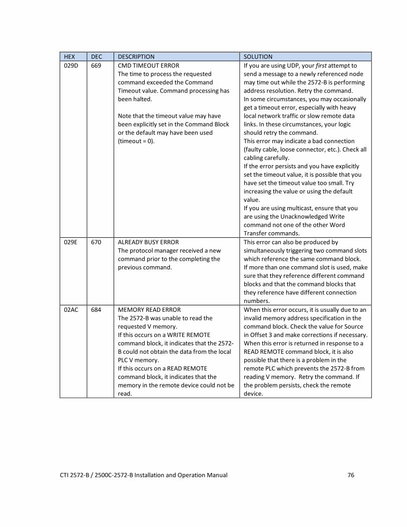
CTI 2572-B / 2500C-2572-B Installation and Operation Manual 76
HEX DEC DESCRIPTION SOLUTION 029D 669 CMD TIMEOUT ERROR
The time to process the requested command exceeded the Command Timeout value. Command processing has been halted. Note that the timeout value may have been explicitly set in the Command Block or the default may have been used (timeout = 0).
If you are using UDP, your first attempt to send a message to a newly referenced node may time out while the 2572-B is performing address resolution. Retry the command. In some circumstances, you may occasionally get a timeout error, especially with heavy local network traffic or slow remote data links. In these circumstances, your logic should retry the command. This error may indicate a bad connection (faulty cable, loose connector, etc.). Check all cabling carefully. If the error persists and you have explicitly set the timeout value, it is possible that you have set the timeout value too small. Try increasing the value or using the default value. If you are using multicast, ensure that you are using the Unacknowledged Write command not one of the other Word Transfer commands.
029E 670 ALREADY BUSY ERROR The protocol manager received a new command prior to the completing the previous command.
This error can also be produced by simultaneously triggering two command slots which reference the same command block. If more than one command slot is used, make sure that they reference different command blocks and that the command blocks that they reference have different connection numbers.
02AC 684 MEMORY READ ERROR The 2572-B was unable to read the requested V memory. If this occurs on a WRITE REMOTE command block, it indicates that the 2572-B could not obtain the data from the local PLC V memory. If this occurs on a READ REMOTE command block, it indicates that the memory in the remote device could not be read.
When this error occurs, it is usually due to an invalid memory address specification in the command block. Check the value for Source in Offset 3 and make corrections if necessary. When this error is returned in response to a READ REMOTE command block, it is also possible that there is a problem in the remote PLC which prevents the 2572-B from reading V memory. Retry the command. If the problem persists, check the remote device.
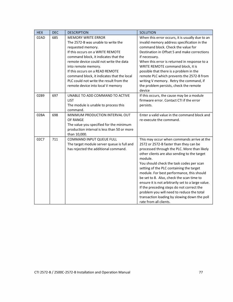
CTI 2572-B / 2500C-2572-B Installation and Operation Manual 77
HEX DEC DESCRIPTION SOLUTION 02AD 685 MEMORY WRITE ERROR
The 2572-B was unable to write the requested memory. If this occurs on a WRITE REMOTE command block, it indicates that the remote device could not write the data into remote memory. If this occurs on a READ REMOTE command block, it indicates that the local PLC could not write the result from the remote device into local V memory
When this error occurs, it is usually due to an invalid memory address specification in the command block. Check the value for Destination in Offset 5 and make corrections if necessary. When this error is returned in response to a WRITE REMOTE command block, it is possible that there is a problem in the remote PLC which prevents the 2572-B from writing V memory. Retry the command, if the problem persists, check the remote device
02B9 697 UNABLE TO ADD COMMAND TO ACTIVE LIST The module is unable to process this command.
If this occurs, the cause may be a module firmware error. Contact CTI if the error persists.
02BA 698 MINIMUM PRODUCTION INTERVAL OUT OF RANGE The value you specified for the minimum production interval is less than 50 or more than 10,000.
Enter a valid value in the command block and re-execute the command.
02C7 711 COMMAND INPUT QUEUE FULL The target module server queue is full and has rejected the additional command.
This may occur when commands arrive at the 2572 or 2572-B faster than they can be processed through the PLC. More than likely other clients are also sending to the target module. You should check the task codes per scan setting of the PLC containing the target module. For best performance, this should be set to 8. Also, check the scan time to ensure it is not arbitrarily set to a large value. If the preceding steps do not correct the problem you will need to reduce the total transaction loading by slowing down the poll rate from all clients.

CTI 2572-B / 2500C-2572-B Installation and Operation Manual 78
HEX DEC DESCRIPTION SOLUTION 02C9 713 UNEXPECTED RESPONSE/BAD EVENT
The Unacknowledged Write command received a response from a CAMP server. You are probably attempting to access a CAMP server that does not support the Unacknowledged Write command. An unexpected event occurred.
If you are accessing a 2572-B, you must have firmware version 2.0 or greater. Using the Web browser interface, check the firmware version. If the version is less than 2.0, upgrade the firmware. If you are accessing a 2572 module, the Unacknowledged Write command is not supported. You must use a 2572_ for this application. If you did not intend to use the Unacknowledged Write command, change the command code. If this does not correct the problem, the cause may be a module firmware error. Contact CTI if the error persists.
Start Network Services Error Codes The following error codes may be returned by the PLC server when it is started using PLC logic.
HEX DEC DESCRIPTION SOLUTION 2370 9072 INVALID OPTION BIT
The option bit setting is invalid when compared to the other parameters in the command block.
Correct the option bit setting or change the conflicting parameters.
2379 9081 INVALID SUBNET MASK The subnet mask that you entered was invalid for the IP address you have assigned to the module. See appendix D.
Correct the subnet mask entry.
2386 9094 INVALID IP ADDRESS The Start Network Services command block does not contain a valid local IP address.
You cannot use a value of 0000 hex or greater than DFFF hex for the IP address. Correct the entry and retry the command.
2387 9095 INVALID PORT NUMBER The Start Network Services command block contains a value of 0 for the PLC server TCP/UDP port number.
You must select a number greater than 0.
2388 9096 INVALID DEFAULT GATEWAY/ROUTER ADDRESS The Start Network Services command block contains an invalid address for the default router.
Correct the entry and retry the command. Note: If you do not have a router on the network, set this value to 0.
238E 9102 INVALID STARTUP OPTIONS The Startup Options word contains an invalid combination of bits.
Correct the command block and re-execute the command.
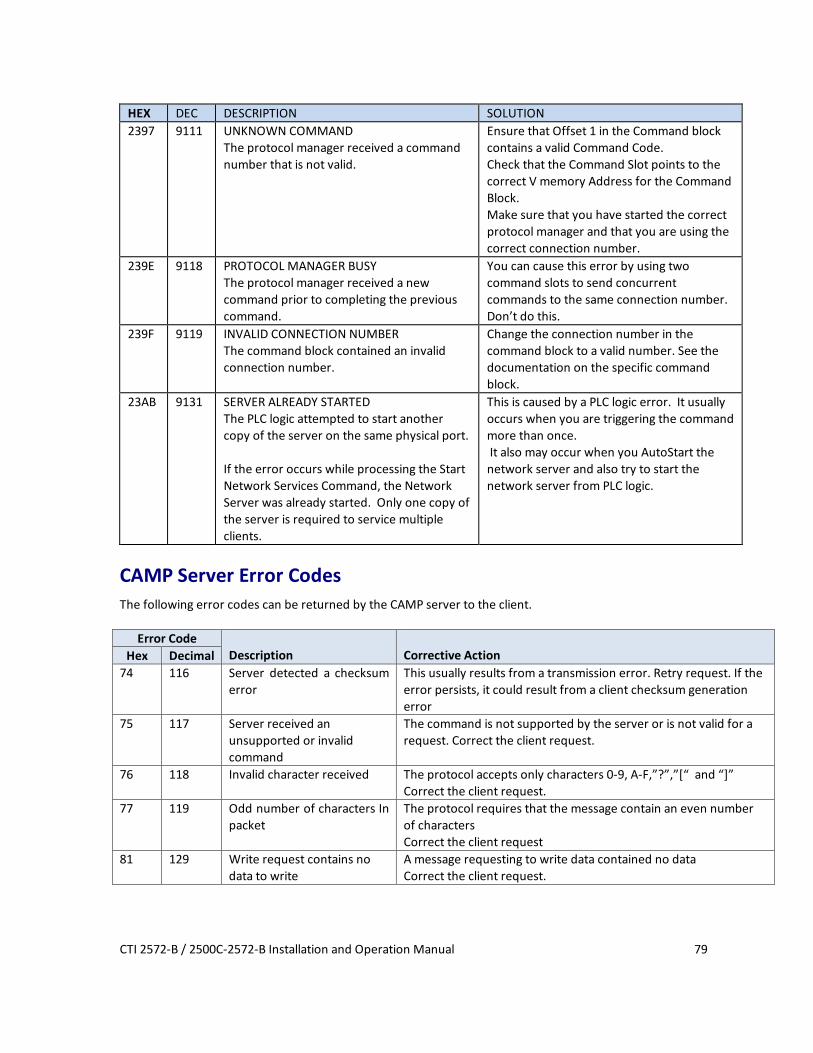
CTI 2572-B / 2500C-2572-B Installation and Operation Manual 79
HEX DEC DESCRIPTION SOLUTION 2397 9111 UNKNOWN COMMAND
The protocol manager received a command number that is not valid.
Ensure that Offset 1 in the Command block contains a valid Command Code. Check that the Command Slot points to the correct V memory Address for the Command Block. Make sure that you have started the correct protocol manager and that you are using the correct connection number.
239E 9118 PROTOCOL MANAGER BUSY The protocol manager received a new command prior to completing the previous command.
You can cause this error by using two command slots to send concurrent commands to the same connection number. Don’t do this.
239F 9119 INVALID CONNECTION NUMBER The command block contained an invalid connection number.
Change the connection number in the command block to a valid number. See the documentation on the specific command block.
23AB 9131 SERVER ALREADY STARTED The PLC logic attempted to start another copy of the server on the same physical port. If the error occurs while processing the Start Network Services Command, the Network Server was already started. Only one copy of the server is required to service multiple clients.
This is caused by a PLC logic error. It usually occurs when you are triggering the command more than once. It also may occur when you AutoStart the network server and also try to start the network server from PLC logic.
CAMP Server Error Codes The following error codes can be returned by the CAMP server to the client.
Error Code Description
Corrective Action Hex Decimal
74 116 Server detected a checksum error
This usually results from a transmission error. Retry request. If the error persists, it could result from a client checksum generation error
75 117 Server received an unsupported or invalid command
The command is not supported by the server or is not valid for a request. Correct the client request.
76 118 Invalid character received The protocol accepts only characters 0-9, A-F,”?”,”[“ and “]” Correct the client request.
77 119 Odd number of characters In packet
The protocol requires that the message contain an even number of characters Correct the client request
81 129 Write request contains no data to write
A message requesting to write data contained no data Correct the client request.

CTI 2572-B / 2500C-2572-B Installation and Operation Manual 80
Error Code
Description Corrective Action Hex Decimal
83 131 Attempted to write to address 0
A message requesting to write data contained an address of 0, which is invalid. Correct the client request.
8F 143 Attempted to read 0 Words A message requesting to read data specified the number of words as 0. Correct the client request.
90 144 Unsupported data element type
The data element type specified in the request message is not supported by the CAMP server. Correct the client request. See APPENDIX C: CAMP SERVER SUPPORT for a list of supported data element types.
91 145 Tried to read more Than 256 words
A CAMP message cannot contain more than 256 words Modify the client to request less data.
93 147 Maximum camp response size exceeded
The resulting size of a reply to a Packed Task Code request would exceed the maximum size of a CAMP message. Correct the client request.
94 148 Maximum packed task code requests exceeded
The number of Packed Task Code requests contained in the CAMP message exceeded the maximum allowed.
95 149 Maximum packed task code length exceeded
The length field of a task code request contained in a CAMP Packed Task code message exceeded the maximum value. Correct the client request
AC 172 Cannot read from memory address
The PLC was unable to read from the requested memory address. This usually occurs when the request exceeds the maximum address available in the PLC. Consider the following corrective actions:
• Change the client request to change the address to be read
• If the client is reading a block of data addresses, ensure that the number of addresses requested does not cause the maximum address to be exceeded.
• Change the PLC memory configuration so that the requested address(es) are available
AD 173 Cannot write to memory address
The PLC was unable to write to the requested memory address. This usually occurs when the request exceeds the maximum address available in the PLC. Consider the following corrective actions:
• Change the client request to change the address to be read
• If the client is reading a block of data addresses, ensure that the number of addresses requested does not cause the maximum address to be exceeded.
• Change the PLC memory configuration so that the requested address(es) are available

CTI 2572-B / 2500C-2572-B Installation and Operation Manual 81
PLC CAMP Client Error Codes
HEX DEC DESCRIPTION SOLUTION 2401 9217 PROTOCOL NOT SUPPORTED
The remote device does not support the IP protocol you are requesting.
The protocol may have been disabled in the startup options of a remote 2572 or 2572-A module. Check the remote device. Check the network address in the command block. If you are using a PC to emulate a PLC server, ensure that the network parameters are properly set.
2402 9218 SOCKET TYPE NOT SUPPORTED The remote device does not support the socket type you are requesting.
See the previous solution.
2403 9219 NETWORK ADDRESS IN USE The 2572-B cannot obtain the network address.
This may occur when there is a general problem on the network. Check the network address you have specified in the command block. Correct if necessary. Retry the operation. If the problem persists contact your network administrator.
2404 9220 CANNOT ASSIGN ADDRESS The 2572-B cannot assign the requested address.
See above. If the problem persists contact CTI.
2405 9221 NETWORK IS DOWN The network you are attempting to use is down.
This may occur when you are attempting to connect to a remote on another network via a router and the network has been taken out of service. First, make sure that you have specified the correct IP address. Retry the operation. If the problem persists, contact your network administrator.
2406 9222 NETWORK IS UNREACHABLE The network you are attempting to use is unreachable.
You have specified a network address for a network that cannot be found. This probably occurred because you specified an incorrect IP network address. Check the entry in the command block and retry. If you believe that you are using the correct network address, contact your network administrator.
2407 9223 NETWORK CONNECTION ABORTED The remote device (host) aborted the connection.
This may occur if the remote host encountered a problem with TCP data transmission where recovery was not possible. You should attempt to create the connection again. If the problem persists, check the remote host.
2408 9224 CONNECTION RESET BY PEER The remote device has reset the connection.
See error code 2407.

CTI 2572-B / 2500C-2572-B Installation and Operation Manual 82
HEX DEC DESCRIPTION SOLUTION 2409 9225 INSUFFICIENT BUFFER SPACE
There is insufficient buffer space to hold the message.
This could occur when the remote host has sent more data than the negotiated buffer space. Retry the operation. If the problem persists, contact CTI.
240A 9226 SOCKET NOT CONNECTED The socket you are attempting to use is not connected to the remote host.
The socket may have been previously disconnected from the remote host work by a network error or because the remote host closed the connection. Create the network connection again and retry.
240B 9227 ATTEMPT TO SEND AFTER SOCKET HAS BEEN SHUT DOWN You are attempting to send data to a socket that has been closed
See above.
240C 9228 CONNECTION TIMED OUT The remote host is not responding to an attempt to connect.
Attempt to create the network connection again. If the problem persists check the status of the remote host. Make sure that all IP addresses are properly set, that the remote host is on line, and that network cables are connected properly.
240D 9229 CONNECTION REFUSED The remote host refused the connection.
If the remote host is a 2572, the maximum number of TCP connections allowed has been exceeded. Wait and try again.
240E 9230 REMOTE HOST IS UNREACHABLE The remote host cannot be found.
This error may occur when the remote host has been taken out of service. It may also occur if you have specified an incorrect IP address.
240F 9231 URGENT DATA RECEIVED The remote host has sent urgent data via TCP. This feature is not supported by the 2572-B.
The remote device has sent you a message format that is not supported. If the remote host is a computer, check to software and network setup. For additional information, see documentation on TCP/IP.
2410 9232 OUT OF BAND DATA RECEIVED You have been sent out of band data via TCP. This feature is not supported by the 2572-B.
See above.
246E 9326 NITP PROTOCOL ERROR When the 2572-B sent an NITP message, the remote device replied with an invalid NITP message. NITP protocol errors include: - Odd number of characters received, - Invalid characters received, - Checksum error, - Incorrect character count field.
This error may occur due to communications error or an improperly programmed remote device. Retry the operation. If the error persists, examine the remote device.
2470 9328 INVALID OPTION BIT VALUE The option bit setting is invalid when compared to the other parameters in the command block.
Correct the option bit setting or change the conflicting parameters. If you are using TCP, you cannot set the IP Address Location bit to 1.

CTI 2572-B / 2500C-2572-B Installation and Operation Manual 83
HEX DEC DESCRIPTION SOLUTION 2473 9331 BAD OR MISSING DELIMITER
The receiving device detected a bad or missing delimiter in the command message
This error usually indicates a transient error in the data link. You should retry the command. If the receiving node is a computer simulating a 2572-B PLC server, ensure that the software is correctly processing the message. If the error persists contact CTI.
2474 9332 BAD BLOCK CHECK CHARACTER The receiving device detected a block check character error in the command message.
See error code 2473
2475 9333 INVALID TYPE The receiving device reported an invalid TYPE character in the message.
See error code 2473.
2476 9334 INVALID DATA CHARACTER The receiving device reported an invalid data character. Only characters 0-9 and A-F are allowed.
See error code 2473.
2477 9335 ODD NUMBER OF CHARACTERS The receiving device reported an odd number of characters in the message. All CAMP messages have an even number of characters.
See error code 2473.
2478 9336 INVALID DEVICE CODE The receiving device reported an invalid device code in the message.
See error code 2473.
247A 9338 INVALID DEVICE CODE The 2572-B detected an invalid device code in the response from the remote device
This error may result from a transient error in the data link. You should retry the command. If the problem persists, check the quality of the data link. If the remote node is a computer simulating a 2572-B PLC server, ensure that the software is correctly creating the response the response message
247B 9339 BAD OR MISSING DELIMITER The 2572-B detected a missing delimiter in the response message
See error code 247A.
247C 9340 BAD BLOCK CHECK CHARACTER The 2572-B found a bad block check character in the response message.
See error code 247A.
247D 9341 INVALID TYPE The 2572-B detected an invalid TYPE character in the message sent from the remote device.
See error code 247A.

CTI 2572-B / 2500C-2572-B Installation and Operation Manual 84
HEX DEC DESCRIPTION SOLUTION 247E 9342 INVALID DATA CHARACTER
The 2572-B detected an invalid data character in the message sent from the remote device. Only characters 0-9 and A-F are allowed.
See error code 247A.
247F 9343 ODD NUMBER OF CHARACTERS The 2572-B detected an odd number of characters in the message sent from the remote device. All CAMP messages have an even number of characters.
See error code 247A.
2480 9344 UNKNOWN ERROR CHARACTER The response contained an unknown error character.
This error is caused by an improperly programmed server node. If the server is a PLC emulating a 2572-B server, review the code and correct as required. If the server is another 2572, contact CTI.
248A 9354 INVALID SERVICE TYPE You specified an invalid value for Type of Service. Must be 1=TCP or 2=UDP.
Correct the value in the Command Block.
248B 9355 INVALID REMOTE IP ADDRESS You specified an invalid value for the remote IP Address.
Correct the value in the Command Block.
2490 9360 INVALID ADDRESS CLASS The address class is not supported by the remote device.
If the server is another 2572, check the firmware version of the module to ensure the latest revision. If the server is a PLC emulating a 2572-B server, review the code and correct as required.
2492 9362 CAMP ID MISMATCH The response did not contain a message ID which matched the command. This can be caused by an improperly programmed remote device. It can also be caused by response delays which exceed the command timeout value. Thus it may be a response to a previous command.
Check the remote device for problems and correct as required. Determine whether you have response delays that exceed the command timeout. You may be able to increase the timeout value so that the command waits longer for a response. You can use network analyzer software to view network traffic. See the Troubleshooting Chapter of this manual.
2497 9367 UNKNOWN COMMAND The protocol manager received a command number which is not valid.
Ensure that Offset 1 in the Command block contains a valid Command Code. Check to be sure that the Command Slot points to the correct V memory Address for the Command Block. Make sure that you have specified the correct protocol manager number in the Create Connection command and that you are using the right connection number.

CTI 2572-B / 2500C-2572-B Installation and Operation Manual 85
HEX DEC DESCRIPTION SOLUTION 249D 9373 CMD TIMEOUT ERROR
The time to process the requested command exceeded the Command Timeout value. Command processing has been halted. Note that the timeout value may have been explicitly set in the Command Block or the default may have been used (timeout = 0).
In some circumstances, you may occasionally get a timeout error, especially with heavy network traffic or remote modem data links. In these circumstances, your logic should retry the command. This error may indicate a bad connection (faulty cable, loose connector, etc.). Check all cabling carefully. If the error persists and you have explicitly set the timeout value, it is possible that you have set the timeout value too small. Try increasing the value or using the default value.
249E 9374 PROTOCOL MANAGER BUSY The protocol manager received a new command prior to completing the previous command.
You can cause this error by using two command slots to send concurrent commands to the same connection number. Don’t do this.
249F 9375 INVALID CLIENT CONNECTION NO. The connection number used during Create Socket was out of the valid range. The valid range of connection numbers is 19221 –19228.
Correct the command block data.
24AC 9388 MEMORY READ ERROR The 2572-B was unable to read the requested V memory.
When this error occurs, it is usually due to an invalid memory address specification in the command block. Check the command block and make corrections if necessary. Check to ensure that the PLC you are addressing is configured for the address you are trying to access.
24AD 9389 MEMORY WRITE ERROR The 2572-B was unable to write to the requested PLC memory.
Check the command block to ensure a valid V memory address has been specified.


CTI 2572-B / 2500C-2572-B Installation and Operation Manual 87
APPENDIX B. PLC COMMAND INTERFACE
General Description CTI 2572-B modules log into the PLC Normal I/O as 2 WX inputs and 6 WY outputs. The PLC controls the module by placing values in specific WY words. The PLC obtains status information from the module via the WX words. Areas of V memory called Command Blocks are used to store command information.
MODULE STATUS WORD
COMMAND STATUS WORD
MODULE CONTROL WORD
COMMAND CONTROL WORD
COMMAND SLOT 1
COMMAND SLOT 2
COMMAND SLOT 3
COMMAND SLOT 4
MODULE WX/ WY COMMANDBLOCKS
WX1
WX2
WY3
WY4
WY5
WY6
WY7
WY8
Command Block 1
Command Block 2
Command Block 3
Command Block 4
Figure 7. PLC Command Interface Figure 7 illustrates the 2572-B PLC Command Interface. The control structures consist of the module WX/WY words and the Command Blocks. Words WY5-WY8 contain the V memory addresses of the command blocks. Using this command interface, the PLC can initiate up to four commands at one time. The status and control bits for the four commands are located in WX2 and WY4, respectively.

CTI 2572-B / 2500C-2572-B Installation and Operation Manual 88
Command Processing Modes You can specify how the module command execution is synchronized with the PLC logic by setting the Command Mode bit in WY4. The Command Mode bit is described in detail later in this appendix. You can select either coupled mode or uncoupled mode. Coupled Mode Processing (One Shot) Coupled Mode provides for tight "handshaking" between the module and the PLC. When the PLC triggers the command, the module will execute the command only once. The module will then wait for acknowledgment from the PLC before allowing the command to be triggered again. Coupled mode is useful for initiating transfers that must be done exactly one time per PLC event (such as Starting the Network Server). Uncoupled Mode Processing (Enable) Uncoupled Mode does not require a handshaking sequence from the PLC. When Uncoupled Mode is selected, the module will read the Command Block when the PLC triggers the command and then execute the command continuously as long as the command trigger is set. Uncoupled mode is useful for providing continuous updates of PLC data.
NOTE: If you make changes to the Command Block, the PLC must clear the command trigger and then
reset it before the new Command Block data will be read.
Command Processing Procedure Following is the typical procedure used to initiate a module command: • Set up the Command Block(s) in V memory using your PLC programming software • Load the command slot(s) with the address of the Command Block(s). • Set the applicable command trigger and mode bits in WY4. • Monitor the status of the command processing using WX2.

CTI 2572-B / 2500C-2572-B Installation and Operation Manual 89
WX/WY Description
Command Status Word
1 2 3 4 5 6 7 8 9 10 11 12 13 14 15 16
Module Status Word
CMD 1Status Bits
WX1
WX2
WY3
WY4
WY5
WY6
WY7
WY8
Command Slot 1: V Memory Address of Command Block for CMD1
Command Slot 2: V Memory Address of Command Block for CMD2
Command Slot 3: V Memory Address of Command Block for CMD3
Command Slot 4: V Memory Address of Command Block for CMD4
CMD 2Status Bits
CMD 3Status Bits
CMD 4Status Bits
Command Control WordCMD 1
Control BitsCMD 2
Control BitsCMD 3
Control BitsCMD 4
Control Bits
Module Control Word
Figure 8. WX/WY Map Figure 8 shows the layout of the WX and WY words assigned to the module. WX1 and WY3 are used for global module control and status. The remaining words are used for command processing. Note there are four command slots, which allows the PLC to trigger up to four module commands in one scan. The four sets of bits in WX2 and WY4 correspond to the four command slots.

CTI 2572-B / 2500C-2572-B Installation and Operation Manual 90
Module Status Word The Module Status Word (WX1) is used to communicate the overall status of the module. The module uses the following bit structure:
1 2 3 4 5 6 7 8-15 16 MOD STATUS
RSVD NET CFG
RSVD RSVD LS PWR RSVD HEART BEAT
Bit 1 - MOD STATUS - Module Status This bit is set to 1 whenever the application firmware OK and the network server is started.
Bit 2 –RSVD – Reserved
This bit is reserved for future use.
Bit 3 -NET CFG - Network Configuration Required This bit is set by the module application code to indicate that the network CAMP server has not been started. The primary use of this bit is to condition PLC ladder logic to trigger the START
NETWORK SERVICES command. When the PLC Start option is selected, this bit is set to a value of 1 at startup. When the CAMP network server has successfully started, this bit is set to a value of 0.
Bit 4 and 5– RSVD - Reserved These bit positions are reserved for future use.
Bit 6 – LS - Link Status This bit indicates the status of the Ethernet Link. It is set to a value of 1 when the Ethernet port is connected to a functioning Ethernet switch or device. Otherwise is set to a value of 0.
Bit 7- PWR – Low Power This bit allows the PLC to monitor backplane power. It is set whenever backplane power drops below the minimum acceptable voltage (4.75 V) and cleared when the voltage is back in range.
Bit 8 – 15 RSVD - Reserved These bit positions are reserved for future use. Bit 16 - HEARTBEAT- Heartbeat The module toggles this bit between 1 and 0 approximately once per second. It is used as an indication that the module software is functioning.
Module Control Word (WY3) The Module Control Word allows the PLC to control global module operation. Currently, there is only one control option, to reset the module.
1 2 3 4 5 6 7 8 9 10 11 12 13 14 15 16
MOD RST
Module Control Bits are contained in WY3. Bit 1 is a module reset bit. When the bit is set and all four abort triggers are set in the Command Control Word, the module will perform a hardware reset. This operation resets the processor and initiates a complete module restart. It is available for extreme error cases where simply acknowledging an error or aborting a command does not clear the error.
Command Control and Command Status Words The command status word and the command control word contain bits that are used to synchronize and control the execution of module commands. The Command Control Word is located in module word WY4 and

CTI 2572-B / 2500C-2572-B Installation and Operation Manual 91
contains bits that are set by the PLC logic. The Command Status Word is located in WX2 and contains bits that are set by the module. Since the PLC can send up to four commands to the module per scan, both the Command Control Word and the Command Status Word contain four sets of bits, one set for each possible concurrent command. For example, the first four bits (bits 1-4) in both words relate to command Slot 1, the next four bits (bits 5-8) relate to command Slot 2, etc. The four command slots execute commands independently. Thus, an error on one command does not affect processing on the other commands than happen to be executing at the same time. The command slots can be triggered at different times or all may be triggered concurrently.
Command Control Word The Command Control Word contains bits that are set by the PLC logic. The following illustration indicates how the bits within the word are used. COMMAND CONTROL WORD (WY4)
1 2 3 4 5 6 7 8 9 10 11 12 13 14 15 16
ERR Ack
CMD Mode
CMD Trig
Abort Trig
ERR Ack
CMD Mode
CMD Trig
Abort Trig
ERR Ack
CMD Mode
CMD Trig
Abort Trig
ERR Ack
CMD Mode
CMD Trig
Abort Trig
Command 1 Command 2 Command 3 Command 4
ERROR Ack Error Acknowledge. The PLC sets this bit to acknowledge the error bit which was set by the 2572.
CMD Mode Command Mode. The PLC sets this bit to control how the module command execution is synchronized with the PLC logic: 0 = Uncoupled mode - The 2572-B command processing is not synchronized with the PLC logic. 1 = Coupled mode - The 2572-B command processing is synchronized with the PLC logic.
CMD Trig Command Trigger. The PLC sets this bit to initiate a command.
ABORT Trig Abort Trigger. The PLC sets this bit to abort a command in progress. In most cases, use of the abort bit is not required, since the command executes to completion, either successfully or with error.

CTI 2572-B / 2500C-2572-B Installation and Operation Manual 92
Command Status Word The Command Status Word contains bits that are set by the module. The following illustration indicates how the bits within the word are used. COMMAND STATUS WORD (WX2)
1 2 3 4 5 6 7 8 9 10 11 12 13 14 15 16
CMD Err
PLC Err
CMD Busy
Abrt Busy
CMD Err
PLC Err
CMD Busy
Abrt Busy
CMD Err
PLC Err
CMD Busy
Abrt Busy
CMD Err
PLC Err
CMD Busy
Abrt Busy
Command 1 Command 2 Command 3 Command 4
CMD Err Command Error. The 2572-B sets this bit when it encounters an error while attempting to execute the command. The 2572-B will write an error code into Offset 0 of the command block unless PLC ERR is also set (see below).
PLC Err PLC Read/Write Error. The 2572-B sets this bit to indicate that it could not read a valid command block from V memory. Therefore, there is no place to write an error word. This may be caused by loading a value in the Command Slot which is not a valid V memory location (such as 0) or which points to V memory that does not contain a Command Block.
CMD Busy Indicates the module is in the process of executing a command.
ABORT Busy Indicates the module is attempting to abort a command.
Command Slots (WY5-WY8) Module words WY5, WY6, WY7, and WY8 are called Command Slots. There are four command slots, one for each possible concurrent command. The value in the command slot points to the V memory address of a command block as illustrated below. Addresses of 0 or less are invalid. Addresses greater than 64k cannot be referenced. COMMAND SLOTS
WY5 Command Slot 1: V Memory Address of Command Block for CMD1 WY6 Command Slot 2: V Memory Address of Command Block for CMD2 WY7 Command Slot 3: V Memory Address of Command Block for CMD3 WY8 Command Slot 4: V Memory Address of Command Block for CMD4
Note that the command slots match up with the command control and command status bits in WY4 and WX2. For example, the command block whose address in Command Slot 1 will be triggered by setting bit 3 in WY4 (Bit 3 is the Command Trigger for Command 1).

CTI 2572-B / 2500C-2572-B Installation and Operation Manual 93
WX2 and WY4 Relationships The following illustrates the relationship between the first four bits in WX2 and WY4. This relationship applies to the other three sets of bits.
Word Bit 1 Bit 2 Bit 3 Bit 4 WX2 CMD Err PLC Err CMD Busy Abort Busy WY4 ERR Ack CMD Mode CMD Trigger Abort Trigger
Error Processing Bits The module will set CMD ERR any time an error occurs in processing a command. The module will also set PLC
ERR if a valid Command Block cannot be read from V memory. After setting the error bits, the module will halt processing on this command. The PLC acknowledges the error by setting ERR ACK. When the module sees ERR
ACK go high, it aborts the command, clears the error bits, and is ready to accept another command trigger for this slot.
Command Processing Bits The PLC sets the CMD MODE bit to select whether Coupled Mode or Uncoupled Mode is used. The PLC sets the CMD TRIGGER to initiate the command. When the module begins command processing, it sets the CMD
BUSY bit. The CMD BUSY bit will remain on until the module has completed processing the command.
Abort Processing Bits The PLC can set the ABORT TRIGGER to request the module to abort a command that is in process. When the module starts the process of aborting a command, it raises the ABORT BUSY bit. When the process is complete, it lowers ABORT BUSY (and also CMD BUSY). The timing diagrams in this appendix describe the interaction of the various Command Control and Command Status bits.

CTI 2572-B / 2500C-2572-B Installation and Operation Manual 94
WX/WY Quick Reference
PWR

CTI 2572-B / 2500C-2572-B Installation and Operation Manual 95
Command Blocks Command Blocks contain information which specifies how the command is to be executed. The standard Command Block consists of 16 contiguous words located in the first 64k of PLC V memory and has the following general structure.
Offset Contents 0 Error Word 1 Command Code 2 Connection Number 3 Command Parameter 1 4 - 15 Additional parameters
Error Word Assuming the Command Block is valid, the module will write an error code into this location
when it encounters an error in executing the command. The error code can be used during development as an aid to de-bugging logic. It may also be used by the PLC logic as an indication to execute specific error processing logic.
Command Code
The Command Code is a number which uniquely defines the command you wish to execute.
Connection Number
The connection number identifies the instance of the protocol manager with which you are communicating. A connection number is similar to a file handle used in other operating environments. The connection number is established when a CREATE CONNECTION or CREATE
SOCKET command is executed. During this process, a specific protocol manager is loaded and associated with a particular physical port or a network socket. If the connection is created using PLC logic, the programmer can assign a connection number. If the connection is automatically created by the module, the module will assign a connection number. The high byte of the Connection number should always contains hex 4B. The module uses this byte as a Command Block "signature". The use of the signature byte provides a way for the module to verify that the address you loaded in the command slot indeed points to a valid command block and not some arbitrary area of V memory. When the module detects that you have referenced an area of V memory where the high byte of offset 3 does not contain hex 4B, it asserts the CMD Err and PLC Err. Since the module assumes that a block without a signature byte is not a command block but a reference error, it does not attempt to process the block of V memory and does not write any error information back into offset 0 of the block.
Command Parameters
The command parameters provide command execution information. For example, for a Read Command they may specify where to obtain the data, how many words to read, and where to store the results. The number of command parameters required will vary with different commands.

CTI 2572-B / 2500C-2572-B Installation and Operation Manual 96
Command Timing Diagrams The following diagrams illustrate how the command trigger bits and the command status bits interact.
Coupled (One Shot) Mode Timing (CMD Mode Bit = 1)
Figure 9. Coupled Mode Timing Coupled (One Shot) Mode should be selected when you want to ensure that the module will execute a command only once per trigger. In Coupled Mode the PLC and the module use the CMD TRIG (Command Trigger) and the CMD BUSY (Command Busy) bits in a "handshaking" sequence. The following figure illustrates the timing relationships between CMD TRIG and CMD BUSY for a Coupled Mode command. The PLC has cleared CMD TRIG (Time A) and the module has cleared CMD BUSY (Time B) indicating that the processing of the previous command is complete. At Time C, the PLC asserts CMD TRIG to initiate a command. When the module recognizes that CMD TRIG is high, it asserts CMD BUSY (Time D) and samples the CMD MODE bit to determine the command mode. It then retrieves the command block and starts processing the command. Any time after the PLC sees CMD BUSY go high, it may lower CMD TRIG (Time E). Once the module completes processing the command, it samples CMD TRIG. If CMD TRIG is off, the Module will lower CMD BUSY (Time F) and wait for the next trigger. If CMD TRIG is on, the module will hold busy high and wait until CMD TRIG is turned off. Time F will be delayed as required until CMD TRIG is off. At time F (equivalent to time B), both CMD TRIG and CMD BUSY are low and a new cycle can begin whenever the PLC asserts CMD TRIG.

CTI 2572-B / 2500C-2572-B Installation and Operation Manual 97
NOTE:
The Command Block is subject to access and change by the module any time after CMD TRIG is asserted (time C) until CMD BUSY is cleared (time F). Thus, the Command Block should not be
changed by the PLC at any time between time C and F.
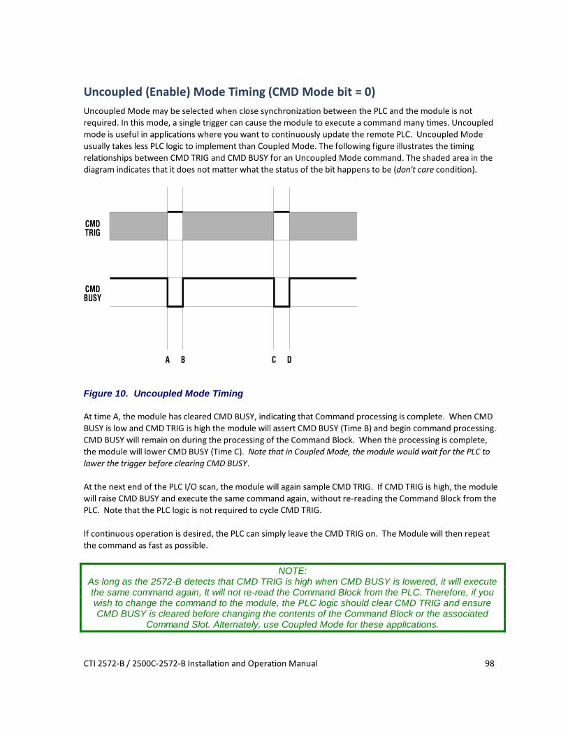
CTI 2572-B / 2500C-2572-B Installation and Operation Manual 98
Uncoupled (Enable) Mode Timing (CMD Mode bit = 0) Uncoupled Mode may be selected when close synchronization between the PLC and the module is not required. In this mode, a single trigger can cause the module to execute a command many times. Uncoupled mode is useful in applications where you want to continuously update the remote PLC. Uncoupled Mode usually takes less PLC logic to implement than Coupled Mode. The following figure illustrates the timing relationships between CMD TRIG and CMD BUSY for an Uncoupled Mode command. The shaded area in the diagram indicates that it does not matter what the status of the bit happens to be (don't care condition).
Figure 10. Uncoupled Mode Timing At time A, the module has cleared CMD BUSY, indicating that Command processing is complete. When CMD BUSY is low and CMD TRIG is high the module will assert CMD BUSY (Time B) and begin command processing. CMD BUSY will remain on during the processing of the Command Block. When the processing is complete, the module will lower CMD BUSY (Time C). Note that in Coupled Mode, the module would wait for the PLC to lower the trigger before clearing CMD BUSY. At the next end of the PLC I/O scan, the module will again sample CMD TRIG. If CMD TRIG is high, the module will raise CMD BUSY and execute the same command again, without re-reading the Command Block from the PLC. Note that the PLC logic is not required to cycle CMD TRIG. If continuous operation is desired, the PLC can simply leave the CMD TRIG on. The Module will then repeat the command as fast as possible.
NOTE: As long as the 2572-B detects that CMD TRIG is high when CMD BUSY is lowered, it will execute the same command again, It will not re-read the Command Block from the PLC. Therefore, if you wish to change the command to the module, the PLC logic should clear CMD TRIG and ensure CMD BUSY is cleared before changing the contents of the Command Block or the associated
Command Slot. Alternately, use Coupled Mode for these applications.

CTI 2572-B / 2500C-2572-B Installation and Operation Manual 99
Command Error Timing The module provides a mechanism for command execution communicating errors to the PLC. This is accomplished via the CMD ERR bit and the ERROR WORD in the Command Block. The following figure illustrates Command Error timing. Note that the shaded area indicates a "don't care" condition for the particular bit.
Figure 11. Command Error Timing At time A, the module has set CMD BUSY and is attempting to retrieve the command block and to process the command.
Sometime later, a command processing error occurs. The module writes error information into the error word of the Command Block and asserts CMD ERR at time B. Processing of this command is halted.
If the module cannot write the error word to the Command Block, it also asserts the PLC ERR bit (see the following section). The error word is valid only when CMD error is asserted and PLC ERR is clear.
At the end of each PLC I/O scan, the module samples the state of ERROR ACK (Error Acknowledge). As soon as the module detects that ERROR ACK is set (Time C), it will turn off CMD ERR (and PLC ERR if on) at Time D and proceed with the error recovery.
After error recovery is completed, the module will clear CMD BUSY (Time E). This may or may not be the in the same PLC I/O scan. CMD ERR will never be asserted unless CMD BUSY is asserted. CMD ERR is always cleared prior to or at the same time as the release of the CMD BUSY signal (Time D is always before or the same as time E).
NOTE: The contents of the error word in the Command Block are valid only when CMD ERR is asserted
and PLC ERR is clear. Since the ERROR ACK signal is sampled only when CMD ERR or PLC ERR is asserted, PLC logic can leave the ERROR ACK bit on, if you wish to ignore all errors.

CTI 2572-B / 2500C-2572-B Installation and Operation Manual 100
PLC Error Timing A PLC error occurs when the module cannot read a valid Command Block from the PLC V memory or it cannot write back to this location. The following diagram illustrates timing for the PLC ERR bit. Note that the shaded area indicates a "don't care" condition for the particular bit.
Figure 12. PLC Error Timing At time A, the module has set CMD BUSY and attempts to retrieve the command block from V memory. At time B, the module determines it cannot retrieve a valid command block and asserts the CMD ERR and the PLC ERR bit. Since a valid command cannot be retrieved, the module halts processing of this command. At time C the module samples the ERROR ACK bit and determines that it is asserted, indicating that the PLC has acknowledged the error. Sometime later the module clears the CMD ERR and PLC ERR bits (Time D) and the CMD BUSY bit (Time E). The error bits will always be cleared prior to or at the same time as CMD BUSY. Note that, in this example, no error code is written to the command block. Since a Command Block could not be read, the module does not attempt to write an error code into the V memory location indicated in the command slot.
NOTE: When the PLC ERR bit is set, it is almost always the result of:
1) An invalid address in the Command Slot (WY5, WY6, WY7, or WY8) or 2) A command block connection number that does not have hex 4B in the high byte
If the PLC ERR bit is on, you should check your PLC logic carefully!

CTI 2572-B / 2500C-2572-B Installation and Operation Manual 101
Command Abort Timing There may be rare occasions when you need to abort a command that is in progress. For example, if you triggered a READ REMOTE command with an infinite timeout and the data was never returned, the protocol manager would wait forever, blocking further execution in the command slot. Figure 13 illustrates abort timing.
Figure 13. Command Abort Timing Assume the module is busy processing a command (Time A). At time B, the PLC asserts ABORT TRIG to stop the ongoing command processing. When the module recognizes that ABORT TRIG is high, the module will assert ABORT BUSY (Time C).
After detecting ABORT BUSY, the PLC should clear ABORT TRIG (Time D). When the Module has completed abort processing, it clears ABORT BUSY (Time E).
After ABORT BUSY is cleared, the module will clear CMD BUSY (Time F). Time F may be on the same scan or on a later scan than time D. ABORT BUSY will never be asserted unless CMD BUSY is also asserted.
NOTE: ABORT BUSY will be cleared even if the ABORT TRIG is still active. If the PLC does not clear
ABORT TRIG, no further commands will be processed for the Command slot. Depending upon the nature of the command and circumstances of execution, some commands cannot be aborted.
NOTE: Setting all four abort triggers and asserting the module reset bit in WY3 will cause the module to
perform a complete reset.

CTI 2572-B / 2500C-2572-B Installation and Operation Manual 102
General Command Considerations When designing your PLC logic you should be aware of the following:
• The Command Trigger is ignored for a command if the associated Abort Trigger is set.
• In Uncoupled Mode, the PLC may not see CMD BUSY go low in between command cycles. After you lower the trigger, the module may execute the command additional times.
• If ERR ACK is set and left high, the associated CMD ERR bit may be set and cleared without the PLC detecting it.
• With the notable exception of Module Reset (all four abort triggers are set along with the module reset bit) the command slots are totally independent. Unless the commands are directed to a common resource, the command slots should have no effect on each other.

CTI 2572-B / 2500C-2572-B Installation and Operation Manual 103
APPENDIX C. IP ADDRESS INFORMATION
IP Address Nomenclature
IP Address Every host interface on a TCP/IP network is identified by a unique IP address. This address is used to uniquely identify the host device, such as a workstation or communications module, and the network to which the host belongs. Each IP address consists of 32 bits, divided into four 8 bit entities called octets. An IP address is expressed in dotted notation, with each octet expressed as its decimal equivalent. See the example below.
Notation Octet 1 Octet 2 Octet 3 Octet 4 Binary 11000000 11011111 10110001 00000001 Decimal 192 223 177 1
Although an IP address is a single value, it contains two types of information: the Network ID and the Host ID. The Network ID identifies the IP network to which the host belongs. The Host ID identifies a specific IP host on that IP network. All IP hosts on a particular local area network must have the same network ID. Each IP host on a particular local area network must use a unique Host ID.
Address Classes The Internet community originally defined network classes to accommodate networks of varying sizes. The network class can be determined from the first octet of its IP address. The following table summarizes the relationship between the first octet of a given address and its Network ID and Host ID fields. It also identifies the total number of Network IDs and Host IDs for each address class that participates in the Internet addressing scheme. Class First Octet
Value* Network ID Host ID Number of
networks Number of hosts per net
A 1-126 First Octet Last 3 Octets 126 16,777,214 B 128-191 First 2 Octets Last 2 Octets 16,384 65,534 C 192-223 First 3 Octets Last Octet 2,097,151 254 * Address 127 is reserved for loopback testing and inter-process communication on the local computer; it is not a valid network address. Addresses 224 – 239 are used for Class D (IP multicast).

CTI 2572-B / 2500C-2572-B Installation and Operation Manual 104
Subnet Mask The designation of network classes proved to be very inflexible. For example, a Class A network assigned a large number of host devices to the same IP network; potentially reducing performance, limiting topology, and compromising network security. An additional entity, the Subnet Mask, was introduced to allow segmenting an IP network into a collection of smaller networks called subnets. The Subnet Mask is a collection of 32 bits that distinguish the network ID portion of the IP address from the host ID. Subnet mask bits that belong to the network ID are set to 1. Subnet Mask bits that belong to the host ID are set to 0. To represent the mask, the 32-bit value is converted to dotted decimal notation or to CIDR (Classless Inter-Domain Routing) notation. The CIDR notation is a modern alternative which counts the number of bits in Network ID portion of the address (bits that are set to 1). The count is preceded by a slash. See the example below. Bits for Network Mask Dotted Decimal Format CIDR Format 11111111 00000000 00000000 00000000 255.0.0.0 /8 11111111 11111111 11110000 00000000 255.255.240.0 /20 11111111 11111111 11111111 00000000 255.255.255.0 /24
NOTE The binary representation of a Network Mask must be a single continuous block 1’s followed by a
contiguous block of zeroes. When entering the Network Mask in dotted decimal notation, you must ensure that this requirement is maintained. For example, a network mask of 255.247.0.0 is not valid
because the binary equivalent (11111111111101110000000000000000) violates this rule. The Network Mask must allow at least two bits of host address. In addition, a network mask which causes the derived host ID to be 0 or a broadcast address (all Host ID bits set to 1) should not be used.
Using the Subnet Mask The transmitting IP Host uses the Subnet Mask to determine where to send an IP message that has a unicast IP address. After deriving the Network ID and Host ID portion of the IP Address using the Subnet Mask, the IP Host compares the Network ID of the destination IP address with the Network ID of the Host IP address. If the Network IDs are the same, the message is sent to another Host on the local network. If the Network IDs are different, the message is sent to an IP Gateway, for routing to another network, if possible. When you are configuring the IP address of devices that must communicate on the local network, you must ensure that:
• The Subnet Mask of all devices are the same, • The Network ID of all hosts are the same, • The Host ID of each host is different.
If you are using subnet masks that are aligned with the IP address octets, this can easily be done by examining the dotted decimal values. The octets of the IP address where the corresponding octet of the subnet mask is 255 belong to the Network ID and the octets of the IP address where the corresponding octet of the subnet mask is 0 belong to the Host ID.

CTI 2572-B / 2500C-2572-B Installation and Operation Manual 105
For example, where the IP address is 126.18.40.3 with a subnet mask of 255.255.0.0, the Network ID is 126.18 and the Host ID is 40.3.
IP Address 126 18 40 3 Subnet Mask 255 255 0 0 Network ID 126 18 Host ID 40 3
However, if you are using a subnet mask that does not align with the octet boundaries, this is more difficult. You will need to perform a bitwise “and” calculation to arrive at the Network address. See the following illustration. Assuming an IP address of 127.18.40.3 and a Subnet Mask of 255.255.240.0, the following table illustrates the bitwise “and” operation. In essence, wherever the subnet mask bit is one, the corresponding IP address bit is part of the Network ID.
Item Dotted Decimal
Binary Equivalent 1st Octet 2nd Octet 3rd Octet 4th Octet
IP Address 127.18.40.3 01111111 00010010 00101000 00000011
Subnet Mask 255.255.240.0
11111111 11111111 11110000 00000000
Derived Network Address
127.18.32.0 01111111 00010010 00100000 00000000
An easier way to determine this is to compare only non-aligned subnet mask octet with the corresponding octet of the IP address. For example, since the subnet mask of the first two octets is 255.255, the first two octets of the Network ID are the same as the dotted decimal values (127.18) of the IP address. However, since the third octet of the subnet mask is not 255 or 0, you must perform a bitwise calculation using the third octet of the IP address and network mask. The can be accomplished this is to use the windows calculator (Scientific View in Windows XP or Programmer view in Windows 7). Using this example, you would enter the value of the third octet (40), click on the “and” button, enter the subnet mask (240), and then click on the “=” button. The result, in this case, is 32. Thus the Network address is 127.18.32.0.
NOTE The binary representation of a Network Mask must be a single continuous block 1’s followed by a
contiguous block of zeroes. When entering the Network Mask in dotted decimal notation, you must ensure that this requirement is maintained. For example, a network mask of 255.247.0.0 is not valid
because the binary equivalent (11111111111101110000000000000000) violates this rule. The Network Mask must allow at least two bits of host address. In addition, a network mask which causes the derived host ID to be 0 or a broadcast address (all Host ID bits set to 1) should not be used.
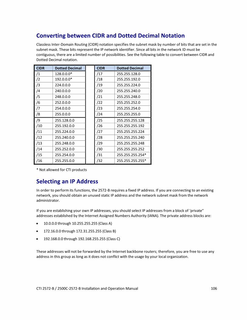
CTI 2572-B / 2500C-2572-B Installation and Operation Manual 106
Converting between CIDR and Dotted Decimal Notation Classless Inter-Domain Routing (CIDR) notation specifies the subnet mask by number of bits that are set in the subnet mask. These bits represent the IP network identifier. Since all bits in the network ID must be contiguous, there are a limited number of possibilities. See the following table to convert between CIDR and Dotted Decimal notation.
CIDR Dotted Decimal CIDR Dotted Decimal /1 128.0.0.0* /17 255.255.128.0 /2 192.0.0.0* /18 255.255.192.0 /3 224.0.0.0 /19 255.255.224.0 /4 240.0.0.0 /20 255.255.240.0 /5 248.0.0.0 /21 255.255.248.0 /6 252.0.0.0 /22 255.255.252.0 /7 254.0.0.0 /23 255.255.254.0 /8 255.0.0.0 /24 255.255.255.0 /9 255.128.0.0 /25 255.255.255.128 /10 255.192.0.0 /26 255.255.255.192 /11 255.224.0.0 /27 255.255.255.224 /12 255.240.0.0 /28 255.255.255.240 /13 255.248.0.0 /29 255.255.255.248 /14 255.252.0.0 /30 255.255.255.252 /15 255.254.0.0 /31 255.255.255.254* /16 255.255.0.0 /32 255.255.255.255*
* Not allowed for CTI products
Selecting an IP Address In order to perform its functions, the 2572-B requires a fixed IP address. If you are connecting to an existing network, you should obtain an unused static IP address and the network subnet mask from the network administrator. If you are establishing your own IP addresses, you should select IP addresses from a block of ‘private” addresses established by the Internet Assigned Numbers Authority (IANA). The private address blocks are:
• 10.0.0.0 through 10.255.255.255 (Class A)
• 172.16.0.0 through 172.31.255.255 (Class B)
• 192.168.0.0 through 192.168.255.255 (Class C)
These addresses will not be forwarded by the Internet backbone routers; therefore, you are free to use any address in this group as long as it does not conflict with the usage by your local organization.

CTI 2572-B / 2500C-2572-B Installation and Operation Manual 107
Selecting a Multicast Address The IPV4 address range of 224.0.0.1 – 239.255.255.255 has been reserved for IP multicast. Multicast allows a one to many relationship, where a single message can be processed by multiple recipients. Unlike a broadcast message, which is received by all IP hosts on an Ethernet network segment, a message with a specific multicast destination address will be admitted only by IP hosts that are listening to this address. IANA, the Internet Assigned Numbers Authority, has designated blocks of addresses within the IPV4 multicast range for specific purposes, such as local and internetwork control. The address range of 239.0.0.0 – 239.255.255.255 has been designated as an administratively scoped Multicast address space (RFC 2365). Addresses in this range are designated for use by private multicast domains. They do not conflict with other multicast address spaces that are explicitly assigned by IANA. Within this range, addresses 239.255.0.0 – 239.255.255.255 is designated for the IPV4 multicast local scope, which includes multicast limited to a particular local area network. If you are choosing a multicast address for a new factory floor application, you should choose a multicast address in the IPV4 local scope range (239.255.0.0 – 239.255.255.255) unless you have a specific reason to do otherwise. When choosing a multicast address, you should verify there is no conflict with other multicast addresses being used locally.
NOTE: The 2572-B implementation of UDP Multicast requires that all participating hosts be on the same
Ethernet local area network. Routing of multicast packets is not supported. In case you are using the 2572-B module in an existing multicast application that uses a multicast address outside of the administratively scoped address space, the 2572-B web server page and PLC logic interface allows you to enter the complete range of assignable multicast addresses (224.0.0.1 – 239.255.255.255). .


CTI 2572-B / 2500C-2572-B Installation and Operation Manual 109
HARDWARE SPECIFICATIONS
Module Size: Single Wide 505 I/O Backplane Power Consumption: 2.8 watts @ 5 VDC Operating Temperature: 0º to 60º C (32º to 185º F) Storage Temperature: -40º to 85º C (-40º to 185º F) Humidity: 0% to 95%, non-condensing

CTI 2572-B / 2500C-2572-B Installation and Operation Manual 110
LIMITED PRODUCT WARRANTY
Control Technology Inc. ("CTI") warrants that this CTI Industrial Product (the "Product") shall be free from defects in material and workmanship for a period of one (1) year from the date of purchase from CTI or from an authorized CTI Industrial Distributor, as the case may be. Repaired or replacement CTI products provided under this warranty are similarly warranted for a period of 6 months from the date of shipment to the customer or the remainder of the original warranty term, whichever is longer. This Product and any repaired or replacement products will be manufactured from new and/or serviceable used parts which are equal to new in the Product. This warranty is limited to the initial purchaser of the Product from CTI or from an authorized CTI Industrial Distributor and may not be transferred or assigned.
2. Remedies. Remedies under this warranty shall be limited, at CTI's option, to the replacement or repair of this Product, or the parts thereof, only after shipment by the customer at the customer's expense to a designated CTI service location along with proof of purchase date and an associated serial number. Repair parts and replacement products furnished under this warranty will be on an exchange basis and all exchanged parts or products become the property of CTI. Should any product or part returned to CTI hereunder be found by CTI to be without defect, CTI will return such product or part to the customer. The foregoing will be the exclusive remedies for any breach of warranty or breach of contract arising therefrom.
3. General. This warranty is only available if (a) the customer provides CTI with written notice of a warranty claim within the warranty period set forth above in Section 1 and (b) CTI's examination of the Product or the parts thereof discloses that any alleged defect has not been caused by a failure to provide a suitable environment as specified in the CTI Standard Environmental Specification and applicable Product specifications, or damage caused by accident, disaster, acts of God, neglect, abuse, misuse, transportation, alterations, attachments, accessories, supplies, non-CTI parts, non-CTI repairs or activities, or to any damage whose proximate cause was utilities or utility-like services, or faulty installation or maintenance done by someone other than CTI.
4. Product Improvement. CTI reserves the right to make changes to the Product in order to improve reliability, function or design in the pursuit of providing the best possible products.
5. Exclusive Warranty. THE WARRANTIES SET FORTH HEREIN ARE CUSTOMER'S EXCLUSIVE WARRANTIES. CTI HEREBY DISCLAIMS ALL OTHER WARRANTIES, EXPRESS OR IMPLIED. WITHOUT LIMITING THE FOREGOING, CTI SPECIFICALLY DISCLAIMS THE IMPLIED WARRANTIES OF MERCHANTABILITY, FITNESS FOR A PARTICULAR PURPOSE, NON-INFRINGEMENT, COURSE OF DEALING, AND USAGE OF TRADE.
6. Disclaimer and Limitation of Liability. TO THE FULLEST EXTENT PERMITTED BY APPLICABLE LAW, CTI WILL NOT BE LIABLE FOR ANY BUSINESS INTERRUPTION OR LOSS OF PROFIT, REVENUE, MATERIALS, ANTICIPATED SAVINGS, DATA, CONTRACT, GOODWILL OR THE LIKE (WHETHER DIRECT OR INDIRECT IN NATURE) OR FOR ANY OTHER FORM OF INCIDENTAL, INDIRECT OR CONSEQUENTIAL DAMAGES OF ANY KIND. CTI'S MAXIMUM CUMULATIVE LIABILITY RELATIVE TO ALL OTHER CLAIMS AND LIABILITIES, INCLUDING OBLIGATIONS UNDER ANY INDEMNITY, WHETHER OR NOT INSURED, WILL NOT EXCEED THE COST OF THE PRODUCT(S) GIVING RISE TO THE CLAIM OR LIABILITY. CTI DISCLAIMS ALL LIABILITY RELATIVE TO GRATUITOUS INFORMATION OR ASSISTANCE PROVIDED BY, BUT NOT REQUIRED OF CTI HEREUNDER. ANY ACTION AGAINST CTI MUST BE BROUGHT WITHIN EIGHTEEN (18) MONTHS AFTER THE CAUSE OF ACTION ACCRUES. THESE DISCLAIMERS AND

CTI 2572-B / 2500C-2572-B Installation and Operation Manual 111
LIMITATIONS OF LIABILITY WILL APPLY REGARDLESS OF ANY OTHER CONTRARY PROVISION HEREOF AND REGARDLESS OF THE FORM OF ACTION, WHETHER IN CONTRACT, TORT (INCLUDING NEGLIGENCE AND STRICT LIABILITY) OR OTHERWISE, AND FURTHER WILL EXTEND TO THE BENEFIT OF CTI'S VENDORS, APPOINTED DISTRIBUTORS AND OTHER AUTHORIZED RESELLERS AS THIRD-PARTY BENEFICIARIES. EACH PROVISION HEREOF WHICH PROVIDES FOR A LIMITATION OF LIABILITY, DISCLAIMER OF WARRANTY OR CONDITION OR EXCLUSION OF DAMAGES IS SEVERABLE AND INDEPENDENT OF ANY OTHER PROVISION AND IS TO BE ENFORCED AS SUCH.
7. Adequate Remedy. The customer is limited to the remedies specified herein and shall have no others for a nonconformity in the Product. The customer agrees that these remedies provide the customer with a minimum adequate remedy and are its exclusive remedies, whether based on contract, warranty, tort (including negligence), strict liability, indemnity, or any other legal theory, and whether arising out of warranties, representations, instructions, installations, or non-conformities from any cause. The customer further acknowledges that the purchase price of the Product reflects these warranty terms and remedies.
8. Force Majeure. CTI will not be liable for any loss, damage or delay arising out of its failure (or that of its subcontractors) to perform hereunder due to causes beyond its reasonable control, including without limitation, acts of God, acts or omissions of the customer, acts of civil or military authority, fires, strikes, floods, epidemics, quarantine restrictions, war, riots, acts of terrorism, delays in transportation, or transportation embargoes. In the event of such delay, CTI's performance date(s) will be extended for such length of time as may be reasonably necessary to compensate for the delay.
9. Governing Law. The laws of the State of Tennessee shall govern the validity, interpretation and enforcement of this warranty, without regard to its conflicts of law principles. The application of the United Nations Convention on Contracts for the International Sale of Goods shall be excluded.

CTI 2572-B / 2500C-2572-B Installation and Operation Manual 112
REPAIR POLICY
In the event that the Product should fail during or after the warranty period, a Return Material Authorization (RMA) number can be requested orally or in writing from CTI main offices. Whether this equipment is in or out of warranty, a Purchase Order number provided to CTI when requesting the RMA number will aid in expediting the repair process. The RMA number that is issued and your Purchase Order number should be referenced on the returning equipment's shipping documentation. Additionally, if the product is under warranty, proof of purchase date and serial number must accompany the returned equipment. The current repair and/or exchange rates can be obtained by contacting CTI's main office at 1-800-537-8398. When returning any module to CTI, follow proper static control precautions. Keep the module away from polyethylene products, polystyrene products and all other static producing materials. Packing the module in its original conductive bag is the preferred way to control static problems during shipment. Failure to observe static control precautions may void the warranty. For additional information on static control precautions, contact CTI at 1-800-537-8398.

CTI 2572-B / 2500C-2572-B Installation and Operation Manual 113
WX / WY Quick Reference
PWR