ct310kx - venco venturo industries llcvenco venturo industries llc cincinnati, ohio maximum load...
TRANSCRIPT


Model CT310KXInstruction Manual
Page 1
Table Of Contents
INTRODUCTION ....................................................................................................................................... 20551CT310KX Crane Photograph (Shown in Stowed Position) ................................................................... 20552Introduction and Limits of Use .............................................................................................................. 20553Load Capacity Chart .............................................................................................................................. 20554
SAFETY - GENERAL ................................................................................................................................. 20555Crane Safety .......................................................................................................................................... 20556Electrocution Hazard, Crane Safety Near Power Lines, Minimum Clearance ..................................... 20557Safety Warnings - An Explanation ......................................................................................................... 20558Electrocution Hazard Decals ................................................................................................................. 20559Safety Signs and Decals ........................................................................................................................ 20560Decal Placement Drawing ..................................................................................................................... 20879Safety Decals (Page 1 of 2) ......................................................................................................... 21353Safety Decals (Page 2 of 2) ......................................................................................................... 21384Decal Drawings & List (Page 1 of 2) ........................................................................................... 21377Decal Drawings & List (Page 2 of 2) ........................................................................................... 21378
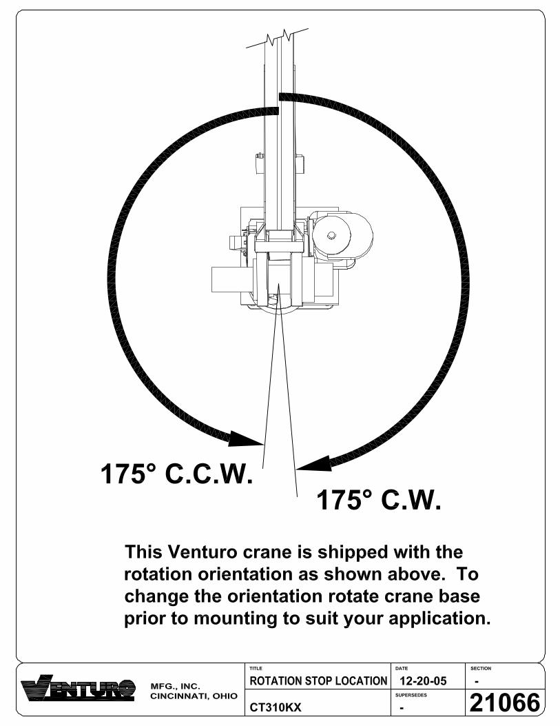
INSTALLATION INSTRUCTIONS......................................................................................................... 20562Installation Procedure ............................................................................................................................ 20563Installation Dimensions Drawing ........................................................................................................... 20564Base mounting Dimensions ........................................................................................................... 20714Rotation Stop Location ................................................................................................................. 21066Battery Cable Installation Drawing ....................................................................................................... 20565Final Preparation Prior To Use .............................................................................................................. 20566
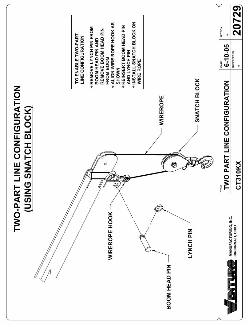
OPERATION INSTRUCTIONS ............................................................................................................... 20567Control Pendant and Overload Sensing System..................................................................................... 20568Truck Setup, Swivel Snatch Block Use, Preparation for Travel ............................................................ 20569Two part line configuration .................................................................................................................... 20729
MAINTENANCE AND SERVICE............................................................................................................ 20570Preventative Maintenance Overview, Periodic Inspection Schedule ..................................................... 20571Lubrication Schedule .............................................................................................................................. 20572Minimum Voltage Test ........................................................................................................................... 20573Wire Rope Installation and Replacement ............................................................................................... 20574Hydraulic System Schematic ................................................................................................................. 20575
REPLACEMENT PARTS (ILLUSTRATED PARTS CATALOG) ...................................................... 20576General Replacement Parts Drawing and List ...................................................................................... 20577Hydraulic System Parts Drawing .......................................................................................................... 20578Hydraulic System Parts List .................................................................................................................. 20883Electrical System Parts Drawing ........................................................................................................... 20876Electrical System Parts List ................................................................................................................... 20877Winch Replacement Parts Kit ................................................................................................................ 20837Pendant (4 Switch) Parts Drawing ........................................................................................................ 20875Pendant (4 Switch) Parts List ................................................................................................................ 20878Decal Parts Drawing ............................................................................................................................. 20881Decal Parts List ..................................................................................................................................... 20882
20880Rev. A - 4-26-07

Venturo CranesInstruction Manual
Page 3
Introduction
INTRODUCTION
20551

Page 4
Model CT310KXInstruction Manual
Figure 1 - 1 CT310KX Crane (Shown in Stowed Position)
Introduction20552

Page 5
NOTES
Model CT310KXInstruction Manual
Introduction
INTRODUCTION
This manual is prepared for the truck mounted crane Model CT310KX.
The CT310KX crane is a electric/hydraulic powered, pedestal mounted unit manu-factured by Venturo Manufacturing, Inc. of Cincinnati, Ohio.
The boom on this crane extends 32 inches hydraulically with an additional 32 inchmanual extension. In the retracted position, the boom is 4 1/2 feet long. When fullyextended, the boom is 9 1/2 feet long.
About This ManualThe sections included in this manual are listed below.Introduction
The introduction section provides an overview of the use of the crane.Safety
Safe operating and maintenance procedures are introduced in this section.Also included is an explanation of the safety warnings and signs used onthe crane.
InstallationThe installation section provides instructions for installing the crane onyour truck.
OperationOperating instructions are provided for the safe and efficient operation ofthe crane.
MaintenancePreventive maintenance inspections and the crane lubrication schedulesare listed in this section. Replacement and adjustment procedures areprovided.
Illustrated Parts CatalogReplacement part numbers and ordering procedures are provided in thissection.
LIMITS OF USEThe CT310KX crane is designed to lift loads up to the limits as shown in thecapacity chart (figure 1 - 2).• Lifting of personnel is NEVER permitted.• Lifting loads exceeding the capacity chart in figure 1 - 2 voids the war-
ranty agreement.
20553

VENCO VENTURO INDUSTRIES LLC
CINCINNATI, OHIO
C100MAXIMUM LOAD CAPACITY
CT310KX
05-03-16E
DATE SECTION
SUPERSEDES
TITLE
08-12-13C
20554
MAXIMUM LOAD CAPACITY CHART
CT310KX
CRANE SERIAL NUMBER: ________________
WEIGHT OF LOAD HANDLING DEVICES ARE PART OF THE LOAD AND MUST BE DEDUCTED FROM THE GROSS CAPACITY.
LOAD BLOCK USAGE
1 PART LINE FOR LOADS LESS THAN 1000 LBS
2 PART LINE FOR LOADS OF 1000 LBS AND GREATER
WEIGHT OF LOAD BLOCK = 5 LBS
2
HORIZONTAL REACH (FT)
VE
RT
IC
AL
H
EIG
HT
(F
T)
5
4
3
8 10976543
-1
-2
-3
-4
0
1
210
-5
6
7
8
9
11
12
13
14
10
700
1250
1900

Venturo CranesInstruction Manual
Page 7
SAFETY
Safety20555

Page 8
NOTES
Model CT310KXInstruction Manual
Safety
SAFETY - GENERALWith proper installation, cranes can be operated and maintained safely. By usingcommon safety practices along with an awareness of potential hazards the job canbe done safely.
Each time a crane is used, there may be a new and different environment. Eachtime there is a need to look at these situations for potential new hazards. Whereyou park your truck is important for the work to be done and done safely. Askingothers to stop or move their activity away from your truck may be best. And, ofcourse, there is the need to look for overhead power lines and other obstacles toavoid during the operation of the crane. Sometimes the load itself can present ahazard; loads may be damaged or broken, the load may contain hazardous mate-rials or the load may come close to exceeding the maximum capacity of the crane.
Safety awareness is a continuing job. Below is list of general points for safe craneoperation. Read these points and add your own points. There may be uniquesafety needs for the use of your crane and the product or service you provide.
Crane Safety
• Always turn off the truck ignition and turn off the master disconnect switchbefore performing any maintenance or repairs to the crane equipment.
• Never walk or stand under the boom or a suspended load.• Never operate the crane with a frayed cable.• Never allow the crane to be used to lift, support or otherwise transport
personnel.• Training by a knowledgeable crane operator is required before operating
the crane.• Read and understand this manual before operating the crane.• Always warn others to stand clear of your operating area.• Always inspect the crane each day before use for its safe operating
condition.• Always refer to the load capacity chart before using the crane.• Always attach the pendant cord support snap to the attachment point
before plugging in the pendant.• Always unplug the pendant when then crane is not in use.• Always turn off the master disconnect switch when the crane is not in use.• Always place the crane in the stowed position before traveling.
20556

Page 9
NOTES
Model CT310KXInstruction Manual
Safety
ELECTROCUTION HAZARD
Cranes are capable of contacting overhead obstructions. Power lines create aspecial hazard. In addition to direct contact, just getting close to these lines is ahazard. And the higher the voltage carried by those lines, the higher the danger.This hazard has its own set of special safety rules.
Crane Safety Near Power Lines• Always remember, the truck and crane are not insulated!• Always maintain a safe distance from power lines. Always keep the
boom, its load and loadline at least ten (10) feet away from any powerline.Additionally;
Allow room for swaying, sag and rocking.Increase the distance to fifteen (15) feet or more from lines carryinghigher power. (Even when you are not sure.)
• Failure to follow these rules can result in death or serious injury!
Table 2 - 1 Required Minimum Clearances
20557
secnaraelCmuminiMderiuqeR
)Vk(egatloVlanimoN)esahPoTesahP(
morF*)teeF(ecnaraelCderiuqeRmuminiMseniLegatloV-hgiHdaehrevO
05-0002-05revO053-002revO005-053revO057-005revO0001-057revO
015102525304
)Vk(egatloVlanimoN)esahPoTesahP(
morF*)teeF(ecnaraelCderiuqeRmuminiMnIelihW(srotcudnoCegatloV-hgiHdezigrenE
)tisnarT
57.0-005-57.0revO543-05revO057-543revO0001-057revO
46016102
latnemnorivnE:ETON*,gofsahcussnoitidnoc
noitatipicerproekomsdesaercnieriuqeryam
.secnaraelc

Page 10
NOTES
Model CT310KXInstruction Manual
Safety
• Always used to warn of haz-ards that could result in deathor serious injury.
• Always used to warn of haz-ards that could result in injury.
• Always used to warn of haz-ards that could result in equip-ment damage or minor injury.
20558
Safety WarningsSafety warnings have been included in this manual to alert you to the need for carein specific procedures. These warnings include the use of three (3) terms; DAN-GER, WARNING and CAUTION. Their uses are defined as follows.
Any DANGER warning indicates that failure to follow this safe practice couldresult in death or serious injury.
Any WARNING indicates that failure to follow this safe practice could result ininjury.
Any CAUTION indicated that failure to follow this instruction could result in aminor injury or damage to the equipment.

Page 11
NOTES
Model CT310KXInstruction Manual
Electrocution Hazard SignsTwo decals are provided with the crane
This sign is to be placed on all four (4) sides of the truck. Each is to be placed ina readily visible location for all to see. This sign is provided with the crane. Addi-tional signs are available from Venturo Manufacturing, Inc. The sign part numberis 15393A.
This sign is a reminder of the legal responsibility of any person operating the cranenear high voltage lines. The sign is placed on the control pendant side of the boom.This sign is provided with the crane. Additional signs are available from VenturoManufacturing, Inc. The sign part number is 15401.
Decals and signs have been placed on the crane as reminders of the care andprecautions needed for safety. These items are to be inspected periodically forreadability and need for replacement. The preventive maintenance informationincludes an inspection of these decals and signs. Any unreadable or missing decalor sign must be replaced. See the Illustrated Parts List for ordering information.
Safety20559

Model CT310KXInstruction Manual
Page 12
See The Next PageFor
Additional Information!
Safety Signs And DecalsAll cranes are equipped with warning and informational signs and decals. Eachsign and decal is positioned to provide reminders for safe, efficient operating andmaintenance procedures for the crane. Below is a description of the winch safetywarnings.
Unreadable or missing signs and decals must be replaced. The next page de-scribes the location and part number for each. Refer to the Illustrated Parts Cata-log section for parts ordering information.
Winch SafetyThe use of the crane involves careful use of its winch. Below are three dangerreminders of very important rules.
Safety20560


VENCO VENTURO INDUSTRIES LLC
CINCINNATI, OHIO
C150SAFETY DECALS
VENTURO CRANES
04-29-16E
DATE SECTION
SUPERSEDES
TITLE
10-24-13D
21353
DECAL #: 15390
DESCRIPTION: CAUTION, INSPECT VEHICLE & CRANE...
PURPOSE: TO INFORM THE OPERATOR OF KEY OPERATING REQUIREMENTS.
QUANTITY: 1
PLACEMENT: REAR COVER OR SIDE OF CRANE
DECAL #: 15391
DESCRIPTION: DANGER, NOT A PASSENGER LIFT
PURPOSE: TO INFORM OPERATOR NOT TO LIFT, SUPPORT, OR TRANSPORT
PERSONNEL, AND TO ENSURE OPERATOR IS ADEQUATELY TRAINED.
QUANTITY: 1
PLACEMENT: REAR COVER OR SIDE OF CRANE
15390-D
!CAUTION
1. INSPECT VEHICLE AND CRANE INCLUDING
OPERATION, PRIOR TO USE DAILY.
2. DO NOT USE THIS EQUIPMENT EXCEPT ON
SOLID, LEVEL SURFACE WITH CRANE
MOUNTED ON FACTORY-RECOMMENDED
TRUCK.
3. BEFORE OPERATING THE CRANE, REFER TO
MAXIMUM LOAD (CAPACITY) CHART ON CRANE
FOR OPERATING (LOAD) LIMITATIONS.
4. DO NOT OPERATE, WALK, OR STAND BENEATH
BOOM OR A SUSPENDED LOAD.
5. UNPLUG PENDANT AND SHUT OFF MASTER
DISCONNECT SWITCH WHEN CRANE NOT IN
USE.
6. FOR TRAVEL, BOOM MUST BE IN STOWED
POSITION.
DANGER!THIS CRANE IS NOT A PASSENGER LIFT
IT IS NOT DESIGNED OR INTENDED TO BE USED TO LIFT,
SUPPORT OR OTHERWISE TRANSPORT PERSONNEL.
YOU MUST NOT
OPERATE THIS CRANE UNLESS:
1. YOU HAVE BEEN TRAINED IN THE SAFE
OPERATION OF THIS CRANE; AND
2. YOU KNOW AND FOLLOW THE SAFETY AND
OPERATING RECOMMENDATIONS CONTAINED IN
THE MANUFACTURER'S MANUALS, YOUR
EMPLOYER'S WORK RULES, AND APPLICABLE
GOVERNMENT REGULATIONS.
AN UNTRAINED OPERATOR SUBJECTS HIMSELF
AND OTHERS TO DEATH OR SERIOUS INJURY .
15391-D
THIS MACHINE IS NOT INSULATED
ELECTROCUTION HAZARD
MAINTAIN SAFE CLEARANCES FROM ELECTRICAL
LINES AND APPARATUS. YOU MUST ALLOW FOR
BOOM SWAY, ROCK OR SAG, AND ELECTRICAL
LINE AND LOAD LINE SWAYING.
THIS LIFTING DEVICE DOES NOT PROVIDE PRO-
TECTION FROM CONTACT WITH OR PROXIMITY
TO AN ELECTRICALLY CHARGED CONDUCTOR.
YOU MUST MAINTAIN A CLEARANCE OR AT LEAST
10 FEET BETWEEN ANY PART OF THE CRANE, LOAD
LINE OR LOAD, AND ANY ELECTRICAL LINE OR
APPARATUS CARRYING UP TO 50,000 VOLTS. ONE
FOOT ADDITIONAL CLEARANCE IS REQUIRED FOR
EVERY ADDITIONAL 30,000 VOLTS OR LESS.
DEATH OR SERIOUS INJURY WILL RESULT FROM
CONTACT OR INADEQUATE CLEARANCE.
15392-E
DANGER!
D A N G E R!
UNLAWFUL TO OPERATE THIS EQUIPMENT
WITHIN 20 FEET OF HIGH-VOLTAGE LINES
OF 350,000 VOLTS OR LESS.
FOR MINIMUM CLEARANCES OF HIGH-VOLTAGE LINES IN EXCESS OF 350,000 VOLTS, REFERENCE OSHA 1926.1408,
CRANE'S SAFETY MANUAL, AND CAL-OSHA ARTICLE 37, TITLE 8, HIGH-VOLTAGE ELECTRICAL SAFETY ORDERS.
15401-D
ELECTROCUTION HAZARD
KEEP CLEAR OF TRUCK AND LOAD
DEATH OR SERIOUS INJURY CAN RESULT FROM
CONTACT WITH THE LOAD, THE CRANE, OR THE
VEHICLE IF BOOM OR LOAD LINE SHOULD BECOME
ELECTRICALLY CHARGED.
15393-C
!DANGER
DECAL #: 15392
DESCRIPTION: DANGER, ELECTROCUTION HAZARD, MACHINE (CRANE)
PURPOSE: TO INFORM OPERATOR THAT MACHINE (CRANE) REPRESENTS AN
ELECTROCUTION HAZARD SHOULD IT COME CLOSE TO OR IN CONTACT
WITH AN ELECTRICAL VOLTAGE SOURCE.
QUANTITY: 1
PLACEMENT: REAR COVER OR SIDE OF CRANE
DECAL #: 15401
DESCRIPTION: DANGER, UNLAWFUL TO OPERATE
PURPOSE: TO INFORM OPERATOR OF PROPER OPERATION
IN VICINITY OF ELECTRICAL LINES.
QUANTITY: 1
PLACEMENT: RING COVER OR SIDE OF CRANE
DECAL #: 15393
DESCRIPTION: DANGER, ELECTROCUTION HAZARD, VEHICLE (TRUCK)
PURPOSE: WARNS OF DANGER FROM ELECTRICALLY CHARGED
VEHICLE, CRANE, OR LOAD.
QUANTITY: 4
PLACEMENT: EACH SIDE & EACH END OF VEHICLE


Venturo CranesInstruction Manual
Page 14
Installation Instructions
INSTALLATIONINSTRUCTIONS
20562

TITLE DATE SECTION
SUPERSEDES 20563C100
CT310KX 12-06-12B
03-04-13CINST INSTRUCTIONS
CT310KX INSTALLATION INSTRUCTIONS
MANUFACTURING, INC.
CINCINNATI, OHIO
INSTALLATION PROCEDUREYour new crane is shipped in a ready-to-install condition. Follow the instructions in this
section to properly install the crane onto your truck.
INSPECT FOR SHIPPING DAMAGEInspect the crane immediately after receipt, even if installation will not occur
immediately.
· Remove packaging materials as needed
· Inspect for crushed, bent, or otherwise damaged conditions.
· Report any damage found to the carrier.
CRANE MOUNTINGRefer to drawings 20577 & 20564
The crane base is connected to the mounting pedestal using four [4] M20-1.5MM X
70MM, Class 10.9 Hex Head Cap Screw Bolts, [8] Flat Washers, and [4] Nylon-insert
Hex Lock Nuts (supplied).
Torque Hex Nuts to standard torque value of 401 ft*lbs.
The mounting pedestal is connected to the truck frame using equivalent hardware (not
supplied).
For installations less mounting pedestal, use the provided metric mounting hardware
(as referenced above) to secure the crane base directly to the truck frame.
NOTE: The mounting pedestal provides the necessary mast height to 'fully' lower the
boom to minimize storage area required.
INSTALL BATTERY CABLES1. Refer to for battery cable installation.
2. Install #2 gauge wiring.
2.a. Be sure to install a circuit breaker into the wiring from the battery
(VENTURO P/N 19417-150 recommended).
3. Install grounding strap(s).
3.a. Install #2 gauge grounding strap from crane base to truck frame.
3.b. If truck battery negative terminal is connected to engine, install a #2
gauge grounding strap from the engine to truck frame.
WIRE ROPE INSTALLATIONRefer to figure 5-2 (Maintenance Section) for information on wire rope installation /
replacement.
NOTES

Page 1
Model CT310KXInstruction Manual
Installation Instructions20564
Figu
re 3
- 1
Inst
alla
tion/
Dim
ensi
on D
raw
ing
SW
ING
RA
DIU
SH
YD
RA
UL
IC(P
OW
ER
)M
AN
UA
L
ST
OW
ED
PO
SIT
ION
BA
SE
MO
UN
TIN
GD
IME
NS
ION
S
64"
R13
1/8
"9"
9"
109"
139"
169"
53"
85"
117"
32"
32"
40"
64"
8"
C.G
. (A
PP
RO
X)
3-31-04A

SECTIONDATE
SUPERSEDES
TITLE
CT310KX
C20003-12-13B
03-08-05
BASE MOUNTING DIM
20714
R
MANUFACTURING, INC.
CINCINNATI, OHIO
9"
3/4"
10 1/2"
10 1/2"
3/4"
9"
Ø5"
5 1/4"
5 1/4"
Ø13/16" 4 PLACES
CT310KX MOUNTING DIMENSION
R3/4" 4 PLACES
REFERENCE INSTALLATION DWG 20563 FORMOUNTING BOLT SIZE AND TORQUE SPECIFICATIONS.

Page 17
Model CT310KXInstruction Manual
Impo
rtan
t: T
he c
rane
mus
t mak
e co
nnec
tion
with
the
nega
tive
of th
e ba
ttery
. T
o in
sure
this
,1.
Inst
all a
#2
gaug
e gr
ound
ing
stra
p fr
om th
e en
gine
to th
e tr
uck
fram
e (r
equi
red
if ne
gativ
e fr
om b
atte
ry is
conn
ecte
d to
the
engi
ne).
2. In
stal
l a #
2 ga
uge
grou
ndin
g st
rap
from
the
cran
e ba
se to
the
truc
k fr
ame,
incl
uded
with
ET
6R,
ET
10K
(X),
ET
25K
, ET
25K
X &
CT
310K
X c
rane
s.
No
te: F
ailu
re to
do
thes
e st
eps
may
resu
lt in
inte
rmitt
ent o
pera
tion
of e
lect
ric c
rane
.
Mas
ter d
isco
nnec
tsw
itch
nece
ssar
yfo
r saf
ety
(loca
te
Eng
ine
totr
uck
fram
e
Atta
ch c
able
to b
atte
ry te
rmin
alor
sta
rter
sol
enoi
d ("
hot"
sid
e)
Fus
e or
circ
uit b
reak
er (P
/N 1
9417
) rec
omm
ende
d.Lo
cate
as
clos
e to
sta
rter
or
batte
ry a
s is
pra
ctic
al.
ET6
KR
show
nB
atte
ry *
Pow
er u
nit c
able
*
20565 Venturo Electric CranesInstruction Manual
Installation Instructions
Fig
ure
3 - 2
Bat
tery
Cab
le In
stal
lati
on D
raw
ing

Page 18
NOTES
Model CT310KXInstruction Manual
Installation Instructions
FINAL PREPARATION FOR USE
1. Check all bolts and nuts for tightness.
2. Check all electrical connections for tightness.
3. Inspect the entire crane to be sure that it is ready for use.
4. Verify that the hydraulic reservoir is filled with hydraulic fluid (with bothcylinders fully retracted).
5. Check the crane operation.
A. Put the truck’s transmission in Neutral (Park if it has an automatictransmission).
B. Remove the pendant from its stowed location and plug it into itssocket.
C. Check each of the four operations by operating each switch in bothdirections:• Winch Down/Up• Boom Up/Down• Boom Out/In• Rotation Left/Right
NOTE: The crane is now ready for operation.
6. After 10 Hours of operation, repeat steps 1 through 4.
20566

Venturo CranesInstruction Manual
Page 19
Operation Instructions
OPERATIONINSTRUCTIONS
20567
Page 20
Model CT310KXInstruction Manual
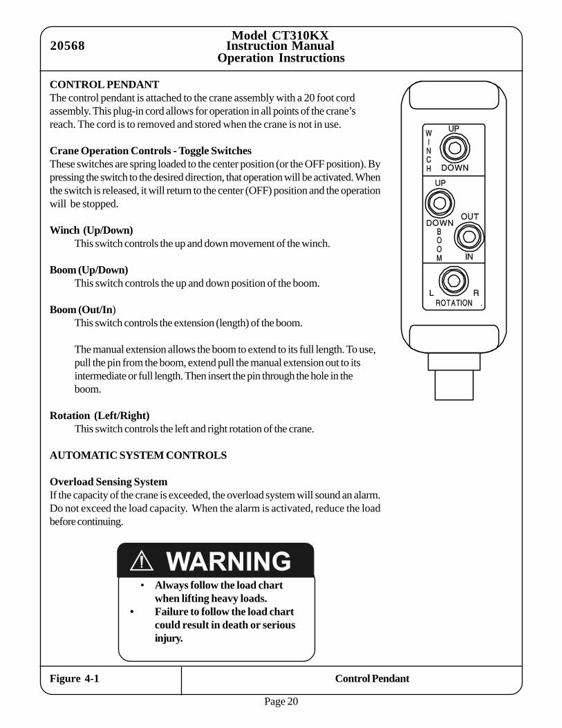
Figure 4-1 Control Pendant
CONTROL PENDANTThe control pendant is attached to the crane assembly with a 20 foot cordassembly. This plug-in cord allows for operation in all points of the crane’sreach. The cord is to removed and stored when the crane is not in use.
Crane Operation Controls - Toggle SwitchesThese switches are spring loaded to the center position (or the OFF position). Bypressing the switch to the desired direction, that operation will be activated. Whenthe switch is released, it will return to the center (OFF) position and the operationwill be stopped.
Winch (Up/Down)This switch controls the up and down movement of the winch.
Boom (Up/Down)This switch controls the up and down position of the boom.
Boom (Out/In)This switch controls the extension (length) of the boom.
The manual extension allows the boom to extend to its full length. To use,pull the pin from the boom, extend pull the manual extension out to itsintermediate or full length. Then insert the pin through the hole in theboom.
Rotation (Left/Right)This switch controls the left and right rotation of the crane.
AUTOMATIC SYSTEM CONTROLS
Overload Sensing SystemIf the capacity of the crane is exceeded, the overload system will sound an alarm.Do not exceed the load capacity. When the alarm is activated, reduce the loadbefore continuing.
Operation Instructions20568
• Always follow the load chartwhen lifting heavy loads.
• Failure to follow the load chartcould result in death or seriousinjury.

Page 21
NOTES
Model CT310KXInstruction Manual
Operation Instructions
TRUCK SET UP FOR OPERATION
1. The truck should be parked on firm, level ground when using the crane.
2. The crane should be positioned close to the job so that it can operatewithin its capacity limits.
3. Set the truck parking brake.
4. Put the truck’s transmission in Neutral (Park if it has an automatic trans-mission).
5. Remove the pendant from its stowed location and plug it into its socket.
6. Turn on the master disconnect switch.
7. Set the outriggers (when provided) to help stabilize the truck to preventrocking or overturning of the truck when using the crane.
USING THE SWIVEL SNATCH BLOCKThe swivel snatch block must be used for loads over 1200 pounds. It may beused for all loads to prevent twisting and turning of the load.
PREPARATION FOR TRAVEL
1. Return the outriggers (if used) to the stowed position. Install and secure allpins
2. Run the BOOM IN to fully retract the boom.
3. Manually retract the boom’s manual extension (if used). Pull the pin fromthe boom and push the extension into the fully retracted position. Insertthe pin in the hole in the boom.
4. Run the BOOM DOWN to lower to boom to the stowed position. Seefigures 1 - 1 or 2 - 1.
5. Unplug the pendant control cord and stow in a body compartment or thecab.
6. Turn off the master disconnect switch.
20569

Venturo CranesInstruction Manual
Page 22
Maintenance
MAINTENANCE
20570
Page 23
NOTES
Model CT310KXInstruction Manual
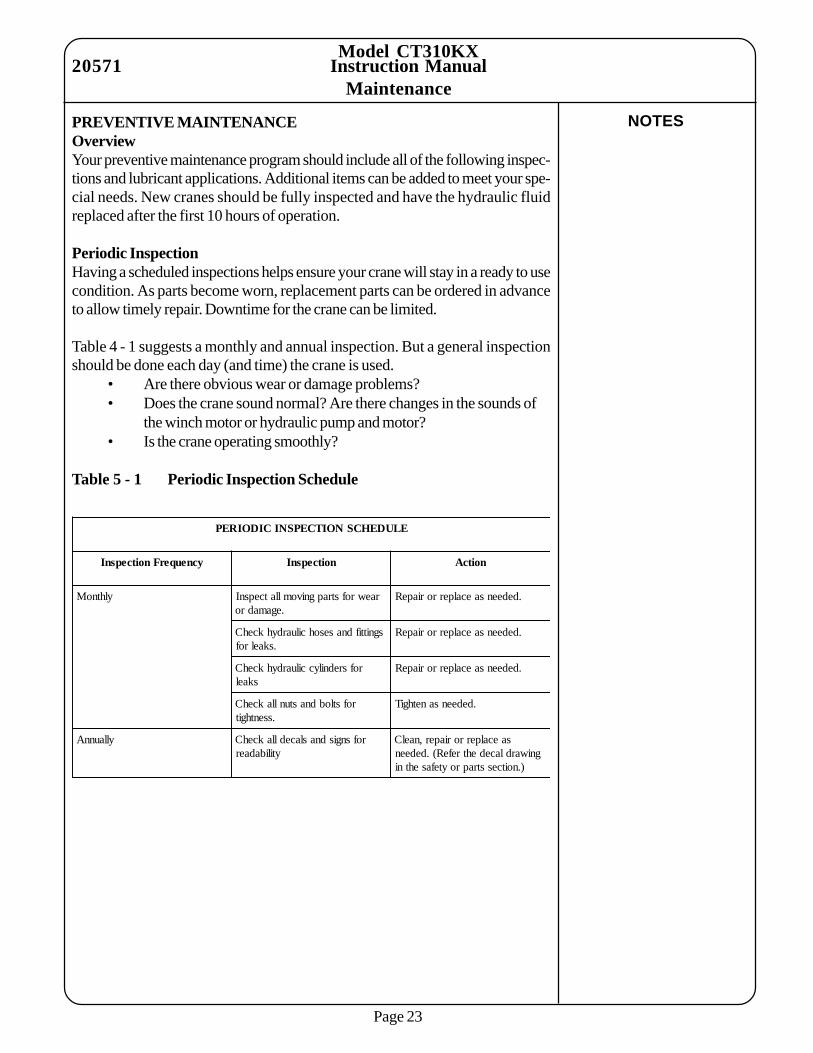
PREVENTIVE MAINTENANCEOverviewYour preventive maintenance program should include all of the following inspec-tions and lubricant applications. Additional items can be added to meet your spe-cial needs. New cranes should be fully inspected and have the hydraulic fluidreplaced after the first 10 hours of operation.
Periodic InspectionHaving a scheduled inspections helps ensure your crane will stay in a ready to usecondition. As parts become worn, replacement parts can be ordered in advanceto allow timely repair. Downtime for the crane can be limited.
Table 4 - 1 suggests a monthly and annual inspection. But a general inspectionshould be done each day (and time) the crane is used.
• Are there obvious wear or damage problems?• Does the crane sound normal? Are there changes in the sounds of
the winch motor or hydraulic pump and motor?• Is the crane operating smoothly?
Table 5 - 1 Periodic Inspection Schedule
ELUDEHCSNOITCEPSNICIDOIREP
ycneuqerFnoitcepsnI noitcepsnI noitcA
ylhtnoM raewrofstrapgnivomllatcepsnI.egamadro
.dedeensaecalperroriapeR
sgnittifdnasesohciluardyhkcehC.skaelrof
.dedeensaecalperroriapeR
rofsrednilycciluardyhkcehCskael
.dedeensaecalperroriapeR
rofstlobdnastunllakcehC.ssenthgit
.dedeensanethgiT
yllaunnA rofsngisdnaslacedllakcehCytilibadaer
saecalperroriaper,naelCgniwardlacedehtrefeR(.dedeen
).noitcesstraproytefasehtni
Maintenance20571

Page 24
NOTES
Model CT310KXInstruction Manual
LubricationThe grease should be selected based upon your operating temperatures and envi-ronment. Select lighter weight greases for colder temperature operation and heaviergreases when operating in warmer temperatures.
The hydraulic fluid should be ISO Grade 46
Table 5 - 2 Lubrication Schedule
ELUDEHCSNOITACIRBUL
ycneuqerFnoitaciruL tnioPnoitacirbuL tnacirbuL
ylkeeW noisnetxemooB esaerG3RO2PEIGLN
esabtasgnittifesaerG esaerG3RO2PEIGLN
ylhtnoM diulfciluardyhfolevelkcehC diulfciluardyh64edarGOSIddA.dedeensa
yllaunnA diulfciluardyhecalpeR OSIhserfhtiwllif;knatehtniarD.diulfciluardyh64edarG
-
Maintenance20572

Page 25
Model CT310KXInstruction Manual
Maintenance20573
Figure 5 - 1 Minimum Voltage Test
MINIMUM VOLTAGE TESTThis test checks the system voltage when under a full load condition. If a minimumof 9 volts is not read, the battery must be changed.To check:1. Start the truck engine.
2. Operate the Boom UP switch until the boom is at the full UP position.3. Pull back the rubber boot which covers the motor terminal.4. While holding the Boom Up switch on, measure the voltage at the HOT
connection (at the hydraulic pump motor) across to ground (on the cranehousing).
5. Operate the Boom DOWN switch to lower the boom.6. Replace the battery if the reading is less than 9 volts.
• Never touch moving parts• Allow only trained personnel to
perform this test.• Failure to follow this could
result in serious injury.

Page 26
Model CT310KXInstruction Manual
WINCH LINE REPLACEMENT1. Remove the wedge from the old winch line for use with the new line.2. Remove the old winch line and clean the winch if needed.3. Unroll the new winch line to prevent kinking.4. Thread the new winch line through the boom to the winch.5. Insert the new line through the slot in the drum.6. Form a loop and insert the end of the line into the slot.
• Be sure the “live” or load carrying end of the line is against the drumflange.
• Be sure the end of the rope extends out of the slot.7. Insert the wedge into the loop.
• Seat the wedge into the slot.8. Turn the truck engine ON.9. Wind the line onto the drum by pressing the winch UP switch.
• Maintain tension on the line at all times.• Wind the line evenly onto the drum.
Figure 5 - 2 Winch Line Replacement/Installation
Maintenance20574

Page 27
Model CT310KXInstruction Manual
Maintenance20575
Figure 5 - 3 Hydraulic System Schematic

Venturo CranesInstruction Manual
Page 28
ILLUSTRATEDPARTS
CATALOG
Illustrated Parts Catalog20576
CALL VENTURO MANUFACTURINGAT 800-226-2238 FOR...
• TECHNICAL SUPPORT• REPLACEMENT PARTS• DISTRIBUTOR RECOMMENDATION

SECTIONDATE
SUPERSEDES
TITLE
CT310KX
-03-04-13F
12-18-12E
REPLACEMENT PARTS
20577
R
MANUFACTURING, INC.
CINCINNATI, OHIO
2
1
15
14
12
13
10
9
11
16
7
4
5
6
8
7
NOTE: SEE HYDRAULIC AND ELECTRIC DRAWING FOR ADDITIONAL PARTS
18
17

RL
BO
BI
BU
RR
RL
PR
ES
SU
RE
HY
DR
AU
LIC
RO
TA
TIO
NM
OT
OR
BD
BD
BU
EL
EV
AT
ION
CY
LIN
DE
R
1
2 3
4
5
6
RR
RL
RE
PR
9
HY
DR
AU
LIC
PO
WE
RU
NIT
BO
BI
EX
TE
NS
ION
CY
LIN
DE
R
BI
BO
BU
BD
RR
15
17
15
14
7
16
16
11
17
13
8
BR
EA
TH
ER
CA
P2
09
73
10
12
18
RE
TU
RN
-H
YD
RA
ULIC
SY
ST
EM
PA
RT
SD
WG
CT
310
KX
03-1
5-1
3D
DA
TE
SE
CT
ION
SU
PE
RS
ED
ES
TIT
LE
20
578
06-1
7-1
1C
R
MA
NU
FA
CT
UR
ING
,IN
C.
CIN
CIN
NA
TI,
OH
IO

Model CT310KXInstruction Manual
Page 1
Illustrated Parts Catalog
ItemNumber
QuantityPer Assembly
PartNumber
PartDescription
208834/26/07
! - SWITCH, Overload Pressure ............................................................ 12 H6506-0406 FITTING, 4FP-6FJX ........................................................................ 13 H9159-060606 FITTING, Metric Tee ........................................................................ 14 H6505-0406 FITTING, 4MP-6FJX ....................................................................... 15 H2503-0604 FITTING, 8MJ-4MP x 45 ................................................................. 16 17455 VALVE, Flow Control ....................................................................... 17 H6400-0604 FITTING, 6MJ-4MO........................................................................ 78 H6801-0604 FITTING, 6MJ-4MO x 90 ................................................................ 19 H2501-0606 FITTING, 6MJ-6MP x 90 ................................................................. 110 H2501-0604 FITTING, 6MJ-4MP x 90 ................................................................. 111 19815-2 VALVE BLOCK, Assembly .............................................................. 112 20406 POWER UNIT, Hydraulic ................................................................. 113 20457-3 HOSE, Pressure (supply) ................................................................... 114 20457-2 HOSE, Return ................................................................................... 115 20457-4 HOSE, Elevation (Boom Up & Down) .............................................. 216 20457-6 HOSE, Extension (Boom Out & In) ................................................... 217 20457-1 HOSE, Rotation (Left & Right) .......................................................... 2* 20457 KIT, Fitting And Hoses (*Not Shown*) ............................................. 1
Parts List For Illustrated Parts Catalog Figure 6 - 2


Model CT310KXInstruction Manual
Page 1
Illustrated Parts Catalog
ItemNumber
QuantityPer Assembly
PartNumber
PartDescription
20877
! 19608 RELAY ............................................................................................. 12 21391 SOCKET & CAP Assembly .............................................................. 13 - VALVE BLOCK Assembly (See Hydraulic System Parts ) ................ 14 - HARNESS, Ground .......................................................................... 25 - See Hydraulic System Parts6 20499 CONTACTOR ................................................................................. 17 17356 ALARM, Overload ........................................................................... 18 17460-2200 SWITCH, Overload Pressure ............................................................ 19 - HARNESS ....................................................................................... 1
Optional Equipment10 19417-150 CIRCUIT BREAKER (Not Shown) .................................................. 1
Parts List For Illustrated Parts Catalog Figure 6 - 3
4-9-07

-R
EP
LA
CE
ME
NT
PA
RT
SD
RA
WIN
G
CT
31
0K
X&
ET
6K
01-2
6-1
5D
DA
TE
SE
CT
ION
SU
PE
RS
ED
ES
TIT
LE
20837
12-2
7-1
3C
20
78
8M
OT
OR
RE
PLA
CE
ME
NT
KIT
INC
LU
DE
SE
ND
PIE
CE
20
49
9C
ON
TA
CT
OR
21
21
4C
AB
LE
WE
DG
E
20
58
6W
INC
HR
EP
LA
CE
ME
NT
PA
RT
S
®V
EN
CO
VE
NT
UR
OIN
DU
ST
RIE
SLLC
CIN
CIN
NA
TI,
OH
IO

Model CT310KXInstruction Manual
Page 1
Illustrated Parts Catalog
ItemNumber
QuantityPer Assembly
PartNumber
PartDescription
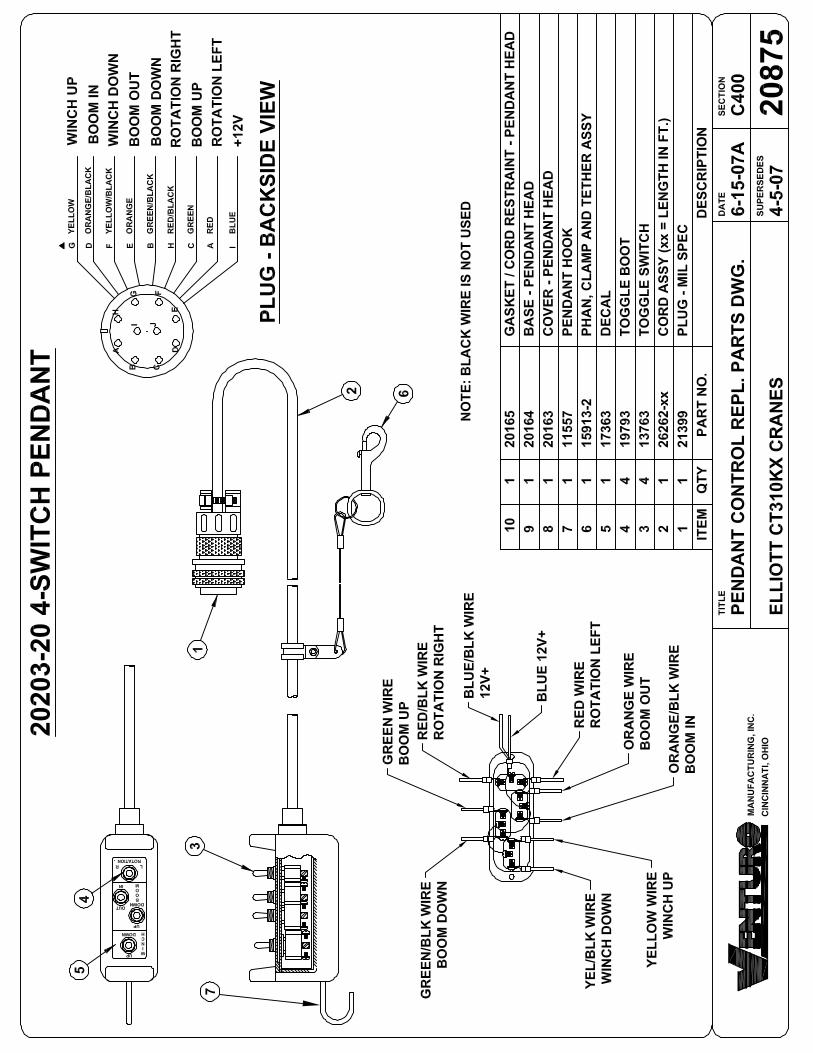
1 21399 MILSPEC PLUG .............................................................................. 12 26262-20 CORD Assembly ( 20 ft Long) .......................................................... 13 13763 SWITCH, Toggle .............................................................................. 44 19793 BOOT, Toggle ................................................................................... 45 17363 DECAL ............................................................................................ 16 15913-2 PHAN, CLAMP AND TETHER Assembly ...................................... 17 11557 HOOK, Pendant ............................................................................... 18 20163 COVER, Pendant Head .................................................................... 19 20164 BASE, Pendant Head ........................................................................ 110 20165 GASKET/CORD RESTRAINT, Pendant Head ................................. 1
Parts List For Illustrated Parts Catalog Figure 6 - 4
208784/19/07


Model CT310KXInstruction Manual
Page 1
Illustrated Parts Catalog
ItemNumber
QuantityPer Assembly
PartNumber
PartDescription
1 20470 DECAL, Boom Angle ....................................................................... 22 15398 DECAL, Unplug Pendant .................................................................. 13 20474 DECAL, Capacity ............................................................................. 14 573402 DECAL, Danger, Two-Blocking ........................................................ 15 15392 DECAL ............................................................................................ 16 573403 DECAL, Warning, Stowing ................................................................ 17 15390 DECAL, Caution Instructions ............................................................ 18 15391 DECAL ............................................................................................ 19 14459 DECAL ............................................................................................ 110 20504 DECAL, CT310KX Model ............................................................... 111 16719 DECAL, Unlawful To Operate ........................................................... 112 13397 DECAL, Oil Level ............................................................................. 113 -
DECALS TO BE PLACED ON TRUCK14 15393A DECAL, Danger, Electrocution Hazard (See Safety Section) .............. 415 15401 DECAL, Unlawful To Operate... (See Safety Section) ........................ 1
DECAL KIT (FIELD SERVICE LABEL KIT) FOR CT310KX16 20503 KIT, Decals (Not Shown) .................................................................. 1
Parts List For Illustrated Parts Catalog Figure 6 - 5
208824-20-07


