ct-generations - · pdf filect-generations rad309 dr. eng. sarah dr. eng. sarah hagi. hagi....
TRANSCRIPT
CTCT--GenerationsGenerations RAD309RAD309
Dr. Eng. Sarah Dr. Eng. Sarah HagiHagi

Definition of Generation
Classification of computed tomography (CT) based upon: arrangement of components and mechanical motion required to collect data“Generation” the order in which CT scanner design has been introduced, and each has a number associated with itNOTE: higher generation number NOT a higher performance system

First GenerationDesign: single X-ray source and single X-ray detector cell to collect all the data for a single slice
Source and detector, rigidly coupled Beam: Pencil beam
translated across patient to obtain set of parallel projection measurements at one angle
Source/detector rotate slightly and a subsequent set of measurements are obtained during a translation past patientProcess is repeated once for each projection angle until 180 projections , across a 24 cm FOVTranslation and rotation process, this geometry is referred to as a translate/rotate scanner

First Generation CT
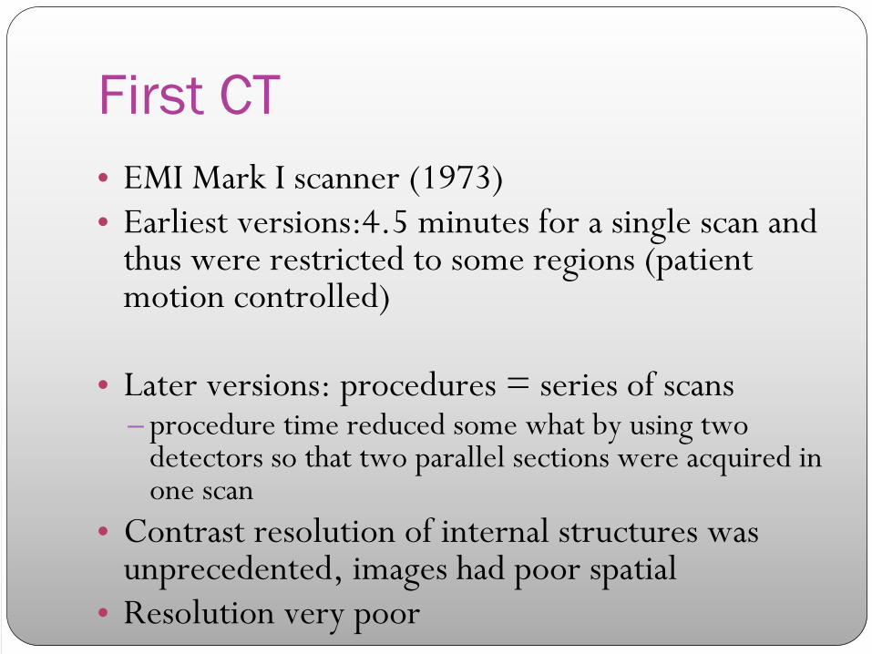
First CT• EMI Mark I scanner (1973)• Earliest versions:4.5 minutes for a single scan and
thus were restricted to some regions (patient motion controlled)
• Later versions: procedures = series of scans – procedure time reduced some what by using two
detectors so that two parallel sections were acquired in one scan
• Contrast resolution of internal structures was unprecedented, images had poor spatial
• Resolution very poor

1st CT Generation Image

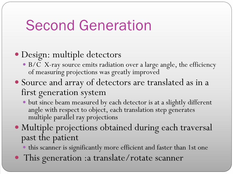
Second Generation
Design: multiple detectorsB/C X-ray source emits radiation over a large angle, the efficiency of measuring projections was greatly improved
Source and array of detectors are translated as in a first generation system
but since beam measured by each detector is at a slightly different angle with respect to object, each translation step generates multiple parallel ray projections
Multiple projections obtained during each traversal past the patient
this scanner is significantly more efficient and faster than 1st one
This generation :a translate/rotate scanner

Second Generation CT

Second CT• Pros: reducing scan time • The trunk could be imaged• By adding detectors angularly displaced , several
projections could be
obtained in a single translation • Early versions: 3 detectors each displaced
by1°
– Since each detector viewed the x-ray tube at a different angle , a single translation produced
3
projections
– The system could rotate 3°
to the next projection rather than 1°– make only 60 translations instead of 180 to acquire a complete section – Scan times were
reduced X 3
• Later versions: up to 53 detectors– Fast
enough (tens of seconds)to
permit acquisition during a single breath hold
– First designs to permit scans of the trunk– Because rotating anode tubes could not
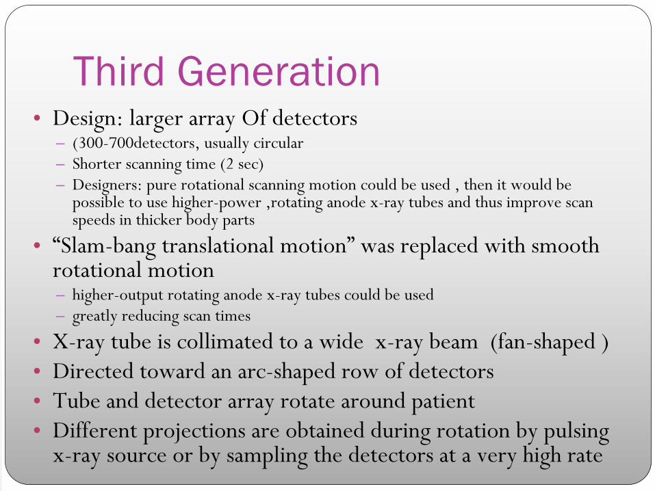
Third Generation• Design: larger array Of detectors
– (300-700detectors, usually circular– Shorter scanning time (2 sec)– Designers: pure rotational scanning motion could be used , then it would be
possible to use higher-power ,rotating anode x-ray tubes and thus improve scan speeds in thicker body parts
• “Slam-bang translational motion”
was replaced with smooth rotational motion– higher-output rotating anode x-ray tubes could be used– greatly reducing scan times
• X-ray tube is collimated to a wide x-ray beam (fan-shaped )• Directed toward an arc-shaped row of detectors• Tube and detector array rotate around patient • Different projections are obtained during rotation by pulsing
x-ray source or by sampling the detectors at a very high rate
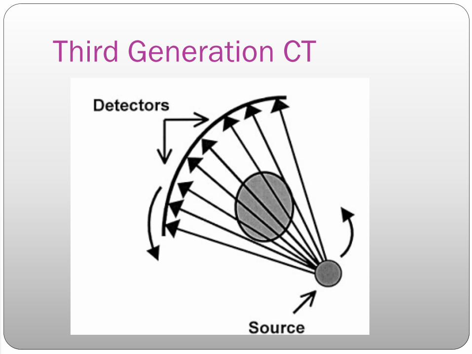
Third Generation CT

Third CTImprovement in detector and data acquisition technology
detector array with enough, high spatial resolution cells to allow measurement of a fan-beam projection of entire patient cross-section
Sampling considerations required scanning an additional arc of one fan angle beyond 180°, although most scanners rotate 360° for each scan. Current helical scanners are based on modifications of rotate-rotate designsScan times = few seconds or less, and recent versions are capable of subsecond scan timesImaging process is significantly faster than 1st or 2nd generation systems

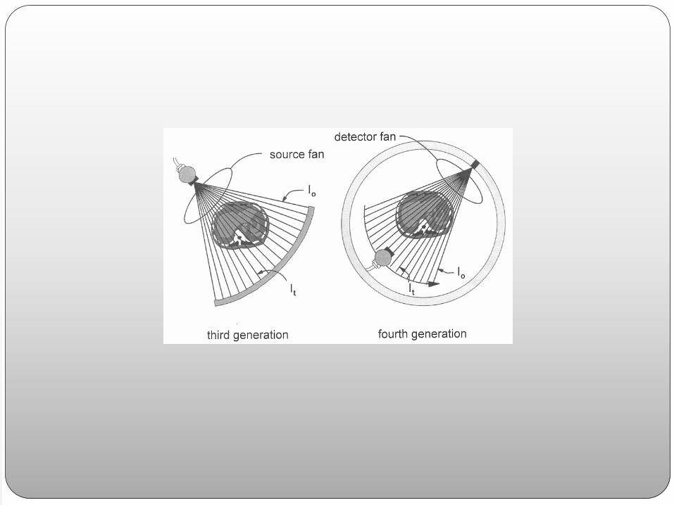
Rotate/rotate, wide fan beam
Number of detectors increased substantially (to more than 800 detectors)Angle of fan beam increased to cover entire patient
Eliminated need for translational motionMechanically joined x-ray tube and detector array rotate togetherNewer systems have scan times of ½ secondCons: very high performance detectors are needed to avoid ring artefacts and the system is more sensitive to aliasing than 1st or 2nd generation scanners
Fourth GenerationDesign: stationary detector ring & rotating X-ray tube
Reduced motion resulted in reduction in complexity
Stationary detector requires a larger acceptance angle for radiation, and is therefore more sensitive to scattered radiation than the 3rd generation geometry
Require larger number of detector cells and electronic channels (higher cost) to achieve the same spatial resolution and dose efficiency as a 3rd generation system
a rotate-stationary or rotate only geometry
Fourth CT

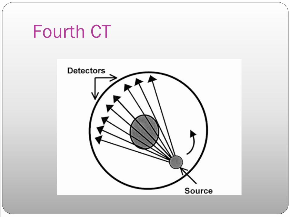
Fourth Generation CTDesign: also eliminated translate-rotate motion
Circular array of FIXED detectors
Source only rotates within a stationary ring of detectors
Larger fan beam
Shorter scanning time
Early versions: had some 600 detectors
Later versions: had up to 4,800
Limitation: less efficient use of detectors , less than 1/4 are used at any point during scanning
Only the x-ray generator and tube rotate at 360 ,thus shortening the scanning time even more


More Categories
Several other CT scanner geometries which have been developed and marketed do not precisely fit the above categories

The So Called 5th Generation
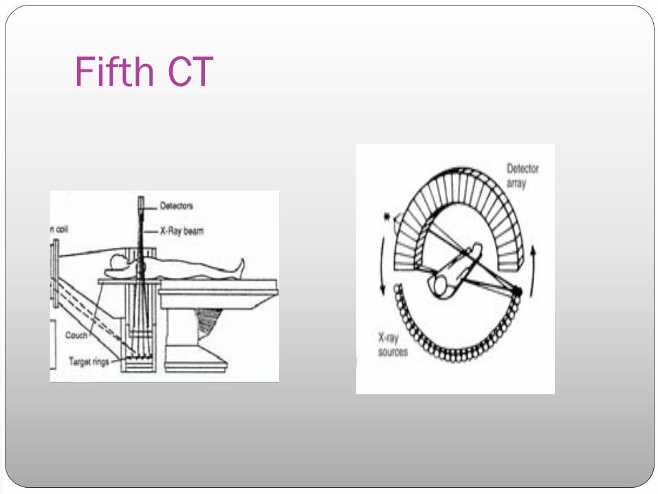
Design: x-ray tube is a large ring that circles patient, opposed to detector ringUse: for cardiac tomographic imaging “cine CT”X - rays produced = high - energy electron beamNo moving parts to this scanner gantryIt is capable of 50 - millisecond scan times and can produce 17 CT slices/secondstationary/stationary geometry
Fifth CT
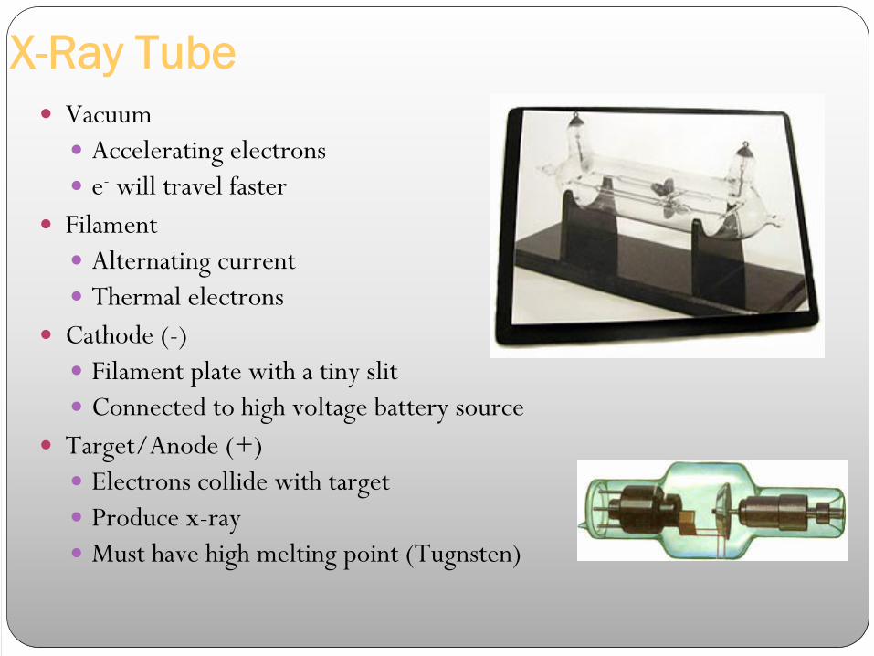
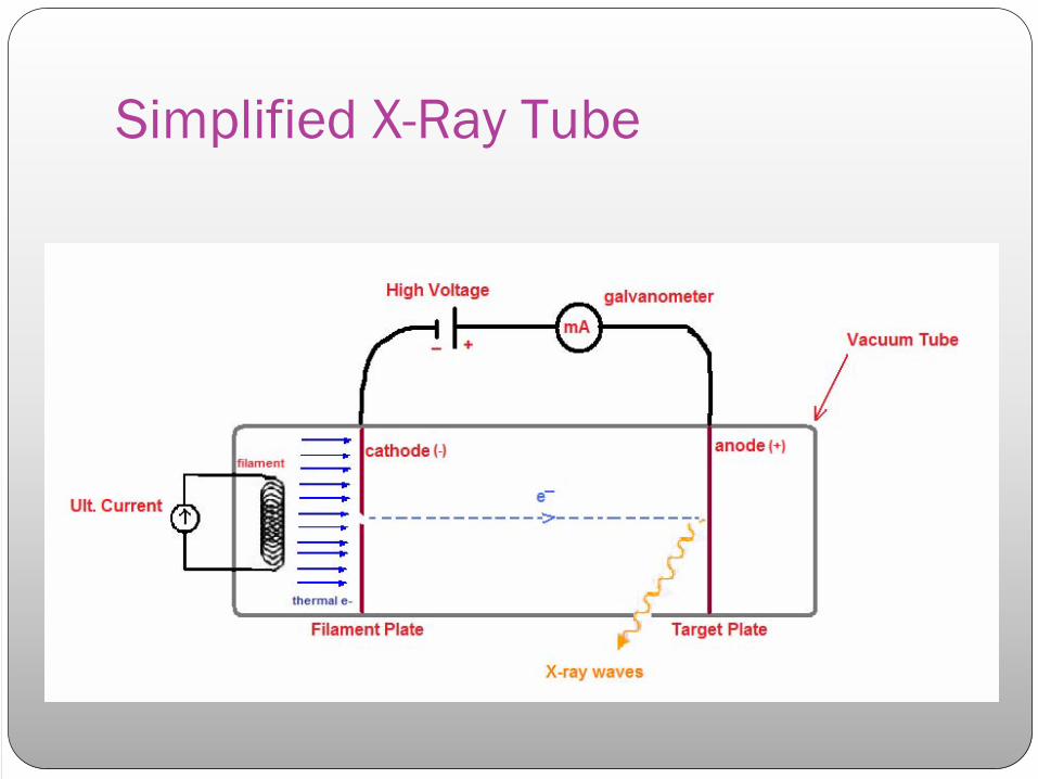
X-Ray TubeVacuum
Accelerating electrons e- will travel faster
FilamentAlternating currentThermal electrons
Cathode (-)Filament plate with a tiny slitConnected to high voltage battery source
Target/Anode (+)Electrons collide with targetProduce x-rayMust have high melting point (Tugnsten)
Simplified X-Ray Tube
The cine CT systemNo mechanical scanning motionX-ray detector and tube anode are stationaryAnode, is a very large semicircular ring that forms an arc around the patient scan circle Source of X-rays is moved around the same path as a fourth generation CT scanner by steering an electron beam around the X-ray anodeTerms millisecond CT, ultrafast CT and electron beam CT have also been used, although the latter can be confusing since the term suggests that the patient is exposed to an electron beam

Cont.Very fast scanner ,data collection for 1slice is 50-100 msRequires no mechanical motion to acquire dataSweeps an intense electron beam across a large, stationary anode target which surrounds the patientX-rays are emitted from the point where electrons strike targetX-rays transmitted through object are measured by a stationary array of detectorsCine CT systems, have higher noise level and lower spatial resolution but are ideal for some clinical application
cardiac imaging with and without the use of contrast agents, lung imaging, and paediatric studies
Sixth Generation
1990,Significant advancement in technologyAllowed 3D image acquisition within a single breath hold
Spiral/Helical CTDesign: x-ray tube rotates as patient is moved smoothly into x-ray scan fieldSimultaneous source rotation, table translation and data acquisitionProduces one continuous volume set of data for entire regionData for multiple slices from patient acquired at 1sec/slice

Spiral CT
Advantages of SpiralSpeed: patient movement continuous…………shorter exam time ; entire abdomen or chest: 30 sec (1BH)
Improved detections: differences in BHs in standard CT, small lesions fall out of plane for each continuous slice
Improved contrast: image a region in a short period, contrast can be timed
Improved reconstruction & manipulation:volume of data collected, transverse data can be reconstructed in any plane- strip away skin, muscles, etc….

Spiral/Helical CTThree technological developments: 1.
Slip-ring gantry designs
2.
Very high power x-ray tubes3.
Interpolation algorithms to handle projection data

1. Slip-Ring TechnologyAlternative to cabling system = slip-ring
1989 KalenderElectromechanical devices: circular electrical conductive rings and brushesTransmit electrical energy across a moving interfaceAll power and control signals from the stationary parts of the scanner system are communicated to the rotating frame through slip ringAllow scan frame to rotate continuously with no need to stop between rotations to rewind system cables

Slip Ring
2. High Power X-ray TubeThermal load in CT
1st and 2nd, stationary tube(low heat, slow scans)
Oil cooling thermal systems around tube, fast scans
scan time vs. Heat capacity increased x 5thermal demands on the x-ray tubeTubes with much higher thermal capacities were required to withstand continuous operation over multiple rotations
New design: ceramic insulators ,oil cooling of bearing, compact metal envelop
Expected life of tube 10,000-40,000 hrs vs. 1000 regular one

3. Interpolation AlgorithmsKalender developed interpolation methods to generate projections in a single planeOverlapping sections generated by math, not beam, improve z-axis with no increase in doseImproved image quality

Seventh GenerationNew Technology, single row had its limitation
Design: multiple detector array
The collimator spacing is wider and more of the x-rays that are produced by the tube are used in producing image data
Opening up the collimator in a single array scanner increases slice thickness, reducing spatial resolution in the slice thickness dimensionWith multiple detector array scanners, slice thickness is determined by detector size, not by the collimator
Seventh Generation CT“turbo-charged” spiral
Up to 8 rows of detectors
4 rows, large volume of patient scanned 1 BH
(thorax, abdomen, pelvis) at once
Allows 1mm sections though chest in 20 sec
Improvement in details
Problem with PACS, stain on storage system

Seventh CT

Seventh CTCone Beam & multiple parallel rows of detectors
Widened (z-direction) x ray beam & detector array to acquire multiple (4-64 slices simultaneously)
Advantage: reducing scan time/ increase z-resolution
Disadvantage: less scatter rejection compared to single slice, very expensive

Multiscanning
Relates to the technique of double or triple rotation of the tube and detectors around the same axial plane
Provides double of triple the volume per slice, upon which the final image can be derived
In practice each rotation produces its own bank of raw data,
Hence motion which may occur during one rotation can be averaged out from data of the remaining two rotations
Multiscanning therefore reduces motion artifacts and consequently improves image quality

MSCT1998 all major manufacturers introduced multislice CT, simultaneous acquisition of four slices, providing a great improvement.
4 slice, not fast enough to avoid venous overlay assuming a cerebral circulation time of less than 5 sec
In 2000, 8 slice CT were presented, followed by 16 slice in 2001
Most modern generation of MSCT is 64 slices per rotation, enabling a whole body CTA with 1,500mm scan range in 22-25seconds
Future announced 256slices
Components: tubes and detector measurement systems, large influence on performance
Development in software and computer capacity lead to processing and reconstruction in a short time

Seventh CT

Multiple Array Design
Combination of Section width

5th, 6th , 7th
G CT
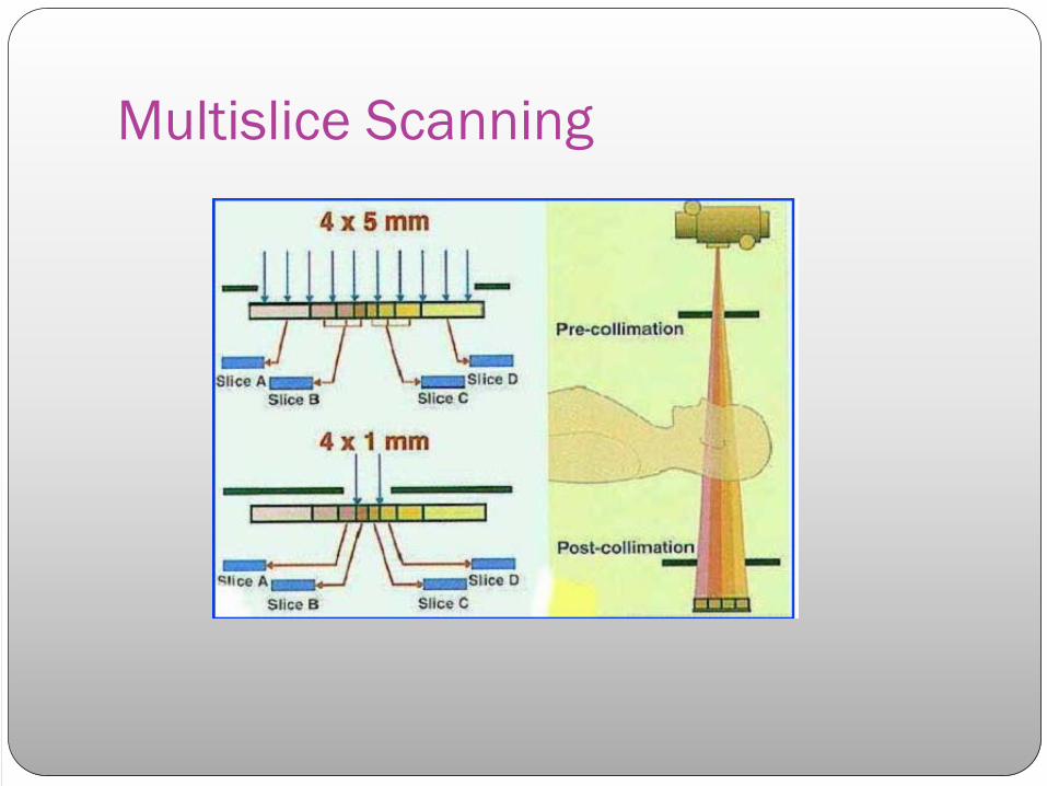
Multislice
Scanning
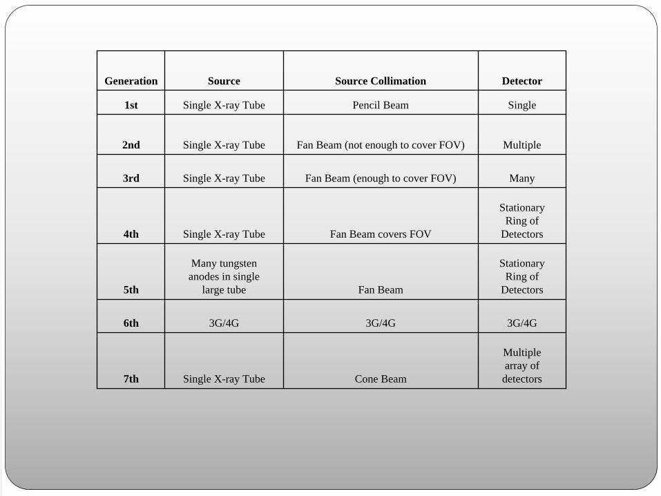
Generation Source Source Collimation Detector
1st Single X-ray Tube Pencil Beam Single
2nd Single X-ray Tube Fan Beam (not enough to cover FOV) Multiple
3rd Single X-ray Tube Fan Beam (enough to cover FOV) Many
4th Single X-ray Tube Fan Beam covers FOV
StationaryRing of
Detectors
5th
Many tungstenanodes in single
large tube Fan Beam
StationaryRing of
Detectors
6th 3G/4G 3G/4G 3G/4G
7th Single X-ray Tube Cone Beam
Multiplearray ofdetectors

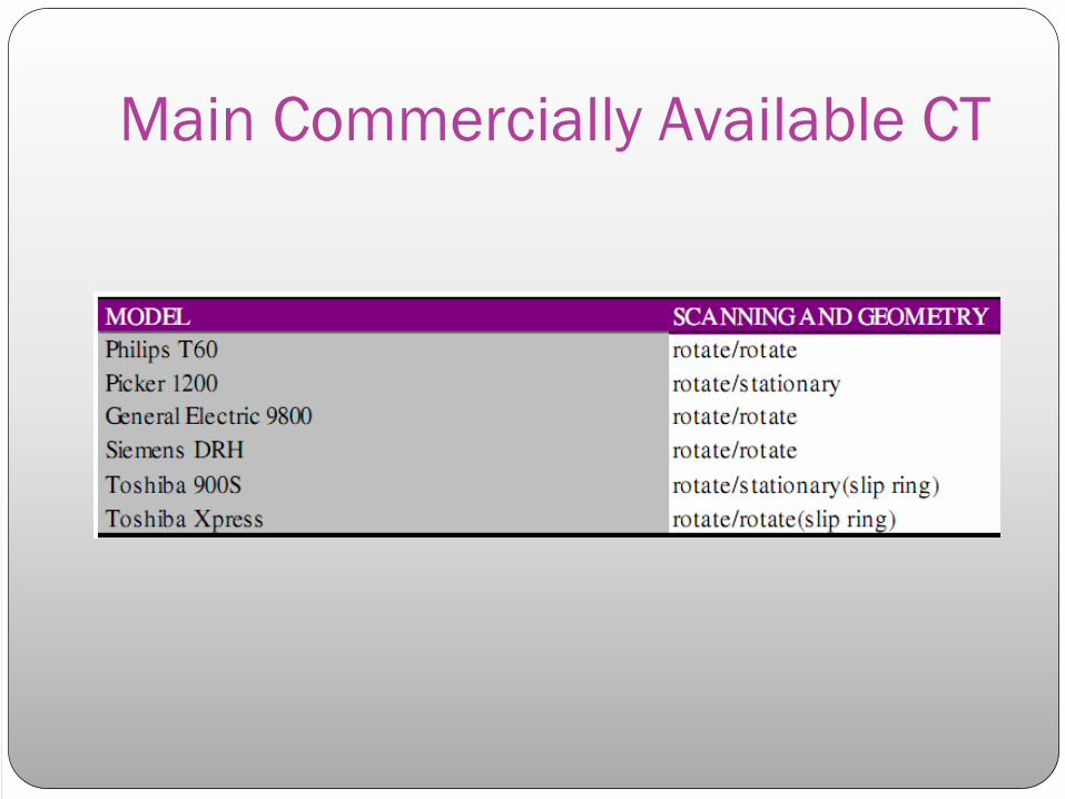
Main Commercially Available CT