csee journal of power and energy systems, vol. 1, no. …
TRANSCRIPT
CSEE JOURNAL OF POWER AND ENERGY SYSTEMS, VOL. 1, NO. 1, MARCH 2015 1
Modeling and Control of a V2G Charging StationBased on the Synchronverter Technology
Dongqi Liu, Qing-Chang Zhong, Fellow, IEEE, Yaonan Wang, and Guorong Liu
Abstract—In this paper, an idea of modeling and control of aV2G charging station (CS) for electric vehicles (EVs) by usingsynchronverter technology is proposed. Firstly, the architectureof the CS is introduced, which is composed of several CSunits connected in parallel and using synchronverters, whichare inverters that mimic synchronous machines, as the AC/DCinterfaces between each CS units and the grid. Then, a T-Sfuzzy controller is designed to decide the reference real power ofthe synchronverter by considering the grid frequency, which isestimated by the synchronverter itself, and the energy demand ofEVs inside each CS unit. Due to the inner frequency- and voltage-drooping mechanisms of the synchronverter, the input&ouputreal and reactive power of the CS will be automatically adjustedon the basis of the reference value according to the degree ofdeviation from the nominal value of the grid frequency andvoltage. To ensure the safety of this operation, an adaptivefrequency droop coefficient mechanism is designed to adapt thechange of the total energy storage of a CS unit by changingthe slope of the P-f control characteristic of the synchronverter.By using the proposed method, a CS can be integrated into thepower grid and behave in the same way as large synchronousgenerator&motor do, thus the CS and the power grid can be heldas a whole based on the well-known synchronous mechanism. Itis able to provide the grid damping and inertia, which wouldhelp the operation of the grid be smoother, and is able to notonly realizing bi-directional charging for electric vehicles but alsoproviding high-quality frequency and voltage regulation servicesfor the grid. The performance of the CS with the proposed controlstrategy is investigated with EVs of different battery states,different user’s sets and under different grid status. Simulationresults demonstrate that the proposed strategy can not onlyeffectively perform controlled charging/discharging of each singleelectric vehicle inside the CS, but can improve the performance ofthe electricity grid in terms of efficiency, stability, and reliabilityas well.
Index Terms—Electric vehicle(EV), Synchronverter, Vehicle-to-Grid(V2G), Smart Grid, Virtual Synchronous Machines(VSM).
I. INTRODUCTION
Manuscript received xx xx, 20xx; revised xx xx, 20xx. The work of D.Liuwas supported by the China Scholarship Council under Grant 201506130036,with the award of a scholarship (2015-2016).
D. Liu is with the School of Electrical and Information Engineering,Changsha University of Science&Technology, Changsha, 410114 China andthe College of Electrical and Information Engineering, Hunan University,Changsha, 410082 China. He was with the Department of Electrical andComputer Engineering, Illinois Institute of Technology, Chicago, IL 60616USA (e-mail: [email protected]).
Q. Zhong is with the Electrical and Computer Engineering Depart-ment, Illinois Institute of Technology, Chicago, IL 60616 USA (e-mail:[email protected]).
Y. Wang is with the College of Electrical and Information Engineering,Hunan University, Changsha, 410082 China (e-mail: [email protected]).
G. Liu is with the School of Computer and Communication, Hunan Instituteof Engineering, Xiangtan 411104 China (email: [email protected]).
ELECTRIC vehicles (EVs) will play a vital role in future’stransportation systems since this technology is promising
for both energy security and environment. One vital issue is thatwhether nowadays’ power grid can sustain the growing demanddue to the growing number of EVs and by what method tocharge these vehicles. To address these concern, in recent years,many researchers have studied the ’V2G’ technology[1]-[3],which means EVs serve in both charge and discharge modeand realize bi-directional power flow between cars and powerlines. Former studies[1]-[15] have shown that, V2G system isable to provide additional opportunities for grid operators, suchas reactive power support[6], active power regulation, loadbalancing by valley filling and peak load shaving[7][8], andis able to provide ancillary services such as frequency controland spinning reserves[9]-[12] so that the grid efficiency[13]-[15] is improved. These studies, however, are mainly focusedon the power system scheduling with aggregated EVs, whichlargely depends on the communication between the IndependentSystem Operator (ISO) and the EV aggregators, and lacknecessary study for low-level control.
Usually, EVs are connected to the power grid through powerelectronic converters. So does all kinds of renewable energysources. In general, when the penetration of EVs and renewablesources are relatively low, the stability of the power grid canbe held by the large synchronous generator which is widelyused in conventional thermal power plants or hydro powerplants. However, as the trend of EVs and renewable sources’penetration is going high in futures’ power grid, the largesynchronous generator is likely no longer able to hold thestability of the whole power grid. The key problem is, the powerelectronic converter, which is widely used as the interfacefor EVs and renewables to plug in the power grid, lacksdamping and inertia and does not have the same synchronouscharacteristic as the synchronous generator does. Hence, whenthe penetration of EVs and renewables is high, the power gridmight lose its’ robustness when power fluctuation and failureoccurs. To address the problem, Researchers have proposed a so-called ’virtual synchronous machine (VSM)’ [16][17] methodto control the power electronic converter so that it can mimicthe dynamic characteristic of a real synchronous machine. Syn-chronverter[18] is a kind of VSM. It’s’ controller has embeddedthe same mathematical model of a real synchronous machineso that a grid-connected synchronverter can behave like a realgrid-connected synchronous machine and is able to realizeautonomous frequency and voltage regulation for the griddue to its’ inner frequency- and voltage- drooping mechanism.Additionally, it is worth mention that synchronverter technologyis a voltage-controlled strategy, converters equipped by which

CSEE JOURNAL OF POWER AND ENERGY SYSTEMS, VOL. 1, NO. 1, MARCH 2015 2
are able to provide voltage support to the grid when the grid isweak while conventional current-controlled strategies(for eg.,PQ control strategy) are not able to[19].
In this paper, an original control method is proposed to con-trol the bi-directional converters of a V2G supporting chargingstation(CS) based on the synchronverter technology[18][19].The CS is composed of several CS units connected in paralleland using synchronverters as the AC/DC interfaces betweeneach CS units and the grid. A T-S fuzzy controller is designed todecide the reference set power of the synchronverter, which alsotranslates the real power-frequency (P-f) control characteristiccontrol characteristic of the synchronverter, by considering thegrid frequency (which is estimated by the synchronverter itself)and the battery status of each individual EV inside the unit; Anadaptive frequency drooping coefficient mechanism is designedto modify the imaginary mechanical friction coefficient toadapt the change of the energy capacity of the DC bus. Apower distribution strategy is proposed to distribute the totalreal power of a CS unit to every EVs inside it and ensurethe charging/discharging power of each EV is subject to its’maximum limit. By using the proposed method, a CS can beintegrated into the power grid and behave in the same wayas large synchronous machine do, so that the CS equippedwith the proposed control strategy and the power grid canbe held as a whole, hence the power system itself is morerobust to disturbance such as frequency fluctuation or failure.It has already been demonstrated by over 100 years operationin the power system that the synchronization mechanism ofsynchronous machines is able to hold the stability of the powersystem. Additionally, a synchronverter based V2G chargingstation adds damping and inertia to the power grid, whichwould help the operation of the grid be more smoother[19].This characteristic is vital when the penetration level of EVsis large. The proposed CS is able to not only realizing smartbi-directional charging control of electric vehicles regardingEVs’ SoC and grid status but also providing high-qualityfrequency and voltage regulation services for the grid dueto the inner frequency- and voltage-drooping mechanisms ofthe synchronverter.
The rest of this paper is organized as follows. Section2 introduced the structure and the basic idea of operatingthe proposed V2G charging station(CS). The synchronvertertechnology is overviewed in Section 3. Section 4 proposed asynchronverter-based control strategy for the proposed V2Gcharging station, where a T-S fuzzy controller is designed togenerate the reference set power of the synchronverter, and anadaptive drooping coefficient mechanism is proposed to ensurethe safety of the frequency droop operation. Additionally, apower distribution strategy is proposed for control of powerflow between different EVs. The performance of the proposedstrategy is tested by simulations in the different scenario andthe results are discussed in Section 5. Finally, conclusions aregiven in section 6.
II. MODELING OF A V2G CHARGING STATION FORELECTRIC VEHICLES
The proposed V2G charging station (CS) for electric vehiclesis composed of several CS units connected in parallel, where
a CS unit is consist of three subunits: Control Unit (CU),Synchronverter (SV), and DC Unit. SV is functioned as abi-directional converter that combines the grid and the DCunit, its’ reference set power and imaginary mechanical frictioncoefficient is determined by the control unit, which is composedof four parts: capacity calculation unit, T-S fuzzy control unit,and power distribution unit, and adaptive drooping coefficientunit; DC unit is composed of a DC bus, several EVs thatconnected to the DC bus, and DC-DC converters. The layoutof a CS unit is as Fig.1 shown. The operation process of aproposed CS unit is summarized as follows:
Synchronverter
DC/DCConverter
DC/DCConverter
...
...
T-S Fuzzy Controller
Capacity Calculation2G VE
Power Distribution
gridf
1EVP EVnP
1EV
nEV
1EVSoC
EVnSoC
...
...
...Adaptive Drooping
coefficient
pD
pD
11, ar EE
anrn EE ,
setPsetP
1limSoC nSoClim...
Fig. 1. Conceptual system framework
1) All the information of EVs’ state ofcharge (SoC1, SoC2, · · ·, SoCn) and constraints(SoCmin1, SoCmin2, · · ·, SoCminn)(where SoCminiare the lower SOC limit of EV batteries defined by EV users)are collected and send to the capacity calculation unit of theCCU;
2) The capacity calculation unit of the CCU count out theindividual available energy (Ea1, Ea2, · · ·, Ean) as well asthe individual required energy (Er1, Er2, · · ·, Ern) of eachEVs’ batteries and then calculate out the total available energy(EV 2G) and the total required energy (EG2V ) of the CS unit;
3) Based on the grid frequency (fgrid) (which is estimatedby the synchronverter itself) and the total required energy(EG2V ), the T-S fuzzy controller calculate out the referenceset power (Pset) of the CS unit;
4) According to the total available energy (EV 2G), select aproper frequency drooping coefficient of the synchronverter;
5) According to the result of T-S fuzzy controller Pset and theselected frequency drooping coefficient of the synchronverter,according to the individual available energy (Eai, the individualrequired energy (Eri, as well as the maximum power limitof each EVs, calculate out the reference charging/dischargingpower (PEV 1, PEV 2, · · ·, PEV n) of each EVs and the final setpower P
′
set of the synchonverter simultaneously;6) According to the calculation results in step 4 and step5, set
and run the synchronverter to realize the autonomous interactionbetween the CS and the grid.
CSEE JOURNAL OF POWER AND ENERGY SYSTEMS, VOL. 1, NO. 1, MARCH 2015 3
BAT
Ls
Ls
Ls
C1
DC+
DC-
+
Ea
Eb
Ec
VT1
VT2
VT3
VT4
VT5
VT6
VT7
VT8
L1
Rs
Rs
Rs
ia
ib
ic
VtCCC
Lg
Lg
Lg
ga
gb
Vgc
Va
Vb
Vc
+
L1
Vga
Vgb
Vgc
Rs
Rs
Rs
Ls
Ls
Ls
CCC
Rg
Rg
Rg
Lg
Lg
Lg
DC+
DC-
C1
VT7
VT8
BAT
Vt
VT5
VT6
VT3
VT4
VT1
VT2
Ea
Eb
Ec
ia
ib
ic
Circuit Breaker
Vga
Vgb
Vgc
Rs
Rs
Rs
Ls
Ls
Ls
CCC
Rg
Rg
Rg
Lg
Lg
Lg
+
-
VT5
VT6
VT3
VT4
VT1
VT2
ia
ib
ic
Circuit Breaker
ae
be
ce
av
bv
cvDCV
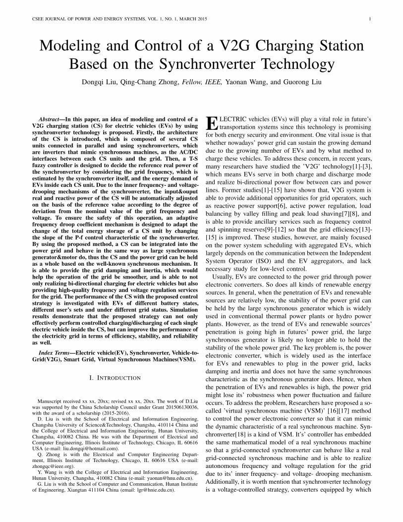
Fig. 2. Power Part of a Synchronverter
,f fR L
,s sR L ,s sR L
,s sR L
ai
bi ci
fi
av
bv cv
fv
M
a-axis
b-axis c-axis
Fig. 3. Structure of an idealized three-phase round-rotor synchronous machine
III. OVERVIEW OF THE SYNCHRONVERTER TECHNOLOGY
In this paper, synchronverters, which are converters thatmimic synchronous machines[18][19], is introduced and oper-ated here as the bi-directional DC-AC converter between theDC bus and the grid. The power part of a synchronverter is asFig.2 shown. Imaging that the inductance Ls and resistanceRs of the LC filter are the impedance of stator windingsof an imaginary synchronous generator(SG) as Fig.3 shown,the capacitor voltage [va, vb, vc]
T is the terminal voltage ofthe SG, the inductor current [ia, ib, ic]
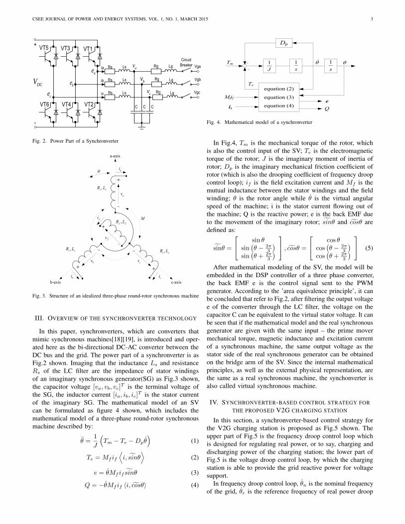
T is the stator currentof the imaginary SG. The mathematical model of an SVcan be formulated as figure 4 shown, which includes themathematical model of a three-phase round-rotor synchronousmachine described by:
θ =1
J
(Tm − Te −Dpθ
)(1)
Te = Mf if
⟨i, sinθ
⟩(2)
e = θMf if sinθ (3)
Q = −θMf if 〈i, cosθ〉 (4)
s
1
J
1
s
1
Dp
equation (2)
e
Tm
Mfif
is
Te
Q
-
-
equation (3)
equation (4)
Fig. 4. Mathematical model of a synchronverter
In Fig.4, Tm is the mechanical torque of the rotor, whichis also the control input of the SV; Te is the electromagnetictorque of the rotor; J is the imaginary moment of inertia ofrotor; Dp is the imaginary mechanical friction coefficient ofrotor (which is also the drooping coefficient of frequency droopcontrol loop); if is the field excitation current and Mf is themutual inductance between the stator windings and the fieldwinding; θ is the rotor angle while θ is the virtual angularspeed of the machine; i is the stator current flowing out ofthe machine; Q is the reactive power; e is the back EMF dueto the movement of the imaginary rotor; sinθ and cosθ aredefined as:
sinθ =
sin θsin(θ − 2π
3
)sin(θ + 2π
3
) , cosθ =
cos θcos(θ − 2π
3
)cos(θ + 2π
3
) (5)
After mathematical modeling of the SV, the model will beembedded in the DSP controller of a three phase converter,the back EMF e is the control signal sent to the PWMgenerator. According to the ’area equivalence principle’, it canbe concluded that refer to Fig.2, after filtering the output voltagee of the converter through the LC filter, the voltage on thecapacitor C can be equivalent to the virtual stator voltage. It canbe seen that if the mathematical model and the real synchronousgenerator are given with the same input – the prime movermechanical torque, magnetic inductance and excitation currentof a synchronous machine, the same output voltage as thestator side of the real synchronous generator can be obtainedon the bridge arm of the SV. Since the internal mathematicalprinciples, as well as the external physical representation, arethe same as a real synchronous machine, the synchonverter isalso called virtual synchronous machine.
IV. SYNCHRONVERTER-BASED CONTROL STRATEGY FORTHE PROPOSED V2G CHARGING STATION
In this section, a synchronverter-based control strategy forthe V2G charging station is proposed as Fig.5 shown. Theupper part of Fig.5 is the frequency droop control loop whichis designed for regulating real power, or to say, charging anddischarging power of the charging station; the lower part ofFig.5 is the voltage droop control loop, by which the chargingstation is able to provide the grid reactive power for voltagesupport.
In frequency droop control loop, θn is the nominal frequencyof the grid, θr is the reference frequency of real power droop

CSEE JOURNAL OF POWER AND ENERGY SYSTEMS, VOL. 1, NO. 1, MARCH 2015 4
1
nmT
T
pD r
eT
rV
mVqD Sq
Q1
Ksf fM i
si
sin
1
Js
cos1-
e
Adaptive Self-Synchronized Synchronverter
Circuit Breaker
avbv
cv
ai bi ci
LCLFilter
PI
+
+
+
+
nSp
Adaptive mechanism
DC BUS
EV2G
Pset
Qset
Fig. 5. Control of a Synchronverter(SV)
control, a PI controller is adopted to regulate the output∆T of the frequency droop block to be 0 and to generatea small ∆θr, ∆θr is then added to the nominal frequencyθr so that θr is generated which is nearly the same as thegrid frequency. Detail demonstration of this self-frequencytracking performance can be found in the literature[20]. Basedon this self-frequency tracking performance, an SV do notneed a dedicated synchronization unit, for e.g., a phase-lockedloop(PLL), to provide phase references. This have simplify theoperation of controller, reduced cost and free of control errorcaused by the use of PLL.Dp is the drooping coefficient offrequency droop control, which is defined as:
Dp = −∆T
∆θ≈ ∆P
∆θ · θn=
Pn · x%(θn
)2· y%
(6)
Where Pn is the rated real power of synchronverter, θn is thenominal grid frequency, the physical meaning of equation (6)is: a drop of x% of grid frequency cause the torque(also thereal power) increase by x%.
J is the virtual inertia of rotor, which is defined by Dp andthe time constant of frequency loop τf :
J = Dpτf (7)
In voltage droop control loop, Vn is the nominal value of gridvoltage amplitude, Vm is the amplitude of grid voltage, whichis calculated by (assuming the terminal voltage are balanced):
VaVb + VbVc + VcVa = −3
4V 2m (8)
Dq is defined as the ratio of the required change of reactivepower ∆Q to the change of voltage ∆v:
Dq = −∆Q
∆V=Qn · x%
Vn · y%(9)
Where Qn is the rated reactive power of synchronverter, thephysical meaning of equation (9) is: a drop of y% of gridvoltage causes the reactive power increase by x%.
P
Pset P-Set Mode
P-Droop Mode
n0
Q
Q-Set Mode
Q-Droop Mode
0nV mV
Qset=0
Fig. 6. P-f and Q-V control characteristic of the synchronverter
The error between the reference value Qref and the reactivepower Q is fed into an integrator with a gain 1/K to generateMf if , where K is defined by Dq , nominal grid frequency θnand the time constant of voltage loop τv:
K = θnDqτv (10)
The real power-frequency (P-f) control characteristic andreactive power-voltage (Q-V) control characteristic of thesynchronverter is as Fig.6 shown.
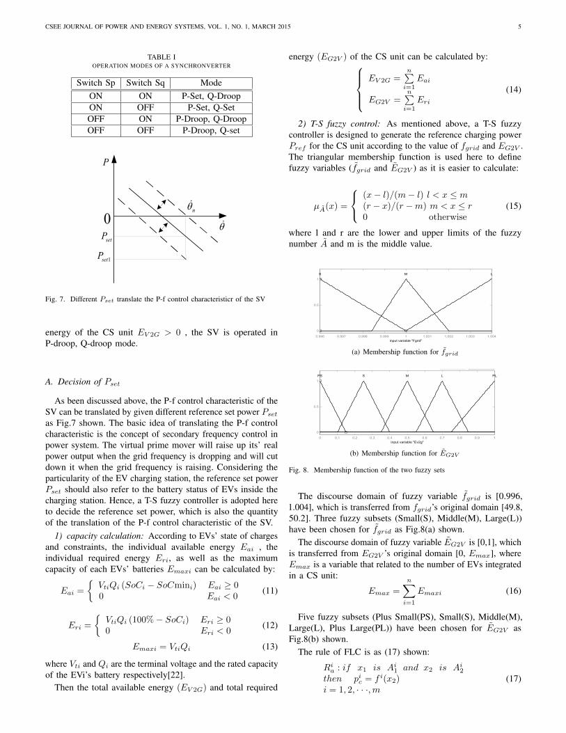
It can be seen from Fig.6, when SV work in P-set mode, theoutput power of SV track the reference Pset, which means thepower output of the virtual prime mover; when synchronverterwork in P-droop mode, the output power of SV is a linearfunction of the grid frequency. The slash shown in fig.6 will betranslated according to the position of the reference Pset. Dp
is the slope of the slash. Obviously, a greater Dp means thesame frequency change would cause larger real power changein response. Q-set mode and Q-droop mode are similar to P-setmode and P-droop mode, no more tautology here.
Different operation modes of the SV can be selected by turnon or off switches shown in table 2. In this paper, when the gridfrequency is higher than its nominal value, the synchronverteris operated in P-set, Q-droop mode; When the grid frequency isequal to or lower than its nominal value, and the total available
CSEE JOURNAL OF POWER AND ENERGY SYSTEMS, VOL. 1, NO. 1, MARCH 2015 5
TABLE IOPERATION MODES OF A SYNCHRONVERTER
Switch Sp Switch Sq ModeON ON P-Set, Q-DroopON OFF P-Set, Q-SetOFF ON P-Droop, Q-DroopOFF OFF P-Droop, Q-set
0
P
n
setP
1setP
Fig. 7. Different Pset translate the P-f control characteristicr of the SV
energy of the CS unit EV 2G > 0 , the SV is operated inP-droop, Q-droop mode.
A. Decision of Pset
As been discussed above, the P-f control characteristic of theSV can be translated by given different reference set power Psetas Fig.7 shown. The basic idea of translating the P-f controlcharacteristic is the concept of secondary frequency control inpower system. The virtual prime mover will raise up its’ realpower output when the grid frequency is dropping and will cutdown it when the grid frequency is raising. Considering theparticularity of the EV charging station, the reference set powerPset should also refer to the battery status of EVs inside thecharging station. Hence, a T-S fuzzy controller is adopted hereto decide the reference set power, which is also the quantityof the translation of the P-f control characteristic of the SV.
1) capacity calculation: According to EVs’ state of chargesand constraints, the individual available energy Eai , theindividual required energy Eri, as well as the maximumcapacity of each EVs’ batteries Emaxi can be calculated by:
Eai =
VtiQi (SoCi − SoCmini) Eai ≥ 00 Eai < 0
(11)
Eri =
VtiQi (100%− SoCi) Eri ≥ 00 Eri < 0
(12)
Emaxi = VtiQi (13)
where Vti and Qi are the terminal voltage and the rated capacityof the EVi’s battery respectively[22].
Then the total available energy (EV 2G) and total required
energy (EG2V ) of the CS unit can be calculated by:EV 2G =
n∑i=1
Eai
EG2V =n∑i=1
Eri
(14)
2) T-S fuzzy control: As mentioned above, a T-S fuzzycontroller is designed to generate the reference charging powerPref for the CS unit according to the value of fgrid and EG2V .The triangular membership function is used here to definefuzzy variables (fgrid and EG2V ) as it is easier to calculate:
µA(x) =
(x− l)/(m− l) l < x ≤ m(r − x)/(r −m) m < x ≤ r0 otherwise
(15)
where l and r are the lower and upper limits of the fuzzynumber A and m is the middle value.
FIS Variables
Fgrid
Eg2v
f(u)Power
0.996 0.997 0.998 0.999 1 1.001 1.002 1.003 1.0040
0.5
1
Membership function plots
input variable "Fgrid"
S M L
(a) Membership function for fgrid
FIS Variables
Fgrid
Ev2g
f(u)Power
0 0.1 0.2 0.3 0.4 0.5 0.6 0.7 0.8 0.9 10
0.5
1
Membership function plots
input variable "Ev2g"
PS M PLLS
(b) Membership function for EG2V
Fig. 8. Membership function of the two fuzzy sets
The discourse domain of fuzzy variable fgrid is [0.996,1.004], which is transferred from fgrid’s original domain [49.8,50.2]. Three fuzzy subsets (Small(S), Middle(M), Large(L))have been chosen for fgrid as Fig.8(a) shown.
The discourse domain of fuzzy variable EG2V is [0,1], whichis transferred from EG2V ’s original domain [0, Emax], whereEmax is a variable that related to the number of EVs integratedin a CS unit:
Emax =
n∑i=1
Emaxi (16)
Five fuzzy subsets (Plus Small(PS), Small(S), Middle(M),Large(L), Plus Large(PL)) have been chosen for EG2V asFig.8(b) shown.
The rule of FLC is as (17) shown:
Ria : if x1 is Ai1 and x2 is Ai2then pic = f i(x2)i = 1, 2, · · ·,m
(17)
CSEE JOURNAL OF POWER AND ENERGY SYSTEMS, VOL. 1, NO. 1, MARCH 2015 6
TABLE IIRULE BASE FOR FLC
fgrid EG2V λia λib fgrid EG2V λia λibS PS 1 0 M L 0 0.8S S 0 0.3 M PL 0 1S M 0 0.5 L VS 1 0S L 0 0.5 L S 0 0.5S PL 0 0.8 L M 0 0.5M PS 1 0 L L 0 0.8M S 0 0.3 L PL 0 1M M 0 0.5
where x1 = fgrid, x2 = EG2V , Ai1 ∈ fgrid, Ai2 ∈ EG2V .pic is the charging power of the CS unit determined by rule i,which is designed here as a linear function of EG2V :
pic = f i(x2) =λiaT0EG2V + λibnPcm (18)
where n is the number of EVs in the CS unit, Pcm is thenominal charging power of electric vehicles, T0 is a timeconstant, which can be calculated by:
T0 =MAX(Emaxi)
Pcn(19)
λia ∈ [0, 1] and λib ∈ [0, 0.3, 0.5, 0.8, 1] are constants whichvalue are determined by the value of EG2V and fgrid. If therequired energy EG2V is very small, then λia equals to 1 andλib equals to 0 so that pic is able to track the change of EG2V ,hence the battery of EVs won’t be overcharged; If EG2V isnot very small, λia equals to 0 and λib equals to 1 so that thevalue of pic is self-adjusted according to EG2V and fgrid. Therule base for selection of λia and λib is given in Table 1.
According to table 1, the output of FLC is formulated as:
Pset =
15∑i=1
pic2∏l=n
µAin(xn)
15∑i=1
2∏n=1
µAin(xn)
= f1(x1, x2)EG2V + f2(x1, x2)
(20)where f1(x1, x2) and f2(x1, x2) are non-linear functions:
f1(x1, x2) =
15∑i=1
λia
2∏n=1
µAin(xn)
15∑i=1
2∏n=1
µAin(xn)
· 1T0
f2(x1, x2) =
15∑i=1
λib
2∏n=1
µAin(xn)
15∑i=1
2∏n=1
µAin(xn)
· nPcm
(21)
After obtaining the current grid frequency and EV batterystatus at each sampling time, the reference charging power ofeach CS units can be calculated out by equation(20) and (21).
B. Adaptive frequency drooping coefficient
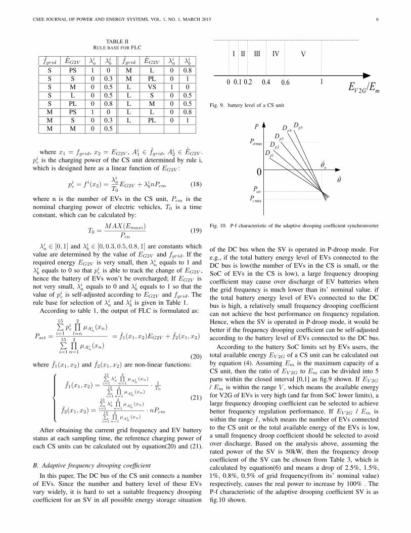
In this paper, The DC bus of the CS unit connects a numberof EVs. Since the number and battery level of these EVsvary widely, it is hard to set a suitable frequency droopingcoefficient for an SV in all possible energy storage situation
0
ⅤⅠ Ⅱ Ⅲ Ⅳ
mGV EE /210.60.40.20.1
Fig. 9. battery level of a CS unit
maxcP
maxdP
1pD2pD
3pD4pD 5pD
0
P
n
setP
Fig. 10. P-f characteristic of the adaptive drooping coefficient synchronverter
of the DC bus when the SV is operated in P-droop mode. Fore.g., if the total battery energy level of EVs connected to theDC bus is low(the number of EVs in the CS is small, or theSoC of EVs in the CS is low), a large frequency droopingcoefficient may cause over discharge of EV batteries whenthe grid frequency is much lower than its’ nominal value. ifthe total battery energy level of EVs connected to the DCbus is high, a relatively small frequency drooping coefficientcan not achieve the best performance on frequency regulation.Hence, when the SV is operated in P-droop mode, it would bebetter if the frequency drooping coefficient can be self-adjustedaccording to the battery level of EVs connected to the DC bus.
According to the battery SoC limits set by EVs users, thetotal available energy EV 2G of a CS unit can be calculated outby equation (4). Assuming Em is the maximum capacity of aCS unit, then the ratio of EV 2G to Em can be divided into 5parts within the closed interval [0,1] as fig.9 shown. If EV 2G
/ Em is within the range V , which means the available energyfor V2G of EVs is very high (and far from SoC lower limits), alarge frequency drooping coefficient can be selected to achievebetter frequency regulation performance. If EV 2G / Em iswithin the range I , which means the number of EVs connectedto the CS unit or the total available energy of the EVs is low,a small frequency droop coefficient should be selected to avoidover discharge. Based on the analysis above, assuming therated power of the SV is 50kW, then the frequency droopcoefficient of the SV can be chosen from Table 3, which iscalculated by equation(6) and means a drop of 2.5%, 1.5%,1%, 0.8%, 0.5% of grid frequency(from its’ nominal value)respectively, causes the real power to increase by 100% . TheP-f characteristic of the adaptive drooping coefficient SV is asfig.10 shown.
CSEE JOURNAL OF POWER AND ENERGY SYSTEMS, VOL. 1, NO. 1, MARCH 2015 7
TABLE IIIFREQUENCY DROOPING COEFFICIENT
Zone I II III IV VDp 20.26 33.77 50.66 63.33 101.3
C. Power Distribution
A power distribution strategy is designed to distribute theinput/output power of the SV to each EVs that connected tothe DC bus of the CS unit. The charging/discharging power ofthe EVs can be calculated by equation(22).
PEV i = Eri
EG2VPG2V + Eai
EV 2G
[Dpθn
(θ − θn
)]θg ≤ θn
PEV i = Eri
EG2VPG2V θg > θn
(22)where PEV i is the reference power of each electric vehicles
in the charging station. EV 2G and EG2V are the total availableand required energy of the CS unit, Eai and Eri are theavailable and required energy of each EV. By using theproposed strategy, the charging and discharging power of EVsare determined by the output of the fuzzy controller, gridfrequency, the frequency drooping coefficient, individual EVrequired or available energy as well as the proportion that therequired or available energy of each individual EV to the wholeCS unit.
For safety concern, in order to prevent PEV i exceed themaximum charging power Pcm, or the maximum dischargingpower Pdm, PEV i is subject to constraint as equation (23)shown:
PEV i = Pcm PEV i ≥ PcmPEV i = −Pdm PEV i < −Pdm
(23)
Finally, the real power setpoint of the synchronverter P′
set
turned out to be:
P′
set =
−
n∑i=1
PEV i +Dpθn
(θ − θn
)θ ≤ θn
−n∑i=1
PEV i θ > θn
(24)
D. DC-DC Converters
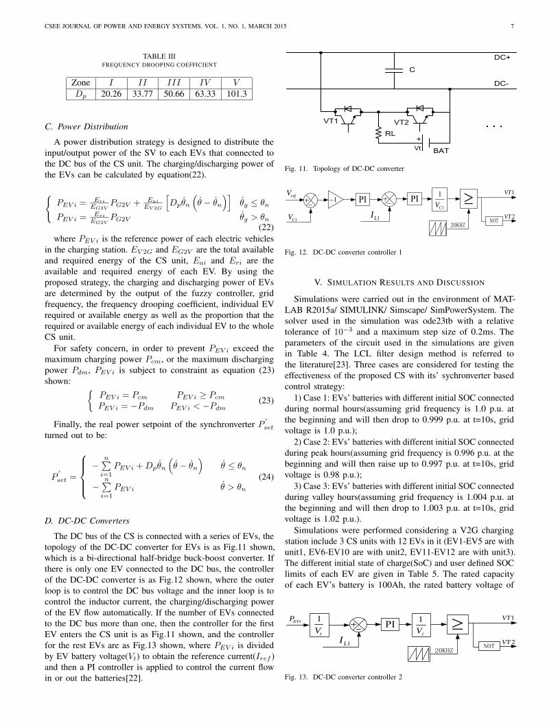
The DC bus of the CS is connected with a series of EVs, thetopology of the DC-DC converter for EVs is as Fig.11 shown,which is a bi-directional half-bridge buck-boost converter. Ifthere is only one EV connected to the DC bus, the controllerof the DC-DC converter is as Fig.12 shown, where the outerloop is to control the DC bus voltage and the inner loop is tocontrol the inductor current, the charging/discharging powerof the EV flow automatically. If the number of EVs connectedto the DC bus more than one, then the controller for the firstEV enters the CS unit is as Fig.11 shown, and the controllerfor the rest EVs are as Fig.13 shown, where PEV i is dividedby EV battery voltage(Vt) to obtain the reference current(Iref )and then a PI controller is applied to control the current flowin or out the batteries[22].
+RL
DC+
DC-C
VT1 VT2
BATVt
Fig. 11. Topology of DC-DC converter
1LI1CV
refV 1VT
20KHZ
PI PI1
1
CV NOT
2VT
1
Fig. 12. DC-DC converter controller 1
V. SIMULATION RESULTS AND DISCUSSION
Simulations were carried out in the environment of MAT-LAB R2015a/ SIMULINK/ Simscape/ SimPowerSystem. Thesolver used in the simulation was ode23tb with a relativetolerance of 10−3 and a maximum step size of 0.2ms. Theparameters of the circuit used in the simulations are givenin Table 4. The LCL filter design method is referred tothe literature[23]. Three cases are considered for testing theeffectiveness of the proposed CS with its’ sychronverter basedcontrol strategy:
1) Case 1: EVs’ batteries with different initial SOC connectedduring normal hours(assuming grid frequency is 1.0 p.u. atthe beginning and will then drop to 0.999 p.u. at t=10s, gridvoltage is 1.0 p.u.);
2) Case 2: EVs’ batteries with different initial SOC connectedduring peak hours(assuming grid frequency is 0.996 p.u. at thebeginning and will then raise up to 0.997 p.u. at t=10s, gridvoltage is 0.98 p.u.);
3) Case 3: EVs’ batteries with different initial SOC connectedduring valley hours(assuming grid frequency is 1.004 p.u. atthe beginning and will then drop to 1.003 p.u. at t=10s, gridvoltage is 1.02 p.u.).
Simulations were performed considering a V2G chargingstation include 3 CS units with 12 EVs in it (EV1-EV5 are withunit1, EV6-EV10 are with unit2, EV11-EV12 are with unit3).The different initial state of charge(SoC) and user defined SOClimits of each EV are given in Table 5. The rated capacityof each EV’s battery is 100Ah, the rated battery voltage of
1LI
EViP 1VT
20KHZ
PI1
tV NOT
2VT
1
tV
Fig. 13. DC-DC converter controller 2

CSEE JOURNAL OF POWER AND ENERGY SYSTEMS, VOL. 1, NO. 1, MARCH 2015 8
TABLE IVPARAMETERS OF THE SIMULATION CIRCUIT
Parameters Values Parameters ValuesLs 150 µH Lg 450 µHRs 0.045 Ω Rg 0.135 ΩC 22 µF R 1000 ΩLvr 1 mH Rvr 0.1 ΩCdc 10 mF Ldc 20 mHRdc 0.1 Ω Kp 0.02Ki 0.4 DC-bus voltage 700 V
grid rated 50 Hz nominal voltage 380 Vfrequency (line-line)
each EV is 300V. The power part of the charging stationincludes 3 parallel-operated SVs with 3 DC units connected toit. Assume the maximum charging and discharging power ofeach EV is Pcm=10kW, Pdm=-10kW; The rated real power ofeach synchronverter is 50kW, the rated reactive power of eachSV is 10kVar; The voltage drooping factor Dq was chosenas 644.6(which means a voltage droop of 5% will cause thereactive power to increase by 100%). The time factor of thedroop loops were chosen as τf = 0.002s and τv = 0.002s.
TABLE VBATTERIES SPECIFICATION IN DIFFERENT SCENARIO
i SoCmin Initial SoCCase1 Case2 Case3
EV1 10 50 50 50EV2 10 60 60 60EV3 10 70 70 70EV4 10 80 80 80EV5 10 95 95 95EV6 10 30 30 30EV7 10 40 40 40EV8 10 50 50 50EV9 10 80 80 80EV10 10 90 90 90EV11 10 60 60 60EV12 10 80 80 80
A. Case study
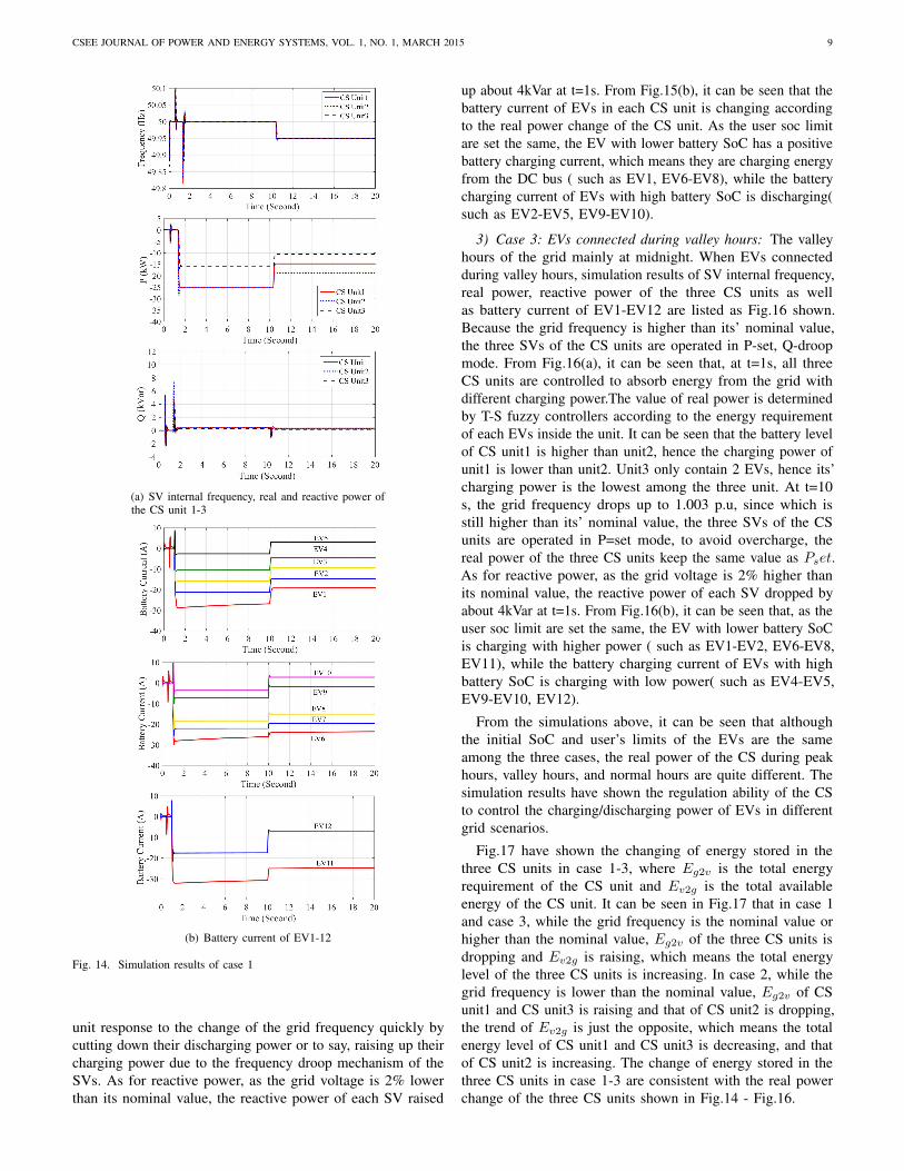
1) Case 1: EVs connected during normal hours: The periodwhen the power grid is neither in peak hour or in valley hourhere is called ’normal hour’. Assuming grid frequency is 1.0p.u., grid voltage is 1.0 p.u., simulation results of SV internalfrequency, real power, reactive power of the three CS unitsas well as battery current of EV1-EV12 are listed as Fig.14shown. From Fig.14(a), it can be seen that the three SVs werequickly synchronized with the grid before the circuit breakerswere turned on at t=0.5s. There was a tiny current surge onthe circuit when grid connect operation was applied at t=0.5s.Then, at t=1 s, the SVs were quickly responded to the realpower step change Pset(calculated by eq.19), since θ = θn,
the value of Pset is mainly determined by the output of theT-S fuzzy controller according to the battery level of EVs inthe charging station. It can be seen that, when EVs connectedduring normal hours, CS unit 1 to CS unit3 are all controlled tocharge from the grid. As there are only 2 EVs in CS unit3, thecharging power of unit3 is relatively lower than that of unit1and unit2. Then, at t=10 s, the grid frequency drop to 0.999p.u., it can be seen that the inner frequency of the SV trackthe grid frequency quickly, and the three CS unit responseto the change of the grid frequency quickly by cutting downtheir charging power due to the frequency droop mechanismof the SV. As for the reactive power, as the grid voltage is theequal to its’ nominal value, most of time the reactive powerof the three SV is the same as Qset which was always set as0. but at t=0.5s, and t=1s, Q faced a little fluctuation due tothe coupling between real and reactive power. From Fig.14(b),it can be seen that the battery current of EVs in each CS unitis changing according to the real power change of the CSunit. the EVs share the real power of the CS unit accordingto their own battery status: as the user soc limit are set thesame, the EV with lower battery SoC will gain more chargingpower (hence the battery charging current is higher) accordingto the proposed power distribution strategy( such as EV1-EV3,EV6-EV8, EV11), while the battery charging current of EVswith high battery SoC is relatively low( such as EV4-EV5,EV9-EV10, EV12).
2) Case 2: EVs connected during peak hours: When EVsconnected during peak hours, simulation results of SV internalfrequency, real power, reactive power of the three CS units aswell as battery current of EV1-EV12 are listed as Fig.15 shown.From Fig.15(a), it can be seen that the internal frequenciesof the three SVs were quickly synchronized with the gridfrequency. because the grid frequency is lower than its’ nominalvalue, the three SV are operated in P-droop, Q-droop mode, thefrequency drooping coefficient Dp will be adaptively selectedaccording to the battery status of EVs connected to the DCbuses of the SVs. It can be seen that, at t=1s, CS unit1 andCS unit3 are controlled to discharge energy to the grid, whileunit2 is controlled to charge from the grid. The value of thecharging/discharging power of the three CS unit are determinedboth by the T-S fuzzy controller and the frequency droopingmechanism of the SVs. As the battery level of CS unit1 isrelatively high, then a relatively high Dp is applied. Accordingto P-f characteristic of SV , when θ− θn < 0, the CS unit willreduce the charging power or discharge to the grid (depend onthe value of Pset). In this case, since the battery level of CSunit1 is relatively high, then the basic charging power of CSunit1 determined by the T-S fuzzy controller is relatively low,so a 0.4% deviation of grid frequency lead CS unit1 dischargeenergy to the grid. The energy stored in CS unit2 is lowerthan unit1, so it still charging from the grid. However, whencompared with case1, it can be seen that the charging powerof CS unit2 is greatly reduced, which is also due to the P-fcontrol characteristic of the SV. There are only 2 EVs in CSunit3, hence a relatively low Dp is applied. So the dischargingpower of CS unit3 is lower than that of unit1. Then, at t=10 s,the grid frequency raise up to 0.997 p.u.,the inner frequencyof the SV track the grid frequency quickly, and the three CS
CSEE JOURNAL OF POWER AND ENERGY SYSTEMS, VOL. 1, NO. 1, MARCH 2015 9
(a) SV internal frequency, real and reactive power ofthe CS unit 1-3
(b) Battery current of EV1-12
Fig. 14. Simulation results of case 1
unit response to the change of the grid frequency quickly bycutting down their discharging power or to say, raising up theircharging power due to the frequency droop mechanism of theSVs. As for reactive power, as the grid voltage is 2% lowerthan its nominal value, the reactive power of each SV raised
up about 4kVar at t=1s. From Fig.15(b), it can be seen that thebattery current of EVs in each CS unit is changing accordingto the real power change of the CS unit. As the user soc limitare set the same, the EV with lower battery SoC has a positivebattery charging current, which means they are charging energyfrom the DC bus ( such as EV1, EV6-EV8), while the batterycharging current of EVs with high battery SoC is discharging(such as EV2-EV5, EV9-EV10).
3) Case 3: EVs connected during valley hours: The valleyhours of the grid mainly at midnight. When EVs connectedduring valley hours, simulation results of SV internal frequency,real power, reactive power of the three CS units as wellas battery current of EV1-EV12 are listed as Fig.16 shown.Because the grid frequency is higher than its’ nominal value,the three SVs of the CS units are operated in P-set, Q-droopmode. From Fig.16(a), it can be seen that, at t=1s, all threeCS units are controlled to absorb energy from the grid withdifferent charging power.The value of real power is determinedby T-S fuzzy controllers according to the energy requirementof each EVs inside the unit. It can be seen that the battery levelof CS unit1 is higher than unit2, hence the charging power ofunit1 is lower than unit2. Unit3 only contain 2 EVs, hence its’charging power is the lowest among the three unit. At t=10s, the grid frequency drops up to 1.003 p.u, since which isstill higher than its’ nominal value, the three SVs of the CSunits are operated in P=set mode, to avoid overcharge, thereal power of the three CS units keep the same value as Pset.As for reactive power, as the grid voltage is 2% higher thanits nominal value, the reactive power of each SV dropped byabout 4kVar at t=1s. From Fig.16(b), it can be seen that, as theuser soc limit are set the same, the EV with lower battery SoCis charging with higher power ( such as EV1-EV2, EV6-EV8,EV11), while the battery charging current of EVs with highbattery SoC is charging with low power( such as EV4-EV5,EV9-EV10, EV12).
From the simulations above, it can be seen that althoughthe initial SoC and user’s limits of the EVs are the sameamong the three cases, the real power of the CS during peakhours, valley hours, and normal hours are quite different. Thesimulation results have shown the regulation ability of the CSto control the charging/discharging power of EVs in differentgrid scenarios.
Fig.17 have shown the changing of energy stored in thethree CS units in case 1-3, where Eg2v is the total energyrequirement of the CS unit and Ev2g is the total availableenergy of the CS unit. It can be seen in Fig.17 that in case 1and case 3, while the grid frequency is the nominal value orhigher than the nominal value, Eg2v of the three CS units isdropping and Ev2g is raising, which means the total energylevel of the three CS units is increasing. In case 2, while thegrid frequency is lower than the nominal value, Eg2v of CSunit1 and CS unit3 is raising and that of CS unit2 is dropping,the trend of Ev2g is just the opposite, which means the totalenergy level of CS unit1 and CS unit3 is decreasing, and thatof CS unit2 is increasing. The change of energy stored in thethree CS units in case 1-3 are consistent with the real powerchange of the three CS units shown in Fig.14 - Fig.16.

CSEE JOURNAL OF POWER AND ENERGY SYSTEMS, VOL. 1, NO. 1, MARCH 2015 10
(a) SV internal frequency, real and reactive power ofthe CS unit 1-3
(b) Battery current of EV1-12
Fig. 15. Simulation results of case 2
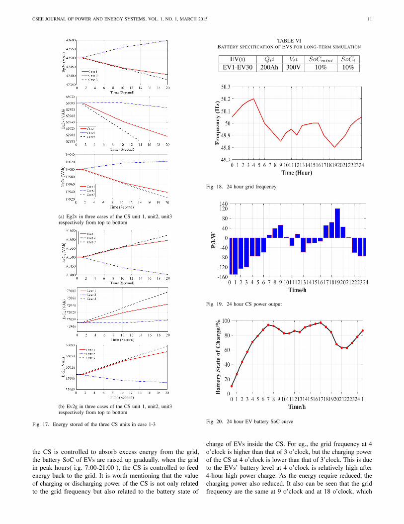
B. Long-term simulation
A long-term simulation has been carried out by consideringa proposed V2G charging station include 6 CS units with 30EVs plugged into the grid at t=0h. Assuming that the 24-hourgrid frequency is as Fig.18 shown. Assuming the SoC and
(a) SV internal frequency, real and reactive power ofthe CS unit 1-3
(b) Battery current of EV1-12
Fig. 16. Simulation results of case 3
the users’ set of all the EVs in the charging station are thesame as table 6 shown. The output power of the proposedV2G charging station in 24 hours are as Fig.19 shown, andthe change of battery SoC in 25 hours is as Fig.20 shown:
From Fig.19 and Fig.20 it can be seen that, when the gridin valley hours( i.g. 0:00-6:00 ), the grid frequency is high,
CSEE JOURNAL OF POWER AND ENERGY SYSTEMS, VOL. 1, NO. 1, MARCH 2015 11
(a) Eg2v in three cases of the CS unit 1, unit2, unit3respectively from top to bottom
(b) Ev2g in three cases of the CS unit 1, unit2, unit3respectively from top to bottom
Fig. 17. Energy stored of the three CS units in case 1-3
the CS is controlled to absorb excess energy from the grid,the battery SoC of EVs are raised up gradually. when the gridin peak hours( i.g. 7:00-21:00 ), the CS is controlled to feedenergy back to the grid. It is worth mentioning that the valueof charging or discharging power of the CS is not only relatedto the grid frequency but also related to the battery state of
TABLE VIBATTERY SPECIFICATION OF EVS FOR LONG-TERM SIMULATION
EV(i) Qti Vti SoCmini SoCiEV1-EV30 200Ah 300V 10% 10%
Fig. 18. 24 hour grid frequency
Fig. 19. 24 hour CS power output
Fig. 20. 24 hour EV battery SoC curve
charge of EVs inside the CS. For eg., the grid frequency at 4o’clock is higher than that of 3 o’clock, but the charging powerof the CS at 4 o’clock is lower than that of 3’clock. This is dueto the EVs’ battery level at 4 o’clock is relatively high after4-hour high power charge. As the energy require reduced, thecharging power also reduced. It also can be seen that the gridfrequency are the same at 9 o’clock and at 18 o’clock, which

CSEE JOURNAL OF POWER AND ENERGY SYSTEMS, VOL. 1, NO. 1, MARCH 2015 12
is lower than the nominal grid frequency. But the battery levelof EVs at 18 o’clock is higher than that of 9 o’clock, thus theoutput power of the former is higher. At 19 o’clock, due toa sharp decrease in grid frequency, the discharging power ofthe CS jumped up rapidly, while at 20 o’clock, due to EVshave discharged a lot of energy to the grid, their battery SoCreduced so that their discharging power reduced as well. Itcan be seen from the long-term simulation that, the proposedV2G charging station is able to regulate its’ input/output poweraccording to the battery status of EVs inside the CS in differentgrid scenarios, it is able to provide frequency regulation serviceto the grid while meeting the energy demand of EV users.
Assuming the base load of the very grid that the CS isplugged in is the red line of fig.21 shown, according tofig.18, the load with the proposed V2G charging station canbe calculated out as the blue line shown. Obviously, Afteremployed the proposed V2G charging station, the peak loadof the grid is cut down significantly, and the valley load isincreased notably. The result of this simulation demonstratesthat the proposed methodology is able to play a role of peakshaving and valley filling for the power network, thus promotingthe efficiency of the electricity grid.
Fig. 21. 24 hour system load with and without the V2G charging station
VI. CONCLUSION
This work proposed a control method for V2G chargingstation based on the synchronverter technology. The CS iscomposed of several CS units connected in parallel and usingsynchronverters as the AC/DC interfaces between each CSunits and the grid. The main features of the proposed methodcan be summarized as follows.
1) A T-S fuzzy controller is designed to decide the refer-ence charging power of the CS unit according to the gridfrequency(which is estimated by the synchronverter itself) andthe charging demand of each individual EV inside the unit;
2) When synchronverter works in P-droop mode(θ ≤ θn,EV 2G > 0), the output power of the CS unit is determined bythe frequency droop control characteristic of the synchronveter,which means a drop of grid frequency would cause a decreaseof reference charging power(or an increase of dischargingpower) of the CS unit in response.
3) An adaptive frequency drooping coefficient mechanism isdesigned to modify the frequency drooping coefficient(also the
slope of the P-f control characteristic) of the synchronverter toadapt the change of the energy capacity of the DC bus;
4) By using the proposed method, a CS can be integratedinto the power grid and behave in the same way as largesynchronous machine do so that the CS equipped with theproposed control strategy and the power grid can be held as awhole based on the well-known synchronous mechanism. Theproposed CS also adds damping and inertia to the power grid,which would help the operation of the grid be more smoother.
Simulation results have verified that the proposed strat-egy can not only effectively perform controlled charg-ing/discharging of each single electric vehicle inside the CS,but providing high-quality frequency and voltage regulationservices for the grid as well.
REFERENCES
[1] Habib S, Kamran M, Rashid U. Impact analysis of vehicle-to-gridtechnology and charging strategies of electric vehicles on distributionnetworks - A review. Journal of Power Sources, 2015, 277, 205-214.
[2] Lund Peter D.; et al. Review of energy system flexibility measures to enablehigh levels of variable renewable electricity. Renewable & SustainableEnergy Reviews, 2015, 45, 785-807.
[3] Karfopoulos E.L.; K. A. Panourgias; and N. D. Hatziargyriou. DistributedCoordination of Electric Vehicles providing V2G Regulation Services.IEEE Transactions on Power Systems, 2016, 31(4), 2834-2846.
[4] Yilmaz,M.; Krein,P. Review of impact of vehicle-to-grid technologies ondistribution systems and utility interface. IEEE Transactions on PowerElectronics, 2013, 28(12), 5673-5689.
[5] K.F. Abdollah; T. Niknam; and M. Fotuhi-Firuzabad. Stochastic Recon-figuration and Optimal Coordination of V2G Plug-in Electric VehiclesConsidering Correlated Wind Power Generation. IEEE Transactions onSustainable Energy , 2015, 6(3), 822-830.
[6] Kisacikoglu Mithat C.; B. Ozpineci; and L. M. Tolbert. EV/PHEVBidirectional Charger Assessment for V2G Reactive Power Operation.IEEETransactions on Power Electronics, 2013,28(12), 5717-5727.
[7] Zhang, Li, et al. Coordinating plug-in electric vehicle charging withelectric grid: Valley filling and target load following.Journal of PowerSources, 2014, 267(4), 584-597.
[8] Chen Niangjun; C. W. Tan; and T. Q. S. Quek. Electric Vehicle Chargingin Smart Grid: Optimality and Valley-Filling Algorithms. IEEE Journalof Selected Topics in Signal Processing, 2014, 8(6),1073-1083.
[9] Sarabi Siyamak; et al. Potential of vehicle-to-grid ancillary servicesconsidering the uncertainties in plug-in electric vehicle availability andservice/localization limitations in distribution grids. Applied Energy, 2016,171, 523-540.
[10] Sortomme,E.; El-Sharkwi,M.A. Optimal scheduling of vehicle-to-gridenergy and ancillary services. IEEE Transactions on Smart Grid,2012,3(1),351-359.
[11] Sekyung,H.; Soohee,H.; Sezaki,K. Development of an optimal vehicle-to-grid aggregator for frequency regulation.IEEE Transactions on SmartGrid, 2010, 1(1),65-72.
[12] Liu Hui, et al. Decentralized Vehicle-to-Grid Control for PrimaryFrequency Regulation Considering Charging Demands. IEEE Transactionson Power Systems, 2013, 28(3), 3480-3489.
[13] Noori Mehdi; et al. Light-duty electric vehicles to improve the integrityof the electricity grid through Vehicle-to-Grid technology: Analysis ofregional net revenue and emissions savings. Applied Energy, 2016, 168,146-158.
[14] Srivastava A.K.; Annabathina B.; Kamalasadan S. The challenges andpolicy options for integrating plug-in hybrid electric vehicle into theelectric grid. The Electricity Journal, 2010, 23(3), 83-91.
[15] Li,Z.; Guo, Q.; Sun,H.; et al. Emission-concerned wind-EV coordinationon the transmission grid side with network constraints: Concept and casestudy. IEEE Transactions on Smart Grid, 2013, 4(3), 1692-1704.
[16] Zhong, Qing Chang. ”Virtual Synchronous Machines: A unified interfacefor grid integration.” 3.4(2016):18-27. IEEE Power Electronics Magazine,2016, 3(4), 18-27.
[17] Zhong, Qing Chang. Power electronics-enabled autonomous powersystems: next generation smart grids. Wiley-IEEE Press, 2017
[18] Zhong QC, Weiss G. Synchronverters: Inverters that mimic synchronousgenerators. Industrial Electronics, IEEE Transactions on. ,2011, 58(4),1259-67.

CSEE JOURNAL OF POWER AND ENERGY SYSTEMS, VOL. 1, NO. 1, MARCH 2015 13
[19] Zhong QC, Nguyen PL, Ma Z, Sheng W. Self-synchronized synchronvert-ers: inverters without a dedicated synchronization unit.Power Electronics,IEEE Transactions on. ,2014, 29(2), 617-30.
[20] Zhong, Qing Chang, and D. Boroyevich. Structural Resemblance BetweenDroop Controllers and Phase-Locked Loops. 4.99(2016):5733-5741. IEEEAccess, 2016, 4(99), 5733-5741.
[21] Takagi T, Sugeno M. Fuzzy identification of systems and its applicationsto modeling and control. Systems, Man and Cybernetics, IEEE Transactionson. , 1985, 1, 116-32.
[22] Thirugnanam Kannan; et al. Modeling and Control of Contactless BasedSmart Charging Station in V2G Scenario. IEEE Transactions on SmartGrid , 2014, 5(1), 337-348.
[23] Hatua Kamalesh; et al. Active Damping of Output LC Filter Resonancefor Vector-Controlled VSI-Fed AC Motor Drives. IEEE Transactions onIndustrial Electronics, 2012, 59(1), 334-342.
[24] Emadi A, Ehasani M, Miller J M. Vehicular Electric Power Systems:Land, Sea, Air and Space Vehicle[M]. New York Marcel Dekker, 2003.
[25] Ehsani A, Yimin Gao, Emadi A, Modern Electric, Hybrid Electric, andFuel Cell Vehicles: Fundamentals, Theory, and Design[M]. Boca Raton,FL, CRC Press, 2005.
Dongqi Liu received the B.S. degree in electronic in-formation engineering from the University of Shang-hai for Science and Technology, Shanghai, China,in 2008, and the Ph.D. degree in control scienceand engineering(awarded the Outstanding GraduatesPrize) from Hunan University, Changsha, Changsha,China, in 2017. He has worked for Shanghai ElectricGroup Co. as an engineer from 2008 to 2010. He hasworked in the Department of Electrical and ComputerEngineering, Illinois Institute of Technology, Chicagoas a visiting researcher from 2015 to 2016 under the
sponsorship of Chinese Scholarship Council.Since 2017, he has been a Lecturer in the School of Electrical and
Information Engineering, Changsha University of Science&Technology. Hisresearch interests include electric vehicles, renewable energy, smart gridintegration etc.
Qing-Chang Zhong received the Ph.D. degree incontrol and power engineering (awarded the BestDoctoral Thesis Prize)from Imperial College London,London, U.K., in 2004 and the Ph.D. degree incontrol theory and engineering from Shanghai JiaoTong University, Shanghai, China, in 2000. He holdsthe Max McGraw Endowed Chair Professor in Energyand Power Engineering at the Dept. of Electricaland Computer Engineering, Illinois Institute of Tech-nology, Chicago, USA, and the Research Professorin Control of Power Systems at the Department of
Automatic Control and Systems Engineering, The University of Sheffield,UK.He is a Distinguished Lecturer of both the IEEE Power Electronics Societyand the IEEE Control Systems Society. He proposed the architecture for thenext-generation smart grids, which adopts the synchronization mechanism ofsynchronous machines to unify the interface and interaction of power systemplayers with the grid and achieve autonomous operation of power systems.His research focuses on power electronics, advanced control theory and theintegration of both, together with applications in renewable energy, smartgrid integration, electric drives and electric vehicles, aircraft power systems,high-speed trains etc. He is a Fellow of IEEE, a Fellow of the Institution ofEngineering and Technology (IET), the Vice-Chair of IFAC TC of Power andEnergy Systems and was a Senior Research Fellow of the Royal Academy ofEngineering/Leverhulme Trust, UK (2009-2010) and the UK Representativeto the European Control Association (2013-2015).
Yaonan Wang received the B.S. degree in com-puter engineering from East China Technology In-stitute(ECTI), Fuzhou, China, in 1981, and the M.S.and Ph.D. degrees in control engineering from HunanUniversity, Changsha, China, in 1990 and 1994,respectively.
Since 1995, he has been a Professor with theCollege of Electrical and Information Engineering,Hunan University. His research interests includehybrid electric vehicle control, intelligent controltheory and its applications.
Dr. Wang was a Senior Humboldt Fellow in Germany from 1998 to 2000and from 2001 to 2004.
Guorong Liu received the B.S. degree and M.S. de-grees in industrial automation from Hunan University,Changsha, China, in 1981 and 1986, respectively, andthe Ph.D. degree in control engineering from Xi’anJiaotong University, Xi’an, China, in 2003.
Since 1997, he has been a Professor with HunanInstitute of Engineering, Xiangtan, China. His re-search interests include intelligent control theory andapplications and modern AC motor control.