csci 320 computer architecture handbook on verilog · pdf filehandbook on verilog hdl by ... a...
TRANSCRIPT

CSCI 320 Handbook on Verilog Page 1
CSCI 320 Computer Architecture Handbook on Verilog HDL
By
Dr. Daniel C. HydeComputer Science Department
Bucknell UniversityLewisburg, PA 17837
Copyright 1995By Daniel C. Hyde
August 25, 1995
Updated August 23, 1997
CSCI 320 Handbook on Verilog Page 2
Table of Contents
1. INTRODUCTION............................................................................4
1.1 What is Verilog?. . . . . . . . . . . . . . . . . . . . . . . . . . . . . . . . . . . . . . . . . . . . . . . . . . . . . . . . . . . . . . . . . . . . . . . . . . . . . 4
1.2 What is VeriWell?. . . . . . . . . . . . . . . . . . . . . . . . . . . . . . . . . . . . . . . . . . . . . . . . . . . . . . . . . . . . . . . . . . . . . . . . . . . 4
1.3 Why Use Verilog HDL?. . . . . . . . . . . . . . . . . . . . . . . . . . . . . . . . . . . . . . . . . . . . . . . . . . . . . . . . . . . . . . . . . . . . 5
2. THE VERILOG LANGUAGE ...........................................................6
2.1 A First Verilog Program . . . . . . . . . . . . . . . . . . . . . . . . . . . . . . . . . . . . . . . . . . . . . . . . . . . . . . . . . . . . . . . . . . . 6
2.2 Lexical Conventions. . . . . . . . . . . . . . . . . . . . . . . . . . . . . . . . . . . . . . . . . . . . . . . . . . . . . . . . . . . . . . . . . . . . . . . . 7
2.3 Program Structure. . . . . . . . . . . . . . . . . . . . . . . . . . . . . . . . . . . . . . . . . . . . . . . . . . . . . . . . . . . . . . . . . . . . . . . . . . . 8
2.4 DATA TYPES ............................................................................1 1
2.4.1 Physical Data Types. . . . . . . . . . . . . . . . . . . . . . . . . . . . . . . . . . . . . . . . . . . . . . . . . . . . . . . . . . . . . . . . . . . . .1 1
2.4.2 Abstract Data Types. . . . . . . . . . . . . . . . . . . . . . . . . . . . . . . . . . . . . . . . . . . . . . . . . . . . . . . . . . . . . . . . . . . . .1 2
2.5 Operators. . . . . . . . . . . . . . . . . . . . . . . . . . . . . . . . . . . . . . . . . . . . . . . . . . . . . . . . . . . . . . . . . . . . . . . . . . . . . . . . . . . . .1 32.5.1 Binary Arithmetic Operators........................................................................... 132.5.2 Unary Arithmetic Operators............................................................................ 132.5.3 Relational Operators........................................................................................ 132.5.4 Logical Operators............................................................................................ 132.5.5 Bitwise Operators............................................................................................ 142.5.6 Unary Reduction Operators............................................................................. 142.5.7 Other Operators................................................................................................ 142.5.8 Operator Precedence......................................................................................... 15
2.6 Control Constructs. . . . . . . . . . . . . . . . . . . . . . . . . . . . . . . . . . . . . . . . . . . . . . . . . . . . . . . . . . . . . . . . . . . . . . . . .1 5
2.6.1 Selection - if and case Statements. . . . . . . . . . . . . . . . . . . . . . . . . . . . . . . . . . . . . . . . . . . . . . . . . . . .1 52.6.2 Repetition - for, while and repeat Statements............................................... 16
2.7 Other Statements. . . . . . . . . . . . . . . . . . . . . . . . . . . . . . . . . . . . . . . . . . . . . . . . . . . . . . . . . . . . . . . . . . . . . . . . . . .1 72.7.1 parameter Statement........................................................................................ 172.7.2 Continuous Assignment.................................................................................. 172.7.3 Blocking and Non-blocking Procedural Assignments.................................... 17
2.8 Tasks and Functions. . . . . . . . . . . . . . . . . . . . . . . . . . . . . . . . . . . . . . . . . . . . . . . . . . . . . . . . . . . . . . . . . . . . . . .1 8
2.9 Timing Control . . . . . . . . . . . . . . . . . . . . . . . . . . . . . . . . . . . . . . . . . . . . . . . . . . . . . . . . . . . . . . . . . . . . . . . . . . . . .2 02.9.1 Delay Control (#)............................................................................................ 212.9.2 Events............................................................................................................... 212.9.3 wait Statement................................................................................................. 222.9.4 fork and join Statements................................................................................. 22
2.10 Traffic Light Example. . . . . . . . . . . . . . . . . . . . . . . . . . . . . . . . . . . . . . . . . . . . . . . . . . . . . . . . . . . . . . . . . . . .2 3

CSCI 320 Handbook on Verilog Page 3
3. USING THE VERIWELL SIMULATOR ..........................................2 5
3.1 Creating the Model File. . . . . . . . . . . . . . . . . . . . . . . . . . . . . . . . . . . . . . . . . . . . . . . . . . . . . . . . . . . . . . . . . . .2 5
3.2 Starting the Simulator. . . . . . . . . . . . . . . . . . . . . . . . . . . . . . . . . . . . . . . . . . . . . . . . . . . . . . . . . . . . . . . . . . . . .2 5
3.3 How to Exit the Simulator? .. . . . . . . . . . . . . . . . . . . . . . . . . . . . . . . . . . . . . . . . . . . . . . . . . . . . . . . . . . . . .2 5
3.4 Simulator Options. . . . . . . . . . . . . . . . . . . . . . . . . . . . . . . . . . . . . . . . . . . . . . . . . . . . . . . . . . . . . . . . . . . . . . . . . .2 5
3.5 Debugging. . . . . . . . . . . . . . . . . . . . . . . . . . . . . . . . . . . . . . . . . . . . . . . . . . . . . . . . . . . . . . . . . . . . . . . . . . . . . . . . . . .2 6
4. SYSTEM TASKS AND FUNCTIONS ............................................2 7
4.1 $cleartrace. . . . . . . . . . . . . . . . . . . . . . . . . . . . . . . . . . . . . . . . . . . . . . . . . . . . . . . . . . . . . . . . . . . . . . . . . . . . . . . . . . . .2 7
4.2 $display. . . . . . . . . . . . . . . . . . . . . . . . . . . . . . . . . . . . . . . . . . . . . . . . . . . . . . . . . . . . . . . . . . . . . . . . . . . . . . . . . . . . . .2 7
4.3 $finish. . . . . . . . . . . . . . . . . . . . . . . . . . . . . . . . . . . . . . . . . . . . . . . . . . . . . . . . . . . . . . . . . . . . . . . . . . . . . . . . . . . . . . . .2 8
4.4 $monitor . . . . . . . . . . . . . . . . . . . . . . . . . . . . . . . . . . . . . . . . . . . . . . . . . . . . . . . . . . . . . . . . . . . . . . . . . . . . . . . . . . . . .2 8
4.5 $scope. . . . . . . . . . . . . . . . . . . . . . . . . . . . . . . . . . . . . . . . . . . . . . . . . . . . . . . . . . . . . . . . . . . . . . . . . . . . . . . . . . . . . . . .2 9
4.6 $settrace. . . . . . . . . . . . . . . . . . . . . . . . . . . . . . . . . . . . . . . . . . . . . . . . . . . . . . . . . . . . . . . . . . . . . . . . . . . . . . . . . . . . . .2 9
4.7 $showscopes. . . . . . . . . . . . . . . . . . . . . . . . . . . . . . . . . . . . . . . . . . . . . . . . . . . . . . . . . . . . . . . . . . . . . . . . . . . . . . . . .2 9
4.8 $showvars. . . . . . . . . . . . . . . . . . . . . . . . . . . . . . . . . . . . . . . . . . . . . . . . . . . . . . . . . . . . . . . . . . . . . . . . . . . . . . . . . . . .2 9
4.9 $stop. . . . . . . . . . . . . . . . . . . . . . . . . . . . . . . . . . . . . . . . . . . . . . . . . . . . . . . . . . . . . . . . . . . . . . . . . . . . . . . . . . . . . . . . . .2 9
4.10 $time. . . . . . . . . . . . . . . . . . . . . . . . . . . . . . . . . . . . . . . . . . . . . . . . . . . . . . . . . . . . . . . . . . . . . . . . . . . . . . . . . . . . . . . .2 9
REFERENCES.................................................................................3 0

CSCI 320 Handbook on Verilog Page 4
1. INTRODUCTION
Verilog HDL is a Hardware Description Language (HDL). A Hardware DescriptionLanguage is a language used to describe a digital system, for example, a computer or a componentof a computer. One may describe a digital system at several levels. For example, an HDL mightdescribe the layout of the wires, resistors and transistors on an Integrated Circuit (IC) chip,i. e., the switch level. Or, it might describe the logical gates and flip flops in a digital system,i. e., the gate level. An even higher level describes the registers and the transfers of vectors ofinformation between registers. This is called the Register Transfer Level (RTL). Verilogsupports all of these levels. However, this handout focuses on only the portions of Verilog whichsupport the RTL level.
1.1 What is Verilog?
Verilog is one of the two major Hardware Description Languages (HDL) used by hardwaredesigners in industry and academia. VHDL is the other one. The industry is currently split onwhich is better. Many feel that Verilog is easier to learn and use than VHDL. As one hardwaredesigner puts it, “I hope the competition uses VHDL.” VHDL was made an IEEE Standard in1987, and Verilog in 1995. Verilog is very C-like and liked by electrical and computer engineersas most learn the C language in college. VHDL is very Ada-like and most engineers have noexperience with Ada.
Verilog was introduced in 1985 by Gateway Design System Corporation, now a part ofCadence Design Systems, Inc.’s Systems Division. Until May, 1990, with the formation of OpenVerilog International (OVI), Verilog HDL was a proprietary language of Cadence. Cadence wasmotivated to open the language to the Public Domain with the expectation that the market forVerilog HDL-related software products would grow more rapidly with broader acceptance of thelanguage. Cadence realized that Verilog HDL users wanted other software and service companiesto embrace the language and develop Verilog-supported design tools.
Verilog HDL allows a hardware designer to describe designs at a high level of abstraction suchas at the architectural or behavioral level as well as the lower implementation levels (i. e. , gate andswitch levels) leading to Very Large Scale Integration (VLSI) Integrated Circuits (IC) layouts andchip fabrication. A primary use of HDLs is the simulation of designs before the designer mustcommit to fabrication. This handout does not cover all of Verilog HDL but focuses on the use ofVerilog HDL at the architectural or behavioral levels. The handout emphasizes design at theRegister Transfer Level (RTL).
1.2 What is VeriWell?
VeriWell is a comprehensive implementation of Verilog HDL originally developed byWellspring Solutions, Inc. VeriWell supports the Verilog language as specified by the OVIlanguage Reference Manual. VeriWell was first introduced in December, 1992, and was written tobe compatible with both the OVI standard and with Cadence’s Verilog-XL.
VeriWell is now distributed and sold by SynaptiCAD Inc. For Windows 95/NT, Windows 3.1,Macintosh, SunOS and Linux platforms, SynaptiCAD Inc. offers FREE versions of their VeriWellproduct available from http://www.syncad.com/ver_down.htm. The free versions are the same asthe industrial versions except they are restricted to a maximum of 1000 lines of HDL code.
CSCI 320 Handbook on Verilog Page 5
1.3 Why Use Verilog HDL?
Digital systems are highly complex. At their most detailed level, they may consists of millionsof elements, i. e., transistors or logic gates. Therefore, for large digital systems, gate-level designis dead. For many decades, logic schematics served as the lingua franca of logic design, but notany more. Today, hardware complexity has grown to such a degree that a schematic with logicgates is almost useless as it shows only a web of connectivity and not the functionality of design.Since the 1970s, Computer engineers and electrical engineers have moved toward hardwaredescription languages (HDLs). The most prominent modern HDLs in industry are Verilog andVHDL. Verilog is the top HDL used by over 10,000 designers at such hardware vendors as SunMicrosystems, Apple Computer and Motorola. Industrial designers like Verilog. It works.
The Verilog language provides the digital designer with a means of describing a digital system ata wide range of levels of abstraction, and, at the same time, provides access to computer-aideddesign tools to aid in the design process at these levels.
Verilog allows hardware designers to express their design with behavioral constructs,deterring the details of implementation to a later stage of design in the design. An abstractrepresentation helps the designer explore architectural alternatives through simulations and todetect design bottlenecks before detailed design begins.
Though the behavioral level of Verilog is a high level description of a digital system, it is still aprecise notation. Computer-aided-design tools, i. e., programs, exist which will “compile”programs in the Verilog notation to the level of circuits consisting of logic gates and flip flops.One could then go to the lab and wire up the logical circuits and have a functioning system. And,other tools can “compile” programs in Verilog notation to a description of the integrated circuitmasks for very large scale integration (VLSI). Therefore, with the proper automated tools,one can create a VLSI description of a design in Verilog and send the VLSI description viaelectronic mail to a silicon foundry in California and receive the integrated chip in a few weeksby way of snail mail. Verilog also allows the designer to specific designs at the logical gate levelusing gate constructs and the transistor level using switch constructs.
Our goal in the course is not to create VLSI chips but to use Verilog to precisely describe thefunctionality of any digital system, for example, a computer. However, a VLSI chip designed byway of Verilog’s behavioral constructs will be rather slow and be wasteful of chip area. Thelower levels in Verilog allow engineers to optimize the logical circuits and VLSI layouts tomaximize speed and minimize area of the VLSI chip.

CSCI 320 Handbook on Verilog Page 6
2. The Verilog Language
There is no attempt in this handout to describe the complete Verilog language. It describes onlythe portions of the language needed to allow students to explore the architectural aspects ofcomputers. In fact, this handout covers only a small fraction of the language. For the completedescription of the Verilog HDL, consult the references at the end of the handout.
We begin our study of the Verilog language by looking at a simple Verilog program. Looking atthe assignment statements, we notice that the language is very C-like. Comments have a C++flavor, i e., they are shown by “//” to the end of the line. The Verilog language describes a digitalsystem as a set of modules, but here we have only a single module called “simple”.
2.1 A First Verilog Program
/ /By Dan Hyde; August 9, 1995//A first digital model in Verilog
module simple;// Simple Register Transfer Level (RTL) example to demo Verilog.// The register A is incremented by one. Then first four bits of B is// set to "not" of the last four bits of A. C is the "and" reduction// of the last two bits of A.//declare registers and flip-flopsreg [0:7] A, B;reg C;
// The two "initial"s and "always" will run concurrentlyinitial begin: stop_at // Will stop the execution after 20 simulation units. #20; $stop;end
// These statements done at simulation time 0 (since no #k)initial begin: Init // Initialize the register A. The other registers have values of "x" A = 0;
// Display a header $display("Time A B C");
// Prints the values anytime a value of A, B or C changes $monitor(" %0d %b %b %b", $time, A, B, C);end
//main_process will loop until simulation is overalways begin: main_process
// #1 means do after one unit of simulation time #1 A = A + 1; #1 B[0:3] = ~A[4:7]; // ~ is bitwise "not" operator #1 C = &A[6:7]; // bitwise "and" reduction of last two bits of A
endendmodule
CSCI 320 Handbook on Verilog Page 7
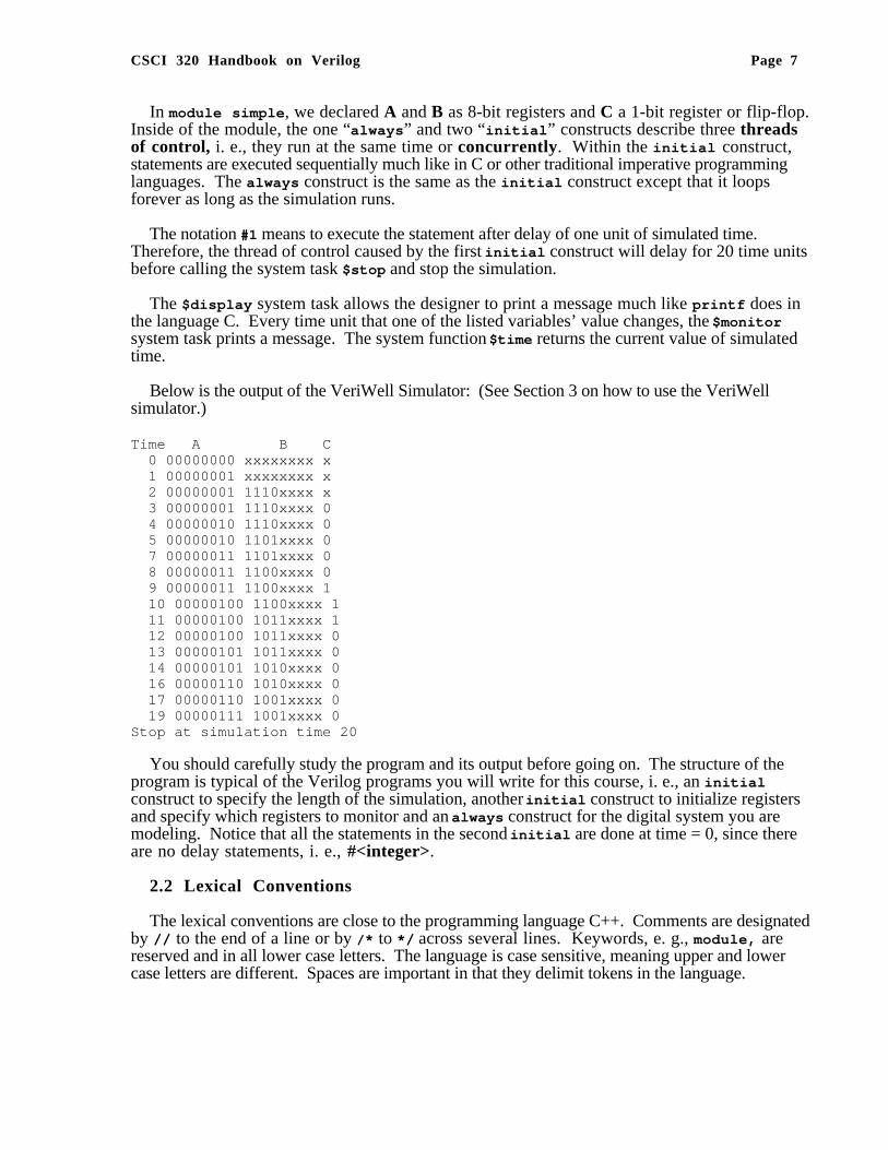
In module simple , we declared A and B as 8-bit registers and C a 1-bit register or flip-flop.Inside of the module, the one “always ” and two “initial ” constructs describe three threadsof control, i. e., they run at the same time or concurrently. Within the initial construct,statements are executed sequentially much like in C or other traditional imperative programminglanguages. The always construct is the same as the initial construct except that it loopsforever as long as the simulation runs.
The notation #1 means to execute the statement after delay of one unit of simulated time.Therefore, the thread of control caused by the first initial construct will delay for 20 time unitsbefore calling the system task $stop and stop the simulation.
The $display system task allows the designer to print a message much like printf does inthe language C. Every time unit that one of the listed variables’ value changes, the $monitorsystem task prints a message. The system function $time returns the current value of simulatedtime.
Below is the output of the VeriWell Simulator: (See Section 3 on how to use the VeriWellsimulator.)
Time A B C 0 00000000 xxxxxxxx x 1 00000001 xxxxxxxx x 2 00000001 1110xxxx x 3 00000001 1110xxxx 0 4 00000010 1110xxxx 0 5 00000010 1101xxxx 0 7 00000011 1101xxxx 0 8 00000011 1100xxxx 0 9 00000011 1100xxxx 1 10 00000100 1100xxxx 1 11 00000100 1011xxxx 1 12 00000100 1011xxxx 0 13 00000101 1011xxxx 0 14 00000101 1010xxxx 0 16 00000110 1010xxxx 0 17 00000110 1001xxxx 0 19 00000111 1001xxxx 0Stop at simulation time 20
You should carefully study the program and its output before going on. The structure of theprogram is typical of the Verilog programs you will write for this course, i. e., an initialconstruct to specify the length of the simulation, another initial construct to initialize registersand specify which registers to monitor and an always construct for the digital system you aremodeling. Notice that all the statements in the second initial are done at time = 0, since thereare no delay statements, i. e., #<integer>.
2.2 Lexical Conventions
The lexical conventions are close to the programming language C++. Comments are designatedby // to the end of a line or by / * to */ across several lines. Keywords, e. g., module, arereserved and in all lower case letters. The language is case sensitive, meaning upper and lowercase letters are different. Spaces are important in that they delimit tokens in the language.

CSCI 320 Handbook on Verilog Page 8
Numbers are specified in the traditional form of a series of digits with or without a sign but alsoin the following form:
<size><base format><number>
where <size> contains decimal digits that specify the size of the constant in the number of bits.The <size> is optional. The <base format> is the single character ' followed by one of thefollowing characters b, d, o and h, which stand for binary, decimal, octal and hex, respectively.The <number> part contains digits which are legal for the <base format>. Some examples:
549 // decimal number'h 8FF // hex number'o765 // octal number4'b11 // 4-bit binary number 00113'b10x // 3-bit binary number with least significant bit unknown5'd3 // 5-bit decimal number-4'b11 // 4-bit two's complement of 0011 or 1101
The <number> part may not contain a sign. Any sign must go on the front.
A string is a sequence of characters enclosed in double quotes.
"this is a string"
Operators are one, two or three characters and are used in expressions. See Section 2.5 for theoperators.
An identifier is specified by a letter or underscore followed by zero or more letters, digits, dollarsigns and underscores. Identifiers can be up to 1024 characters.
2.3 Program Structure
The Verilog language describes a digital system as a set of modules. Each of these modules hasan interface to other modules to describe how they are interconnected. Usually we place onemodule per file but that is not a requirement. The modules may run concurrently, but usually wehave one top level module which specifies a closed system containing both test data and hardwaremodels. The top level module invokes instances of other modules.
Modules can represent pieces of hardware ranging from simple gates to complete systems, e. g.,a microprocessor. Modules can either be specified behaviorally or structurally (or a combination ofthe two). A behavioral specification defines the behavior of a digital system (module) usingtraditional programming language constructs, e. g., ifs, assignment statements. A structuralspecification expresses the behavior of a digital system (module) as a hierarchicalinterconnection of sub modules. At the bottom of the hierarchy the components must be primitivesor specified behaviorally. Verilog primitives include gates, e. g., nand, as well as pass transistors(switches).
The structure of a module is the following:
module <module name> (<port list>);<declares><module items>endmodule

CSCI 320 Handbook on Verilog Page 9
The <module name> is an identifier that uniquely names the module. The <port list> is a listof input, inout and output ports which are used to connect to other modules. The <declares>section specifies data objects as registers, memories and wires as wells as procedural constructssuch as functions and tasks.
The <module items> may be initial constructs, always constructs, continuousassignments or instances of modules.
The semantics of the module construct in Verilog is very different from subroutines,procedures and functions in other languages. A module is never called! A module is instantiated atthe start of the program and stays around for the life of the program. A Verilog moduleinstantiation is used to model a hardware circuit where we assume no one unsolders or changes thewiring. Each time a module is instantiated, we give its instantiation a name. For example,NAND1 and NAND2 are the names of instantiations of our NAND gate in the below example.
Here is a behavior specification of a module NAND. The output out is the not of the and ofthe inputs in1 and in2.
// Behavioral Model of a Nand gate// By Dan Hyde, August 9, 1995module NAND(in1, in2, out);
input in1, in2; output out; // continuous assign statement assign out = ~(in1 & in2);endmodule
The ports in1, in2 and out are labels on wires. The continuous assignment assigncontinuously watches for changes to variables in its right hand side and whenever that happens theright hand side is re-evaluated and the result immediately propagated to the left hand side (out).The continuous assignment statement is used to model combinational circuits where theoutputs change when one wiggles the input.
Here is a structural specification of a module AND obtained by connecting the output of oneNAND to both inputs of another one.
module AND(in1, in2, out);// Structural model of AND gate from two NANDS input in1, in2; output out; wire w1; // two instantiations of the module NAND NAND NAND1(in1, in2, w1); NAND NAND2(w1, w1, out);endmodule
This module has two instances of the NAND module called NAND1 and NAND2 connectedtogether by an internal wire w1.
The general form to invoke an instance of a module is :
<module name> <parameter list> <instance name> (<port list>);

CSCI 320 Handbook on Verilog Page 10
where <parameter list> are values of parameters passed to the instance. An example parameterpassed would be the delay for a gate.
The following module is a high level module which sets some test data and sets up themonitoring of variables.
module test_AND;// High level module to test the two other modules reg a, b; wire out1, out2;
initial begin // Test data a = 0; b = 0; #1 a = 1; #1 b = 1; #1 a = 0; end
initial begin // Set up monitoring $monitor("Time=%0d a=%b b=%b out1=%b out2=%b", $time, a, b, out1, out2); end // Instances of modules AND and NAND AND gate1(a, b, out2); NAND gate2(a, b, out1);
endmodule
Notice that we need to hold the values a and b over time. Therefore, we had to use 1-bitregisters. reg variables store the last value that was procedurally assigned to them (just likevariables in traditional imperative programming languages). wires have no storage capacity.They can be continuously driven, e. g., with a continuous assign statement or by the output of amodule, or if input wires are left unconnected, they get the special value of x for unknown.
Continuous assignments use the keyword assign whereas procedural assignments have theform <reg variable> = <expression> where the <reg variable> must be a register ormemory. Procedural assignment may only appear in initial and always constructs.
The statements in the block of the first initial construct will be executed sequentially, someof which are delayed by #1, i. e., one unit of simulated time. The always construct behaves thesame as the initial construct except that it loops forever (until the simulation stops). Theinitial and always constructs are used to model sequential logic (i. e., finite stateautomata).
Verilog makes an important distinction between procedural assignment and the continuousassignment assign . Procedural assignment changes the state of a register, i. e., sequentiallogic, whereas the continuous statement is used to model combinational logic. Continuousassignments drive wire variables and are evaluated and updated whenever an input operandchanges value. It is important to understand and remember the difference.
We place all three modules in a file and run the simulator to produce the following output.

CSCI 320 Handbook on Verilog Page 11
Time=0 a=0 b=0 out1=1 out2=0Time=1 a=1 b=0 out1=1 out2=0Time=2 a=1 b=1 out1=0 out2=1Time=3 a=0 b=1 out1=1 out2=0
Since the simulator ran out of events, I didn't need to explicitly stop the simulation.
2.4 Data Types
2.4.1 Physical Data Types
Since the purpose of Verilog HDL is to model digital hardware, the primary data types are formodeling registers (reg ) and wires (wire ). The reg variables store the last value that wasprocedurally assigned to them whereas the wire variables represent physical connections betweenstructural entities such as gates. A wire does not store a value. A wire variable is really only alabel on a wire. (Note that the wire data type is only one of several net data types in VerilogHDL which include “wired and (wand), “wired or (wor ) and “ristate bus (tri ). This handout isrestricted to only the wire data type.)
The reg and wire data objects may have the following possible values:
0 logical zero or false1 logical one or truex unknown logical valuez high impedance of tristate gate
The reg variables are initialized to x at the start of the simulation. Any wire variable notconnected to something has the x value.
You may specify the size of a register or wire in the declaration For example, the declarations
reg [0:7] A, B;wire [0:3] Dataout;reg [7:0] C;
specify registers A and B to be 8-bit wide with the most significant bit the zeroth bit, whereas themost significant bit of register C is bit seven. The wire Dataout is 4 bits wide.
The bits in a register or wire can be referenced by the notation [<start-bit>:<end-bit>] .For example, in the second procedural assignment statement
initial begin: int1A = 8'b01011010;B = {A[0:3] | A[4:7], 4'b0000};
end
B is set to the first four bits of A bitwise or-ed with the last four bits of A and then concatenatedwith 0000. B now holds a value of 11110000. The {} brackets means the bits of the two ormore arguments separated by commas are concatenated together.

CSCI 320 Handbook on Verilog Page 12
An argument may be replicated by specifying a repetition number of the form:
{repetition_number{exp1, exp2, ... , expn}}
Here are some examples:
C = {2{4’b1011}}; //C assigned the bit vector 8’b10111011C = {{4{A[4]}}, AA[4:7]}; // first 4 bits are sign extension
The range referencing in an expression must have constant expression indices . However, asingle bit may be referenced by a variable. For example:
reg [0:7] A, B;B = 3;A[0: B] = 3'b111; // ILLEGAL - indices MUST be constant!!A[B] = 1'b1; // A single bit reference is LEGAL
Why such a strict requirement of constant indices in register references? Since we are describinghardware, we want only expressions which are realizable.
Memories are specified as vectors of registers. For example, Mem is 1K words each 32-bits.
reg [31:0] Mem [0:1023];
The notation Mem[0] references the zeroth word of memory. The array index for memory(register vector) may be a register. Notice that one can not reference a memory at the bit-level inVerilog HDL. If you want a specific range of bits in a word of memory, you must first transfer thedata in the word to a temporary register.
2.4.2 Abstract Data Types
In addition to modeling hardware, there are other uses for variables in a hardware model. Forexample, the designer might want to use an integer variable to count the number of times anevent occurs. For the convenience of the designer, Verilog HDL has several data types which donot have a corresponding hardware realization. These data types include integer , real andtime . The data types integer and real behave pretty much as in other languages, e. g., C.Be warned that a reg variable is unsigned and that an integer variable is a signed 32-bitinteger. This has important consequences when you subtract.
time variables hold 64-bit quantities and are used in conjunction with the $time systemfunction. Arrays of integer and time variables (but not reals) are allowed. Multipledimensional arrays are not allowed in Verilog HDL. Some examples:
integer Count; // simple signed 32-bit integerinteger K[1:64]; // an array of 64 integerstime Start, Stop; // Two 64-bit time variables
2.5 Operators
2.5.1 Binary Arithmetic Operators
Binary arithmetic operators operate on two operands. Register and net, i. e., wire, operands aretreated as unsigned. However, real and integer operands may be signed. If any bit of an operandis unknown ('x') then the result is unknown.

CSCI 320 Handbook on Verilog Page 13
Operator Name Comments+ Addition- Subtraction* Multiplication/ Division Divide by zero produces an x, i. e., unknown.% Modulus
2.5.2 Unary Arithmetic Operators
Operator Name Comments- Unary Minus Changes sign of its operand.
2.5.3 Relational Operators
Relational operators compare two operands and return a logical value, i. e., TRUE(1) orFALSE(0). If any bit is unknown, the relation is ambiguous and the result is unknown.
Operator Name Comments> Greater than>= Greater than or equal< Less than<= Less than or equal== Logical equality!= Logical inequality
2.5.4 Logical Operators
Logical operators operate on logical operands and return a logical value, i. e., TRUE(1) orFALSE(0). Used typically in if and while statements. Do not confuse logical operators with thebitwise Boolean operators. For example , ! is a logical NOT and ~ is a bitwise NOT. The firstnegates, e. g., !(5 == 6) is TRUE. The second complements the bits, e. g., ~{1,0,1,1} is 0100.
Operator Name Comments! Logical negation&& Logical AND|| Logical OR
2.5.5 Bitwise Operators
Bitwise operators operate on the bits of the operand or operands. For example, the result of A& B is the AND of each corresponding bit of A with B. Operating on an unknown (x) bit resultsin the expected value. For example, the AND of an x with a FALSE is an x. The OR of an x witha TRUE is a TRUE.
Operator Name Comments~ Bitwise negation& Bitwise AND| Bitwise OR^ Bitwise XOR~& Bitwise NAND~| Bitwise NOR~^ or ^~ Equivalence Bitwise NOT XOR
2.5.6 Unary Reduction Operators

CSCI 320 Handbook on Verilog Page 14
Unary reduction operators produce a single bit result from applying the operator to all of the bitsof the operand. For example, &A will AND all the bits of A.
Operator Name Comments& AND reduction| OR reduction^ XOR reduction~& NAND reduction~| NOR reduction~^ XNOR reduction
2.5.7 Other OperatorsThe conditional operator operates much like in the language C.
Operator Name Comments=== Case equality The bitwise comparison includes comparison of x and z
values. All bits must match for equality. Returns TRUE or FALSE.!== Case inequality The bitwise comparison includes comparison of x and z
values. Any bit difference produces inequality. Returns TRUE or FALSE.{ , } Concatenation Joins bits together with 2 or more comma-separated
expressions, e, g. {A[0], B[1:7]} concatenates the zerothbit of A to bits 1 to 7 of B.
<< Shift left Vacated bit positions are filled with zeros, e.. g.,A = A << 2; //shifts A two bits to left with zero fill.
>> Shift right Vacated bit positions are filled with zeros.?: Conditional Assigns one of two values depending on the conditional
expression. E. g., A = C>D ? B+3 : B-2 means if C greater than D, the value of A is B+3 otherwise B-2.
2.5.8 Operator Precedence
The precedence of operators is shown below. The top of the table is the highest precedence andthe bottom is the lowest. Operators on the same line have the same precedence and associate left toright in an expression. Parentheses can be used to change the precedence or clarify the situation.We strongly urge you to use parentheses to improve readability.
unary operators: ! & ~& | ~| ^ ~^ + - (highest precedence)* / %
+ -<< >>
< <= > >+== != === ~==
& ~& ^ ~^| ~|
&&||?:

CSCI 320 Handbook on Verilog Page 15
2.6 Control Constructs
Verilog HDL has a rich collection of control statements which can used in the proceduralsections of code, i. e., within an initial or always block. Most of them will be familiar to theprogrammer of traditional programming languages like C. The main difference is instead of C's{ } brackets, Verilog HDL uses begin and end . In Verilog, the { } brackets are used forconcatenation of bit strings. Since most users are familiar with C, the following subsectionstypically show only an example of each construct.
2.6.1 Selection - i f and case Statements
The if statement is easy to use.
if (A == 4) begin B = 2; end else begin B = 4; end
Unlike the case statement in C, the first <value> that matches the value of the<expression> is selected and the associated statement is executed then control is transferred toafter the endcase , i. e., no break statements are needed as in C.
case ( <expression>) <value1>: <statement> <value2>: <statement> default: <statement> endcase
The following example checks a 1-bit signal for its value.
case (sig) 1'bz: $display("Signal is floating"); 1'bx: $display("Signal is unknown"); default: $display("Signal is %b", sig); endcase
2.6.2 Repetition - for , while and repeat Statements
The for statement is very close to C's for statement except that the ++ and -- operators do notexist in Verilog. Therefore, we need to use i = i + 1.
for(i = 0; i < 10; i = i + 1) begin $display("i= %0d", i); end

CSCI 320 Handbook on Verilog Page 16
The while statement acts in the normal fashion.
i = 0; while(i < 10) begin $display("i= %0d", i); i = i + 1; end
The repeat statement repeats the following block a fixed number of times, in this example,five times.
repeat (5) begin $display("i= %0d", i); i = i + 1; end
2.7 Other Statements
2.7.1 parameter Statement
The parameter statement allows the designer to give a constant a name. Typical uses are tospecify width of registers and delays. For example, the following allows the designer toparameterized the declarations of a model.
parameter byte_size = 8;
reg [byte_size - 1:0] A, B;
2.7.2 Continuous Assignment
Continuous assignments drive wire variables and are evaluated and updated whenever an inputoperand changes value. The following ands the values on the wires in1 and in2 and drives thewire out. The keyword assign is used to distinguish the continuous assignment from theprocedural assignment. See page 7 for more discussion on continuous assignment.
assign out = ~(in1 & in2);
2.7.3 Blocking and Non-blocking Procedural Assignments
The Verilog language has two forms of the procedural assignment statement: blocking and non-blocking. The two are distinguished by the = and <= assignment operators. The blockingassignment statement (= operator) acts much like in traditional programming languages. Thewhole statement is done before control passes on to the next statement. The non-blocking (<=operator) evaluates all the right-hand sides for the current time unit and assigns the left-hand sidesat the end of the time unit. For example, the following Verilog program
// testing blocking and non-blocking assignmentmodule blocking;reg [0:7] A, B;initial begin: init1 A = 3;

CSCI 320 Handbook on Verilog Page 17
#1 A = A + 1; // blocking procedural assignment B = A + 1; $display("Blocking: A= %b B= %b", A, B );
A = 3; #1 A <= A + 1; // non-blocking procedural assignment B <= A + 1;
#1 $display("Non-blocking: A= %b B= %b", A, B );end
endmodule
produces the following output:
Blocking: A= 00000100 B= 00000101Non-blocking: A= 00000100 B= 00000100
The effect is for all the non-blocking assignments to use the old values of the variables at thebeginning of the current time unit and to assign the registers new values at the end of the currenttime unit. This reflects how register transfers occur in some hardware systems.
2.8 Tasks and Functions
Tasks are like procedures in other programming languages, e. g., tasks may have zero or morearguments and do not return a value. Functions act like function subprograms in other languages. Except:
1. A Verilog function must execute in one simulation time unit. That is, no time controllingstatements, i. e., no delay control (#), no event control (@) or wait statements, allowed. A taskmay contain time controlled statements.
2. A Verilog function can not invoke (call, enable) a task; whereas a task can call other tasks andfunctions.
The definition of a task is the following:
task <task name>; // Notice: no list of parameters or ()s<argument ports><declarations><statements>
endtask
An invocation of a task is of the following form:
<name of task> (<port list>);
where <port list> is a list of expressions which correspond by position to the <argumentports> of the definition. Port arguments in the definition may be input , inout or output .Since the <argument ports> in the task definition look like declarations, the programmer mustbe careful in adding declares at the beginning of a task.
CSCI 320 Handbook on Verilog Page 18
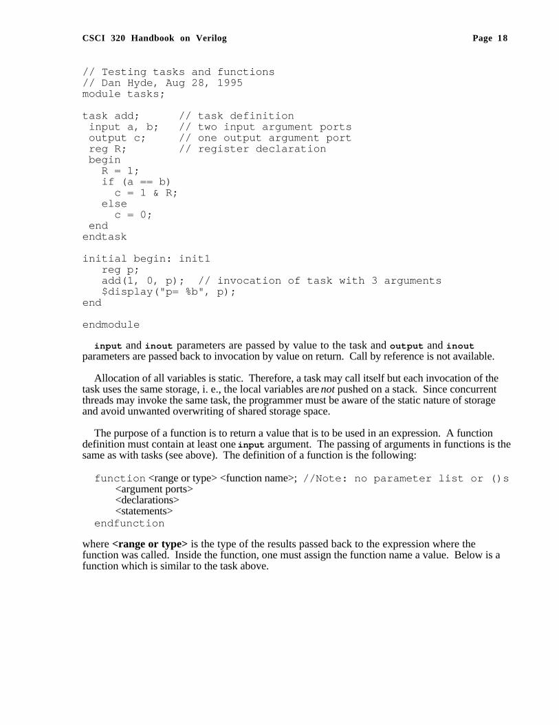
// Testing tasks and functions// Dan Hyde, Aug 28, 1995module tasks;
task add; // task definition input a, b; // two input argument ports output c; // one output argument port reg R; // register declaration begin R = 1; if (a == b) c = 1 & R; else c = 0; endendtask
initial begin: init1 reg p; add(1, 0, p); // invocation of task with 3 arguments $display("p= %b", p);end
endmodule
input and inout parameters are passed by value to the task and output and inoutparameters are passed back to invocation by value on return. Call by reference is not available.
Allocation of all variables is static. Therefore, a task may call itself but each invocation of thetask uses the same storage, i. e., the local variables are not pushed on a stack. Since concurrentthreads may invoke the same task, the programmer must be aware of the static nature of storageand avoid unwanted overwriting of shared storage space.
The purpose of a function is to return a value that is to be used in an expression. A functiondefinition must contain at least one input argument. The passing of arguments in functions is thesame as with tasks (see above). The definition of a function is the following:
function <range or type> <function name>; //Note: no parameter list or ()s<argument ports><declarations><statements>
endfunction
where <range or type> is the type of the results passed back to the expression where thefunction was called. Inside the function, one must assign the function name a value. Below is afunction which is similar to the task above.
CSCI 320 Handbook on Verilog Page 19
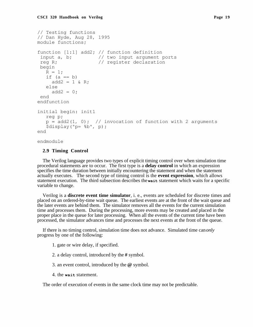
// Testing functions// Dan Hyde, Aug 28, 1995module functions;
function [1:1] add2; // function definition input a, b; // two input argument ports reg R; // register declaration begin R = 1; if (a == b) add2 = 1 & R; else add2 = 0; endendfunction
initial begin: init1 reg p; p = add2(1, 0); // invocation of function with 2 arguments $display("p= %b", p);end
endmodule
2.9 Timing Control
The Verilog language provides two types of explicit timing control over when simulation timeprocedural statements are to occur. The first type is a delay control in which an expressionspecifies the time duration between initially encountering the statement and when the statementactually executes. The second type of timing control is the event expression, which allowsstatement execution. The third subsection describes the wait statement which waits for a specificvariable to change.
Verilog is a discrete event time simulator, i. e., events are scheduled for discrete times andplaced on an ordered-by-time wait queue. The earliest events are at the front of the wait queue andthe later events are behind them. The simulator removes all the events for the current simulationtime and processes them. During the processing, more events may be created and placed in theproper place in the queue for later processing. When all the events of the current time have beenprocessed, the simulator advances time and processes the next events at the front of the queue.
If there is no timing control, simulation time does not advance. Simulated time can onlyprogress by one of the following:
1. gate or wire delay, if specified.
2. a delay control, introduced by the # symbol.
3. an event control, introduced by the @ symbol.
4. the wait statement.
The order of execution of events in the same clock time may not be predictable.

CSCI 320 Handbook on Verilog Page 20
2.9.1 Delay Control (#)
A delay control expression specifies the time duration between initially encountering thestatement and when the statement actually executes. For example:
#10 A = A + 1;
specifies to delay 10 time units before executing the procedural assignment statement. The # maybe followed by an expression with variables.
2.9.2 Events
The execution of a procedural statement can be triggered with a value change on a wire orregister, or the occurrence of a named event. Some examples:
@r begin // controlled by any value change inA = B&C; // the register r
end
@(posedge clock2) A = B&C; // controlled by positive edge of clock2
@(negedge clock3) A = B&C; // controlled by negative edge of clock3
forever @(negedge clock) // controlled by negative edge begin
A = B&C;end
In the forms using posedge and negedge, they must be followed by a 1-bit expression,typically a clock. A negedge is detected on the transition from 1 to 0 (or unknown). Aposedge is detected on the transition from 0 to 1 (or unknown).
Verilog also provides features to name an event and then to trigger the occurrence of that event.We must first declare the event:
event event6;
To trigger the event, we use the -> symbol :
-> event6;
To control a block of code, we use the @ symbol as shown:
@(event6) begin<some procedural code>
end
We assume that the event occurs in one thread of control, i. e., concurrently, and the controlledcode is in another thread. Several events may to or-ed inside the parentheses.

CSCI 320 Handbook on Verilog Page 21
2.9.3 wait Statement
The wait statement allows a procedural statement or a block to be delayed until a conditionbecomes true.
wait (A == 3)begin A = B&C;end
The difference between the behavior of a wait statement and an event is that the waitstatement is level sensitive whereas @(posedge clock); is triggered by a signaltransition or is edge sensitive.
2.9.4 fork and join Statements
By using the fork and join construct, Verilog allows more than one thread of control inside aninitial or always construct.
For example, to have three threads of control, you fork the thread into three and merge the threeinto one with a join as shown:
fork: three // split thread into three; one for each begin-endbegin
// code for thread 1endbegin
// code for thread 2endbegin
// code for thread 3end
join // merge the threads to one
Each statement between the fork and join , in this case, the three begin-end blocks, is executedconcurrently. After all the threads complete, the next statement after the join is executed.
You must be careful that there is no interference between the different threads. For example,you can’t change a register in two different threads during the same clock period.

CSCI 320 Handbook on Verilog Page 22
2.10 Traffic Light Example
To demonstrate tasks as well as events, we will show a hardware model of a traffic light.
// Digital model of a traffic light// By Dan Hyde August 10, 1995module traffic;parameter on = 1, off = 0, red_tics = 35, amber_tics = 3, green_tics = 20;reg clock, red, amber, green;
// will stop the simulation after 1000 time unitsinitial begin: stop_at #1000; $stop;end
// initialize the lights and set up monitoring of registersinitial begin: Init red = off; amber = off; green = off; $display(" Time green amber red"); $monitor("%3d %b %b %b", $time, green, amber, red);end
// task to wait for 'tics' positive edge clocks// before turning light offtask light; output color; input [31:0] tics; begin repeat(tics) // wait to detect tics positive edges on clock @(posedge clock); color = off; endendtask
// waveform for clock period of 2 time unitsalways begin: clock_wave #1 clock = 0; #1 clock = 1;end
always begin: main_process red = on; light(red, red_tics); // call task to wait green = on; light(green, green_tics); amber = on; light(amber, amber_tics);end
endmodule
The output of the traffic light simulator is the following:

CSCI 320 Handbook on Verilog Page 23
Time green amber red 0 0 0 1 70 1 0 0 110 0 1 0 116 0 0 1 186 1 0 0 226 0 1 0 232 0 0 1 302 1 0 0 342 0 1 0 348 0 0 1 418 1 0 0 458 0 1 0 464 0 0 1 534 1 0 0 574 0 1 0 580 0 0 1 650 1 0 0 690 0 1 0 696 0 0 1 766 1 0 0 806 0 1 0 812 0 0 1 882 1 0 0 922 0 1 0 928 0 0 1 998 1 0 0Stop at simulation time 1000

CSCI 320 Handbook on Verilog Page 24
3. Using the VeriWell Simulator
3.1 Creating the Model File
Enter the Verilog code using your favorite editor. We recommend that you use “.v” as theextension on the source file.
3.2 Starting the Simulator
VeriWell is run from the UNIX shell window. Type "veriwell" followed by the names of thefiles containing the models and the options. The options can appear in any order and anywhere onthe command line. For example:
host-name% veriwell cpu.v bus.v top.v -s
This will load each of the files into memory, compile them, and enter interactive mode. Removingthe "-s" option would cause the simulation to begin immediately. Options are processed in theorder that they appear on the command line. Files are processed in the order that they appear afterthe options are processed.
3.3 How to Exit the Simulator?
To exit the simulator, you can type $finish; or press Control-d .
To stop the simulation, you press Control-c. Executing a $stop; system task in the codewill also stop the simulation.
3.4 Simulator Options
Commonly used options typed on the command line are shown below. One should consult theVeriWell User’s Guide for the others.
-i <inputfilename>Specifies a file that contains interactive commands to be executed as soon as interactive
command mode is entered. This option should be used with the "-s" option. This can be used toinitialize variables and set time limits on the simulation.
- sCauses interactive mode to be entered before the simulation begins.
- tCauses all statements to be traced. Trace mode may be disabled with the $cleartrace
system task.
CSCI 320 Handbook on Verilog Page 25
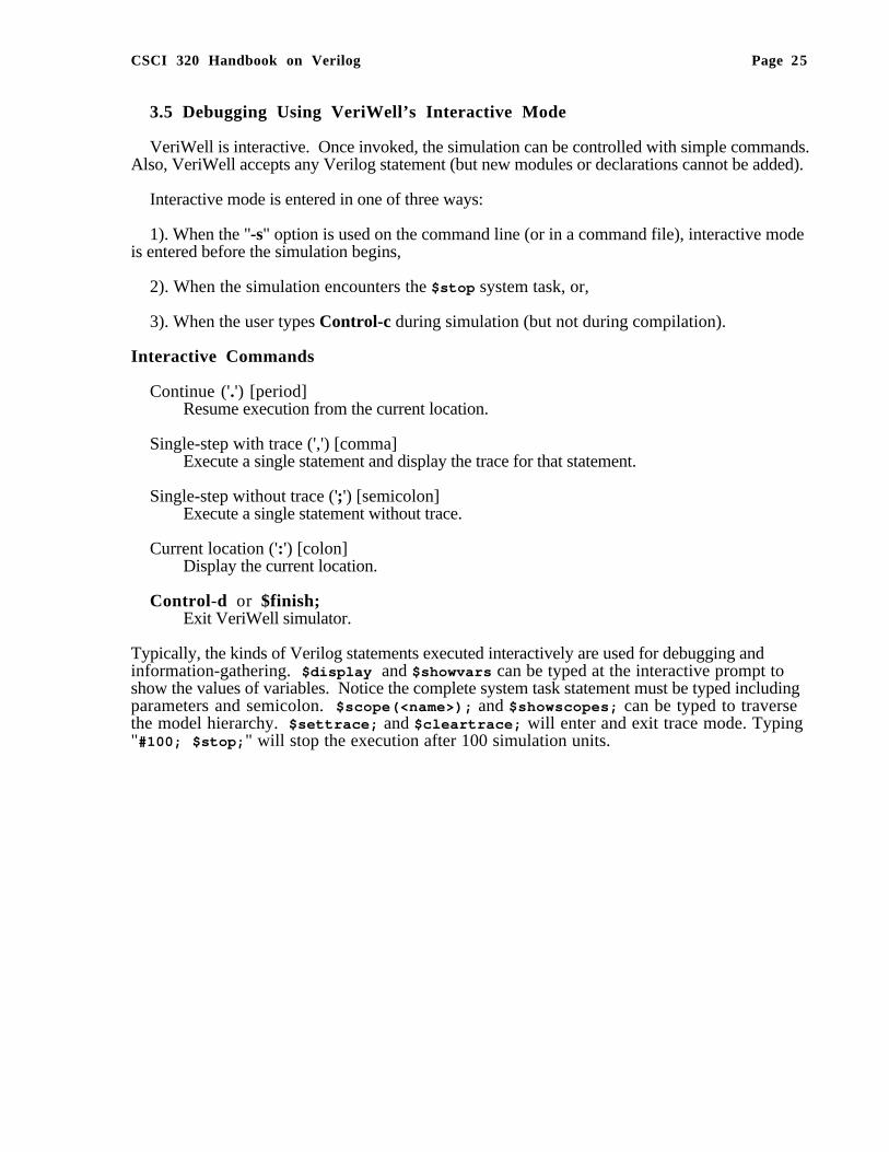
3.5 Debugging Using VeriWell’s Interactive Mode
VeriWell is interactive. Once invoked, the simulation can be controlled with simple commands.Also, VeriWell accepts any Verilog statement (but new modules or declarations cannot be added).
Interactive mode is entered in one of three ways:
1). When the "-s" option is used on the command line (or in a command file), interactive modeis entered before the simulation begins,
2). When the simulation encounters the $stop system task, or,
3). When the user types Control-c during simulation (but not during compilation).
Interactive Commands
Continue ('.') [period]Resume execution from the current location.
Single-step with trace (',') [comma]Execute a single statement and display the trace for that statement.
Single-step without trace (';') [semicolon]Execute a single statement without trace.
Current location (':') [colon]Display the current location.
Control-d or $finish;Exit VeriWell simulator.
Typically, the kinds of Verilog statements executed interactively are used for debugging andinformation-gathering. $display and $showvars can be typed at the interactive prompt toshow the values of variables. Notice the complete system task statement must be typed includingparameters and semicolon. $scope(<name>); and $showscopes; can be typed to traversethe model hierarchy. $settrace; and $cleartrace; will enter and exit trace mode. Typing"#100; $stop; " will stop the execution after 100 simulation units.
CSCI 320 Handbook on Verilog Page 26
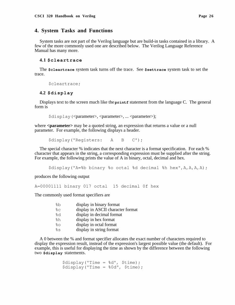
4. System Tasks and Functions
System tasks are not part of the Verilog language but are build-in tasks contained in a library. Afew of the more commonly used one are described below. The Verilog Language ReferenceManual has many more.
4.1 $cleartrace
The $cleartrace system task turns off the trace. See $settrace system task to set thetrace.
$cleartrace;
4.2 $display
Displays text to the screen much like the printf statement from the language C. The generalform is
$display( <parameter>, <parameter>, ... <parameter>);
where <parameter> may be a quoted string, an expression that returns a value or a nullparameter. For example, the following displays a header.
$display("Registers: A B C");
The special character % indicates that the next character is a format specification. For each %character that appears in the string, a corresponding expression must be supplied after the string.For example, the following prints the value of A in binary, octal, decimal and hex.
$display("A=%b binary %o octal %d decimal %h hex",A,A,A,A);
produces the following output
A=00001111 binary 017 octal 15 decimal 0f hex
The commonly used format specifiers are
%b display in binary format%c display in ASCII character format%d display in decimal format%h display in hex format%o display in octal format%s display in string format
A 0 between the % and format specifier allocates the exact number of characters required todisplay the expression result, instead of the expression's largest possible value (the default). Forexample, this is useful for displaying the time as shown by the difference between the followingtwo $display statements.
$display("Time = %d", $time);$display("Time = %0d", $time);
CSCI 320 Handbook on Verilog Page 27
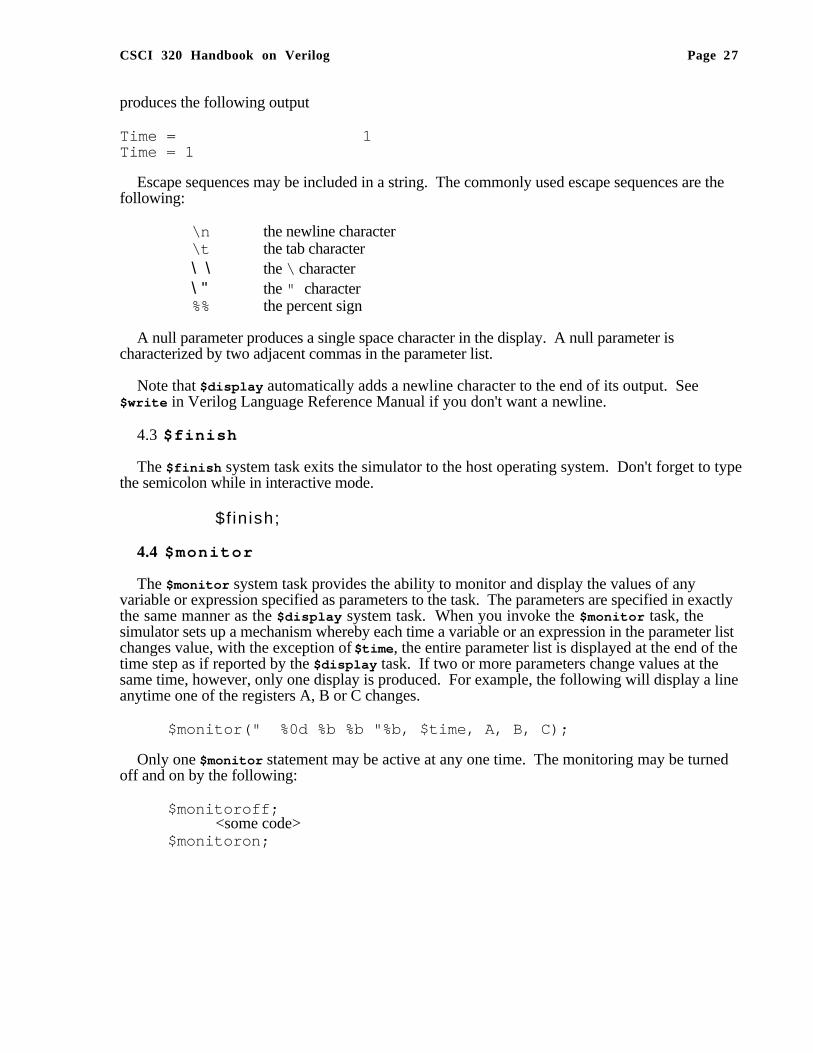
produces the following output
Time = 1Time = 1
Escape sequences may be included in a string. The commonly used escape sequences are thefollowing:
\n the newline character\t the tab character\ \ the \ character\ " the " character%% the percent sign
A null parameter produces a single space character in the display. A null parameter ischaracterized by two adjacent commas in the parameter list.
Note that $display automatically adds a newline character to the end of its output. See$write in Verilog Language Reference Manual if you don't want a newline.
4.3 $finish
The $finish system task exits the simulator to the host operating system. Don't forget to typethe semicolon while in interactive mode.
$f inish;
4.4 $moni tor
The $monitor system task provides the ability to monitor and display the values of anyvariable or expression specified as parameters to the task. The parameters are specified in exactlythe same manner as the $display system task. When you invoke the $monitor task, thesimulator sets up a mechanism whereby each time a variable or an expression in the parameter listchanges value, with the exception of $time , the entire parameter list is displayed at the end of thetime step as if reported by the $display task. If two or more parameters change values at thesame time, however, only one display is produced. For example, the following will display a lineanytime one of the registers A, B or C changes.
$monitor(" %0d %b %b "%b, $time, A, B, C);
Only one $monitor statement may be active at any one time. The monitoring may be turnedoff and on by the following:
$monitoroff; <some code>
$monitoron;

CSCI 320 Handbook on Verilog Page 28
4.5 $scope
The $scope system task lets the user assign a particular level of hierarchy as the interactivescope for identifying objects. $scope is useful during debugging as the user may change thescope to inspect the values of variables in different modules, tasks and functions.
$scope(<name>);
The <name> parameter must be the complete hierarchical name of a module, task, function ornamed block. See $showscopes system task to display the names.
4.6 $settrace
The $settrace system task enables tracing of simulation activity. The trace consists ofvarious information, including the current simulation time, the line number, the file name, moduleand any results from executing the statement.
$settrace;
You can turn off the trace using the $cleartrace system task.
4.7 $showscopes
The $showscopes system task displays a complete lists of all the modules, tasks, functionsand named blocks that are defined at the current scope level.
$showscopes;
4.8 $showvars
The $showvars system task produces status information for register and net (wires) variables,both scalar and vector. When invoked without parameters, $showvars displays the status of allvariables in the current scope. When invoked with a list of variables, it shows only the status ofthe specified variables.
$showvars;$showvars( <list of variables>);
4.9 $stop
The $stop system task puts the simulator into a halt mode, issues an interactive commandprompt and passes control to the user. See Section 3.5 on using VeriWell's interactive mode.
$stop;
4.10 $t ime
The $time system function returns the current simulation time as a 64-bit integer. $timemust be used in an expression.

CSCI 320 Handbook on Verilog Page 29
References
1. Cadence Design Systems, Inc., Verilog-XL Reference Manual.
2. Open Verilog International (OVI), Verilog HDL Language Reference Manual (LRM), 15466Los Gatos Boulevard, Suite 109-071, Los Gatos, CA 95032; Tel: (408)353-8899, Fax: (408) 353-8869, Email: [email protected], $100.
3. Sternheim, E. , R. Singh, Y. Trivedi, R. Madhaven and W. Stapleton, Digital Design andSynthesis with Verilog HDL, published by Automata Publishing Co., Cupertino, CA, 1993,ISBN 0-9627488-2-X, $65.
4. Thomas, Donald E., and Philip R. Moorby, The Verilog Hardware Description Language,second edition, published by Kluwer Academic Publishers, Norwell MA, 1994, ISBN 0-7923-9523-9, $98, includes DOS version of VeriWell simulator and programs on diskette.
5. Bhasker, J., A Verilog HDL Primer, Star Galaxy Press, 1058 Treeline Drive, Allentown, PA18103, 1997, ISBN 0-9656277-4-8, $60.
6. Wellspring Solutions, Inc., VeriWell User’s Guide 1.2, August, 1994, part of free distributionof VeriWell, available online.
7. World Wide Web Pages:FAQ for comp.lang.verilog - http://www.comit.com/~rajesh/verilog/faq/alt_FAQ.htmlcomp.lang.verilog archives - http://www.siliconlogic.com/Verilog/Cadence Design Systems, Inc. - http://www.cadence.com/Wellspring Solutions - ftp://iii.net/pub/pub-site/wellspringVerilog research at Cambridge, England - http://www.cl.cam.uk/users/mjcg/Verilog/
CSCI 320 Handbook on Verilog Page 30
—�—
-, 13
—!—
!, 13!=, 13!==, 14
—$—
$cleartrace, 26$cleartrace, 24, 25$display, 7, 25, 26$finish, 24, 25, 27$monitor , 7, 27$scope, 25, 28$settrace, 25, 28$showscopes, 25, 28$showvars, 25, 28$stop, 7, 24, 25, 28$time, 7, 12, 28
—%—
%, 13, 26
—&—
&, 13, 14&&, 13
—*—
*, 13
—+—
+, 13
—/—
/, 13
—<—
<, 13<<, 14<=, 13, 16
—=—
=, 16==, 13===, 14
—>—
->, 20>, 13>=, 13>>, 14
—?—
?:, 14
—@—
@, 17, 19, 20
—A—
Addition, 13always, 7, 15always, 10AND reduction, 14arithmetic operators, 12assign, 9, 10assign, 16
—B—
begin, 15behavioral level, 4behavioral specification, 8binary, 8Bitwise AND, 13bitwise Boolean operator, 13Bitwise NAND, 13Bitwise negation, 13Bitwise NOR, 13Bitwise NOT XOR, 13Bitwise operators, 13Bitwise OR, 13Bitwise XOR, 13blocking, 16
—C—
Cadence Design Systems, 4Case equality, 14Case inequality, 14case sensitive, 7case statement, 15combinational circuits, 9combinational logic, 10command line, 25Comments, 6concatenate, 11Concatenation, 14concurrent, 7, 8, 20conditional operator, 14continuous assignment, 9, 10, 16control statements, 15Control-c , 24Control-d , 24
—D—
data types, 11Debugging, 25decimal, 8delay control, 17, 19, 20discrete event time simulator, 19

CSCI 320 Handbook on Verilog Page 31
Division, 13
—E—
edge sensitive, 21end, 15Equivalence, 13event, 20event control, 17event expression, 19exit, 24
—F—
finite state automata, 10for statement, 15fork , 21format specification, 26function, 18function subprograms, 17
—G—
gate level, 4Greater than, 13Greater than or equal, 13
—H—
Hardware Description Language, 4HDL , 4hex, 8
—I—
IC , 4if statement, 15init ial , 7, 15in i t ia l , 10inout, 9, 17, 18input, 9, 17input , 18integer, 12Integrated Circuit , 4Interactive mode, 25interconnect, 8invocation, 17
—J—
jo in , 21
—L—
Less than, 13Less than or equal, 13level sensitive, 21Logical AND, 13Logical equality, 13Logical inequality, 13Logical negation, 13Logical operators, 13Logical OR, 13
—M—
memory, 12module, 6Modulus, 13monitoring of variables, 10Multiplication, 13
—N—
NAND reduction, 14negedge, 20non-blocking, 16NOR reduction, 14number, 8
—O—
octal, 8Open Verilog International, 4Operator Precedence, 14operators, 8Options, 24OR reduction, 14output , 17output, 9, 18OVI, 4
—P—
parameter statement, 16pass transistor, 8Port arguments, 17posedge, 20precedence, 14procedural assignment, 16procedural assignments, 10
—R—
range referencing , 12real, 12reduction operators, 14reference, 12reg, 11Register Transfer Level, 4registers, 11Relational operators, 13repeat statement, 16repetition, 12RTL , 4
—S—
scope, 28sequential logic, 10Shift left, 14Shift right, 14sign extension, 12silicon foundry , 5simulated time, 7, 10simulation time, 19s imulat ions, 5Simulator , 24

CSCI 320 Handbook on Verilog Page 32
Simulator Options, 24stop, 24string, 8structural specification, 8Subtraction, 13switch level, 4switches, 8System tasks, 26
—T—
tasks, 17test data, 8, 10thread of control, 20, 21threads of control, 7t ime , 12timing control, 19traffic light, 22tri , 11trigger the event, 20tristate bus, 11
—U—
Unary Minus, 13
—V—
vectors of registers, 12Verilog, 5Verilog HDL, 4Verilog language, 6Verilog-XL, 4VeriWell, 4, 25very large scale integration, 5VHDL, 4, 5VLSI, 5
—W—
wait , 21wait , 19wait queue, 19wait statement, 17wand, 11
while statement, 16wire , 10, 11wire , 16wired and, 11wired or, 11wor , 11
—X—
x, 11, 14XNOR reduction, 14XOR reduction, 14
—Z—
z, 14z, 11
—\—
\\\, 27
—^—
^, 13, 14^~, 13
—{—
{ , }, 14{} , 11
—|—
|, 13, 14||, 13
—~—
~, 13~&, 13, 14~^, 13, 14~|, 13, 14